WO2019146484A1 - 強化繊維マットならびに繊維強化樹脂成形材料およびその製造方法 - Google Patents
強化繊維マットならびに繊維強化樹脂成形材料およびその製造方法 Download PDFInfo
- Publication number
- WO2019146484A1 WO2019146484A1 PCT/JP2019/001219 JP2019001219W WO2019146484A1 WO 2019146484 A1 WO2019146484 A1 WO 2019146484A1 JP 2019001219 W JP2019001219 W JP 2019001219W WO 2019146484 A1 WO2019146484 A1 WO 2019146484A1
- Authority
- WO
- WIPO (PCT)
- Prior art keywords
- reinforcing fiber
- fiber bundle
- bundle
- less
- molding material
- Prior art date
Links
Images


Classifications
-
- D—TEXTILES; PAPER
- D04—BRAIDING; LACE-MAKING; KNITTING; TRIMMINGS; NON-WOVEN FABRICS
- D04H—MAKING TEXTILE FABRICS, e.g. FROM FIBRES OR FILAMENTARY MATERIAL; FABRICS MADE BY SUCH PROCESSES OR APPARATUS, e.g. FELTS, NON-WOVEN FABRICS; COTTON-WOOL; WADDING ; NON-WOVEN FABRICS FROM STAPLE FIBRES, FILAMENTS OR YARNS, BONDED WITH AT LEAST ONE WEB-LIKE MATERIAL DURING THEIR CONSOLIDATION
- D04H1/00—Non-woven fabrics formed wholly or mainly of staple fibres or like relatively short fibres
- D04H1/40—Non-woven fabrics formed wholly or mainly of staple fibres or like relatively short fibres from fleeces or layers composed of fibres without existing or potential cohesive properties
- D04H1/42—Non-woven fabrics formed wholly or mainly of staple fibres or like relatively short fibres from fleeces or layers composed of fibres without existing or potential cohesive properties characterised by the use of certain kinds of fibres insofar as this use has no preponderant influence on the consolidation of the fleece
- D04H1/4209—Inorganic fibres
- D04H1/4242—Carbon fibres
-
- B—PERFORMING OPERATIONS; TRANSPORTING
- B29—WORKING OF PLASTICS; WORKING OF SUBSTANCES IN A PLASTIC STATE IN GENERAL
- B29C—SHAPING OR JOINING OF PLASTICS; SHAPING OF MATERIAL IN A PLASTIC STATE, NOT OTHERWISE PROVIDED FOR; AFTER-TREATMENT OF THE SHAPED PRODUCTS, e.g. REPAIRING
- B29C70/00—Shaping composites, i.e. plastics material comprising reinforcements, fillers or preformed parts, e.g. inserts
- B29C70/04—Shaping composites, i.e. plastics material comprising reinforcements, fillers or preformed parts, e.g. inserts comprising reinforcements only, e.g. self-reinforcing plastics
- B29C70/06—Fibrous reinforcements only
- B29C70/10—Fibrous reinforcements only characterised by the structure of fibrous reinforcements, e.g. hollow fibres
- B29C70/12—Fibrous reinforcements only characterised by the structure of fibrous reinforcements, e.g. hollow fibres using fibres of short length, e.g. in the form of a mat
-
- C—CHEMISTRY; METALLURGY
- C08—ORGANIC MACROMOLECULAR COMPOUNDS; THEIR PREPARATION OR CHEMICAL WORKING-UP; COMPOSITIONS BASED THEREON
- C08J—WORKING-UP; GENERAL PROCESSES OF COMPOUNDING; AFTER-TREATMENT NOT COVERED BY SUBCLASSES C08B, C08C, C08F, C08G or C08H
- C08J5/00—Manufacture of articles or shaped materials containing macromolecular substances
- C08J5/04—Reinforcing macromolecular compounds with loose or coherent fibrous material
- C08J5/06—Reinforcing macromolecular compounds with loose or coherent fibrous material using pretreated fibrous materials
-
- D—TEXTILES; PAPER
- D04—BRAIDING; LACE-MAKING; KNITTING; TRIMMINGS; NON-WOVEN FABRICS
- D04H—MAKING TEXTILE FABRICS, e.g. FROM FIBRES OR FILAMENTARY MATERIAL; FABRICS MADE BY SUCH PROCESSES OR APPARATUS, e.g. FELTS, NON-WOVEN FABRICS; COTTON-WOOL; WADDING ; NON-WOVEN FABRICS FROM STAPLE FIBRES, FILAMENTS OR YARNS, BONDED WITH AT LEAST ONE WEB-LIKE MATERIAL DURING THEIR CONSOLIDATION
- D04H1/00—Non-woven fabrics formed wholly or mainly of staple fibres or like relatively short fibres
- D04H1/40—Non-woven fabrics formed wholly or mainly of staple fibres or like relatively short fibres from fleeces or layers composed of fibres without existing or potential cohesive properties
- D04H1/42—Non-woven fabrics formed wholly or mainly of staple fibres or like relatively short fibres from fleeces or layers composed of fibres without existing or potential cohesive properties characterised by the use of certain kinds of fibres insofar as this use has no preponderant influence on the consolidation of the fleece
- D04H1/4209—Inorganic fibres
- D04H1/4218—Glass fibres
-
- D—TEXTILES; PAPER
- D04—BRAIDING; LACE-MAKING; KNITTING; TRIMMINGS; NON-WOVEN FABRICS
- D04H—MAKING TEXTILE FABRICS, e.g. FROM FIBRES OR FILAMENTARY MATERIAL; FABRICS MADE BY SUCH PROCESSES OR APPARATUS, e.g. FELTS, NON-WOVEN FABRICS; COTTON-WOOL; WADDING ; NON-WOVEN FABRICS FROM STAPLE FIBRES, FILAMENTS OR YARNS, BONDED WITH AT LEAST ONE WEB-LIKE MATERIAL DURING THEIR CONSOLIDATION
- D04H1/00—Non-woven fabrics formed wholly or mainly of staple fibres or like relatively short fibres
- D04H1/40—Non-woven fabrics formed wholly or mainly of staple fibres or like relatively short fibres from fleeces or layers composed of fibres without existing or potential cohesive properties
- D04H1/54—Non-woven fabrics formed wholly or mainly of staple fibres or like relatively short fibres from fleeces or layers composed of fibres without existing or potential cohesive properties by welding together the fibres, e.g. by partially melting or dissolving
- D04H1/558—Non-woven fabrics formed wholly or mainly of staple fibres or like relatively short fibres from fleeces or layers composed of fibres without existing or potential cohesive properties by welding together the fibres, e.g. by partially melting or dissolving in combination with mechanical or physical treatments other than embossing
-
- D—TEXTILES; PAPER
- D04—BRAIDING; LACE-MAKING; KNITTING; TRIMMINGS; NON-WOVEN FABRICS
- D04H—MAKING TEXTILE FABRICS, e.g. FROM FIBRES OR FILAMENTARY MATERIAL; FABRICS MADE BY SUCH PROCESSES OR APPARATUS, e.g. FELTS, NON-WOVEN FABRICS; COTTON-WOOL; WADDING ; NON-WOVEN FABRICS FROM STAPLE FIBRES, FILAMENTS OR YARNS, BONDED WITH AT LEAST ONE WEB-LIKE MATERIAL DURING THEIR CONSOLIDATION
- D04H1/00—Non-woven fabrics formed wholly or mainly of staple fibres or like relatively short fibres
- D04H1/40—Non-woven fabrics formed wholly or mainly of staple fibres or like relatively short fibres from fleeces or layers composed of fibres without existing or potential cohesive properties
- D04H1/58—Non-woven fabrics formed wholly or mainly of staple fibres or like relatively short fibres from fleeces or layers composed of fibres without existing or potential cohesive properties by applying, incorporating or activating chemical or thermoplastic bonding agents, e.g. adhesives
- D04H1/60—Non-woven fabrics formed wholly or mainly of staple fibres or like relatively short fibres from fleeces or layers composed of fibres without existing or potential cohesive properties by applying, incorporating or activating chemical or thermoplastic bonding agents, e.g. adhesives the bonding agent being applied in dry state, e.g. thermo-activatable agents in solid or molten state, and heat being applied subsequently
-
- B—PERFORMING OPERATIONS; TRANSPORTING
- B29—WORKING OF PLASTICS; WORKING OF SUBSTANCES IN A PLASTIC STATE IN GENERAL
- B29B—PREPARATION OR PRETREATMENT OF THE MATERIAL TO BE SHAPED; MAKING GRANULES OR PREFORMS; RECOVERY OF PLASTICS OR OTHER CONSTITUENTS OF WASTE MATERIAL CONTAINING PLASTICS
- B29B15/00—Pretreatment of the material to be shaped, not covered by groups B29B7/00 - B29B13/00
- B29B15/08—Pretreatment of the material to be shaped, not covered by groups B29B7/00 - B29B13/00 of reinforcements or fillers
- B29B15/10—Coating or impregnating independently of the moulding or shaping step
- B29B15/12—Coating or impregnating independently of the moulding or shaping step of reinforcements of indefinite length
-
- C—CHEMISTRY; METALLURGY
- C08—ORGANIC MACROMOLECULAR COMPOUNDS; THEIR PREPARATION OR CHEMICAL WORKING-UP; COMPOSITIONS BASED THEREON
- C08J—WORKING-UP; GENERAL PROCESSES OF COMPOUNDING; AFTER-TREATMENT NOT COVERED BY SUBCLASSES C08B, C08C, C08F, C08G or C08H
- C08J2323/00—Characterised by the use of homopolymers or copolymers of unsaturated aliphatic hydrocarbons having only one carbon-to-carbon double bond; Derivatives of such polymers
- C08J2323/02—Characterised by the use of homopolymers or copolymers of unsaturated aliphatic hydrocarbons having only one carbon-to-carbon double bond; Derivatives of such polymers not modified by chemical after treatment
- C08J2323/10—Homopolymers or copolymers of propene
- C08J2323/12—Polypropene
-
- C—CHEMISTRY; METALLURGY
- C08—ORGANIC MACROMOLECULAR COMPOUNDS; THEIR PREPARATION OR CHEMICAL WORKING-UP; COMPOSITIONS BASED THEREON
- C08J—WORKING-UP; GENERAL PROCESSES OF COMPOUNDING; AFTER-TREATMENT NOT COVERED BY SUBCLASSES C08B, C08C, C08F, C08G or C08H
- C08J2363/00—Characterised by the use of epoxy resins; Derivatives of epoxy resins
-
- C—CHEMISTRY; METALLURGY
- C08—ORGANIC MACROMOLECULAR COMPOUNDS; THEIR PREPARATION OR CHEMICAL WORKING-UP; COMPOSITIONS BASED THEREON
- C08J—WORKING-UP; GENERAL PROCESSES OF COMPOUNDING; AFTER-TREATMENT NOT COVERED BY SUBCLASSES C08B, C08C, C08F, C08G or C08H
- C08J2377/00—Characterised by the use of polyamides obtained by reactions forming a carboxylic amide link in the main chain; Derivatives of such polymers
-
- C—CHEMISTRY; METALLURGY
- C08—ORGANIC MACROMOLECULAR COMPOUNDS; THEIR PREPARATION OR CHEMICAL WORKING-UP; COMPOSITIONS BASED THEREON
- C08J—WORKING-UP; GENERAL PROCESSES OF COMPOUNDING; AFTER-TREATMENT NOT COVERED BY SUBCLASSES C08B, C08C, C08F, C08G or C08H
- C08J2463/00—Characterised by the use of epoxy resins; Derivatives of epoxy resins
-
- C—CHEMISTRY; METALLURGY
- C08—ORGANIC MACROMOLECULAR COMPOUNDS; THEIR PREPARATION OR CHEMICAL WORKING-UP; COMPOSITIONS BASED THEREON
- C08J—WORKING-UP; GENERAL PROCESSES OF COMPOUNDING; AFTER-TREATMENT NOT COVERED BY SUBCLASSES C08B, C08C, C08F, C08G or C08H
- C08J2477/00—Characterised by the use of polyamides obtained by reactions forming a carboxylic amide link in the main chain; Derivatives of such polymers
Definitions
- the present invention relates to a reinforced fiber mat and a fiber-reinforced resin molding material which are excellent in mechanical properties, complex shape moldability and productivity.
- CFRPs Carbon fiber reinforced composite materials
- CFRP As an application example of CFRP to a car, a prepreg, a resin transfer molding (RTM), and a member by filament winding (FW) using thermosetting resin which has been proven in aircraft and sports materials are put on the market.
- CFRP using a thermoplastic resin can be molded at high speed and has excellent recyclability, and therefore, it is attracting attention as a material for mass production vehicles.
- press forming has high productivity and can cope with forming of complicated shapes and large areas, so that it is expected to be an alternative to metal forming.
- a sheet-like material using discontinuous reinforcing fibers is mainly used as an intermediate base material for press molding.
- SMC sheet molding compound
- GTT glass mat thermoplastic
- Any intermediate base material is used for so-called flow stamping, in which the material is fluidly filled in the mold cavity, and relatively long reinforcing fibers are chopped strands and / or swirls into the thermoplastic resin. It takes a dispersed form. Since the fiber bundle is composed of a large number of single yarns, the flowability at the time of molding is excellent, but the mechanical properties of the molded article tend to be inferior.
- continuous production of an intermediate base material is required to continuously supply reinforcing fiber bundles in order to reduce production costs and improve productivity.
- a molding material having a multilayer structure composed of sheets having different fiber length and concentration parameters has been proposed as a combination of mechanical properties and fluidity.
- fiber bundles (a patent document 4) including a separation processing section and an undivision processing section, which are constituent materials of a molding material having excellent mechanical properties and fluidity.
- pattern 5 which improved mechanical characteristics by adjusting thickness, width, etc. of a fiber bundle.
- the present invention is a fiber-reinforced resin molding material excellent in productivity, which can impart high mechanical properties to a molded body using such a fiber-reinforced resin molding material, and further, fluidity in molding It is an object of the present invention to provide a reinforced fiber mat and a fiber-reinforced resin molding material excellent in the above.
- the present inventors came to invent the reinforced fiber mat and the fiber reinforced resin molding material which can solve the said subject. That is, the present invention is configured as follows. [1] The reinforcing fiber bundle having an average fiber length of 5 mm or more and 100 mm or less, and the weight ratio of the bundle of fibers in the bundle of 86 or more of the reinforcing fiber bundle is more than 99% by weight and 100% by weight or less Characterized by a reinforced fiber mat.
- the reinforcing fiber mat characterized in that the number of single yarns per unit width of the reinforcing fiber bundle is 500 / mm to 1,600 / mm, and the drape value is 120 mm to 240 mm.
- bundle hardness of the reinforcing fiber bundle is 39 g or more and 200 g or less.
- thermoplastic resin and a reinforcing fiber bundle Containing a thermoplastic resin and a reinforcing fiber bundle, the porosity is 5% by volume or more and 30% by volume or less, and the reinforcing fiber bundle has a number of single yarns per unit width of 500 / mm or more and 1600 / mm or less And a fiber-reinforced resin molding material characterized in that the reinforcing fiber bundle has a drape value of 120 mm or more and 240 mm or less.
- a method for producing a fiber-reinforced thermoplastic resin molding material comprising the following steps [A] to [D].
- B spreading or laminating a thermoplastic resin on the mat substrate.
- C A step of melting the thermoplastic resin.
- D A step of cooling and solidifying the melted thermoplastic resin between the plate surfaces that are 5% or more thicker than the substrate thickness at the time of complete resin impregnation.
- the reinforced fiber mat and the fiber reinforced resin molding material which are excellent in a dynamic characteristic, the fluidity
- carbon fiber is preferable.
- the carbon fiber is not particularly limited.
- carbon fibers such as polyacrylonitrile (PAN) -based, pitch-based and rayon-based carbon fibers can be preferably used from the viewpoint of improvement of mechanical properties and weight reduction effect of fiber reinforced resin. You may use together 1 type or 2 types or more. Among them, PAN-based carbon fibers are more preferable from the viewpoint of the balance between the strength and elastic modulus of the obtained fiber reinforced resin.
- PAN polyacrylonitrile
- the single fiber diameter of the reinforcing fiber is preferably 0.5 ⁇ m or more, more preferably 2 ⁇ m or more, and still more preferably 4 ⁇ m or more. Moreover, 20 micrometers or less are preferable, as for the single fiber diameter of a reinforced fiber, 15 micrometers or less are more preferable, and 10 micrometers or less are more preferable.
- the strand strength of the reinforcing fiber is preferably 3.0 GPa or more, more preferably 4.0 GPa or more, and still more preferably 4.5 GPa or more. 200 GPa or more is preferable, as for the strand elasticity modulus of a reinforced fiber, 220 GPa or more is more preferable, and 240 GPa or more is more preferable. If the strand strength or elastic modulus of the reinforcing fiber is in this range, respectively, the mechanical properties of the molded article made of the reinforcing fiber mat of the present invention and the resin can be enhanced.
- the upper limit of the average number of fibers in the discontinuous reinforcing fiber bundle constituting the reinforcing fiber mat of the present invention is preferably 4,000 or less, more preferably 3,000 or less, still more preferably 2,000 or less. Within this range, the mechanical properties of the reinforcing fiber mat can be enhanced.
- the lower limit of the number of fibers in the bundle is preferably 50 or more, more preferably 100 or more, and still more preferably 200 or more. Within this range, the flowability of the molding material comprising the reinforcing fiber mat of the present invention and the resin can be enhanced. The method of deriving the average number of fibers will be described later.
- the sizing agent attached to the reinforcing fibers constituting the reinforcing fiber mat of the present invention is not particularly limited, but compounds having functional groups such as epoxy group, urethane group, amino group and carboxyl group can be used, and one or more of these may be used. Two or more may be used in combination.
- the water-soluble polyamide is polycondensed from a diamine having a tertiary amino group and / or an oxyethylene group in the main chain and a carboxylic acid
- the polyamide resin is obtained by the following method: N, N'-bis (.gamma.-aminopropyl) piperazine having a piperazine ring, N-(.
- Alkyl diamines containing oxyethylene groups in the main chain of monomers, oxyethylene alkylamines and the like are useful.
- dicarboxylic acids include adipic acid and sebacic acid.
- the water soluble polyamide may be a copolymer.
- the copolymerization component include lactams such as ⁇ -pyrrolidone, ⁇ -piperidone, ⁇ -caprolactam, ⁇ -methyl- ⁇ -caprolactam, ⁇ -methyl- ⁇ -caprolactam, ⁇ -laurolactam, etc.
- lactams such as ⁇ -pyrrolidone, ⁇ -piperidone, ⁇ -caprolactam, ⁇ -methyl- ⁇ -caprolactam, ⁇ -methyl- ⁇ -caprolactam, ⁇ -laurolactam, etc.
- the copolymerization ratio is determined within a range that does not interfere with the physical property of water solubility.
- the polymer does not completely dissolve in water unless the proportion of copolymerization components having a lactam ring is within 30% by weight.
- the solubility is increased when the solution is made acidic using an organic and inorganic acid, and it becomes water soluble and can be used.
- organic acid include acetic acid, chloracetic acid, propionic acid, maleic acid, oxalic acid and fluoroacetic acid
- inorganic acid include common mineral acids such as hydrochloric acid, sulfuric acid and phosphoric acid.
- This water-soluble polyamide may be used as a primary sizing agent for reinforcing fibers to which no sizing agent has been applied, or may be used as a secondary sizing agent for reinforcing fibers to which a sizing agent has been applied beforehand.
- the amount of adhesion of the sizing agent is preferably 5% by weight or less, more preferably 4% by weight or less, and still more preferably 3% by weight or less, based on 100% by weight of the reinforcing fiber bundle to which the sizing agent is attached. If the adhesion amount of the sizing agent exceeds 5% by weight, the flexibility of the fiber bundle is lacking and the fiber bundle becomes too hard, and the bobbin may not be smoothly wound and unwound. In addition, single yarn breakage may occur at the time of cutting, which may result in the failure to obtain an ideal chopped fiber form.
- 0.1 weight% or more is preferable, as for the adhesion amount of a sizing agent, 0.3 weight% or more is more preferable, and 0.5 weight% or more is more preferable. If the adhesion amount of the sizing agent is less than 0.1% by weight, the adhesion between the matrix and the reinforcing fibers tends to be reduced, and the mechanical properties of the molded article may be lowered, when trying to produce the molded article . In addition, since the filament is broken and fluff is generated, the unwinding property from the bobbin may be reduced, and winding on the nip roller and the cutter blade may occur. The method for deriving the adhesion amount of the sizing agent will be described later.
- the adhesion amount of the sizing agent in the above range, when cutting the fiber bundle with, for example, a cutter, the effect of improving the unwinding property from the bobbin and reducing the winding on the nip roller and the cutter blade can be obtained. It is possible to improve the sex. Furthermore, it is possible to suppress breakage of the cut fiber bundle and dispersion of single yarn, and the retention of the predetermined bundle form is improved.
- the distribution of the number of single yarns forming the discontinuous reinforcing fiber bundle is narrowed by the reinforcing fiber mat consisting of the discontinuous reinforcing fiber bundle to which the cut fiber bundle is dispersed, and the uniform and optimal form discontinuous reinforcing fiber bundle It is possible to get As a result, the fiber bundle is plane-oriented, and mechanical characteristics can be further improved. Furthermore, it is possible to reduce variations in mechanical properties of a molded article.
- These sizing agents are preferably uniformly attached to the surface of the reinforcing fiber.
- these sizing agents may be used in concentrations of 0.1% by weight or more, preferably 1% by weight to 20% by weight of water or alcohol, acidic aqueous solution.
- a method of dissolving and immersing the fiber bundle in the sizing agent treatment liquid through the roller in the polymer solution, a method of contacting the fiber bundle with the roller to which the sizing agent treatment liquid is attached, and making the sizing agent treatment liquid into a mist There are methods such as spraying on a bundle.
- the sizing agent treatment liquid concentration, temperature, yarn tension and the like so that the adhesion amount of the sizing agent active component to the fiber bundle is uniformly adhered within an appropriate range.
- any method such as heat treatment, air drying, or centrifugation may be used, and among them, heat treatment is preferable from the viewpoint of cost.
- heat treatment for example, hot air, a hot plate, a roller, an infrared heater or the like can be used.
- the heat treatment conditions are also important, and are related to the handling and the adhesion to the matrix material. That is, the heat treatment temperature and time after applying the sizing agent to the fiber bundle should be adjusted according to the components of the sizing agent and the adhesion amount.
- the water-soluble polyamide In the case of the water-soluble polyamide, from the viewpoint of preventing heat deterioration, it is dried at room temperature to 180 ° C. to remove moisture, and then heat-treated. 130 degreeC or more is preferable and, as for the minimum of heat processing temperature, 200 degreeC or more is more preferable. 350 degrees C or less is preferable and, as for the upper limit of heat processing temperature, 280 degrees C or less is more preferable.
- the heat treatment temperature is a temperature at which the water-soluble polyamide self-crosslinks or loses water solubility by oxygen in air.
- the water-soluble polymer becomes insoluble and loses hygroscopicity, so that the filament-concentrated strand is not sticky and the post-processing workability is improved, and the adhesion to the matrix material is improved and the handling is easy. It can provide a fiber bundle. Moreover, it is also possible to add a crosslinking accelerator to the solvent to lower the heat treatment temperature or shorten the time. Moreover, the hardness of a fiber bundle can also be raised by performing an aging process in 23 +/- 5 degreeC atmosphere.
- Sizing agents using this water-soluble polyamide resin are excellent in affinity with various matrix materials and can significantly improve the composite physical properties, but in particular, polyamide resins, polyimide resins, polyamideimide resins, and polyetheramideimide resins It has the effect of improving adhesion in resin.
- the reinforcing fiber to which the primary sizing agent is applied may be applied in the same manner as the above method, or may be applied in the process of producing a reinforcing fiber bundle.
- the sizing agent is contained in a solvent (including a dispersion medium in the case of dispersion).
- a sizing agent is applied to a fiber bundle by preparing a dissolved (including dispersed) sizing agent treatment liquid and applying the sizing agent treatment liquid to a fiber bundle, followed by drying, evaporation and removal of a solvent. Generally done.
- partial separation processing or fiber bundle widening processing may be performed between the coating step and the drying step.
- 200 degreeC or more is preferable, as for the thermal decomposition start temperature of the sizing agent in this invention, 250 degreeC or more is more preferable, and 300 degreeC or more is more preferable.
- the method of deriving the thermal decomposition start temperature will be described later.
- FIG. 3 shows an example of the timing of the sizing agent application process in the process of manufacturing the reinforcing fiber bundle in the method of manufacturing the reinforcing fiber bundle constituting the reinforcing fiber mat according to the present invention.
- the sizing agent applying step 400 is performed prior to the partially divided fiber processing step 300.
- a pattern A and a pattern B to be performed after the partial separation processing step 300 are shown. Both timings of pattern A and pattern B are possible.
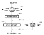
- FIG. 4 shows a timing example of the sizing agent application process 400 during the process of manufacturing the reinforcing fiber bundle in the method of manufacturing a reinforcing fiber bundle including the fiber bundle widening process 301 according to the present invention.
- the sizing agent applying step 400 A pattern C performed before the step 301, a pattern D performed between the fiber bundle widening step 301 and the partial separation treatment step 300, and a pattern E performed after the partial separation treatment step 300 are shown. It is done.
- the timing of the pattern D is most preferable from the viewpoint of achieving the optimum partial separation processing.
- FIG. 5 shows a timing example of a sizing agent application process including a sizing agent application process and a drying process in the manufacturing process of the reinforcing fiber bundle in the method of manufacturing the reinforcing fiber bundle constituting the reinforcing fiber mat according to the present invention
- the sizing agent application process 400 includes a sizing agent application process 401 and a drying process 402.
- the sizing agent application process 400 including the sizing agent application process 401 and the drying process 402 is described.
- a pattern F performed before the partially divided fiber step 300 and a pattern G performed after the partially divided fiber step 300 It is shown. Either timing of pattern F or pattern G is possible.
- the pattern F is substantially the same as the pattern A in FIG. 3 and the pattern G is substantially the same as the pattern B in FIG.
- FIG. 6 shows another timing example of the sizing agent application process including the sizing agent application process and the drying process in the manufacturing process of the reinforcing fiber bundle in the method of manufacturing the reinforcing fiber bundle constituting the reinforcing fiber mat according to the present invention. It shows.
- the sizing agent application process 401 and the drying process 402 in the sizing agent application process 400 are separated and performed at different timings.
- the sizing agent application process 401 is performed before the partial separation treatment process 300, and the drying process 402 is performed after the partial separation treatment process 300.
- FIG. 7 shows a timing example of a sizing agent application process including a sizing agent application process and a drying process in the method for producing a reinforced fiber bundle including the fiber bundle widening process according to the present invention, and the fiber bundle 100 is fiber bundle widening.
- the sizing agent application step 401 of the sizing agent application step is performed before the fiber bundle widening step 301.
- the drying step 402 a pattern I performed between the fiber bundle widening step 301 and the partial separation treatment step 300 and a pattern J performed after the partial separation treatment step 300 are shown.
- FIG. 8 shows another timing example of the sizing agent application process including the sizing agent application process and the drying process in the method for producing a reinforced fiber bundle including the fiber bundle widening process according to the present invention
- the fiber bundle 100 is a fiber
- the sizing agent application step 401 of the sizing agent application step includes the fiber bundle widening step 301 and the partial portion A pattern K is shown which is performed between the fiber treatment process 300 and the drying process 402 is performed after the partial separation process 300.
- the weight ratio of the bundle having 86 or more fibers in the bundle is preferably more than 99% by weight and not more than 100% by weight. If the weight ratio of the bundle with 86 or more fibers is 99% by weight or less, there is a concern that the flowability of the molding material may be inferior.
- the drape value of the reinforced fiber bundle which comprises the reinforced fiber mat of this invention 145 mm or more is more preferable, and 170 mm or more is more preferable. If the drape value is smaller than 120 mm, the filament may be broken and fluff may occur, resulting in a decrease in the unwinding property from the bobbin and winding on the nip roller and the cutter blade. It is preferable that it is 240 mm or less, 230 mm or less is more preferable, and 220 mm or less is more preferable. When the drape value exceeds 240 mm, the flexibility of the fiber bundle is lacking and the fiber bundle becomes too hard, and the bobbin may not be smoothly wound and unwound. In addition, single yarn breakage may occur at the time of cutting, which may result in failure to obtain an ideal chopped fiber bundle form. The method of deriving the drape value of the reinforcing fiber bundle constituting the reinforcing fiber mat will be described later.
- the bundle hardness of the reinforcing fiber bundle constituting the reinforcing fiber mat of the present invention is preferably 39 g or more, more preferably 70 g or more, and still more preferably 120 g or more. If the hardness is less than 39 g, the filament may be broken and fuzz may be generated to reduce the unwinding property from the bobbin and to cause winding on the nip roller and the cutter blade.
- the bundle hardness of the reinforcing fiber bundle constituting the reinforcing fiber mat is preferably 200 g or less, more preferably 190 g or less, and still more preferably 180 g or less.
- the number of single yarns per unit width of the discontinuous reinforcing fiber bundle constituting the reinforcing fiber mat of the present invention is preferably 500 yarns / mm or more, more preferably 600 yarns / mm or more, and still more preferably 700 yarns / mm or more. If it is less than 500 / mm, there is a concern that the flowability of the molding material may be poor.
- the number is preferably 1,600 or less, more preferably 1,400 or less, and still more preferably 1,200 or less. If it exceeds 1,600 / mm, there is a concern that the mechanical properties of the molded article may be inferior.
- the method of deriving the number of single yarns per unit width of the discontinuous reinforcing fiber bundle constituting the reinforcing fiber mat will be described later.
- the weight average fiber length of the discontinuous reinforcing fiber bundle constituting the reinforcing fiber mat of the present invention is preferably 5 mm or more, preferably 7 mm or more, and more preferably 10 mm or more.
- the weight average fiber length of the discontinuous reinforcing fiber bundle is preferably 100 mm or less, preferably 50 mm or less, and more preferably 25 mm or less. If the weight average fiber length of the reinforcing fiber bundle is less than 5 mm, the mechanical properties of the molded article are degraded. On the other hand, when the weight average fiber length of the reinforcing fiber bundle exceeds 100 mm, the formability is reduced.
- the weight average fiber length is an average value of the fiber length Lf shown in FIG.
- the angle (cutting angle ⁇ ) of the cut surface with respect to the fiber direction of the reinforcing fiber bundle 102 is preferably 3 ° or more, more preferably 4 ° or more, and still more preferably 5 ° or more. Within this range, the fiber bundle can be cut stably. Moreover, 30 degrees or less are preferable, 25 degrees or less are more preferable, and 15 degrees or less are more preferable. Within this range, good fluidity in molding and high mechanical properties of the molded article can be realized. Note that ⁇ is represented by an absolute value.
- 0.01 mm or more is preferable, as for the thickness of the discontinuous reinforcing fiber bundle which comprises the reinforcing fiber mat of this invention, 0.03 mm or more is more preferable, and 0.05 mm or more is more preferable. If it is less than 0.01 mm, there is a concern that the flowability of the molding material may be poor.
- the thickness of the discontinuous reinforcing fiber bundle constituting the reinforcing fiber mat is preferably 0.2 mm or less, more preferably 0.18 mm or less, and still more preferably 0.16 mm or less. If it exceeds 0.2 mm, there is a concern that the mechanical properties of the molded article may be inferior.
- the number average bundle width of the discontinuous reinforcing fiber bundles constituting the reinforcing fiber mat of the present invention is preferably 0.03 mm or more, more preferably 0.05 mm or more, and still more preferably 0.07 mm or more. If it is less than 0.03 mm, there is a concern that the flowability of the molding material may be poor.
- the average bundle width of the discontinuous reinforcing fiber bundle constituting the reinforcing fiber mat is preferably 3 mm or less, more preferably 2 mm or less, and still more preferably 1 mm or less. If it exceeds 3 mm, there is a concern that the mechanical properties of the molded article may be inferior.
- the reinforcing fiber bundle After immersing the discontinuous reinforcing fiber bundle constituting the reinforcing fiber mat of the present invention in water before immersion in water, the reinforcing fiber bundle is immersed in water at 25 ° C. for 5 minutes, then taken out and drained for 1 minute.
- the width of the reinforcing fiber bundle is W2
- the width change ratio W2 / W1 of the reinforcing fiber bundle is preferably 0.5 or more, more preferably 0.6 or more, and still more preferably 0.7 or more. If the width change ratio W2 / W1 of the discontinuous reinforcing fiber bundle to which the sizing agent is applied is smaller than 0.5, the water-soluble physical properties of the sizing agent attached to the discontinuous reinforcing fiber bundle remain.
- the separated fiber bundle may reaggregate, and when it is reaggregated, it becomes difficult to maintain the form of the fiber bundle adjusted to the optimum number of single yarns.
- the split fiber bundle is cut / dispersed for producing a molding material used for forming a composite material, and is used as an intermediate base of the discontinuous fiber bundle. In such a case, it becomes difficult to make the intermediate base material of the optimum form, and it becomes difficult to achieve well-balanced flowability in molding and mechanical properties of the molded article.
- the width change rate W2 / W1 is preferably 1.1 or less.
- width change ratio W2 / W1 exceeds 1.1, the flexibility of the fiber bundle is lacking and it becomes too hard, and there is a possibility that the winding and unwinding of the bobbin may not be smooth. In addition, single yarn breakage may occur at the time of cutting, which may result in failure to obtain an ideal chopped fiber bundle form.
- the method of deriving the width change ratio W2 / W1 of the reinforcing fiber bundle will be described later.
- the matrix thermoplastic resin [M] to be impregnated into the reinforcing fiber mat of the discontinuous reinforcing fiber bundle is not particularly limited.
- PBT butylene terephthalate
- PET polyethylene terephthalate
- PPS polyphenylene sulfide
- PEEK polyetheretherketone
- liquid crystal polymer polyvinyl chloride
- fluorine resin such as polytetrafluoroethylene, silicone, etc.
- thermoplastic polyamide resin used in the present invention can be obtained, for example, by polycondensation of nylon 6, nylon 11, nylon 12 or diamine and diamine with dicarboxylic acid obtained by ring-opening polymerization of cyclic lactam or polycondensation of ⁇ -aminocarboxylic acid.
- Copolymerized nylon such as 12 can be suitably used.
- nylon 6, 66, 610 is preferred in view of mechanical properties and cost.
- copper halide or derivatives thereof used in the present invention copper iodide, copper bromide, copper chloride, a complex salt of mercaptobenzimidazole and copper iodide, and the like can be mentioned. Among them, copper iodide and a complex salt of mercaptobenzimidazole and copper iodide can be suitably used.
- the addition amount of the copper halide or its derivative is preferably in the range of 0.001 to 5 parts by weight with respect to 100 parts by weight of the thermoplastic polyamide resin.
- the addition amount is less than 0.001 part, it is not possible to suppress resin decomposition, smoke and odor during preheating, and if it is 5 parts by weight or more, improvement of the improvement effect can not be observed. Furthermore, 0.002 to 1 part by weight is preferable because of the balance between the heat stabilization effect and the cost.
- the method for impregnating the reinforcing fiber mat of the discontinuous reinforcing fiber bundle with the matrix resin is not particularly limited, and the method for impregnating the thermoplastic resin may be, for example, a reinforcing fiber mat containing thermoplastic resin fibers.
- the thermoplastic resin fibers contained in the reinforcing fiber mat may be used as they are as a matrix resin, or any step of manufacturing the reinforcing fiber mat using the reinforcing fiber mat containing no thermoplastic resin fiber as a raw material
- the matrix resin may be impregnated with
- the matrix resin can be impregnated at any stage of producing the reinforcing fiber mat.
- the resin constituting the thermoplastic resin fiber and the matrix resin may be the same resin or different resins.
- the resin constituting the thermoplastic resin fiber is different from the matrix resin, it is preferable that the two have compatibility or high affinity.
- the fiber-reinforced resin molding material of the present invention mainly comprises a reinforcing fiber bundle and a thermoplastic resin, and has a void of 5% by volume or more. 7 volume% or more is preferable and 10 volume% or more of a porosity is more preferable. If the porosity is less than 5% by volume, the base material of the reinforcing fiber bundle may flow and high-speed production may not be possible. On the other hand, although the upper limit of the porosity is 30 volume%, 25 volume% or less is preferable and 20 volume% or less is more preferable. When it exceeds 30% by volume, it means that the impregnation property of the thermoplastic resin is deteriorated and the mechanical properties may be deteriorated. The method of deriving the porosity will be described later.
- the mechanical properties, flowability, and productivity can be significantly improved by simultaneously setting the void ratio of the fiber-reinforced resin molding material, the number of single yarns per unit width of the reinforcing fiber bundle, and the drape value described above. it can.
- thermoplastic resin which is a matrix resin
- the press is not particularly limited as long as it can realize the temperature and pressure necessary for the impregnation of the matrix resin, and a normal press having a flat platen which moves up and down, and a mechanism on which a pair of endless steel belts travel So-called double belt presses can be used.
- the matrix resin is formed into a sheet form such as a film, nonwoven fabric or woven fabric and then laminated with a discontinuous fiber mat, and the matrix resin can be melted and impregnated using the above-mentioned press or the like in that state.
- the particulate matrix resin may be sprayed onto the reinforcing fiber mat to form a laminate, or the discontinuous reinforcing fiber bundle may be sprayed at the same time as the dispersion and dispersed into the reinforcing fiber mat.
- the fiber-reinforced thermoplastic resin molding material of the present invention configured as described above is produced, for example, by the following steps [A] to [D].
- [A] A step of producing a mat substrate of a reinforcing fiber bundle having a number of single yarns per unit width of 500 / mm to 1600 / mm and a drape value of 120 mm to 240 mm.
- [B] spreading or laminating a thermoplastic resin on the mat substrate.
- [C] A step of melting a thermoplastic resin.
- [D] A step of cooling and solidifying the melted thermoplastic resin between the plate surfaces that are 5% or more thicker than the substrate thickness at the time of complete resin impregnation.
- the reinforcing fiber bundle having the physical properties as described above is cut, for example, to a desired length, and dispersed in a sheet form, thereby forming a mat substrate comprising the reinforcing fiber bundle of discontinuous fibers Do.
- step [B] particles of a thermoplastic resin to be a matrix resin are dispersed on the mat substrate obtained in the step [A], or a sheet-like thermoplastic resin such as a film, nonwoven fabric or fabric is mat It laminates on a substrate.
- a sheet-like thermoplastic resin such as a film, nonwoven fabric or fabric is mat It laminates on a substrate.
- particles of the thermoplastic resin may be sprayed at the same time, and the thermoplastic resin may be mixed inside the mat substrate.
- the said process [C] and [D] can be performed using a press, and the mat
- the press is not particularly limited as long as it can realize the temperature and pressure necessary for the impregnation of the matrix resin, and a normal press having a flat platen which moves up and down, and a mechanism on which a pair of endless steel belts travel So-called double belt presses can be used.
- the gap between the board surfaces should be at least 5% greater than the thickness of the substrate upon complete resin impregnation. The substrate thickness at the time of complete resin impregnation will be described later.
- the fiber-reinforced thermoplastic resin molding material obtained by the above-described series of steps uses a reinforcing fiber bundle having specific physical properties, and since the porosity in the molding material is in the above-mentioned range, the productivity is improved. In addition to being able to be enhanced, as a molded body using such a molding material, it is possible to exhibit high mechanical properties and also to be excellent in fluidity at the time of molding.
- the porosity of the fiber-reinforced resin molding material is an average value of 10 samples derived from the following formula (4) according to JIS K-7075 (1991).
- the fiber mass content Wf (%) is measured by a combustion method under nitrogen atmosphere conditions at 500 ° C. for 15 minutes, and can be derived by the following equation (1).
- the specific gravity cc of the fiber-reinforced resin molding material is measured according to method A (underwater substitution method) of JIS K-7112 (1999).
- the substrate thickness at the time of complete resin impregnation of fiber reinforced resin molding material is mass P (per unit area of fiber reinforced resin molding material) / M 2 ), fiber volume content Vf of fiber reinforced resin molding material at the time of complete resin impregnation, resin volume content Vr of fiber reinforced resin molding material at the time of complete resin impregnation, specific gravity ⁇ f of reinforcing fiber, specific gravity of thermoplastic resin It is derived from the following equation (5) including r r and is an average value of 10 samples.
- the weight a (mg / m) per 1 m of filaments is derived from the weight of the reinforcing fiber bundle per 1 m and the number of filaments constituting the reinforcing fiber bundle.
- the fiber length c (mm) and the weight b (mg) of the reinforcing fiber bundle cut to a length of about 10 mm are measured, and the number of fibers constituting the bundle is derived by the following formula (6).
- the thermal decomposition start temperature of the sizing agent is measured as follows. First, about 5 mg of a reinforcing fiber bundle coated with a sizing agent is collected, dried at 110 ° C. for 2 hours, and cooled in a desiccator at room temperature for 1 hour. Then, weigh and measure TGA in an air atmosphere. The air flow rate is 50 ml / min, the heating rate is 10 ° C./min, and the weight loss from room temperature to 650 ° C. is measured.
- the weight ratio (%) of the size yarn to the initial weight on the vertical axis and the TGA curve on the horizontal axis as temperature (° C), the temperature at which the rate of weight loss (% / ° C) is maximum and the closest to the lower temperature side
- the temperature at which the rate of weight loss is minimized is searched for, and the intersection of each tangent is defined as the thermal decomposition initiation temperature.
- the definition of the thermal decomposition initiation temperature is applied to the state before the matrix resin impregnation after chemical modification of the sizing agent. If the thermal decomposition onset temperature of the reinforcing fiber bundle to which the sizing agent has been applied can not be measured, the sizing agent can be used instead of the reinforcing fiber bundle.
- the reinforcing fiber bundle cut to 30 cm is fixed to the end of the rectangular base, and at this time, the reinforcing fiber bundle is fixed so as to project 25 cm from the end of the base That is, the portion 5 cm from the end of the reinforcing fiber is placed at the end of the table, and after standing for 5 minutes in this state, the tip of the reinforcing fiber bundle not fixed to the table and the side of the table
- the measured value of the shortest distance was taken as the drape value.
- the hardness of the reinforcing fiber bundle is measured using HANDLE-O-Meter ("CAN-1 MCB" manufactured by Daiei Kagaku Seiki, Ltd.) according to JIS L-1096 E method (handle ohm method). did.
- the reinforcing fiber bundle was opened and adjusted so that the length of the test piece used for measuring the bundle hardness was 10 cm and the width was 1 mm with 1600 filaments.
- the slit width was set to 20 mm.
- One reinforcing fiber bundle as a test piece was placed on the test stand provided with the slit grooves, and the resistance (g) generated when the test piece was pushed into the groove to a predetermined depth (8 mm) with a blade was measured. .
- the hardness of the reinforcing fiber bundle was obtained from the average value of three measurements.
- the bundle thickness was measured at about 20 points at intervals of 30 cm in the fiber bundle longitudinal direction (fiber direction), and the average value was taken as the average fiber bundle thickness, and the variation coefficient was taken as the bundle thickness irregularity.
- Step Passability The step of separating the reinforcing fiber bundle and the step of continuously cutting and dispersing the divided reinforcing fiber bundle were judged as in the following A to C.
- C The reinforcing fiber bundle can not be separated. Alternatively, separation fibers can be used, but the separated reinforcing fiber bundle is wound eight times or more in 1000 m by a bobbin or a cutter.
- the reinforcing fiber mat was molded by a method described later to obtain a flat molded article of 500 ⁇ 400 mm. With the flat plate longitudinal direction set to 0 °, 16 test pieces (total 32 pieces) of 100 ⁇ 25 ⁇ 2 mm are cut out from the obtained flat plate from 0 ° and 90 ° directions, respectively, according to JIS K 7074 (1988) The measurement was performed. As mechanical properties, flexural strength, flexural modulus, CV value (%) of flexural strength, and CV value (%) of flexural modulus were determined (CV: coefficient of variation). The bending strength was determined to be less than 200 MPa as C, 200 MPa or more and less than 350 MPa as B, and 350 MPa or more as A. When the CV value (%) of flexural strength exceeded 15%, C was determined, 10% or more and 15% or less as B, and less than 10% as A.
- Reinforcing fiber bundle 1 A carbon fiber bundle ("PX35” manufactured by ZOLTEK, 50,000 single yarns, "13" sizing agent) was used.
- Reinforcing fiber bundle 2 A glass fiber bundle (240 TEX manufactured by Nitto Boshoku, 1,600 single yarns) was used.
- Resin Sheet 1 A sheet was produced using a polyamide masterbatch consisting of polyamide 6 resin ("Amilan” (registered trademark) CM1001 manufactured by Toray Industries, Inc.).
- Resin sheet 2 90% by mass of unmodified polypropylene resin (Prime Polymer Co., Ltd., “Prime Polypro” (registered trademark) J106MG) and acid-modified polypropylene resin (Mitsui Chemical Co., Ltd., “Admer” (registered Sheets were made using a polypropylene masterbatch consisting of 10% by weight of trademark QE800.
- Sizing agent 1 Water-soluble polyamide ("T-70” manufactured by Toray Industries, Inc.) was used.
- Sizing agent 2 Water-soluble polyamide (Toray Industries, Inc., "A-90") was used.
- Sizing Agent 3 A water-soluble polyamide ("P-70” manufactured by Toray Industries, Inc.) was used.
- Sizing agent 4 A water-soluble polyamide ("P-95” manufactured by Toray Industries, Inc.) was used.
- the fiber bundle was unwound at a constant speed of 10 m / min using a winder, passed through a vibration widening roll oscillating in an axial direction at 10 Hz, subjected to a widening treatment, and then widened to an arbitrary width by passing through a width regulating roll A broadened fiber bundle was obtained.
- the spread fiber bundle was continuously immersed in a sizing agent diluted with purified water. Then, the spread fiber bundle coated with the sizing agent in a hot roller at 250 ° C. and a drying furnace at 250 ° C. (under the atmosphere) was dried, dried to remove water, and heat-treated for 1.5 minutes.
- An iron plate for separation processing having a projecting shape with a thickness of 0.2 mm, a width of 3 mm and a height of 20 mm is set parallel to the obtained widening fiber bundle at equal intervals in the width direction of the reinforcing fiber bundle
- the separation processing means was prepared. This separation processing means was intermittently pulled out and inserted from the widening fiber bundle to obtain a reinforcing fiber bundle having an arbitrary number of divisions.
- the separation processing means pierces the separation processing means for 3 seconds against the widening fiber bundle traveling at a constant speed of 10 m / min to generate a separation processing section, and the separation processing means is removed in 0.2 seconds. , Repeated the operation to pierce again.
- the fiber bundle is divided in the width direction in the separation processing section so that the targeted average number of fibers is obtained, and at least one end of at least one distribution processing section There was an entanglement storage portion in which entangled portions in which single yarns are entangled are accumulated. Subsequently, the obtained reinforcing fiber bundle is continuously inserted into a rotary cutter, and the fiber bundle is cut into an arbitrary fiber length and dispersed so as to be uniformly dispersed, thereby reinforcing fibers having isotropic fiber orientation. I got a mat.
- a molding material was obtained by sandwiching the resin sheet from above and below of the reinforcing fiber mat with a double belt press having an arbitrary gap, and impregnating the resin.
- the state in which the resin of the surface layer is not impregnated into the substrate, or the state in which the fibers of the surface layer are twisted is C, and the resin of the surface layer is impregnated into the substrate. A state was determined to be not present.
- the average number of fibers in the split fiber bundle is 990
- the number of fibers per unit width is 1,540
- the total sizing agent adhesion amount including the sizing agent 1 is 3.2% by weight
- the number of fibers in the bundle is A reinforcing fiber mat consisting of the reinforcing fiber bundle 1 having a weight ratio of bundles of 86 or more was 99.5% by weight was produced.
- the average number of fibers in the bundle is 1030
- the number of fibers per unit width is 1,480
- the total sizing agent adhesion amount including the sizing agent 1 is 4.0% by weight
- the number of fibers in the bundle is 86.
- a reinforcing fiber bundle consisting of the reinforcing fiber bundle 1 having a weight ratio of the above bundle of 99.7% by weight was produced.
- the average number of fibers in the bundle is 1,880
- the number of fibers per unit width is 1,220
- the total sizing agent adhesion amount including the sizing agent 1 is 3.1% by weight
- the number of fibers in the bundle is A reinforcing fiber mat consisting of the reinforcing fiber bundle 1 having a weight ratio of bundles of 86 or more was 99.8% by weight was produced.
- the average number of fibers in the bundle is 5,230
- the number of fibers per unit width is 1,540
- the total sizing agent adhesion amount including the sizing agent 2 is 2.8% by weight
- the number of fibers in the bundle is A reinforcing fiber mat consisting of the reinforcing fiber bundle 1 having a weight ratio of bundles of 86 or more was 99.6% by weight was produced.
- the average number of fibers in the bundle is 410
- the number of fibers per unit width is 550
- the total sizing agent adhesion amount including the sizing agent 2 is 3.3% by weight
- the number of fibers in the bundle is 86 or more.
- a reinforcing fiber mat consisting of the reinforcing fiber bundle 2 was prepared in which the weight ratio of one bundle is 99.7% by weight.
- the average number of fibers in the bundle is 1,120
- the number of fibers per unit width is 3,940
- the total sizing agent adhesion amount including the sizing agent 4 is 4.7% by weight
- the number of fibers in the bundle is A reinforcing fiber mat consisting of the reinforcing fiber bundle 1 having a weight ratio of bundles of 86 or more was 99.2% by weight was produced.
- the average number of fibers in the bundle is 930
- the number of fibers per unit width is 4,380
- the total sizing agent adhesion amount including the sizing agent 4 is 3.1% by weight
- the number of fibers in the bundle is 86.
- a reinforcing fiber mat consisting of the reinforcing fiber bundle 1 having a weight ratio of the above bundle of 99.4% by weight was produced.
- the average number of fibers in the bundle is 1070
- the number of fibers per unit width is 1510 / mm
- the total sizing agent adhesion amount including the sizing agent 4 is 2.4% by mass
- the number of fibers in the bundle is 86 or more
- a reinforcing fiber bundle consisting of the reinforcing fiber bundle 1 having a weight ratio of the bundle of 99.7% by weight was produced.
- the average number of fibers in the bundle is 1030
- the number of fibers per unit width is 1490 / mm
- the total sizing agent adhesion amount including the sizing agent 4 is 1.7% by mass
- the number of fibers in the bundle is 86 or more
- a reinforcing fiber bundle consisting of the reinforcing fiber bundle 1 having a weight ratio of the bundle of 99.8% by weight was produced.
- the average number of fibers in the bundle is 300
- the number of fibers per unit width is 400 / mm
- the total sizing agent adhesion amount including the sizing agent 2 is 3.0% by mass
- the number of fibers in the bundle is 86 or more
- a reinforcing fiber bundle consisting of the reinforcing fiber bundle 2 having a weight ratio of the bundle of 99.6% by weight was produced.
- the average number of fibers in the bundle is 1,010
- the number of fibers per unit width is 1,510
- the total sizing agent adhesion amount including the sizing agent 1 is 4.0% by weight
- the number of fibers in the bundle is A reinforcing fiber bundle consisting of the reinforcing fiber bundle 1 having a weight ratio of bundles of 86 or more was 95.0% by weight was produced.
- the average number of fibers in the bundle is 930
- the number of fibers per unit width is 1,480
- the total sizing agent adhesion amount including the sizing agent 3 is 5.5% by weight
- the number of fibers in the bundle is 86.
- a reinforcing fiber mat consisting of the reinforcing fiber bundle 1 having a weight ratio of the above bundle of 99.2% by weight was produced.
- Example 1 The reinforcing fiber mat produced in Reference Example 1 and the resin sheet 1 were set in a thickness-controlled mold at 280 ° C., and held for 5 minutes at a surface pressure of 1 MPa. Thereafter, while applying a surface pressure, cooling was performed at ⁇ 20 ° C./min to less than 100 ° C. to prepare a fiber-reinforced resin molding material.
- the thickness of the molding material corresponding to the distance between the plate surfaces was about 8.7% thicker than the thickness when completely impregnated with resin.
- the mechanical properties and fluidity of the molding material were evaluated, and the results are shown in Table 2.
- Example 2 The reinforcing fiber mat produced in Reference Example 2 and the resin sheet 2 were set in a mold of 220 ° C. whose thickness was controlled, and held for 5 minutes under a surface pressure of 1 MPa. Thereafter, while applying a surface pressure, cooling was performed at ⁇ 20 ° C./min to less than 100 ° C. to prepare a fiber-reinforced resin molding material.
- the thickness of the molding material corresponding to the distance between the plate surfaces was about 13.6% thicker than the thickness when completely impregnated with resin.
- the mechanical properties and fluidity of the molding material were evaluated, and the results are shown in Table 2.
- Example 3 The reinforcing fiber mat produced in Reference Example 3 and the resin sheet 1 were set in a thickness-controlled mold at 280 ° C., and held for 5 minutes under a surface pressure of 1 MPa. Thereafter, while applying a surface pressure, cooling was performed at ⁇ 20 ° C./min to less than 100 ° C. to prepare a fiber-reinforced resin molding material.
- the thickness of the molding material corresponding to the distance between the plate surfaces was about 28.2% thicker than the thickness when fully impregnated with resin.
- the mechanical properties and fluidity of the molding material were evaluated, and the results are shown in Table 2.
- Example 4 The reinforcing fiber mat produced in Reference Example 4 and the resin sheet 1 were set in a thickness-controlled mold at 280 ° C., and held for 5 minutes at a surface pressure of 1 MPa. Thereafter, while applying a surface pressure, cooling was performed at ⁇ 20 ° C./min to less than 100 ° C. to prepare a fiber-reinforced resin molding material.
- the thickness of the molding material corresponding to the distance between the plate surfaces was about 22.0% thicker than the thickness when completely impregnated with resin.
- the mechanical properties and fluidity of the molding material were evaluated, and the results are shown in Table 2.
- Example 5 The reinforcing fiber mat produced in Reference Example 5 and the resin sheet 1 were set in a thickness-controlled mold at 280 ° C., and held for 5 minutes under a contact pressure of 1 MPa. Thereafter, while applying a surface pressure, cooling was performed at ⁇ 20 ° C./min to less than 100 ° C. to prepare a fiber-reinforced resin molding material.
- the thickness of the molding material corresponding to the distance between the plate surfaces was about 16.3% thicker than the thickness at the time of complete resin impregnation.
- the mechanical properties and fluidity of the molding material were evaluated, and the results are shown in Table 2.
- the reinforcing fiber mat of the present invention is a material of a discontinuous reinforcing fiber composite, and the discontinuous reinforcing fiber composite is suitably used for automobile interior and exterior, electric and electronic equipment casings, bicycles, aircraft interior materials, transport box etc. be able to.
Landscapes
- Chemical & Material Sciences (AREA)
- Engineering & Computer Science (AREA)
- Textile Engineering (AREA)
- Materials Engineering (AREA)
- Manufacturing & Machinery (AREA)
- Chemical Kinetics & Catalysis (AREA)
- Medicinal Chemistry (AREA)
- Polymers & Plastics (AREA)
- Organic Chemistry (AREA)
- Health & Medical Sciences (AREA)
- Mechanical Engineering (AREA)
- Inorganic Chemistry (AREA)
- Composite Materials (AREA)
- Reinforced Plastic Materials (AREA)
- Treatments For Attaching Organic Compounds To Fibrous Goods (AREA)
Abstract
平均繊維長が5mm以上100mm以下の強化繊維束からなり、前記強化繊維束の束内繊維数が86本以上の束の重量割合が99重量%を超え100重量%以下である強化繊維マット。また、当該強化繊維マットおよび熱可塑性樹脂からなる繊維強化樹脂成形材料、ならびに下記工程[A]~[D]を含む繊維強化樹脂成形材料の製造方法。力学特性と成形時の流動性に優れる強化繊維マットおよび繊維強化樹脂成形材料を提供する。 [A]単位幅あたりの単糸数が500本/mm以上1600本/mm以下、ドレープ値が120mm以上240mm以下の強化繊維束のマット基材を作製する工程。 [B]熱可塑性樹脂を前記マット基材上に散布、あるいは、積層する工程。 [C]前記熱可塑性樹脂を溶融する工程。 [D]溶融した前記熱可塑性樹脂を、完全樹脂含浸時の基材厚みより5%以上厚い盤面間で冷却・固化する工程。
Description
本発明は、力学特性と複雑形状成形性、生産性に優れる、強化繊維マットおよび繊維強化樹脂成形材料に関する。
炭素繊維強化複合材料(CFRP)は比強度・比剛性に優れており、近年、自動車部材向けのCFRPの開発も活発化している。
CFRPの自動車への適用例としては、航空機やスポーツ材料で実績のある熱硬化性樹脂を用いたプリプレグ、レジントランスファーモールディング(RTM)、フィラメントワインディング(FW)による部材が上市されている。一方、熱可塑性樹脂を用いたCFRPは、高速成形が可能で、リサイクル性に優れることから、量産車向け材料として注目されている。その中でもプレス成形は生産性が高く、複雑な形状や大面積の成形にも対応できることから、金属成形の代替としての期待が高まっている。
プレス成形に用いる中間基材は、不連続強化繊維を用いたシート状の材料が主流である。代表的なものとして、シートモールディングコンパウンド(SMC)、ガラスマットサーモプラスチック(GMT)がある(特許文献1、特許文献2)。いずれの中間基材も金型キャビティ内で材料が流動して充填される、いわゆるフロースタンピング成形に用いられ、比較的長い強化繊維がチョップドストランド状および/またはスワール状になって熱可塑樹脂中に分散した形態をとる。単糸数が多い繊維束からなるため、成形の際の流動性には優れるが成形品の力学特性に劣る傾向がある。また生産コスト低減や生産性向上のため、強化繊維束を連続的に供給する、中間基材の連続生産が要求されている。
力学特性と流動性の両立を図ったものとして、繊維長や濃度パラメータの異なるシートからなる多層構造の成形材料(特許文献3)がある。また、力学特性と流動性に優れる成形材料の構成材料となる分繊処理区間と未分繊処理区間を含む繊維束(特許文献4)がある。繊維束の厚みや幅等を調整することで力学特性を高めた成形材料(特許文献5)がある。このように力学特性と成形の際の流動性をバランス良く両立させるための改善が進められているが、さらなる向上が要求されている。また、繊維強化熱可塑性樹脂成形材料の品位や連続生産性の向上が重要となっている。
そこで本発明は、上記要求に鑑み、生産性に優れた繊維強化樹脂成形材料であって、かかる繊維強化樹脂成形材料を用いた成形体には高い力学特性を付与でき、さらに成形時の流動性に優れる強化繊維マットおよび繊維強化樹脂成形材料を提供することを課題とする。
本発明者らは、鋭意検討した結果、上記課題を解決することができる強化繊維マットおよび繊維強化樹脂成形材料を発明するに至った。すなわち、本発明は、以下の構成からなる。
[1] 平均繊維長が5mm以上100mm以下の強化繊維束からなり、前記強化繊維束の束内繊維数が86本以上の束の重量割合が99重量%を超え100重量%以下であることを特徴とする、強化繊維マット。
[2]前記強化繊維束の単位幅あたりの単糸数が500本/mm以上1,600本/mm以下、ドレープ値が120mm以上240mm以下であることを特徴とする、前記強化繊維マット。
[3] 前記強化繊維束にエポキシ樹脂が被覆されていることを特徴とする、前記強化繊維マット。
[4] 前記強化繊維束にポリアミド樹脂が被覆されていることを特徴とする、前記いずれかに記載の強化繊維マット。
[5] 前記強化繊維束の束硬度が39g以上200g以下であることを特徴とする、前記いずれかに記載の強化繊維マット。
[6] 前記強化繊維束の平均束厚みが0.01mm以上0.2mm以下であることを特徴とする、前記いずれかに記載の強化繊維マット。
[7] 前記強化繊維束の平均束幅が0.03mm以上3mm以下であることを特徴とする、前記いずれかに記載の強化繊維マット。
[8] 前記強化繊維束の幅変化率W2/W1が0.5以上1.1以下であることを特徴とする、前記いずれかに記載の強化繊維マット。
[9] 前記強化繊維束のサイジング剤付着量が0.1重量%以上5重量%以下であることを特徴とする、前記いずれかに記載の強化繊維マット。
[10] 前記強化繊維束の束内平均繊維数が50本以上4,000本以下であることを特徴とする、前記いずれかに記載の強化繊維マット。
[11] 前記強化繊維束の切断角度θが、3°以上30°以下であることを特徴とする、前記いずれかに記載の強化繊維マット。
[12] 前記いずれかに記載の強化繊維マットおよび熱可塑性樹脂からなることを特徴とする、繊維強化樹脂成形材料。
[13] 熱可塑性樹脂および強化繊維束を含み、空隙率が5体積%以上30体積%以下であり、前記強化繊維束は、単位幅あたりの単糸数が500本/mm以上1600本/mm以下、ドレープ値が120mm以上240mm以下の強化繊維束であることを特徴とする、繊維強化樹脂成形材料。
[14] 下記工程[A]~[D]を含むことを特徴とする、繊維強化熱可塑性樹脂成形材料の製造方法。
[A]単位幅あたりの単糸数が500本/mm以上1600本/mm以下、ドレープ値が120mm以上240mm以下の強化繊維束のマット基材を作製する工程。
[B]熱可塑性樹脂を前記マット基材上に散布、あるいは、積層する工程。
[C]前記熱可塑性樹脂を溶融する工程。
[D]溶融した前記熱可塑性樹脂を、完全樹脂含浸時の基材厚みより5%以上厚い盤面間で冷却・固化する工程。
本発明により、力学特性と成形時の流動性、生産性に優れる強化繊維マットおよび繊維強化樹脂成形材料を提供できる。
強化繊維の種類としては制限がないが、炭素繊維、ガラス繊維、アラミド繊維、金属繊維が好ましい。なかでも炭素繊維が好ましい。炭素繊維としては、特に限定されないが、例えば、ポリアクリロニトリル(PAN)系、ピッチ系、レーヨン系などの炭素繊維が力学特性の向上、繊維強化樹脂の軽量化効果の観点から好ましく使用でき、これらは1種または2種以上を併用しても良い。中でも、得られる繊維強化樹脂の強度と弾性率とのバランスの観点から、PAN系炭素繊維がさらに好ましい。
強化繊維の単繊維径は0.5μm以上が好ましく、2μm以上がより好ましく、4μm以上がさらに好ましい。また、強化繊維の単繊維径は20μm以下が好ましく、15μm以下がより好ましく、10μm以下がさらに好ましい。強化繊維のストランド強度は3.0GPa以上が好ましく、4.0GPa以上がより好ましく、4.5GPa以上がさらに好ましい。強化繊維のストランド弾性率は200GPa以上が好ましく、220GPa以上がより好ましく、240GPa以上がさらに好ましい。強化繊維のストランド強度または弾性率がそれぞれ、この範囲であれば、本発明の強化繊維マットと樹脂からなる成形品の力学特性を高めることができる。
本発明の強化繊維マットを構成する不連続強化繊維束内の平均繊維数の上限は4,000本以下が好ましく、3,000本以下がより好ましく、2,000本以下がさらに好ましい。この範囲であれば強化繊維マットの力学特性を高めることができる。また束内平均繊維数下限は50本以上が好ましく、100本以上がより好ましく、200本以上がさらに好ましい。この範囲であれば本発明の強化繊維マットと樹脂からなる成形材料の流動性を高めることができる。平均繊維数の導出方法は後述する。
本発明の強化繊維マットを構成する強化繊維に付着されるサイジング剤は特に限定されないが、エポキシ基、ウレタン基、アミノ基、カルボキシル基等の官能基を有する化合物が使用でき、これらは1種または2種以上を併用してもよい。水溶性ポリアミドを主成分として含有している強化繊維の水溶性集束剤とする場合、水溶性ポリアミドは主鎖中に三級アミノ基および/またはオキシエチレン基を有するジアミンとカルボン酸より重縮合して得られるポリアミド樹脂であり、前記ジアミンとして、ピペラジン環を有するN、N′-ビス(γ―アミノプロピル)ピペラジン、N-(β―アミノエチル)ピペラジン等主鎖中に三級アミノ基を含むモノマ、オキシエチレンアルキルアミン等の主鎖中にオキシエチレン基を含むアルキルジアミンが有用である。又、ジカルボン酸としてはアジピン酸、セバシン酸等がある。
水溶性のポリアミドは共重合体であってもよい。共重合成分としては、例えばα-ピロリドン、α-ピペリドン、ε-カプロラクタム、α-メチル-ε-カプロラクタム、ε-メチル-ε-カプロラクタム、ε-ラウロラクタムなどのラクタムをあげることができ、二元共重合もしくは多元共重合も可能であるが、共重合比率は水溶性という物性を妨げない範囲において決定される。好ましくはラクタム環を持つ共重合成分比率を30重量%以内にしないとポリマーが水に完溶しなくなる。
しかしながら、前記範囲外の共重合成分比率に難水溶性のポリマーであっても、有機及び無機酸を用いて溶液を酸性にした場合溶解性が増大し、水可溶性になり使用が可能になる。有機酸としては、酢酸、クロル酢酸、プロピオン酸、マレイン酸、しゅう酸、フルオロ酢酸等があり、無機酸としては、一般的な鉱酸類である塩酸、硫酸、リン酸等を挙げることができる。
この水溶性ポリアミドはサイジング剤が付与されていない強化繊維に1次サイジング剤として用いても良いし、サイジング剤が前もって付与されている強化繊維に2次サイジング剤として用いてもよい。
サイジング剤の付着量は、サイジング剤が付着した強化繊維束を100重量%とした場合、5重量%以下が好ましく、4重量%以下がより好ましく、3重量%以下がさらに好ましい。サイジング剤の付着量が5重量%を超えると、繊維束の柔軟性が欠けてきて硬くなりすぎ、ボビンの巻き取り、巻き出しがスムーズにいかなくなる可能性がある。また、カット時に単糸割れを引き起こし、理想のチョップド繊維形態が得られない可能性が生じる。サイジング剤の付着量は0.1重量%以上が好ましく、0.3重量%以上がより好ましく、0.5重量%以上がさらに好ましい。サイジング剤の付着量が0.1重量%未満の場合、成形品を作製しようとすると、マトリックスと強化繊維との接着性が低下する傾向にあり、成形品の力学特性が低くなる可能性がある。また、フィラメントがばらけ、毛羽が発生することにより、ボビンからの巻き出し性が低下したり、ニップローラー、カッター刃への巻きつきが発生しうる。サイジング剤の付着量の導出方法は後述する。
サイジング剤の付着量を上記範囲にすることで、繊維束を例えばカッターで切断する際に、ボビンからの巻き出し性の向上、ニップローラー、カッター刃への巻きつき低減といった効果が得られ、生産性の向上をはかることができる。さらに、切断された繊維束が割れたり単糸分散することを抑制でき、所定の束形態への保持性が向上する。すなわち、切断された繊維束が散布された不連続強化繊維束からなる強化繊維マットで不連続強化繊維束を形成する単糸本数の分布が狭くなり、均一かつ最適な形態の不連続強化繊維束が得ることが可能である。これにより、繊維束が面配向するため、さらに力学特性の向上をはかることができる。さらに、成形品の力学特性のバラつきを低減化することが可能である。
これらのサイジング剤は、強化繊維表面に均質に付着したものであることが好ましい。そのように均質に付着させる方法としては特に限定されるものではないが、例えば、これらサイジング剤を水またはアルコール、酸性水溶液0.1重量%以上、好ましくは1重量%~20重量%に濃度に溶解して、その高分子溶液にローラーを介して繊維束をサイジング剤処理液に浸漬する方法、サイジング剤処理液の付着したローラーに繊維束を接する方法、サイジング剤処理液を霧状にして繊維束に吹き付ける方法などがある。この際、繊維束に対するサイジング剤有効成分の付着量が適正範囲内で均一に付着するように、サイジング剤処理液濃度、温度、糸条張力などをコントロールすることが好ましい。また、サイジング剤付与時に繊維束を超音波で加振させることはより好ましい。前記サイジング剤付着方法で付与してもよい。
なお、強化繊維に付着したサイジング剤中の水やアルコールなどの溶剤を除去するには、熱処理や風乾、遠心分離などのいずれの方法を用いても良いが、中でもコストの観点から熱処理が好ましい。熱処理の加熱手段としては、例えば、熱風、熱板、ローラー、赤外線ヒーターなどを使用することができる。この加熱処理条件も重要であり、取り扱い性、マトリックス材との接着性の良否に関わってくる。すなわち、サイジング剤を繊維束に付与した後の加熱処理温度と時間はサイジング剤の成分と付着量によって調整すべきである。前記水溶性ポリアミドの場合、熱劣化を防止する観点から、室温~180℃下で乾燥し、水分を除去した後、熱処理する。熱処理温度の下限は130℃以上が好ましく、200℃以上がより好ましい。熱処理温度の上限は350℃以下が好ましく、280℃以下がより好ましい。この熱処理温度は、前記水溶性ポリアミドが空気中の酸素によって自己架橋したり、水溶性を失う温度である。この処理により、水溶性ポリマーが不溶になり吸湿性も失うため、フィラメントを集束したストランドのべたつきがなくなり、後加工の作業性が向上するだけでなく、マトリックス材への密着性がよくなり取り扱いやすい繊維束を提供できる。また、溶剤に架橋促進剤を添加し、熱処理温度を低くしたり、時間を短縮したりすることも可能である。また、23±5℃の雰囲気下でエイジング処理を行うことで、繊維束の硬度を高めることもできる。
この水溶性ポリアミド樹脂を用いたサイジング剤は各種マトリックス材との親和性に優れておりコンポジット物性を著しく向上せしめるが、特にポリアミド系樹脂、ポリイミド系樹脂、ポリアミドイミド系樹脂、及びポリエーテルアミドイミド系樹脂において優れた密着性の改善効果がある。
前記水溶性ポリアミドを2次サイジング剤として用いる場合は、1次サイジング剤が付与された強化繊維に前記方法と同様のつけ方でもよいし、強化繊維束の製造工程において付与してもよい。特定の強化繊維束の製造において、該強化繊維束の製造工程中のいずれかのタイミングで行われるサイジング剤の付与について例示すると、例えば、サイジング剤を溶媒(分散させる場合の分散媒含む)中に溶解(分散も含む)したサイジング剤処理液を調製し、該サイジング剤処理液を繊維束に塗布した後に、溶媒を乾燥・気化させ、除去することにより、サイジング剤を繊維束に付与することが一般的に行われる。ここで、後に詳しく述べる通り、この塗布工程と乾燥工程の間に部分分繊処理や、繊維束の拡幅処理を行っても良い。
本発明におけるサイジング剤の熱分解開始温度は200℃以上が好ましく、250℃以上がより好ましく、300℃以上がさらに好ましい。熱分解開始温度の導出方法は後述する。
次に本発明におけるサイジング剤付与のタイミングについて説明する。
図3は、本発明に係る強化繊維マットを構成する強化繊維束の製造方法において、強化繊維束の製造工程中におけるサイジング剤付与工程のタイミング例を示している。図3には、繊維束100が部分分繊処理工程300を経て部分分繊繊維束180に形成される工程中において、サイジング剤付与工程400が、部分分繊処理工程300よりも前に行われるパターンAと、部分分繊処理工程300よりも後に行われるパターンBとが示されている。パターンA、パターンBのいずれのタイミングも可能である。
図3は、本発明に係る強化繊維マットを構成する強化繊維束の製造方法において、強化繊維束の製造工程中におけるサイジング剤付与工程のタイミング例を示している。図3には、繊維束100が部分分繊処理工程300を経て部分分繊繊維束180に形成される工程中において、サイジング剤付与工程400が、部分分繊処理工程300よりも前に行われるパターンAと、部分分繊処理工程300よりも後に行われるパターンBとが示されている。パターンA、パターンBのいずれのタイミングも可能である。
図4は、本発明に係る繊維束拡幅工程301を含む強化繊維束の製造方法において、強化繊維束の製造工程中におけるサイジング剤付与工程400のタイミング例を示している。図4には、繊維束100が繊維束拡幅工程301と部分分繊処理工程300とをこの順に経て部分分繊繊維束180に形成される工程中において、サイジング剤付与工程400が、繊維束拡幅工程301よりも前に行われるパターンCと、繊維束拡幅工程301と部分分繊処理工程300との間で行われるパターンDと、部分分繊処理工程300よりも後に行われるパターンEとが示されている。パターンC、パターンD、パターンEのいずれのタイミングも可能であるが、最適な部分分繊処理を達成できる観点から、パターンDのタイミングが最も好ましい。
図5は、本発明に係る強化繊維マットを構成する強化繊維束の製造方法において、強化繊維束の製造工程中における、サイジング剤塗布工程と乾燥工程を含むサイジング剤付与工程のタイミング例を示している。サイジング剤付与工程400は、サイジング剤塗布工程401と乾燥工程402を含むが、図5には、これらサイジング剤塗布工程401と乾燥工程402を含むサイジング剤付与工程400が、繊維束100が部分分繊処理工程300を経て部分分繊繊維束180に形成される工程中において、部分分繊処理工程300よりも前に行われるパターンFと、部分分繊処理工程300よりも後に行われるパターンGとが示されている。パターンF、パターンGのいずれのタイミングも可能である。パターンFは、図3におけるパターンAと、パターンGは、図3におけるパターンBと実質的に同一である。
図6は、本発明に係る強化繊維マットを構成する強化繊維束の製造方法において、強化繊維束の製造工程中における、サイジング剤塗布工程と乾燥工程を含むサイジング剤付与工程の別のタイミング例を示している。図6に示すタイミング例におけるパターンHでは、サイジング剤付与工程400におけるサイジング剤塗布工程401と乾燥工程402とが分離されてそれぞれ別のタイミングで行われる。サイジング剤塗布工程401は、部分分繊処理工程300よりも前に行われ、乾燥工程402は、部分分繊処理工程300よりも後に行われる。
図7は、本発明に係る繊維束拡幅工程を含む強化繊維束の製造方法における、サイジング剤塗布工程と乾燥工程を含むサイジング剤付与工程のタイミング例を示しており、繊維束100が繊維束拡幅工程301と部分分繊処理工程300とをこの順に経て部分分繊繊維束180に形成される工程中において、サイジング剤付与工程のサイジング剤塗布工程401が、繊維束拡幅工程301よりも前に行われ、乾燥工程402については、繊維束拡幅工程301と部分分繊処理工程300との間で行われるパターンIと、部分分繊処理工程300よりも後に行われるパターンJが示されている。
図8は、本発明に係る繊維束拡幅工程を含む強化繊維束の製造方法における、サイジング剤塗布工程と乾燥工程を含むサイジング剤付与工程の別のタイミング例を示しており、繊維束100が繊維束拡幅工程301と部分分繊処理工程300とをこの順に経て部分分繊繊維束180に形成される工程中において、サイジング剤付与工程のサイジング剤塗布工程401が、繊維束拡幅工程301と部分分繊処理工程300との間で行われ、乾燥工程402が、部分分繊処理工程300よりも後に行われるパターンKが示されている。
このように、本発明に係る強化繊維束の製造方法においては、各種のタイミングでサイジング剤を付与することが可能である。
本発明の強化繊維マットを構成する強化繊維束のうち、束内繊維数が86本以上の束の重量割合は99重量%を超え100重量%以下がよい。束内繊維数が86本以上の束の重量割合が99重量%以下の場合、成形材料の流動性に劣る懸念がある。
本発明の強化繊維マットを構成する強化繊維束のドレープ値は120mm以上が好ましく、145mm以上がより好ましく、170mm以上がさらに好ましい。ドレープ値が120mmより小さくなるとフィラメントがばらけ、毛羽が発生することにより、ボビンからの巻き出し性の低下、ニップローラー、カッター刃への巻きつきが発生しうる。240mm以下であることが好ましく、230mm以下がより好ましく、220mm以下がさらに好ましい。ドレープ値が240mmを超えると、繊維束の柔軟性が欠けてきて硬くなりすぎ、ボビンの巻き取り、巻き出しがスムーズにいかなくなる可能性がある。また、カット時に単糸割れを引き起こし、理想のチョップド繊維束形態が得られない可能性が生じる。強化繊維マットを構成する強化繊維束のドレープ値の導出方法は後述する。
本発明の強化繊維マットを構成する強化繊維束の束硬度は39g以上が好ましく、70g以上がより好ましく、120g以上がさらに好ましい。硬度が39g未満の場合、フィラメントがばらけ、毛羽が発生することにより、ボビンからの巻き出し性の低下、ニップローラー、カッター刃への巻きつきが発生しうる。強化繊維マットを構成する強化繊維束の束硬度は200g以下であることが好ましく、190g以下がより好ましく、180g以下がさらに好ましい。強化繊維束の硬度が200gを超えると、繊維束が硬くなりすぎ、ボビンの巻き取り、巻き出しがスムーズにいかなくなる可能性がある。また、カット時に単糸割れを引き起こし、理想のチョップド繊維束形態が得られない可能性が生じる。強化繊維マットを構成する強化繊維束の束硬度の導出方法は後述する。
本発明の強化繊維マットを構成する不連続強化繊維束の単位幅あたり単糸数は500本/mm以上が好ましく、600本/mm以上がより好ましく、700本/mm以上がさらに好ましい。500本/mm未満の場合、成形材料の流動性に劣る懸念がある。1,600本/mm以下が好ましく、1,400本/mm以下がより好ましく、1,200本/mm以下がさらに好ましい。1,600本/mmを超える場合、成形品の力学特性が劣る懸念がある。強化繊維マットを構成する不連続強化繊維束の単位幅あたり単糸数の導出方法は後述する。
本発明の強化繊維マットを構成する不連続強化繊維束の重量平均繊維長は、5mm以上がよく、7mm以上が好ましく、10mm以上がより好ましい。不連続強化繊維束の重量平均繊維長は、100mm以下がよく、50mm以下が好ましく、25mm以下がより好ましい。強化繊維束の重量平均繊維長が5mm未満であると、成形品の力学特性が低下する。一方、強化繊維束の重量平均繊維長が100mmを超えると、成形性が低下する。なお、重量平均繊維長は、20個の不連続強化繊維束における、図1あるいは図2に示す繊維長Lfの平均値である。
また、図1、2に示すように、強化繊維束102の繊維方向に対する切断面の角度(切断角度θ)は、3°以上が好ましく、4°以上がより好ましく、5°以上がさらに好ましい。この範囲であれば、安定的に繊維束を切断できる。また、30°以下が好ましく、25°以下がより好ましく、15°以下がさらに好ましい。この範囲であれば、成形の際の良好な流動性と成形品の高い力学特性を実現できる。なお、θは絶対値で表される。
また、図1、2に示すように、強化繊維束102の繊維方向に対する切断面の角度(切断角度θ)は、3°以上が好ましく、4°以上がより好ましく、5°以上がさらに好ましい。この範囲であれば、安定的に繊維束を切断できる。また、30°以下が好ましく、25°以下がより好ましく、15°以下がさらに好ましい。この範囲であれば、成形の際の良好な流動性と成形品の高い力学特性を実現できる。なお、θは絶対値で表される。
本発明の強化繊維マットを構成する不連続強化繊維束の厚みは0.01mm以上が好ましく、0.03mm以上がより好ましく、0.05mm以上がさらに好ましい。0.01mm未満の場合、成形材料の流動性に劣る懸念がある。強化繊維マットを構成する不連続強化繊維束の厚みは0.2mm以下が好ましく、0.18mm以下がより好ましく、0.16mm以下がさらに好ましい。0.2mmを超える場合、成形品の力学特性が劣る懸念がある。
本発明の強化繊維マットを構成する不連続強化繊維束の数平均束幅は0.03mm以上が好ましく、0.05mm以上がより好ましく、0.07mm以上がさらに好ましい。0.03mm未満の場合、成形材料の流動性に劣る懸念がある。強化繊維マットを構成する不連続強化繊維束の平均束幅は3mm以下が好ましく、2mm以下がより好ましく、1mm以下がさらに好ましい。3mmを超える場合、成形品の力学特性が劣る懸念がある。
本発明の強化繊維マットを構成する不連続強化繊維束の水への浸漬前における幅をW1、強化繊維束を25℃の水に、5分間浸漬した後、取り出し、1分間水を切った後における幅をW2とすると、強化繊維束の幅変化率W2/W1は0.5以上が好ましく、0.6以上がより好ましく、0.7以上がさらに好ましい。前記サイジング剤が塗布された不連続強化繊維束の幅変化率W2/W1が0.5より小さいと不連続強化繊維束に付着されているサイジング剤の水可溶の物性が残っていることにより、分繊処理をした後、分繊された繊維束が再凝集することがあり、再凝集すると、最適な単糸数に調整された繊維束の形態を保持することが困難になる。最適な単糸数に調整された繊維束の形態に保持できないと、複合材料成形に用いられる成形材料作製のために該分繊繊維束を切断/散布し、不連続繊維束の中間基材とする際に、最適な形態の中間基材にすることが困難となり、成形の際の流動性と成形品の力学特性をバランスよく発現させることが困難となる。また幅変化率W2/W1は1.1以下であることが好ましい。幅変化率W2/W1が1.1を超えると繊維束の柔軟性が欠けてきて硬くなりすぎ、ボビンの巻き取り、巻き出すしがスムーズにいかなくなる可能性がある。また、カット時に単糸割れを引き起こし、理想のチョップド繊維束形態が得られない可能性が生じる。強化繊維束の幅変化率W2/W1の導出方法は後述する。
本発明において、不連続強化繊維束の強化繊維マットに含浸するマトリックス熱可塑性樹脂〔M〕としては特に限定されず、例えば、ポリアミド樹脂、ポリアセタール、ポリアクリレート、ポリスルフォン、ABS、ポリエステル、アクリル、ポリブチレンテレフタラート(PBT)、ポリエチレンテレフタレート(PET)、ポリエチレン、ポリプロピレン、ポリフェニレンスルフィド(PPS)、ポリエーテルエーテルケトン(PEEK)、液晶ポリマー、塩ビ、ポリテトラフルオロエチレンなどのフッ素系樹脂、シリコーンなどが挙げられる。特に、上記熱可塑性樹脂としてポリアミド系樹脂を使用することが好ましく、さらにポリアミドに無機系の酸化防止剤を配合させることが好ましい。本発明に用いる熱可塑性ポリアミド樹脂としては、例えば、環状ラクタムの開環重合またはω-アミノカルボン酸の重縮合で得られるナイロン6、ナイロン11、ナイロン12やジアミンとジカルボン酸の重縮合で得られるナイロン66、ナイロン610、ナイロン612、ナイロン6T、ナイロン6I、ナイロン9T、ナイロンM5T、ナイロンMFD6、2種以上のジアミンとジカルボン酸の重縮合で得られるナイロン66・6・6I、ナイロン66・6・12などの共重合ナイロンなどが好適に使用することができる。特にナイロン6、66、610は機械的特性とコストの観点から好ましい。
また、本発明に用いるハロゲン化銅あるいはその誘導体としては、ヨウ化銅、臭化銅、塩化銅、メルカプトベンズイミダゾールとヨウ化銅との錯塩などが挙げられる。なかでもヨウ化銅、メルカプトベンズイミダゾールとヨウ化銅との錯塩を好適に使用できる。ハロゲン化銅あるいはその誘導体の添加量としては、熱可塑性ポリアミド樹脂100重量部に対し0.001~5重量部の範囲にあることが好ましい。添加量が0.001部未満では予熱時の樹脂分解や発煙、臭気を抑えることができず、5重量部以上では改善効果の向上が見られなくなる。更に0.002~1重量部が熱安定化効果とコストのバランスから好ましい。
本発明において、不連続強化繊維束の強化繊維マットにマトリックス樹脂を含浸する方法は特に限定するものではなく、上記熱可塑性樹脂を含浸する方法を例示すると、熱可塑性樹脂繊維を含有する強化繊維マットを作製し、強化繊維マットに含まれる熱可塑性樹脂繊維をそのままマトリックス樹脂として使用してもかまわないし、熱可塑性樹脂繊維を含まない強化繊維マットを原料として用い、強化繊維マットを製造する任意の段階でマトリックス樹脂を含浸してもかまわない。
また、熱可塑性樹脂繊維を含有する強化繊維マットを原料として用いる場合であっても、強化繊維マットを製造する任意の段階でマトリックス樹脂を含浸することもできる。このような場合、熱可塑性樹脂繊維を構成する樹脂とマトリックス樹脂は同一の樹脂であってもかまわないし、異なる樹脂であってもかまわない。熱可塑性樹脂繊維を構成する樹脂とマトリックス樹脂が異なる場合は、両者は相溶性を有するか、あるいは、親和性が高い方が好ましい。
本発明の繊維強化樹脂成形材料は、主に強化繊維束と熱可塑性樹脂からなり、5体積%以上の空隙を有する。空隙率は、7体積%以上が好ましく、10体積%以上がより好ましい。空隙率が5体積%未満の場合、強化繊維束の基材が流動し高速生産ができない恐れがある。一方空隙率の上限は30体積%であるが、25体積%以下が好ましく、20体積%以下がより好ましい。30体積%を超えるということは、熱可塑性樹脂の含浸性が悪くなり、力学特性が低下する可能性があることを意味する。空隙率の導出方法については後述する。
なお、繊維強化樹脂成形材料の空隙率、および、強化繊維束の単位幅あたりの単糸数、ドレープ値を同時に上述した範囲にすることで力学特性と流動性、生産性を大幅に向上させることができる。
繊維強化樹脂成形材料を製造するに際し、強化繊維マットへの、マトリックス樹脂である熱可塑性樹脂の含浸を、含浸プレス機を用いて実施することができる。プレス機としてはマトリックス樹脂の含浸に必要な温度、圧力を実現できるものであれば特に制限はなく、上下する平面状のプラテンを有する通常のプレス機や、1対のエンドレススチールベルトが走行する機構を有するいわゆるダブルベルトプレス機を用いることができる。かかる含浸工程においてはマトリックス樹脂を、フィルム、不織布又は織物等のシート状とした後、不連続繊維マットと積層し、その状態で上記プレス機等を用いてマトリックス樹脂を溶融・含浸することができるし、粒子状のマトリックス樹脂を強化繊維マット上に散布し積層体としても良いし、もしくは不連続強化繊維束を散布する際に同時に散布し、強化繊維マット内部に混ぜても良い。
以上のような構成の本発明の繊維強化熱可塑性樹脂成形材料は、例えば下記工程[A]~[D]によって製造される。
[A]単位幅あたりの単糸数が500本/mm以上1600本/mm以下、ドレープ値が120mm以上240mm以下の強化繊維束のマット基材を作製する工程。
[B]熱可塑性樹脂を前記マット基材に散布、あるいは、積層する工程。
[C]熱可塑性樹脂を溶融する工程。
[D]溶融した前記熱可塑性樹脂を、完全樹脂含浸時の基材厚みより5%以上厚い盤面間で冷却・固化する工程。
[A]単位幅あたりの単糸数が500本/mm以上1600本/mm以下、ドレープ値が120mm以上240mm以下の強化繊維束のマット基材を作製する工程。
[B]熱可塑性樹脂を前記マット基材に散布、あるいは、積層する工程。
[C]熱可塑性樹脂を溶融する工程。
[D]溶融した前記熱可塑性樹脂を、完全樹脂含浸時の基材厚みより5%以上厚い盤面間で冷却・固化する工程。
上記工程[A]においては、上述したような物性を有する強化繊維束を、たとえば所望する長さに切断し、シート状に散布することで、不連続繊維の強化繊維束からなるマット基材とする。
工程[B]においては、前記工程[A]で得られたマット基材にマトリックス樹脂となる熱可塑性樹脂の粒子を散布したり、フィルム、不織布又は織物等のシート状の熱可塑性樹脂を、マット基材上に積層する。なお、工程[A]において、所望の繊維長に切断したチョップド繊維束をシート状に散布する際に同時に熱可塑性樹脂の粒子を散布し、マット基材内部に熱可塑性樹脂を混ぜても良い。
そして、上記工程[C] 、[D]は、プレス機を用い行うことができ、マトリックス樹脂である熱可塑性樹脂をマット基材へ含浸させる。プレス機としてはマトリックス樹脂の含浸に必要な温度、圧力を実現できるものであれば特に制限はなく、上下する平面状のプラテンを有する通常のプレス機や、1対のエンドレススチールベルトが走行する機構を有するいわゆるダブルベルトプレス機を用いることができる。盤面間の隙間は、完全樹脂含浸時の基材厚みより5%以上空けることがよい。完全樹脂含浸時の基材厚みについては後述する。
以上のような一連の工程によって得られる繊維強化熱可塑性樹脂成形材料は、特定の物性を有する強化繊維束を用い、かつ、成形材料における空隙率が上記したような範囲になるので、生産性を高めることができるうえに、かかる成形材料を用いた成形体としては高い力学特性を発現でき、さらに成形時の流動性にも優れたものとなる。
以下実施例を用いて本発明の詳細を説明する。各種測定方法、計算方法および評価方法は以下のとおりである。
(1)繊維強化樹脂成形材料の空隙率測定方法
繊維強化樹脂成形材料の空隙率はJIS K-7075(1991年)に準じて下記数式(4)より導出される10サンプルの平均値とする。なお、繊維質量含有率Wf(%)は500℃、15分、窒素雰囲気条件の燃焼法により測定され下記数式(1)で導出できる。また繊維強化樹脂成形材料の比重ρcはJIS K-7112(1999年)のA法(水中置換法)に準じ測定される。
数式(1)
Wf=M1/M0×100(質量%)
(M1:燃焼後の強化繊維質量(mg)、M0:燃焼前の繊維強化樹脂成形材料の質量(mg))
数式(2)
Vf=(Wf/ρf)/(Wf/ρf+(100-Wf)/ρr)×100(%)
(Vf:完全含浸時の繊維強化樹脂成形材料の繊維体積含有率、ρf:強化繊維の比重、ρr:熱可塑性樹脂の比重)
数式(3)
Vr=100-Vf(%)
(Vr:完全含浸時の繊維強化樹脂成形材料の樹脂体積含有率、ρr:熱可塑性樹脂の比重)
数式(4)
空隙率=(1-100×ρc/(ρf×Vf+ρr×Vr))×100(%)
(2)繊維強化樹脂成形材料の完全樹脂含浸時の基材厚みの測定方法
繊維強化樹脂成形材料の完全樹脂含浸時の基材厚みは、繊維強化樹脂成形材料の単位面積あたりの質量P(g/m2)、完全樹脂含浸時の繊維強化樹脂成形材料の繊維体積含有率Vf、完全樹脂含浸時の繊維強化樹脂成形材料の樹脂体積含有率Vr、強化繊維の比重ρf、熱可塑性樹脂の比重ρrを含む下記数式(5)より導出され、10サンプルの平均値とする。なお、繊維強化樹脂成形材料の単位面積あたりの質量P(g/m2)は100mm角の成形材料から導出する。
数式(5)
繊維強化樹脂成形材料の完全含浸厚み=P/(ρf×Vf+ρr×Vr)
繊維強化樹脂成形材料の完全樹脂含浸時の基材厚みは、繊維強化樹脂成形材料の単位面積あたりの質量P(g/m2)、完全樹脂含浸時の繊維強化樹脂成形材料の繊維体積含有率Vf、完全樹脂含浸時の繊維強化樹脂成形材料の樹脂体積含有率Vr、強化繊維の比重ρf、熱可塑性樹脂の比重ρrを含む下記数式(5)より導出され、10サンプルの平均値とする。なお、繊維強化樹脂成形材料の単位面積あたりの質量P(g/m2)は100mm角の成形材料から導出する。
数式(5)
繊維強化樹脂成形材料の完全含浸厚み=P/(ρf×Vf+ρr×Vr)
なお、「完全樹脂含浸時」とは、成形材料に樹脂が隙間なく含浸したと想定される場合のことをいう。
(3)平均繊維数の測定方法
1mあたりの強化繊維束の重量と強化繊維束を構成するフィラメント数からフィラメント1mあたりの重量a(mg/m)を導出する。次に、10mm程度の長さにカットした強化繊維束の繊維長さc(mm)と重量b(mg)を測定し、下記数式(6)により束を構成する繊維数を導出する。平均繊維数は計20個のカットした強化繊維束の繊維数の平均値とする。
数式(6)
強化繊維束の繊維数=(b×1,000/(a×c))
1mあたりの強化繊維束の重量と強化繊維束を構成するフィラメント数からフィラメント1mあたりの重量a(mg/m)を導出する。次に、10mm程度の長さにカットした強化繊維束の繊維長さc(mm)と重量b(mg)を測定し、下記数式(6)により束を構成する繊維数を導出する。平均繊維数は計20個のカットした強化繊維束の繊維数の平均値とする。
数式(6)
強化繊維束の繊維数=(b×1,000/(a×c))
(4)サイジング剤の付着量の測定方法
サイジング剤が付着している強化繊維束を5gほど採取し、耐熱製の容器に投入した。次にこの容器を80℃、真空条件下で24時間乾燥し、吸湿しないように注意しながら室温まで冷却後、秤量した強化繊維束の重量をm1(g)とし、続いて容器ごと、窒素雰囲気中、500℃、15分間の灰化処理を行った。吸湿しないように注意しながら室温まで冷却し、秤量した強化繊維束の重量をm2(g)とした。以上の処理を経て、強化繊維束へのサイジング剤の付着量を下記数式(7)により求めた。測定は10本の繊維束について行い、その平均値を算出した。
数式(7)
付着量(重量%)=100×{(m1-m2)/m1}
サイジング剤が付着している強化繊維束を5gほど採取し、耐熱製の容器に投入した。次にこの容器を80℃、真空条件下で24時間乾燥し、吸湿しないように注意しながら室温まで冷却後、秤量した強化繊維束の重量をm1(g)とし、続いて容器ごと、窒素雰囲気中、500℃、15分間の灰化処理を行った。吸湿しないように注意しながら室温まで冷却し、秤量した強化繊維束の重量をm2(g)とした。以上の処理を経て、強化繊維束へのサイジング剤の付着量を下記数式(7)により求めた。測定は10本の繊維束について行い、その平均値を算出した。
数式(7)
付着量(重量%)=100×{(m1-m2)/m1}
(5)熱分解開始温度の測定法
サイジング剤の熱分解開始温度は下記のように測定される。まず、サイジング剤が塗布された強化繊維束を5mgほど採取し、110℃で2時間乾燥後、デシケーター内で室温で1時間、冷却する。その後、秤量し、空気雰囲気中でTGA測定する。空気流量を50ml/分、昇温速度を10℃/分とし、室温から650℃までの重量減少を測定する。縦軸を初期重量に対するサイズ糸の重量比(%)、横軸を温度(℃)とするTGA曲線において、重量減少速度(%/℃)の最大となる温度及びそれより低温側で最も隣接する、重量減少速度が極小となる温度を探し、各々の接線の交点を熱分解開始温度と定義する。
サイジング剤の熱分解開始温度は下記のように測定される。まず、サイジング剤が塗布された強化繊維束を5mgほど採取し、110℃で2時間乾燥後、デシケーター内で室温で1時間、冷却する。その後、秤量し、空気雰囲気中でTGA測定する。空気流量を50ml/分、昇温速度を10℃/分とし、室温から650℃までの重量減少を測定する。縦軸を初期重量に対するサイズ糸の重量比(%)、横軸を温度(℃)とするTGA曲線において、重量減少速度(%/℃)の最大となる温度及びそれより低温側で最も隣接する、重量減少速度が極小となる温度を探し、各々の接線の交点を熱分解開始温度と定義する。
ただし熱分解開始温度の定義は、サイジング剤の化学変性後、マトリックス樹脂含浸前の状態に適用される。サイジング剤が塗布された強化繊維束の熱分解開始温度が測定できない場合、サイジング剤を強化繊維束の代わりに使用できる。
(6)ドレープ値の測定
30cmに切断した強化繊維束をまっすぐ伸ばして平らな台に載せ、湾曲したり撚れたりしないことを確認する。湾曲あるいは撚れが発生した場合、100℃以下の加熱、あるいは、0.1MPa以下の加圧によって除くことが好ましい。図9に示すように、23±5℃の雰囲気下、直方体の台の端に、30cmに切断した強化繊維束を固定し、この時、強化繊維束は台の端から25cm突き出るように固定、すなわち、強化繊維の端から5cmの部分が、台の端に来るようにし、この状態で5分間静置した後、台に固定していない方の強化繊維束の先端と、台の側面との最短距離を測定した値をドレープ値とした。測定本数はn=5とし、平均値を採用した。
30cmに切断した強化繊維束をまっすぐ伸ばして平らな台に載せ、湾曲したり撚れたりしないことを確認する。湾曲あるいは撚れが発生した場合、100℃以下の加熱、あるいは、0.1MPa以下の加圧によって除くことが好ましい。図9に示すように、23±5℃の雰囲気下、直方体の台の端に、30cmに切断した強化繊維束を固定し、この時、強化繊維束は台の端から25cm突き出るように固定、すなわち、強化繊維の端から5cmの部分が、台の端に来るようにし、この状態で5分間静置した後、台に固定していない方の強化繊維束の先端と、台の側面との最短距離を測定した値をドレープ値とした。測定本数はn=5とし、平均値を採用した。
(7)束硬度の測定
強化繊維束の硬度は、JIS L-1096 E法(ハンドルオメータ法)に準じ、HANDLE-O-Meter(大栄科学精機製作所製「CAN-1MCB」)を用いて測定した。束硬度測定に用いる試験片の長さは10cm、幅はフィラメント数1600本で1mmとなるように強化繊維束を開繊調整した。また、スリット幅は20mmに設定した。このスリット溝が設けられた試験台に試験片となる強化繊維束を1本乗せ、ブレードにて溝の一定深さ(8mm)まで試験片を押し込むときに発生する抵抗力(g)を測定した。強化繊維束の硬度は3回の測定の平均値から得た。
強化繊維束の硬度は、JIS L-1096 E法(ハンドルオメータ法)に準じ、HANDLE-O-Meter(大栄科学精機製作所製「CAN-1MCB」)を用いて測定した。束硬度測定に用いる試験片の長さは10cm、幅はフィラメント数1600本で1mmとなるように強化繊維束を開繊調整した。また、スリット幅は20mmに設定した。このスリット溝が設けられた試験台に試験片となる強化繊維束を1本乗せ、ブレードにて溝の一定深さ(8mm)まで試験片を押し込むときに発生する抵抗力(g)を測定した。強化繊維束の硬度は3回の測定の平均値から得た。
(8)平均束厚みの測定法
束厚みを繊維束長手方向(繊維方向)に30cm間隔で20点ほど測定し、その平均値を平均繊維束厚み、変動係数を束厚み斑とした。
束厚みを繊維束長手方向(繊維方向)に30cm間隔で20点ほど測定し、その平均値を平均繊維束厚み、変動係数を束厚み斑とした。
(9)平均繊維束幅の測定法
束幅を繊維束長手方向(繊維方向)に30cm間隔で20点ほど測定し、その平均値を平均繊維束幅、変動係数を束幅斑とした。
束幅を繊維束長手方向(繊維方向)に30cm間隔で20点ほど測定し、その平均値を平均繊維束幅、変動係数を束幅斑とした。
(10)単位幅あたりの単糸数
平均繊維数を平均繊維束幅で割ることで単位幅あたりの単糸数とした。
平均繊維数を平均繊維束幅で割ることで単位幅あたりの単糸数とした。
(11)サイジング剤が塗布された強化繊維束の幅変化率測定
強化繊維束の分繊処理を施す前の幅40mmから50mmに拡幅されサイジング剤が塗布された炭素繊維束を長さ230mmにカットし、その一端を端から30mmの位置をクリップで挟み、逆端から100mmの間で幅を5点測定し、その平均値を浸漬前におけるW1した。その後、25℃の水に、5分間浸漬した後、取り出し、クリップで挟んだ側が上に来るように吊るした状態で1分間水を切った後、クリップで挟んだ逆端から100mmの間における幅を5点測定し、その平均値を浸漬後におけるW2とした。以上の処理を経て、サイジング剤が塗布された強化繊維束の幅変化率を下記数式(8)により求めた。
数式(8)
幅変化率=W2/W1
強化繊維束の分繊処理を施す前の幅40mmから50mmに拡幅されサイジング剤が塗布された炭素繊維束を長さ230mmにカットし、その一端を端から30mmの位置をクリップで挟み、逆端から100mmの間で幅を5点測定し、その平均値を浸漬前におけるW1した。その後、25℃の水に、5分間浸漬した後、取り出し、クリップで挟んだ側が上に来るように吊るした状態で1分間水を切った後、クリップで挟んだ逆端から100mmの間における幅を5点測定し、その平均値を浸漬後におけるW2とした。以上の処理を経て、サイジング剤が塗布された強化繊維束の幅変化率を下記数式(8)により求めた。
数式(8)
幅変化率=W2/W1
(12)工程通過性
強化繊維束を分繊する工程、および、分繊した強化繊維束を連続でカットし散布する工程通過性について下記A~Cの通り判定した。
A:強化繊維束を分繊できる。分繊した強化繊維束をボビンから巻き出し、問題なくカット、散布できる。
B:強化繊維束を分繊できる。しかし、分繊した強化繊維束がボビンやカッター部で1000mに1~7回、巻き付く。
C:強化繊維束を分繊できない。あるいは、分繊繊維できるが、分繊した強化繊維束がボビンやカッター部で1000mに8回以上巻き付く。
強化繊維束を分繊する工程、および、分繊した強化繊維束を連続でカットし散布する工程通過性について下記A~Cの通り判定した。
A:強化繊維束を分繊できる。分繊した強化繊維束をボビンから巻き出し、問題なくカット、散布できる。
B:強化繊維束を分繊できる。しかし、分繊した強化繊維束がボビンやカッター部で1000mに1~7回、巻き付く。
C:強化繊維束を分繊できない。あるいは、分繊繊維できるが、分繊した強化繊維束がボビンやカッター部で1000mに8回以上巻き付く。
(13)力学特性の評価方法
強化繊維マットを後記する方法により成形し、500×400mmの平板成形品を得た。平板長手方向を0°とし、得られた平板より0°と90°方向から、それぞれ100×25×2mmの16個の試験片(合計32片)を切り出し、JIS K7074(1988年)に準拠し測定を実施した。力学特性としては、曲げ強度、曲げ弾性率、曲げ強度のCV値(%)、曲げ弾性率のCV値(%)を求めた(CV:変動係数)。曲げ強度が200MPa未満をC、200MPa以上350MPa未満をB、350MPa以上をAと判定した。曲げ強度のCV値(%)15%を超える場合をC、10%以上15%以下をB、10%未満をAと判定した。
強化繊維マットを後記する方法により成形し、500×400mmの平板成形品を得た。平板長手方向を0°とし、得られた平板より0°と90°方向から、それぞれ100×25×2mmの16個の試験片(合計32片)を切り出し、JIS K7074(1988年)に準拠し測定を実施した。力学特性としては、曲げ強度、曲げ弾性率、曲げ強度のCV値(%)、曲げ弾性率のCV値(%)を求めた(CV:変動係数)。曲げ強度が200MPa未満をC、200MPa以上350MPa未満をB、350MPa以上をAと判定した。曲げ強度のCV値(%)15%を超える場合をC、10%以上15%以下をB、10%未満をAと判定した。
(14)流動性試験(スタンピング成形)
・樹脂シート1の場合
寸法150mm×150mm×2mmの成形材料を2枚重ねた状態で、基材中心温度(二枚重ねた間の温度)が260℃となるように予熱後、150℃に昇温したプレス盤に配し、10MPaで30秒間加圧した。この圧縮後の面積A2(mm2)と、プレス前の基材の面積A1(mm2)を測定し、A2/A1×100を流動率(%)とした。流動率が200%未満をC、200%以上300%未満をB、300%以上をAと判定した。
・樹脂シート1の場合
寸法150mm×150mm×2mmの成形材料を2枚重ねた状態で、基材中心温度(二枚重ねた間の温度)が260℃となるように予熱後、150℃に昇温したプレス盤に配し、10MPaで30秒間加圧した。この圧縮後の面積A2(mm2)と、プレス前の基材の面積A1(mm2)を測定し、A2/A1×100を流動率(%)とした。流動率が200%未満をC、200%以上300%未満をB、300%以上をAと判定した。
・樹脂シート2の場合
寸法150mm×150mm×2mmの成形材料を2枚重ねた状態で、基材中心温度(二枚重ねた間の温度)が220℃となるように予熱後、120℃に昇温したプレス盤に配し、10MPaで30秒間加圧した。この圧縮後の面積A2(mm2)と、プレス前の基材の面積A1(mm2)を測定し、A2/A1×100を流動率(%)とした。流動率が200%未満をC、200%以上300%未満をB、300%以上をAと判定した。
寸法150mm×150mm×2mmの成形材料を2枚重ねた状態で、基材中心温度(二枚重ねた間の温度)が220℃となるように予熱後、120℃に昇温したプレス盤に配し、10MPaで30秒間加圧した。この圧縮後の面積A2(mm2)と、プレス前の基材の面積A1(mm2)を測定し、A2/A1×100を流動率(%)とした。流動率が200%未満をC、200%以上300%未満をB、300%以上をAと判定した。
[使用原料]
・強化繊維束1:炭素繊維束(ZOLTEK社製“PX35”、単糸数50,000本、“13”サイジング剤)を用いた。
・強化繊維束2:ガラス繊維束(日東紡績製240TEX、単糸数1,600本)を用いた。
・樹脂シート1: ポリアミド6樹脂(東レ(株)社製、“アミラン”(登録商標)CM1001)からなるポリアミドマスターバッチを用いて、シートを作製した。
・樹脂シート2: 未変性ポリプロピレン樹脂(プライムポリマー(株)社製、“プライムポリプロ”(登録商標)J106MG)90質量%と、酸変性ポリプロピレン樹脂(三井化学(株)製、“アドマー”(登録商標)QE800)10質量%とからなるポリプロピレンマスターバッチを用いて、シートを作製した。
・サイジング剤1: 水溶性ポリアミド(東レ(株)社製、“T-70”)を用いた。
・サイジング剤2: 水溶性ポリアミド(東レ(株)社製、“A-90”)を用いた。
・サイジング剤3: 水溶性ポリアミド(東レ(株)社製、“P-70”)を用いた。
・サイジング剤4: 水溶性ポリアミド(東レ(株)社製、“P-95”)を用いた。
[強化繊維マットの製造方法]
繊維束を、ワインダーを用いて一定速度10m/分で巻き出し、10Hzで軸方向へ振動する振動拡幅ロールに通し、拡幅処理を施した後に、幅規制ロールを通すことで任意の幅へ拡幅した拡幅繊維束を得た。
繊維束を、ワインダーを用いて一定速度10m/分で巻き出し、10Hzで軸方向へ振動する振動拡幅ロールに通し、拡幅処理を施した後に、幅規制ロールを通すことで任意の幅へ拡幅した拡幅繊維束を得た。
その後、拡幅繊維束を、精製水で希釈したサイジング剤に連続的に浸漬させた。次いで250℃のホットローラと250℃の乾燥炉(大気雰囲気下)にサイジング剤を塗布した拡幅繊維束を供し、乾燥して水分を除去し、1.5分間熱処理を施した。
得られた拡幅繊維束に対して、厚み0.2mm、幅3mm、高さ20mmの突出形状を具備する分繊処理用鉄製プレートを、強化繊維束の幅方向に対して等間隔に並行にセットした分繊処理手段を準備した。この分繊処理手段を拡幅繊維束に対して、間欠的に抜き挿しし、任意の分割数の強化繊維束を得た。
この時、分繊処理手段は一定速度10m/分で走行する拡幅繊維束に対して、3秒間分繊処理手段を突き刺し分繊処理区間を生成し、0.2秒間で分繊処理手段を抜き、再度突き刺す動作を繰り返し行なった。
得られた強化繊維束は、狙いの平均繊維数になるように分繊処理区間で繊維束が幅方向に対して分繊されており、少なくとも1つの分繊処理区間の少なくとも1つの端部に、単糸が交絡した絡合部が蓄積されてなる絡合蓄積部を有していた。続いて、得られた強化繊維束を、ロータリーカッターへ連続的に挿入して繊維束を任意の繊維長に切断、均一分散するように散布することにより、繊維配向が等方的である強化繊維マットを得た。
任意の隙間を有するダブルベルトプレス機で樹脂シートを強化繊維マットの上下から挟み込み、樹脂を含浸させることにより、成形材料を得た。
この繊維強化樹脂成形材料の生産性について、表層の樹脂が基材に含浸していない状態、あるいは、表層の繊維が撚れた状態をC、表層の樹脂が基材に含浸し、繊維が撚れていない状態をAと判定した。
(参考例1)
表1に示す通り、割繊束内平均繊維数990本、単位幅あたりの繊維数1,540本/mm、サイジング剤1を含むトータルサイジング剤付着量3.2重量%、束内繊維数が86本以上である束の重量割合が99.5重量%である、強化繊維束1からなる強化繊維マットを作製した。
表1に示す通り、割繊束内平均繊維数990本、単位幅あたりの繊維数1,540本/mm、サイジング剤1を含むトータルサイジング剤付着量3.2重量%、束内繊維数が86本以上である束の重量割合が99.5重量%である、強化繊維束1からなる強化繊維マットを作製した。
(参考例2)
表1に示す通り、束内平均繊維数1030本、単位幅あたりの繊維数1,480本/mm、サイジング剤1を含むトータルサイジング剤付着量4.0重量%、束内繊維数が86本以上である束の重量割合が99.7重量%である、強化繊維束1からなる強化繊維束を作製した。
表1に示す通り、束内平均繊維数1030本、単位幅あたりの繊維数1,480本/mm、サイジング剤1を含むトータルサイジング剤付着量4.0重量%、束内繊維数が86本以上である束の重量割合が99.7重量%である、強化繊維束1からなる強化繊維束を作製した。
(参考例3)
表1に示す通り、束内平均繊維数1,880本、単位幅あたりの繊維数1,220本/mm、サイジング剤1を含むトータルサイジング剤付着量3.1重量%、束内繊維数が86本以上である束の重量割合が99.8重量%である、強化繊維束1からなる強化繊維マットを作製した。
表1に示す通り、束内平均繊維数1,880本、単位幅あたりの繊維数1,220本/mm、サイジング剤1を含むトータルサイジング剤付着量3.1重量%、束内繊維数が86本以上である束の重量割合が99.8重量%である、強化繊維束1からなる強化繊維マットを作製した。
(参考例4)
表1に示す通り、束内平均繊維数5,230本、単位幅あたりの繊維数1,540本/mm、サイジング剤2を含むトータルサイジング剤付着量2.8重量%、束内繊維数が86本以上である束の重量割合が99.6重量%である、強化繊維束1からなる強化繊維マットを作製した。
表1に示す通り、束内平均繊維数5,230本、単位幅あたりの繊維数1,540本/mm、サイジング剤2を含むトータルサイジング剤付着量2.8重量%、束内繊維数が86本以上である束の重量割合が99.6重量%である、強化繊維束1からなる強化繊維マットを作製した。
(参考例5)
表1に示す通り、束内平均繊維数410本、単位幅あたりの繊維数550本/mm、サイジング剤2を含むトータルサイジング剤付着量3.3重量%、束内繊維数が86本以上である束の重量割合が99.7重量%である、強化繊維束2からなる強化繊維マットを作製した。
表1に示す通り、束内平均繊維数410本、単位幅あたりの繊維数550本/mm、サイジング剤2を含むトータルサイジング剤付着量3.3重量%、束内繊維数が86本以上である束の重量割合が99.7重量%である、強化繊維束2からなる強化繊維マットを作製した。
(参考例6)
表1に示す通り、束内平均繊維数1,540本、単位幅あたりの繊維数2,580本/mm、サイジング剤3を含むトータルサイジング剤付着量3.3重量%、束内繊維数が86本以上である束の重量割合が99.3重量%である、強化繊維束1からなる強化繊維マットを作製した。
表1に示す通り、束内平均繊維数1,540本、単位幅あたりの繊維数2,580本/mm、サイジング剤3を含むトータルサイジング剤付着量3.3重量%、束内繊維数が86本以上である束の重量割合が99.3重量%である、強化繊維束1からなる強化繊維マットを作製した。
(参考例7)
表1に示す通り、束内平均繊維数1,120本、単位幅あたりの繊維数3,940本/mm、サイジング剤4を含むトータルサイジング剤付着量4.7重量%、束内繊維数が86本以上である束の重量割合が99.2重量%である、強化繊維束1からなる強化繊維マットを作製した。
表1に示す通り、束内平均繊維数1,120本、単位幅あたりの繊維数3,940本/mm、サイジング剤4を含むトータルサイジング剤付着量4.7重量%、束内繊維数が86本以上である束の重量割合が99.2重量%である、強化繊維束1からなる強化繊維マットを作製した。
(参考例8)
表1に示す通り、束内平均繊維数930本、単位幅あたりの繊維数4,380本/mm、サイジング剤4を含むトータルサイジング剤付着量3.1重量%、束内繊維数が86本以上である束の重量割合が99.4重量%である、強化繊維束1からなる強化繊維マットを作製した。
表1に示す通り、束内平均繊維数930本、単位幅あたりの繊維数4,380本/mm、サイジング剤4を含むトータルサイジング剤付着量3.1重量%、束内繊維数が86本以上である束の重量割合が99.4重量%である、強化繊維束1からなる強化繊維マットを作製した。
(参考例9)
表に示す通り、束内平均繊維数1070本、単位幅あたりの繊維数1510本/mm、サイジング剤4を含むトータルサイジング剤付着量2.4質量%、束内繊維数が86本以上である束の重量割合が99.7重量%である、強化繊維束1からなる強化繊維束を作製した。
表に示す通り、束内平均繊維数1070本、単位幅あたりの繊維数1510本/mm、サイジング剤4を含むトータルサイジング剤付着量2.4質量%、束内繊維数が86本以上である束の重量割合が99.7重量%である、強化繊維束1からなる強化繊維束を作製した。
(参考例10)
表に示す通り、束内平均繊維数1030本、単位幅あたりの繊維数1490本/mm、サイジング剤4を含むトータルサイジング剤付着量1.7質量%、束内繊維数が86本以上である束の重量割合が99.8重量%である、強化繊維束1からなる強化繊維束を作製した。
表に示す通り、束内平均繊維数1030本、単位幅あたりの繊維数1490本/mm、サイジング剤4を含むトータルサイジング剤付着量1.7質量%、束内繊維数が86本以上である束の重量割合が99.8重量%である、強化繊維束1からなる強化繊維束を作製した。
(参考例11)
表に示す通り、束内平均繊維数300本、単位幅あたりの繊維数400本/mm、サイジング剤2を含むトータルサイジング剤付着量3.0質量%、束内繊維数が86本以上である束の重量割合が99.6重量%である、強化繊維束2からなる強化繊維束を作製した。
表に示す通り、束内平均繊維数300本、単位幅あたりの繊維数400本/mm、サイジング剤2を含むトータルサイジング剤付着量3.0質量%、束内繊維数が86本以上である束の重量割合が99.6重量%である、強化繊維束2からなる強化繊維束を作製した。
(参考例12)
表1に示す通り、束内平均繊維数1,010本、単位幅あたりの繊維数1,510本/mm、サイジング剤1を含むトータルサイジング剤付着量4.0重量%、束内繊維数が86本以上である束の重量割合が95.0重量%である、強化繊維束1からなる強化繊維束を作製した。
表1に示す通り、束内平均繊維数1,010本、単位幅あたりの繊維数1,510本/mm、サイジング剤1を含むトータルサイジング剤付着量4.0重量%、束内繊維数が86本以上である束の重量割合が95.0重量%である、強化繊維束1からなる強化繊維束を作製した。
(参考例13)
表1に示す通り、束内平均繊維数930本、単位幅あたりの繊維数1,480本/mm、サイジング剤3を含むトータルサイジング剤付着量5.5重量%、束内繊維数が86本以上である束の重量割合が99.2重量%である、強化繊維束1からなる強化繊維マットを作製した。
表1に示す通り、束内平均繊維数930本、単位幅あたりの繊維数1,480本/mm、サイジング剤3を含むトータルサイジング剤付着量5.5重量%、束内繊維数が86本以上である束の重量割合が99.2重量%である、強化繊維束1からなる強化繊維マットを作製した。
(実施例1)
参考例1で作製した強化繊維マットと樹脂シート1を厚み制御された、280℃の金型にセットし、1MPaの面圧で5分間ホールドした。その後、面圧をかけながら、-20℃/分で100℃未満になるまで冷却し、繊維強化樹脂成形材料を作製した。盤面間の距離に相当する成形材料の厚みは、完全樹脂含浸時の厚みより8.7%ほど厚かった。成形材料の力学特性、流動性を評価し、結果を表2に示す。
参考例1で作製した強化繊維マットと樹脂シート1を厚み制御された、280℃の金型にセットし、1MPaの面圧で5分間ホールドした。その後、面圧をかけながら、-20℃/分で100℃未満になるまで冷却し、繊維強化樹脂成形材料を作製した。盤面間の距離に相当する成形材料の厚みは、完全樹脂含浸時の厚みより8.7%ほど厚かった。成形材料の力学特性、流動性を評価し、結果を表2に示す。
(実施例2)
参考例2で作製した強化繊維マットと樹脂シート2を厚み制御された、220℃の金型にセットし、1MPaの面圧で5分間ホールドした。その後、面圧をかけながら、-20℃/分で100℃未満になるまで冷却し、繊維強化樹脂成形材料を作製した。盤面間の距離に相当する成形材料の厚みは、完全樹脂含浸時の厚みより13.6%ほど厚かった。成形材料の力学特性、流動性を評価し、結果を表2に示す。
参考例2で作製した強化繊維マットと樹脂シート2を厚み制御された、220℃の金型にセットし、1MPaの面圧で5分間ホールドした。その後、面圧をかけながら、-20℃/分で100℃未満になるまで冷却し、繊維強化樹脂成形材料を作製した。盤面間の距離に相当する成形材料の厚みは、完全樹脂含浸時の厚みより13.6%ほど厚かった。成形材料の力学特性、流動性を評価し、結果を表2に示す。
(実施例3)
参考例3で作製した強化繊維マットと樹脂シート1を厚み制御された、280℃の金型にセットし、1MPaの面圧で5分間ホールドした。その後、面圧をかけながら、-20℃/分で100℃未満になるまで冷却し、繊維強化樹脂成形材料を作製した。盤面間の距離に相当する成形材料の厚みは、完全樹脂含浸時の厚みより28.2%ほど厚かった。成形材料の力学特性、流動性を評価し、結果を表2に示す。
参考例3で作製した強化繊維マットと樹脂シート1を厚み制御された、280℃の金型にセットし、1MPaの面圧で5分間ホールドした。その後、面圧をかけながら、-20℃/分で100℃未満になるまで冷却し、繊維強化樹脂成形材料を作製した。盤面間の距離に相当する成形材料の厚みは、完全樹脂含浸時の厚みより28.2%ほど厚かった。成形材料の力学特性、流動性を評価し、結果を表2に示す。
(実施例4)
参考例4で作製した強化繊維マットと樹脂シート1を厚み制御された、280℃の金型にセットし、1MPaの面圧で5分間ホールドした。その後、面圧をかけながら、-20℃/分で100℃未満になるまで冷却し、繊維強化樹脂成形材料を作製した。盤面間の距離に相当する成形材料の厚みは、完全樹脂含浸時の厚みより22.0%ほど厚かった。成形材料の力学特性、流動性を評価し、結果を表2に示す。
参考例4で作製した強化繊維マットと樹脂シート1を厚み制御された、280℃の金型にセットし、1MPaの面圧で5分間ホールドした。その後、面圧をかけながら、-20℃/分で100℃未満になるまで冷却し、繊維強化樹脂成形材料を作製した。盤面間の距離に相当する成形材料の厚みは、完全樹脂含浸時の厚みより22.0%ほど厚かった。成形材料の力学特性、流動性を評価し、結果を表2に示す。
(実施例5)
参考例5で作製した強化繊維マットと樹脂シート1を厚み制御された、280℃の金型にセットし、1MPaの面圧で5分間ホールドした。その後、面圧をかけながら、-20℃/分で100℃未満になるまで冷却し、繊維強化樹脂成形材料を作製した。盤面間の距離に相当する成形材料の厚みは、完全樹脂含浸時の厚みより16.3%ほど厚かった。成形材料の力学特性、流動性を評価し、結果を表2に示す。
(比較例1)
参考例6で作製した強化繊維束と樹脂シート1を厚み制御された、280℃の金型にセットし、1MPaの面圧で5分間ホールドした。その後、面圧をかけながら、-20℃/分で100℃未満になるまで冷却し、繊維強化樹脂成形材料を作製した。盤面間の距離に相当する成形材料の厚みは、完全樹脂含浸時の厚みより4.2%ほど厚かった。成形材料の力学特性、流動性を評価し、結果を表2に示す。
(比較例2)
参考例7で作製した強化繊維束と樹脂シート1を厚み制御された、280℃の金型にセットし、1MPaの面圧で5分間ホールドした。その後、面圧をかけながら、-20℃/分で100℃未満になるまで冷却し、繊維強化樹脂成形材料を作製した。盤面間の距離に相当する成形材料の厚みは、完全樹脂含浸時の厚みより66.7%ほど厚かった。成形材料の力学特性、流動性を評価し、結果を表2に示す。
参考例7で作製した強化繊維束と樹脂シート1を厚み制御された、280℃の金型にセットし、1MPaの面圧で5分間ホールドした。その後、面圧をかけながら、-20℃/分で100℃未満になるまで冷却し、繊維強化樹脂成形材料を作製した。盤面間の距離に相当する成形材料の厚みは、完全樹脂含浸時の厚みより66.7%ほど厚かった。成形材料の力学特性、流動性を評価し、結果を表2に示す。
(比較例3)
参考例8で作製した強化繊維束と樹脂シート2を厚み制御された、280℃の金型にセットし、1MPaの面圧で5分間ホールドした。その後、面圧をかけながら、-20℃/分で100℃未満になるまで冷却し、繊維強化樹脂成形材料を作製した。盤面間の距離に相当する成形材料の厚みは、完全樹脂含浸時の厚みより16.3%ほど厚かった。成形材料の力学特性、流動性を評価し、結果を表2に示す。
参考例8で作製した強化繊維束と樹脂シート2を厚み制御された、280℃の金型にセットし、1MPaの面圧で5分間ホールドした。その後、面圧をかけながら、-20℃/分で100℃未満になるまで冷却し、繊維強化樹脂成形材料を作製した。盤面間の距離に相当する成形材料の厚みは、完全樹脂含浸時の厚みより16.3%ほど厚かった。成形材料の力学特性、流動性を評価し、結果を表2に示す。
(比較例4)
参考例9で作製した強化繊維束と樹脂シート2を厚み制御された、280℃の金型にセットし、1MPaの面圧で5分間ホールドした。その後、面圧をかけながら、-20℃/分で100℃未満になるまで冷却し、繊維強化樹脂成形材料を作製した。盤面間の距離に相当する成形材料の厚みは、完全樹脂含浸時の厚みより26.3%ほど厚かった。成形材料の力学特性、流動性を評価し、結果を表2に示す。
参考例9で作製した強化繊維束と樹脂シート2を厚み制御された、280℃の金型にセットし、1MPaの面圧で5分間ホールドした。その後、面圧をかけながら、-20℃/分で100℃未満になるまで冷却し、繊維強化樹脂成形材料を作製した。盤面間の距離に相当する成形材料の厚みは、完全樹脂含浸時の厚みより26.3%ほど厚かった。成形材料の力学特性、流動性を評価し、結果を表2に示す。
(比較例5)
参考例10で作製した強化繊維束と樹脂シート2を厚み制御された、280℃の金型にセットし、1MPaの面圧で5分間ホールドした。その後、面圧をかけながら、-20℃/分で100℃未満になるまで冷却し、繊維強化樹脂成形材料を作製した。盤面間の距離に相当する成形材料の厚みは、完全樹脂含浸時の厚みより31.3%ほど厚かった。成形材料の力学特性、流動性を評価し、結果を表2に示す。
参考例10で作製した強化繊維束と樹脂シート2を厚み制御された、280℃の金型にセットし、1MPaの面圧で5分間ホールドした。その後、面圧をかけながら、-20℃/分で100℃未満になるまで冷却し、繊維強化樹脂成形材料を作製した。盤面間の距離に相当する成形材料の厚みは、完全樹脂含浸時の厚みより31.3%ほど厚かった。成形材料の力学特性、流動性を評価し、結果を表2に示す。
(比較例6)
参考例11で作製した強化繊維束と樹脂シート1を厚み制御された、280℃の金型にセットし、1MPaの面圧で5分間ホールドした。その後、面圧をかけながら、-20℃/分で100℃未満になるまで冷却し、繊維強化樹脂成形材料を作製した。盤面間の距離に相当する成形材料の厚みは、完全樹脂含浸時の厚みより17.6%ほど厚かった。成形材料の力学特性、流動性を評価し、結果を表2に示す。
参考例11で作製した強化繊維束と樹脂シート1を厚み制御された、280℃の金型にセットし、1MPaの面圧で5分間ホールドした。その後、面圧をかけながら、-20℃/分で100℃未満になるまで冷却し、繊維強化樹脂成形材料を作製した。盤面間の距離に相当する成形材料の厚みは、完全樹脂含浸時の厚みより17.6%ほど厚かった。成形材料の力学特性、流動性を評価し、結果を表2に示す。
(比較例7)
参考例12で作製した強化繊維マットと樹脂シート2を厚み制御された、220℃の金型にセットし、1MPaの面圧で5分間ホールドした。その後、面圧をかけながら、-20℃/分で100℃未満になるまで冷却し、繊維強化樹脂成形材料を作製した。盤面間の距離に相当する成形材料の厚みは、完全樹脂含浸時の厚みより13.6%ほど厚かった。成形材料の力学特性、流動性を評価し、結果を表2に示す。
参考例12で作製した強化繊維マットと樹脂シート2を厚み制御された、220℃の金型にセットし、1MPaの面圧で5分間ホールドした。その後、面圧をかけながら、-20℃/分で100℃未満になるまで冷却し、繊維強化樹脂成形材料を作製した。盤面間の距離に相当する成形材料の厚みは、完全樹脂含浸時の厚みより13.6%ほど厚かった。成形材料の力学特性、流動性を評価し、結果を表2に示す。
(比較例8)
参考例13で作製した強化繊維マットと樹脂シート2を厚み制御された、280℃の金型にセットし、1MPaの面圧で5分間ホールドした。その後、面圧をかけながら、-20℃/分で100℃未満になるまで冷却し、繊維強化樹脂成形材料を作製した。盤面間の距離に相当する成形材料の厚みは、完全樹脂含浸時の厚みより16.3%ほど厚かった。成形材料の力学特性、流動性を評価し、結果を表2に示す。
参考例13で作製した強化繊維マットと樹脂シート2を厚み制御された、280℃の金型にセットし、1MPaの面圧で5分間ホールドした。その後、面圧をかけながら、-20℃/分で100℃未満になるまで冷却し、繊維強化樹脂成形材料を作製した。盤面間の距離に相当する成形材料の厚みは、完全樹脂含浸時の厚みより16.3%ほど厚かった。成形材料の力学特性、流動性を評価し、結果を表2に示す。


本発明の強化繊維マットは不連続強化繊維コンポジットの材料であり、不連続強化繊維コンポジットは自動車内外装、電気・電子機器筐体、自転車、航空機内装材、輸送用箱体など等に好適に用いることができる。
100 繊維束
102 強化繊維束
180 分繊繊維束
300 部分分繊処理工程
301 繊維束拡幅工程
400 サイジング剤付与工程
401 サイジング剤塗布工程
402 乾燥工程
A~K パターン
102 強化繊維束
180 分繊繊維束
300 部分分繊処理工程
301 繊維束拡幅工程
400 サイジング剤付与工程
401 サイジング剤塗布工程
402 乾燥工程
A~K パターン
Claims (14)
- 平均繊維長が5mm以上100mm以下の強化繊維束からなり、前記強化繊維束の束内繊維数が86本以上の束の重量割合が99重量%を超え100重量%以下であることを特徴とする、強化繊維マット。
- 前記強化繊維束の単位幅あたりの単糸数が500本/mm以上1,600本/mm以下、ドレープ値が120mm以上240mm以下であることを特徴とする、請求項1に記載の強化繊維マット。
- 前記強化繊維束にエポキシ樹脂が被覆されていることを特徴とする、請求項1または2に記載の強化繊維マット。
- 前記強化繊維束にポリアミド樹脂が被覆されていることを特徴とする、請求項1~3のいずれかに記載の強化繊維マット。
- 前記強化繊維束の束硬度が39g以上200g以下であることを特徴とする、請求項1~4のいずれかに記載の強化繊維マット。
- 前記強化繊維束の平均束厚みが0.01mm以上0.2mm以下であることを特徴とする、請求項1~5のいずれかに記載の強化繊維マット。
- 前記強化繊維束の平均束幅が0.03mm以上3mm以下であることを特徴とする、請求項1~6のいずれかに記載の強化繊維マット。
- 前記強化繊維束の幅変化率W2/W1が0.5以上1.1以下であることを特徴とする、請求項1~7のいずれかに記載の強化繊維マット。
- 前記強化繊維束のサイジング剤付着量が0.1重量%以上5重量%以下であることを特徴とする、請求項1~8のいずれかに記載の強化繊維マット。
- 前記強化繊維束の束内平均繊維数が50本以上4,000本以下であることを特徴とする、請求項1~9のいずれかに記載の強化繊維マット。
- 前記強化繊維束の切断角度θが、3°以上30°以下である、請求項1~10のいずれかに記載の強化繊維マット。
- 請求項1~11のいずれかに記載の強化繊維マットおよび熱可塑性樹脂からなることを特徴とする、繊維強化樹脂成形材料。
- 熱可塑性樹脂および強化繊維束を含み、空隙率が5体積%以上30体積%以下であり、前記強化繊維束は、単位幅あたりの単糸数が500本/mm以上1600本/mm以下、ドレープ値が120mm以上240mm以下の強化繊維束であることを特徴とする、繊維強化樹脂成形材料。
- 下記工程[A]~[D]を含むことを特徴とする、繊維強化熱可塑性樹脂成形材料の製造方法。
工程[A] 単位幅あたりの単糸数が500本/mm以上1600本/mm以下、ドレープ値が120mm以上240mm以下の強化繊維束のマット基材を作製する工程
工程[B] 熱可塑性樹脂を前記マット基材上に散布、あるいは、積層する工程
工程[C] 前記熱可塑性樹脂を溶融する工程
工程[D] 溶融した前記熱可塑性樹脂を、完全樹脂含浸時の基材厚みより5%以上厚い盤面間で冷却・固化する工程
Priority Applications (5)
| Application Number | Priority Date | Filing Date | Title |
|---|---|---|---|
| CN201980007386.XA CN111587269A (zh) | 2018-01-26 | 2019-01-17 | 增强纤维毡、纤维增强树脂成型材料及其制造方法 |
| EP19744140.5A EP3744768A4 (en) | 2018-01-26 | 2019-01-17 | FIBER REINFORCING MATS AND FIBER REINFORCED RESIN MOLDING COMPOUNDS AND METHOD OF MANUFACTURING THEREOF |
| US16/962,263 US11377528B2 (en) | 2018-01-26 | 2019-01-17 | Reinforcing fiber mat, and fiber-reinforced resin forming material and method of producing same |
| JP2019512690A JP7259739B2 (ja) | 2018-01-26 | 2019-01-17 | 強化繊維マットならびに繊維強化樹脂成形材料およびその製造方法 |
| KR1020207015153A KR20200107933A (ko) | 2018-01-26 | 2019-01-17 | 강화 섬유 매트 및 섬유 강화 수지 성형 재료 및 그 제조 방법 |
Applications Claiming Priority (4)
| Application Number | Priority Date | Filing Date | Title |
|---|---|---|---|
| JP2018011437 | 2018-01-26 | ||
| JP2018011449 | 2018-01-26 | ||
| JP2018-011449 | 2018-01-26 | ||
| JP2018-011437 | 2018-01-26 |
Publications (1)
| Publication Number | Publication Date |
|---|---|
| WO2019146484A1 true WO2019146484A1 (ja) | 2019-08-01 |
Family
ID=67395361
Family Applications (1)
| Application Number | Title | Priority Date | Filing Date |
|---|---|---|---|
| PCT/JP2019/001219 WO2019146484A1 (ja) | 2018-01-26 | 2019-01-17 | 強化繊維マットならびに繊維強化樹脂成形材料およびその製造方法 |
Country Status (6)
| Country | Link |
|---|---|
| US (1) | US11377528B2 (ja) |
| EP (1) | EP3744768A4 (ja) |
| JP (1) | JP7259739B2 (ja) |
| KR (1) | KR20200107933A (ja) |
| CN (1) | CN111587269A (ja) |
| WO (1) | WO2019146484A1 (ja) |
Cited By (2)
| Publication number | Priority date | Publication date | Assignee | Title |
|---|---|---|---|---|
| WO2020090488A1 (ja) * | 2018-10-31 | 2020-05-07 | 東レ株式会社 | 繊維強化樹脂材料およびその製造方法 |
| WO2022203046A1 (ja) * | 2021-03-26 | 2022-09-29 | 三菱ケミカル株式会社 | 炭素繊維束 |
Families Citing this family (2)
| Publication number | Priority date | Publication date | Assignee | Title |
|---|---|---|---|---|
| WO2018143067A1 (ja) * | 2017-02-02 | 2018-08-09 | 東レ株式会社 | 部分分繊繊維束およびその製造方法、ならびにそれを用いたチョップド繊維束および繊維強化樹脂成形材料 |
| CN114921093B (zh) * | 2022-04-29 | 2024-02-13 | 上海品诚控股集团有限公司 | 一种纤维增强复合材料及其制备方法 |
Citations (12)
| Publication number | Priority date | Publication date | Assignee | Title |
|---|---|---|---|---|
| JPS5512908B1 (ja) | 1971-07-23 | 1980-04-04 | ||
| JP2000141502A (ja) | 1998-09-10 | 2000-05-23 | Asahi Fiber Glass Co Ltd | 長繊維強化熱可塑性樹脂シ―トの製造方法及び長繊維強化熱可塑性樹脂シ―ト |
| JP2003080519A (ja) | 2001-09-11 | 2003-03-19 | Nippon Gmt Kk | ガラス繊維強化スタンパブルシート用ガラス繊維複合マット及びその製造方法、ガラス繊維強化スタンパブルシート及びその製造方法並びに成形品 |
| JP2003127240A (ja) * | 2001-10-25 | 2003-05-08 | Central Glass Co Ltd | チョップドストランドマット |
| WO2011089929A1 (ja) * | 2010-01-20 | 2011-07-28 | 東レ株式会社 | 炭素繊維束 |
| JP2013104156A (ja) * | 2011-11-15 | 2013-05-30 | Sumitomo Seika Chem Co Ltd | 炭素繊維束 |
| WO2013115337A1 (ja) * | 2012-01-31 | 2013-08-08 | 帝人株式会社 | ランダムマットおよび繊維強化複合材料 |
| JP2014205354A (ja) * | 2011-05-31 | 2014-10-30 | 帝人株式会社 | 等方性を維持した成形体 |
| WO2016104154A1 (ja) | 2014-12-26 | 2016-06-30 | 東レ株式会社 | 部分分繊繊維束の製造方法および製造装置、部分分繊繊維束 |
| JP5985085B2 (ja) | 2014-01-31 | 2016-09-06 | 帝人株式会社 | 多層構造の成形材料及び多層構造の成形体 |
| WO2017221657A1 (ja) * | 2016-06-21 | 2017-12-28 | 東レ株式会社 | 部分分繊繊維束とその製造方法、および部分分繊繊維束を用いた繊維強化樹脂成形材料とその製造方法 |
| WO2018143067A1 (ja) * | 2017-02-02 | 2018-08-09 | 東レ株式会社 | 部分分繊繊維束およびその製造方法、ならびにそれを用いたチョップド繊維束および繊維強化樹脂成形材料 |
Family Cites Families (8)
| Publication number | Priority date | Publication date | Assignee | Title |
|---|---|---|---|---|
| KR20140038945A (ko) * | 2011-02-07 | 2014-03-31 | 데이진 가부시키가이샤 | 두께에 경사가 있는 성형체, 및 그 제조방법 |
| JP5737168B2 (ja) | 2011-12-19 | 2015-06-17 | 株式会社島津製作所 | 液体クロマトグラフ及びその制御プログラム |
| BR112014021249B1 (pt) | 2012-08-01 | 2021-05-25 | Teijin Limited | tapete aleatório e produto conformado de material compósito reforçado por fibras |
| JP5633660B1 (ja) * | 2012-12-21 | 2014-12-03 | 東レ株式会社 | 繊維強化熱可塑性樹脂成形品、繊維強化熱可塑性樹脂成形材料および繊維強化熱可塑性樹脂成形材料の製造方法 |
| JP5687812B1 (ja) * | 2013-06-26 | 2015-03-25 | 帝人株式会社 | ランダムマット、繊維強化複合材料成形体、および炭素繊維マット |
| US20170145627A1 (en) * | 2014-06-16 | 2017-05-25 | Teijin Limited | Reinforcing Fiber Bundle and Method for Producing Same |
| CN109890586B (zh) * | 2016-10-12 | 2021-06-22 | 东丽株式会社 | 无序毡及其制造方法以及使用其的纤维增强树脂成型材料 |
| JP7310602B2 (ja) * | 2018-01-26 | 2023-07-19 | 東レ株式会社 | 強化繊維束基材およびその製造方法、ならびにそれを用いた繊維強化熱可塑性樹脂材料およびその製造方法 |
-
2019
- 2019-01-17 CN CN201980007386.XA patent/CN111587269A/zh active Pending
- 2019-01-17 WO PCT/JP2019/001219 patent/WO2019146484A1/ja unknown
- 2019-01-17 EP EP19744140.5A patent/EP3744768A4/en active Pending
- 2019-01-17 KR KR1020207015153A patent/KR20200107933A/ko not_active Application Discontinuation
- 2019-01-17 JP JP2019512690A patent/JP7259739B2/ja active Active
- 2019-01-17 US US16/962,263 patent/US11377528B2/en active Active
Patent Citations (12)
| Publication number | Priority date | Publication date | Assignee | Title |
|---|---|---|---|---|
| JPS5512908B1 (ja) | 1971-07-23 | 1980-04-04 | ||
| JP2000141502A (ja) | 1998-09-10 | 2000-05-23 | Asahi Fiber Glass Co Ltd | 長繊維強化熱可塑性樹脂シ―トの製造方法及び長繊維強化熱可塑性樹脂シ―ト |
| JP2003080519A (ja) | 2001-09-11 | 2003-03-19 | Nippon Gmt Kk | ガラス繊維強化スタンパブルシート用ガラス繊維複合マット及びその製造方法、ガラス繊維強化スタンパブルシート及びその製造方法並びに成形品 |
| JP2003127240A (ja) * | 2001-10-25 | 2003-05-08 | Central Glass Co Ltd | チョップドストランドマット |
| WO2011089929A1 (ja) * | 2010-01-20 | 2011-07-28 | 東レ株式会社 | 炭素繊維束 |
| JP2014205354A (ja) * | 2011-05-31 | 2014-10-30 | 帝人株式会社 | 等方性を維持した成形体 |
| JP2013104156A (ja) * | 2011-11-15 | 2013-05-30 | Sumitomo Seika Chem Co Ltd | 炭素繊維束 |
| WO2013115337A1 (ja) * | 2012-01-31 | 2013-08-08 | 帝人株式会社 | ランダムマットおよび繊維強化複合材料 |
| JP5985085B2 (ja) | 2014-01-31 | 2016-09-06 | 帝人株式会社 | 多層構造の成形材料及び多層構造の成形体 |
| WO2016104154A1 (ja) | 2014-12-26 | 2016-06-30 | 東レ株式会社 | 部分分繊繊維束の製造方法および製造装置、部分分繊繊維束 |
| WO2017221657A1 (ja) * | 2016-06-21 | 2017-12-28 | 東レ株式会社 | 部分分繊繊維束とその製造方法、および部分分繊繊維束を用いた繊維強化樹脂成形材料とその製造方法 |
| WO2018143067A1 (ja) * | 2017-02-02 | 2018-08-09 | 東レ株式会社 | 部分分繊繊維束およびその製造方法、ならびにそれを用いたチョップド繊維束および繊維強化樹脂成形材料 |
Non-Patent Citations (1)
| Title |
|---|
| See also references of EP3744768A4 |
Cited By (5)
| Publication number | Priority date | Publication date | Assignee | Title |
|---|---|---|---|---|
| WO2020090488A1 (ja) * | 2018-10-31 | 2020-05-07 | 東レ株式会社 | 繊維強化樹脂材料およびその製造方法 |
| JPWO2020090488A1 (ja) * | 2018-10-31 | 2021-10-07 | 東レ株式会社 | 繊維強化樹脂材料およびその製造方法 |
| JP7329193B2 (ja) | 2018-10-31 | 2023-08-18 | 東レ株式会社 | 繊維強化樹脂材料およびその製造方法 |
| US11873376B2 (en) | 2018-10-31 | 2024-01-16 | Toray Industries, Inc. | Fiber-reinforced resin material and production method therefor |
| WO2022203046A1 (ja) * | 2021-03-26 | 2022-09-29 | 三菱ケミカル株式会社 | 炭素繊維束 |
Also Published As
| Publication number | Publication date |
|---|---|
| CN111587269A (zh) | 2020-08-25 |
| KR20200107933A (ko) | 2020-09-16 |
| EP3744768A4 (en) | 2021-10-06 |
| JP7259739B2 (ja) | 2023-04-18 |
| US11377528B2 (en) | 2022-07-05 |
| JPWO2019146484A1 (ja) | 2020-11-19 |
| US20200354532A1 (en) | 2020-11-12 |
| EP3744768A1 (en) | 2020-12-02 |
Similar Documents
| Publication | Publication Date | Title |
|---|---|---|
| WO2019146484A1 (ja) | 強化繊維マットならびに繊維強化樹脂成形材料およびその製造方法 | |
| US11230630B2 (en) | Partially separated fiber bundle and method of manufacturing same, chopped fiber bundle using same, and fiber-reinforced resin forming material | |
| WO2018143068A1 (ja) | 繊維強化樹脂成形材料 | |
| JP7310602B2 (ja) | 強化繊維束基材およびその製造方法、ならびにそれを用いた繊維強化熱可塑性樹脂材料およびその製造方法 | |
| JP7384197B2 (ja) | 繊維強化樹脂材料、巻取体、成形品および繊維強化樹脂材料の製造方法 | |
| CN112955496B (zh) | 纤维增强树脂材料及其制造方法 | |
| WO2019131125A1 (ja) | 繊維強化熱可塑性樹脂成形材料 | |
| WO2019146483A1 (ja) | 強化繊維束 | |
| JP7363482B2 (ja) | 繊維強化樹脂成形材料及び成形品の製造方法 | |
| US11499022B2 (en) | Material, method for producing the material, partially welded material, composite material, and method of producing molded product | |
| US11845629B2 (en) | Partially separated fiber bundle and method of manufacturing same | |
| JPWO2020085079A5 (ja) | ||
| JP7259740B2 (ja) | 強化繊維束およびその製造方法、ならびにそれを用いたチョップド繊維束および繊維強化樹脂成形材料 |
Legal Events
| Date | Code | Title | Description |
|---|---|---|---|
| ENP | Entry into the national phase |
Ref document number: 2019512690 Country of ref document: JP Kind code of ref document: A |
|
| 121 | Ep: the epo has been informed by wipo that ep was designated in this application |
Ref document number: 19744140 Country of ref document: EP Kind code of ref document: A1 |
|
| NENP | Non-entry into the national phase |
Ref country code: DE |
|
| ENP | Entry into the national phase |
Ref document number: 2019744140 Country of ref document: EP Effective date: 20200826 |