WO2019146455A1 - 車両用シートの給電装置 - Google Patents
車両用シートの給電装置 Download PDFInfo
- Publication number
- WO2019146455A1 WO2019146455A1 PCT/JP2019/000980 JP2019000980W WO2019146455A1 WO 2019146455 A1 WO2019146455 A1 WO 2019146455A1 JP 2019000980 W JP2019000980 W JP 2019000980W WO 2019146455 A1 WO2019146455 A1 WO 2019146455A1
- Authority
- WO
- WIPO (PCT)
- Prior art keywords
- power
- unit
- load
- storage unit
- output voltage
- Prior art date
- Legal status (The legal status is an assumption and is not a legal conclusion. Google has not performed a legal analysis and makes no representation as to the accuracy of the status listed.)
- Ceased
Links
Images

Classifications
-
- B—PERFORMING OPERATIONS; TRANSPORTING
- B60—VEHICLES IN GENERAL
- B60N—SEATS SPECIALLY ADAPTED FOR VEHICLES; VEHICLE PASSENGER ACCOMMODATION NOT OTHERWISE PROVIDED FOR
- B60N2/00—Seats specially adapted for vehicles; Arrangement or mounting of seats in vehicles
- B60N2/02—Seats specially adapted for vehicles; Arrangement or mounting of seats in vehicles the seat or part thereof being movable, e.g. adjustable
- B60N2/0224—Non-manual adjustments, e.g. with electrical operation
- B60N2/02246—Electric motors therefor
-
- H—ELECTRICITY
- H02—GENERATION; CONVERSION OR DISTRIBUTION OF ELECTRIC POWER
- H02J—CIRCUIT ARRANGEMENTS OR SYSTEMS FOR SUPPLYING OR DISTRIBUTING ELECTRIC POWER; SYSTEMS FOR STORING ELECTRIC ENERGY
- H02J7/00—Circuit arrangements for charging or depolarising batteries or for supplying loads from batteries
- H02J7/00032—Circuit arrangements for charging or depolarising batteries or for supplying loads from batteries characterised by data exchange
- H02J7/00034—Charger exchanging data with an electronic device, i.e. telephone, whose internal battery is under charge
-
- B—PERFORMING OPERATIONS; TRANSPORTING
- B60—VEHICLES IN GENERAL
- B60R—VEHICLES, VEHICLE FITTINGS, OR VEHICLE PARTS, NOT OTHERWISE PROVIDED FOR
- B60R16/00—Electric or fluid circuits specially adapted for vehicles and not otherwise provided for; Arrangement of elements of electric or fluid circuits specially adapted for vehicles and not otherwise provided for
- B60R16/02—Electric or fluid circuits specially adapted for vehicles and not otherwise provided for; Arrangement of elements of electric or fluid circuits specially adapted for vehicles and not otherwise provided for electric constitutive elements
- B60R16/03—Electric or fluid circuits specially adapted for vehicles and not otherwise provided for; Arrangement of elements of electric or fluid circuits specially adapted for vehicles and not otherwise provided for electric constitutive elements for supply of electrical power to vehicle subsystems or for
- B60R16/033—Electric or fluid circuits specially adapted for vehicles and not otherwise provided for; Arrangement of elements of electric or fluid circuits specially adapted for vehicles and not otherwise provided for electric constitutive elements for supply of electrical power to vehicle subsystems or for characterised by the use of electrical cells or batteries
-
- H—ELECTRICITY
- H01—ELECTRIC ELEMENTS
- H01M—PROCESSES OR MEANS, e.g. BATTERIES, FOR THE DIRECT CONVERSION OF CHEMICAL ENERGY INTO ELECTRICAL ENERGY
- H01M10/00—Secondary cells; Manufacture thereof
- H01M10/42—Methods or arrangements for servicing or maintenance of secondary cells or secondary half-cells
- H01M10/44—Methods for charging or discharging
-
- H—ELECTRICITY
- H01—ELECTRIC ELEMENTS
- H01M—PROCESSES OR MEANS, e.g. BATTERIES, FOR THE DIRECT CONVERSION OF CHEMICAL ENERGY INTO ELECTRICAL ENERGY
- H01M10/00—Secondary cells; Manufacture thereof
- H01M10/42—Methods or arrangements for servicing or maintenance of secondary cells or secondary half-cells
- H01M10/46—Accumulators structurally combined with charging apparatus
-
- H—ELECTRICITY
- H02—GENERATION; CONVERSION OR DISTRIBUTION OF ELECTRIC POWER
- H02J—CIRCUIT ARRANGEMENTS OR SYSTEMS FOR SUPPLYING OR DISTRIBUTING ELECTRIC POWER; SYSTEMS FOR STORING ELECTRIC ENERGY
- H02J50/00—Circuit arrangements or systems for wireless supply or distribution of electric power
- H02J50/10—Circuit arrangements or systems for wireless supply or distribution of electric power using inductive coupling
-
- H—ELECTRICITY
- H02—GENERATION; CONVERSION OR DISTRIBUTION OF ELECTRIC POWER
- H02J—CIRCUIT ARRANGEMENTS OR SYSTEMS FOR SUPPLYING OR DISTRIBUTING ELECTRIC POWER; SYSTEMS FOR STORING ELECTRIC ENERGY
- H02J7/00—Circuit arrangements for charging or depolarising batteries or for supplying loads from batteries
- H02J7/007—Regulation of charging or discharging current or voltage
- H02J7/00712—Regulation of charging or discharging current or voltage the cycle being controlled or terminated in response to electric parameters
- H02J7/007182—Regulation of charging or discharging current or voltage the cycle being controlled or terminated in response to electric parameters in response to battery voltage
-
- H—ELECTRICITY
- H02—GENERATION; CONVERSION OR DISTRIBUTION OF ELECTRIC POWER
- H02J—CIRCUIT ARRANGEMENTS OR SYSTEMS FOR SUPPLYING OR DISTRIBUTING ELECTRIC POWER; SYSTEMS FOR STORING ELECTRIC ENERGY
- H02J7/00—Circuit arrangements for charging or depolarising batteries or for supplying loads from batteries
- H02J7/34—Parallel operation in networks using both storage and other DC sources, e.g. providing buffering
- H02J7/342—The other DC source being a battery actively interacting with the first one, i.e. battery to battery charging
-
- B—PERFORMING OPERATIONS; TRANSPORTING
- B60—VEHICLES IN GENERAL
- B60N—SEATS SPECIALLY ADAPTED FOR VEHICLES; VEHICLE PASSENGER ACCOMMODATION NOT OTHERWISE PROVIDED FOR
- B60N2/00—Seats specially adapted for vehicles; Arrangement or mounting of seats in vehicles
- B60N2/02—Seats specially adapted for vehicles; Arrangement or mounting of seats in vehicles the seat or part thereof being movable, e.g. adjustable
- B60N2/0224—Non-manual adjustments, e.g. with electrical operation
- B60N2/02246—Electric motors therefor
- B60N2/02253—Electric motors therefor characterised by the transmission between the electric motor and the seat or seat parts
-
- H—ELECTRICITY
- H02—GENERATION; CONVERSION OR DISTRIBUTION OF ELECTRIC POWER
- H02J—CIRCUIT ARRANGEMENTS OR SYSTEMS FOR SUPPLYING OR DISTRIBUTING ELECTRIC POWER; SYSTEMS FOR STORING ELECTRIC ENERGY
- H02J2310/00—The network for supplying or distributing electric power characterised by its spatial reach or by the load
- H02J2310/40—The network being an on-board power network, i.e. within a vehicle
-
- H—ELECTRICITY
- H02—GENERATION; CONVERSION OR DISTRIBUTION OF ELECTRIC POWER
- H02J—CIRCUIT ARRANGEMENTS OR SYSTEMS FOR SUPPLYING OR DISTRIBUTING ELECTRIC POWER; SYSTEMS FOR STORING ELECTRIC ENERGY
- H02J50/00—Circuit arrangements or systems for wireless supply or distribution of electric power
- H02J50/10—Circuit arrangements or systems for wireless supply or distribution of electric power using inductive coupling
- H02J50/12—Circuit arrangements or systems for wireless supply or distribution of electric power using inductive coupling of the resonant type
-
- H—ELECTRICITY
- H02—GENERATION; CONVERSION OR DISTRIBUTION OF ELECTRIC POWER
- H02J—CIRCUIT ARRANGEMENTS OR SYSTEMS FOR SUPPLYING OR DISTRIBUTING ELECTRIC POWER; SYSTEMS FOR STORING ELECTRIC ENERGY
- H02J50/00—Circuit arrangements or systems for wireless supply or distribution of electric power
- H02J50/80—Circuit arrangements or systems for wireless supply or distribution of electric power involving the exchange of data, concerning supply or distribution of electric power, between transmitting devices and receiving devices
-
- Y—GENERAL TAGGING OF NEW TECHNOLOGICAL DEVELOPMENTS; GENERAL TAGGING OF CROSS-SECTIONAL TECHNOLOGIES SPANNING OVER SEVERAL SECTIONS OF THE IPC; TECHNICAL SUBJECTS COVERED BY FORMER USPC CROSS-REFERENCE ART COLLECTIONS [XRACs] AND DIGESTS
- Y02—TECHNOLOGIES OR APPLICATIONS FOR MITIGATION OR ADAPTATION AGAINST CLIMATE CHANGE
- Y02E—REDUCTION OF GREENHOUSE GAS [GHG] EMISSIONS, RELATED TO ENERGY GENERATION, TRANSMISSION OR DISTRIBUTION
- Y02E60/00—Enabling technologies; Technologies with a potential or indirect contribution to GHG emissions mitigation
- Y02E60/10—Energy storage using batteries
Definitions
- the present disclosure relates to a power supply device for a vehicle seat.
- This application claims the priority based on Japanese Patent Application No. 2018-9176 filed on January 23, 2018, and incorporates all the contents described in the aforementioned Japanese application.
- the vehicle seat provided in the vehicle is configured to be capable of moving such as a slide on a rail provided on the floor of the vehicle body.
- a power supply device for a vehicle seat including a power receiving coil provided on the vehicle seat and a power feeding coil provided on the floor of the vehicle body are known (for example, Patent Document 1).
- the power supply device for a vehicle seat described in Patent Document 1 includes a plurality of power reception coils, and the plurality of power reception coils are provided on a seat surface of the vehicle seat, an armrest, or a headrest.
- the feeding coil is connected to the on-vehicle battery via the DC / AC converter. Power is supplied from the power feeding coil to the power receiving coil provided on the seat, and the power receiving coil provided on the armrest or the headrest is fed by relaying the power receiving coil provided on the seat.
- a power supply device for a vehicle seat is provided to a vehicle seat, and a power reception unit connected to a plurality of loads on the vehicle seat and power transmission that transmits power without contact to the power reception unit. And a power storage unit provided in the vehicle seat, connected to the load, and charged via a power feeding path by the power reception unit and the power transmission unit.
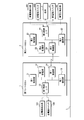
- FIG. 1 is a schematic view showing a configuration of a power supply system for a vehicle seat according to a first embodiment.
- FIG. 1 is a block diagram showing a configuration of a power supply device for a vehicle seat according to a first embodiment. It is an explanatory view showing an example about state transition of charge and discharge of an electrical storage part. It is explanatory drawing which shows an example regarding the load table in each load. It is a flowchart which shows the process of the 2nd control part which concerns on Embodiment 1 (basic form). It is a flowchart which shows the process of the 2nd control part which concerns on Embodiment 2 (output voltage of a vehicle-mounted battery).
- the vehicle seat is provided with a plurality of loads as well as a motor for moving the vehicle seat. Therefore, when driving a plurality of loads simultaneously, there is a problem that the power that can be supplied by the power supply device described in Patent Document 1 may be insufficient for the power for driving the plurality of loads simultaneously.
- An object of the present disclosure is to provide a vehicle seat power supply device capable of supplying power corresponding to a plurality of loads provided to a seat when supplying power to a load provided to a seat in a noncontact manner.
- a power supply device for a vehicle seat is provided on the vehicle seat, and a power reception unit connected to a plurality of loads in the vehicle seat and power without contact to the power reception unit
- the power transmission unit includes: a power transmission unit configured to transmit power; and a power storage unit provided in the vehicle seat, connected to the load, and charged via a power feeding path by the power reception unit and the power transmission unit.
- the storage unit provided in the vehicle seat is connected to the load, power can be supplied to the load from the storage unit. Therefore, the power corresponding to the load can be supplied by the power supplied from the power transmission unit and the power supplied from the power storage unit.
- a switching unit is provided between the power receiving unit and the storage unit, and the storage unit is charged with respect to the load or the load that is charged via the power feeding path by switching the switching unit. It is preferable to be in a discharge state for supplying power.
- the switching unit switches the storage unit to the charging state or the discharging state based on the load power and the feeding power, so that charging and discharging of the storage unit can be performed accurately.
- the switching unit switches the storage unit to the discharging state when the load power is larger than the feeding power, and switches the storage unit to the charging state when the load power is less than the feeding power. preferable.
- the switching unit switches to the discharging state when the load power is larger than the feeding power, and switches to the charging state when the load power is less than the feeding power, so that the charging and discharging to the power storage unit can be accurately performed.
- An output voltage detection unit that detects an output voltage of the storage unit, the switching unit switches the storage unit to the charge state or the discharge state based on the output voltage detected by the output voltage detection unit.
- the configuration is preferred.
- the switching unit switches the storage unit to the charged state or the discharged state based on the output voltage of the storage unit, so that charging and discharging of the storage unit can be performed accurately.
- the switching unit preferably switches the power storage unit to the charging state when the output voltage of the power storage unit is equal to or less than a predetermined value.
- the switching unit switches the storage unit to the charged state, and therefore, the storage unit can be prevented from being overdischarged.
- a load power derivation unit for deriving load power for driving the load, a feed power detection unit for detecting feed power fed via the feed path, and output power of the storage unit An output power detection unit, wherein, when the load power is larger than a total power of the feed power and the output power, load power of one or more loads which are simultaneously executed is smaller than the total power; It is preferable to include a control unit that performs control to make the timing of driving the load different.
- the control unit drives the load such that the load power of one or more loads simultaneously executed becomes smaller than the total power. Timing can be made different to cope with driving of these loads.
- control unit sequentially controls the driving of the load based on the driving priority of each of the loads.
- the control unit sequentially drives and controls the loads based on the respective drive priorities of the loads, so that the load is simultaneously driven.
- the load power can be reduced below the total power to accommodate the driving of these loads.
- a second output voltage detection unit that detects the output voltage of the on-board battery that supplies power to the power transmission unit, and the output voltage of the on-vehicle battery detected by the second output voltage detection unit is less than a predetermined value It is preferable to have a configuration including a feed stop unit that stops the feeding of power from the power transmission unit to the power reception unit.
- the power supply stop unit stops power supply from the power supply unit to the power reception unit.
- the load can be driven by supplying electric power from the power storage unit to the load while suppressing the problem.
- FIG. 1 is a schematic view showing a configuration of a power supply system for a vehicle seat according to a first embodiment.
- FIG. 2 is a block diagram showing the configuration of a power feeding device K for a vehicle seat according to the first embodiment.
- the power feeding system is mounted on the vehicle C, and a power transmission unit including the first sheet ECU 1 and the plurality of power transmission coils 102 provided on the vehicle floor F, and the second sheet ECU 2 and the plurality of power receiving coils provided on the sheet S.
- a power receiving unit including 202.
- the seat S for example, a motor for sliding and moving the seat S, a driving unit such as a motor for reclining the backrest of the seat S, or a plurality of seat heaters for varying the surface temperature of the seat S Load 3 is provided.
- the seat S is a slide seat for a vehicle configured to move along a rail R provided on a vehicle body floor F by control of a second seat ECU 2 described later.
- the rail R is not limited to an I-shaped straight shape, and may include, for example, a curved portion such as a J-shape or a U-shape.
- the seat S provided at the front of the vehicle C does not have to always face forward, and is guided along, for example, a J-shaped rail R , Is moved to turn backwards.
- a plurality of power transmission coils 102 are disposed along the vicinity of the rails R in correspondence with the disposition of the rails R. Alternatively, the plurality of power transmission coils 102 may be provided inside the rail R.
- the plurality of power transmission coils 102 are connected in parallel to each other, and both ends thereof are connected to the DC / AC converter 5.
- the DC / AC converter 5 is connected to the in-vehicle battery 7, converts the DC voltage output from the in-vehicle battery 7 into an AC voltage, and outputs the converted AC voltage to each of the plurality of power transmission coils 102.
- the number of DC / AC converters 5 is not limited to one, and may be plural.
- the plurality of transmission coils 102 are grouped according to the number of DC / AC converters 5 and the transmission coils 102 for each group are connected to the individual DC / AC converters 5 It may be
- a power transmission switch 103 is provided between the DC / AC converter 5 and each of the plurality of power transmission coils 102.
- the power transmission side switch 103 is, for example, a semiconductor switch such as an n-type FET. Alternatively, the power transmission side switch 103 may be a mechanical relay. By turning on or off the power transmission side switch 103, connection or disconnection between the DC / AC converter 5 and the power transmission coil 102 is performed.
- Each power transmission coil 102 is provided with a power transmission side detection unit 101 that detects a value related to the power output by the power transmission coil 102, such as a voltage value, current value, power value or magnetic flux density for each power transmission coil 102.
- the power transmission side detection unit 101 is configured of, for example, a shunt resistor or a Hall element.
- the first sheet ECU 1 obtains the detection results output from the respective power transmission side detection units 101, and turns on or off the respective power transmission side switches 103, thereby outputting the DC / AC converter 5 for the power transmission coil 102. Control the supply of AC voltage.
- a plurality of power receiving coils 202 are provided at predetermined intervals. It is desirable that the power receiving coil 202 be provided below the seat portion of the seat S so that the distance to the vehicle body floor F, that is, the distance to the power transmitting coil 102 is reduced.
- the plurality of receiving coils 202 are connected in parallel to each other, and both ends thereof are connected to the AC / DC converter 6.
- the AC / DC converter 6 is connected to a plurality of loads 3 connected in parallel to each other, converts the AC voltage received by the power receiving coil 202 into a DC voltage, and outputs the converted DC voltage to the plurality of loads 3 Do.
- the number of AC / DC converters 6 is not limited to one, and may be plural.
- the plurality of power receiving coils 202 are divided into groups according to the number of AC / DC converters 6, and the power receiving coils 202 for each group are connected to the respective AC / DC converters 6. It may be
- a power receiving switch 203 is provided between the AC / DC converter 6 and each of the plurality of power receiving coils 202.
- the power receiving side switch 203 is, for example, a semiconductor switch such as an n-type FET. Alternatively, the power receiving side switch 203 may be a mechanical relay. By turning on or off the power receiving side switch 203, connection or disconnection between the AC / DC converter 6 and the power receiving coil 202 is performed.
- Each of the power receiving coils 202 is provided with a power receiving side detection unit 201 that detects a value related to the power output from the power receiving coil 202, such as a voltage value, current value, power value or magnetic flux density for each power receiving coil 202.
- the power receiving side detection unit 201 is configured of, for example, a shunt resistor or a Hall element.
- the second sheet ECU 2 acquires the detection results output from the respective power receiving side detection units 201, and turns on or off the respective power receiving side switches 203 to thereby receive power receiving coils connected to the AC / DC converter 6.
- Switch 202 The power receiving coil 202 connected to the AC / DC converter 6 becomes the power receiving coil 202 transmitted from the power transmitting coil 102.
- the first seat ECU 1 communicates with the second seat ECU 2 based on, for example, an instruction signal from a body ECU (not shown) that controls the entire vehicle C, and the second seat ECU 2 is a load provided on the seat S. Control to drive 3 is performed.
- a power storage unit 4 is provided in the sheet S.
- the storage unit 4 is a device that stores electric power, such as a battery such as a lithium ion battery or a capacitor.
- the fully charged output voltage (rated value) from the storage unit 4 is set such that the output voltage from the on-vehicle battery 7 is substantially the same, and is, for example, approximately 12 V.
- the storage unit 4 is connected to the AC / DC converter 6 via the storage unit switch 41, and is charged by the DC voltage output from the AC / DC converter 6.
- the storage unit switch 41 is configured to connect the storage unit 4 and the load 3. That is, the storage unit 4 is configured to be switched by the storage unit switch 41 between the charging state connected to the AC / DC converter 6 and the discharging state connected to the load 3.
- the storage unit switch 41 is further configured to be switched to a state where the storage unit 4 is not connected to any of the load 3 and the AC / DC converter 6, that is, to a disconnected state. Therefore, by switching of the storage unit switch 41, the storage unit 4 is configured to be in a charged state, a discharged state, or a disconnected state.
- the storage unit switch 41 is formed of, for example, a semiconductor switch such as a mechanical relay or an n-type FET.
- connection with the second sheet ECU 2 is directly connected from the power storage unit 4 to the second sheet ECU 2 without passing through the storage unit switch 41, and power is always supplied from the power storage unit 4 to the second sheet ECU 2 You may configure it. Even when power feeding from the power feeding path is interrupted, driving of the second seat ECU 2 can be continued by always connecting the second seat ECU 2 and the storage unit 4.
- a stored voltage detection unit 42 is provided between the storage unit 4 and the storage unit switch 41, and the stored voltage detected by the stored voltage detection unit 42, that is, the voltage value that can be output by the storage unit 4 is It is output to the second seat ECU 2.
- the second sheet ECU 2 controls switching of the storage unit switch 41 based on the acquired stored voltage and the like, and charges the storage unit 4, discharges the storage unit 4 to the load 3 (output of power) or Control to separate the
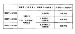
- FIG. 3 is an explanatory view showing an example regarding the state transition of charge and discharge of the power storage unit 4.
- a predetermined value for preventing overdischarge is determined, and the predetermined value is stored in a predetermined storage area such as a second storage unit 22 of a second sheet ECU 2 described later.
- the predetermined value for preventing overdischarge may be, for example, a discharge end-to-end voltage determined based on the battery characteristics of power storage unit 4 or a value determined based on the discharge end-to-end voltage. It may be a doubled value. As shown in FIG.
- the storage unit 4 when the feed power supplied via the feed path is larger than the load power obtained by adding the power consumption of the load 3 to be driven, and the storage unit 4 is not fully charged, the storage unit 4 is charged. Switch to state. When the supplied power is larger than the load power and fully charged, power storage unit 4 may be in the disconnected state. If the stored voltage is smaller than a predetermined value and the supplied power is equal to or less than the load power, storage unit 4 is switched to the disconnected state. If the stored voltage is equal to or higher than the predetermined value and the supplied power is equal to or smaller than the load power, storage unit 4 is switched to the discharged state. If the stored voltage is equal to or higher than a predetermined value and the feed power and the load power are equal, storage unit 4 may be in a disconnected state.
- the stored voltage which is the output voltage of the storage unit 4 relates to the remaining amount of power stored in the storage unit 4, and thus based on the magnitude relationship between the stored voltage in the storage unit 4 and the feed power and the load power. Power storage unit 4 can be appropriately charged and discharged.
- the first seat ECU 1 includes a first control unit 11, a first storage unit 12, a first communication unit 13, a first wireless unit 14, and a first control interface 15.
- the first control unit 11 is configured of a central processing unit (CPU) or a micro processing unit (MPU), etc., and reads and executes control programs and data stored in advance in the first storage unit 12. Control processing and arithmetic processing are performed.
- the first storage unit 12 is configured of a volatile memory element such as RAM (Random Access Memory) or a non-volatile memory element such as ROM (Read Only Memory), EEPROM (Electrically Erasable Programmable ROM) or flash memory.
- RAM Random Access Memory
- ROM Read Only Memory
- EEPROM Electrical Erasable Programmable ROM
- flash memory flash memory.
- the control program and data to be referred to at the time of processing are stored in advance.
- the control program stored in the first storage unit 12 may store the control program read from a recording medium (not shown) readable by the power feeding device K. Alternatively, the control program may be downloaded from an external computer (not shown) connected to a communication network (not shown) and stored in the first storage unit 12.
- the first communication unit 13 is an input / output interface using a communication protocol such as CAN (Control Area Network), LIN (Local Interconnect Network) or Ethernet (registered trademark), and a body connected to the in-vehicle LAN (L) It mutually communicates with other ECUs (not shown) such as an ECU.
- CAN Controller Area Network
- LIN Local Interconnect Network
- Ethernet registered trademark
- the first wireless unit 14 performs wireless communication according to a predetermined protocol using a wireless signal in the LF band or the UHF band (RF band).
- the first control unit 11 is configured to be able to communicate with the second seat ECU 2 via the first wireless unit 14.
- the first wireless unit 14 may perform wireless communication using WiFi (registered trademark) or Bluetooth (registered trademark) or the like.
- the first control interface 15 is connected to the power transmission side detection unit 101 and various sensors (not shown) by a serial cable or the like, and acquires the detection result output from the power transmission side detection unit 101 or the like. Send to In addition, the first control interface 15 is electrically connected to the power transmission side switch 103, and based on the control instruction transmitted from the first control unit 11, a signal for turning on or off the power transmission side switch 103 Output.
- the second seat ECU 2 includes a second control unit 21, a second storage unit 22, a second wireless unit 24, and a second control interface 25. Furthermore, the second seat ECU 2 may be provided with a second communication unit 23.
- the second control unit 21 is configured by a central processing unit (CPU), a micro processing unit (MPU), or the like as the first control unit 11, and the control program and data stored in advance in the second storage unit 22 are Various control processing and arithmetic processing are performed by reading out and executing.
- CPU central processing unit
- MPU micro processing unit
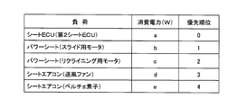
- the second storage unit 22 has the same configuration as that of the first storage unit 12, and stores in advance a control program and data to be referred to during processing. Data relating to the power consumption of each of the loads 3 to be driven and the priority order for determining the order of driving are stored in the second storage unit 22, and these data are, for example, (See FIG. 4).
- the second wireless unit 24 has the same configuration as the first wireless unit 14.
- the second control unit 21 is configured to be able to communicate with the first seat ECU 1 via the second wireless unit 24.
- the second communication unit 23 has the same configuration as the first communication unit 13. However, by communicating with the first seat ECU 1 using the second wireless unit 24, the second communication unit 23 may not be required.
- the second control interface 25 is connected to the power transmission side detection unit 101, the stored voltage detection unit 42, and various sensors (not shown) by a serial cable or the like, and the power transmission side detection unit 101, the stored voltage detection unit 42, etc. The detected result is acquired and transmitted to the second control unit 21.
- the second control interface 25 is electrically connected to the power receiving side switch 203, and outputs a signal for turning on or off the power receiving side switch 203 based on the control instruction transmitted from the second control unit 21. .
- the second control interface 25 is electrically connected to the storage unit switch 41, and outputs a signal for switching the storage unit switch 41 based on the control instruction transmitted from the second control unit 21.
- the second control interface 25 is electrically connected to the load 3 provided on the seat S, and based on the control instruction transmitted from the second control unit 21, a signal for driving the load 3 is generated. Output.
- the first sheet ECU 1 or the second sheet ECU 2 executes the control program to turn on / off the power transmission side switch 103 or the power reception side switch 203 to function as a power feeding path switching unit.
- the first sheet ECU 1 and the second sheet ECU 2 may function as a power supply path switching unit by turning on and off the power transmission side switch 103 and the power reception side switch 203 in cooperation.
- a power feeding path is formed by the power transmission coil 102 and the power reception coil 202 corresponding to the power transmission side switch 103 and the power reception side switch 203 which are turned on. That is, the feed path switching unit switches the feed path.
- the first control unit 11 of the first sheet ECU 1 or the second control unit 21 of the second sheet ECU 2 executes the control program based on the detection result from the power transmission side detection unit 101 or the power reception side detection unit 201. It functions as a feeding power detection unit that detects feeding power by the power transmission coil 102 and the power receiving coil 202 that form a power feeding path.
- the second control unit 21 of the second seat ECU 2 functions as a control unit that drives and controls the plurality of loads 3 provided on the seat S by executing the control program.
- Each of the loads 3 includes a drive switch (not shown) for starting driving, and the second control unit 21 loads the drive switch by turning the drive switch on or off via the second control interface 25. 3 Control each drive.
- the second control unit 21 of the second seat ECU 2 refers to the load table stored in the second storage unit 22 by executing the control program, and the total value of the power consumption of the load to be driven simultaneously (load power Functions as a load power detection unit that derives.
- FIG. 4 is an explanatory view showing an example of a load table at each load 3.
- the load 3 provided on the seat S is the second seat ECU 2, a slide motor for a power seat, a reclining motor, a blower fan for a seat air conditioner, and a peltier element.
- the power consumption for driving each load is previously determined as a rated value.
- the priority (drive priority) in driving each load is determined.
- the loads are referred to with reference to the load table stored in the second storage unit.
- the respective power consumption and drive priority are derived. If the second control unit 21 drives the load at different timings so that the sum (load power) of the power consumption of a plurality of loads driven simultaneously becomes equal to or less than the sum of the feed power and the output power of the storage unit 4. Let's drive. Furthermore, the second control unit 21 may determine the order of driving the loads based on the drive priority and sequentially drive the loads.
- the second control unit 21 of the second seat ECU 2 executes the control program to detect the output voltage and the output power of the storage unit based on the output voltage (stored voltage) detected by the stored voltage detection unit 42. It functions as a detection unit and an output power detection unit.
- the first control unit 11 of the first seat ECU 1 or the second control unit 21 of the second seat ECU 2 outputs the output voltage of the in-vehicle battery 7 based on the detection result from the power transmission side detection unit 101.
- the first control unit 11 of the first seat ECU 1 or the second control unit 21 of the second seat ECU 2 moves the sheet S when it is slid along the rail R based on, for example, instruction control from the body ECU.
- the position of the sheet S is derived based on the number of rotations or the rotation angle of the motor.
- the first seat ECU 1 or the second seat ECU 2 stores the derived position of the seat S in the first storage unit 12 or the second storage unit 22. That is, the first control unit 11 of the first seat ECU 1 or the second control unit 21 of the second seat ECU 2 functions as a seat position deriving unit that derives the position of the seat S.
- combinations of the power transmission coil 102 and the power reception coil 202 which are the closest distance corresponding to the respective positions of the sheet S are stored.
- a combination of the power transmission coil 102 and the power reception coil 202 may be stored as a table with respect to coordinates indicating the position of the sheet S. Therefore, based on the current position of the sheet S, the first sheet ECU 1 or the second sheet ECU 2 can derive the combination of the power transmission coil 102 and the power reception coil 202 which is the closest distance.
- the coupling coefficient of the electromagnetic induction is determined in inverse proportion to the distance between the coils. That is, the shorter the distance, the larger the coupling coefficient. The feed efficiency increases as the coupling coefficient increases.
- the power transmission coil 102 connected to the power transmission switch 103 by the first sheet ECU 1 turning on any power transmission switch 103 and the second sheet ECU 2 turning on any power receiving switch 203; Contactless power feeding is performed between the power receiving side switch 203 and the power receiving coil 202 connected to the power receiving side switch 203 by electromagnetic induction or magnetic field resonance. That is, a feed path is formed by the power transmission coil 102 and the power reception coil 202.
- Each of the plurality of power transmission coils 102 is connected to the on-vehicle battery 7 via the DC / AC converter 5.
- Each of the plurality of receiving coils 202 is connected to the plurality of loads 3 connected in parallel via the AC / DC converter 6. Since the feed path is formed by a combination of any of the power transmission coils 102 and any of the receive coils 202, a plurality of power feed paths can be formed according to this combination. Therefore, even when one of the power transmission coil 102 or the power reception coil 202 fails, the other power transmission coil 102 or the power reception coil 202 is combined to form a power feeding circuit, thereby allowing the on-vehicle battery The power from 7 can be supplied to the load 3 provided in the sheet S in a contactless manner.
- the power supplied via the power supply path is smaller than the load power required to drive the plurality of loads 3 simultaneously, or the power supply path is cut off. Also, by using the output power from power storage unit 4, load 3 can be driven.
- the storage unit switch 41 By switching the storage unit 4 to the charged state, the discharged state, or the disconnected state by the storage unit switch 41, it is possible to appropriately charge the storage unit 4 and prevent over-discharge.
- the load 3 is controlled to be equal to or lower than the output power of the storage unit by changing the timing of driving the load 3 by changing the timing. It can respond appropriately to the drive of 3. Further, by determining the order of driving the loads 3 and sequentially driving the plurality of loads 3, the driving of the loads 3 can be appropriately coped with.
- the first sheet ECU 1 or the second sheet ECU 2 specifies a power feeding path that exhibits a predetermined power feeding efficiency based on the detection results from the power transmission side detection unit 101 or the power reception side detection unit 201 or both detection units. And it controls on and off of the power receiving side switch 203, and switches so as to become the power feeding path. Therefore, power feeding performance of the power transmission coil 102 and the power reception coil 202 can be secured. Further, by switching to a feeding circuit with the highest feeding efficiency as the predetermined feeding efficiency, power can be supplied to the load 3 provided on the sheet S more efficiently.
- the first sheet ECU 1 or the second sheet ECU 2 derives a combination of the closest transmitting coil 102 and receiving coil 202 based on the current position of the sheet S.
- the first sheet ECU 1 or the second sheet ECU 2 can efficiently supply power to the load 3 provided on the sheet S by switching to the feed circuit according to the combination of the derived power transmission coil 102 and the received power coil 202.
- Communication between the first control unit 11 of the first seat ECU 1 and the second control unit 21 of the second seat ECU 2 is performed through the first wireless unit 14 and the second wireless unit 24 so that the first seat ECU 1 and the first control unit 11 can communicate with each other. It can be unnecessary to arrange a communication line between itself and the second seat ECU 2. Therefore, in the sheet S provided with the second sheet ECU 2 and the load 3 and the like, both the power feeding system and the communication system can be wireless, and the freedom in movement of the sheet S can be improved.
- the communication between the first control unit 11 and the second control unit 21 is not limited to wireless communication, and may be via the wired first communication unit 13 and the second communication unit 23.
- first seat ECU 1 is described as a separate body from the body ECU, the present invention is not limited to this.
- the first seat ECU 1 may be included in the body ECU, and the function of the first seat ECU 1 may be exhibited as one function of the body ECU.
- the second sheet ECU 2 may have the function of the first sheet ECU 1 and may control on / off of the power transmission side switch 103 connected to the power transmission coil 102 from the second sheet ECU 2 via the communication line. .
- the present invention is not limited to this. It is also possible to switch the feed path by turning on and off either the power transmission coil 102 or the power reception coil 202 side switch 103 or 203 without using any switch of the power transmission side switch 103 or the power reception side switch 203. .
- the power transmission coil 102 may be always connected to the DC / AC converter 5, and the power reception coil 202 may be always connected to the AC / DC converter 6, and the output voltage from the on-vehicle battery 7 may always be output (applied) to the load 3. .
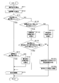
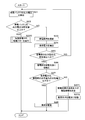
- FIG. 5 is a flowchart showing processing of the second control unit 21 according to the first embodiment.
- the second control unit 21 of the second seat ECU 2 acquires a control signal for driving the load 3 in the seat S
- the second control unit 21 starts the following process.
- the second control unit 21 may periodically start the following process when a switch for starting the vehicle such as an IG (ignition) switch is turned on, and at predetermined time intervals thereafter.
- the second control unit 21 starts the following process by changing the positional relationship between the power transmission coil 102 and the power reception coil 202 by moving the sheet S, that is, moving the sheet S. You may
- the second control unit 21 derives load power (S11).
- the second control unit 21 acquires, for example, a signal relating to a drive instruction of the load 3 provided on the seat S from the body ECU via the first seat ECU 1. This signal is transmitted from the body ECU based on the operation of the vehicle operator.
- the operator executes a plurality of loads 3 simultaneously, for example, operating the reclining power seat after turning on the seat air conditioner. Should occur. Therefore, when the second seat ECU 2 receives an instruction to drive a plurality of loads 3, the second seat ECU 2 derives the total value of the power consumption of the loads 3.
- the second control unit 21 may use the power consumption of the load 3 already driven.
- the sum value of the power consumption of the load 3 targeted for the drive instruction is derived.
- the second control unit 21 refers to the load table stored in a predetermined storage area such as the second storage unit 22 or the like, and adds the sum value of the power consumption of each of the three target loads. Derivate as load power.
- the second control unit 21 detects the feed power (S12).
- the second control unit 21 derives, based on the detection result from the power receiving side detection unit 201, the power received by the power receiving coil 202, that is, the feeding power to be fed via the feeding path.
- the second control unit 21 may derive feed power based on the detection result of a power meter (not shown) that detects DC power output from the AC / DC converter 6.
- the second control unit 21 determines whether the feed power is equal to or higher than the load power (S13). When the feed power is equal to or higher than the load power (S13: YES), all the loads 3 to be driven can be driven by the feed power.
- the second control unit 21 determines whether the power storage unit 4 is in a fully charged state (S14). When the storage unit 4 determines the fully charged state, for example, the second control unit 21 compares the output voltage (discharge voltage) of the storage unit 4 detected by the stored voltage detection unit 42 and the output voltage in the fully charged state. In comparison, it is determined whether the battery is fully charged.
- second control unit 21 switches power storage unit 4 to the charged state (S141).
- the second control unit 21 switches the storage unit switch 41 so that the storage unit 4 and the AC / DC converter 6 are connected, and the storage unit 4 is in a charging state.
- the second control unit 21 drives the load 3 to be driven (S15).
- the second control unit 21 starts driving the load 3 by turning on a load drive switch included in the configuration of the load 3 or connected in series with the load 3.
- second control unit 21 drives load 3 to be driven (S15).
- the second control unit 21 may switch the storage unit switch 41 so that the storage unit 4 is disconnected to neither the AC / DC converter 6 nor the load 3.
- the second control unit 21 determines whether the output voltage of the storage unit 4 is equal to or higher than a predetermined value (S131).
- the predetermined value is, for example, an output voltage of storage unit 4 at least necessary for driving load 3 or a predetermined voltage value defined to prevent storage unit 4 from being overdischarged. It is a value corresponding to the storage residual amount of 4.
- second control unit 21 switches power storage unit 4 to the discharged state (S132).
- the second control unit 21 switches the storage unit switch 41 so that the storage unit 4 and the load 3 are connected, power is supplied from the storage unit 4 to the load 3, and the storage unit 4 is in a discharged state.
- the second control unit 21 determines whether the load power is equal to or less than the total power of the feed power and the output power of the storage unit 4 (S133). If the load power is equal to or less than the total power (S133: YES), the second control unit 21 drives the load 3 to be driven (S15).
- the second control unit 21 determines the driving order of each of the loads 3 to be driven (S1331). Then, the second control unit 21 sequentially drives each of the loads 3 based on the determined driving order (S1332).
- the second control unit 21 refers to the load table stored in the second storage unit 22 and reads the power consumption of each of the three loads to be driven and the drive priority. Then, the second control unit 21 determines the drive order of the load 3 so that the total value of the power consumption of the load 3 simultaneously executed becomes equal to or less than the total power according to the drive priority order.
- the feed power is 45 W
- the output power from the storage unit 4 is 45 W.
- the voltage of the feeding power and the output power from the storage unit 4 is set to, for example, approximately 12V.
- the load 3 to be driven is, for example, the second seat ECU 2 (a [W]), a slide motor (b [W]), a reclining motor (c [W]), a blower fan (d [W]), and a Peltier element It is assumed that (e [W]).
- the loads 3 to be driven are sequentially driven, that is, the timings at which the loads 3 to be driven are performed are made different to cope with the driving of a plurality of loads 3. be able to.
- the load power may be equal to or less than the total power by alternately driving these two loads 3.
- the load power by the plurality of loads 3 is equal to or less than the total power
- the loads 3 are simultaneously executed, but the present invention is not limited thereto.
- the load power of the plurality of loads 3 is equal to or less than the total power
- the loads 3 may be driven individually and sequentially according to the priority. Needless to say, the priority of the second seat ECU 2 is the highest with respect to the other loads 3 and the second seat ECU 2 should always be driven.
- second control unit 21 converts storage unit 4 into AC / DC converter 6 and It switches to the disconnected state which is not connected to any of the loads 3 (S1311). By switching the storage unit 4 to the disconnected state, overdischarge of the storage unit 4 can be prevented.
- the second control unit 21 determines the drive order of each of the loads 3 to be driven as in the process of (S133: NO) (S1331). Then, the second control unit 21 sequentially drives each of the loads 3 based on the determined driving order (S1332). However, in this case, since power storage unit 4 is disconnected, the feed power supplied via the feed path is the total power. Therefore, when driving the load 3, the upper limit of the power consumption is further lowered. Therefore, for example, the driving of the load 3 of larger power consumption than the predetermined power consumption, such as the Peltier element with the largest power consumption, is prohibited, the driving priorities of the other loads 3 are determined, and these loads 3 are sequentially May be driven.
- the driving of the slide motor is started and stopped while the second seat ECU 2 is driven, and then the driving of the reclining motor is started and stopped next. After that, the blower fan may be driven, and these loads 3 may be sequentially driven.
- power storage unit 4 By switching the charge state or the discharge state of power storage unit 4 based on the output voltage from power storage unit 4, power storage unit 4 can be appropriately charged. In addition, overcharging of power storage unit 4 can be prevented.
- the load power which is the sum of the power consumption of the load 3 to be driven
- the load The order of driving the loads 3 is determined based on the driving priority of 3, and the loads 3 are sequentially driven, that is, driven at different driving timings. Therefore, the total value of the power consumption of the loads 3 driven simultaneously can be made equal to or less than the total power, and the drive of these loads 3 can be handled. Since load 3 is sequentially driven in accordance with the sum of the feed power and the output power of storage unit 4, storage unit 4 can be miniaturized.
- the second control unit 21 of the second seat ECU 2 provided inside the seat S is mainly described, but the present invention is not limited to this.
- the process according to the first embodiment may be mainly performed by the first control unit 11 of the first seat ECU 1.
- the first control unit 11 and the second control unit 21 communicate, the first control unit 11 and the second control unit 21 cooperate to perform the processing according to the first embodiment. May be
- FIG. 6 is a flowchart illustrating the process of the second control unit 21 according to the second embodiment.
- the second control unit 21 of the second seat ECU 2 starts the following process, as in the first embodiment.
- the second control unit 21 detects the output voltage of the in-vehicle battery 7 (S21).
- the second control unit 21 communicates with the first control unit 11 of the first seat ECU 1, and detects the output voltage of the on-board battery 7 based on the detection result of the power transmission side detection unit 101.
- the second control unit 21 obtains the detection result of a voltmeter (not shown) for detecting the output voltage of the in-vehicle battery 7 or the DC / AC converter 5 through the first control unit 11, and outputs the output of the in-vehicle battery 7.
- the voltage may be detected.
- the second control unit 21 determines whether the output voltage of the in-vehicle battery 7 is equal to or higher than a predetermined value (S22).
- the predetermined value is, for example, an output voltage of the on-board battery 7 at least necessary for driving the load 3 or a predetermined voltage value defined to prevent the on-board battery 7 from being overdischarged. Value corresponding to the remaining charge amount of
- the second control unit 21 performs the process according to the same flow as that of the first embodiment (S220).
- the second control unit 21 shuts off the power feeding path (S23). In order to cut off the power feeding path, the second control unit 21 turns off all the power receiving switches 203 connected to the power receiving coil 202. Alternatively, the second control unit 21 turns off all of the power transmission side switches 103 connected to the power transmission coil 102 by communicating with the first control unit 11 of the first seat ECU 1. Alternatively, the switch of the AC / DC converter 6 may be turned off, or the switch (not shown) connected between the AC / DC converter 6 and the on-vehicle battery 7 may be turned off.
- the second control unit 21 derives load power as in the process S11 of the first embodiment (S24).
- the second control unit 21 determines whether the output voltage of the storage unit 4 is equal to or higher than a predetermined value as in step S131 of the first embodiment (S25).
- the second control unit 21 performs a loop process to execute the process of S21 again. That is, the second control unit 21 stands by without driving the load 3 until the output voltage of the in-vehicle battery 7 is recovered. Even in such a state, the supply of power from power storage unit 4 to second sheet ECU 2 is continued.
- the power consumption of the second sheet ECU 2 is mainly the drive power of the MPU of the second control unit 21, but the power consumption is smaller compared to other loads 3 such as a slide motor. Therefore, when there is no power feeding from the power feeding path, the second seat ECU 2 is configured to always be supplied with the power from the power storage unit 4.
- the second control unit 21 switches the storage unit 4 to the discharge state as in step S132 of the first embodiment (S26).
- the second control unit 21 executes the processes of S27, S271, S272, and S28 in the same manner as the processes of S133, S1331, S1332, and S15 of the first embodiment.
- the load 3 is driven only by the electric power stored in the power storage unit 4, and the upper limit of the power consumption is further lowered. . Therefore, as compared with the case where power feeding is performed from the power feeding path as in the first embodiment, the load 3 which inhibits driving may be further set.
- the power storage unit 4 supplies power to the loads 3 and the load 3 can be driven.
- the driving order of the loads 3 is determined so that the load power of the loads 3 driven simultaneously becomes equal to or less than the output power of the storage unit 4, and these loads 3 are sequentially driven to store electricity.
- the part 4 can be miniaturized.
- the first control unit 11 is mainly used, or the first control unit 11 and the second control unit 21 cooperate to perform the processing according to the second embodiment. It may be.
Landscapes
- Engineering & Computer Science (AREA)
- Power Engineering (AREA)
- Computer Networks & Wireless Communication (AREA)
- Mechanical Engineering (AREA)
- Chemical Kinetics & Catalysis (AREA)
- General Chemical & Material Sciences (AREA)
- Electrochemistry (AREA)
- Chemical & Material Sciences (AREA)
- Manufacturing & Machinery (AREA)
- Aviation & Aerospace Engineering (AREA)
- Transportation (AREA)
- Charge And Discharge Circuits For Batteries Or The Like (AREA)
- Seats For Vehicles (AREA)
- Secondary Cells (AREA)
Priority Applications (2)
| Application Number | Priority Date | Filing Date | Title |
|---|---|---|---|
| US16/964,322 US11345257B2 (en) | 2018-01-23 | 2019-01-16 | Power supply device for vehicle seat |
| CN201980007562.XA CN111565972A (zh) | 2018-01-23 | 2019-01-16 | 车辆用座椅的供电装置 |
Applications Claiming Priority (2)
| Application Number | Priority Date | Filing Date | Title |
|---|---|---|---|
| JP2018009176A JP7003684B2 (ja) | 2018-01-23 | 2018-01-23 | 車両用シートの給電装置 |
| JP2018-009176 | 2018-01-23 |
Publications (1)
| Publication Number | Publication Date |
|---|---|
| WO2019146455A1 true WO2019146455A1 (ja) | 2019-08-01 |
Family
ID=67395469
Family Applications (1)
| Application Number | Title | Priority Date | Filing Date |
|---|---|---|---|
| PCT/JP2019/000980 Ceased WO2019146455A1 (ja) | 2018-01-23 | 2019-01-16 | 車両用シートの給電装置 |
Country Status (4)
| Country | Link |
|---|---|
| US (1) | US11345257B2 (enExample) |
| JP (1) | JP7003684B2 (enExample) |
| CN (1) | CN111565972A (enExample) |
| WO (1) | WO2019146455A1 (enExample) |
Cited By (1)
| Publication number | Priority date | Publication date | Assignee | Title |
|---|---|---|---|---|
| WO2022054931A1 (ja) * | 2020-09-10 | 2022-03-17 | Apb株式会社 | リチウムイオン電池のリサイクル方法、リサイクル設備、乗物用座席及びその製造方法 |
Families Citing this family (12)
| Publication number | Priority date | Publication date | Assignee | Title |
|---|---|---|---|---|
| JP2021036751A (ja) | 2019-08-30 | 2021-03-04 | 株式会社オートネットワーク技術研究所 | 給電システム |
| JP6957577B2 (ja) * | 2019-11-05 | 2021-11-02 | 日本たばこ産業株式会社 | エアロゾル吸引器用の電源ユニット |
| WO2021102310A1 (en) * | 2019-11-21 | 2021-05-27 | Ge Hybird Technologies, Llc | Aggregated wireless power transfer with multiple coils and communication channels |
| KR102729870B1 (ko) * | 2019-12-13 | 2024-11-14 | 현대자동차주식회사 | 배터리 자동 충전이 가능한 이동식 시트 제어 장치 |
| CN112018907B (zh) * | 2020-10-14 | 2021-04-06 | 广东希荻微电子股份有限公司 | 一种充电模块及双模无线充电系统 |
| EP4005866B1 (de) * | 2020-11-30 | 2023-07-12 | IMS Gear SE & Co. KGaA | Sitzlängsverstellvorrichtung, verfahren zum verstellen eines sitzes und kraftfahrzeug mit ebensolcher sitzlängsverstellvorrichtung |
| JP7783494B2 (ja) * | 2021-03-29 | 2025-12-10 | 株式会社デンソーウェーブ | 充電システム |
| KR102462446B1 (ko) * | 2021-04-08 | 2022-11-03 | 대원산업 주식회사 | 배터리 내장형 시트 장치와, 배터리 내장형 시트 시스템 및 배터리 내장형 시트 장치의 충전 방법 |
| DE102022202434A1 (de) | 2022-03-10 | 2023-09-14 | Brose Fahrzeugteile SE & Co. Kommanditgesellschaft, Coburg | Verstellsystem für einen Fahrzeugsitz und Verfahren zum Verstellen eines Fahrzeugsitzes |
| WO2023178043A2 (en) * | 2022-03-16 | 2023-09-21 | Yank Technologies, Inc. | Wireless charging feedback and communication system for vehicles |
| CN115179825B (zh) * | 2022-07-11 | 2024-06-25 | 欧颂科技(海南)有限公司 | 带有安全供电系统的儿童电动安全座椅 |
| JP2024148192A (ja) * | 2023-04-05 | 2024-10-18 | 株式会社デンソー | 非接触給電システム、コンピュータプログラム、受電装置および送電装置 |
Citations (2)
| Publication number | Priority date | Publication date | Assignee | Title |
|---|---|---|---|---|
| JPH10285837A (ja) * | 1997-04-08 | 1998-10-23 | Trw Vehicle Safety Syst Inc | 車両の部品間で電気伝達を行うための装置 |
| JP2006056440A (ja) * | 2004-08-23 | 2006-03-02 | Nissan Motor Co Ltd | 乗員保護装置 |
Family Cites Families (19)
| Publication number | Priority date | Publication date | Assignee | Title |
|---|---|---|---|---|
| JPH0692166A (ja) * | 1992-09-14 | 1994-04-05 | Delta Kogyo Co Ltd | 電動シート装置 |
| JPH08251713A (ja) * | 1995-03-15 | 1996-09-27 | Yamaha Motor Co Ltd | 電動車の電流制御装置 |
| US6195603B1 (en) * | 1995-08-11 | 2001-02-27 | Lear Corporation | Multiple speed vehicle seat memory control apparatus |
| EP1859525A4 (en) * | 2005-03-08 | 2015-08-12 | Dura Global Tech Inc | ELECTRONIC CONTROL SYSTEM WITH TORQUE AND / OR SPEED INCREASE FOR MOTOR VEHICLE SEATS |
| JP4804185B2 (ja) * | 2006-03-24 | 2011-11-02 | 株式会社オーテックジャパン | 車両用シートの昇降速度可変スイッチ |
| JP2008289273A (ja) * | 2007-05-17 | 2008-11-27 | Toyota Motor Corp | 給電システムおよび車両 |
| EP2476574B1 (en) * | 2009-09-09 | 2014-10-22 | Toyota Jidosha Kabushiki Kaisha | Power supply system for vehicle and method of controlling same |
| US20130002415A1 (en) * | 2011-06-28 | 2013-01-03 | Geotab Inc. | Vehicular telematics device with voltage sensor-predicated GPS reciever activation |
| JP6111536B2 (ja) * | 2012-06-01 | 2017-04-12 | マツダ株式会社 | 車両用電源制御方法及び装置 |
| JP5998755B2 (ja) * | 2012-08-30 | 2016-09-28 | マツダ株式会社 | 車両用電源制御装置および方法 |
| JP5825269B2 (ja) * | 2013-01-24 | 2015-12-02 | トヨタ自動車株式会社 | 車両用電源装置 |
| JP2014172162A (ja) * | 2013-03-13 | 2014-09-22 | Panasonic Corp | 電動工具 |
| JP6310258B2 (ja) | 2014-01-16 | 2018-04-11 | 矢崎総業株式会社 | スライドシートの給電機構 |
| WO2015159388A1 (ja) * | 2014-04-16 | 2015-10-22 | 三菱電機株式会社 | 制御装置、制御システム、制御方法及びプログラム |
| JP2015217919A (ja) * | 2014-05-21 | 2015-12-07 | オムロンオートモーティブエレクトロニクス株式会社 | 車両用電源装置、車両用回生システム |
| JP6353746B2 (ja) * | 2014-08-26 | 2018-07-04 | 矢崎総業株式会社 | 車両用電源制御システム、ワイヤハーネス及び車両用電源制御装置 |
| US10536100B2 (en) * | 2016-04-01 | 2020-01-14 | Gentherm Incorporated | Systems and methods for calculating motor position, inertia and rest position in sensorless brushed DC motor control systems |
| EP3276768B1 (de) * | 2016-07-29 | 2019-04-24 | Ford Global Technologies, LLC | Elektrisches bordnetzsystem für kraftfahrzeuge mit einem konverter und einem hochlastverbraucher |
| KR102410936B1 (ko) * | 2017-04-04 | 2022-06-20 | 현대자동차주식회사 | 차량 모터 제어 장치 및 방법 |
-
2018
- 2018-01-23 JP JP2018009176A patent/JP7003684B2/ja active Active
-
2019
- 2019-01-16 US US16/964,322 patent/US11345257B2/en active Active
- 2019-01-16 CN CN201980007562.XA patent/CN111565972A/zh active Pending
- 2019-01-16 WO PCT/JP2019/000980 patent/WO2019146455A1/ja not_active Ceased
Patent Citations (2)
| Publication number | Priority date | Publication date | Assignee | Title |
|---|---|---|---|---|
| JPH10285837A (ja) * | 1997-04-08 | 1998-10-23 | Trw Vehicle Safety Syst Inc | 車両の部品間で電気伝達を行うための装置 |
| JP2006056440A (ja) * | 2004-08-23 | 2006-03-02 | Nissan Motor Co Ltd | 乗員保護装置 |
Cited By (1)
| Publication number | Priority date | Publication date | Assignee | Title |
|---|---|---|---|---|
| WO2022054931A1 (ja) * | 2020-09-10 | 2022-03-17 | Apb株式会社 | リチウムイオン電池のリサイクル方法、リサイクル設備、乗物用座席及びその製造方法 |
Also Published As
| Publication number | Publication date |
|---|---|
| CN111565972A (zh) | 2020-08-21 |
| JP7003684B2 (ja) | 2022-01-20 |
| US11345257B2 (en) | 2022-05-31 |
| US20200346562A1 (en) | 2020-11-05 |
| JP2019127114A (ja) | 2019-08-01 |
Similar Documents
| Publication | Publication Date | Title |
|---|---|---|
| WO2019146455A1 (ja) | 車両用シートの給電装置 | |
| EP2957016B1 (en) | Hybrid vehicle running control apparatus | |
| US20110304304A1 (en) | Charge controller and method of operating the same | |
| CN105492243B (zh) | 充电系统和配对方法 | |
| CN103813928A (zh) | 电池的处理装置、车辆、电池的处理方法及电池的处理程序 | |
| US9162576B2 (en) | Power switching apparatus | |
| JP5811287B2 (ja) | 車両 | |
| US20160197487A1 (en) | Wireless power receiving device | |
| JP2010259308A (ja) | 電気自動車の充電装置 | |
| US11135925B2 (en) | Vehicle | |
| JP7227779B2 (ja) | 車両 | |
| EP2890586A2 (en) | Electrical storage system | |
| US11173793B2 (en) | Electric power supply system including battery, switching apparatus and control apparatus | |
| JP7249164B2 (ja) | 車両 | |
| WO2019146383A1 (ja) | 車両用シートの給電装置 | |
| US8334679B2 (en) | ACG output voltage control | |
| US11007876B2 (en) | Vehicle | |
| US11660965B2 (en) | Vehicle | |
| US20230104277A1 (en) | Electrified vehicle control during trailer towing | |
| KR101475564B1 (ko) | 전기 자동차의 충전 시스템 및 충전 방법 | |
| KR20130120232A (ko) | 전기 자동차의 충전 방법 | |
| JP2013051822A (ja) | 車両用充電装置 | |
| KR101466437B1 (ko) | 전기 자동차의 충전 방법 및 장치 | |
| CN121043695A (zh) | 外部充电系统 | |
| CN115085353A (zh) | 车辆用通信装置 |
Legal Events
| Date | Code | Title | Description |
|---|---|---|---|
| 121 | Ep: the epo has been informed by wipo that ep was designated in this application |
Ref document number: 19743808 Country of ref document: EP Kind code of ref document: A1 |
|
| NENP | Non-entry into the national phase |
Ref country code: DE |
|
| 122 | Ep: pct application non-entry in european phase |
Ref document number: 19743808 Country of ref document: EP Kind code of ref document: A1 |