WO2019145993A1 - 電動機制御装置及び熱交換器ユニット - Google Patents
電動機制御装置及び熱交換器ユニット Download PDFInfo
- Publication number
- WO2019145993A1 WO2019145993A1 PCT/JP2018/001933 JP2018001933W WO2019145993A1 WO 2019145993 A1 WO2019145993 A1 WO 2019145993A1 JP 2018001933 W JP2018001933 W JP 2018001933W WO 2019145993 A1 WO2019145993 A1 WO 2019145993A1
- Authority
- WO
- WIPO (PCT)
- Prior art keywords
- motor
- control unit
- motors
- switch device
- control device
- Prior art date
- Legal status (The legal status is an assumption and is not a legal conclusion. Google has not performed a legal analysis and makes no representation as to the accuracy of the status listed.)
- Ceased
Links
Images







Classifications
-
- H—ELECTRICITY
- H02—GENERATION; CONVERSION OR DISTRIBUTION OF ELECTRIC POWER
- H02P—CONTROL OR REGULATION OF ELECTRIC MOTORS, ELECTRIC GENERATORS OR DYNAMO-ELECTRIC CONVERTERS; CONTROLLING TRANSFORMERS, REACTORS OR CHOKE COILS
- H02P5/00—Arrangements specially adapted for regulating or controlling the speed or torque of two or more electric motors
- H02P5/46—Arrangements specially adapted for regulating or controlling the speed or torque of two or more electric motors for speed regulation of two or more dynamo-electric motors in relation to one another
Definitions
- the present invention relates to a motor control device and a heat exchanger unit that control the rotation of a motor using a power conversion device including an inverter.
- an air conditioner has a refrigerant circuit in which a compressor, a heat source side heat exchanger, a pressure reducing device, a load side heat exchanger, and the like are connected by refrigerant piping, and the enclosed refrigerant circulates.
- the compressor and the heat source side heat exchanger are provided in the outdoor unit, and the load side heat exchanger is provided in the indoor unit.
- the air conditioner air-conditions the room in which the indoor unit is disposed by circulating the refrigerant in the refrigerant circuit.
- the outdoor unit and the indoor unit each function as a heat exchanger unit including a heat exchanger.
- the outdoor unit of the air conditioning apparatus as described above includes a fan for blowing air to the heat source side heat exchanger and a motor control device for driving the fan.
- the motor control device drives the motor serving as a power source of the fan and rotates the fan to perform heat exchange between the refrigerant and the outside air in the heat source side heat exchanger.
- the motor control device controls the number of rotations of the fan and adjusts the air volume sucked by the fan.
- Some air conditioners have an outdoor unit equipped with a plurality of fans in order to increase the amount of air drawn.
- the outdoor unit on which a plurality of fans are mounted requires a plurality of inverters.
- a technology for driving a plurality of motors by one power conversion device for example, see Patent Document 1.
- three motors are connected in parallel to one power conversion device via a switch device.
- the number of operating fans when controlling the amount of air drawn, the number of operating fans may be switched. For example, the heat exchanger unit reduces the number of operating fans when reducing the amount of air drawn. In addition, the heat exchanger unit becomes unstable in control when the plurality of motors are operated in the low rotation range. Therefore, in the low rotation region, the heat exchanger unit switches to a single-unit operation in which only one electric motor operates so that the plurality of electric motors do not operate.
- Patent Document 1 when the switch device is turned off in order to switch from a state where a plurality of electric motors are in operation to one operation, a surge voltage is generated in the switch device. When a surge voltage is applied to the switch device, there is a problem that the switch device may be damaged and the life thereof may be reduced.
- the present invention has been made to solve the above-described problems, and provides a motor control device and a heat exchanger unit that suppress a surge voltage applied to a switch device and suppress damage and life reduction of the switch device.
- the purpose is
- the motor control device comprises a power conversion device for supplying electric power and supplying three-phase voltage to a plurality of motors connected in parallel with each other, at least between the power conversion device and the motor excluding one unit.
- Switch unit that electrically connects or disconnects by on / off operation, and a control unit that controls the operation of the power conversion device and the switch device, and the control unit is in a state where two or more motors are operating. Therefore, when switching to single-unit operation where only the set motor, which is one set motor, operates, the number of rotations of two or more motors being operated is reduced and then the switch device is turned off. is there.
- the heat exchanger unit when a plurality of motors, a plurality of fans connected to each of the plurality of motors, the above-described motor control device, and two or more motors are operating. And a host control device that transmits a unit switching command to the motor control device when the number of rotations of each of the motors being operated decreases to the reference number of rotations, and the reference number of rotations is two or more motors.
- the intake air volume by multiple fans at the same time is equal to the maximum value of the intake air volume by multiple fans when only one motor is operating, for each rotational speed of two or more motors
- the control unit sets the number of rotations of two or more motors being operated when the number switching instruction is transmitted from the host control device, and then turns off the switch device.
- the rotational speed of the plurality of motors is reduced to reduce the current flowing to the switch device and then the switch device is turned off, the surge voltage applied to the switch device is suppressed to damage the switch device. And it is possible to suppress the decrease in life.
- Embodiment 1 of this invention It is the schematic which illustrated the structure of the air conditioning apparatus which concerns on Embodiment 1 of this invention. It is a control block diagram which illustrated the composition of the motor control device in Embodiment 1 of the present invention. It is a figure which shows an example of a structure of the power converter device shown in FIG. It is a flowchart which shows the process by the high-order control apparatus of FIG. It is a flowchart which shows the one part process by the control part of FIG. It is a time chart which shows the one part process by the control part of FIG. It is a flowchart which shows the one part process by the control part of the motor control apparatus which concerns on Embodiment 2 of this invention.
- FIG. 1 is a schematic view illustrating the configuration of the air conditioning apparatus according to Embodiment 1 of the present invention.
- the air conditioner 100 has an outdoor unit 40 and an indoor unit 50.
- the outdoor unit 40 includes a compressor 41, a four-way valve 42, a heat source side heat exchanger 43, a heat source side expansion device 44, and an accumulator 45.
- the indoor unit 50 has a load side heat exchanger 51. That is, in the air conditioner 100, the compressor 41, the four-way valve 42, the heat source side heat exchanger 43, the heat source side expansion device 44, the load side heat exchanger 51, and the accumulator 45 are connected via the refrigerant pipe 61. Has a circulating refrigerant circuit 60.
- the outdoor unit 40 is provided with a host control device 46, a motor control device 10, a first motor 21, a second motor 22, a first fan 31, and a second fan 32.
- the indoor unit 50 is provided with a load-side fan 52, a fan motor 52a, a load-side upper controller 53, and a load-side motor controller 54.
- the compressor 41 includes, for example, a compressor motor (not shown) driven by an inverter, and sucks and compresses the refrigerant.
- the four-way valve 42 is connected to the compressor 41 and is controlled by the host controller 46 to switch the refrigerant flow path.
- the four-way valve 42 becomes a flow path of a solid line in FIG. 1 during the cooling operation in which the heat source side heat exchanger 43 functions as a condenser and the load side heat exchanger 51 functions as an evaporator.
- the load-side heat exchanger 51 functions as a condenser
- the heat source-side heat exchanger 43 functions as an evaporator.
- the heat source side heat exchanger 43 is, for example, a fin and tube type heat exchanger, and exchanges heat between the refrigerant flowing in the refrigerant circuit 60 and the outside air.
- the heat source side throttling device 44 includes, for example, an electronic expansion valve, and decompresses and expands the refrigerant.
- the accumulator 45 stores excess refrigerant and suppresses the inflow of liquid refrigerant to the compressor 41.
- the motor control device 10 controls the heat exchange capacity of the outdoor unit 40 by controlling the rotational speed of each of the first motor 21 and the second motor 22 and the number of operated motors.
- the first fan 31 and the second fan 32 are attached to the heat source side heat exchanger 43 and blow air to the heat source side heat exchanger 43.
- the first fan 31 is connected to the first electric motor 21 and rotates using the first electric motor 21 as a power source.
- the second fan 32 is connected to the second motor 22 and rotates using the second motor 22 as a power source.
- the rotational speed of the first motor 21 and f 1, the rotational speed of the second electric motor 22 to f 2.
- the rotational speeds of the respective motors become equal. That is, when the conventional two simultaneous operation, is equal to the rotational speed f 1 of the first electric motor 21 and the rotational speed f 2 of the second electric motor 22. Therefore, let f be the number of rotations of the first electric motor 21 and the second electric motor 22 in the normal two-unit simultaneous operation in which each process of the first embodiment is not performed.
- the load-side heat exchanger 51 is, for example, a fin-and-tube type heat exchanger, and exchanges heat between the refrigerant flowing through the refrigerant circuit 60 and the indoor air.
- the first motor 21 and the second motor 22 are driven by an inverter (not shown) provided in the load-side upper controller 53.
- the load side fan 52 rotates with the fan motor 52 a as a power source, and blows air to the load side heat exchanger 51.
- the load-side upper control apparatus 53 controls the operation of the load-side fan 52 via the load-side motor control apparatus 54.
- the load-side motor control device 54 controls the heat exchange capacity of the indoor unit 50 by controlling the number of rotations of the fan motor 52 a.
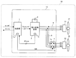
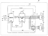
- FIG. 2 is a control block diagram illustrating the configuration of the motor control device according to the first embodiment of the present invention.
- the motor control device 10 drives a plurality of motors connected in parallel to one another.
- the motor control device 10 includes a control unit 1, a DC power supply 2, a power conversion device 3 for converting a DC voltage into a three-phase voltage, and between the power conversion device 3 and the second motor 22.
- a switch device 7 which electrically connects or disconnects the on / off operation.
- the switch device 7 is, for example, a relay, and the first contact portion 7 x connected to one of the three phases of the power conversion device 3 and the other one of the three phases of the power conversion device 3 And a second contact portion 7y connected.
- first contact portion 7 x is connected to the U phase of the three phases of power conversion device 3 and electrically connects or disconnects the U 2 phase power line of three phase power line 9.
- the second contact portion 7y is connected to the W phase of the three phases of the power conversion device 3, and electrically connects or disconnects the W2 phase power line of the three phase power line 9.
- the power conversion device 3 is, for example, an inverter, converts power and supplies three-phase voltages to a plurality of motors connected in parallel to each other.
- the first electric motor 21 and the second electric motor 22 to be controlled by the motor control device 10 are connected in parallel.
- the motor control device 10, the first motor 21, the second motor 22, the first fan 31 and the second fan 32 are included in the heat exchanger unit 30.
- the heat exchanger unit 30 may be the outdoor unit 40 or may be a part of the outdoor unit 40.
- the first motor 21 and the second motor 22 are, for example, brushless DC motors, and are driven by the power converter 3.
- a first fan 31 serving as a load is attached to the first motor 21, and a second fan 32 serving as a load is attached to the second motor 22.
- the first motor 21 is connected to the power converter 3 via the three-phase power line 8.
- the first electric motor 21 directly connected to the power conversion device 3 is set to an electric motor to be operated. That is, the first motor 21 corresponds to the "setting motor" of the present invention.
- the second motor 22 is connected to the power conversion device 3 via a three-phase power line 9 branched from the middle of the three-phase power line 8.
- a switch device 7 is provided between a branch of the three-phase power line 9 with the three-phase power line 8 and the second motor 22.
- Each of the first motor 21 and the second motor 22 has a rotor (not shown) and a stator (not shown) that generates a rotating magnetic field around the rotor according to the applied three-phase voltage.
- the brushless DC motor applies a three-phase AC voltage of appropriate phase and frequency to a stator (not shown) according to the position of the rotor to generate a rotating magnetic field around the rotor, and The rotor is rotated at a desired number of rotations using suction and repulsion with the rotor. At that time, it is necessary to detect the position of the rotor.
- a method of detecting the position of the rotor it is possible to use, for example, a method of detecting by a hall sensor installed in the motor, or a method of calculating by calculation from three-phase current flowing in a known motor.
- the first embodiment exemplifies a case where the motor control device 10 estimates the position of the rotor by the latter method.
- the DC power supply 2 is, for example, a rectifier circuit that converts an AC voltage supplied from a single-phase power supply or a three-phase power supply external to the motor control device 10 into a DC voltage and outputs the DC voltage.
- the power conversion device 3 drives the first electric motor 21 and the second electric motor 22 based on the three-phase voltage command value Vuvw_ref from the control unit 1. That is, the power conversion device 3 performs PWM control by comparing the three-phase voltage command value Vuvw_ref output from the control unit 1 with a carrier wave which is a reference signal not subjected to modulation.
- the control unit 1 acquires the number of revolutions f 1 of the first motor 21 and the number of revolutions f 2 of the second motor 22 over time.
- the control unit 1 performs known vector control based on the rotation speed command value ⁇ _ref input from the upper control device 46 and the detected three-phase current Iuvw, and the power conversion device 3 receives the three-phase voltage command value Vuvw_ref. Output. Further, the control unit 1 outputs the switching instruction signal SW to the switch device 7.
- the switching instruction signal SW instructs, for example, the switching device 7 to switch from the off state to the on state or from the on state to the off state.
- the switch device 7 receives the switching instruction signal SW from the control unit 1, the second motor 22 is connected to the three-phase power line 8 connecting the power conversion device 3 and the first motor 21 according to the switching instruction signal SW. It connects or disconnects the second motor 22 from the three-phase power line 8. That is, the switch device 7 connects the second motor 22 to the three-phase power line 8 when the first contact portion 7x and the second contact portion 7y are on, and the first contact portion 7x and the second contact The second motor 22 is disconnected from the three-phase power line 8 when the unit 7y is off.
- the first fan 31 and the second fan 32 are individually connected to the first motor 21 and the second motor 22, respectively. Then, when the switch device 7 is in the off state, the second motor 22 is electrically disconnected from the power conversion device 3. Therefore, even if the second motor 22 is rotated by disturbance torque such as external wind, if the switch device 7 is in the OFF state, the second motor 22 is not connected to the first motor 21. The influence on the first motor 21 of the regenerative current generated by the rotation can be cut off. That is, the second fan 32 in the free running state does not become a load of the first fan 31.
- control unit 1 When control unit 1 receives the switch command from host controller 46, all the switching element off processes are performed to output an element off signal to each of the six switching elements 4a to 4f constituting power conversion device 3. Run. Each of the six switching elements 4a to 4f is turned off by the element off signal. Then, while keeping the six switching elements 4a to 4f in the off state, the control unit 1 performs the switch device off process of outputting the contact point off signal to the switch device 7. The switch device 7 is turned off by the contact off signal. That is, each of the first contact 7x and the second contact 7y is turned off by the contact OFF signal.
- the control unit 1 performs a braking process to stop the rotation of the first electric motor 21 by applying a brake to the first electric motor 21 to shift to the subsequent activation process.
- the first electric motor 21 and the second electric motor 22 can quickly decelerate by quickly consuming the electrical energy generated by the rotation of the first electric motor 21 and the second electric motor 22. That is, the control unit 1 short-circuits the lines of the first electric motor 21 as part of the braking process in order to quickly consume the electric energy of the first electric motor 21.
- the short circuit between the lines of the first motor 21 is realized, for example, by turning on the switching elements 4a to 4c simultaneously or turning on the switching elements 4d to 4f simultaneously.
- control unit 1 starts counting when shifting to the brake processing, that is, when the lines of the first electric motor 21 are short-circuited. And control part 1 starts start processing, when count time which is an integrated value of count reaches predetermined brake processing time. The control unit 1 resets the count time when the start process is started.
- the brake processing time corresponds to the number of rotations f immediately before shifting to all switching element off processing, that is, the initial number of rotations f 0 which is the number of rotations f immediately before turning off all the plurality of switching elements 4a to 4f. It becomes settled. That is, in the first embodiment, all switching element off processing, switch device off processing, and brake processing are performed in advance for each of a plurality of rotation speeds f assuming the initial rotation speed f 0 . At that time, the time data from the start of the braking process until the rotation speed f 1 of the first electric motor 21 becomes 0 [r / min], to obtain a brake processing time.
- a processing time table in which the plurality of rotational speeds f are associated with the plurality of brake processing times is created and stored in the storage unit 1 a of the control unit 1.
- a plurality of rotational speeds f and a plurality of brake processing times are associated such that the braking time increases as the rotational speed f increases. Therefore, the control unit 1 can obtain the brake processing time by checking the rotation speed f on the processing time table.
- the control unit 1 outputs the three-phase voltage command value Vuvw_ref necessary for driving the first electric motor 21 in the forward rotation to the power conversion device 3 as the start-up process.
- Control unit 1 generates three-phase voltage command value Vuvw_ref based on rotation speed command value ⁇ _ref input from upper controller 46. That is, the first electric motor 21 accelerates according to the rotation speed command value ⁇ _ref. Since the first electric motor 21 of the first embodiment is a brushless DC motor, the control unit 1 synchronizes the magnetic pole positions of the stator and the rotor before outputting the three-phase voltage command value Vuvw_ref. carry out.
- the control unit 1 can be configured, for example, by an arithmetic device such as a microcomputer and software that cooperates with such an arithmetic device to realize the above-described functions.
- the control unit 1 may include hardware such as a circuit device that implements part or all of the functions described above.
- the host control device 46 outputs, to the control unit 1, a rotation number command value ⁇ _ref indicating the rotation number of each of the first electric motor 21 and the second electric motor 22.
- the host control device 46 includes a storage unit 46 a that stores various types of information.
- the storage unit 46a stores the number of revolutions serving as a determination reference when switching the number of motors, and stores a reference number of revolutions X1 preset by an actual machine test or the like.
- the reference rotational speed X1 is a rotational speed serving as a reference when switching from the simultaneous operation of the first motor 21 and the second motor 22 to the single operation of the first motor 21.
- reference rotational speed X1 is set to rotational speed f when the suction air volume at the time of two-unit simultaneous operation becomes equal to the maximum value of the suction air volume at the time of one-unit operation.
- the suction air volume is the air volume sucked into the heat exchanger unit 30 by the first fan 31 and the second fan 32.
- the switching rotation speed is set to, for example, 80% of the maximum value of the rotation speed f of one motor, and can be changed as appropriate.
- the host control device 46 is configured to obtain the rotational speed f of the first motor 21 and the second motor 22 from the control unit 1. Further, the upper control device 46 reads the reference rotational speed X1 from the storage unit 46a, and determines whether the rotational speed f is equal to or lower than the reference rotational speed X1. Then, if the number of revolutions f is equal to or less than the reference number of revolutions X1, the upper control device 46 transmits a switch command to the control unit 1.
- the host control device 46 can be configured by an arithmetic device such as a microcomputer and software that cooperates with such an arithmetic device to realize the above functions. Also, the upper control device 46 may include hardware such as a circuit device that implements part or all of the above-described functions.
- FIG. 3 is a diagram showing an example of the configuration of the power conversion device shown in FIG.
- the power conversion device 3 includes six switching elements 4 a to 4 f, backflow prevention elements 5 a to 5 f provided in parallel to the switching elements 4 a to 4 f, and three-phase current Iuvw.
- the current detection unit 6 of Power conversion device 3 performs PWM control of the DC voltage of DC power supply 2 corresponding to the three-phase voltage command value Vuvw_ref received from control unit 1 to convert the DC voltage into a three-phase voltage, to thereby generate first motor 21 and second motor 21.
- the motor 22 is supplied.
- the switching elements 4a to 4f are, for example, IGBTs (Insulated Gate Bipolar Transistors).
- Each of the backflow prevention elements 5a to 5f is, for example, a diode.
- FIG. 3 shows a configuration including shunt resistors 6 u to 6 w as an example of the current detection unit 6.
- the shunt resistor 6 u is provided in the U phase of the power conversion device 3
- the shunt resistor 6 v is provided in the V phase of the power conversion device 3
- the shunt resistor 6 w is provided in the W phase of the power conversion device 3. That is, in the first embodiment, control unit 1 detects three-phase current Iuvw by the current detection method using shunt resistors 6u to 6w.
- a three-phase voltage drop dVuvw occurs according to the current value of each phase.
- the three-phase voltage drop dVuvw includes the voltage drop dVu of the shunt resistor 6u, the voltage drop dVv of the shunt resistor 6v, and the voltage drop dVw of the shunt resistor 6w, and is input to the control unit 1.
- the control unit 1 AD-converts the three-phase voltage drop dVuvw and multiplies it by an appropriate gain to detect the three-phase current Iuvw flowing in the shunt resistors 6u to 6w.
- a known current sensor such as ACCT or DCCT is adopted as the current detection unit 6, and the current detection unit 6 directly measures the three-phase current Iuvw to the control unit 1. You may output it.
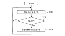
- FIG. 4 is a flowchart showing processing by the upper control apparatus of FIG.
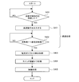
- FIG. 5 is a flowchart showing part of processing by the control unit of FIG.
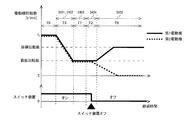
- FIG. 6 is a time chart showing a part of processing by the control unit of FIG.
- the host control device 46 receives the number of revolutions f from the control unit 1 (step S101). Next, the host control device 46 compares the rotation speed f received from the control unit 1 with the reference rotation speed X1 and determines whether the rotation speed f is less than or equal to the reference rotation speed X1 (step S102).
- step S102 If the number of revolutions f is less than or equal to the reference number of revolutions X1 (step S102 / YES), the host control device 46 transmits a switch instruction of the number to the control unit 1 (step S103). On the other hand, if the number of revolutions f is larger than the reference number of revolutions X1 (step S102 / NO), the host control device 46 returns to the process of step S101.
- control unit 1 stands by until receiving a number switching instruction from the host control device 46 (step S201 / NO). That is, when the control unit 1 does not receive the number switching instruction from the host control device 46, the control unit 1 does not perform the process related to the number switching of the motor.
- control unit 1 When the control unit 1 receives a number switching instruction from the host control device 46 (step S201 / YES), the control unit 1 outputs an element off signal to each of the switching elements 4a to 4f. Thus, the switching elements 4a to 4f are turned off (step S202). Next, the control unit 1 outputs a contact point off signal to the switch device 7. As a result, the switch device 7 is turned off (step S203).
- control unit 1 shorts the lines of the first electric motor 21 to brake the rotation of the first electric motor 21. At that time, the control unit 1 starts counting (step S204). Next, the control unit 1 stands by until the count time becomes equal to or greater than the brake processing time (step S205 / NO). Then, when the count time becomes equal to or longer than the brake processing time, the control unit 1 ends the brake processing, and sends the three-phase voltage command value Vuvw_ref necessary for driving the first electric motor 21 forward to the power converter 3. Output. Thereby, the first electric motor 21 starts driving (step S206).
- FIG. 6 shows a flow of operation from the transmission of the unit switching command to the execution of the start processing by the first electric motor 21 when two units are simultaneously operated.
- the abscissa represents the elapsed time
- the first stage of the ordinate represents the rotational speed of the motor
- the second stage of the ordinate represents the driving state of the switch device 7. That is, in the first stage, the rotational speed of the first electric motor 21 is represented by a solid line, and the rotational speed of the second electric motor 22 is represented by a broken line.
- the second stage shows the on / off state of the switch device 7.
- the period T1 corresponds to the all switching element off process in step S202 in FIG. 5, and the period T2 corresponds to the switch device off process in step S203 in FIG. Further, a period T3 corresponds to the braking process of steps S204 and S205 of FIG. 5, and a period T4 corresponds to the activation process of step S206 of FIG.
- the operation of the first motor 21 and the second motor 22 and the operation of the switch device 7 will be described for each period corresponding to each process of FIG. 5 with reference to FIG.
- switch device off process (T2) In the period T2, the first motor 21 and the second motor 22 are in the free run state.
- the switch device 7 When the contact point off signal is output from the control unit 1 to the switch device 7, the switch device 7 is turned off, and the second motor 22 is electrically disconnected from the power conversion device 3. At this time, the current flowing through the switch device 7 is interrupted by the all switching element off process.
- the motor control device 10 changes the power conversion device 3 to the second motor 22 by turning off the six switching elements 4 a to 4 f before the switch device 7 is turned off. It is possible to interrupt the flowing current. Then, the current flowing from the power conversion device 3 to the switch device 7 is cut off, so the amount of current change when the switch device 7 is turned off becomes small, and the surge voltage proportional to the current change when the switch device 7 is turned off is also It becomes smaller.
- the switch device 7 is turned off. Therefore, according to the motor control device 10, when the switch device 7 is turned off, the current flowing through the switch device 7 can be reduced, so that the surge voltage proportional to the amount of change in current can be suppressed low. Therefore, while being able to suppress the failure
- the motor control device 10 turns off the switch device 7 and electrically disconnects the second motor 22 from the power conversion device 3, and then performs the brake processing. Therefore, it is possible to reduce the current generated at the time of braking as compared with the case where the two motors are simultaneously braked.
- the number of rotations f 1 of the first electric motor 21 can be swiftly 0 [r / min] in a shorter time than in the case of simultaneously applying braking to two electric motors. Can be. Therefore, the time until the restart can be shortened, and the decrease in heat exchange capacity of the heat exchanger unit 30 due to the first fan 31 not rotating can be alleviated.
- the control unit 1 may use a graph or the like in which the initial rotation speed f 0 is associated with the brake processing time.
- the motor control device 10 executes the all switching element off process, the switch device off process, and the brake process in this order. Therefore, since the second electric motor 22 is not braked and can maintain the free run state, the reduction of the heat exchange capacity of the heat exchanger unit 30 can be alleviated.
- the motor control device 10 of the first embodiment since the surge voltage applied to the switch device 7 can be suppressed to a low level, the damage and the life reduction of the switch device 7 can be suppressed. As a result, the reliability of the motor control device 10 can be improved. In addition, while suppressing the influence on the heat exchange capacity of the heat exchanger unit 30, it is possible to carry out the switching process of the number of operated motors.
- the reference rotation speed X1 is set to the rotation speed f when the suction air volume in the two-unit simultaneous operation becomes equal to the maximum value of the suction air volume in the one-unit operation. That is, since the reference rotation speed X1 is based on the air volume that can be sucked by one fan, the suction air volume can be maintained at the time of switching to one-unit operation, and heat exchange of the heat exchanger unit 30 is performed. Ability to keep.
- control unit 1 of the second embodiment receives the number switching instruction from the host control device 46, the control unit 1 executes the all switching element off process, the switch apparatus off process, the estimation process, and the activation process in this order. . That is, the control unit 1 performs estimation processing instead of the brake processing in the first embodiment.
- control unit 1 estimates the number of rotations f 1 of the first electric motor 21 in the free run state and the position of the rotor of the first electric motor 21, and based on each estimated value. Execute startup processing.
- the position of the rotor corresponds to the phase of the rotor.
- storage unit 1a of control unit 1 includes characteristic information indicating characteristics such as inertia of first motor 21, second motor 22, first fan 31, and second fan 32, which will be described later.
- the rotation speed reduction information is stored.
- the control unit 1 estimates the number of revolutions f 1 of the first motor 21 and estimates the magnetic pole position of the rotor of the first motor 21 as an initial number of revolutions f 0 , initial position information, and an elapsed time after turning off. It carries out using characteristic information.
- the initial number of revolutions f 0 is the number of revolutions f immediately before shifting to all switching element off processing.
- the initial position information is information of the magnetic pole position of the rotor of the first electric motor 21 immediately before shifting to the all switching element off process. That is, the initial position information is information on the magnetic pole position of the rotor of the setting motor immediately before all the switching elements 4a to 4f are turned off.
- the post-off elapsed time is an elapsed time after all the plurality of switching elements 4a to 4f are turned off, and the control unit 1 counts time.
- the characteristic information is information indicating characteristics such as inertia of the first motor 21 and the first fan 31.
- the rotation speed f and the rotation speed f 1 are equal to each other immediately before shifting to the all switching element off processing.
- the free run rotational speed is the rotational speed of the motor in the free run state
- the rotational speed f 1 of the first electric motor 21 after the switching elements 4a to 4f are turned off.
- the rotation speed reduction information is information in which the elapsed time after off is associated with the estimated rotation speed which is an estimated value of the free run rotation speed, and the estimated rotation speed is configured to decrease when the elapsed time after off increases.
- the rotation speed reduction information it is possible to adopt a reduction information table in which the elapsed time after OFF and the estimated rotation speed are associated, or a graph in which the elapsed time after OFF and the estimated rotation speed are associated.
- control unit 1 can be estimated by using the initial rotational speed f 0 and off after time, the rotational speed f 1 of the first electric motor 21 that is a free-run state. That is, the control unit 1 can obtain the estimated rotation speed by illuminating the rotation time decrease information corresponding to the initial rotation speed f 0 with the elapsed time after the turn-off.
- the magnetic pole position of the rotor can be calculated by time integration of the rotational angular velocity of the rotor. That is, the control unit 1 is in the free run state based on the information indicating the relationship between the post-off elapsed time and the free-run rotational speed previously confirmed in the experiment, the post-off elapsed time, and the initial position information
- the magnetic pole position of the rotor of the first motor 21 can be estimated. That is, the control unit 1 obtains the estimated value of the magnetic pole position of the rotor of the first motor 21 in the free run state as the estimated position information.
- the control unit 1 uses the estimated rotation number obtained from the rotation number decrease information as the information indicating the relationship between the post-off elapsed time and the free run rotation number.
- the control unit 1 generates a three-phase voltage command value Vuvw_ref by using the estimated rotation number and estimated position information estimated in the immediately preceding estimation process as the start-up process, and outputs the three-phase voltage command value Vuvw_ref to the power conversion device 3.
- the power conversion device 3 outputs, to the first electric motor 21, a voltage having a magnitude, frequency, and phase synchronized with the rotor.
- the first electric motor 21 follows the target rotational speed after the stator and the rotor are synchronized.
- control unit 1 obtains the estimated rotation speed by referring to the rotation speed decrease information for the elapsed time after the turn-off. Further, the control unit 1 obtains the estimated position information using the calculated estimated number of rotations, the initial position information, and the elapsed time after the OFF. Then, the control unit 1 synchronizes the magnetic pole positions of the rotor and the stator of the setting motor using the estimated position information thus obtained, and restarts the setting motor.
- FIG. 7 is a flowchart showing a part of processing by the control unit of the motor control device according to Embodiment 2 of the present invention.
- FIG. 8 is a time chart showing a part of processing by the control unit of the motor control device according to Embodiment 2 of the present invention.
- control unit 1 executes the processing of steps S201 to S203 as in the case of FIG.
- control unit 1 the elapsed time after off in timing, by illuminating the rotational speed reducing information corresponding to the initial rotational speed f 0, determine an estimated rotational speed of the first electric motor 21 (step S301). Then, using the relationship between the post-off elapsed time and the free-run rotational speed, the post-off elapsed time, and the initial position information, the control unit 1 estimates the estimated position of the magnetic pole position of the rotor of the first electric motor 21. Information is obtained (step S302).
- control unit 1 by using the estimated rotational speed and estimated position information, to follow the stator and the rotor of the first electric motor 21 is synchronized, and the rotational speed f 1 of the first electric motor 21 to the target rotational speed Three-phase voltage command value Vuvw_ref is generated. Then, the control unit 1 outputs the generated three-phase voltage command value Vuvw_ref to the power conversion device 3 (step S303).
- FIG. 8 shows a flow of operation from the transmission of the unit switching command to the execution of the start processing by the first electric motor 21 when two units are simultaneously operated.
- the basic configuration of the time chart of FIG. 8 is the same as that of the time chart of FIG.
- a period T1 corresponds to the all switching element off process in step S202 in FIG. 7, and a period T2 corresponds to the switch device off process in step S203 in FIG.
- a period T5 corresponds to the estimation process of steps S301 and S302 of FIG. 7, and a period T4 corresponds to the activation process of step S303 of FIG.
- the operations of the first motor 21 and the second motor 22 and the operation of the switch device 7 will be described with reference to FIG. 8, centering on the estimation process.
- the first motor 21 and the second motor 22 enter a free run state, and their rotational speeds gradually decrease.
- the switch device 7 is turned off in the period T2
- the period T5 the estimated rotation number and the estimated position information are obtained.
- the first motor 21 and the second motor 22 are in the free run state.
- the first motor 21 is restarted using the estimated rotational speed and the estimated position information obtained by the estimation process of the period T5. Thereafter, the first electric motor 21 accelerates to the target rotational speed.
- the rotation speed period in the middle of f 1 is decreased T5 and the period T4 of the first electric motor 21, for carrying out the estimation process and startup process, the rotational speed f 1 of the first electric motor 21 It does not decrease to 0 [r / min].
- the rotational speed f 2 is 0 [r / min in the free running state. ] To decrease.
- the motor control device 10 performs the rotation speed estimation process and the start process while the rotation speed f 1 of the first motor 21 is decreasing, so that the first fan in the free running state is performed.
- the first electric motor 21 can be restarted without stopping the rotation of 31. Therefore, the reduction in heat exchange capacity of the heat exchanger unit 30 can be further mitigated.
- the motor control device 10 since the motor control device 10 does not perform the braking process, the time required for the braking process becomes unnecessary. In addition, since the motor control device 10 does not reduce the number of revolutions f 1 of the first motor 21 to 0 [r / min], the operation of accelerating the first motor 21 from 0 [r / min] becomes unnecessary. . Therefore, the time required for the switching process of the number of operating motors can be shortened.
- control unit 1 receives the number switching instruction from the host control device 46, the control unit 1 executes the deceleration processing, the current zero cross detection processing, the switch device off processing, and the acceleration processing in this order. That is, the control unit 1 performs deceleration processing and current zero cross detection processing instead of the brake processing in the first embodiment.
- the deceleration processing is processing in which the control unit 1 decelerates the first electric motor 21 and the second electric motor 22 to the minimum operable rotational speed. That is, the control unit 1 outputs the three-phase voltage command value Vuvw_ref for operating the first motor 21 and the second motor 22 at the lowest operable rotational speed to the power conversion device 3 as the deceleration command.
- the current flowing through the switch device 7 is an alternating current in which the positive and negative of the current value, which is its value, change periodically. That is, the current zero cross detection process is a process in which the control unit 1 detects the timing at which the current value switches from positive to negative or from negative to positive, that is, the zero cross.
- the current of each phase detected using the shunt resistors 6u to 6w is in phase with the current flowing to each phase of the switch device 7, respectively. That is, the zero cross of the three-phase current Iuvw detected by the controller 1 using the shunt resistors 6u to 6w matches the zero cross of the current flowing through the switch device 7. Therefore, the control unit 1 of the third embodiment detects the current zero cross which is the zero cross of the three-phase current Iuvw as the current zero cross detection process.
- the control unit 1 outputs a contact point off signal to the switch device 7 so that the switch device 7 can be turned off at the current zero cross as the switch device off processing.
- a time lag occurs between when the control unit 1 detects the current zero cross and the switch device 7 is turned off. This is because there is a series of operations in which the control unit 1 outputs an off signal to the switch device 7 and the switch device 7 is turned off after detecting the current zero cross. That is, the control unit 1 can not immediately turn off the switch device 7 when detecting the current zero cross.
- the control unit 1 in order to more precisely turn off the switch device 7 at the current zero cross, applies a predetermined offset to the timing of the current zero cross to make the switch device 7 contact off signal. Is supposed to be output.
- the control unit 1 calculates a predetermined offset based on the frequency of the current and the delay time until the switch device 7 is turned off.
- contact portions are connected to two phases of the U2 phase and the W2 phase. That is, the first contact portion 7x is connected to the U2 phase, and the second contact portion 7y is connected to the W2 phase.
- the switching instruction signal SW transmitted by the control unit 1 to the switch device 7 is not divided into each phase, and a plurality of phases are collectively managed by the same instruction. Therefore, at the timing when the U2-phase current and the W2-phase current cross the zero, the contact OFF signal as the switching instruction signal SW is transmitted independently to each of the first contact portion 7x and the second contact portion 7y. I can not do it.
- the control unit 1 alternately switches the trigger for outputting the contact point off signal at the timing at which the U2 phase current crosses zero and the timing at which the W2 phase current crosses zero. ing. That is, the control unit 1 alternately uses the zero cross of the current flowing in the U phase of the power conversion device 3 and the zero cross of the current flowing in the W phase of the power conversion device 3 as the zero cross of the three phase current Iuvw There is. More specifically, when the switch device 7 is turned off at the timing when the current flowing in the U2 phase crosses zero, the control unit 1 switches the switch device at the timing when the current flowing in the W2 phase crosses zero at the time of the next switch device off processing. Turn 7 off.
- the phase which detects a zero crossing may be replaced, for example, every fixed number of times instead of being replaced every time the switch device is turned off. That is, the control unit 1 may periodically switch the timing of outputting the contact point off signal between the timing at which the U2 phase current crosses zero and the timing at which the W2 phase current crosses zero. In this way, the burden can be distributed between the first contact portion 7 x and the second contact portion 7 y in the switch device 7.
- the acceleration process is a process of accelerating the first electric motor 21 operating at the lowest operable rotational speed to a target rotational speed. That is, the control unit 1, as an acceleration process to generate a three-phase voltage values Vuvw_ref made to follow the rotational speed f 1 of the first electric motor 21 to the target speed, and outputs to the power converter 3.
- FIG. 9 is a flowchart showing a part of processing by the control unit of the motor control device according to Embodiment 3 of the present invention.
- FIG. 10 is a time chart showing a part of processing by the control unit of the motor control device according to Embodiment 3 of the present invention.
- Control unit 1 decelerates power conversion device 3 so that first motor 21 and second motor 22 can be operated at the minimum number of rotations that can be operated, when the number switching instruction is received from host controller 46 (step S201 / YES).
- the command is output (step S401).
- the control unit 1 stands by until the number of revolutions f decreases to the minimum number of revolutions (step S402 / NO).
- Control part 1 will detect the current zero crossing in three-phase current Iuvw, if number of rotations f falls to the minimum number of rotations (Step S402 / YES) (Step S403). Then, the control unit 1 applies a predetermined offset to the current zero crossing timing, and outputs a contact point off signal to the switch device 7 (step S404). Then, the control unit 1, the rotation speed f 1 of the first electric motor 21 generates the three-phase voltage values Vuvw_ref such that the target rotation speed, and outputs to the power converter 3 (step S405).
- FIG. 10 shows a flow of operation from the transmission of the unit switching command to the execution of the start processing by the first electric motor 21 when two units are simultaneously operated.
- the basic configuration of the time chart of FIG. 10 is the same as that of the time charts of FIGS.
- a period T6 corresponds to the deceleration processing in steps S401 and S402 in FIG. 9, and a period T7 corresponds to the current zero cross detection processing in step S403 in FIG.
- a period T2 corresponds to the switch device off process in step S404 in FIG. 9, and a period T8 corresponds to the acceleration process in step S405 in FIG.
- the operation of the first motor 21 and the second motor 22 and the operation of the switch device 7 will be described with reference to FIG.
- the control unit 1 that has received the number switching instruction from the host controller 46 controls the three-phase voltage of the power conversion device 3 so that the first electric motor 21 and the second electric motor 22 can operate at the lowest rotation speed.
- the command value Vuvw_ref is output. Therefore, the first electric motor 21 and the second electric motor 22 decelerate to the minimum number of revolutions at the decelerating speed determined as the control constant.
- the current zero cross detection process in period T7 is performed, and then transition is made to period T2, and the switch device 7 is transitioned to the off state.
- the switch device 7 is turned off, the second motor 22 is electrically disconnected from the power conversion device 3 and enters a free run state. Therefore, it decelerated as shown in FIG. 10, the rotational speed f 2 of the second electric motor 22 is reduced to 0 [r / min].
- the first electric motor 21 remains electrically connected to the power conversion device 3, and the operation state up to that point is continued. That is, the first electric motor 21 continues the operation at the lowest rotational speed. And if it transfers to period T8, the 1st electric motor 21 will accelerate to target number of rotations.
- the timing at which the switch device 7 is turned off is such that the phase used for the determination of the zero crossing is alternated as the next time adopting the current zero crossing of the U2 phase adopts the current zero crossing of the W2 phase. It has become. That is, the control unit 1 switches the phase of the current used as the condition for turning off the switch device 7 every time the switch device 7 is turned off. Therefore, stress can be prevented from continuing to be applied to only the contact portion of the switch device 7 connected to one phase, so that the failure of the switch device 7 can be suppressed and the life can be extended.
- the surge voltage applied to the switch device 7 can be suppressed to a low level as in the first embodiment, and the damage and the life reduction of the switch device 7 can be suppressed. . Therefore, the highly reliable motor control device 10 can be provided.
- the highly reliable motor control device 10 can be provided.
- the motor control device 10 When the motor control device 10 turns off the switch device 7, the motor control device 10 restarts the driving of the first motor 21 without stopping the driving of the first motor 21, and therefore does not stop the rotation of the first fan 31. Therefore, as in the second embodiment, the decrease in heat exchange capacity of the heat exchanger unit 30 can be mitigated.
- the time required for the braking process is unnecessary, and the acceleration from 0 [r / min] of the first motor 21 is unnecessary, so the process for switching the number of operating motors is required. Time can be shortened.
- the process of synchronizing the magnetic poles of the rotor and the magnetic poles of the stator in the free run state with the magnetic poles of the stator is unnecessary, the control content can be simplified.
- the configurations of the air conditioner and the motor control device according to the fourth embodiment are the same as those shown in FIG. 1. Therefore, the same components as those in the first to third embodiments are denoted by the same reference numerals and the description thereof is omitted.
- the fourth embodiment is characterized in that the control unit 1 performs a current peak detection process instead of the current zero cross detection process in the third embodiment described above.
- the other control configuration is the same as that of the third embodiment.
- FIG. 11 is a graph showing waveforms of three-phase alternating current flowing in the motor of the air conditioning apparatus according to Embodiment 4 of the present invention.
- FIG. 11 illustrates changes over time of the U2-phase current, the V2-phase current, and the W2-phase current.
- the U2-phase current is indicated by a solid line
- the V2-phase current is indicated by a broken line
- the W2-phase current is indicated by an alternate long and short dash line.
- the current of the V2 phase is the maximum value or the minimum value at the time when the point A is located. Therefore, in the fourth embodiment, a configuration is employed in which the point indicated by point A in FIG. 11 is detected by detecting the peak of the V2 phase current using the above-mentioned current-related relationships of each phase. Have taken
- control unit 1 is configured to detect a peak or a valley of a sine wave of a V2-phase current not provided with the contact portion, that is, a current peak as the current peak detection process. Then, the control unit 1 outputs a contact point off signal to the switch device 7 so that the switch device 7 can be turned off by the current peak of the V2 phase detected in the current peak detection process as the switch device off process.
- a time lag occurs from when the control unit 1 detects the current peak of the V2 phase until the switch device 7 is turned off. Therefore, in the fourth embodiment, in order to turn off the switch device 7 more strictly at the current peak of the V2 phase, the control unit 1 applies a predetermined offset to the timing of the current peak of the V2 phase, A contact off signal is output to the switch device 7. The control unit 1 calculates a predetermined offset based on the frequency of the current and the delay time until the switch device 7 is turned off.
- FIG. 12 is a flowchart showing a part of processing by the control unit of the motor control device according to Embodiment 4 of the present invention.
- the operation in the case of switching the operating state of the motor from two simultaneous driving to one single driving will be described.
- the same processes as in FIG. 9 will be assigned the same reference numerals and descriptions thereof will be omitted.
- the time chart in the fourth embodiment is the same as that in FIG. 10 in the third embodiment, and is thus omitted.
- the operation of the host control device 46 is the same as that in the case of FIG.
- the control unit 1 executes the processes of steps S201, S401, and S402 in the same manner as in the case of FIG. Then, when the rotation speed f is reduced to the minimum rotation speed (step S402 / YES), the control unit 1 detects the current peak of the V2 phase in which the contact portion is not provided (step S501). Then, the control unit 1 applies a predetermined offset to the timing of the current peak of the V2 phase, and outputs a contact point off signal to the switch device 7 (step S502). Next, the control unit 1 executes the process of step S405 as in the case of FIG.
- the motor control device 10 of the fourth embodiment reduces the rotational speed f of the first motor 21 and the second motor 22 to the minimum rotational speed by deceleration processing. Furthermore, the motor control device 10 causes the switch device 7 to be turned off at a timing at which the magnitudes of the U2 phase current and the W2 phase current are not uneven and become as small as possible. Therefore, the surge voltage applied to the switch device 7 can be suppressed low.
- the current value of the U2 phase and the current value of the W2 phase become equal and relatively small. Therefore, the stress applied to the U2-phase first contact portion 7x and the W2-phase second contact portion 7y can be reduced, and the load can be dispersed between the first contact portion 7x and the second contact portion 7y. Therefore, the failure of the switch device 7 can be suppressed and the life can be extended.
- the other effects and advantages are the same as in the third embodiment.
- Embodiment 5 The air conditioning apparatus according to the fifth embodiment differs from the first to fourth embodiments in the configuration of the motor control device. Also, the control content by the host control device is different from the flowchart of FIG. 4. However, since the configuration of the air conditioner is the same as that shown in FIG. 1, the same components as those in the first to fourth embodiments described above will be assigned the same reference numerals and descriptions thereof will be omitted.
- FIG. 13 is a control block diagram illustrating the configuration of a motor control device according to a fifth embodiment of the present invention.
- the motor control device 110 of the fifth embodiment is additionally provided with a current detection device 13.
- the current detection device 13 is, for example, a current sensor, and detects a current flowing through the three-phase power line 8 connecting the first motor 21 and the power conversion device 3.
- the motor control device 110 has a control unit 101 instead of the control unit 1.
- the control unit 101 reduces the number of rotations of the two motors being operated below the current number of rotations. And the switch device 7 is turned off.
- the current difference value Id which is the difference between the current Iuvw1 flowing to the first motor 21 and the current Iuvw2 flowing to the second motor 22.
- the reference current value X2 Judge from what has become. Then, when the current difference value Id becomes equal to or greater than the reference current value X2, the parallel operation of the first motor 21 and the second motor 22 is switched to the sole operation of only the first motor 21.
- the current Iuvw1 flowing through the first motor 21 is detected by the current detection device 13.
- the currents detected by the shunt resistors 6u to 6w shown in FIG. 3 are the sum of the current Iuvw1 flowing to the first motor 21 and the current Iuvw2 flowing to the second motor 22. Therefore, the current Iuvw2 flowing through the second motor 22 can be obtained by subtracting the current Iuvw1 detected by the current detection device 13 from the three-phase current Iuvw detected by the shunt resistors 6u to 6w.
- control unit 101 acquires the number of revolutions f of the first electric motor 21 and the second electric motor 22, and outputs the rotational speed f to the upper control device 46.
- the control unit 101 acquires the current Iuvw1 flowing from the current detection device 13 to the first electric motor 21 over time.
- the control unit 101 also obtains the current Iuvw2 flowing through the second motor 22 by subtracting the current Iuvw1 from the three-phase current Iuvw. Then, the control unit 101 obtains a current difference value Id which is a difference between the current Iuvw1 and the current Iuvw2, and outputs the obtained current difference value Id to the upper control device 46.
- the other configuration of the control unit 101 is the same as that of the control unit 1 of the first to fourth embodiments.
- the upper control device 46 compares the rotational speed f received from the control unit 101 with the reference rotational speed X1 as in the above embodiments, and determines the control unit 1 when the rotational speed f is less than or equal to the reference rotational speed X1. In response to this, it sends a unit switching command. Further, the host control device 46 according to the fifth embodiment compares the current difference value Id output from the control unit 101 with the reference current value X2, and also when the current difference value Id is equal to or greater than the reference current value X2. And sends a switch command to the control unit 1.
- FIG. 14 is a flowchart showing processing by the upper control apparatus of the air conditioning apparatus according to Embodiment 5 of the present invention. Referring to FIG. 14, a control procedure performed by the host control device 46 in connection with the switching of the number of motors will be described. In FIG. 14, the determination condition at the time of transmitting the unit switching instruction is different from that in FIG. 4. The same processes as in FIG. 4 will be assigned the same reference numerals and descriptions thereof will be omitted.
- the host control device 46 receives the number of revolutions f and the current difference value Id from the control unit 1 (step S601). Next, the host control device 46 determines whether the number of revolutions f is equal to or less than the reference number of revolutions X1. Further, the host controller 46 compares the current difference value Id with the reference current value X2, and determines whether the current difference value Id is equal to or greater than the reference current value X2 (step S602).
- step S602 / YES If the host controller 46 satisfies the determination condition that the number of revolutions f is equal to or less than the reference number of revolutions X1 or the current difference value Id is equal to or more than the reference current value X2 (step S602 / YES). The command is transmitted (step S103). On the other hand, if the above-described determination condition is not satisfied (step S602 / NO), the host control device 46 returns to the process of step S601.
- the comparison and determination between the rotational speed f and the reference rotational number X1 and the comparison and determination between the current difference value Id and the reference current value X2 are performed at the same timing.
- the control device 46 may perform each comparison determination at different timings. Therefore, the timing of receiving the rotation speed f from the control unit 1 and the timing of receiving the current difference value Id from the control unit 1 may be different.
- control part 101 may output the current Iuvw1 and the current Iuvw2, or the current Iuvw1 and the current Iuvw1 to the higher-level control device 46.
- the host controller 46 obtains the current difference value Id and then compares it with the reference current value X2.
- the motor control device 110 can suppress the surge voltage applied to the switch device 7 to a low level, and can suppress the damage and the life reduction of the switch device 7. .
- the reliability of the motor control device 110 can be improved.
- the number switching instruction is transmitted from the host control device 46 even when the current difference value Id which is the difference between the current Iuvw1 and the current Iuvw2 is equal to or greater than the reference current value X2. Be done. Therefore, it is possible to switch from parallel operation of the first electric motor 21 and the second electric motor 22 to sole operation of only the first electric motor 21 before the current diverges due to the disturbance phenomenon and the operation continuation of the electric motor becomes difficult. Therefore, the abnormal stop of the 1st electric motor 21 and the 2nd electric motor 22 can be avoided, and rotation of the 1st fan 31 can be continued.
- control for suppressing the disturbance also exists, but it may be difficult to suppress the disturbance in the low rotation region of the motor, and such control for suppressing the disturbance is effective. May not work.
- abnormal stop of the motor can be avoided and operation can be continued even in the low rotation region of the motor.
- the configuration of the fifth embodiment can be applied to each of the first to fourth embodiments.
- the switch device 7 is provided only between the power conversion device 3 and the second motor 22 is illustrated in FIGS. 1 and 13, the present invention is not limited thereto. It may be provided between the branch of the power line 8 and the three-phase power line 9 and the first electric motor 21. That is, the switch device 7 is provided at least between the power conversion device 3 and the motor except one.
- the control units 1 and 101 may make the operating time of the first electric motor 21 equal to the operating time of the second electric motor 22.
- the structure in which two motors were connected to the motor control apparatus 10 or 110 was illustrated in FIG.1, FIG.2, and FIG.13, three units are not limited to this but the motor control apparatus 10 or 110.
- the above electric motors may be connected.
- the control units 1 and 101 switch from one in which two or more motors are in operation to one in which only the setting motor is operated, the rotational speeds of the two or more motors being operated are Lower than the number of revolutions of the switch, and then the switch device is turned off.
- the switch device 7 may be provided between the power conversion device 3 and the motor excluding one, or may be provided in association with each of all the motors. That is, the switch device 7 may be provided between at least the power conversion device 3 and the motor excluding one.
- the control units 1 and 101 When the switch device 7 is provided in association with each of all the motors, the control units 1 and 101 periodically set, for example, one motor so as to equalize the operating time of all the motors. Change it. That is, the control units 1 and 101 may appropriately change the setting motor based on the load balance of all the motors.
- the reference rotational speed X1 is equal to the maximum value of the suction air volume when only one motor is operating, with the suction air volumes by the plurality of fans when two or more motors are operating. The number of revolutions of the motor is set.
- control unit 1 of the third and fourth embodiments performs the zero-crossing of the three-phase current flowing in the electric motors.
- the switch device 7 is turned off by outputting an off signal to the switch device 7.
- the example which provided the motor control apparatus 10 or 110 in the outdoor unit 40 was shown in said each embodiment, it is not limited to this.
- the load side motor control device 54 may have the same function as the motor control device 10 or 110.
- the motor which drives a fan was illustrated as an electric motor in each said embodiment, the motor in not only this but the embodiment may be a compressor motor etc. which drives a compressor. .
- the upper control device 46 exemplifies the case where the determination of whether or not the number of revolutions f is equal to or less than the reference number of revolutions X1.
- the control units 1 and 101 may perform the determination of whether or not X1 or less.
- the reference rotational speed X1 may be stored in the storage unit 1a. Then, when the rotational speed f of two or more electric motors becomes equal to or less than the reference rotational speed X1, the control units 1 and 101 may switch to one-operation of the setting electric motor.
- the present invention is not limited thereto.
- the control unit 101 may determine whether or not the reference current value X2 or more.
- the reference current value X2 may be stored in the storage unit 1a. Then, when the current difference value Id becomes equal to or greater than the reference current value X2, the control unit 1 may switch to one-unit operation of the setting motor.
- the host control device 46 or the control units 1 and 101 may control to switch to one set motor operation when the state in which the rotation speed f is less than or equal to the reference rotation speed X1 continues for a fixed time.
- the host control device 46 or the control unit 101 may perform control to switch to one set motor operation when the state in which the current difference value Id is the reference current value X2 or more continues for a predetermined time.
- the contact part of the switch apparatus 7 was connected to the U-phase and W phase of the power converter device 3 was illustrated, not only this but the contact part of the switch apparatus 7 is
- the power converter 3 may be connected to any two of the three phases. That is, the control unit 1 according to the third embodiment causes the zero cross of the current flowing in one of the three phases of the power conversion device 3 as the zero cross of the three phase current Iuvw and the three phases of the power conversion device 3. The zero-crossing of the current flowing to one other phase is periodically replaced and used. Furthermore, when the control unit 1 of the fourth embodiment detects the peak of the current flowing in the remaining one phase to which each contact portion of the three phases of the power conversion device 3 is not connected, the switch device 7 is used. Output an off signal.
- the configuration of the air conditioning apparatus 100 is not limited to the configuration shown in FIG. 1 in which the outdoor unit and the indoor unit are connected by refrigerant piping, and the air conditioning apparatus 100 includes an outdoor unit such as a chiller and an indoor unit. It may be a combination. Furthermore, even if some of the embodiments are excluded, the above effects may be obtained. In addition, a part of each configuration of each embodiment may be incorporated into another embodiment to configure the motor control device.
Landscapes
- Engineering & Computer Science (AREA)
- Power Engineering (AREA)
- Control Of Multiple Motors (AREA)
Abstract
複数台の電動機に三相電圧を供給する電力変換装置と、少なくとも、電力変換装置と1台を除く電動機との間を電気的に接続し又は切断するスイッチ装置と、電力変換装置及びスイッチ装置の動作を制御する制御部と、を有する電動機制御装置。また、電動機制御装置を備えた熱交換器ユニット。制御部は、2台以上の電動機が運転している状態から、設定された1台の電動機である設定電動機だけが運転する1台運転に切り替える際、運転している2台以上の電動機の回転数を低下させてからスイッチ装置をオフ状態にするものである。
Description
本発明は、インバータからなる電力変換装置を用いて電動機の回転を制御する電動機制御装置及び熱交換器ユニットに関する。
従来から、空気調和装置は、圧縮機、熱源側熱交換器、減圧装置、及び負荷側熱交換器などが冷媒配管で接続され、封入された冷媒が循環する冷媒回路を有している。例えば、圧縮機及び熱源側熱交換器は室外機に設けられ、負荷側熱交換器は室内機に設けられる。空気調和装置は、冷媒回路内で冷媒を循環させることにより、室内機が配置された室内の空調を行う。空気調和装置において、室外機及び室内機は、それぞれ、熱交換器を含む熱交換器ユニットとして機能する。
上記のような空気調和装置の室外機は、熱源側熱交換器に送風するファンと、ファンを駆動する電動機制御装置とを備えている。電動機制御装置は、ファンの動力源となる電動機を駆動し、ファンを回転させることにより、熱源側熱交換器での冷媒と外気との間の熱交換を行う。電動機制御装置は、熱交換能力を制御する場合、ファンの回転数を制御し、ファンによって吸い込まれる風量を調整する。
空気調和装置には、吸い込む風量を大きくするため、複数台のファンが搭載された室外機を有するものもある。こうした室外機において、1台のファンに対し1台の電力変換装置を設ける構成を採ると、複数台のファンが搭載された室外機には、複数台のインバータが必要となる。また、1台の電力変換装置によって複数台の電動機を駆動する技術も知られている(例えば、特許文献1参照)。特許文献1の電動機制御装置では、1台の電力変換装置に、スイッチ装置を介して、3台の電動機が並列に接続されている。
複数台のファンが搭載された熱交換器ユニットにおいて、吸い込む風量を制御する場合、ファンの運転台数を切り替えることがある。例えば、熱交換器ユニットは、吸い込む風量を小さくする場合に、ファンの運転台数を減少させる。また、熱交換器ユニットは、複数台の電動機を低回転領域で運転させると、制御が不安定になる。そのため、熱交換器ユニットは、低回転領域では、複数台の電動機が運転しないよう、1台の電動機だけが運転する1台運転に切り替える。
しかしながら、特許文献1の構成において、複数台の電動機が運転している状態から1台運転に切り替えるために、スイッチ装置をオフ状態にすると、スイッチ装置にサージ電圧が発生する。スイッチ装置にサージ電圧がかかると、スイッチ装置の破損及び寿命の低下に繋がるという課題がある。
本発明は、上記のような課題を解決するためになされたもので、スイッチ装置にかかるサージ電圧を抑制し、スイッチ装置の破損及び寿命低下を抑制する電動機制御装置及び熱交換器ユニットを提供することを目的とする。
本発明に係る電動機制御装置は、電力を変換して互いに並列に接続された複数台の電動機に三相電圧を供給する電力変換装置と、少なくとも、電力変換装置と1台を除く電動機との間をオンオフ動作によって電気的に接続し又は切断するスイッチ装置と、電力変換装置及びスイッチ装置の動作を制御する制御部と、を有し、制御部は、2台以上の電動機が運転している状態から、設定された1台の電動機である設定電動機だけが運転する1台運転に切り替える際、運転している2台以上の電動機の回転数を低下させてからスイッチ装置をオフ状態にするものである。
本発明に係る熱交換器ユニットは、複数台の電動機と、複数台の電動機のそれぞれに接続された複数のファンと、上記の電動機制御装置と、2台以上の電動機が運転している場合に、運転している電動機の各々の回転数が基準回転数まで低下したとき、電動機制御装置に台数切替指令を送信する上位制御装置と、を備え、基準回転数は、2台以上の電動機が運転しているときの複数のファンによる吸込風量が、1台の電動機だけが運転しているときの複数のファンによる吸込風量の最大値と等しくなるときの2台以上の電動機のそれぞれの回転数に設定され、制御部は、上位制御装置から台数切替指令が送信されたとき、運転している2台以上の電動機の回転数を低下させてからスイッチ装置をオフ状態にするものである。
本発明によれば、複数台の電動機の回転数を低下させ、スイッチ装置に流れる電流を小さくしてからスイッチ装置をオフ状態にするため、スイッチ装置にかかるサージ電圧を抑制し、スイッチ装置の破損及び寿命低下を抑制することができる。
実施の形態1.
図1は、本発明の実施の形態1に係る空気調和装置の構成を例示した概略図である。図1に示すように、空気調和装置100は、室外機40と室内機50とを有する。室外機40は、圧縮機41と、四方弁42と、熱源側熱交換器43と、熱源側絞り装置44と、アキュムレータ45と、を有する。室内機50は、負荷側熱交換器51を有する。すなわち、空気調和装置100は、圧縮機41、四方弁42、熱源側熱交換器43、熱源側絞り装置44、負荷側熱交換器51、及びアキュムレータ45が冷媒配管61を介して接続され、冷媒が循環する冷媒回路60を有している。
図1は、本発明の実施の形態1に係る空気調和装置の構成を例示した概略図である。図1に示すように、空気調和装置100は、室外機40と室内機50とを有する。室外機40は、圧縮機41と、四方弁42と、熱源側熱交換器43と、熱源側絞り装置44と、アキュムレータ45と、を有する。室内機50は、負荷側熱交換器51を有する。すなわち、空気調和装置100は、圧縮機41、四方弁42、熱源側熱交換器43、熱源側絞り装置44、負荷側熱交換器51、及びアキュムレータ45が冷媒配管61を介して接続され、冷媒が循環する冷媒回路60を有している。
また、室外機40には、上位制御装置46と、電動機制御装置10と、第1電動機21と、第2電動機22と、第1ファン31と、第2ファン32とが設けられている。室内機50には、負荷側ファン52と、ファンモータ52aと、負荷側上位制御装置53と、負荷側電動機制御装置54とが設けられている。
圧縮機41は、例えばインバータによって駆動される圧縮機モータ(図示せず)を有し、冷媒を吸入して圧縮する。四方弁42は、圧縮機41に接続されており、上位制御装置46により制御されて冷媒の流路を切り替える。四方弁42は、熱源側熱交換器43が凝縮器として機能し、負荷側熱交換器51が蒸発器として機能する冷房運転時において、図1の実線の流路となる。一方、四方弁42は、負荷側熱交換器51が凝縮器として機能し、熱源側熱交換器43が蒸発器として機能する暖房運転時において、図1の破線の流路となる。
熱源側熱交換器43は、例えばフィンアンドチューブ型熱交換器からなり、冷媒回路60を流れる冷媒と外気との間で熱交換させる。熱源側絞り装置44は、例えば電子膨張弁からなり、冷媒を減圧し膨張させる。アキュムレータ45は、過剰な冷媒を貯留し、圧縮機41への液冷媒の流入を抑制する。
電動機制御装置10は、第1電動機21及び第2電動機22のそれぞれの回転数と、電動機の運転台数とを制御することで、室外機40における熱交換能力を制御する。第1ファン31及び第2ファン32は、熱源側熱交換器43に付設されており、熱源側熱交換器43に送風する。第1ファン31は、第1電動機21に接続されており、第1電動機21を動力源として回転する。第2ファン32は、第2電動機22に接続されており、第2電動機22を動力源として回転する。
ここで、第1電動機21の回転数をf1とし、第2電動機22の回転数をf2とする。一般に、電動機の並列運転、つまり電動機の複数台同時運転のとき、各電動機の回転数は等しくなる。すなわち、通常の2台同時運転のとき、第1電動機21の回転数f1と第2電動機22の回転数f2とは等しくなる。そのため、本実施の形態1の各処理を行っていない通常の2台同時運転時の第1電動機21及び第2電動機22の回転数をfとする。
負荷側熱交換器51は、例えばフィンアンドチューブ型熱交換器からなり、冷媒回路60を流れる冷媒と室内の空気との間で熱交換させる。第1電動機21及び第2電動機22は、負荷側上位制御装置53に設けられたインバータ(図示せず)によって駆動される。負荷側ファン52は、ファンモータ52aを動力源として回転し、負荷側熱交換器51に空気を送風する。負荷側上位制御装置53は、負荷側電動機制御装置54を介して、負荷側ファン52の動作を制御する。負荷側電動機制御装置54は、ファンモータ52aの回転数を制御することで、室内機50における熱交換能力を制御する。
図2は、本発明の実施の形態1における電動機制御装置の構成を例示した制御ブロック図である。電動機制御装置10は、互いに並列に接続された複数台の電動機を駆動するものである。図2に示すように、電動機制御装置10は、制御部1と、直流電源2と、直流電圧を三相電圧に変換する電力変換装置3と、電力変換装置3と第2電動機22との間をオンオフ動作によって電気的に接続し又は切断するスイッチ装置7と、を有する。
スイッチ装置7は、例えばリレーであり、電力変換装置3の三相のうちの1つの相に接続された第1接点部7xと、電力変換装置3の三相のうちの他の1つの相に接続された第2接点部7yと、を有する。本実施の形態1において、第1接点部7xは、電力変換装置3の三相のうちのU相に接続され、三相電力線9のうちのU2相の電力線を電気的に接続し又は切断する。第2接点部7yは、電力変換装置3の三相のうちのW相に接続され、三相電力線9のうちのW2相の電力線を電気的に接続し又は切断する。
電力変換装置3は、例えばインバータであり、電力を変換して互いに並列に接続された複数台の電動機に三相電圧を供給する。本実施の形態1では、電動機制御装置10の制御対象となる第1電動機21及び第2電動機22が並列に接続されている。ここで、電動機制御装置10、第1電動機21、第2電動機22、第1ファン31、及び第2ファン32は、熱交換器ユニット30に含まれている。熱交換器ユニット30は、室外機40であってもよいし、室外機40の一部の構成であってもよい。
第1電動機21及び第2電動機22は、例えばブラシレスDCモータであり、電力変換装置3によって駆動される。第1電動機21には、負荷となる第1ファン31が取り付けられており、第2電動機22には、負荷となる第2ファン32が取り付けられている。第1電動機21は、三相電力線8を介して電力変換装置3と接続されている。ここで、本実施の形態1では、電力変換装置3と直接接続されている第1電動機21が、1台運転させる電動機に設定されている。つまり、第1電動機21は、本発明の「設定電動機」に相当する。
第2電動機22は、三相電力線8の途中から分岐した三相電力線9を介して電力変換装置3と接続されている。三相電力線9における三相電力線8との分岐と第2電動機22との間には、スイッチ装置7が設けられている。第1電動機21及び第2電動機22は、それぞれ、回転子(不図示)と、印加される三相電圧にしたがって回転子の周囲に回転磁界を発生させる固定子(不図示)と、を有する。
ここで、ブラシレスDCモータは、回転子の位置に応じて適切な位相及び周波数の三相交流電圧を固定子(不図示)に印加し、回転子の周囲に回転磁界を発生させ、回転磁界と回転子との吸引及び反発を利用して、回転子を所望の回転数で回転させる。その際、回転子の位置を検出する必要がある。回転子の位置を検出する方法としては、例えば、電動機に設置されたホールセンサによって検出する方法、又は周知の電動機に流れる三相電流から演算によって算出する方法を用いることができる。本実施の形態1では、電動機制御装置10が、後者の方法によって回転子の位置を推定する場合を例示する。
直流電源2は、例えば、電動機制御装置10の外部の単相電源又は三相電源から供給される交流電圧を直流電圧に変換して出力する整流回路である。電力変換装置3は、制御部1からの三相電圧指令値Vuvw_refに基づいて、第1電動機21及び第2電動機22を駆動する。すなわち、電力変換装置3は、制御部1から出力される三相電圧指令値Vuvw_refを、変調が行われていない基準信号であるキャリア波と比較し、PWM制御を実行する。
制御部1は、第1電動機21の回転数f1と、第2電動機22の回転数f2とを経時的に取得する。制御部1は、上位制御装置46から入力される回転数指令値ω_refと、検出した三相電流Iuvwに基づいて、周知のベクトル制御を実施し、電力変換装置3に三相電圧指令値Vuvw_refを出力する。また、制御部1は、スイッチ装置7に切替指示信号SWを出力する。切替指示信号SWは、例えば、スイッチ装置7に対して、オフ状態からオン状態への切り替え、又はオン状態からオフ状態への切り替えを指示するものである。
ここで、スイッチ装置7は、制御部1から切替指示信号SWを受け取ると、切替指示信号SWにしたがって、電力変換装置3と第1電動機21とを接続する三相電力線8に第2電動機22を接続したり、三相電力線8から第2電動機22を切り離したりする。すなわち、スイッチ装置7は、第1接点部7x及び第2接点部7yがオンであるオン状態のときに、第2電動機22を三相電力線8に接続し、第1接点部7x及び第2接点部7yがオフであるオフ状態のときに、第2電動機22を三相電力線8から切り離す。
また、第1ファン31及び第2ファン32は、第1電動機21及び第2電動機22のそれぞれに個別に接続されている。そして、スイッチ装置7がオフ状態にあるとき、第2電動機22は、電力変換装置3と電気的に切り離された状態となる。したがって、外風などの外乱トルクによって第2電動機22が回転しても、スイッチ装置7がオフ状態であれば、第2電動機22が第1電動機21と接続されていないため、第2電動機22の回転で発生する回生電流の第1電動機21に対する影響を遮断できる。すなわち、フリーラン状態の第2ファン32が、第1ファン31の負荷とならないようになっている。
制御部1は、上位制御装置46から台数切替指令を受信したとき、電力変換装置3を構成している6個のスイッチング素子4a~4fのそれぞれに素子オフ信号を出力する全スイッチング素子オフ処理を実行する。6個のスイッチング素子4a~4fは、それぞれ、素子オフ信号によりオフとなる。そして、制御部1は、6個のスイッチング素子4a~4fにオフの状態を維持させたまま、スイッチ装置7に接点オフ信号を出力するスイッチ装置オフ処理を実行する。スイッチ装置7は、接点オフ信号によりオフ状態となる。すなわち、第1接点部7x及び第2接点部7yは、それぞれ、接点オフ信号によりオフとなる。
さらに、制御部1は、スイッチ装置7をオフ状態にした後、後続する起動処理へ移るため、第1電動機21にブレーキをかけて第1電動機21の回転を止めるブレーキ処理を実行する。ここで、第1電動機21及び第2電動機22は、自身が回転することによって生じる電気エネルギーを素早く消費することで、素早く減速することができる。すなわち、制御部1は、第1電動機21の電気エネルギーを素早く消費するために、ブレーキ処理の一環として、第1電動機21の線間を短絡させる。第1電動機21の線間の短絡は、例えばスイッチング素子4a~4cを同時にオンすること、又はスイッチング素子4d~4fを同時にオンすることによって実現される。
また、制御部1は、ブレーキ処理に移行したとき、つまり第1電動機21の線間を短絡させたときからカウントを開始する。そして、制御部1は、カウントの積算値であるカウント時間が所定のブレーキ処理時間に到達したときに、起動処理を開始する。なお、制御部1は、起動処理を開始したとき、カウント時間をリセットする。
ここで、ブレーキ処理時間は、全スイッチング素子オフ処理へ移行する直前の回転数f、つまり複数のスイッチング素子4a~4fを全てオフにする直前の回転数fである初期回転数f0に応じて定まる。すなわち、本実施の形態1では、予め、初期回転数f0を想定した複数の回転数fごとに、全スイッチング素子オフ処理、スイッチ装置オフ処理、及びブレーキ処理を実施しておく。その際、ブレーキ処理の開始から第1電動機21の回転数f1が0[r/min]になるまでの時間データを、ブレーキ処理時間として取得する。そして、複数の回転数fと複数のブレーキ処理時間とを関連づけた処理時間テーブルを作成し、制御部1の記憶部1aに記憶させておく。処理時間テーブルでは、複数の回転数fと複数のブレーキ処理時間とが、回転数fが増加すると、ブレーキ処理時間が増加するように関連づけられている。よって、制御部1は、回転数fを処理時間テーブルに照らすことにより、ブレーキ処理時間を求めることができる。
制御部1は、起動処理として、第1電動機21が正転して駆動するのに必要な三相電圧指令値Vuvw_refを電力変換装置3に出力する。制御部1は、三相電圧指令値Vuvw_refを、上位制御装置46から入力される回転数指令値ω_refに基づいて生成する。すなわち、第1電動機21は、回転数指令値ω_refに応じて加速する。本実施の形態1の第1電動機21は、ブラシレスDCモータであるため、制御部1は、三相電圧指令値Vuvw_refを出力する前に、固定子と回転子の磁極位置をあわせる同期引き込み動作を実施する。
制御部1は、例えば、マイコンなどの演算装置と、こうした演算装置と協働して上記の各機能を実現させるソフトウェアとによって構成することができる。制御部1は、上記の各機能のうちの一部又は全部を実現する回路デバイスのようなハードウェアを含んで構成してもよい。
上位制御装置46は、第1電動機21及び第2電動機22のそれぞれの回転数を示す回転数指令値ω_refを制御部1に出力する。上位制御装置46は、種々の情報を記憶する記憶部46aを有している。記憶部46aには、電動機の台数を切り替える際の判定基準となる回転数であり、実機試験などにより予め設定された基準回転数X1が記憶されている。基準回転数X1は、第1電動機21と第2電動機22との2台同時運転から第1電動機21の1台運転に切り替える際の基準となる回転数である。
本実施の形態1において、基準回転数X1は、2台同時運転時の吸込風量が、1台運転時の吸込風量の最大値と等しくなるときの回転数fに設定される。吸込風量とは、第1ファン31及び第2ファン32によって熱交換器ユニット30へ吸い込まれる風量のことである。1台運転時の吸込風量の最大値とは、1台運転時において、電動機の回転数fを最大にしたとき、あるいは回転数fを切替回転数にしたときに、熱交換器ユニット30へ吸い込まれる風量のことである。切替回転数は、例えば、1台の電動機における回転数fの最大値の80[%]に設定され、適宜変更することができる。
上位制御装置46は、制御部1から第1電動機21及び第2電動機22の回転数fを取得するようになっている。また、上位制御装置46は、記憶部46aから基準回転数X1を読み出し、回転数fが基準回転数X1以下であるか否かを判定する。そして、上位制御装置46は、回転数fが基準回転数X1以下であれば、制御部1に台数切替指令を送信する。
上位制御装置46は、マイコンなどの演算装置と、こうした演算装置と協働して上記の各機能を実現させるソフトウェアとによって構成することができる。また、上位制御装置46は、上記の各機能のうちの一部又は全部を実現する回路デバイスのようなハードウェアを含んでいてもよい。
図3は、図2に示した電力変換装置の構成の一例を示す図である。図3に示すように、電力変換装置3は、6個のスイッチング素子4a~4fと、各スイッチング素子4a~4fに並列に設けられた逆流防止素子5a~5fと、三相電流Iuvwの演算用の電流検出部6と、を有する。電力変換装置3は、制御部1から受け取る三相電圧指令値Vuvw_refに対応して、直流電源2の直流電圧をPWM制御し、直流電圧を三相電圧に変換して第1電動機21及び第2電動機22に供給する。スイッチング素子4a~4fは、それぞれ、例えばIGBT(Insulated Gate Bipolar Transistor)である。逆流防止素子5a~5fは、それぞれ、例えばダイオードである。
また、図3では、電流検出部6の一例として、シャント抵抗6u~6wを含む構成を示している。シャント抵抗6uは電力変換装置3のU相に設けられ、シャント抵抗6vは電力変換装置3のV相に設けられ、シャント抵抗6wは電力変換装置3のW相に設けられている。すなわち、本実施の形態1において、制御部1は、シャント抵抗6u~6wを用いた電流検出方法により、三相電流Iuvwを検出する。
具体的には、電力変換装置3の各相に設けられたシャント抵抗6u~6wに電流が流れると、各相のそれぞれの電流値に応じた三相電圧降下dVuvwが生じる。三相電圧降下dVuvwは、シャント抵抗6uの電圧降下dVuと、シャント抵抗6vの電圧降下dVvと、シャント抵抗6wの電圧降下dVwとからなり、それぞれ制御部1に入力される。
制御部1は、三相電圧降下dVuvwをAD変換し、適当なゲインを乗じて、シャント抵抗6u~6wに流れる三相電流Iuvwを検出する。もっとも、シャント抵抗6u~6wの代わりに、電流検出部6として、ACCT又はDCCTなどの周知の電流センサを採用し、電流検出部6が直接的に三相電流Iuvwを計測して制御部1へ出力してもよい。
図4は、図1の上位制御装置による処理を示すフローチャートである。図5は、図1の制御部による一部の処理を示すフローチャートである。図6は、図1の制御部による一部の処理を示すタイムチャートである。図4~図6を参照して、電動機の運転状態を2台同時運転から1台運転に切り替える場合の動作を説明する。
まず、図4を参照して、上位制御装置46が電動機の台数切り替えに関して行う制御の手順を説明する。上位制御装置46は、制御部1から回転数fを受信する(ステップS101)。次いで、上位制御装置46は、制御部1から受信した回転数fと基準回転数X1とを比較し、回転数fが基準回転数X1以下であるか否かを判定する(ステップS102)。
上位制御装置46は、回転数fが基準回転数X1以下であれば(ステップS102/YES)、制御部1に対し、台数切替指令を送信する(ステップS103)。一方、上位制御装置46は、回転数fが基準回転数X1よりも大きければ(ステップS102/NO)、ステップS101の処理に戻る。
次に、図5を参照して、第1電動機21と第2電動機22との2台同時運転から第1電動機21のみの1台運転に切り替える際に制御部1が行う制御の手順を説明する。
まず、制御部1は、上位制御装置46から台数切替指令を受信するまで待機する(ステップS201/NO)。すなわち、制御部1は、上位制御装置46から台数切替指令を受信しなければ、電動機の台数切り替えに関する処理を行わない。
制御部1は、上位制御装置46から台数切替指令を受信すると(ステップS201/YES)、各スイッチング素子4a~4fのそれぞれに素子オフ信号を出力する。これにより、各スイッチング素子4a~4fはオフとなる(ステップS202)。次いで、制御部1は、スイッチ装置7に接点オフ信号を出力する。これにより、スイッチ装置7はオフ状態となる(ステップS203)。
次に、制御部1は、第1電動機21の線間を短絡させて、第1電動機21の回転にブレーキをかける。その際、制御部1は、カウントを開始する(ステップS204)。次いで、制御部1は、カウント時間がブレーキ処理時間以上になるまで待機する(ステップS205/NO)。そして、制御部1は、カウント時間がブレーキ処理時間以上になると、ブレーキ処理を終了し、第1電動機21が正転して駆動するのに必要な三相電圧指令値Vuvw_refを電力変換装置3に出力する。これにより、第1電動機21が駆動を開始する(ステップS206)。
続いて、図6では、2台同時運転を行っているときに、台数切替指令が送信されてから第1電動機21が起動処理を実行するまでの動作の流れを示している。図6のタイムチャートでは、横軸に経過時間をとり、縦軸の1段目に電動機の回転数をとり、縦軸の2段目にスイッチ装置7の駆動状態をとっている。つまり、1段目には、第1電動機21の回転数を実線で表し、第2電動機22の回転数を破線で表している。また、2段目には、スイッチ装置7のオンオフ状態を表している。
ここで、期間T1は、図5のステップS202の全スイッチング素子オフ処理に対応し、期間T2は、図5のステップS203のスイッチ装置オフ処理に対応する。また、期間T3は、図5のステップS204及びS205のブレーキ処理に対応し、期間T4は、図5のステップS206の起動処理に対応する。図6を参照して、図5の各処理に対応する期間ごとに、第1電動機21及び第2電動機22の動作と、スイッチ装置7の動作とを説明する。
[全スイッチング素子オフ処理(T1)]
期間T0では、第1電動機21と第2電動機22とが等しい回転数fで同期しながら運転している。このとき、第1電動機21と第2電動機22とは、何れも電力変換装置3と電気的に接続されているため、スイッチ装置7はオンの状態である。制御部1は、上位制御装置46から台数切替指令を受けると、期間T1において、電力変換装置3を構成する6個のスイッチング素子4a~4fにオフ信号を出力する。6個のスイッチング素子4a~4fがオフすると、電力変換装置3から第1電動機21及び第2電動機22に電流が流れなくなり、第1電動機21及び第2電動機22はフリーラン状態になる。また、スイッチ装置7には、電流が流れない状態となる。フリーラン状態になった第1電動機21及び第2電動機22は、それぞれ、空気抵抗等の影響により、回転数が徐々に減少する。
期間T0では、第1電動機21と第2電動機22とが等しい回転数fで同期しながら運転している。このとき、第1電動機21と第2電動機22とは、何れも電力変換装置3と電気的に接続されているため、スイッチ装置7はオンの状態である。制御部1は、上位制御装置46から台数切替指令を受けると、期間T1において、電力変換装置3を構成する6個のスイッチング素子4a~4fにオフ信号を出力する。6個のスイッチング素子4a~4fがオフすると、電力変換装置3から第1電動機21及び第2電動機22に電流が流れなくなり、第1電動機21及び第2電動機22はフリーラン状態になる。また、スイッチ装置7には、電流が流れない状態となる。フリーラン状態になった第1電動機21及び第2電動機22は、それぞれ、空気抵抗等の影響により、回転数が徐々に減少する。
[スイッチ装置オフ処理(T2)]
期間T2において、第1電動機21及び第2電動機22はフリーラン状態である。制御部1からスイッチ装置7に対し、接点オフ信号が出力されると、スイッチ装置7はオフ状態となり、第2電動機22が電力変換装置3から電気的に切り離される。このとき、全スイッチング素子オフ処理により、スイッチ装置7に流れる電流は遮断されている。
期間T2において、第1電動機21及び第2電動機22はフリーラン状態である。制御部1からスイッチ装置7に対し、接点オフ信号が出力されると、スイッチ装置7はオフ状態となり、第2電動機22が電力変換装置3から電気的に切り離される。このとき、全スイッチング素子オフ処理により、スイッチ装置7に流れる電流は遮断されている。
[ブレーキ処理(T3)]
期間T3において、第1電動機21は、電力変換装置3と電気的に接続されており、フリーラン状態である。ブレーキ処理が開始され、第1電動機21の線間が短絡すると、第1電動機21は減速し、回転数f1は0[r/min]となる。このときの第1電動機21の減速スピードは、フリーラン状態で減速するスピードよりも速い。つまり、フリーラン状態よりも短時間で、第1電動機21の回転数f1は0[r/min]となる。
期間T3において、第1電動機21は、電力変換装置3と電気的に接続されており、フリーラン状態である。ブレーキ処理が開始され、第1電動機21の線間が短絡すると、第1電動機21は減速し、回転数f1は0[r/min]となる。このときの第1電動機21の減速スピードは、フリーラン状態で減速するスピードよりも速い。つまり、フリーラン状態よりも短時間で、第1電動機21の回転数f1は0[r/min]となる。
[起動処理(T4)]
期間T4が始まる時刻において、第1電動機21の回転数は、0[r/min]である。また、スイッチ装置7はオフ状態である。このとき、第2電動機22は、フリーラン状態であっても問題はない。同期引き込み動作が実施された後、第1電動機21は、電力変換装置3により制御され、第1電動機21の回転数f1は目標回転数まで増加する。
期間T4が始まる時刻において、第1電動機21の回転数は、0[r/min]である。また、スイッチ装置7はオフ状態である。このとき、第2電動機22は、フリーラン状態であっても問題はない。同期引き込み動作が実施された後、第1電動機21は、電力変換装置3により制御され、第1電動機21の回転数f1は目標回転数まで増加する。
(実施の形態1の作用効果)
以上のように、本実施の形態1の電動機制御装置10は、スイッチ装置7をオフする前に、6個のスイッチング素子4a~4fをオフすることにより、電力変換装置3から第2電動機22に流れる電流を遮断することができる。すると、電力変換装置3からスイッチ装置7に流れる電流が遮断されるため、スイッチ装置7をオフした際の電流変化量が小さくなり、スイッチ装置7をオフする際の電流変化に比例するサージ電圧も小さくなる。すなわち、制御部1は、2台の電動機が運転している状態から設定電動機だけが運転する1台運転に切り替える際、運転している2台の電動機の回転数を現在の回転数よりも低下させてからスイッチ装置7をオフ状態にする。よって、電動機制御装置10によれば、スイッチ装置7をオフする際に、スイッチ装置7に流れる電流を小さくすることができるため、電流変化量に比例するサージ電圧を低く抑えることができる。そのため、スイッチ装置7の破損及び寿命低下を抑制すると共に、電動機制御装置10の信頼性を高めることができる。
以上のように、本実施の形態1の電動機制御装置10は、スイッチ装置7をオフする前に、6個のスイッチング素子4a~4fをオフすることにより、電力変換装置3から第2電動機22に流れる電流を遮断することができる。すると、電力変換装置3からスイッチ装置7に流れる電流が遮断されるため、スイッチ装置7をオフした際の電流変化量が小さくなり、スイッチ装置7をオフする際の電流変化に比例するサージ電圧も小さくなる。すなわち、制御部1は、2台の電動機が運転している状態から設定電動機だけが運転する1台運転に切り替える際、運転している2台の電動機の回転数を現在の回転数よりも低下させてからスイッチ装置7をオフ状態にする。よって、電動機制御装置10によれば、スイッチ装置7をオフする際に、スイッチ装置7に流れる電流を小さくすることができるため、電流変化量に比例するサージ電圧を低く抑えることができる。そのため、スイッチ装置7の破損及び寿命低下を抑制すると共に、電動機制御装置10の信頼性を高めることができる。
また、電動機制御装置10は、スイッチ装置7をオフにし、第2電動機22を電力変換装置3から電気的に切り離してからブレーキ処理を実施する。そのため、2台の電動機に対して同時にブレーキをかける場合と比べて、ブレーキ時に発生する電流を小さくすることができる。加えて、本実施の形態1のブレーキ処理によれば、2台の電動機に対して同時にブレーキをかける場合よりも短い時間で、迅速に第1電動機21の回転数f1を0[r/min]にすることができる。そのため、再起動までの時間を短くすることができ、第1ファン31が回転していないことによる熱交換器ユニット30の熱交換能力の低下を緩和することができる。
複数の初期回転数f0と複数のブレーキ処理時間とを関連づけた処理時間テーブルを参照して、ブレーキ処理時間を決定することにより、第1電動機21の回転数f1が0[r/min]になるタイミングを予測して、第1電動機21の再起動を開始する。そのため、再起動までの時間をさらに短くすることができる。もっとも、制御部1は、処理時間テーブルの代わりに、初期回転数f0とブレーキ処理時間とを関連づけたグラフなどを用いてもよい。
また、電動機制御装置10は、全スイッチング素子オフ処理と、スイッチ装置オフ処理と、ブレーキ処理とを、この順に実行する。よって、第2電動機22にはブレーキがかからず、フリーラン状態を保つことができるため、熱交換器ユニット30の熱交換能力の低下を緩和することができる。
すなわち、本実施の形態1の電動機制御装置10によれば、スイッチ装置7にかかるサージ電圧を低く抑えることができるため、スイッチ装置7の破損及び寿命低下を抑制することができる。その結果、電動機制御装置10の信頼性を高めることができる。また、熱交換器ユニット30の熱交換能力への影響を抑えながら、電動機の運転台数の切り替え処理を実施することができる。
さらに、基準回転数X1は、2台同時運転時の吸込風量が、1台運転時の吸込風量の最大値と等しくなるときの回転数fに設定される。すなわち、基準回転数X1は、1台のファンによって吸い込むことのできる風量が基準となっているため、1台運転への切り替え時に吸込風量を維持することができ、熱交換器ユニット30の熱交換能力を保つことができる。
実施の形態2.
本実施の形態2の空気調和装置及び電動機制御装置の構成は図1と同様であるため、前述した実施の形態1と同等の構成については同一の符号を付して説明は省略する。本実施の形態2の制御部1は、上位制御装置46から台数切替指令を受信すると、全スイッチング素子オフ処理と、スイッチ装置オフ処理と、推定処理と、起動処理と、をこの順で実行する。すなわち、制御部1は、実施の形態1におけるブレーキ処理の代わりに、推定処理を行うようになっている。
本実施の形態2の空気調和装置及び電動機制御装置の構成は図1と同様であるため、前述した実施の形態1と同等の構成については同一の符号を付して説明は省略する。本実施の形態2の制御部1は、上位制御装置46から台数切替指令を受信すると、全スイッチング素子オフ処理と、スイッチ装置オフ処理と、推定処理と、起動処理と、をこの順で実行する。すなわち、制御部1は、実施の形態1におけるブレーキ処理の代わりに、推定処理を行うようになっている。
本実施の形態2において、制御部1は、フリーラン状態になっている第1電動機21の回転数f1と、第1電動機21の回転子の位置とを推定し、各推定値に基づいて起動処理を実行する。なお、回転子の位置は、回転子の位相に対応する。本実施の形態2において、制御部1の記憶部1aには、第1電動機21、第2電動機22、第1ファン31、及び第2ファン32の慣性等の特性を示す特性情報の他、後述する回転数低下情報などが記憶されている。
制御部1は、第1電動機21の回転数f1の推定、及び第1電動機21の回転子の磁極位置の推定を、初期回転数f0と、初期位置情報と、オフ後経過時間と、特性情報と、を用いて行う。初期回転数f0は、全スイッチング素子オフ処理に移行する直前の回転数fである。初期位置情報は、全スイッチング素子オフ処理に移行する直前の第1電動機21の回転子の磁極位置の情報である。つまり、初期位置情報は、複数のスイッチング素子4a~4fを全てオフにする直前の設定電動機の回転子の磁極位置の情報である。オフ後経過時間は、複数のスイッチング素子4a~4fを全てオフにしてからの経過時間であり、制御部1が計時するようになっている。特性情報は、第1電動機21及び第1ファン31の慣性等の特性を示す情報である。なお、全スイッチング素子オフ処理に移行する直前において、回転数fと回転数f1とは等しくなっている。
より具体的に、本実施の形態2では、予め、使用する電動機及びファンがある回転数で運転しているときに、6個のスイッチング素子4a~4fをオフにすると、その後、時間の経過とともにフリーラン回転数がどのように変化するかを実験にて確認しておく。ここで、フリーラン回転数とは、フリーラン状態にある電動機の回転数であり、本実施の形態2では、各スイッチング素子4a~4fをオフしてからの第1電動機21の回転数f1のことである。
すなわち、実機での試験などにより、回転数fごとに、フリーラン回転数の経時的な変化を示す情報を記録し、回転数低下情報として記憶部1aに記憶させておく。回転数低下情報は、オフ後経過時間とフリーラン回転数の推定値である推定回転数とを関連づけた情報であり、オフ後経過時間が増加すると、推定回転数が減少するように構成される。回転数低下情報としては、オフ後経過時間と推定回転数とを関連づけた低下情報テーブル、又はオフ後経過時間と推定回転数とを関連づけたグラフなどを採用することができる。
したがって、制御部1は、初期回転数f0とオフ後経過時間とを用いて、フリーラン状態になっている第1電動機21の回転数f1を推定することができる。つまり、制御部1は、オフ後経過時間を、初期回転数f0に対応する回転数低下情報に照らすことにより、推定回転数を求めることができる。
回転子の磁極位置は、回転子の回転角速度の時間積分により計算できる。すなわち、制御部1は、予め実験にて確認したオフ後経過時間とフリーラン回転数との関係を示す情報、オフ後経過時間、及び初期位置情報をもとに、フリーラン状態になっている第1電動機21の回転子の磁極位置を推定することができる。つまり、制御部1は、フリーラン状態になっている第1電動機21の回転子の磁極位置の推定値を、推定位置情報として求める。本実施の形態2において、制御部1は、オフ後経過時間とフリーラン回転数との関係を示す情報として、回転数低下情報から求めた推定回転数を用いる。
そして、制御部1は、起動処理として、直前の推定処理で推定した推定回転数及び推定位置情報を用いることにより、三相電圧指令値Vuvw_refを生成し、電力変換装置3に出力する。これにより、電力変換装置3は、第1電動機21に対し、回転子に同期した大きさ、周波数、及び位相の電圧を出力する。第1電動機21は、固定子と回転子とが同期した後、目標回転数に追従する。
すなわち、制御部1は、オフ後経過時間を回転数低下情報に照らして推定回転数を求める。また、制御部1は、求めた推定回転数と、初期位置情報と、オフ後経過時間とを用いて推定位置情報を求める。そして、制御部1は、求めた推定位置情報を用いて設定電動機の回転子と固定子の磁極位置を同期させ、設定電動機を再起動させる。
図7は、本発明の実施の形態2に係る電動機制御装置の制御部による一部の処理を示すフローチャートである。図8は、本発明の実施の形態2に係る電動機制御装置の制御部による一部の処理を示すタイムチャートである。図7及び図8を参照して、電動機の運転状態を2台同時運転から1台運転に切り替える場合の動作を説明する。図5及び図6と同様の処理については同一の符号を用いて説明は省略する。なお、上位制御装置46による動作は、図4の場合と同様である。
まず、図7を参照して、第1電動機21と第2電動機22との2台同時運転から第1電動機21のみの1台運転に切り替える際に制御部1が行う制御の手順を説明する。制御部1は、ステップS201~S203までの処理を、図5の場合と同様に実行する。
次に、制御部1は、計時中のオフ後経過時間を、初期回転数f0に対応する回転数低下情報に照らすことにより、第1電動機21の推定回転数を求める(ステップS301)。そして、制御部1は、オフ後経過時間とフリーラン回転数との関係、オフ後経過時間、及び初期位置情報を用いて、第1電動機21の回転子の磁極位置の推定値である推定位置情報を求める(ステップS302)。
次いで、制御部1は、推定回転数及び推定位置情報を用いて、第1電動機21の固定子と回転子とが同期し、かつ第1電動機21の回転数f1を目標回転数に追従させるための三相電圧指令値Vuvw_refを生成する。そして、制御部1は、生成した三相電圧指令値Vuvw_refを電力変換装置3に出力する(ステップS303)。
続いて、図8では、2台同時運転を行っているときに、台数切替指令が送信されてから第1電動機21が起動処理を実行するまでの動作の流れを示している。図8のタイムチャートの基本的な構成は、図6のタイムチャートと同様である。期間T1は、図7のステップS202の全スイッチング素子オフ処理に対応し、期間T2は、図7のステップS203のスイッチ装置オフ処理に対応している。また、期間T5は、図7のステップS301及びS302の推定処理に対応し、期間T4は、図7のステップS303の起動処理に対応している。図8を参照して、推定処理を中心に、第1電動機21及び第2電動機22の動作と、スイッチ装置7の動作とを説明する。
期間T1において、6個のスイッチング素子4a~4fをオフにすると、第1電動機21及び第2電動機22はフリーラン状態となり、それぞれの回転数が徐々に減少する。次に、期間T2でスイッチ装置7をオフにした後、期間T5において、推定回転数及び推定位置情報を求める。ここで、期間T1、期間T2、及び期間T5までの間、第1電動機21及び第2電動機22はフリーラン状態である。期間T4では、期間T5の推定処理で求めた推定回転数及び推定位置情報を用いて第1電動機21を再起動する。その後、第1電動機21は、目標回転数まで加速する。
本実施の形態2では、第1電動機21の回転数f1が減少している途中の期間T5及び期間T4において、推定処理及び起動処理を実施するため、第1電動機21の回転数f1が0[r/min]まで減少しない。一方、第2電動機22は、期間T2でスイッチ装置7をオフした後、電力変換装置3からは電気的に切り離されているので、フリーラン状態のまま、回転数f2は0[r/min]まで減少する。
(実施の形態2の作用効果)
以上のように、本実施の形態2の制御部1は、2台の電動機が運転している状態から設定電動機だけが運転する1台運転に切り替える際、運転している2台の電動機の回転数を現在の回転数よりも低下させてからスイッチ装置7をオフ状態にする。したがって、本実施の形態2の電動機制御装置10によっても、実施の形態1と同様、スイッチ装置7にかかるサージ電圧を低く抑えることができ、スイッチ装置7の破損及び寿命低下を抑制することができる。よって、信頼性の高い電動機制御装置10を提供することができる。加えて、熱交換器ユニット30の熱交換能力への影響を抑えながら、電動機の運転台数の切り替え処理を実施することができる。
以上のように、本実施の形態2の制御部1は、2台の電動機が運転している状態から設定電動機だけが運転する1台運転に切り替える際、運転している2台の電動機の回転数を現在の回転数よりも低下させてからスイッチ装置7をオフ状態にする。したがって、本実施の形態2の電動機制御装置10によっても、実施の形態1と同様、スイッチ装置7にかかるサージ電圧を低く抑えることができ、スイッチ装置7の破損及び寿命低下を抑制することができる。よって、信頼性の高い電動機制御装置10を提供することができる。加えて、熱交換器ユニット30の熱交換能力への影響を抑えながら、電動機の運転台数の切り替え処理を実施することができる。
また、本実施の形態2の電動機制御装置10は、第1電動機21の回転数f1が減少している途中で、回転数推定処理と起動処理を実施するため、フリーラン状態の第1ファン31の回転を停止させることなく、第1電動機21を再起動させることができる。そのため、熱交換器ユニット30の熱交換能力の低下をさらに緩和することができる。
さらに、電動機制御装置10は、ブレーキ処理を行わないため、ブレーキ処理に要する時間が不要となる。加えて、電動機制御装置10は、第1電動機21の回転数f1を0[r/min]までは低下させないため、0[r/min]から第1電動機21を加速させる動作が不要となる。そのため、電動機の運転台数の切り替え処理に要する時間を短縮することができる。
実施の形態3.
本実施の形態3の空気調和装置及び電動機制御装置の構成は図1と同様であるため、上述した実施の形態1及び2と同等の構成については同一の符号を付して説明は省略する。本実施の形態3の制御部1は、上位制御装置46から台数切替指令を受信すると、減速処理と、電流ゼロクロス検出処理と、スイッチ装置オフ処理と、加速処理と、をこの順に実行する。すなわち、制御部1は、実施の形態1におけるブレーキ処理の代わりに、減速処理及び電流ゼロクロス検出処理を行うようになっている。
本実施の形態3の空気調和装置及び電動機制御装置の構成は図1と同様であるため、上述した実施の形態1及び2と同等の構成については同一の符号を付して説明は省略する。本実施の形態3の制御部1は、上位制御装置46から台数切替指令を受信すると、減速処理と、電流ゼロクロス検出処理と、スイッチ装置オフ処理と、加速処理と、をこの順に実行する。すなわち、制御部1は、実施の形態1におけるブレーキ処理の代わりに、減速処理及び電流ゼロクロス検出処理を行うようになっている。
減速処理は、制御部1が、第1電動機21及び第2電動機22を運転可能な最低回転数まで減速させる処理である。すなわち、制御部1は、第1電動機21及び第2電動機22を運転可能な最低回転数で運転させるための三相電圧指令値Vuvw_refを、減速指令として電力変換装置3に出力する。
スイッチ装置7に流れる電流は、その値である電流値の正負が周期的に変化する交流電流である。つまり、電流ゼロクロス検出処理は、制御部1が、電流値が正から負、又は負から正に切り替わるタイミング、すなわちゼロクロスを検出する処理である。
ここで、シャント抵抗6u~6wを用いて検出される各相の電流は、それぞれ、スイッチ装置7の各相に流れる電流と同位相である。つまり、シャント抵抗6u~6wを用いて制御部1が検出した三相電流Iuvwのゼロクロスと、スイッチ装置7に流れる電流のゼロクロスとは一致する。したがって、本実施の形態3の制御部1は、電流ゼロクロス検出処理として、三相電流Iuvwのゼロクロスである電流ゼロクロスを検出する。
また、本実施の形態3において、制御部1は、スイッチ装置オフ処理として、電流ゼロクロスにてスイッチ装置7をオフできるように、スイッチ装置7に接点オフ信号を出力する。ここで、実際には、制御部1が電流ゼロクロスを検出してからスイッチ装置7がオフ状態になるまでにはタイムラグが生じる。電流ゼロクロスを検出した後、制御部1がスイッチ装置7にオフ信号を出力し、スイッチ装置7がオフ状態になる、という一連の動作が存在するからである。つまり、制御部1は、電流ゼロクロスを検出した時点で、即座にスイッチ装置7をオフ状態にすることはできない。
そのため、本実施の形態3では、より厳密に電流ゼロクロスにてスイッチ装置7をオフするため、制御部1は、電流ゼロクロスのタイミングに対して所定のオフセットをかけて、スイッチ装置7に接点オフ信号を出力するようになっている。制御部1は、電流の周波数、及びスイッチ装置7がオフするまでの遅れ時間に基づいて、所定のオフセットを演算する。
ところで、図1に示す構成では、スイッチ装置7において、U2相とW2相との2相に接点部が接続されている。つまり、U2相に第1接点部7xが接続され、W2相に第2接点部7yが接続されている。また、U2相に流れる電流と、W2相に流れる電流との間には、240°の位相差があり、U2相の電流とW2相の電流との双方が同時にゼロクロスすることはない。しかしながら、制御部1がスイッチ装置7に送信する切替指示信号SWは、相ごとに分かれておらず、複数の相を同一の指令で一括して管理する構成となっている。そのため、U2相の電流とW2相の電流とがゼロクロスするタイミングで、第1接点部7xと第2接点部7yとのそれぞれに独立して、切替指示信号SWとしての接点オフ信号を送信することはできない。
ここで、スイッチ装置7に接点オフ信号を出力する契機を、U2相の電流がゼロクロスするタイミングに固定すると、W2相に接続された第2接点部7yにかかるストレスが大きくなる。逆の場合も同様である。つまり、スイッチ装置7に接点オフ信号を出力する契機を、一方の相の電流がゼロクロスするタイミングに固定すると、他方の相の接点部の負担が相対的に大きくなる。そのため、他方の相の接点部が、一方の相の接点部よりも早く寿命を迎えることとなる。
そこで、本実施の形態3では、制御部1が、接点オフ信号を出力する契機を、U2相の電流がゼロクロスするタイミングと、W2相の電流がゼロクロスするタイミングとで、交互に入れ替えるようになっている。すなわち、制御部1は、三相電流Iuvwのゼロクロスとして、電力変換装置3のU相に流れる電流のゼロクロスと、電力変換装置3のW相に流れる電流のゼロクロスとを交互に用いるようになっている。より具体的に、制御部1は、U2相に流れる電流がゼロクロスするタイミングでスイッチ装置7をオフにすると、次のスイッチ装置オフ処理の際は、W2相に流れる電流がゼロクロスするタイミングでスイッチ装置7をオフにする。
もっとも、ゼロクロスを検出する相は、スイッチ装置オフ処理の度に入れ替えるのではなく、例えば一定の回数ごとに入れ替えてもよい。つまり、制御部1は、接点オフ信号を出力する契機を、U2相の電流がゼロクロスするタイミングと、W2相の電流がゼロクロスするタイミングとで、定期的に入れ替えるとよい。このようにすれば、スイッチ装置7における第1接点部7xと第2接点部7yとの間で負担を分散することができる。
加速処理は、運転可能な最低回転数で運転している第1電動機21を目標回転数まで加速する処理である。つまり、制御部1は、加速処理として、第1電動機21の回転数f1を目標回転数に追従させる三相電圧指令値Vuvw_refを生成し、電力変換装置3に出力する。
図9は、本発明の実施の形態3に係る電動機制御装置の制御部による一部の処理を示すフローチャートである。図10は、本発明の実施の形態3に係る電動機制御装置の制御部による一部の処理を示すタイムチャートである。図9及び図10を参照して、電動機の運転状態を2台同時運転から1台運転に切り替える場合の動作を説明する。図5及び図6と同様の処理については同一の符号を用いて説明は省略する。なお、上位制御装置46による動作は、図4の場合と同様である。
まず、図9を参照して、第1電動機21と第2電動機22との2台同時運転から第1電動機21の1台運転に切り替える際に制御部1が行う制御の手順を説明する。
制御部1は、上位制御装置46から台数切替指令を受信すると(ステップS201/YES)、第1電動機21及び第2電動機22が運転可能な最低回転数で運転するよう、電力変換装置3に減速指令を出力する(ステップS401)。次いで、制御部1は、回転数fが最低回転数に低下するまで待機する(ステップS402/NO)。
制御部1は、回転数fが最低回転数まで低下すると(ステップS402/YES)、三相電流Iuvwにおける電流ゼロクロスを検出する(ステップS403)。そして、制御部1は、電流ゼロクロスのタイミングに対して所定のオフセットをかけて、スイッチ装置7に接点オフ信号を出力する(ステップS404)。そして、制御部1は、第1電動機21の回転数f1が目標回転数となるように三相電圧指令値Vuvw_refを生成し、電力変換装置3に出力する(ステップS405)。
続いて、図10では、2台同時運転を行っているときに、台数切替指令が送信されてから第1電動機21が起動処理を実行するまでの動作の流れを示している。図10のタイムチャートの基本的な構成は、図6及び図8のタイムチャートと同様である。期間T6は、図9のステップS401及びS402の減速処理に対応し、期間T7は、図9のステップS403の電流ゼロクロス検出処理に対応している。また、期間T2は、図9のステップS404のスイッチ装置オフ処理に対応し、期間T8は、図9のステップS405の加速処理に対応している。図10を参照して、第1電動機21及び第2電動機22の動作と、スイッチ装置7の動作とを説明する。
期間T6において、上位制御装置46から台数切替指令を受けた制御部1は、第1電動機21及び第2電動機22が運転可能な最低回転数で運転するように、電力変換装置3に三相電圧指令値Vuvw_refを出力する。そのため、第1電動機21及び第2電動機22は、制御定数として定められた減速スピードで最低回転数まで減速する。
第1電動機21及び第2電動機22が最低回転数まで減速した後、期間T7での電流ゼロクロス検出処理を経て、期間T2に移行し、スイッチ装置7はオフ状態へと遷移する。スイッチ装置7がオフ状態になると、第2電動機22は、電力変換装置3から電気的に切り離され、フリーラン状態となる。そのため、図10に示すように減速して、第2電動機22の回転数f2は、0[r/min]まで減少する。
一方、期間T2において、第1電動機21は、電力変換装置3と電気的に接続されたままであり、それまでの運転状態が継続される。つまり、第1電動機21は、最低回転数での運転を継続する。そして、期間T8に移行すると、第1電動機21は、目標回転数まで加速する。
(実施の形態3の作用効果)
以上のように、本実施の形態3の制御部1は、2台の電動機が運転している状態から設定電動機だけが運転する1台運転に切り替える際、運転している2台の電動機の回転数を現在の回転数よりも低下させてからスイッチ装置7をオフ状態にする。より具体的に、本実施の形態3の電動機制御装置10は、スイッチ装置7をオフ状態にする前に、減速処理により、第1電動機21及び第2電動機22の回転数fを最低回転数まで減速させる。つまり、電動機制御装置10は、スイッチ装置7に流れる電流を最小した上で、スイッチ装置7をオフ状態にするため、スイッチ装置7にかかるサージ電圧を低く抑えることができる。さらに、電動機制御装置10は、U2相又はW2相の電流がゼロクロスするタイミングでスイッチ装置7をオフ状態にする。そのため、スイッチ装置7にかかるサージ電圧をさらに抑制することができる。
以上のように、本実施の形態3の制御部1は、2台の電動機が運転している状態から設定電動機だけが運転する1台運転に切り替える際、運転している2台の電動機の回転数を現在の回転数よりも低下させてからスイッチ装置7をオフ状態にする。より具体的に、本実施の形態3の電動機制御装置10は、スイッチ装置7をオフ状態にする前に、減速処理により、第1電動機21及び第2電動機22の回転数fを最低回転数まで減速させる。つまり、電動機制御装置10は、スイッチ装置7に流れる電流を最小した上で、スイッチ装置7をオフ状態にするため、スイッチ装置7にかかるサージ電圧を低く抑えることができる。さらに、電動機制御装置10は、U2相又はW2相の電流がゼロクロスするタイミングでスイッチ装置7をオフ状態にする。そのため、スイッチ装置7にかかるサージ電圧をさらに抑制することができる。
加えて、スイッチ装置7をオフ状態にするタイミングは、U2相の電流ゼロクロスを採用した次の回はW2相の電流ゼロクロスを採用するという風に、ゼロクロスの判定に用いる相を交互に入れ替えるようになっている。つまり、制御部1は、スイッチ装置7をオフ状態にする条件に用いる電流の相を、スイッチ装置7をオフ状態にする度に切り替える。よって、一方の相に接続されたスイッチ装置7の接点部のみにストレスがかかり続けることを防止することができるため、スイッチ装置7の故障を抑制し、寿命を延ばすことができる。
すなわち、本実施の形態3の電動機制御装置10によっても、実施の形態1と同様、スイッチ装置7にかかるサージ電圧を低く抑えることができ、スイッチ装置7の破損及び寿命低下を抑制することができる。よって、信頼性の高い電動機制御装置10を提供することができる。また、熱交換器ユニット30の熱交換能力への影響を抑えながら、電動機の運転台数の切り替え処理を実施することができる。
そして、電動機制御装置10は、スイッチ装置7をオフ状態にする際、第1電動機21の駆動を停止させずに再起動させることから、第1ファン31の回転を停止させることがない。そのため、実施の形態2と同様、熱交換器ユニット30の熱交換能力の低下を緩和することができる。
また、実施の形態2と同様、ブレーキ処理に要する時間が不要であり、かつ第1電動機21の0[r/min]からの加速が不要であることから、電動機の運転台数の切り替え処理に要する時間を短縮することができる。また、フリーラン状態の第1電動機21における回転子の磁極と固定子の磁極とを同期させて再起動させる、という処理が不要となるため、制御内容を簡素化することができる。
実施の形態4.
本実施の形態4の空気調和装置及び電動機制御装置の構成は図1と同様であるため、上述した実施の形態1~3と同等の構成については同一の符号を付して説明は省略する。本実施の形態4は、前述した実施の形態3における電流ゼロクロス検出処理の代わりに、制御部1が、電流ピーク検出処理を行う点に特徴がある。その他の制御構成は実施の形態3と同様である。
本実施の形態4の空気調和装置及び電動機制御装置の構成は図1と同様であるため、上述した実施の形態1~3と同等の構成については同一の符号を付して説明は省略する。本実施の形態4は、前述した実施の形態3における電流ゼロクロス検出処理の代わりに、制御部1が、電流ピーク検出処理を行う点に特徴がある。その他の制御構成は実施の形態3と同様である。
図11は、本発明の実施の形態4に係る空気調和装置の電動機に流れる三相交流電流の波形を示すグラフである。図11では、U2相の電流、V2相の電流、及びW2相の電流の経時的な変化を例示している。図11では、U2相の電流を実線で示し、V2相の電流を破線で示し、W2相の電流の一点鎖線で示している。
ここで、U2相の電流及びW2相の電流の大きさに偏りがなく、できる限り最小になるのは、図11に示す点Aである。そして、図11によると、点Aが位置する時刻において、V2相の電流が最大値又は最小値となっている。そこで、本実施の形態4では、上記のような各相の電流の関連性を利用して、V2相の電流のピークを検出することにより、図11の点Aで示すポイントを検出するという構成を採っている。
すなわち、本実施の形態4の制御部1は、電流ピーク検出処理として、接点部が設けられていないV2相の電流の正弦波の山又は谷、つまり電流ピークを検出するようになっている。そして、制御部1は、スイッチ装置オフ処理として、電流ピーク検出処理で検出したV2相の電流ピークでスイッチ装置7をオフできるように、スイッチ装置7に接点オフ信号を出力する。
ここで、実際には、制御部1がV2相の電流ピークを検出してからスイッチ装置7がオフ状態になるまでにはタイムラグが生じる。そのため、本実施の形態4では、より厳密にV2相の電流ピークにてスイッチ装置7をオフするために、制御部1は、V2相の電流ピークのタイミングに対して所定のオフセットをかけて、スイッチ装置7に接点オフ信号を出力するようになっている。制御部1は、電流の周波数、及びスイッチ装置7がオフするまでの遅れ時間に基づいて、所定のオフセットを演算する。
図12は、本発明の実施の形態4に係る電動機制御装置の制御部による一部の処理を示すフローチャートである。図12を参照して、電動機の運転状態を2台同時運転から1台運転に切り替える場合の動作を説明する。図9と同様の処理については同一の符号を用いて説明は省略する。なお、実施の形態4におけるタイムチャートは、実施の形態3における図10と同様になるため省略する。また、上位制御装置46による動作は、図4の場合と同様である。
制御部1は、ステップS201、S401、及びS402の処理を図9の場合と同様に実行する。そして、制御部1は、回転数fが最低回転数まで減速すると(ステップS402/YES)、制御部1は、接点部が設けられていないV2相の電流ピークを検出する(ステップS501)。そして、制御部1は、V2相の電流ピークのタイミングに対して所定のオフセットをかけて、スイッチ装置7に接点オフ信号を出力する(ステップS502)。次いで、制御部1は、ステップS405の処理を図9の場合と同様に実行する。
(実施の形態4の作用効果)
本実施の形態4の電動機制御装置10は、スイッチ装置7をオフ状態にする前に、減速処理により、第1電動機21及び第2電動機22の回転数fを最低回転数まで減速させる。さらに、電動機制御装置10は、U2相の電流とW2相の電流の大きさに偏りがなく、できる限り最小になるタイミングでスイッチ装置7をオフ状態にする。そのため、スイッチ装置7にかかるサージ電圧を低く抑えることができる。
本実施の形態4の電動機制御装置10は、スイッチ装置7をオフ状態にする前に、減速処理により、第1電動機21及び第2電動機22の回転数fを最低回転数まで減速させる。さらに、電動機制御装置10は、U2相の電流とW2相の電流の大きさに偏りがなく、できる限り最小になるタイミングでスイッチ装置7をオフ状態にする。そのため、スイッチ装置7にかかるサージ電圧を低く抑えることができる。
加えて、スイッチ装置7をオフ状態にするタイミングであるV2相の電流ピークでは、U2相の電流値とW2相の電流値とが、等しく且つ相対的に小さな値となる。したがって、U2相の第1接点部7x及びW2相の第2接点部7yにかかるストレスを小さくし、かつ第1接点部7xと第2接点部7yとの間で負担を分散することができる。よって、スイッチ装置7の故障を抑制し、寿命を延ばすことができる。その他の作用効果は、実施の形態3と同様である。
実施の形態5.
本実施の形態5の空気調和装置は、上述した実施の形態1~4と比較して、電動機制御装置の構成の一部が異なる。また、上位制御装置による制御内容が図4のフローチャートとは異なる。ただし、空気調和装置の構成は図1と同様であるため、上述した実施の形態1~4と同等の構成については同一の符号を付して説明は省略する。
本実施の形態5の空気調和装置は、上述した実施の形態1~4と比較して、電動機制御装置の構成の一部が異なる。また、上位制御装置による制御内容が図4のフローチャートとは異なる。ただし、空気調和装置の構成は図1と同様であるため、上述した実施の形態1~4と同等の構成については同一の符号を付して説明は省略する。
図13は、本発明の実施の形態5に係る電動機制御装置の構成を例示した制御ブロック図である。本実施の形態5の電動機制御装置110は、図2の電動機制御装置10と比較すると、電流検出装置13が追加されている。電流検出装置13は、例えば電流センサであり、第1電動機21と電力変換装置3とを接続している三相電力線8に流れる電流を検出する。また、電動機制御装置110は、制御部1の代わりに、制御部101を有している。制御部101は、2台の電動機が運転している状態から設定電動機だけが運転する1台運転に切り替える際、運転している2台の電動機の回転数を現在の回転数よりも低下させてからスイッチ装置7をオフ状態にする。
ここで、第1電動機21と第2電動機22の並列運転においては、第1電動機21と第2電動機22との回転数差の影響で、乱調現象が発生する。乱調現象が発生すると、制御が不安定となって電流が発散し、電動機を制御することが困難になる。そこで、本実施の形態5では、乱調現象が発生したことを、第1電動機21に流れる電流Iuvw1と第2電動機22に流れる電流Iuvw2との差分である電流差分値Idが基準電流値X2以上になったことから判断する。そして、電流差分値Idが基準電流値X2以上になったときに、第1電動機21と第2電動機22の並列運転から、第1電動機21のみの単独運転に切り替える。
第1電動機21に流れる電流Iuvw1は、電流検出装置13によって検出される。ここで、図3に示したシャント抵抗6u~6wによって検出される電流は、第1電動機21に流れる電流Iuvw1と第2電動機22に流れる電流Iuvw2との和になっている。よって、第2電動機22に流れる電流Iuvw2は、シャント抵抗6u~6wによって検出される三相電流Iuvwから電流検出装置13によって検出される電流Iuvw1を引くことで求められる。
より具体的に、制御部101は、第1電動機21及び第2電動機22の回転数fを取得して、上位制御装置46に出力する。制御部101は、経時的に、電流検出装置13から第1電動機21に流れる電流Iuvw1を取得する。また、制御部101は、三相電流Iuvwから電流Iuvw1を減算することにより、第2電動機22に流れる電流Iuvw2を求める。そして、制御部101は、電流Iuvw1と電流Iuvw2との差分である電流差分値Idを求め、求めた電流差分値Idを上位制御装置46へ出力する。制御部101の他の構成は、実施の形態1~4の制御部1と同様である。
上位制御装置46は、上記各実施の形態と同様、制御部101から受信した回転数fと基準回転数X1と比較し、回転数fが基準回転数X1以下である場合に、制御部1に対して台数切替指令を送信する。また、本実施の形態5の上位制御装置46は、制御部101から出力される電流差分値Idと基準電流値X2とを比較し、電流差分値Idが基準電流値X2以上である場合にも、制御部1に対して台数切替指令を送信する。
図14は、本発明の実施の形態5に係る空気調和装置の上位制御装置による処理を示すフローチャートである。図14を参照して、上位制御装置46が電動機の台数切り替えに関して行う制御の手順を説明する。図14では、図4と比較して、台数切替指令を送信する際の判定条件が異なっている。図4と同様の処理については同一の符号を用いて説明は省略する。
上位制御装置46は、制御部1から回転数fと電流差分値Idとを受信する(ステップS601)。次いで、上位制御装置46は、回転数fが基準回転数X1以下であるか否かを判定する。また、上位制御装置46は、電流差分値Idと基準電流値X2とを比較し、電流差分値Idが基準電流値X2以上であるか否かを判定する(ステップS602)。
上位制御装置46は、回転数fが基準回転数X1以下、又は電流差分値Idが基準電流値X2以上であるという判定条件を満たせば(ステップS602/YES)、制御部1に対し、台数切替指令を送信する(ステップS103)。一方、上位制御装置46は、上記の判定条件を満たさなければ(ステップS602/NO)、ステップS601の処理に戻る。
上記の動作説明では、回転数fと基準回転数X1との比較判定と、電流差分値Idと基準電流値X2との比較判定を同じタイミングで行う例を示したが、これに限らず、上位制御装置46は、各比較判定を異なるタイミングで行ってもよい。したがって、制御部1から回転数fを受信するタイミングと、制御部1から電流差分値Idを受信するタイミングとは、異なっていてもよい。
また、上記の説明では、制御部101が電流差分値Idを求めて上位制御装置46へ出力する場合を例示したが、これに限定されない。例えば、制御部101は、電流Iuvw1及び電流Iuvw2、又は電流Iuvw1及び電流Iuvw1を上位制御装置46へ出力してもよい。この場合は、上位制御装置46が、電流差分値Idを求めた上で、基準電流値X2との比較を行うことになる。
(実施の形態5の作用効果)
本実施の形態5の電動機制御装置110によっても、実施の形態1~4と同様、スイッチ装置7にかかるサージ電圧を低く抑えることができ、スイッチ装置7の破損及び寿命低下を抑制することができる。よって、電動機制御装置110の信頼性を高めることができる。また、熱交換器ユニット30の熱交換能力への影響を抑えながら、電動機の運転台数の切り替え処理を実施することができる。
本実施の形態5の電動機制御装置110によっても、実施の形態1~4と同様、スイッチ装置7にかかるサージ電圧を低く抑えることができ、スイッチ装置7の破損及び寿命低下を抑制することができる。よって、電動機制御装置110の信頼性を高めることができる。また、熱交換器ユニット30の熱交換能力への影響を抑えながら、電動機の運転台数の切り替え処理を実施することができる。
さらに、本実施の形態5の電動機制御装置110には、電流Iuvw1と電流Iuvw2との差分である電流差分値Idが基準電流値X2以上のときにも、上位制御装置46から台数切替指令が送信される。よって、乱調現象によって電流が発散し、電動機の運転継続が困難になる前に、第1電動機21と第2電動機22の並列運転から第1電動機21のみの単独運転に切り替えることができる。そのため、第1電動機21及び第2電動機22の異常停止を回避し、第1ファン31の回転を継続させることができる。
ところで、乱調現象の発生を抑制する方法として、乱調を抑制する制御も存在するが、電動機の低回転領域では、乱調を抑制することが難しいことがあり、このような乱調を抑制する制御が有効に働かない場合がある。この点、本実施の形態5の手法によれば、電動機の低回転領域においても、電動機の異常停止を回避し、運転を継続させることができる。ここで、実施の形態5の構成は、実施の形態1~4のそれぞれに適用することができる。
上述した実施の形態は、電動機制御装置における好適な具体例であり、本発明の技術的範囲は、これらの態様に限定されるものではない。例えば、図1及び図13では、スイッチ装置7が、電力変換装置3と第2電動機22との間にだけ設けられている場合を例示したが、これに限らず、スイッチ装置7は、三相電力線8と三相電力線9との分岐と第1電動機21との間に設けられてもよい。すなわち、スイッチ装置7は、少なくとも、電力変換装置3と1台を除く電動機との間に設けられる。スイッチ装置7が第1電動機21及び第2電動機22の双方に接続されている場合、制御部1及び101は、例えば第1電動機21の稼働時間と第2電動機22の稼働時間とが等しくなるように、1台運転させる電動機の設定を定期的に変更するとよい。つまり、制御部1及び101は、第1電動機21と第2電動機22との負荷バランスに基づいて、設定電動機を適宜変更するとよい。
また、図1、図2、及び図13では、電動機制御装置10又は110に2台の電動機が接続された構成を例示したが、これに限らず、電動機制御装置10又は110には、3台以上の電動機が接続されてもよい。この場合、制御部1及び101は、2台以上の電動機が運転している状態から、設定電動機だけが運転する1台運転に切り替える際、運転している2台以上の電動機の回転数を現在の回転数よりも低下させてからスイッチ装置をオフ状態にする。スイッチ装置7は、電力変換装置3と1台を除く電動機との間にそれぞれ設けられてもよいし、全ての電動機のそれぞれに対応づけて設けられてもよい。すなわち、スイッチ装置7は、少なくとも、電力変換装置3と1台を除く電動機との間にそれぞれ設けられてもよい。スイッチ装置7が全ての電動機のそれぞれに対応づけて設けられている場合、制御部1及び101は、例えば全ての電動機の稼働時間が均等になるよう、1台運転させる電動機の設定を定期的に変更するとよい。つまり、制御部1及び101は、全ての電動機の負荷バランスに基づいて、設定電動機を適宜変更するとよい。加えて、基準回転数X1は、2台以上の電動機が運転している場合の複数のファンによる吸込風量が、1台の電動機だけが運転している場合の吸込風量の最大値と等しくなるときの電動機の回転数に設定される。また、実施の形態3及び4の制御部1は、運転している2台以上の電動機のそれぞれの回転数を運転可能な最低回転数まで低下させた後、電動機に流れる三相電流のゼロクロスを検出したときに、スイッチ装置7にオフ信号を出力してスイッチ装置7をオフ状態にする。
さらに、上記各実施の形態では、室外機40に電動機制御装置10又は110が設けられた例を示したが、これに限定されない。例えば、室内機50に負荷側ファン52及びファンモータ52aが複数台ずつ設けられている場合は、負荷側電動機制御装置54に、電動機制御装置10又は110と同様の機能をもたせてもよい。加えて、上記各実施の形態では、電動機として、ファンを駆動するモータを例示したが、これに限らず、各実施の形態における電動機は、圧縮機を駆動する圧縮機モータなどであってもよい。
また、上記各実施の形態では、回転数fが基準回転数X1以下であるか否かの判定を上位制御装置46が行う場合を例示したが、これに限らず、回転数fが基準回転数X1以下であるか否かの判定は、制御部1及び101が行ってもよい。この場合、基準回転数X1は記憶部1aに記憶させるとよい。そして、制御部1及び101は、2台以上の電動機の回転数fが基準回転数X1以下になったとき、設定電動機の1台運転に切り替えるとよい。
加えて、上記実施の形態5では、電流差分値Idが基準電流値X2以上であるか否かの判定を上位制御装置46が行う場合を例示したが、これに限らず、電流差分値Idが基準電流値X2以上であるか否かの判定は、制御部101が行ってもよい。この場合、基準電流値X2は記憶部1aに記憶させるとよい。そして、制御部1は、電流差分値Idが基準電流値X2以上になったときに、設定電動機の1台運転に切り替えるとよい。
ところで、回転数fが基準回転数X1以下となった瞬間に設定電動機の1台運転に切り替えると、複数台同時運転と1台運転との切り替え回数が増え、制御が煩雑になる可能性がある。そのため、上位制御装置46又は制御部1及び101は、回転数fが基準回転数X1以下である状態が一定時間継続したときに、設定電動機の1台運転に切り替えるよう制御してもよい。同様に、上位制御装置46又は制御部101は、電流差分値Idが基準電流値X2以上である状態が一定時間継続したときに、設定電動機の1台運転に切り替えるよう制御してもよい。
また、図2及び図13では、スイッチ装置7の接点部が、電力変換装置3のU相とW相とに接続された場合を例示したが、これに限らず、スイッチ装置7の接点部は、電力変換装置3の三相のうちの何れか2つの相に接続されていればよい。つまり、実施の形態3の制御部1は、三相電流Iuvwのゼロクロスとして、電力変換装置3の三相のうちの1つの相に流れる電流のゼロクロスと、電力変換装置3の三相のうちの他の1つの相に流れる電流のゼロクロスとを定期的に入れ替えて用いる。さらに、実施の形態4の制御部1は、電力変換装置3の三相のうちの各接点部が接続されていない残りの1つの相に流れる電流のピークを検出したときに、スイッチ装置7にオフ信号を出力する。
加えて、空気調和装置100の構成は、冷媒配管によって室外機と室内機とが接続された図1のような構成に限らず、空気調和装置100は、チラーなどの室外機と室内機とを組み合わせたものであってよい。さらに、各実施の形態のうちの一部を除いても、上記各効果を得ることができる場合がある。また、各実施の形態のそれぞれの構成の一部を他の実施の形態に組み込んで電動機制御装置を構成してもよい。
1、101 制御部、1a 記憶部、2 直流電源、3 電力変換装置、4a~4f スイッチング素子、5a~5f 逆流防止素子、6 電流検出部、6u~6w シャント抵抗、7 スイッチ装置、7x 第1接点部、7y 第2接点部、8、9 三相電力線、10、110 電動機制御装置、13 電流検出装置、21 第1電動機、22 第2電動機、30 熱交換器ユニット、31 第1ファン、32 第2ファン、40 室外機、41 圧縮機、42 四方弁、43 熱源側熱交換器、44 熱源側絞り装置、45 アキュムレータ、46 上位制御装置、46a 記憶部、50 室内機、51 負荷側熱交換器、52 負荷側ファン、52a ファンモータ、53 負荷側上位制御装置、54 負荷側電動機制御装置、60 冷媒回路、61 冷媒配管、100 空気調和装置、Id 電流差分値、Iuvw 三相電流、Iuvw1、Iuvw2 第1電動機に流れる電流、SW 切替指示信号、T0~T8 期間、Vuvw_ref 三相電圧指令値、X1 基準回転数、X2 基準電流値、dVu~dVw 電圧降下、dVuvw 三相電圧降下、f 回転数、f0 初期回転数、f1、f2 回転数、ω_ref 回転数指令値。
Claims (14)
- 電力を変換して互いに並列に接続された複数台の電動機に三相電圧を供給する電力変換装置と、
少なくとも、電力変換装置と1台を除く前記電動機との間をオンオフ動作によって電気的に接続し又は切断するスイッチ装置と、
前記電力変換装置及び前記スイッチ装置の動作を制御する制御部と、を有し、
前記制御部は、
2台以上の前記電動機が運転している状態から、設定された1台の前記電動機である設定電動機だけが運転する1台運転に切り替える際、運転している2台以上の前記電動機の回転数を低下させてから前記スイッチ装置をオフ状態にするものである、電動機制御装置。 - 前記電力変換装置は、
前記三相電圧を生成する複数のスイッチング素子を有し、
前記制御部は、
複数の前記スイッチング素子を全てオフにすることで、前記電力変換装置から前記スイッチ装置に流れる電流を遮断すると共に、運転している2台以上の前記電動機の回転数を低下させるものである、請求項1に記載の電動機制御装置。 - 前記制御部は、
前記スイッチ装置をオフした後、前記設定電動機にブレーキをかけて回転数を低下させるブレーキ処理を実施するものである、請求項2に記載の電動機制御装置。 - 前記制御部は、
複数の前記スイッチング素子を全てオフにする直前の前記電動機の回転数である初期回転数に応じて定まるブレーキ処理時間が経過したときに、前記設定電動機を再起動させるものである、請求項3に記載の電動機制御装置。 - 前記制御部は、
複数の前記初期回転数と複数の前記ブレーキ処理時間とを関連づけた処理時間テーブルを有し、
前記初期回転数を前記処理時間テーブルに照らすことにより、前記ブレーキ処理時間を求めるものである、請求項4に記載の電動機制御装置。 - 前記制御部は、
前記電動機がフリーラン状態になってからの回転数の経時的な変化を示す回転数低下情報を有し、
複数の前記スイッチング素子を全てオフにしてからの経過時間を前記回転数低下情報に照らすことにより推定回転数を求め、前記推定回転数と、複数の前記スイッチング素子を全てオフにする直前の前記設定電動機の回転子の磁極位置の情報と、前記経過時間とを用いて、前記設定電動機の回転子の位置の推定値である推定位置情報を求め、前記推定位置情報を用いて前記設定電動機の回転子と固定子の磁極位置を同期させ、前記設定電動機を再起動させるものである、請求項3に記載の電動機制御装置。 - 前記制御部は、
運転している2台以上の前記電動機のそれぞれの回転数を運転可能な最低回転数まで低下させた後、前記電動機に流れる三相電流のゼロクロスを検出したときに、前記スイッチ装置にオフ信号を出力して前記スイッチ装置をオフ状態にするものである、請求項1に記載の電動機制御装置。 - 前記スイッチ装置は、
前記電力変換装置の三相のうちの1つの相に接続された第1接点部と、
前記電力変換装置の三相のうちの他の1つの相に接続された第2接点部と、を有し、
前記制御部は、
前記三相電流のゼロクロスとして、前記電力変換装置の三相のうちの1つの相に流れる電流のゼロクロスと、前記電力変換装置の三相のうちの他の1つの相に流れる電流のゼロクロスとを定期的に入れ替えて用いるものである、請求項7に記載の電動機制御装置。 - 前記制御部は、
前記三相電流のゼロクロスのタイミングに対して所定のオフセットをかけて、前記オフ信号を前記スイッチ装置に出力するものである、請求項7又は8に記載の電動機制御装置。 - 前記スイッチ装置は、
前記電力変換装置の三相のうちの1つの相に接続された第1接点部と、
前記電力変換装置の三相のうちの他の1つの相に接続された第2接点部と、を有し、
前記制御部は、
前記電力変換装置の三相のうちの残りの1つの相に流れる電流のピークを検出したときに、前記スイッチ装置にオフ信号を出力して前記スイッチ装置をオフ状態にするものである、請求項7に記載の電動機制御装置。 - 前記制御部は、
前記電力変換装置の三相のうちの残りの1つの相に流れる電流のピークのタイミングに対して所定のオフセットをかけて、前記オフ信号を前記スイッチ装置に出力するものである、請求項10に記載の電動機制御装置。 - 前記制御部は、
2台以上の前記電動機の回転数が基準回転数以下になったときに、前記設定電動機の1台運転に切り替えるものである、請求項1~11の何れか一項に記載の電動機制御装置。 - 前記電力変換装置は、
複数台の前記電動機としての2台の前記電動機に接続されており、
前記制御部は、
2台の前記電動機の回転数が基準回転数以下になったとき、又は一方の前記電動機に流れる電流と他方の前記電動機に流れる電流との差分値が基準電流値以上になったときに、前記設定電動機の1台運転に切り替えるものである、請求項1~11の何れか一項に記載の電動機制御装置。 - 複数台の電動機と、
複数台の前記電動機のそれぞれに接続された複数のファンと、
請求項1~11の何れか一項に記載の電動機制御装置と、
2台以上の前記電動機が運転している場合に、運転している前記電動機の各々の回転数が基準回転数まで低下したとき、前記電動機制御装置に台数切替指令を送信する上位制御装置と、を備え、
前記基準回転数は、
2台以上の前記電動機が運転している場合の複数の前記ファンによる吸込風量が、1台の前記電動機だけが運転している場合の前記吸込風量の最大値と等しくなるときの前記電動機の回転数に設定され、
前記制御部は、
前記上位制御装置から前記台数切替指令が送信されたとき、運転している2台以上の前記電動機の回転数を低下させてから前記スイッチ装置をオフ状態にするものである、熱交換器ユニット。
Priority Applications (2)
| Application Number | Priority Date | Filing Date | Title |
|---|---|---|---|
| JP2019567424A JP6887529B2 (ja) | 2018-01-23 | 2018-01-23 | 電動機制御装置及び熱交換器ユニット |
| PCT/JP2018/001933 WO2019145993A1 (ja) | 2018-01-23 | 2018-01-23 | 電動機制御装置及び熱交換器ユニット |
Applications Claiming Priority (1)
| Application Number | Priority Date | Filing Date | Title |
|---|---|---|---|
| PCT/JP2018/001933 WO2019145993A1 (ja) | 2018-01-23 | 2018-01-23 | 電動機制御装置及び熱交換器ユニット |
Publications (1)
| Publication Number | Publication Date |
|---|---|
| WO2019145993A1 true WO2019145993A1 (ja) | 2019-08-01 |
Family
ID=67396013
Family Applications (1)
| Application Number | Title | Priority Date | Filing Date |
|---|---|---|---|
| PCT/JP2018/001933 Ceased WO2019145993A1 (ja) | 2018-01-23 | 2018-01-23 | 電動機制御装置及び熱交換器ユニット |
Country Status (2)
| Country | Link |
|---|---|
| JP (1) | JP6887529B2 (ja) |
| WO (1) | WO2019145993A1 (ja) |
Cited By (5)
| Publication number | Priority date | Publication date | Assignee | Title |
|---|---|---|---|---|
| JP2022146992A (ja) * | 2021-03-23 | 2022-10-06 | 株式会社明電舎 | インバータの制御装置および制御方法 |
| WO2024004442A1 (ja) * | 2022-06-27 | 2024-01-04 | 株式会社デンソー | 駆動装置及び駆動制御装置 |
| JP2024003758A (ja) * | 2022-06-27 | 2024-01-15 | 株式会社デンソー | 駆動装置及び駆動制御装置 |
| JPWO2024105720A1 (ja) * | 2022-11-14 | 2024-05-23 | ||
| WO2024214240A1 (ja) * | 2023-04-13 | 2024-10-17 | 三菱電機株式会社 | モータ駆動装置、モータ駆動方法および冷凍サイクル装置 |
Citations (4)
| Publication number | Priority date | Publication date | Assignee | Title |
|---|---|---|---|---|
| JPH06189596A (ja) * | 1992-12-16 | 1994-07-08 | Toshiba Corp | 発電電動機の電動冷却ファン制御方法およびその装置 |
| JPH1172087A (ja) * | 1997-07-03 | 1999-03-16 | Kensetsusho Kanto Chiho Kensetsu Kyokucho | モータ駆動による回転機械の運転装置およびその運転制御方法 |
| JP2001286175A (ja) * | 2000-04-04 | 2001-10-12 | Matsushita Electric Ind Co Ltd | モータ駆動装置 |
| JP2007259554A (ja) * | 2006-03-22 | 2007-10-04 | Mitsuba Corp | ブラシレスモータの駆動装置 |
-
2018
- 2018-01-23 JP JP2019567424A patent/JP6887529B2/ja not_active Expired - Fee Related
- 2018-01-23 WO PCT/JP2018/001933 patent/WO2019145993A1/ja not_active Ceased
Patent Citations (4)
| Publication number | Priority date | Publication date | Assignee | Title |
|---|---|---|---|---|
| JPH06189596A (ja) * | 1992-12-16 | 1994-07-08 | Toshiba Corp | 発電電動機の電動冷却ファン制御方法およびその装置 |
| JPH1172087A (ja) * | 1997-07-03 | 1999-03-16 | Kensetsusho Kanto Chiho Kensetsu Kyokucho | モータ駆動による回転機械の運転装置およびその運転制御方法 |
| JP2001286175A (ja) * | 2000-04-04 | 2001-10-12 | Matsushita Electric Ind Co Ltd | モータ駆動装置 |
| JP2007259554A (ja) * | 2006-03-22 | 2007-10-04 | Mitsuba Corp | ブラシレスモータの駆動装置 |
Cited By (9)
| Publication number | Priority date | Publication date | Assignee | Title |
|---|---|---|---|---|
| JP2022146992A (ja) * | 2021-03-23 | 2022-10-06 | 株式会社明電舎 | インバータの制御装置および制御方法 |
| JP7631951B2 (ja) | 2021-03-23 | 2025-02-19 | 株式会社明電舎 | インバータの制御装置および制御方法 |
| WO2024004442A1 (ja) * | 2022-06-27 | 2024-01-04 | 株式会社デンソー | 駆動装置及び駆動制御装置 |
| JP2024003758A (ja) * | 2022-06-27 | 2024-01-15 | 株式会社デンソー | 駆動装置及び駆動制御装置 |
| JP7619389B2 (ja) | 2022-06-27 | 2025-01-22 | 株式会社デンソー | 駆動装置、駆動制御装置及び駆動制御プログラム |
| JPWO2024105720A1 (ja) * | 2022-11-14 | 2024-05-23 | ||
| WO2024105720A1 (ja) * | 2022-11-14 | 2024-05-23 | 三菱電機株式会社 | モータ駆動装置、送風機、空気調和装置およびモータ駆動方法 |
| JP7814546B2 (ja) | 2022-11-14 | 2026-02-16 | 三菱電機株式会社 | モータ駆動装置、送風機、空気調和装置およびモータ駆動方法 |
| WO2024214240A1 (ja) * | 2023-04-13 | 2024-10-17 | 三菱電機株式会社 | モータ駆動装置、モータ駆動方法および冷凍サイクル装置 |
Also Published As
| Publication number | Publication date |
|---|---|
| JP6887529B2 (ja) | 2021-06-16 |
| JPWO2019145993A1 (ja) | 2020-08-27 |
Similar Documents
| Publication | Publication Date | Title |
|---|---|---|
| JP5195444B2 (ja) | ブラシレスdcモータの駆動装置並びにこれを用いた冷蔵庫及び空気調和機 | |
| JP6887529B2 (ja) | 電動機制御装置及び熱交換器ユニット | |
| JP7023387B2 (ja) | モータ制御装置および空気調和装置 | |
| US10951140B2 (en) | Synchronous motor drive device, air-sending device and air-conditioning device | |
| US20200403547A1 (en) | Motor driving apparatus and refrigeration cycle equipment | |
| KR102309413B1 (ko) | 모터의 고속 결선 모드 절환을 제어하기 위한 장치 및 방법 | |
| JP2012135157A (ja) | モータ駆動システム | |
| JP6718356B2 (ja) | モータ制御装置及びヒートポンプ式冷凍サイクル装置 | |
| JPWO2019163125A1 (ja) | 電動機駆動装置及び冷凍サイクル適用機器 | |
| JP2022064817A (ja) | モータ駆動装置および冷凍機器 | |
| JP4804100B2 (ja) | モータ駆動装置及びその制御方法、空気調和装置 | |
| US20210270511A1 (en) | Motor driving apparatus and air conditioner including the same | |
| WO2019026110A1 (ja) | 電動機駆動装置及び電動機起動方法 | |
| US11632068B2 (en) | Motor driving device and air conditioner | |
| KR102564593B1 (ko) | 모터 구동 장치 및 공기 조화기 | |
| JP7038906B2 (ja) | 電動機制御装置およびこれを備えた空気調和装置 | |
| JP7242901B2 (ja) | モータ駆動装置及び冷凍サイクル装置 | |
| JP6758490B2 (ja) | 同期電動機制御装置及び熱交換器ユニット | |
| JP2014176236A (ja) | モータ駆動装置 | |
| JP7378594B2 (ja) | 電動機制御装置およびこれを備えた空気調和装置 | |
| CN120917658A (zh) | 电动机驱动装置以及空调机 | |
| JP2007189862A (ja) | ブラシレスdcモータの制御方法およびブラシレスdcモータの制御装置 | |
| JP2006087185A (ja) | 電動機駆動装置及びそれを用いた空気調和機 |
Legal Events
| Date | Code | Title | Description |
|---|---|---|---|
| 121 | Ep: the epo has been informed by wipo that ep was designated in this application |
Ref document number: 18902169 Country of ref document: EP Kind code of ref document: A1 |
|
| ENP | Entry into the national phase |
Ref document number: 2019567424 Country of ref document: JP Kind code of ref document: A |
|
| NENP | Non-entry into the national phase |
Ref country code: DE |
|
| 122 | Ep: pct application non-entry in european phase |
Ref document number: 18902169 Country of ref document: EP Kind code of ref document: A1 |