WO2019142910A1 - 診断支援装置、学習装置、診断支援方法、学習方法及びプログラム - Google Patents
診断支援装置、学習装置、診断支援方法、学習方法及びプログラム Download PDFInfo
- Publication number
- WO2019142910A1 WO2019142910A1 PCT/JP2019/001470 JP2019001470W WO2019142910A1 WO 2019142910 A1 WO2019142910 A1 WO 2019142910A1 JP 2019001470 W JP2019001470 W JP 2019001470W WO 2019142910 A1 WO2019142910 A1 WO 2019142910A1
- Authority
- WO
- WIPO (PCT)
- Prior art keywords
- fundus
- image
- information
- learning
- blood circulation
- Prior art date
Links
Images


Classifications
-
- G—PHYSICS
- G06—COMPUTING; CALCULATING OR COUNTING
- G06T—IMAGE DATA PROCESSING OR GENERATION, IN GENERAL
- G06T7/00—Image analysis
- G06T7/0002—Inspection of images, e.g. flaw detection
- G06T7/0012—Biomedical image inspection
-
- G—PHYSICS
- G06—COMPUTING; CALCULATING OR COUNTING
- G06N—COMPUTING ARRANGEMENTS BASED ON SPECIFIC COMPUTATIONAL MODELS
- G06N3/00—Computing arrangements based on biological models
- G06N3/02—Neural networks
- G06N3/04—Architecture, e.g. interconnection topology
- G06N3/047—Probabilistic or stochastic networks
-
- A—HUMAN NECESSITIES
- A61—MEDICAL OR VETERINARY SCIENCE; HYGIENE
- A61B—DIAGNOSIS; SURGERY; IDENTIFICATION
- A61B3/00—Apparatus for testing the eyes; Instruments for examining the eyes
- A61B3/0016—Operational features thereof
- A61B3/0025—Operational features thereof characterised by electronic signal processing, e.g. eye models
-
- A—HUMAN NECESSITIES
- A61—MEDICAL OR VETERINARY SCIENCE; HYGIENE
- A61B—DIAGNOSIS; SURGERY; IDENTIFICATION
- A61B3/00—Apparatus for testing the eyes; Instruments for examining the eyes
- A61B3/10—Objective types, i.e. instruments for examining the eyes independent of the patients' perceptions or reactions
- A61B3/12—Objective types, i.e. instruments for examining the eyes independent of the patients' perceptions or reactions for looking at the eye fundus, e.g. ophthalmoscopes
- A61B3/1241—Objective types, i.e. instruments for examining the eyes independent of the patients' perceptions or reactions for looking at the eye fundus, e.g. ophthalmoscopes specially adapted for observation of ocular blood flow, e.g. by fluorescein angiography
-
- A—HUMAN NECESSITIES
- A61—MEDICAL OR VETERINARY SCIENCE; HYGIENE
- A61B—DIAGNOSIS; SURGERY; IDENTIFICATION
- A61B3/00—Apparatus for testing the eyes; Instruments for examining the eyes
- A61B3/10—Objective types, i.e. instruments for examining the eyes independent of the patients' perceptions or reactions
- A61B3/14—Arrangements specially adapted for eye photography
-
- A—HUMAN NECESSITIES
- A61—MEDICAL OR VETERINARY SCIENCE; HYGIENE
- A61B—DIAGNOSIS; SURGERY; IDENTIFICATION
- A61B5/00—Measuring for diagnostic purposes; Identification of persons
- A61B5/103—Detecting, measuring or recording devices for testing the shape, pattern, colour, size or movement of the body or parts thereof, for diagnostic purposes
- A61B5/11—Measuring movement of the entire body or parts thereof, e.g. head or hand tremor, mobility of a limb
- A61B5/1126—Measuring movement of the entire body or parts thereof, e.g. head or hand tremor, mobility of a limb using a particular sensing technique
- A61B5/1128—Measuring movement of the entire body or parts thereof, e.g. head or hand tremor, mobility of a limb using a particular sensing technique using image analysis
-
- G—PHYSICS
- G06—COMPUTING; CALCULATING OR COUNTING
- G06T—IMAGE DATA PROCESSING OR GENERATION, IN GENERAL
- G06T2207/00—Indexing scheme for image analysis or image enhancement
- G06T2207/10—Image acquisition modality
- G06T2207/10024—Color image
-
- G—PHYSICS
- G06—COMPUTING; CALCULATING OR COUNTING
- G06T—IMAGE DATA PROCESSING OR GENERATION, IN GENERAL
- G06T2207/00—Indexing scheme for image analysis or image enhancement
- G06T2207/10—Image acquisition modality
- G06T2207/10064—Fluorescence image
-
- G—PHYSICS
- G06—COMPUTING; CALCULATING OR COUNTING
- G06T—IMAGE DATA PROCESSING OR GENERATION, IN GENERAL
- G06T2207/00—Indexing scheme for image analysis or image enhancement
- G06T2207/20—Special algorithmic details
- G06T2207/20081—Training; Learning
-
- G—PHYSICS
- G06—COMPUTING; CALCULATING OR COUNTING
- G06T—IMAGE DATA PROCESSING OR GENERATION, IN GENERAL
- G06T2207/00—Indexing scheme for image analysis or image enhancement
- G06T2207/20—Special algorithmic details
- G06T2207/20084—Artificial neural networks [ANN]
-
- G—PHYSICS
- G06—COMPUTING; CALCULATING OR COUNTING
- G06T—IMAGE DATA PROCESSING OR GENERATION, IN GENERAL
- G06T2207/00—Indexing scheme for image analysis or image enhancement
- G06T2207/30—Subject of image; Context of image processing
- G06T2207/30004—Biomedical image processing
- G06T2207/30041—Eye; Retina; Ophthalmic
Definitions
- the present invention relates to a diagnosis support apparatus, a learning apparatus, a diagnosis support method, a learning method, and a program.
- a diagnosis support apparatus a learning apparatus, a diagnosis support method, a learning method, and a program.
- Diabetic retinopathy is an important disease that is the second leading cause of blindness in Japan, but subjective symptoms appear only after the disease has progressed considerably, so early detection and treatment in screening etc. is important.
- a fundus oculi image analysis system (see Patent Document 1) for emphasizing capillary aneurysm which is an initial change of diabetic retinopathy, and an image analysis system for screening diabetic retinopathy from a fundus image (see Patent Document 2) has been proposed.
- Patent Document 1 and Patent Document 2 are directed to the discovery and screening of diseases as described above.
- diabetic retinopathy is an ischemic state with the onset of vascular disease accompanied by hyperglycemia.
- fluorescence fundus angiography is essential.
- contrast imaging on the retina is a burdensome examination for both patients and medical professionals due to its danger, invasiveness, and geographical limitations limited to large hospitals, and it is an example of imaging patients with good vision or patients with impaired physical function.
- OCT angiography is a device that non-invasively detects retinal circulatory abnormalities, unlike contrast imaging examinations, it is not possible to grasp the blood flow dynamics, and because the angle of view is narrow, it may be locally localized such as macular disease It is effective for various diseases, but can not grasp the whole picture of the retina. For this reason, it is unsuitable for grasping the retinal circulation dynamics of eye ischemic diseases including diabetic retinopathy.
- the present invention has been made in view of such a situation, and it is an object of the present invention to early and easily identify a circulatory abnormality finding from a fundus image, without performing a fluorescent fundus imaging examination.
- One aspect of the present invention is Learning that learned the relationship between the fundus image and the blood circulation abnormality area in the fundus image, based on the fundus image which is an image of the fundus and the blood circulation abnormality area specified based on the fluorescence fundus angiographic image of the fundus
- An identifying unit that identifies a blood circulation abnormality region in the fundus image using the model; It is a diagnostic support device which has an output part which outputs information which shows a blood circulation abnormal field in the fundus image of the patient specified by the specific part using the fundus image of the patient and the learning model.
- the blood circulation abnormality region is generated based on the fluorescence fundus angiography image and a diagnosis note of an ophthalmologist regarding one or both of a retinal nonperfusion region and a neovascular vessel attached to the fluorescence fundus imaging image. Diagnostic support device.
- the identification unit is a diagnosis support device that identifies one or both of a retinal nonperfusion region and a region corresponding to a neovascular in the fundus image.
- the output unit is a diagnosis support device that outputs an image in which the blood circulation abnormality region identified by the identification unit is superimposed on the fundus image.
- One embodiment of the present invention is A learning model that represents the relationship between a fundus image and a blood circulation abnormality region in the fundus image, based on the fundus image which is an image of the fundus and a blood circulation abnormality region identified based on the fluorescence fundus angiographic image of the fundus It is a learning device having a learning unit that generates by learning.
- One embodiment of the present invention is the learning device according to (5) above, The blood circulation abnormality region is generated based on the fluorescence fundus angiography image and a diagnosis note of an ophthalmologist regarding one or both of a retinal nonperfusion region and a neovascular vessel attached to the fluorescence fundus imaging image. Is a learning device.
- One embodiment of the present invention is Learning that learned the relationship between the fundus image and the blood circulation abnormality area in the fundus image, based on the fundus image which is an image of the fundus and the blood circulation abnormality area specified based on the fluorescence fundus angiographic image of the fundus Using the model, identify the blood circulation abnormal area in the fundus image,
- the diagnostic support method is executed by a diagnostic support apparatus that outputs information indicating an abnormal region of blood circulation in the fundus image of the patient identified using the fundus image of the patient and the learning model.
- One embodiment of the present invention is Acquiring information indicating a fundus oculi image which is an image of a fundus oculi, and information indicating a blood circulation abnormality region identified based on a fluorescence fundus imaging angiographic image of the fundus oculi,
- a learning model representing a relationship between a fundus image and a blood circulation abnormality region in the fundus image, based on the acquired fundus image and a blood circulation abnormality region specified based on the fluorescence fundus angiographic image of the fundus. It is a learning method executed by a learning device, which is generated by learning.
- One embodiment of the present invention is In the computer of the diagnosis support device, Learning that learned the relationship between the fundus image and the blood circulation abnormality area in the fundus image, based on the fundus image which is an image of the fundus and the blood circulation abnormality area specified based on the fluorescence fundus angiographic image of the fundus Using the model, identify the blood circulation abnormal area in the fundus image,
- This program is a program for outputting information indicating a blood circulation abnormality region in the fundus image of the patient specified using the fundus image of the patient and the learning model.
- One embodiment of the present invention is On the computer of the learning device,
- the information indicating the fundus oculi image which is an image of the fundus oculi
- the information indicating the blood circulation abnormality region identified based on the fluorescence fundus oculi angiographic image of the fundus oculi are acquired.
- a learning model representing a relationship between a fundus image and a blood circulation abnormality region in the fundus image, based on the acquired fundus image and a blood circulation abnormality region specified based on the fluorescence fundus angiographic image of the fundus Is a program that generates by learning.
- fundus oculi image refers to an image obtained by imaging a patient's fundus with a fundus camera in order to diagnose ophthalmologic diseases
- fluorescent fundus angiographic image refers to the arm of the patient. An image in which a fundus image is continuously taken using excitation light and a filter corresponding to the fluorescent dye while injecting the fluorescent dye from a vein, and a contrast image of the circulatory state of the fundus is taken.
- FIG. 1 is a block diagram of an information processing system including a server 1 which is an embodiment of the information processing apparatus of the present invention.
- the information processing system shown in FIG. 1 is configured to include a server 1, an ophthalmologist terminal 2, and an inspection device 3.
- the server 1, the ophthalmologist terminal 2, and the inspection device 3 are mutually connected via a network N such as the Internet.
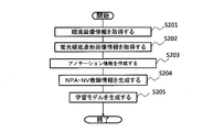
- the server 1 is a server that manages the information processing system shown in FIG. 1 and executes various processes such as NPA ⁇ NV existence probability map generation processing, accompanying finding existence probability map generation processing, estimated NPA ⁇ NV identification processing, and the like. .
- NPA ⁇ NV existence probability map generation process refers to a series of processes from the generation of NPA ⁇ NV teacher information to the generation of the NPA ⁇ NV existence probability map among the processes executed by the server 1.
- NPA / NV teacher information means the existence probability (hereinafter “NPA / non-perfusion area”) (hereinafter referred to as “retina nonperfusion area” or “NPA”) in the fundus image information of the patient It refers to teacher information in computing “presence probability” and “presence probability of neovascularization (NV / neovascularization)”.
- NPA ⁇ NV teacher information is generated based on fluorescence fundus angiographic image information and NPA ⁇ NV annotation information attached to this information.
- Retinal nonperfusion region refers to a region of circulatory failure of the retina resulting from retinal vascular occlusion in an ischemic eye disease.
- the “NPA ⁇ NV presence probability map” is image information in which the NPA presence probability and the NV presence probability are identified and displayed in the fundus image information.
- the “fundus image information” refers to image information based on a fundus image.
- Fluorescent fundus angiographic image information refers to information based on a fluorescent fundus angiographic image.
- the “NPA / NV annotation information” refers to the diagnostic note of the ophthalmologist D regarding at least one of the retinal nonperfusion area (NPA) and the neovascularization (NV) attached to the fluorescence fundus angiographic image information.
- the “neovasculature” is a further progression of retinal circulatory failure and ischemia in the retinal nonperfusion region.
- the specific process flow of the NPA / NV existing probability map generation process will be described later with reference to the flowchart of FIG. 4.
- the “accompanying finding presence probability map generation process” refers to a series of processes from the process performed by the server 1 until the accompanying finding existence probability map is generated after the accompanying finding teacher information is generated.
- the "accompanying finding teacher information” refers to teacher information when calculating the existence probability of the accompanying finding in the fundus image information of the patient.
- “accompanying finding teacher information” refers to teacher information generated based on fluorescence fundus angiographic image information and fundus image information, and accompanying finding annotation information attached to the image information.
- the “consent finding annotation information” refers to the retinal nonperfusion area (NPA) in the diagnostic notes in which the ophthalmologist D has made the “not normal” determination with respect to the fluorescence fundus angiographic image information and the fundus image information. Or anything other than a diagnostic note on neovascularization (NV).
- NPA retinal nonperfusion area
- NV neovascularization
- information such as capillary aneurysm, fundus hemorrhage, hard vitiligo, soft vitiligo, vein abnormality, intraretinal small blood vessel abnormality, vitreous hemorrhage, proliferative membrane, retinal detachment are all examples of “accompanying finding annotation information”.
- the “accompanying finding presence probability map” is image information (not shown) in which the presence probability of the appending finding is identified and displayed on the fundus image information.
- the flow of a specific process of the incidental finding presence probability map generation process will be described later with reference to the flowchart of FIG.
- the “estimated NPA / NV identification process” is an area estimated to correspond to the retinal nonperfusion area (NPA) in the fundus image information based on the NPA presence probability in the process executed by the server 1 It refers to a series of processes until NPA is specified as NPA, and a region in the fundus image information that is estimated to be a neovascular (NV) is specified as estimated NV based on the NV existence probability.
- NPA retinal nonperfusion area
- NV neovascular
- the ophthalmologist terminal 2 is an information processing apparatus operated by the ophthalmologist D, and includes, for example, a personal computer. In the ophthalmologist terminal 2, transmission of NPA ⁇ NV annotation information and incidental finding annotation information to the server 1, acquisition of information on the estimated NPA ⁇ NV specified by the server 1, and the like are performed. The various information acquired by the ophthalmologist terminal 2 is output from the ophthalmologist terminal 2 and used for medical examination by the ophthalmologist D.
- the examination device 3 is composed of various devices used in the eye examination of a patient.
- the examination device 3 transmits, to the server 1, each of fundus image information obtained by imaging in a fundus examination and fluorescence fundus angiographic image information obtained by imaging in a fluorescence fundus angiography examination.
- FIG. 2 is a block diagram showing the hardware configuration of the server 1 in the information processing system of FIG.
- the server 1 includes a central processing unit (CPU) 11, a read only memory (ROM) 12, a random access memory (RAM) 13, a bus 14, an input / output interface 15, an output unit 16, and an input unit 17. , A storage unit 18, a communication unit 19, and a drive 20.
- CPU central processing unit
- ROM read only memory
- RAM random access memory
- the CPU 11 executes various processes in accordance with a program stored in the ROM 12 or a program loaded from the storage unit 18 into the RAM 13. Data and the like necessary for the CPU 11 to execute various processes are also stored in the RAM 13 as appropriate.
- the CPU 11, the ROM 12 and the RAM 13 are connected to one another via a bus 14.
- An input / output interface 15 is also connected to the bus 14.
- An output unit 16, an input unit 17, a storage unit 18, a communication unit 19 and a drive 20 are connected to the input / output interface 15.
- the output unit 16 is configured by various liquid crystal displays or the like, and outputs various information.
- the input unit 17 is made of various types of hardware lead and the like, and inputs various information.
- the storage unit 18 is configured by a DRAM (Dynamic Random Access Memory) or the like, and stores various data.
- the communication unit 19 controls communication with another device via the network N including the Internet.
- the drive 20 is provided as needed.
- a removable medium 30 made of a magnetic disk, an optical disk, a magneto-optical disk, a semiconductor memory or the like is appropriately attached to the drive 20.
- the program read from the removable media 30 by the drive 20 is installed in the storage unit 18 as necessary.
- the removable media 30 can also store various data stored in the storage unit 18 in the same manner as the storage unit 18.
- NPA ⁇ NV existence probability map generation processing is a functional block diagram which shows an example of a functional structure for implement
- the image acquisition unit 101, the annotation acquisition unit 102, and the teacher information generation unit 103 and the operation unit 104 function.
- the image acquisition unit 101, the annotation acquisition unit 102, the teacher information generation unit 103, and the calculation unit 104 function.
- the estimated NPA ⁇ NV identification process is performed, the estimated NPA ⁇ NV identifying unit 106 functions.
- the estimated NPA ⁇ NV display control unit 107 functions.
- An image DB 401, an annotation DB 402, and a teacher DB 403 are provided in one area of the storage unit 18 (FIG. 2).
- the storage unit 18 may be disposed in the ophthalmologist terminal 2 instead of the server 1.
- the image acquisition unit 101 acquires fluorescent fundus angiographic image information of the patient and fundus image information of the patient.
- the fluorescence fundus imaging image information and the fundus oculi image information acquired by the image acquiring unit 101 are stored and managed in the image DB 401, respectively.
- fluorescence fundus angiography examination of a patient when a fluorescence fundus angiogram image of a patient is imaged by the examination device 3, fluorescence fundus angiogram image information based on the fluorescence fundus angiogram is transmitted to the server 1.
- fundus image information based on the fundus image is transmitted to the server 1.
- the image acquisition unit 101 of the server 1 acquires the fluorescent fundus angiographic image information and the fundus image information transmitted from the examination device 3 to the server 1 and stores the image information in the image DB 401.
- the server 1 can accurately manage the patient's fluorescent fundus angiographic image information and fundus image information without leakage.
- the annotation acquisition unit 102 performs the NPA ⁇ NV annotation on the diagnostic note of the ophthalmologist D regarding at least one of the retinal nonperfusion area (NPA) and the neovascularization (NV), which is attached to the fluorescent fundus imaging image information of the patient. Acquire as information.
- NPA retinal nonperfusion area
- NV neovascularization
- the ophthalmologist terminal 2 Based on the operation of the ophthalmologist D, the diagnostic note is transmitted to the server 1 as NPA ⁇ NV annotation information.
- the annotation acquisition unit 102 of the server 1 acquires the NPA ⁇ NV annotation information transmitted from the ophthalmologist terminal 2 and stores this information in the annotation DB 402.
- the fluorescence fundus angiographic image information and the NPA ⁇ NV annotation information attached to the image information are linked to each other and managed.
- the server 1 uses the diagnosis notes of the ophthalmologist D regarding at least one of the retinal nonperfusion area (NPA) and the neovascularization (NV) attached to the fluorescence fundus angiographic image information as NPA and NV annotation information. It can be managed without omission.
- the annotation acquisition unit 102 acquires, as incidental finding annotation information, a diagnostic note of the ophthalmologist D regarding the incidental finding attached to the fluorescent fundus angiographic image and the fundus oculi image. Specifically, in the case where a diagnosis note of the ophthalmologist D regarding incidental findings is attached to the fluorescence fundus angiographic image information and the fundus image information, the ophthalmologist terminal 2 performs the diagnosis based on the operation of the ophthalmologist D. The note is sent to the server 1 as incidental finding annotation information.
- the annotation acquisition unit 102 of the server 1 acquires the incidental finding annotation information transmitted from the ophthalmologist terminal 2 and stores the information in the annotation DB 402.
- the fluorescence fundus angiographic image information and the fundus oculi image information, and the incidental finding annotation information attached to the image information are linked to each other and managed.
- the server 1 can manage, without omission, diagnostic notes of the ophthalmologist D regarding fluorescent fundus angiographic image information and incidental findings attached to the fundus image information as incidental observation annotation information.
- the teacher information generation unit 103 is an NPA NV teacher who becomes teacher information for calculating the NPA existence probability and the NV existence probability based on the fluorescence fundus angiogram image information and the NPA ⁇ NV annotation information corresponding to this information. Generate information. That is, in the image DB 401, fluorescent fundus angiographic image information obtained from a plurality of patients is accumulated, and in the annotation DB 402, NPA ⁇ NV annotation information is accumulated. The teacher information generation unit 103 generates NPA ⁇ NV teacher information to be teacher information when calculating the existence probability of NPA ⁇ NV in fundus image information based on the information accumulated in the database.
- the server 1 can generate and accumulate teacher information for calculating the NPA presence probability and the NV presence probability in the fundus image information of the patient.
- the teacher information generation unit 103 generates incidental finding teacher information based on the fluorescence fundus angiographic image information and the fundus oculi image information, and the incidental finding annotation information corresponding to the image information. That is, fundus image information and fluorescence fundus angiographic image information obtained from a plurality of patients are accumulated in the image DB 401, and incidental finding annotation information is accumulated in the annotation DB 402.
- the teacher information generation unit 103 generates, based on the information accumulated in the database, incidental finding teacher information that is to be teaching information when calculating the existence probability of the incidental finding in the fundus image information. Thereby, the server 1 can accumulate teacher information for calculating the existence probability of the incidental finding in the fundus image information of the patient.
- the calculation unit 104 calculates the NPA existence probability and the NV existence probability based on at least the NPA ⁇ NV teacher information.
- the computing unit 104 computes the NPA presence probability and the NV presence probability based on the accompanying finding presence probability map and the NPA ⁇ NV teacher information. Do.
- the specific method for calculating the NPA presence probability and the NV presence probability is not particularly limited. For example, a feature common to the fundus image having NPA and NV is extracted from NPA and NV teacher information, and the matching degree with the feature is normalized as to whether the patient's fundus image information has the feature or not. NPA existence probability and NV existence probability may be calculated.
- the NPA presence probability and the NV presence probability may be calculated using a deep learning technique. In this way, a reference is set for identifying a region estimated to correspond to the retinal nonperfusion region (NPA) and a region estimated to correspond to the neovascular (NV) in the fundus image information. It becomes possible.
- NPA retinal nonperfusion region
- NV neovascular
- the calculation unit 104 also calculates the existence probability of the incidental finding in the fundus image information based on the incidental finding teacher information.
- the specific method of calculating the existence probability of incidental findings is not particularly limited. For example, a feature common to the fundus image having the accompanying finding is extracted from the accompanying finding teacher information, and the patient's fundus image information has the feature or not by normalizing the matching degree to the feature.
- the existence probability may be calculated.
- a deep learning technique may be used to calculate the presence probability of incidental findings. In this way, a reference is set for identifying a region in which retinal nonperfusion region (NPA) is estimated to be applicable and a region in which it is estimated to be neovascularization (NV) in the fundus image information. Is possible.
- NPA retinal nonperfusion region
- NV neovascularization
- the map generation unit 105 generates an NPA ⁇ NV presence probability map as image information in which the NPA presence probability and the NV presence probability are identified and displayed in the fundus image information. Specifically, image information such as NPA ⁇ NV existence probability map E illustrated in FIG. 8 is generated. This makes it possible to generate information as a basis for estimating the retinal nonperfusion area (NPA) in the fundus image information and the presence of a new blood vessel (NV).
- the method for identifying and displaying the NPA presence probability and the NV presence probability in the fundus image information is not particularly limited.
- the NPA presence probability and the NV presence probability may be identified and displayed based on a difference in color, or the NPA presence probability and the NV presence probability may be identified and displayed based on color density.
- the map generation unit 105 generates an accompanying finding existence probability map (not shown) as image information in which the incident finding existence probability is identified and displayed on the fundus image information. This makes it possible to generate information as a basis for estimating the retinal nonperfusion area (NPA) in the fundus image information and the presence of a new blood vessel (NV).
- the method for identifying and displaying the incidental finding presence probability in the fundus image information is not particularly limited.
- the incidental finding presence probability may be identified and displayed based on a difference in color, or the incidental finding presence probability may be identified and displayed based on color shading.
- the estimated NPA / NV identifying unit 106 identifies, as the estimated NPA, a region estimated to correspond to the retinal nonperfusion region (NPA) in the fundus image information based on the NPA existing probability and the NV existing probability.
- An area estimated to correspond to a blood vessel (NV) is identified as an estimated NV.
- a region where the NPA presence probability and the NV presence probability exceed a predetermined threshold is assumed to correspond to a retinal nonperfusion region (NPA) (estimated NPA) Or as an area (estimated NV) estimated to correspond to a neovascular (NV).
- the threshold can be arbitrarily changed by the judgment of the ophthalmologist D.
- NPA retinal nonperfusion area
- NV new blood vessels
- the estimated NPA / NV display control unit 107 executes control to display the estimated NPA area and the estimated NV area on the fundus image information. In this way, an area (estimated NPA) in which the presence of retinal nonperfusion is estimated and an area (estimated NV) in which the presence of new blood vessels (NV) is estimated are displayed superimposed on the image information based on the fundus image. Can.
- FIG. 4 is a flowchart for explaining the flow of a series of processes performed by the server 1 of FIG.
- step S ⁇ b> 1 the image acquisition unit 101 determines whether or not the fluorescence fundus imaging image information has been transmitted from the examination device 3. If the fluorescence fundus imaging image information has been transmitted, it is determined as YES in step S1, and the process proceeds to step S2. On the other hand, if the fluorescence fundus angiographic image information has not been transmitted, it is determined as NO in step S1, and the process returns to step S1. That is, the determination process of step S1 is repeated until the fluorescence fundus imaging image information is transmitted. Thereafter, when the fluorescence fundus imaging image information is transmitted, it is determined as YES in Step S1, and the process proceeds to Step S2. In step S2, the image acquisition unit 101 acquires the transmitted fluorescence fundus imaging image information.
- step S3 the annotation acquisition unit 102 determines whether NPA ⁇ NV annotation information has been transmitted from the ophthalmologist terminal 2. If NPA ⁇ NV annotation information has been transmitted, it is determined as YES in step S3, and the process proceeds to step S4. On the other hand, if NPA ⁇ NV annotation information has not been transmitted, it is determined as NO in step S3, and the process is returned to step S3. That is, until the NPA ⁇ NV annotation information is transmitted, the determination process of step S3 is repeated. Thereafter, when NPA ⁇ NV annotation information is transmitted, it is determined as YES in step S3, and the process proceeds to step S4. In step S4, the annotation acquisition unit 102 acquires the transmitted NPA ⁇ NV annotation information.
- step S5 the teacher information generation unit 103 generates NPA ⁇ NV teacher information based on the fluorescence fundus angiogram image information and the NPA ⁇ NV annotation information corresponding to the fluorescence fundus angiogram image information.
- step S6 the image acquisition unit 101 determines whether or not fundus image information has been transmitted from the examination device 3. If the fundus oculi image information has been transmitted, it is determined as YES in step S6, and the process proceeds to step S7. On the other hand, when the fundus oculi image information has not been transmitted, it is determined as NO in step S6, and the process is returned to step S6. That is, until the fundus oculi image information is transmitted, the determination process of step S6 is repeated. Thereafter, when fundus oculi image information is transmitted, it is determined as YES in step S6, and the process proceeds to step S7. In step S7, the image acquisition unit 101 acquires the transmitted fundus image information.
- step S8 the annotation acquisition unit 102 determines whether or not the accompanying finding annotation information has been transmitted from the ophthalmologist terminal 2. If the incidental finding annotation information has been transmitted, it is determined as YES in step S8, and the process proceeds to step S9. On the other hand, if the incidental finding annotation information has not been sent, it is determined as NO in step S8, and the process skips steps S9 to S11 and proceeds to step S12. In step S9, the annotation acquisition unit 102 acquires incidental finding annotation information. In step S10, the teacher information generation unit 103 generates the accompanying finding teacher information based on the fluorescence fundus angiogram image information and the NPA ⁇ NV annotation information corresponding to the fluorescence fundus angiogram image information.
- step S11 the calculation unit 104 calculates the existence probability of the incidental finding in the fundus image information based on the incidental finding teacher information.
- step S12 the map generation unit 105 generates an incidental finding presence probability map as image information in which the incidental finding presence probability is identified and displayed in the fundus image information.
- step S13 the computing unit 104 computes the NPA presence probability and the NV presence probability based on at least the NPA ⁇ NV teacher information.
- the operation unit 104 calculates the NPA presence probability and the NV presence probability based on the NPA ⁇ NV teacher information and the incidental finding presence probability map.
- the map generation unit 105 generates an NPA ⁇ NV presence probability map as image information in which the NPA presence probability and the NV presence probability are identified and displayed in the fundus image information.
- step S ⁇ b> 15 the estimated NPA / NV identifying unit 106 estimates a region estimated to correspond to the retinal nonperfusion region (NPA) in the fundus image information based on the NPA presence probability and the NV presence probability. And identify a region estimated to correspond to a neovascular (NV) as an estimated NV.
- step S16 the estimated NPA / NV display control unit 107 executes control to cause the fundus oculi image information to display the estimated NPA and the NV region.
- step S17 the server 1 determines whether an instruction to end the process has been issued. If there is no instruction to end the process, it is determined as NO in step S17, and the process returns to step S1. On the other hand, if an instruction to end the process has been issued, it is determined as YES in step S17, and the process ends.
- the server 1 executes the series of processes as described above, the estimated NPA area and the estimated NV area are displayed in the fundus image information.
- FIG. 5 is a diagram showing the flow of various information in the process executed by the server 1.
- the fluorescence fundus imaging image information based on the fluorescence fundus imaging image is acquired by the server 1.
- This fluorescence fundus imaging image information is attached with a diagnostic note of the ophthalmologist D regarding at least one of a retinal nonperfusion area (NPA) and a neovascularization (NV).
- NPA retinal nonperfusion area
- NV neovascularization
- This diagnostic note constitutes NPA ⁇ NV teacher information together with fluorescence fundus angiographic image information as NPA ⁇ NV annotation information.
- fundus image information based on the fundus image is acquired by the server 1.
- the fundus oculi image information and the NPA ⁇ NV teacher information are used for calculation processing by the NPA ⁇ NV annotation program of the calculation unit 104.
- an NPA ⁇ NV existing probability map is generated.
- estimated NPA and estimated NV in the fundus image information are identified.
- the ophthalmologist D's diagnostic note regarding incidental findings may be attached to the fluorescence fundus imaging image information and the fundus image information.
- the diagnostic note in this case constitutes incidental finding teacher information together with fluorescence fundus angiographic image information and fundus image information as incidental finding annotation information.
- the fundus oculi image information and the NPA ⁇ NV teacher information are used for calculation processing by the incidental findings determination program of the calculation unit 104.
- an incidental occurrence probability map is generated.
- the incidental finding presence probability map is generated, the estimated NPA and the estimated NV in the fundus image information are specified based on the incidental finding presence probability map and the NPA ⁇ NV teacher information.
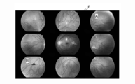
- FIG. 6 is a diagram showing an example of fundus image information acquired in the process executed by the server 1.
- FIG. 7 is a view showing an example of fluorescence fundus angiographic image information acquired in the process executed by the server 1.
- fundus image information as shown in FIG. 6 is obtained.
- the ophthalmologist D consults with reference to fundus image information as shown in FIG.
- FIG. 6 in the fundus image information, only findings such as hemorrhage and vitiligo resulting from perfusion abnormality are displayed, and it is difficult to read hemodynamics and circulatory abnormality sites. Therefore, by performing a fluorescence fundus angiography examination, fluorescence fundus angiographic image information as shown in FIG. 7 is obtained.
- the retinal fundus angiography image information can clearly discriminate retinal circulatory dynamics.
- the server 1 uses the NPA ⁇ NV teacher information generated based on the fluorescence fundus angiographic image information obtained from the plurality of accumulated patients and the NPA ⁇ NV annotation information attached to each of the information. , NPA ⁇ NV existence probability map generation processing. As a result, it is possible to simply identify a circulatory abnormality finding from a fundus image that can be easily taken at a nearby clinic or medical checkup, etc., without performing a heavy burden fluorescence fundus imaging examination.
- FIG. 8 is a diagram showing an example of the NPA ⁇ NV presence probability map output in the NPA ⁇ NV presence probability map generation process executed by the server 1.
- the NPA-NV presence probability map E shown in FIG. 8 is image information in which the NPA presence probability and the NV presence probability are identified and displayed in the fundus image information.
- the NPA-NV presence probability map E can distinguish and display the NPA presence probability and the NV presence probability based on the difference in color and the color density. For example, an area indicated by a warm color may have a high NPA existence probability and an NV existence probability, and an area indicated by a cold color may be identified and displayed as having a low NPA existence probability and an NV existence probability.
- the identification indication that the dark area has a lower NPA existence probability and the NV existence probability than the light color area. Is also possible. This makes it possible to generate information as a basis for estimating the retinal nonperfusion area (NPA) in the fundus image information and the presence of a new blood vessel (NV).
- NPA retinal nonperfusion area
- FIG. 9 is a diagram illustrating an example of estimated NPA identified in the estimated NPA / NV identification process performed by the server 1 and an example of estimated NV.
- the server 1 specifies an area estimated to correspond to the retinal nonperfusion area (NPA) in the fundus image information as the estimated NPA based on the contents of the NPA ⁇ NV existence probability map, and corresponds to the neovascular (NV)
- An area estimated to be estimated is specified as an estimated NV.
- an area A indicated by a broken line may be an estimated NPA, and an area B may be an estimated NV.
- the estimated NPA and the estimated NV can be displayed superimposed on the fundus image information.
- the region where the presence of retinal nonperfusion is estimated from the fundus image obtained by imaging the patient's fundus, and the presence of a neovascular without performing a fluorescence fundus angiography examination that requires a special fundus camera or a diagnostic device It is possible to early and easily identify the area where is estimated.
- the image acquisition unit 101 is configured to acquire such information when various image information is transmitted from the inspection device 3, but when imaging by the inspection device 3 is performed, the image The acquisition unit 101 may voluntarily take various image information.
- the annotation acquiring unit 102 is configured to acquire various types of annotation information when the various types of annotation information are transmitted from the ophthalmologist terminal 2, but when various types of annotation information are input to the ophthalmologist terminal 2, The annotation acquisition unit 102 may voluntarily take various annotation information.
- each hardware configuration shown in FIG. 2 is merely an example for achieving the object of the present invention, and is not particularly limited.
- the functional block diagram shown in FIG. 3 is merely an example and is not particularly limited. That is, it is sufficient if the information processing system is equipped with a function capable of executing the above-described series of processes as a whole, and what functional block is used to realize this function is not particularly limited to the example of FIG. .
- the location of the functional block is not limited to the location shown in FIG. 3 and may be arbitrary.
- at least a part of the functional blocks of the server 1 may be provided in the ophthalmologist terminal 2 or the inspection device 3.
- One functional block may be configured as a single piece of hardware or may be configured as a combination with a single piece of software.
- a program constituting the software is installed on a computer or the like from a network or a recording medium.
- the computer may be a computer incorporated in dedicated hardware.
- the computer may be a computer capable of executing various functions by installing various programs, such as a general-purpose smartphone or personal computer other than a server.
- a recording medium including such a program is distributed not only by a removable medium separately from the apparatus main body to provide the program to each user, but is configured not only by removable media but also by each user while being incorporated in the apparatus main body. It comprises the provided recording medium and the like.
- the processing performed chronologically according to the order is, of course, parallel or individually not necessarily necessarily chronologically processing. It also includes the processing to be performed.
- the image acquisition unit 101 determines whether fundus image information has been transmitted from the examination device 3, and acquires fundus image information in step S7.
- the incidental finding presence probability map generation process is executed, it is sufficient for the fundus image information to be appropriately managed when the incidental observation teacher information is generated.
- the incidental finding presence probability map generation process is not executed, it is sufficient if the NPA presence probability and the NV presence probability are appropriately managed at the time when they are calculated.
- the fundus oculi image information is stored and managed in the image DB 401 from any time point before the incidental finding teacher information is generated in step S10. Good. Further, when the incidental finding teacher information is not generated, it may be stored and managed in the image DB 401 from any point before the NPA presence probability and the NV presence probability are calculated in step S13.
- the program to which the present invention is applied is In a computer that controls an information processing apparatus, Acquiring a fluorescence fundus imaging image (for example, step S2 in FIG. 4) for acquiring fluorescence fundus imaging image information (for example, fluorescence fundus imaging image information C in FIG. 7); NPA / NV annotation acquisition to obtain an ophthalmologist's diagnostic note on at least one of retinal nonperfusion area (NPA) and neovascularization (NV) attached to the fluorescence fundus angiographic image information as NPA / NV annotation information Step (e.g. step S4 in FIG.
- NPA retinal nonperfusion area
- NV neovascularization
- NPA ⁇ NV teacher information generation step for example, step S5 in FIG. 4 for generating NPA ⁇ NV teacher information to be teacher information for calculation;
- a fundus image acquisition step for example, step S7 in FIG. 4 for acquiring fundus image information (for example, fundus image information F in FIG. 6);
- NPA / NV presence probability calculation step for example, FIG.
- an area estimated to correspond to the retinal nonperfusion area (NPA) in the fundus image information is specified as an estimated NPA
- An estimated NPA / NV identifying step (for example, step S15 in FIG. 4) of identifying an area estimated to correspond to a neovascular (NV) as an estimated NV; including.
- NPA ⁇ NV existence probability map (for example, NPA ⁇ NV existence probability map E in FIG. 8) is generated by identifying and displaying the NPA existence probability and the NV existence probability in the fundus image information It is possible to execute control processing further including a probability map generation step (for example, step S14 of FIG. 4). This makes it possible to generate information as a basis for estimating the retinal nonperfusion area (NPA) in the fundus image information and the presence of a new blood vessel (NV).
- NPA retinal nonperfusion area
- An accompanying annotation acquisition step (for example, step S9 in FIG. 4) of acquiring the diagnostic note of the ophthalmologist regarding the incidental finding attached to the fluorescence fundus angiographic image information and the fundus image information as incidental finding annotation information;
- the presence probability of the incidental finding in the fundus image information is calculated based on the fluorescence fundus angiographic image information and the fundus oculi image information, the fluorescence fundus angiographic image information, and the incidental finding annotation information corresponding to the fundus image information.
- An accompanying finding teacher information generating step (for example, step S10 in FIG. 4) of generating the accompanying finding teacher information which is to be teacher information for
- An accompanying finding presence probability calculating step (for example, step S11 in FIG.
- NPA ⁇ NV existence probability calculating step Control for calculating the existence probability of the retinal nonperfusion area (NPA) in the fundus image information and the existence probability of a neovascular (NV) based on the existence probability of the incidental finding and the NPA / NV teacher information Processing can be performed.
- NPA retinal nonperfusion area
- NV neovascular
- the fundus image information may further include an accompanying finding presence probability map generation step (for example, step S12 in FIG. 4) of generating a accompanying finding presence probability map in which the presence probability of the accompanying finding is identified and displayed.
- an accompanying finding presence probability map generation step for example, step S12 in FIG. 4 of generating a accompanying finding presence probability map in which the presence probability of the accompanying finding is identified and displayed.
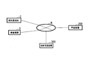
- FIG. 10 is a block diagram of an information processing system according to a modification of the embodiment of the present invention.
- An information processing system according to a modification of an embodiment of the present invention includes an ophthalmologist terminal 2, an inspection device 3, a learning device 200, and a diagnosis support device 300. These devices are connected to one another via a network N.
- the learning apparatus 200 uses the fundus image and the blood circulation abnormality region in the fundus image based on the fundus image which is an image of the fundus and the blood circulation abnormality region specified based on the fluorescence fundus angiographic image of the fundus.
- a learning model representing a relationship is generated by learning.
- the blood circulation abnormality area is an area in which the blood circulation caused by the blood disorder on the retina which is generated in the eye ischemic disease such as diabetic retinopathy is abnormal.
- the learning apparatus 200 acquires information indicating the fundus image of the patient and information indicating the fluoroscopic fundus image of the patient, associates the information indicating the acquired fundus image with the information indicating the fluoroscopic imaging image, Remember.
- the examination device 3 captures a fundus image of the patient, includes the patient ID and information indicating the captured fundus image, and the fundus image notification information addressed to the learning device 200 Are created, and the created fundus image notification information is transmitted to the learning apparatus 200.
- the examination device 3 captures the fluorescence fundus angiogram of the patient, includes the patient ID, and information indicating the captured fluorescence fundus angiogram, and the fluorescence directed to the learning device 200.
- the fundus oculi contrast image notification information is created, and the created fluorescence fundus contrast image notification information is transmitted to the learning device 200.
- the learning device 200 includes a patient ID included in fundus image notification information transmitted from the examination device 3 to the learning device 200, information indicating a fundus image, a patient ID included in a fluorescence fundus angiogram notification information, and a fluorescence fundus image
- the information indicating the image is acquired, and the acquired patient ID, the information indicating the fundus image, and the information indicating the fluorescence fundus angiogram are associated and stored.
- the learning apparatus 200 performs NPA ⁇ NV annotations on the diagnosis notes of the ophthalmologist D regarding the retinal nonperfusion area (NPA) and / or the neovascularization (NV), which are added to the patient's fluorescent fundus angiographic image. Acquire as information.
- NPA retinal nonperfusion area
- NV neovascularization
- the ophthalmologist terminal 2 is an ophthalmologist Based on the operation of the doctor D, NPA ⁇ NV annotation notification information including the patient ID and the relevant diagnosis note and addressed to the learning device 200 is created, and the created NPA ⁇ NV annotation notification information is sent to the learning device 200. Send.
- the learning device 200 receives the NPA ⁇ NV annotation notification information transmitted by the ophthalmologist terminal 2, and stores the NPA ⁇ NV annotation information included in the received NPA ⁇ NV annotation notification information.
- the information indicating the fluorescence fundus angiogram and the NPA ⁇ NV annotation information attached to the fluorescence fundus angiogram are associated with each other and stored.
- the learning device 200 acquires the diagnosis note of the ophthalmologist D regarding the incidental finding attached to the fundus image and the fluorescent fundus angiographic image as incidental finding annotation information. Specifically, when a diagnostic note of the ophthalmologist D regarding the accompanying findings is attached to the information indicating the fluorescence fundus angiogram and the information indicating the fundus image, the ophthalmologist terminal 2 is based on the operation of the ophthalmologist D. In addition, the accompanying observation annotation notification information including the patient ID and the diagnosis note and addressed to the learning device 200 is created, and the created accompanying observation annotation notification information is sent to the learning device 200.
- the learning device 200 receives the incidental finding annotation notification information sent by the ophthalmologist terminal 2, acquires the patient ID included in the received incidental finding annotation notification information, and the incidental finding annotation information, and the acquired patient ID, The observation annotation information is stored. Note that the information indicating the fundus image, the information indicating the fluorescence fundus angiogram, and the incidental finding annotation information are associated with each other and stored.
- the learning apparatus 200 acquires and acquires information indicating a fundus image, information indicating a fluorescent fundus angiographic image associated with the information indicating the fundus image, NPA / NV annotation information, and incidental finding annotation information.
- the blood circulation abnormality region is specified based on the information indicating the fluorescence fundus angiographic image, the NPA ⁇ NV annotation information, and the incidental finding annotation information.
- the learning device 200 generates NPA ⁇ NV learning information in which information representing a fundus image is associated with a blood circulation abnormal region identified based on a fluorescence fundus angiographic image corresponding to the fundus image, and the generated NPA ⁇ NV Store learning information.
- the learning apparatus 200 uses, as input information, information indicating a fundus image included in the NPA and NV learning information, and uses the blood circulation abnormality region identified based on the fluorescence fundus angiographic image corresponding to the fundus image as teacher information. And a learning model that represents the relationship between the blood circulation abnormal region in the fundus image by learning.
- the specific method for generating the learning model is not particularly limited. For example, features common to the fundus image having a blood circulation abnormality region may be extracted from the NPA ⁇ NV learning information, and the relationship between the extracted common features and the blood circulation abnormality region in the fundus image may be derived.
- the relationship between the fundus oculi image and the blood circulation abnormality region in the fundus oculi image may be derived using a neural network or deep learning (depth learning) technology.
- the learning device 200 stores the generated learning model, and generates learning model notification information including the generated learning model and having the diagnosis support device 300 as a destination, and the generated learning model notification information to the diagnosis support device 300. Send.
- the diagnosis support device 300 receives the learning model transmitted by the learning device 200, and stores the received learning model.
- the ophthalmologist terminal 2 creates patient information including the patient ID and information indicating the fundus image of the patient and having the diagnosis support device 300 as a destination, and transmits the created patient information to the diagnosis support device 300.
- the diagnosis support apparatus 300 receives the patient information transmitted by the ophthalmologist terminal 2, and acquires a patient ID included in the received patient information and information indicating a fundus image of the patient.
- the diagnosis support apparatus 300 identifies a blood circulation abnormality region in the fundus image, based on the information indicating the acquired fundus image, using the stored learning model.
- the diagnosis support device 300 includes a patient's fundus image, information indicating a blood circulation abnormality region in the fundus image identified using a learning model, and a patient ID, and the diagnosis result addressed to the ophthalmologist terminal 2
- the created diagnostic result is transmitted to the ophthalmologist terminal 2.
- the learning device 200 and the diagnosis support device 300 included in the information processing system will be described.
- FIG. 11 is a block diagram showing an example of a learning device according to a modification of the embodiment of the present invention.
- the learning device 200 electrically connects the communication unit 205, the storage unit 210, the operation unit 220, the information processing unit 230, the display unit 240, and each component as shown in FIG. And a bus line 250 such as an address bus or a data bus.
- the communication unit 205 is realized by a communication module.
- the communication unit 205 communicates with external communication devices such as the ophthalmologist terminal 2, the inspection device 3, and the diagnosis support device 300 via the network N.
- the communication unit 205 receives the fundus oculi image notification information transmitted by the examination device 3, and outputs the received fundus oculi image notification information to the information processing unit 230.
- the communication unit 205 receives the fluorescence fundus imaging image notification information transmitted by the examination device 3 and outputs the received fluorescence fundus imaging image notification information to the information processing unit 230.
- the communication unit 205 receives the NPA ⁇ NV annotation notification information transmitted by the ophthalmologist terminal 2, and outputs the received NPA ⁇ NV annotation notification information to the information processing unit 230.
- the communication unit 205 receives the incidental finding annotation notification information transmitted by the ophthalmologist terminal 2, and outputs the received incidental observation annotation notification information to the information processing unit 230.
- the communication unit 205 acquires the learning model notification information output by the information processing unit 230, and transmits the acquired learning model notification information to the diagnosis support apparatus 300.
- the storage unit 210 is realized by, for example, a random access memory (RAM), a read only memory (ROM), a hard disk drive (HDD), a flash memory, or a hybrid storage device in which a plurality of them are combined.
- the storage unit 210 stores a program 211 executed by the information processing unit 230, an application 212, an image DB 213, an annotation DB 214, learning information 215, and a learning model 216.
- the program 211 is, for example, an operating system, located between a user or application program and hardware, provides a standard interface for the user or application program, and at the same time, is efficient for each resource such as hardware. Management.
- the application 212 causes the learning apparatus 200 to receive the fundus oculi image notification information transmitted by the examination device 3, associates the patient ID included in the received fundus oculi image notification information, and the information indicating the fundus oculi image, and stores them.
- the application 212 causes the learning apparatus 200 to receive the fluorescence fundus angiographic image notification information transmitted by the examination device 3, and the patient ID included in the received fluorescence fundus angiogram image notification information and information indicating the fluorescence fundus angiogram. Associate and store.
- the application 212 causes the learning device 200 to receive the NPA ⁇ NV annotation notification information transmitted by the ophthalmologist terminal 2, and associates the patient ID included in the received NPA ⁇ NV annotation notification information with the NPA ⁇ NV annotation information To memorize.
- the application 212 causes the learning device 200 to receive the incidental finding annotation notification information sent by the ophthalmologist terminal 2, and stores the patient ID included in the incidental finding annotation notification information received and the incidental finding annotation information in association with each other. .
- the application 212 causes the learning apparatus 200 to acquire information indicating a fundus image associated with a patient ID, information indicating a fluorescence fundus angiogram, NPA / NV annotation information, and incidental finding annotation information.
- the application 212 causes the learning device 200 to specify the blood circulation abnormality region based on the information indicating the acquired fluorescence fundus angiogram, the NPA ⁇ NV annotation information, and the incidental finding annotation information.
- the application 212 causes the learning device 200 to generate and generate NPA ⁇ NV learning information in which information indicating a fundus image is associated with a blood circulation abnormal region identified based on a fluorescent fundus imaging image corresponding to the fundus image.
- the stored NPA ⁇ NV learning information is stored.
- the application 212 uses the information indicating the fundus image included in the NPA / NV learning information as input information to the learning device 200, and the blood circulation abnormal region specified based on the fluorescence fundus angiographic image corresponding to the fundus image is supervised information
- a learning model a learning model representing the relationship between the fundus image and the blood circulation abnormality region in the fundus image is generated by learning.
- the application 212 causes the learning device 200 to store the generated learning model and to transmit it to the diagnosis support device 300.
- the image DB 213 associates and stores a patient ID, information indicating a fundus image, and information indicating a fluorescence fundus angiogram.
- the annotation DB 214 associates and stores the patient ID, the NPA / NV annotation information, and the incidental finding annotation information.
- the learning information 215 stores NPA ⁇ NV learning information in which information indicating a fundus oculi image is associated with a blood circulation abnormality region identified based on a fluorescent fundus oculi angiographic image corresponding to the fundus oculi image.
- the learning model 216 uses, as input information, information indicating a fundus image included in NPA and NV learning information, and uses the blood circulation abnormality region identified based on the fluorescence fundus angiographic image corresponding to the fundus image as teacher information. And a learning model that represents the relationship between the blood circulation abnormality region in the fundus image
- the operation unit 220 is formed of, for example, a touch panel, detects a touch operation on the screen displayed on the display unit 240, and outputs a detection result of the touch operation to the information processing unit 230.
- the display unit 240 is configured of, for example, a touch panel, and displays a screen that receives information indicating the fundus image received by the learning device 200 and information indicating the fluorescence fundus angiogram. In addition, the display unit 240 displays a screen for receiving an operation for processing the NPA ⁇ NV annotation information received by the learning device 200 and the incidental finding annotation information.
- all or part of the information processing unit 230 may be a functional unit realized by executing a program 211 stored in the storage unit 210 and an application 212 by a processor such as a CPU (Central Processing Unit) (hereinafter referred to as It is called a software function unit).
- a processor such as a CPU (Central Processing Unit) (hereinafter referred to as It is called a software function unit).
- all or part of the information processing unit 230 may be realized by hardware such as LSI (Large Scale Integration), ASIC (Application Specific Integrated Circuit), or FPGA (Field-Programmable Gate Array), and the software function It may be realized by a combination of a part and hardware.
- the information processing unit 230 includes, for example, an image acquisition unit 231, an annotation acquisition unit 232, a learning information generation unit 233, and a learning unit 234.
- the image acquisition unit 231 acquires the fundus oculi image notification information output by the communication unit 205, and acquires a patient ID included in the acquired fundus oculi image notification information and information indicating a fundus oculi image.
- the image acquisition unit 231 associates the acquired patient ID with the information indicating the fundus image and stores the information in the image DB 213.
- the image acquisition unit 231 acquires the fluorescence fundus angiographic image notification information output from the communication unit 205, and acquires the patient ID included in the acquired fluorescence fundus angiogram image notification information and information indicating the fluorescence fundus angiogram.
- the image acquisition unit 231 stores the acquired patient ID in the image DB 213 in association with the information indicating the fluorescence fundus angiogram.
- the annotation acquisition unit 232 acquires the NPA ⁇ NV annotation notification information output by the communication unit 205, and acquires the patient ID included in the acquired NPA ⁇ NV annotation notification information and the NPA ⁇ NV annotation information.
- the annotation acquisition unit 232 associates the acquired patient ID with the NPA ⁇ NV annotation information, and stores it in the annotation DB 214.
- the annotation acquisition unit 232 acquires the incidental finding annotation notification information output from the communication unit 205, and acquires the patient ID included in the acquired incidental finding annotation notification information and the incidental finding annotation information.
- the annotation acquisition unit 232 associates the acquired patient ID with the incidental finding annotation information and stores the associated information in the annotation DB 214.
- the learning information generation unit 233 acquires the patient ID stored in the image DB 213 of the storage unit 210, information indicating a fundus image associated with the patient ID, and information indicating a fluorescence fundus angiogram.
- the learning information generation unit 233 acquires the patient ID stored in the annotation DB 214 of the storage unit 210, the NPA ⁇ NV annotation information associated with the patient ID, and the incidental finding annotation information.
- the learning information generation unit 233 specifies the blood circulation abnormality region based on the information indicating the acquired fluorescence fundus angiogram, the NPA ⁇ NV annotation information, and the incidental finding annotation information.
- FIG. 12 is a view showing an example of a fundus oculi image
- FIG. 13 is a view showing an example of a fluorescent fundus oculi contrast image.
- the learning information generation unit 233 extracts the green component of the fundus image and removes the noise component from the green component extracted fundus image which is the fundus image from which the green component is extracted.
- the learning information generation unit 233 divides the green component extraction fundus image from which the noise component has been removed into rectangles.
- the learning information generation unit 233 resizes the green component extraction fundus image from which the noise component is removed to a predetermined size based on the image divided into rectangles.
- interpolation is performed using an interpolation method such as bicubic interpolation.
- the learning information generation unit 233 extracts the green component of the fluorescence fundus angiogram and removes the noise component from the green component extracted fluorescence fundus angiogram which is the fluorescence fundus angiogram from which the green component is extracted.
- the learning information generation unit 233 divides the green component-extracted fluorescence fundus angiographic image from which the noise component has been removed into rectangles.
- the learning information generation unit 233 resizes the green component-extracted fluorescence fundus angiographic image from which the noise component has been removed, to a predetermined size based on the image divided into rectangles.
- interpolation is performed using an interpolation method such as bicubic interpolation.
- the learning information generation unit 233 corrects the rotation component so that the position of the eyeball matches the green component extraction fundus image from which the noise component has been removed and the green component extraction fluorescence fundus contrast image from which the noise component has been removed. Resize to the size of.
- the learning information generation unit 233 corrects the rotation component so that the position of the eyeball matches, and the green component extraction fundus image from which the noise component resized to the predetermined size is removed and the green component extraction fluorescence fundus from which the noise component is removed A blood circulation abnormality region is identified based on the contrast image.
- FIG. 14 is a diagram showing an example of the blood circulation abnormality region.
- the learning information generation unit 233 generates NPA ⁇ NV learning information in which information indicating a fundus image is associated with a blood circulation abnormality region identified based on a fluorescence fundus angiographic image corresponding to the fundus image and generated.
- the NV learning information is stored in the learning information 215 of the storage unit 210. Returning to FIG. 11, the description will be continued.
- the learning unit 234 acquires the NPA ⁇ NV learning information stored in the learning information 215 of the storage unit 210.
- the learning unit 234 acquires information indicating the fundus image included in the acquired NPA and NV learning information, and information indicating the blood circulation abnormality region.
- the learning unit 234 uses the information indicating the acquired fundus image as input information, and the blood circulation abnormal region identified based on the fluorescence fundus angiographic image corresponding to the fundus image as teacher information, in the fundus image and the fundus image
- a learning model representing a relationship with a blood circulation abnormality region is generated by learning.
- the patch size is set to 64 px ⁇ 64 px
- stride the interval for moving the frame for patch extraction
- the generated patches are divided into two groups: those containing positive areas and those not containing any. Choose patches so that the proportions of both groups used for learning are equal.
- a phenomenon in which a neural network performs well only for training data itself or an image very similar to it, and exhibits extremely low performance for an unknown image is over-fitting. To solve this problem, it is improved by collecting more samples and adding geometric operations such as rotation to the training data.
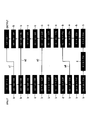
- FIG. 15 is a diagram showing an example of the structure of a neural network.
- An example of the structure of a neural network is based on U-Net.
- batch normalization was performed using an activation function ReLU. However, in the final convolution layer, batch normalization was not performed using sigmoid as an activation function.
- arrows shown by a1, a2, a3 and a4 represent skip connection by concatenation. This is considered to contribute to the restoration of the position information of the image.
- the learning unit 234 stores the generated learning model in the learning model 216 of the storage unit 210.
- the learning unit 234 generates learning model notification information including the generated learning model and having the diagnosis support device 300 as a destination, and outputs the generated learning model notification information to the communication unit 205.
- FIG. 16 is a block diagram showing an example of a diagnosis support apparatus of a modification of the embodiment of the present invention.
- the diagnosis support apparatus 300 electrically connects the communication unit 305, the storage unit 310, the operation unit 320, the information processing unit 330, the display unit 340, and each component as shown in FIG. And bus lines 350 such as an address bus and a data bus.
- the communication unit 305 is realized by a communication module.
- the communication unit 305 communicates with an external communication device such as the ophthalmologist terminal 2 and the learning device 200 via the network N. Specifically, the communication unit 305 receives the learning model notification information transmitted by the learning device 200, and outputs the received learning model notification information to the information processing unit 330.
- the communication unit 305 receives the patient information transmitted by the ophthalmologist terminal 2 and outputs the received patient information to the information processing unit 330.
- the communication unit 305 acquires the diagnostic information output by the information processing unit 230, and transmits the acquired diagnostic information to the ophthalmologist terminal 2.
- the storage unit 310 is realized by, for example, a RAM, a ROM, an HDD, a flash memory, or a hybrid storage device in which a plurality of these are combined.
- the storage unit 310 stores a program 311 executed by the information processing unit 330, an application 312, and a learning model 216.
- the program 311 is, for example, an operating system, located between a user or application program and hardware, provides a standard interface for the user or application program, and at the same time, is efficient for each resource such as hardware. Management.
- the application 312 causes the diagnosis support device 300 to receive the learning model notification information transmitted by the learning device 200, and stores the learning model included in the received learning model notification information.
- the application 312 causes the diagnosis support apparatus 300 to receive the patient information transmitted by the ophthalmologist terminal 2, and acquires the patient ID included in the received patient information and the fundus image.
- the application 312 causes the diagnosis support device 300 to specify the blood circulation abnormality region in the acquired fundus image, using the stored learning model.
- the application 312 includes, in the diagnosis support apparatus 300, information indicating the blood circulation abnormality region in the fundus image of the patient identified using the fundus image of the patient and the learning model, and the patient ID, and the ophthalmologist terminal 2 is addressed.
- the diagnostic information to be created is created, and the created diagnostic information is transmitted to the ophthalmologist terminal 2.
- the operation unit 320 is formed of, for example, a touch panel, detects a touch operation on a screen displayed on the display unit 340, and outputs a detection result of the touch operation to the information processing unit 330.
- the display unit 340 is configured of, for example, a touch panel, and displays a screen for receiving information indicating a fundus oculi image included in patient information received by the diagnosis support apparatus 300. Further, the display unit 240 displays the result of the diagnosis performed by the diagnosis support apparatus 300.
- all or part of the information processing unit 330 is a software function unit realized by executing a program 311 stored in the storage unit 310 and an application 312 by a processor such as a CPU.
- a processor such as a CPU.
- all or part of the information processing unit 330 may be realized by hardware such as an LSI, an ASIC, or an FPGA, or may be realized by a combination of a software function unit and hardware.
- the information processing unit 330 includes, for example, a reception unit 331, a specification unit 332, and a creation unit 333.
- the reception unit 331 acquires the learning model notification information output by the communication unit 305, and acquires the learning model included in the acquired learning model notification information.
- the accepting unit 331 accepts the acquired learning model, and stores the accepted learning model in the learning model 216 of the storage unit 310.
- the reception unit 331 acquires patient information output by the communication unit 305, and acquires a patient ID included in the acquired patient information and information indicating a fundus image.
- the accepting unit 331 accepts the acquired patient ID and information indicating a fundus image, and outputs the accepted patient ID and information indicating a fundus image to the identifying unit 332.
- the identifying unit 332 acquires the patient ID output from the receiving unit 331 and information indicating a fundus image.
- the identifying unit 332 acquires the learning model stored in the learning model 216 of the storage unit 310, and identifies the blood circulation abnormality region in the acquired fundus image using the acquired learning model.
- the identifying unit 332 outputs, to the creating unit 333, information indicating a blood circulation abnormality region in the identified fundus image and the patient ID.
- a patch is extracted from the image, and the blood circulation abnormality region in the fundus image is identified using the extracted patch and the learning model. The case will be described.
- the patch size is set to 64 px ⁇ 64 px
- stride the interval for moving the frame for patch extraction
- the identifying unit 332 acquires a 64 ⁇ 64 ⁇ 1 image based on the learning model.
- the identifying unit 332 votes and averages the acquired pixel values to corresponding pixels of the original image.
- the specifying unit 332 may convert the acquired image into color display.
- the creation unit 333 obtains the patient ID output from the identification unit 332 and information indicating the blood circulation abnormality region in the fundus image.
- the creation unit 333 creates diagnostic information that includes the acquired patient ID and information indicating an abnormal blood circulation region in the fundus image and that is addressed to the ophthalmologist terminal 2.
- the creation unit 333 outputs the created diagnostic information to the communication unit 305.
- FIG. 17 is a flowchart showing an example of the operation of the learning device included in the information processing system according to the modification of the present embodiment.
- the ophthalmologist terminal 2 transmits NPA ⁇ NV annotation notification information and incidental finding annotation notification information to the learning device 200
- the examination device 3 transmits fundus image notification information to the learning device 200, and fluorescent fundus It shows about the operation
- Step S201 The communication unit 205 of the learning device 200 receives the fundus oculi image notification information transmitted by the examination device 3, and outputs the received fundus oculi image notification information to the information processing unit 230.
- the image acquisition unit 231 of the information processing unit 230 acquires the fundus oculi image notification information output by the communication unit 205, associates the patient ID included in the acquired fundus oculi image notification information with the information indicating the fundus oculi image, and stores the same. It is stored in the image DB 213 of 210.
- Step S202 The communication unit 205 of the learning device 200 receives the fluorescence fundus imaging image notification information transmitted by the examination device 3, and outputs the received fluorescence fundus imaging image notification information to the information processing unit 230.
- the image acquisition unit 231 of the information processing unit 230 acquires the fluorescence fundus angiographic image notification information output from the communication unit 205, and the patient ID included in the acquired fluorescence fundus angiogram image notification information and information indicating the fluorescence fundus angiogram In association with each other and stored in the image DB 213 of the storage unit 210.
- Step S203 The communication unit 205 of the learning device 200 receives the NPA ⁇ NV annotation notification information transmitted by the ophthalmologist terminal 2, and outputs the received NPA ⁇ NV annotation notification information to the information processing unit 230.
- the annotation acquisition unit 232 of the information processing unit 230 acquires the NPA ⁇ NV annotation notification information output by the communication unit 205, and associates the patient ID included in the acquired NPA ⁇ NV annotation notification information with the NPA ⁇ NV annotation information And stores the data in the annotation DB 214 of the storage unit 210.
- the communication unit 205 of the learning device 200 receives the accompanying finding annotation notification information transmitted by the ophthalmologist terminal 2 and outputs the received accompanying finding annotation notification information to the information processing unit 230.
- the annotation acquisition unit 232 of the information processing unit 230 acquires the incidental finding annotation notification information output from the communication unit 205, associates the patient ID included in the acquired incidental finding annotation notification information, and the incidental finding annotation information, and stores the information. It is stored in the annotation DB 214 of the unit 210.
- the learning information generation unit 233 of the learning device 200 acquires the patient ID stored in the image DB 213 of the storage unit 210, information indicating a fundus image associated with the patient ID, and information indicating a fluorescence fundus angiogram. .
- the learning information generation unit 233 acquires the patient ID stored in the annotation DB 214 of the storage unit 210, the NPA ⁇ NV annotation information associated with the patient ID, and the incidental finding annotation information.
- the learning information generation unit 233 specifies the blood circulation abnormality region based on the information indicating the acquired fluorescence fundus angiogram, the NPA ⁇ NV annotation information, and the incidental finding annotation information.
- the learning information generation unit 233 generates NPA ⁇ NV learning information in which information indicating a fundus image is associated with a blood circulation abnormality region identified based on a fluorescence fundus angiographic image corresponding to the fundus image and generated.
- the NV learning information is stored in the learning information 215 of the storage unit 210.
- Step S205 The learning unit 234 of the learning device 200 acquires the NPA ⁇ NV learning information stored in the learning information 215 of the storage unit 210.
- the learning unit 234 acquires information indicating the fundus image included in the acquired NPA and NV learning information, and information indicating the blood circulation abnormality region.
- the learning unit 234 uses the information indicating the acquired fundus image as input information, and the blood circulation abnormal region identified based on the fluorescence fundus angiographic image corresponding to the fundus image as teacher information, in the fundus image and the fundus image
- a learning model representing a relationship with a blood circulation abnormality region is generated by learning.
- the learning unit 234 stores the generated learning model in the learning model 216 of the storage unit 210.
- the learning apparatus 200 can specify the blood circulation abnormality region based on the information indicating the fluorescence fundus angiogram, the NPA ⁇ NV annotation information, and the incidental finding annotation information.
- the learning apparatus 200 uses information indicating a fundus image as input information, and a blood circulation abnormal region identified based on a fluorescence fundus angiographic image corresponding to the fundus image as teacher information, the fundus image and the blood circulation in the fundus image
- a learning model representing the relationship with the abnormal area can be generated by learning.
- FIG. 18 is a flowchart showing an example of the operation of the diagnosis support apparatus included in the information processing system of the modification of the present embodiment.
- FIG. 18 illustrates an operation after the learning device 200 transmits learning model notification information to the diagnosis support device 300 and the ophthalmologist terminal 2 transmits patient information to the diagnosis support device 300.
- Step S301 The communication unit 305 of the diagnosis support device 300 receives the learning model notification information transmitted by the learning device 200, and outputs the received learning model notification information to the information processing unit 330.
- the reception unit 331 acquires the learning model notification information output by the communication unit 305, and acquires the learning model included in the acquired learning model notification information.
- the accepting unit 331 accepts the acquired learning model, and stores the accepted learning model in the learning model 216 of the storage unit 310.
- the communication unit 305 receives the patient information transmitted by the ophthalmologist terminal 2 and outputs the received patient information to the information processing unit 330.
- the reception unit 331 acquires patient information output by the communication unit 305, and acquires a patient ID included in the acquired patient information and information indicating a fundus image.
- the accepting unit 331 accepts the acquired patient ID and information indicating a fundus image, and outputs the accepted patient ID and information indicating a fundus image to the identifying unit 332.
- the identifying unit 332 acquires the patient ID output from the receiving unit 331 and information indicating a fundus image.
- the identifying unit 332 acquires the learning model stored in the learning model 216 of the storage unit 310.
- the identifying unit 332 acquires the learning model stored in the learning model 216 of the storage unit 310, and identifies the blood circulation abnormality region in the fundus image as the identification target using the acquired learning model.
- the identifying unit 332 outputs, to the creating unit 333, information indicating a blood circulation abnormality region in the identified fundus image and the patient ID.
- Step S305 The creation unit 333 obtains the patient ID output from the identification unit 332 and information indicating the blood circulation abnormality region in the fundus image.
- the creation unit 333 creates diagnostic information that includes the patient ID and information indicating the blood circulation abnormality region in the acquired fundus image and that is the destination of the ophthalmologist terminal 2.
- the creation unit 333 outputs the created diagnostic information to the communication unit 305.
- the communication unit 305 acquires the diagnostic information output by the creation unit 333 and transmits the acquired diagnostic information to the ophthalmologist terminal 2.
- the diagnosis support apparatus 300 uses information indicating a fundus image as input information, and a blood circulation abnormality region identified based on a fluorescence fundus angiogram corresponding to the fundus image as teacher information.
- the blood circulation abnormality region in the fundus image to be identified can be identified by using a learning model that represents the relationship between the generated fundus image and the blood circulation abnormality region in the fundus image.
- the diagnosis support apparatus 300 receives the learning model notification information transmitted by the learning apparatus 200, and stores the learning model included in the received learning model notification information in the storage unit 310.
- the diagnosis support device 300 identifies the blood circulation abnormality region in the fundus image by using the fundus image included in the patient information transmitted by the ophthalmologist terminal 2 and the stored learning model, and indicates the specified blood circulation abnormality region.
- the diagnosis support device 300 may transmit patient information to the learning device 200.
- the learning device 200 receives the patient information transmitted by the diagnosis support device 300, and specifies the blood circulation abnormality region in the fundus image using the fundus image included in the received patient information and the learning model.
- the learning device 200 creates a diagnosis result including information indicating the identified blood circulation abnormality region, and transmits the created diagnosis result to the diagnosis support device 300.
- the diagnosis support device 300 may receive the diagnosis result transmitted by the learning device 200, and transmit the received diagnosis result to the ophthalmologist terminal 2.
- the diagnosis support apparatus 300 includes the fundus image which is an image of the fundus, and the fundus image based on the blood circulation abnormal region specified based on the fluorescence fundus angiographic image of the fundus.
- the identification unit identified the identification unit that identifies the blood circulation abnormality region in the fundus image, the fundus image of the patient, and the learning model, using the learning model in which the relationship with the blood circulation abnormality region in the fundus image is learned.
- an output unit that outputs information indicating an abnormal blood circulation region in the fundus image of the patient.
- the diagnosis support apparatus 300 uses a learning model obtained by machine learning that uses the circulatory abnormal area information specified by the doctor from the fluorescent fundus angiographic image and the corresponding fundus image as teacher information. It is possible to estimate the circulatory abnormal area with high accuracy from a normal fundus image.
- the blood circulation abnormality region is generated based on the fluorescence fundus angiography image and the ophthalmologist's diagnostic note regarding one or both of the retinal nonperfusion region and the neovascularization attached to the fluorescence fundus imaging image.
- teacher information is based on the fluorescence fundus imaging image and the diagnosis note of the ophthalmologist regarding one or both of the retinal nonperfusion region and the neovascularization added to the fluorescence fundus imaging image. It is possible to create an abnormal blood circulation area.
- the identifying unit identifies either or both of a retinal nonperfusion region and a region corresponding to a neovascular in the fundus image.
- the output unit outputs an image in which the blood circulation abnormality region identified by the identification unit is superimposed on the fundus image.
- the learning apparatus 200 generates the fundus image and the fundus image based on the fundus image which is an image of the fundus and the blood circulation abnormal region specified based on the fluorescence fundus angiographic image of the fundus. It has a learning part which produces
- the learning device 200 can generate a learning model representing the relationship between the fundus oculi image and the blood circulation abnormality region in the fundus oculi image by machine learning.
- the blood circulation abnormality region is generated based on the fluorescence fundus angiography image and the ophthalmologist's diagnostic note regarding one or both of the retinal nonperfusion region and the neovascularization attached to the fluorescence fundus imaging image.
- teacher information is based on the fluorescence fundus imaging image and the diagnosis note of the ophthalmologist regarding one or both of the retinal nonperfusion region and the neovascularization added to the fluorescence fundus imaging image. It is possible to create an abnormal blood circulation area.
- the process of each process of each device described above is stored in a computer readable recording medium in the form of a program, and the above process is performed by the computer reading and executing this program.
- the computer-readable recording medium refers to a magnetic disk, a magneto-optical disk, a CD-ROM, a DVD-ROM, a semiconductor memory, and the like.
- the computer program may be distributed to a computer through a communication line, and the computer that has received the distribution may execute the program.
- the program may be for realizing a part of the functions described above.
- it may be a so-called difference file (difference program) that can realize the above-described functions in combination with a program already recorded in the computer system.
- a computer that controls an information processing apparatus Acquiring a fluorescence fundus angiogram image information acquiring fluorescence fundus angiogram image information;
- the presence probability of the incidental finding in the fundus image information is calculated based on the fluorescence fundus angiographic image information and the fundus oculi image information, the fluorescence fundus angiographic image information, and the incidental finding annotation information corresponding to the fundus image information.
- An information processing method executed by the information processing apparatus Acquiring a fluorescence fundus angiogram image information acquiring fluorescence fundus angiogram image information;
- Server 2 Ophthalmologist terminal 3: Inspection equipment 11: CPU 12: ROM 13: RAM 14: bus 15: input / output interface 16: display unit 17: input unit 18: storage unit 19: communication unit 20: drive 30: removable media 101: image acquisition unit 102: annotation acquisition unit 103: teacher information generation unit 104: operation Unit 105: Map generation unit 106: Estimated NPA ⁇ NV identification unit 107: Estimated NPA ⁇ NV display control unit 200: Learning device 205: Communication unit 210: Storage unit 211: Program 212: Application 213: Image DB 214: Annotation DB 215: learning information 216: learning model 220: operation unit 230: information processing unit 231: image acquisition unit 232: annotation acquisition unit 233: learning information generation unit 234: learning unit 240: display unit 250: bus line 300: diagnosis support device 305: Communication unit 310: Storage unit 311: Program 312: Application 320: Operation unit 330: Information processing unit 331: Reception unit 332: Identification unit 333: Creation
Landscapes
- Health & Medical Sciences (AREA)
- Life Sciences & Earth Sciences (AREA)
- Engineering & Computer Science (AREA)
- Physics & Mathematics (AREA)
- General Health & Medical Sciences (AREA)
- Molecular Biology (AREA)
- Biomedical Technology (AREA)
- Biophysics (AREA)
- Medical Informatics (AREA)
- Animal Behavior & Ethology (AREA)
- Surgery (AREA)
- Public Health (AREA)
- Veterinary Medicine (AREA)
- Heart & Thoracic Surgery (AREA)
- Ophthalmology & Optometry (AREA)
- Radiology & Medical Imaging (AREA)
- Nuclear Medicine, Radiotherapy & Molecular Imaging (AREA)
- Theoretical Computer Science (AREA)
- Hematology (AREA)
- Vascular Medicine (AREA)
- Computer Vision & Pattern Recognition (AREA)
- General Physics & Mathematics (AREA)
- Signal Processing (AREA)
- Artificial Intelligence (AREA)
- General Engineering & Computer Science (AREA)
- Evolutionary Computation (AREA)
- Data Mining & Analysis (AREA)
- Computational Linguistics (AREA)
- Software Systems (AREA)
- Probability & Statistics with Applications (AREA)
- Computing Systems (AREA)
- Mathematical Physics (AREA)
- Physiology (AREA)
- Dentistry (AREA)
- Oral & Maxillofacial Surgery (AREA)
- Pathology (AREA)
- Quality & Reliability (AREA)
- Eye Examination Apparatus (AREA)
- Image Analysis (AREA)
Abstract
診断支援装置は、眼底の画像である眼底画像と、眼底の蛍光眼底造影画像に基づいて特定された血液循環異常領域とに基づいて、眼底画像と、眼底画像における血液循環異常領域との関係を学習した学習モデルを用いて、眼底画像における血液循環異常領域を特定する特定部と、患者の眼底画像と、学習モデルとを用いて特定部が特定した患者の眼底画像における血液循環異常領域を示す情報を出力する出力部とを有する。
Description
本発明は、診断支援装置、学習装置、診断支援方法、学習方法及びプログラムに関する。
本願は、2018年1月19日に、日本に出願された特願2018-7585号に基づき優先権を主張し、その内容をここに援用する。
本願は、2018年1月19日に、日本に出願された特願2018-7585号に基づき優先権を主張し、その内容をここに援用する。
糖尿病網膜症は本邦の失明原因の第2位を占める重要な疾患であるが、自覚症状が出現するのは、病期がかなり進行してからとなるため、検診などでの早期発見・早期治療が重要である。この課題に対し、糖尿病網膜症の初期変化である毛細血管瘤を強調させる眼底画像解析システム(特許文献1参照)や、眼底画像から糖尿病網膜症のスクリーニングを行う画像解析システム(特許文献2参照)が提案されている。
特許文献1及び特許文献2で提案されている技術は、上記のように、疾患の発見やスクリーニングを目的としたものである。一方で、糖尿病網膜症の疾患スクリーニングから一歩進んで、糖尿病網膜症患者の診療・治療の段階となった場合、糖尿病網膜症は高血糖に伴う血管障害が生じて虚血状態に陥って病期が進んでいくことが明らかになっており、網膜循環動態を把握することが最も肝要である。網膜循環動態を把握するためには、蛍光眼底造影検査と呼ばれる網膜の造影検査が必須となる。しかし、網膜の造影検査は、その危険性、侵襲性、大病院に限られる地理的な制約などから、患者・医療者双方にとって負担の大きい検査であり、視力良好例や身体機能低下患者の撮影、繰り返しの撮影などがためらわれることがある。このため、発症や病勢の把握が遅れて、治療が遅滞する症例が多いという課題がある。同様のことが、糖尿病網膜症を代表とする眼虚血性疾患全般にあてはまる。なお、非侵襲的に網膜循環異常を検出する機器としてOCTアンギオグラフィーがあるが、これは造影検査と違って血流動態までは把握できず、また画角が狭いため、黄斑部疾患など局所的な疾患には有効であるが、網膜の全体像を把握することができない。このため、糖尿病網膜症をはじめとした眼虚血性疾患の網膜循環動態の把握には不向きである。
本発明は、このような状況に鑑みてなされたものであり、蛍光眼底造影検査を実施することなく、眼底画像から、循環異常所見を早期かつ容易に特定すること目的とする。
(1)本発明の一態様は、
眼底の画像である眼底画像と、前記眼底の蛍光眼底造影画像に基づいて特定された血液循環異常領域とに基づいて、眼底画像と、前記眼底画像における血液循環異常領域との関係を学習した学習モデルを用いて、眼底画像における血液循環異常領域を特定する特定部と、
患者の眼底画像と、前記学習モデルとを用いて前記特定部が特定した患者の前記眼底画像における血液循環異常領域を示す情報を出力する出力部と
を有する診断支援装置である。
(2)本発明の一態様は、上記(1)に記載の診断支援装置において、
前記血液循環異常領域は、前記蛍光眼底造影画像と、前記蛍光眼底造影画像に付された網膜無灌流領域と新生血管とのうちいずれか一方又は両方に関する眼科医の診断注記とに基づいて生成される診断支援装置である。
(3)本発明の一態様は、上記(1)又は上記(2)に記載の診断支援装置において、
前記特定部は、前記眼底画像における網膜無灌流領域と新生血管に該当する領域とのいずれか一方又は両方を特定する診断支援装置である。
(4)本発明の一態様は、上記(1)から上記(3)のいずれか一項に記載の診断支援装置において、
前記出力部は、前記眼底画像に前記特定部が特定した血液循環異常領域を重ねた画像を出力する、診断支援装置である。
(5)本発明の一態様は、
眼底の画像である眼底画像と、前記眼底の蛍光眼底造影画像に基づいて特定された血液循環異常領域とに基づいて、眼底画像と、前記眼底画像における血液循環異常領域との関係を表す学習モデルを学習によって生成する学習部
を有する学習装置である。
(6)本発明の一態様は、上記(5)に記載の学習装置において、
前記血液循環異常領域は、前記蛍光眼底造影画像と、前記蛍光眼底造影画像に付された網膜無灌流領域と新生血管とのうちいずれか一方又は両方に関する眼科医の診断注記とに基づいて生成される、学習装置である。
眼底の画像である眼底画像と、前記眼底の蛍光眼底造影画像に基づいて特定された血液循環異常領域とに基づいて、眼底画像と、前記眼底画像における血液循環異常領域との関係を表す学習モデルを学習によって生成する学習部
を有する学習装置である。
(6)本発明の一態様は、上記(5)に記載の学習装置において、
前記血液循環異常領域は、前記蛍光眼底造影画像と、前記蛍光眼底造影画像に付された網膜無灌流領域と新生血管とのうちいずれか一方又は両方に関する眼科医の診断注記とに基づいて生成される、学習装置である。
(7)本発明の一態様は、
眼底の画像である眼底画像と、前記眼底の蛍光眼底造影画像に基づいて特定された血液循環異常領域とに基づいて、眼底画像と、前記眼底画像における血液循環異常領域との関係を学習した学習モデルを用いて、眼底画像における血液循環異常領域を特定し、
患者の眼底画像と、前記学習モデルとを用いて特定した患者の前記眼底画像における血液循環異常領域を示す情報を出力する、診断支援装置が実行する診断支援方法である。
眼底の画像である眼底画像と、前記眼底の蛍光眼底造影画像に基づいて特定された血液循環異常領域とに基づいて、眼底画像と、前記眼底画像における血液循環異常領域との関係を学習した学習モデルを用いて、眼底画像における血液循環異常領域を特定し、
患者の眼底画像と、前記学習モデルとを用いて特定した患者の前記眼底画像における血液循環異常領域を示す情報を出力する、診断支援装置が実行する診断支援方法である。
(8)本発明の一態様は、
眼底の画像である眼底画像を示す情報と、前記眼底の蛍光眼底造影画像に基づいて特定された血液循環異常領域を示す情報とを取得し、
取得した前記眼底画像と、前記眼底の前記蛍光眼底造影画像に基づいて特定された血液循環異常領域とに基づいて、眼底画像と、前記眼底画像における血液循環異常領域との関係を表す学習モデルを学習によって生成する、学習装置が実行する学習方法である。
眼底の画像である眼底画像を示す情報と、前記眼底の蛍光眼底造影画像に基づいて特定された血液循環異常領域を示す情報とを取得し、
取得した前記眼底画像と、前記眼底の前記蛍光眼底造影画像に基づいて特定された血液循環異常領域とに基づいて、眼底画像と、前記眼底画像における血液循環異常領域との関係を表す学習モデルを学習によって生成する、学習装置が実行する学習方法である。
(9)本発明の一態様は、
診断支援装置のコンピュータに、
眼底の画像である眼底画像と、前記眼底の蛍光眼底造影画像に基づいて特定された血液循環異常領域とに基づいて、眼底画像と、前記眼底画像における血液循環異常領域との関係を学習した学習モデルを用いて、眼底画像における血液循環異常領域を特定させ、
患者の眼底画像と、前記学習モデルとを用いて特定させた患者の前記眼底画像における血液循環異常領域を示す情報を出力させる、プログラムである。
診断支援装置のコンピュータに、
眼底の画像である眼底画像と、前記眼底の蛍光眼底造影画像に基づいて特定された血液循環異常領域とに基づいて、眼底画像と、前記眼底画像における血液循環異常領域との関係を学習した学習モデルを用いて、眼底画像における血液循環異常領域を特定させ、
患者の眼底画像と、前記学習モデルとを用いて特定させた患者の前記眼底画像における血液循環異常領域を示す情報を出力させる、プログラムである。
(10)本発明の一態様は、
学習装置のコンピュータに、
眼底の画像である眼底画像を示す情報と、前記眼底の蛍光眼底造影画像に基づいて特定された血液循環異常領域を示す情報とを取得させ、
取得させた前記眼底画像と、前記眼底の前記蛍光眼底造影画像に基づいて特定させた血液循環異常領域とに基づいて、眼底画像と、前記眼底画像における血液循環異常領域との関係を表す学習モデルを学習によって生成させる、プログラムである。
学習装置のコンピュータに、
眼底の画像である眼底画像を示す情報と、前記眼底の蛍光眼底造影画像に基づいて特定された血液循環異常領域を示す情報とを取得させ、
取得させた前記眼底画像と、前記眼底の前記蛍光眼底造影画像に基づいて特定させた血液循環異常領域とに基づいて、眼底画像と、前記眼底画像における血液循環異常領域との関係を表す学習モデルを学習によって生成させる、プログラムである。
なお、本発明において、「眼底画像」とは、眼科系の疾患に関する診断を行うために、眼底カメラによって患者の眼底を撮像した画像をいい、「蛍光眼底造影画像」とは、患者の腕の静脈から蛍光色素を注射しながら、蛍光色素に対応した励起光とフィルターを用いて、眼底写真を連続撮影し、眼底の循環状態の造影像を撮影した画像をいう。
本発明によれば、蛍光眼底造影検査を実施することなく、眼底画像から、循環異常所見を簡便に予測することができる。
以下、本発明の実施形態について図面を用いて説明する。
図1は、本発明の情報処理装置の一実施形態であるサーバ1を含む、情報処理システムの構成図である。
図1は、本発明の情報処理装置の一実施形態であるサーバ1を含む、情報処理システムの構成図である。
図1に示す情報処理システムは、サーバ1と、眼科医端末2と、検査機器3とを含むように構成されている。
サーバ1と、眼科医端末2と、検査機器3とは、インターネット(Internet)等のネットワークNを介して相互に接続されている。
サーバ1と、眼科医端末2と、検査機器3とは、インターネット(Internet)等のネットワークNを介して相互に接続されている。
サーバ1は、図1に示す情報処理システムを管理するサーバであり、例えば、NPA・NV存在確率マップ生成処理、付随所見存在確率マップ生成処理、推定NPA・NV特定処理等の各種処理を実行する。なお、サーバ1が実行する具体的な処理の内容については、図3を参照して後述する。
「NPA・NV存在確率マップ生成処理」とは、サーバ1が実行する処理のうち、NPA・NV教師情報を生成してからNPA・NV存在確率マップを生成するまでの一連の処理をいう。
「NPA・NV教師情報」とは、患者の眼底画像情報における網膜無灌流領域(NPA/non-perfusion area)(以下「網膜無灌流領域」または「NPA」と呼ぶ)の存在確率(以下「NPA存在確率」と呼ぶ)と、新生血管(NV/neovascularization)の存在確率(以下「NV存在確率」と呼ぶ)とを演算する際の教師情報をいう。具体的には、「NPA・NV教師情報」は、蛍光眼底造影画像情報と、この情報に付されたNPA・NVアノテーション情報とに基づいて生成される。
「網膜無灌流領域」とは、眼虚血性疾患において網膜血管閉塞の結果生じる網膜の循環不良領域をいう。
「NPA・NV存在確率マップ」とは、眼底画像情報にNPA存在確率と、NV存在確率とを識別表示させた画像情報である。
「眼底画像情報」とは、眼底画像に基づく画像情報をいう。
「蛍光眼底造影画像情報」とは、蛍光眼底造影画像に基づく情報をいう。
「NPA・NVアノテーション情報」とは、蛍光眼底造影画像情報に付された、網膜無灌流領域(NPA)と新生血管(NV)とのうち少なくとも一方に関する眼科医Dの診断注記をいう。
「新生血管」とは、網膜無灌流領域における網膜の循環不良や虚血がさらに進行したものである。新生血管から、出血や、増殖膜形成を介した網膜剥離が生じると、最終的には失明に至るため、網膜無灌流領域や新生血管などの網膜の循環不良領域を特定することは、診療上非常に重要である。
なお、NPA・NV存在確率マップ生成処理の具体的な処理の流れについては、図4のフローチャートを参照して後述する。
「付随所見存在確率マップ生成処理」とは、サーバ1が実行する処理のうち、付随所見教師情報を生成してから付随所見存在確率マップを生成するまでの一連の処理をいう。
「付随所見教師情報」とは、患者の眼底画像情報における付随所見の存在確率を演算する際の教師情報をいう。具体的には、「付随所見教師情報」は、蛍光眼底造影画像情報及び眼底画像情報と、これらの画像情報に付された付随所見アノテーション情報とに基づいて生成された教師情報をいう。
「付随所見アノテーション情報」とは、蛍光眼底造影画像情報及び眼底画像情報に対して眼科医Dが「正常ではない」という判断を付随的に行った診断注記のうち、網膜無灌流領域(NPA)または新生血管(NV)に関する診断注記以外のものをいう。例えば、毛細血管瘤、眼底出血、硬性白斑、軟性白斑、静脈異常、網膜内細小血管異常、硝子体出血、増殖膜、網膜剥離といった情報は、いずれも「付随所見アノテーション情報」の一例である。
「付随所見存在確率マップ」とは、眼底画像情報に付随所見の存在確率を識別表示させた画像情報(図示せず)である。
なお、付随所見存在確率マップ生成処理の具体的な処理の流れについては、図4のフローチャートを参照して後述する。
「推定NPA・NV特定処理」とは、サーバ1が実行する処理のうち、NPA存在確率に基づいて、眼底画像情報のうち網膜無灌流領域(NPA)に該当することが推定される領域を推定NPAとして特定し、NV存在確率に基づいて、眼底画像情報のうち新生血管(NV)に該当することが推定される領域を推定NVとして特定するまでの一連の処理をいう。
なお、推定NPA・NV特定処理の具体的な処理の流れについては、図4のフローチャートを参照して後述する。
なお、推定NPA・NV特定処理の具体的な処理の流れについては、図4のフローチャートを参照して後述する。
眼科医端末2は、眼科医Dが操作する情報処理装置であって、例えばパーソナルコンピュータ等で構成される。眼科医端末2では、サーバ1に対するNPA・NVアノテーション情報及び付随所見アノテーション情報の送信、サーバ1により特定された推定NPA・NVに関する情報の取得等が行われる。眼科医端末2が取得した各種情報は、眼科医端末2から出力されて、眼科医Dによる診察に用いられる。
検査機器3は、患者の眼検査において用いられる各種機器で構成される。検査機器3は、眼底検査における撮像により得られた眼底画像情報と、蛍光眼底造影検査における撮像により得られた蛍光眼底造影画像情報との夫々をサーバ1に送信する。
図2は、図1の情報処理システムのうち、サーバ1のハードウェア構成を示すブロック図である。
サーバ1は、CPU(Central Processing Unit)11と、ROM(Read Only Memory)12と、RAM(Random Access Memory)13と、バス14と、入出力インターフェース15と、出力部16と、入力部17と、記憶部18と、通信部19と、ドライブ20とを備えている。
CPU11は、ROM12に記録されているプログラム、又は、記憶部18からRAM13にロードされたプログラムに従って各種の処理を実行する。
RAM13には、CPU11が各種の処理を実行する上において必要なデータ等も適宜記憶される。
RAM13には、CPU11が各種の処理を実行する上において必要なデータ等も適宜記憶される。
CPU11、ROM12及びRAM13は、バス14を介して相互に接続されている。このバス14にはまた、入出力インターフェース15も接続されている。入出力インターフェース15には、出力部16、入力部17、記憶部18、通信部19及びドライブ20が接続されている。
出力部16は各種液晶ディスプレイ等で構成され、各種情報を出力する。
入力部17は、各種ハードウェア鉛等で構成され、各種情報を入力する。
記憶部18は、DRAM(Dynamic Random Access Memory)等で構成され、各種データを記憶する。
通信部19は、インターネットを含むネットワークNを介して他の装置との間で行う通信を制御する。
入力部17は、各種ハードウェア鉛等で構成され、各種情報を入力する。
記憶部18は、DRAM(Dynamic Random Access Memory)等で構成され、各種データを記憶する。
通信部19は、インターネットを含むネットワークNを介して他の装置との間で行う通信を制御する。
ドライブ20は、必要に応じて設けられる。ドライブ20には磁気ディスク、光ディスク、光磁気ディスク、或いは半導体メモリ等よりなる、リムーバブルメディア30が適宜装着される。ドライブ20によってリムーバブルメディア30から読み出されたプログラムは、必要に応じて記憶部18にインストールされる。またリムーバブルメディア30は、記憶部18に記憶されている各種データも、記憶部18と同様に記憶することができる。
次に、このようなハードウェア構成を持つサーバ1の機能的構成について、図3を参照して説明する。
図3は、図1の情報処理システムにおける図2のサーバ1の機能的構成のうち、NPA・NV存在確率マップ生成処理、付随所見存在確率マップ生成処理、推定NPA・NV特定処理、及び推定NPA・NV表示処理を実現するための機能的構成の一例を示す機能ブロック図である。
図3は、図1の情報処理システムにおける図2のサーバ1の機能的構成のうち、NPA・NV存在確率マップ生成処理、付随所見存在確率マップ生成処理、推定NPA・NV特定処理、及び推定NPA・NV表示処理を実現するための機能的構成の一例を示す機能ブロック図である。
図3に示すように、サーバ1のCPU11(図2)においては、NPA・NV存在確率マップ生成処理が実行される場合には、画像取得部101と、アノテーション取得部102と、教師情報生成部103と、演算部104とが機能する。
付随所見存在確率マップ生成処理が実行される場合には、画像取得部101と、アノテーション取得部102と、教師情報生成部103と、演算部104とが機能する。
推定NPA・NV特定処理が実行される場合には、推定NPA・NV特定部106が機能する。
推定NPA・NV表示処理が実行される場合には、推定NPA・NV表示制御部107が機能する。
記憶部18(図2)の一領域には、画像DB401と、アノテーションDB402と、教師DB403とが設けられている。なお、記憶部18は、サーバ1ではなく、眼科医端末2に配置されてもよい。
付随所見存在確率マップ生成処理が実行される場合には、画像取得部101と、アノテーション取得部102と、教師情報生成部103と、演算部104とが機能する。
推定NPA・NV特定処理が実行される場合には、推定NPA・NV特定部106が機能する。
推定NPA・NV表示処理が実行される場合には、推定NPA・NV表示制御部107が機能する。
記憶部18(図2)の一領域には、画像DB401と、アノテーションDB402と、教師DB403とが設けられている。なお、記憶部18は、サーバ1ではなく、眼科医端末2に配置されてもよい。
画像取得部101は、患者の蛍光眼底造影画像情報と、患者の眼底画像情報とを取得する。画像取得部101により取得された蛍光眼底造影画像情報及び眼底画像情報は、画像DB401に夫々記憶されて管理される。具体的には、患者の蛍光眼底造影検査において、検査機器3により患者の蛍光眼底造影画像が撮像されると、蛍光眼底造影画像に基づく蛍光眼底造影画像情報がサーバ1に送信される。また、患者の眼底検査において、検査機器3により患者の眼底画像が撮像されると、眼底画像に基づく眼底画像情報がサーバ1に送信される。サーバ1の画像取得部101は、検査機器3からサーバ1に送信されて来た蛍光眼底造影画像情報及び眼底画像情報を取得し、これらの画像情報を画像DB401に記憶させる。
これにより、サーバ1は、患者の蛍光眼底造影画像情報及び眼底画像情報を漏れなく的確に管理することができる。
これにより、サーバ1は、患者の蛍光眼底造影画像情報及び眼底画像情報を漏れなく的確に管理することができる。
アノテーション取得部102は、患者の蛍光眼底造影画像情報に付された、網膜無灌流領域(NPA)と、新生血管(NV)とのうち少なくとも一方に関する眼科医Dの診断注記を、NPA・NVアノテーション情報として取得する。具体的には、蛍光眼底造影検査において、蛍光眼底造影画像情報に、網膜無灌流領域(NPA)、新生血管(NV)に関する眼科医Dの診断注記が付されると、眼科医端末2は、眼科医Dの操作に基づいて、当該診断注記をNPA・NVアノテーション情報としてサーバ1に送信する。サーバ1のアノテーション取得部102は、眼科医端末2から送信されて来たNPA・NVアノテーション情報を取得し、この情報をアノテーションDB402に記憶させる。なお、蛍光眼底造影画像情報と、この画像情報に付されたNPA・NVアノテーション情報とは、互いに紐付けられて管理される。
これにより、サーバ1は、蛍光眼底造影画像情報に付された網膜無灌流領域(NPA)と、新生血管(NV)とのうち少なくとも一方に関する眼科医Dの診断注記を、NPA・NVアノテーション情報として漏れなく管理することができる。
これにより、サーバ1は、蛍光眼底造影画像情報に付された網膜無灌流領域(NPA)と、新生血管(NV)とのうち少なくとも一方に関する眼科医Dの診断注記を、NPA・NVアノテーション情報として漏れなく管理することができる。
また、アノテーション取得部102は、蛍光眼底造影画像及び眼底画像に付された、付随所見に関する眼科医Dの診断注記を、付随所見アノテーション情報として取得する。具体的には、蛍光眼底造影画像情報と、眼底画像情報とについて、付随所見に関する眼科医Dの診断注記が付される場合、眼科医端末2は、眼科医Dの操作に基づいて、当該診断注記を付随所見アノテーション情報としてサーバ1に送信する。サーバ1のアノテーション取得部102は、眼科医端末2から送信されて来た付随所見アノテーション情報を取得し、この情報をアノテーションDB402に記憶させる。なお、蛍光眼底造影画像情報及び眼底画像情報と、これらの画像情報に付された付随所見アノテーション情報とは、互いに紐付けられて管理される。
これにより、サーバ1は、蛍光眼底造影画像情報及び眼底画像情報に付された付随所見に関する眼科医Dの診断注記を、付随所見アノテーション情報として漏れなく管理することができる。
これにより、サーバ1は、蛍光眼底造影画像情報及び眼底画像情報に付された付随所見に関する眼科医Dの診断注記を、付随所見アノテーション情報として漏れなく管理することができる。
教師情報生成部103は、蛍光眼底造影画像情報と、この情報に対応するNPA・NVアノテーション情報とに基づいて、NPA存在確率とNV存在確率とを演算するための教師情報となるNPA・NV教師情報を生成する。
即ち、画像DB401には、複数の患者から得られた蛍光眼底造影画像情報が蓄積されており、アノテーションDB402には、NPA・NVアノテーション情報が蓄積されている。教師情報生成部103は、これらデータベースに蓄積された情報に基づいて、眼底画像情報におけるNPA・NVの存在確率を演算する際の教師情報となるNPA・NV教師情報を生成する。
これにより、サーバ1は、患者の眼底画像情報におけるNPA存在確率とNV存在確率とを演算するための教師情報を生成して蓄積することができる。
また、教師情報生成部103は、蛍光眼底造影画像情報及び眼底画像情報と、これら画像情報に対応する付随所見アノテーション情報とに基づいて、付随所見教師情報を生成する。
即ち、画像DB401には、複数の患者から得られた眼底画像情報と蛍光眼底造影画像情報とが蓄積されており、アノテーションDB402には、付随所見アノテーション情報が蓄積されている。教師情報生成部103は、これらデータベースに蓄積された情報に基づいて、眼底画像情報における付随所見の存在確率を演算する際の教師情報となる付随所見教師情報を生成する。
これにより、サーバ1は、患者の眼底画像情報における付随所見の存在確率を演算するための教師情報を蓄積することができる。
演算部104は、少なくともNPA・NV教師情報に基づいて、NPA存在確率とNV存在確率とを演算する。また、演算部104は、後述する付随所見存在確率マップが生成されている場合には、付随所見存在確率マップと、NPA・NV教師情報とに基づいて、NPA存在確率とNV存在確率とを演算する。なお、NPA存在確率とNV存在確率とを演算する具体的な手法は特に限定されない。例えば、NPA・NV教師情報から、NPA・NVを有する眼底画像に共通する特徴を抽出し、患者の眼底画像情報が、当該特徴を有するのかどうかについて、当該特徴との合致度合を正規化させることでNPA存在確率とNV存在確率とを演算してもよい。ディープラーニング(深層学習)の技術を用いてNPA存在確率とNV存在確率とを演算してもよい。
これにより、眼底画像情報のうち網膜無灌流領域(NPA)に該当することが推定される領域と、新生血管(NV)に該当することが推定される領域とを特定するための基準を設定することが可能となる。
これにより、眼底画像情報のうち網膜無灌流領域(NPA)に該当することが推定される領域と、新生血管(NV)に該当することが推定される領域とを特定するための基準を設定することが可能となる。
また、演算部104は、付随所見教師情報に基づいて、眼底画像情報における付随所見の存在確率を演算する。付随所見の存在確率を演算する具体的な手法は特に限定されない。例えば、付随所見教師情報から、付随所見を有する眼底画像に共通する特徴を抽出し、患者の眼底画像情報が、この特徴を有するのかどうかについて、特徴に対する合致度合を正規化させることによって付随所見の存在確率を演算してもよい。ディープラーニング(深層学習)の技術を用いて付随所見の存在確率を演算してもよい。
これにより、眼底画像情報のうち網膜無灌流領域(NPA)該当することが推定される領域と、新生血管(NV)に該当することが推定される領域とを特定するための基準を設定することが可能となる。
これにより、眼底画像情報のうち網膜無灌流領域(NPA)該当することが推定される領域と、新生血管(NV)に該当することが推定される領域とを特定するための基準を設定することが可能となる。
マップ生成部105は、眼底画像情報にNPA存在確率とNV存在確率とを識別表示させた画像情報としてのNPA・NV存在確率マップを生成する。具体的には、図8に例示するNPA・NV存在確率マップEのような画像情報を生成する。
これにより、眼底画像情報における網膜無灌流領域(NPA)、及び新生血管(NV)の存在を推定するための根拠となる情報を生成することができる。
なお、眼底画像情報にNPA存在確率とNV存在確率とを識別表示させる手法は特に限定されない。例えば、色の違いによってNPA存在確率とNV存在確率とを識別表示してもよいし、色の濃淡によってNPA存在確率とNV存在確率とを識別表示してもよい。
また、マップ生成部105は、眼底画像情報に付随所見存在確率を識別表示させた画像情報としての付随所見存在確率マップ(図示せず)を生成する。
これにより、眼底画像情報における網膜無灌流領域(NPA)、及び新生血管(NV)の存在を推定するための根拠となる情報を生成することができる。
なお、眼底画像情報に付随所見存在確率を識別表示させる手法は特に限定されない。例えば、色の違いによって付随所見存在確率を識別表示させてもよいし、色の濃淡によって付随所見存在確率を識別表示してもよい。
これにより、眼底画像情報における網膜無灌流領域(NPA)、及び新生血管(NV)の存在を推定するための根拠となる情報を生成することができる。
なお、眼底画像情報にNPA存在確率とNV存在確率とを識別表示させる手法は特に限定されない。例えば、色の違いによってNPA存在確率とNV存在確率とを識別表示してもよいし、色の濃淡によってNPA存在確率とNV存在確率とを識別表示してもよい。
また、マップ生成部105は、眼底画像情報に付随所見存在確率を識別表示させた画像情報としての付随所見存在確率マップ(図示せず)を生成する。
これにより、眼底画像情報における網膜無灌流領域(NPA)、及び新生血管(NV)の存在を推定するための根拠となる情報を生成することができる。
なお、眼底画像情報に付随所見存在確率を識別表示させる手法は特に限定されない。例えば、色の違いによって付随所見存在確率を識別表示させてもよいし、色の濃淡によって付随所見存在確率を識別表示してもよい。
推定NPA・NV特定部106は、NPA存在確率とNV存在確率とに基づいて、眼底画像情報のうち網膜無灌流領域(NPA)に該当することが推定される領域を推定NPAとして特定し、新生血管(NV)に該当すると推定される領域を推定NVとして特定する。具体的には、患者の眼底画像情報のうち、NPA存在確率とNV存在確率とが所定の閾値を超えている領域を、網膜無灌流領域(NPA)に該当すると推定される領域(推定NPA)、または新生血管(NV)に該当すると推定される領域(推定NV)としてそれぞれ特定する。なお、閾値は、眼科医Dの判断で任意に変更することができる。
これにより、眼底画像に基づく画像情報のうち、網膜無灌流領域(NPA)の存在が推定される領域(推定NPA)と、新生血管(NV)の存在が推定される領域(推定NV)を早期かつ容易に特定することができる。
これにより、眼底画像に基づく画像情報のうち、網膜無灌流領域(NPA)の存在が推定される領域(推定NPA)と、新生血管(NV)の存在が推定される領域(推定NV)を早期かつ容易に特定することができる。
推定NPA・NV表示制御部107は、眼底画像情報に、推定NPA領域と、推定NV領域とを表示させる制御を実行する。
これにより、眼底画像に基づく画像情報に、網膜無灌流の存在が推定される領域(推定NPA)と、新生血管(NV)の存在が推定される領域(推定NV)を重畳して表示させることができる。
これにより、眼底画像に基づく画像情報に、網膜無灌流の存在が推定される領域(推定NPA)と、新生血管(NV)の存在が推定される領域(推定NV)を重畳して表示させることができる。
次に、図4を参照して、図3の機能的構成を有するサーバ1が実行する一連の処理の流れについて説明する。
図4は、図3のサーバ1が実行する一連の処理の流れを説明するフローチャートである。
図4は、図3のサーバ1が実行する一連の処理の流れを説明するフローチャートである。
図4に示すように、サーバ1では、次のような一連の処理が実行される。
ステップS1において、画像取得部101は、検査機器3から蛍光眼底造影画像情報が送信されて来たか否かを判定する。
蛍光眼底造影画像情報が送信されて来た場合には、ステップS1においてYESであると判定されて、処理はステップS2に進む。一方、蛍光眼底造影画像情報が送信されて来ていない場合には、ステップS1においてNOであると判定されて、処理はステップS1に戻される。即ち、蛍光眼底造影画像情報が送信されて来るまでの間、ステップS1の判定処理が繰り返される。その後、蛍光眼底造影画像情報が送信されて来ると、ステップS1においてYESであると判定されて、処理はステップS2に進む。
ステップS2において、画像取得部101は、送信されて来た蛍光眼底造影画像情報を取得する。
ステップS3において、アノテーション取得部102は、眼科医端末2からNPA・NVアノテーション情報が送信されて来たか否かを判定する。
NPA・NVアノテーション情報が送信されて来た場合には、ステップS3においてYESであると判定されて、処理はステップS4に進む。一方、NPA・NVアノテーション情報が送信されて来ていない場合には、ステップS3においてNOであると判定されて、処理はステップS3に戻される。即ち、NPA・NVアノテーション情報が送信されて来るまでの間、ステップS3の判定処理が繰り返される。その後、NPA・NVアノテーション情報が送信されて来ると、ステップS3においてYESであると判定されて、処理はステップS4に進む。
ステップS4において、アノテーション取得部102は、送信されて来たNPA・NVアノテーション情報を取得する。
ステップS5において、教師情報生成部103は、蛍光眼底造影画像情報と、当該蛍光眼底造影画像情報に対応するNPA・NVアノテーション情報とに基づいて、NPA・NV教師情報を生成する。
ステップS6において、画像取得部101は、検査機器3から眼底画像情報が送信されて来たか否かを判定する。
眼底画像情報が送信されて来た場合には、ステップS6においてYESであると判定されて、処理はステップS7に進む。一方、眼底画像情報が送信されて来ていない場合には、ステップS6においてNOであると判定されて、処理はステップS6に戻される。即ち、眼底画像情報が送信されて来るまでの間、ステップS6の判定処理が繰り返される。その後、眼底画像情報が送信されて来ると、ステップS6においてYESであると判定されて、処理はステップS7に進む。
ステップS7において、画像取得部101は、送信されて来た眼底画像情報を取得する。
ステップS8において、アノテーション取得部102は、眼科医端末2から付随所見アノテーション情報が送信されて来たか否かを判定する。
付随所見アノテーション情報が送信されて来た場合には、ステップS8においてYESであると判定されて、処理はステップS9に進む。一方、付随所見アノテーション情報が送信されて来ていない場合には、ステップS8においてNOであると判定されて、処理はステップS9乃至S11をスキップしてステップS12に進む。
ステップS9において、アノテーション取得部102は、付随所見アノテーション情報を取得する。
ステップS10において、教師情報生成部103は、蛍光眼底造影画像情報と、当該蛍光眼底造影画像情報に対応するNPA・NVアノテーション情報とに基づいて、付随所見教師情報を生成する。
ステップS11において、演算部104は、付随所見教師情報に基づいて、眼底画像情報における付随所見の存在確率を演算する。
ステップS12において、マップ生成部105は、眼底画像情報に付随所見存在確率を識別表示させた画像情報としての付随所見存在確率マップを生成する。
ステップS13において、演算部104は、少なくともNPA・NV教師情報に基づいて、NPA存在確率と、NV存在確率とを演算する。また、付随所見存在確率マップが生成されている場合には、演算部104は、NPA・NV教師情報と、付随所見存在確率マップとに基づいて、NPA存在確率と、NV存在確率とを演算する。
ステップS14において、マップ生成部105は、眼底画像情報にNPA存在確率と、NV存在確率とを識別表示させた画像情報としてのNPA・NV存在確率マップを生成する。
ステップS15において、推定NPA・NV特定部106は、NPA存在確率と、NV存在確率とに基づいて、眼底画像情報のうち網膜無灌流領域(NPA)に該当することが推定される領域を推定NPAとして特定し、新生血管(NV)に該当することが推定される領域を推定NVとして特定する。
ステップS16において、推定NPA・NV表示制御部107は、眼底画像情報に、推定NPAと、NV領域とを表示させる制御を実行する。
ステップS14において、マップ生成部105は、眼底画像情報にNPA存在確率と、NV存在確率とを識別表示させた画像情報としてのNPA・NV存在確率マップを生成する。
ステップS15において、推定NPA・NV特定部106は、NPA存在確率と、NV存在確率とに基づいて、眼底画像情報のうち網膜無灌流領域(NPA)に該当することが推定される領域を推定NPAとして特定し、新生血管(NV)に該当することが推定される領域を推定NVとして特定する。
ステップS16において、推定NPA・NV表示制御部107は、眼底画像情報に、推定NPAと、NV領域とを表示させる制御を実行する。
ステップS17において、サーバ1は、処理の終了指示があったか否かを判定する。
処理の終了指示がない場合には、ステップS17においてNOであると判定されて、処理はステップS1に戻される。一方、処理の終了指示があった場合には、ステップS17においてYESであると判定されて、処理は終了する。
以上のような一連の処理をサーバ1が実行することにより、推定NPA領域と、推定NV領域とが眼底画像情報に表示される。
処理の終了指示がない場合には、ステップS17においてNOであると判定されて、処理はステップS1に戻される。一方、処理の終了指示があった場合には、ステップS17においてYESであると判定されて、処理は終了する。
以上のような一連の処理をサーバ1が実行することにより、推定NPA領域と、推定NV領域とが眼底画像情報に表示される。
次に、図5を参照して、サーバ1が実行する各種処理に用いられる各種情報の流れについて説明する。
図5は、サーバ1が実行する処理における各種情報の流れを示す図である。
図5は、サーバ1が実行する処理における各種情報の流れを示す図である。
図5に示すように、蛍光眼底造影検査において、患者の蛍光眼底造影画像が撮像されると、この蛍光眼底造影画像に基づく蛍光眼底造影画像情報が、サーバ1によって取得される。この蛍光眼底造影画像情報には、網膜無灌流領域(NPA)と、新生血管(NV)とのうち少なくとも一方に関する眼科医Dの診断注記が付される。この診断注記は、NPA・NVアノテーション情報として、蛍光眼底造影画像情報とともにNPA・NV教師情報を構成することとなる。
眼底検査において、患者の眼底画像が撮像されると、この眼底画像に基づく眼底画像情報は、サーバ1により取得される。眼底画像情報及びNPA・NV教師情報は、演算部104のNPA・NVアノテーションプログラムによる演算処理に用いられる。NPA・NVアノテーションプログラムによる演算処理の結果、NPA・NV存在確率マップが生成される。このNPA・NV存在確率マップに基づいて、眼底画像情報における推定NPAと推定NVとが特定される。
眼底検査において、患者の眼底画像が撮像されると、この眼底画像に基づく眼底画像情報は、サーバ1により取得される。眼底画像情報及びNPA・NV教師情報は、演算部104のNPA・NVアノテーションプログラムによる演算処理に用いられる。NPA・NVアノテーションプログラムによる演算処理の結果、NPA・NV存在確率マップが生成される。このNPA・NV存在確率マップに基づいて、眼底画像情報における推定NPAと推定NVとが特定される。
蛍光眼底造影画像情報及び眼底画像情報に、付随所見に関する眼科医Dの診断注記が付される場合がある。この場合の診断注記は、付随所見アノテーション情報として、蛍光眼底造影画像情報及び眼底画像情報とともに付随所見教師情報を構成することとなる。
眼底画像情報及びNPA・NV教師情報は、演算部104の付随所見判定プログラムによる演算処理に用いられる。付随所見判定プログラムによる演算処理の結果、付随所見存在確率マップが生成される。このように、付随所見存在確率マップが生成された場合には、付随所見存在確率マップと、NPA・NV教師情報とに基づいて、眼底画像情報における推定NPAと、推定NVとが特定される。
眼底画像情報及びNPA・NV教師情報は、演算部104の付随所見判定プログラムによる演算処理に用いられる。付随所見判定プログラムによる演算処理の結果、付随所見存在確率マップが生成される。このように、付随所見存在確率マップが生成された場合には、付随所見存在確率マップと、NPA・NV教師情報とに基づいて、眼底画像情報における推定NPAと、推定NVとが特定される。
図6は、サーバ1が実行する処理において取得される眼底画像情報の一例を示す図である。
図7は、サーバ1が実行する処理において取得される蛍光眼底造影画像情報の一例を示す図である。
図7は、サーバ1が実行する処理において取得される蛍光眼底造影画像情報の一例を示す図である。
患者の眼底検査では、検査機器3による患者の眼底の撮像が行われ、図6に示すような眼底画像情報が得られる。眼科医Dは、図6に示すような眼底画像情報を参照しながら診察を行う。しかしながら、眼底画像情報は、図6に示すように、出血や白斑など灌流異常の結果生じた所見が表出されるのみで、循環動態や循環異常部位を読み取ることは困難である。このため、蛍光眼底造影検査が行われることにより、図7に示すような蛍光眼底造影画像情報が得られる。蛍光眼底造影画像情報は、図7に示すように、網膜循環動態を明確に判別することができる。ただし、蛍光眼底造影検査はその検査の危険性、侵襲性、大病院に限られる地理的な制約などから患者・医療者双方に負担の大きい検査であり、視力良好例や身体機能低下患者の撮影、繰り返しの撮影などがためらわれることから、発症や病勢の把握が遅れ治療が遅滞する症例が多いという課題がある。
そこで、サーバ1は、蓄積された複数の患者から得られた蛍光眼底造影画像情報と、これら情報の夫々に付されたNPA・NVアノテーション情報に基づいて生成されたNPA・NV教師情報を用いて、NPA・NV存在確率マップ生成処理を行う。これにより、負担の大きい蛍光眼底造影検査を実施することなく、近隣の診療所や検診などで簡便に撮影可能な眼底画像から、循環異常所見を簡便に特定することが可能となる。
そこで、サーバ1は、蓄積された複数の患者から得られた蛍光眼底造影画像情報と、これら情報の夫々に付されたNPA・NVアノテーション情報に基づいて生成されたNPA・NV教師情報を用いて、NPA・NV存在確率マップ生成処理を行う。これにより、負担の大きい蛍光眼底造影検査を実施することなく、近隣の診療所や検診などで簡便に撮影可能な眼底画像から、循環異常所見を簡便に特定することが可能となる。
図8は、サーバ1が実行するNPA・NV存在確率マップ生成処理で出力されるNPA・NV存在確率マップの一例を示す図である。
図8に示すNPA・NV存在確率マップEは、眼底画像情報にNPA存在確率とNV存在確率とを識別表示させた画像情報である。NPA・NV存在確率マップEは、NPA存在確率とNV存在確率とを、色の違いや、色の濃淡とよって識別表示させることができる。例えば、暖色系の色で示された領域はNPA存在確率及びNV存在確率が高く、寒色系の色で示された領域はNPA存在確率及びNV存在確率が低いといった識別表示が可能である。また、NPA存在確率及びNV存在確率が低い寒色系の色で示された領域であっても、濃い色の領域は薄い色の領域に比べてNPA存在確率及びNV存在確率がさらに低いといった識別表示も可能である。
これにより、眼底画像情報における網膜無灌流領域(NPA)、及び新生血管(NV)の存在を推定するための根拠となる情報を生成することができる。
これにより、眼底画像情報における網膜無灌流領域(NPA)、及び新生血管(NV)の存在を推定するための根拠となる情報を生成することができる。
図9は、サーバ1が実行する推定NPA・NV特定処理において特定される推定NPA、及び推定NVの一例を示す図である。
サーバ1は、NPA・NV存在確率マップの内容に基づいて、眼底画像情報のうち、網膜無灌流領域(NPA)に該当すると推定される領域を推定NPAとして特定し、新生血管(NV)に該当すると推定される領域を、推定NVとして特定する。例えば、図9に示すように、破線で示された領域Aを推定NPAとし、領域Bを推定NVとすることができる。推定NPAと、推定NVとは、眼底画像情報に重畳的に表示させることができる。
これにより、特殊な眼底カメラや診断装置を必要とする蛍光眼底造影検査を実施することなく、患者の眼底を撮像した眼底画像から、網膜無灌流の存在が推定される領域や、新生血管の存在が推定される領域を早期かつ容易に特定することができる。
これにより、特殊な眼底カメラや診断装置を必要とする蛍光眼底造影検査を実施することなく、患者の眼底を撮像した眼底画像から、網膜無灌流の存在が推定される領域や、新生血管の存在が推定される領域を早期かつ容易に特定することができる。
以上、本発明の一実施形態について説明したが、本発明は、上述の実施形態に限定されるものではなく、本発明の目的を達成できる範囲での変形、改良等は本発明に含まれるものである。
例えば、上述した実施形態では、画像取得部101は、検査機器3から各種画像情報が送信されて来ると、これらの情報を取得する構成としているが、検査機器3による撮像が行われると、画像取得部101が、自発的に各種画像情報を取りに行く構成にしてもよい。同様に、アノテーション取得部102は、眼科医端末2から各種アノテーション情報が送信されて来ると、これらの情報を取得する構成としているが、眼科医端末2に各種アノテーション情報の入力が行われると、アノテーション取得部102が、自発的に各種アノテーション情報を取に行く構成にしてもよい。
また、図2に示す各ハードウェア構成は、本発明の目的を達成するための例示に過ぎず、特に限定されない。
また、図3に示す機能ブロック図は、例示に過ぎず、特に限定されない。即ち、上述した一連の処理を全体として実行出来る機能が情報処理システムに備えられていれば足り、この機能を実現するためにどのような機能ブロックを用いるのかは、特に図3の例に限定されない。
また、機能ブロックの存在場所も、図3に示す場所に限定されず、任意でよい。例えばサーバ1の機能ブロックの少なくとも一部を、眼科医端末2や検査機器3に設けてもよい。
そして、1つの機能ブロックは、ハードウェア単体で構成しても良いし、ソフトウェア単体との組み合わせで構成しても良い。
そして、1つの機能ブロックは、ハードウェア単体で構成しても良いし、ソフトウェア単体との組み合わせで構成しても良い。
各機能ブロックの処理をソフトウェアにより実行させる場合には、そのソフトウェアを構成するプログラムが、コンピュータ等にネットワークや記録媒体からインストールされる。
コンピュータは、専用のハードウェアに組み込まれているコンピュータであってもよい。また、コンピュータは、各種のプログラムをインストールすることで、各種の機能を実行することが可能なコンピュータ、例えばサーバの他汎用のスマートフォンやパーソナルコンピュータであってもよい。
コンピュータは、専用のハードウェアに組み込まれているコンピュータであってもよい。また、コンピュータは、各種のプログラムをインストールすることで、各種の機能を実行することが可能なコンピュータ、例えばサーバの他汎用のスマートフォンやパーソナルコンピュータであってもよい。
このようなプログラムを含む記録媒体は、各ユーザにプログラムを提供するために装置本体とは別に配布される、リムーバブルメディアにより構成されるだけではなく、装置本体に予め組み込まれた状態で各ユーザに提供される記録媒体等で構成される。
なお、本明細書において、記録媒体に記録されるプログラムを記述するステップは、その順序に添って時系列的に行われる処理はもちろん、必ずしも時系列的に処理されなくとも、並列的或いは個別に実行される処理をも含むものである。
例えば、図4のステップS6において、画像取得部101は、検査機器3から眼底画像情報が送信されて来たか否かを判定し、ステップS7において眼底画像情報を取得する。しかし、眼底画像情報は、付随所見存在確率マップ生成処理が実行される場合には、付随所見教師情報が生成される時点で適切に管理されていれば足りる。また、付随所見存在確率マップ生成処理が実行されない場合には、NPA存在確率と、NV存在確率とが演算される時点で適切に管理されていれば足りる。このため、眼底画像情報は、付随所見教師情報が生成される場合には、ステップS10において付随所見教師情報が生成されるよりも前のいずれかの時点から画像DB401に記憶され管理されていればよい。また、付随所見教師情報が生成されない場合には、ステップS13においてNPA存在確率と、NV存在確率とが演算されるよりも前のいずれかの時点から画像DB401に記憶され管理されていればよい。
例えば、図4のステップS6において、画像取得部101は、検査機器3から眼底画像情報が送信されて来たか否かを判定し、ステップS7において眼底画像情報を取得する。しかし、眼底画像情報は、付随所見存在確率マップ生成処理が実行される場合には、付随所見教師情報が生成される時点で適切に管理されていれば足りる。また、付随所見存在確率マップ生成処理が実行されない場合には、NPA存在確率と、NV存在確率とが演算される時点で適切に管理されていれば足りる。このため、眼底画像情報は、付随所見教師情報が生成される場合には、ステップS10において付随所見教師情報が生成されるよりも前のいずれかの時点から画像DB401に記憶され管理されていればよい。また、付随所見教師情報が生成されない場合には、ステップS13においてNPA存在確率と、NV存在確率とが演算されるよりも前のいずれかの時点から画像DB401に記憶され管理されていればよい。
以上まとめると、本発明が適用されるプログラムは、次のような構成を取れば足り、各種各様な実施形態を取ることができる。
即ち、本発明が適用されるプログラムは、
情報処理装置を制御するコンピュータに、
蛍光眼底造影画像情報(例えば図7の蛍光眼底造影画像情報C)を取得する蛍光眼底造影画像取得ステップ(例えば図4のステップS2)と、
前記蛍光眼底造影画像情報に付された、網膜無灌流領域(NPA)と新生血管(NV)とのうち少なくとも一方に関する眼科医の診断注記を、NPA・NVアノテーション情報として取得するNPA・NVアノテーション取得ステップ(例えば図4のステップS4)と、
前記蛍光眼底造影画像情報と、当該蛍光眼底造影画像情報に対応する前記NPA・NVアノテーション情報とに基づいて、前記網膜無灌流領域(NPA)の存在確率、及び新生血管(NV)の存在確率を演算するための教師情報となるNPA・NV教師情報を生成するNPA・NV教師情報生成ステップ(例えば図4のステップS5)と、
眼底画像情報(例えば図6の眼底画像情報F)を取得する眼底画像取得ステップ(例えば図4のステップS7)と、
前記NPA・NV教師情報に基づいて、前記眼底画像情報における前記網膜無灌流領域(NPA)の存在確率と、新生血管(NV)の存在確率とを演算するNPA・NV存在確率演算ステップ(例えば図4のステップS13)と、
前記網膜無灌流領域の存在確率と、前記新生血管の存在確率とに基づいて、前記眼底画像情報のうち前記網膜無灌流領域(NPA)に該当すると推定される領域を推定NPAとして特定し、前記新生血管(NV)に該当すると推定される領域を推定NVとして特定する推定NPA・NV特定ステップ(例えば図4のステップS15)と、
を含む。
これにより、特殊な眼底カメラや診断装置を必要とする蛍光眼底造影検査を実施することなく、患者の眼底を撮像した眼底画像から、網膜無灌流の存在が推定される領域を早期かつ容易に特定することができる。
また、前記眼底画像情報に前記NPA存在確率と、前記NV存在確率とを識別表示させた、NPA・NV存在確率マップ(例えば図8のNPA・NV存在確率マップE)を生成するNPA・NV存在確率マップ生成ステップ(例えば図4のステップS14)をさらに含む制御処理を実行させることができる。
これにより、眼底画像情報における網膜無灌流領域(NPA)、及び新生血管(NV)の存在を推定するための根拠となる情報を生成することができる。
これにより、眼底画像情報における網膜無灌流領域(NPA)、及び新生血管(NV)の存在を推定するための根拠となる情報を生成することができる。
また、前記蛍光眼底造影画像情報及び前記眼底画像情報に付された、付随所見に関する前記眼科医の診断注記を、付随所見アノテーション情報として取得する付随アノテーション取得ステップ(例えば図4のステップS9)と、
前記蛍光眼底造影画像情報及び前記眼底画像情報と、当該蛍光眼底造影画像情報及び当該眼底画像情報に対応する前記付随所見アノテーション情報とに基づいて、前記眼底画像情報における前記付随所見の存在確率を演算するための教師情報となる付随所見教師情報を生成する付随所見教師情報生成ステップ(例えば図4のステップS10)と、
前記付随所見教師情報に基づいて、前記眼底画像情報における前記付随所見の存在確率を演算する付随所見存在確率演算ステップ(例えば図4のステップS11)と、
をさらに含み、
前記NPA・NV存在確率演算ステップではさらに、
前記付随所見の存在確率と、前記NPA・NV教師情報とに基づいて、前記眼底画像情報における前記網膜無灌流領域(NPA)の存在確率と、新生血管(NV)の存在確率とを演算する制御処理を実行させることができる。
また、前記眼底画像情報に、前記付随所見の存在確率を識別表示させた付随所見存在確率マップを生成する付随所見存在確率マップ生成ステップ(例えば図4のステップS12)をさらに含むことができる。
以下、本発明の一実施形態の変形例について図面を用いて説明する。
(変形例)
図10は、本発明の一実施形態の変形例の情報処理システムの構成図である。本発明の一実施形態の変形例の情報処理システムは、眼科医端末2と、検査機器3と、学習装置200と、診断支援装置300とを含む。これらの装置は、ネットワークNを介して互いに接続される。
(変形例)
図10は、本発明の一実施形態の変形例の情報処理システムの構成図である。本発明の一実施形態の変形例の情報処理システムは、眼科医端末2と、検査機器3と、学習装置200と、診断支援装置300とを含む。これらの装置は、ネットワークNを介して互いに接続される。
学習装置200は、眼底の画像である眼底画像と、その眼底の蛍光眼底造影画像に基づいて特定された血液循環異常領域とに基づいて、眼底画像と、その眼底画像における血液循環異常領域との関係を表す学習モデルを学習によって生成する。ここで、血液循環異常領域とは、糖尿病網膜症などの眼虚血性疾患において生じる網膜上の血液障害によって生じる血液の循環が異常である領域である。
学習装置200は、患者の眼底画像を示す情報と、その患者の蛍光眼底造影画像を示す情報とを取得し、取得した眼底画像を示す情報と、蛍光眼底造影画像を示す情報とを関連付けて、記憶する。具体的には、患者の眼底検査において、検査機器3は、患者の眼底画像を撮像し、患者IDと、撮像した眼底画像を示す情報とを含み、学習装置200を宛先とする眼底画像通知情報を作成し、作成した眼底画像通知情報を、学習装置200へ送信する。また、患者の蛍光眼底造影検査において、検査機器3は、患者の蛍光眼底造影画像を撮像し、患者IDと、撮像した蛍光眼底造影画像を示す情報とを含み、学習装置200を宛先とする蛍光眼底造影画像通知情報を作成し、作成した蛍光眼底造影画像通知情報を、学習装置200へ送信する。
学習装置200は、患者の眼底画像を示す情報と、その患者の蛍光眼底造影画像を示す情報とを取得し、取得した眼底画像を示す情報と、蛍光眼底造影画像を示す情報とを関連付けて、記憶する。具体的には、患者の眼底検査において、検査機器3は、患者の眼底画像を撮像し、患者IDと、撮像した眼底画像を示す情報とを含み、学習装置200を宛先とする眼底画像通知情報を作成し、作成した眼底画像通知情報を、学習装置200へ送信する。また、患者の蛍光眼底造影検査において、検査機器3は、患者の蛍光眼底造影画像を撮像し、患者IDと、撮像した蛍光眼底造影画像を示す情報とを含み、学習装置200を宛先とする蛍光眼底造影画像通知情報を作成し、作成した蛍光眼底造影画像通知情報を、学習装置200へ送信する。
学習装置200は、検査機器3から学習装置200へ送信された眼底画像通知情報に含まれる患者IDと、眼底画像を示す情報と、蛍光眼底造影画像通知情報に含まれる患者IDと、蛍光眼底造影画像を示す情報とを取得し、取得した患者IDと、眼底画像を示す情報と、蛍光眼底造影画像を示す情報とを関連付けて記憶する。
学習装置200は、患者の蛍光眼底造影画像に付された、網膜無灌流領域(NPA)と、新生血管(NV)とのいずれか一方又は両方に関する眼科医Dの診断注記を、NPA・NVアノテーション情報として取得する。具体的には、蛍光眼底造影検査において、蛍光眼底造影画像に、網膜無灌流領域(NPA)、新生血管(NV)に関する眼科医Dの診断注記が付されると、眼科医端末2は、眼科医Dの操作に基づいて、患者IDと、当該診断注記とを含み、学習装置200を宛先とするNPA・NVアノテーション通知情報を作成し、作成したNPA・NVアノテーション通知情報を、学習装置200へ送信する。
学習装置200は、眼科医端末2が送信したNPA・NVアノテーション通知情報を受信し、受信したNPA・NVアノテーション通知情報に含まれるNPA・NVアノテーション情報を記憶する。なお、蛍光眼底造影画像を示す情報と、この蛍光眼底造影画像に付されたNPA・NVアノテーション情報とは、互いに関連付けられて記憶される。
学習装置200は、眼科医端末2が送信したNPA・NVアノテーション通知情報を受信し、受信したNPA・NVアノテーション通知情報に含まれるNPA・NVアノテーション情報を記憶する。なお、蛍光眼底造影画像を示す情報と、この蛍光眼底造影画像に付されたNPA・NVアノテーション情報とは、互いに関連付けられて記憶される。
学習装置200は、眼底画像と蛍光眼底造影画像とに付された、付随所見に関する眼科医Dの診断注記を、付随所見アノテーション情報として取得する。具体的には、蛍光眼底造影画像を示す情報と、眼底画像を示す情報とについて、付随所見に関する眼科医Dの診断注記が付される場合、眼科医端末2は、眼科医Dの操作に基づいて、患者IDと、当該診断注記とを含み、学習装置200を宛先とする付随所見アノテーション通知情報を作成し、作成した付随所見アノテーション通知情報を、学習装置200に送信する。学習装置200は、眼科医端末2が送信した付随所見アノテーション通知情報を受信し、受信した付随所見アノテーション通知情報に含まれる患者IDと、付随所見アノテーション情報を取得し、取得した患者IDと、付随所見アノテーション情報とを、記憶する。なお、眼底画像を示す情報と蛍光眼底造影画像を示す情報と、付随所見アノテーション情報とは、互いに関連付けられて記憶される。
学習装置200は、眼底画像を示す情報と、この眼底画像を示す情報に関連付けられている蛍光眼底造影画像を示す情報と、NPA・NVアノテーション情報と、付随所見アノテーション情報とを取得し、取得した蛍光眼底造影画像を示す情報と、NPA・NVアノテーション情報と、付随所見アノテーション情報とに基づいて、血液循環異常領域を特定する。学習装置200は、眼底画像を示す情報と、その眼底画像に対応する蛍光眼底造影画像に基づいて特定された血液循環異常領域とを関連付けたNPA・NV学習情報を生成し、生成したNPA・NV学習情報を記憶する。
学習装置200は、NPA・NV学習情報に含まれる眼底画像を示す情報を入力情報とし、その眼底画像に対応する蛍光眼底造影画像に基づいて特定された血液循環異常領域を教師情報として、眼底画像と、その眼底画像における血液循環異常領域との関係を表す学習モデルを学習によって生成する。なお、学習モデルを生成する具体的な手法は特に限定されない。例えば、NPA・NV学習情報から、血液循環異常領域を有する眼底画像に共通する特徴を抽出し、抽出した共通する特徴と、眼底画像における血液循環異常領域との関係を導出してもよい。ニューラルネットワーク、ディープラーニング(深層学習)の技術を用いて、眼底画像と、その眼底画像における血液循環異常領域との関係とを導出してもよい。学習装置200は、生成した学習モデルを記憶するとともに、生成した学習モデルを含み、診断支援装置300をあて先とする学習モデル通知情報を作成し、作成した学習モデル通知情報を、診断支援装置300へ送信する。
学習装置200は、NPA・NV学習情報に含まれる眼底画像を示す情報を入力情報とし、その眼底画像に対応する蛍光眼底造影画像に基づいて特定された血液循環異常領域を教師情報として、眼底画像と、その眼底画像における血液循環異常領域との関係を表す学習モデルを学習によって生成する。なお、学習モデルを生成する具体的な手法は特に限定されない。例えば、NPA・NV学習情報から、血液循環異常領域を有する眼底画像に共通する特徴を抽出し、抽出した共通する特徴と、眼底画像における血液循環異常領域との関係を導出してもよい。ニューラルネットワーク、ディープラーニング(深層学習)の技術を用いて、眼底画像と、その眼底画像における血液循環異常領域との関係とを導出してもよい。学習装置200は、生成した学習モデルを記憶するとともに、生成した学習モデルを含み、診断支援装置300をあて先とする学習モデル通知情報を作成し、作成した学習モデル通知情報を、診断支援装置300へ送信する。
診断支援装置300は、学習装置200が送信した学習モデルを受信し、受信した学習モデルを記憶する。
眼科医端末2は、患者IDと、患者の眼底画像を示す情報とを含み、診断支援装置300を宛先とする患者情報を作成し、作成した患者情報を、診断支援装置300へ送信する。
診断支援装置300は、眼科医端末2が送信した患者情報を受信し、受信した患者情報に含まれる患者IDと、患者の眼底画像を示す情報とを取得する。診断支援装置300は、記憶した学習モデルを用いて、取得した眼底画像を示す情報に基づいて、眼底画像における血液循環異常領域を特定する。診断支援装置300は、患者の眼底画像と、学習モデルとを用いて特定したその眼底画像における血液循環異常領域を示す情報と、患者IDとを含み、眼科医端末2を宛先とする診断結果を作成し、作成した診断結果を、眼科医端末2へ送信する。
以下、情報処理システムに含まれる学習装置200と、診断支援装置300とについて、説明する。
以下、情報処理システムに含まれる学習装置200と、診断支援装置300とについて、説明する。
(学習装置200)
図11は、本発明の実施形態の変形例の学習装置の一例を示すブロック図である。
学習装置200は、通信部205と、記憶部210と、操作部220と、情報処理部230と、表示部240と、各構成要素を図11に示されているように電気的に接続するためのアドレスバスやデータバスなどのバスライン250とを備える。
図11は、本発明の実施形態の変形例の学習装置の一例を示すブロック図である。
学習装置200は、通信部205と、記憶部210と、操作部220と、情報処理部230と、表示部240と、各構成要素を図11に示されているように電気的に接続するためのアドレスバスやデータバスなどのバスライン250とを備える。
通信部205は、通信モジュールによって実現される。通信部205は、ネットワークNを介して、眼科医端末2、検査機器3、診断支援装置300などの外部の通信装置と通信する。具体的には、通信部205は、検査機器3が送信した眼底画像通知情報を受信し、受信した眼底画像通知情報を、情報処理部230へ出力する。通信部205は、検査機器3が送信した蛍光眼底造影画像通知情報を受信し、受信した蛍光眼底造影画像通知情報を、情報処理部230へ出力する。通信部205は、眼科医端末2が送信したNPA・NVアノテーション通知情報を受信し、受信したNPA・NVアノテーション通知情報を、情報処理部230へ出力する。通信部205は、眼科医端末2が送信した付随所見アノテーション通知情報を受信し、受信した付随所見アノテーション通知情報を、情報処理部230へ出力する。通信部205は、情報処理部230が出力した学習モデル通知情報を取得し、取得した学習モデル通知情報を、診断支援装置300へ送信する。
記憶部210は、例えば、RAM(Random Access Memory)、ROM(Read Only Memory)、HDD(Hard Disk Drive)、フラッシュメモリ、またはこれらのうち複数が組み合わされたハイブリッド型記憶装置などにより実現される。記憶部210には、情報処理部230により実行されるプログラム211と、アプリ212と、画像DB213と、アノテーションDB214と、学習情報215と、学習モデル216とが記憶される。
プログラム211は、例えば、オペレーティングシステムであり、ユーザやアプリケーションプログラムとハードウェアの中間に位置し、ユーザやアプリケーションプログラムに対して標準的なインターフェースを提供すると同時に、ハードウェアなどの各リソースに対して効率的な管理を行う。
アプリ212は、学習装置200に、検査機器3が送信した眼底画像通知情報を受信させ、受信させた眼底画像通知情報に含まれる患者IDと、眼底画像を示す情報とを関連付けて、記憶させる。アプリ212は、学習装置200に、検査機器3が送信した蛍光眼底造影画像通知情報を受信させ、受信させた蛍光眼底造影画像通知情報に含まれる患者IDと、蛍光眼底造影画像を示す情報とを関連付けて記憶させる。アプリ212は、学習装置200に、眼科医端末2が送信したNPA・NVアノテーション通知情報を受信させ、受信させたNPA・NVアノテーション通知情報に含まれる患者IDと、NPA・NVアノテーション情報とを関連付けて記憶させる。
アプリ212は、学習装置200に、眼科医端末2が送信した付随所見アノテーション通知情報を受信させ、受信させた付随所見アノテーション通知情報に含まれる患者IDと、付随所見アノテーション情報とを関連付けて記憶させる。アプリ212は、学習装置200に、患者IDに関連付けらえている眼底画像を示す情報と、蛍光眼底造影画像を示す情報と、NPA・NVアノテーション情報と、付随所見アノテーション情報とを取得させる。アプリ212は、学習装置200に、取得させた蛍光眼底造影画像を示す情報と、NPA・NVアノテーション情報と、付随所見アノテーション情報とに基づいて、血液循環異常領域を特定させる。
アプリ212は、学習装置200に、眼底画像を示す情報と、その眼底画像に対応する蛍光眼底造影画像に基づいて特定された血液循環異常領域とを関連付けたNPA・NV学習情報を生成させ、生成させたNPA・NV学習情報を記憶させる。アプリ212は、学習装置200に、NPA・NV学習情報に含まれる眼底画像を示す情報を入力情報とし、その眼底画像に対応する蛍光眼底造影画像に基づいて特定された血液循環異常領域を教師情報として、眼底画像と、その眼底画像における血液循環異常領域との関係を表す学習モデルを学習によって生成させる。アプリ212は、学習装置200に、生成した学習モデルを記憶させるとともに、診断支援装置300へ送信させる。
アプリ212は、学習装置200に、眼底画像を示す情報と、その眼底画像に対応する蛍光眼底造影画像に基づいて特定された血液循環異常領域とを関連付けたNPA・NV学習情報を生成させ、生成させたNPA・NV学習情報を記憶させる。アプリ212は、学習装置200に、NPA・NV学習情報に含まれる眼底画像を示す情報を入力情報とし、その眼底画像に対応する蛍光眼底造影画像に基づいて特定された血液循環異常領域を教師情報として、眼底画像と、その眼底画像における血液循環異常領域との関係を表す学習モデルを学習によって生成させる。アプリ212は、学習装置200に、生成した学習モデルを記憶させるとともに、診断支援装置300へ送信させる。
画像DB213は、患者IDと、眼底画像を示す情報と、蛍光眼底造影画像を示す情報とを関連付けて記憶する。
アノテーションDB214は、患者IDと、NPA・NVアノテーション情報と、付随所見アノテーション情報とを関連付けて記憶する。
学習情報215は、眼底画像を示す情報と、その眼底画像に対応する蛍光眼底造影画像に基づいて特定された血液循環異常領域とを関連付けたNPA・NV学習情報を記憶する。
学習モデル216は、NPA・NV学習情報に含まれる眼底画像を示す情報を入力情報とし、その眼底画像に対応する蛍光眼底造影画像に基づいて特定された血液循環異常領域を教師情報として、眼底画像と、その眼底画像における血液循環異常領域との関係を表す学習モデルを記憶する
操作部220は、例えば、タッチパネルなどによって構成され、表示部240に表示される画面に対するタッチ操作を検出し、タッチ操作の検出結果を、情報処理部230へ出力する。
表示部240は、例えば、タッチパネルによって構成され、学習装置200が受信した眼底画像を示す情報と、蛍光眼底造影画像を示す情報とを受け付ける画面を表示する。また、表示部240は、学習装置200が受信したNPA・NVアノテーション情報と、付随所見アノテーション情報とを処理する操作を受け付ける画面を表示する。
情報処理部230の全部または一部は、例えば、CPU(Central Processing Unit)などのプロセッサが記憶部210に格納されたプログラム211と、アプリ212とを実行することにより実現される機能部(以下、ソフトウェア機能部と称する)である。なお、情報処理部230の全部または一部は、LSI(Large Scale Integration)、ASIC(Application Specific Integrated Circuit)、またはFPGA(Field-Programmable Gate Array)などのハードウェアにより実現されてもよく、ソフトウェア機能部とハードウェアとの組み合わせによって実現されてもよい。情報処理部230は、例えば、画像取得部231と、アノテーション取得部232と、学習情報生成部233と、学習部234とを備える。
画像取得部231は、通信部205が出力した眼底画像通知情報を取得し、取得した眼底画像通知情報に含まれる患者IDと、眼底画像を示す情報とを取得する。画像取得部231は、取得した患者IDと、眼底画像を示す情報とを関連付けて、画像DB213に記憶する。
画像取得部231は、通信部205が出力した蛍光眼底造影画像通知情報を取得し、取得した蛍光眼底造影画像通知情報に含まれる患者IDと、蛍光眼底造影画像を示す情報とを取得する。画像取得部231は、取得した患者IDと、蛍光眼底造影画像を示す情報とを関連付けて、画像DB213に記憶する。
画像取得部231は、通信部205が出力した蛍光眼底造影画像通知情報を取得し、取得した蛍光眼底造影画像通知情報に含まれる患者IDと、蛍光眼底造影画像を示す情報とを取得する。画像取得部231は、取得した患者IDと、蛍光眼底造影画像を示す情報とを関連付けて、画像DB213に記憶する。
アノテーション取得部232は、通信部205が出力したNPA・NVアノテーション通知情報を取得し、取得したNPA・NVアノテーション通知情報に含まれる患者IDと、NPA・NVアノテーション情報とを取得する。アノテーション取得部232は、取得した患者IDと、NPA・NVアノテーション情報とを関連付けて、アノテーションDB214に記憶する。
アノテーション取得部232は、通信部205が出力した付随所見アノテーション通知情報を取得し、取得した付随所見アノテーション通知情報に含まれる患者IDと、付随所見アノテーション情報とを取得する。アノテーション取得部232は、取得した患者IDと、付随所見アノテーション情報とを関連付けて、アノテーションDB214に記憶する。
アノテーション取得部232は、通信部205が出力した付随所見アノテーション通知情報を取得し、取得した付随所見アノテーション通知情報に含まれる患者IDと、付随所見アノテーション情報とを取得する。アノテーション取得部232は、取得した患者IDと、付随所見アノテーション情報とを関連付けて、アノテーションDB214に記憶する。
学習情報生成部233は、記憶部210の画像DB213に記憶された患者IDと、患者IDに関連付けられている眼底画像を示す情報と、蛍光眼底造影画像を示す情報とを取得する。学習情報生成部233は、記憶部210のアノテーションDB214に記憶された患者IDと、患者IDに関連付けられているNPA・NVアノテーション情報と、付随所見アノテーション情報とを取得する。学習情報生成部233は、取得した蛍光眼底造影画像を示す情報と、NPA・NVアノテーション情報と、付随所見アノテーション情報とに基づいて、血液循環異常領域を特定する。
以下、学習装置200の各構成について具体的に説明する。
図12は眼底画像の一例を示す図であり、図13は蛍光眼底造影画像の一例を示す図である。
学習情報生成部233は、眼底画像の緑成分を抽出し、緑成分を抽出した眼底画像である緑成分抽出眼底画像からノイズ成分を除去する。学習情報生成部233は、ノイズ成分を除去した緑成分抽出眼底画像を、矩形に分割する。学習情報生成部233は、矩形に分割した画像に基づいて、ノイズ成分を除去した緑成分抽出眼底画像を、所定のサイズにリサイズする。所定のサイズにリサイズする際に、バイキュービック補間などの補間方法によって補間する。
学習情報生成部233は、蛍光眼底造影画像の緑成分を抽出し、緑成分を抽出した蛍光眼底造影画像である緑成分抽出蛍光眼底造影画像からノイズ成分を除去する。学習情報生成部233は、ノイズ成分を除去した緑成分抽出蛍光眼底造影画像を、矩形に分割する。学習情報生成部233は、矩形に分割した画像に基づいて、ノイズ成分を除去した緑成分抽出蛍光眼底造影画像を、所定のサイズにリサイズする。所定のサイズにリサイズする際に、バイキュービック補間などの補間方法によって補間する。
学習情報生成部233は、ノイズ成分を除去した緑成分抽出眼底画像と、ノイズ成分を除去した緑成分抽出蛍光眼底造影画像とを、眼球の位置が一致するように回転成分を補正するとともに、所定のサイズにリサイズする。学習情報生成部233は、眼球の位置が一致するように回転成分を補正するとともに、所定のサイズにリサイズしたノイズ成分を除去した緑成分抽出眼底画像と、ノイズ成分を除去した緑成分抽出蛍光眼底造影画像とに基づいて、血液循環異常領域を特定する。
図14は、血液循環異常領域の一例を示す図である。
学習情報生成部233は、眼底画像を示す情報と、その眼底画像に対応する蛍光眼底造影画像に基づいて特定された血液循環異常領域とを関連付けたNPA・NV学習情報を生成し、生成したNPA・NV学習情報を、記憶部210の学習情報215に記憶する。図11に戻り説明を続ける。
学習情報生成部233は、眼底画像を示す情報と、その眼底画像に対応する蛍光眼底造影画像に基づいて特定された血液循環異常領域とを関連付けたNPA・NV学習情報を生成し、生成したNPA・NV学習情報を、記憶部210の学習情報215に記憶する。図11に戻り説明を続ける。
学習部234は、記憶部210の学習情報215に記憶したNPA・NV学習情報を取得する。学習部234は、取得したNPA・NV学習情報に含まれる眼底画像を示す情報と、血液循環異常領域を示す情報とを取得する。学習部234は、取得した眼底画像を示す情報を入力情報とし、その眼底画像に対応する蛍光眼底造影画像に基づいて特定された血液循環異常領域を教師情報として、眼底画像と、その眼底画像における血液循環異常領域との関係を表す学習モデルを学習によって生成する。
具体的には、本実施形態の変形例では、画像全体を一度に学習させ、予測させることはGPU(graphics processing unit)のメモリの制約上困難であることを想定して、画像からパッチを抽出して、抽出したパッチをニューラルネットワークに学習させる方法を用いた場合について説明する。ここでは、一例として、パッチサイズを64px×64pxとし、stride(パッチ抽出の枠を動かす間隔)を2pxとした。
生成したパッチを陽性の領域を含むものと、一切含まないものの2群に分ける。学習に使われる両群の割合が等しくなるようにパッチを選択する。
ニューラルネットワークが学習用データそのもの、あるいは、それに非常によく似た画像にのみに対して良い性能を示し、未知の画像に対しては著しく低い性能を示してしまう現象は、過学習(over-fitting)と呼ばれ、これを解決するにはより多くのサンプルを集めることや、学習データに回転などの幾何学的操作を加えることによって改善される。
本実施形態の変形例では、パッチを生成した後に、回転角をσ=3deg.の正規分布に基づいて決定し、50%の確率で水平反転、20%の確率で垂直反転を行った。
ニューラルネットワークが学習用データそのもの、あるいは、それに非常によく似た画像にのみに対して良い性能を示し、未知の画像に対しては著しく低い性能を示してしまう現象は、過学習(over-fitting)と呼ばれ、これを解決するにはより多くのサンプルを集めることや、学習データに回転などの幾何学的操作を加えることによって改善される。
本実施形態の変形例では、パッチを生成した後に、回転角をσ=3deg.の正規分布に基づいて決定し、50%の確率で水平反転、20%の確率で垂直反転を行った。
図15は、ニューラルネットワークの構造の一例を示す図である。
ニューラルネットワークの構造の一例はU-Netに基づいている。図15において、bはconvolution(kernel_size=(3,3))、gはmax pooling(pool_size=(2,2))、oはup sampling(size=(2,2))を表している。各convolution層の後には活性化関数ReLUを用い、batch normalizationを行った。ただし、最後のconvolution層には、活性化関数としてsigmoidを用いて、batch normalizationは行わなかった。
ニューラルネットワークの構造の一例はU-Netに基づいている。図15において、bはconvolution(kernel_size=(3,3))、gはmax pooling(pool_size=(2,2))、oはup sampling(size=(2,2))を表している。各convolution層の後には活性化関数ReLUを用い、batch normalizationを行った。ただし、最後のconvolution層には、活性化関数としてsigmoidを用いて、batch normalizationは行わなかった。
また、a1、a2、a3、a4で示される矢印はconcatenationによるskip connectionを表している。これは、画像の位置情報を復元するのに貢献していると考えられている。
学習部234は、生成した学習モデルを、記憶部210の学習モデル216に記憶する。
学習部234は、生成した学習モデルを含み、診断支援装置300をあて先とする学習モデル通知情報を作成し、作成した学習モデル通知情報を、通信部205へ出力する。
学習部234は、生成した学習モデルを含み、診断支援装置300をあて先とする学習モデル通知情報を作成し、作成した学習モデル通知情報を、通信部205へ出力する。
(診断支援装置300)
図16は、本発明の実施形態の変形例の診断支援装置の一例を示すブロック図である。
診断支援装置300は、通信部305と、記憶部310と、操作部320と、情報処理部330と、表示部340と、各構成要素を図16に示されているように電気的に接続するためのアドレスバスやデータバスなどのバスライン350とを備える。
図16は、本発明の実施形態の変形例の診断支援装置の一例を示すブロック図である。
診断支援装置300は、通信部305と、記憶部310と、操作部320と、情報処理部330と、表示部340と、各構成要素を図16に示されているように電気的に接続するためのアドレスバスやデータバスなどのバスライン350とを備える。
通信部305は、通信モジュールによって実現される。通信部305は、ネットワークNを介して、眼科医端末2、学習装置200などの外部の通信装置と通信する。具体的には、通信部305は、学習装置200が送信した学習モデル通知情報を受信し、受信した学習モデル通知情報を、情報処理部330へ出力する。通信部305は、眼科医端末2が送信した患者情報を受信し、受信した患者情報を、情報処理部330へ出力する。通信部305は、情報処理部230が出力した診断情報を取得し、取得した診断情報を、眼科医端末2へ送信する。
記憶部310は、例えば、RAM、ROM、HDD、フラッシュメモリ、またはこれらのうち複数が組み合わされたハイブリッド型記憶装置などにより実現される。記憶部310には、情報処理部330により実行されるプログラム311と、アプリ312と、学習モデル216とが記憶される。
プログラム311は、例えば、オペレーティングシステムであり、ユーザやアプリケーションプログラムとハードウェアの中間に位置し、ユーザやアプリケーションプログラムに対して標準的なインターフェースを提供すると同時に、ハードウェアなどの各リソースに対して効率的な管理を行う。
アプリ312は、診断支援装置300に、学習装置200が送信した学習モデル通知情報を受信させ、受信させた学習モデル通知情報に含まれる学習モデルを記憶させる。アプリ312は、診断支援装置300に、眼科医端末2が送信した患者情報を受信させ、受信させた患者情報に含まれる患者IDと、眼底画像とを取得させる。アプリ312は、診断支援装置300に、記憶させた学習モデルを用いて、取得させた眼底画像における血液循環異常領域を特定させる。
アプリ312は、診断支援装置300に、患者の眼底画像と、学習モデルとを用いて特定させたその眼底画像における血液循環異常領域を示す情報と、患者IDとを含み、眼科医端末2をあて先とする診断情報を作成させ、作成させた診断情報を、眼科医端末2へ送信させる。
アプリ312は、診断支援装置300に、患者の眼底画像と、学習モデルとを用いて特定させたその眼底画像における血液循環異常領域を示す情報と、患者IDとを含み、眼科医端末2をあて先とする診断情報を作成させ、作成させた診断情報を、眼科医端末2へ送信させる。
操作部320は、例えば、タッチパネルなどによって構成され、表示部340に表示される画面に対するタッチ操作を検出し、タッチ操作の検出結果を、情報処理部330へ出力する。
表示部340は、例えば、タッチパネルによって構成され、診断支援装置300が受信した患者情報に含まれる眼底画像を示す情報を受け付ける画面を表示する。また、表示部240は、診断支援装置300が診断した結果を表示する。
情報処理部330の全部または一部は、例えば、CPUなどのプロセッサが記憶部310に格納されたプログラム311と、アプリ312とを実行することにより実現されるソフトウェア機能部である。なお、情報処理部330の全部または一部は、LSI、ASIC、またはFPGAなどのハードウェアにより実現されてもよく、ソフトウェア機能部とハードウェアとの組み合わせによって実現されてもよい。情報処理部330は、例えば、受付部331と、特定部332と、作成部333とを備える。
受付部331は、通信部305が出力した学習モデル通知情報を取得し、取得した学習モデル通知情報に含まれる学習モデルを取得する。受付部331は、取得した学習モデルを受け付け、受け付けた学習モデルを、記憶部310の学習モデル216に記憶する。
受付部331は、通信部305が出力した患者情報を取得し、取得した患者情報に含まれる患者IDと、眼底画像を示す情報とを取得する。受付部331は、取得した患者IDと、眼底画像を示す情報とを受け付け、受け付けた患者IDと、眼底画像を示す情報とを、特定部332に出力する。
受付部331は、通信部305が出力した患者情報を取得し、取得した患者情報に含まれる患者IDと、眼底画像を示す情報とを取得する。受付部331は、取得した患者IDと、眼底画像を示す情報とを受け付け、受け付けた患者IDと、眼底画像を示す情報とを、特定部332に出力する。
特定部332は、受付部331が出力した患者IDと、眼底画像を示す情報とを取得する。特定部332は、記憶部310の学習モデル216に記憶されている学習モデルを取得し、取得した学習モデルを用いて、取得した眼底画像における血液循環異常領域を特定する。特定部332は、特定した眼底画像における血液循環異常領域を示す情報と、患者IDとを、作成部333へ出力する。
具体的には、本実施形態の変形例では、学習装置200と同様に、画像からパッチを抽出して、抽出したパッチと、学習モデルとを用いて、眼底画像における血液循環異常領域を特定する場合について説明する。ここでは、一例として、パッチサイズを64px×64pxとし、stride(パッチ抽出の枠を動かす間隔)を2pxとした。生成したパッチの全てを選択する。
特定部332は、学習モデルに基づいて、64×64×1の画像を取得する。特定部332は、取得した画素値を、元画像の対応するピクセルにvoteし、平均化する。ここで、特定部332は、取得した画像を、カラー表示へ変換してもよい。
具体的には、本実施形態の変形例では、学習装置200と同様に、画像からパッチを抽出して、抽出したパッチと、学習モデルとを用いて、眼底画像における血液循環異常領域を特定する場合について説明する。ここでは、一例として、パッチサイズを64px×64pxとし、stride(パッチ抽出の枠を動かす間隔)を2pxとした。生成したパッチの全てを選択する。
特定部332は、学習モデルに基づいて、64×64×1の画像を取得する。特定部332は、取得した画素値を、元画像の対応するピクセルにvoteし、平均化する。ここで、特定部332は、取得した画像を、カラー表示へ変換してもよい。
作成部333は、特定部332が出力した患者IDと、眼底画像における血液循環異常領域を示す情報とを取得する。作成部333は、取得した患者IDと、眼底画像における血液循環異常領域を示す情報とを含み、眼科医端末2を宛先とする診断情報を作成する。作成部333は、作成した診断情報を通信部305へ出力する。
(情報処理システムの動作)
図17と図18とを参照して、本実施形態の変形例の情報処理システムの動作の一例について説明する。
図17は、本実施形態の変形例の情報処理システムに含まれる学習装置の動作の一例を示すフローチャートである。図17は、眼科医端末2が、学習装置200へ、NPA・NVアノテーション通知情報と、付随所見アノテーション通知情報とを送信し、検査機器3が、学習装置200へ眼底画像通知情報と、蛍光眼底造影画像通知情報とを送信した後の動作について示す。
図17と図18とを参照して、本実施形態の変形例の情報処理システムの動作の一例について説明する。
図17は、本実施形態の変形例の情報処理システムに含まれる学習装置の動作の一例を示すフローチャートである。図17は、眼科医端末2が、学習装置200へ、NPA・NVアノテーション通知情報と、付随所見アノテーション通知情報とを送信し、検査機器3が、学習装置200へ眼底画像通知情報と、蛍光眼底造影画像通知情報とを送信した後の動作について示す。
(ステップS201)
学習装置200の通信部205は、検査機器3が送信した眼底画像通知情報を受信し、受信した眼底画像通知情報を、情報処理部230へ出力する。情報処理部230の画像取得部231は、通信部205が出力した眼底画像通知情報を取得し、取得した眼底画像通知情報に含まれる患者IDと、眼底画像を示す情報とを関連付けて、記憶部210の画像DB213に記憶する。
学習装置200の通信部205は、検査機器3が送信した眼底画像通知情報を受信し、受信した眼底画像通知情報を、情報処理部230へ出力する。情報処理部230の画像取得部231は、通信部205が出力した眼底画像通知情報を取得し、取得した眼底画像通知情報に含まれる患者IDと、眼底画像を示す情報とを関連付けて、記憶部210の画像DB213に記憶する。
(ステップS202)
学習装置200の通信部205は、検査機器3が送信した蛍光眼底造影画像通知情報を受信し、受信した蛍光眼底造影画像通知情報を、情報処理部230へ出力する。情報処理部230の画像取得部231は、通信部205が出力した蛍光眼底造影画像通知情報を取得し、取得した蛍光眼底造影画像通知情報に含まれる患者IDと、蛍光眼底造影画像を示す情報とを関連付けて、記憶部210の画像DB213に記憶する。
学習装置200の通信部205は、検査機器3が送信した蛍光眼底造影画像通知情報を受信し、受信した蛍光眼底造影画像通知情報を、情報処理部230へ出力する。情報処理部230の画像取得部231は、通信部205が出力した蛍光眼底造影画像通知情報を取得し、取得した蛍光眼底造影画像通知情報に含まれる患者IDと、蛍光眼底造影画像を示す情報とを関連付けて、記憶部210の画像DB213に記憶する。
(ステップS203)
学習装置200の通信部205は、眼科医端末2が送信したNPA・NVアノテーション通知情報を受信し、受信したNPA・NVアノテーション通知情報を、情報処理部230へ出力する。情報処理部230のアノテーション取得部232は、通信部205が出力したNPA・NVアノテーション通知情報を取得し、取得したNPA・NVアノテーション通知情報に含まれる患者IDと、NPA・NVアノテーション情報とを関連付けて、記憶部210のアノテーションDB214に記憶する。
学習装置200の通信部205は、眼科医端末2が送信したNPA・NVアノテーション通知情報を受信し、受信したNPA・NVアノテーション通知情報を、情報処理部230へ出力する。情報処理部230のアノテーション取得部232は、通信部205が出力したNPA・NVアノテーション通知情報を取得し、取得したNPA・NVアノテーション通知情報に含まれる患者IDと、NPA・NVアノテーション情報とを関連付けて、記憶部210のアノテーションDB214に記憶する。
学習装置200の通信部205は、眼科医端末2が送信した付随所見アノテーション通知情報を受信し、受信した付随所見アノテーション通知情報を、情報処理部230へ出力する。情報処理部230のアノテーション取得部232は、通信部205が出力した付随所見アノテーション通知情報を取得し、取得した付随所見アノテーション通知情報に含まれる患者IDと、付随所見アノテーション情報とを関連付けて、記憶部210のアノテーションDB214に記憶する。
(ステップS204)
学習装置200の学習情報生成部233は、記憶部210の画像DB213に記憶された患者IDと、患者IDに関連付けられている眼底画像を示す情報と、蛍光眼底造影画像を示す情報とを取得する。学習情報生成部233は、記憶部210のアノテーションDB214に記憶された患者IDと、患者IDに関連付けられているNPA・NVアノテーション情報と、付随所見アノテーション情報とを取得する。学習情報生成部233は、取得した蛍光眼底造影画像を示す情報と、NPA・NVアノテーション情報と、付随所見アノテーション情報とに基づいて、血液循環異常領域を特定する。学習情報生成部233は、眼底画像を示す情報と、その眼底画像に対応する蛍光眼底造影画像に基づいて特定された血液循環異常領域とを関連付けたNPA・NV学習情報を生成し、生成したNPA・NV学習情報を、記憶部210の学習情報215に記憶する。
学習装置200の学習情報生成部233は、記憶部210の画像DB213に記憶された患者IDと、患者IDに関連付けられている眼底画像を示す情報と、蛍光眼底造影画像を示す情報とを取得する。学習情報生成部233は、記憶部210のアノテーションDB214に記憶された患者IDと、患者IDに関連付けられているNPA・NVアノテーション情報と、付随所見アノテーション情報とを取得する。学習情報生成部233は、取得した蛍光眼底造影画像を示す情報と、NPA・NVアノテーション情報と、付随所見アノテーション情報とに基づいて、血液循環異常領域を特定する。学習情報生成部233は、眼底画像を示す情報と、その眼底画像に対応する蛍光眼底造影画像に基づいて特定された血液循環異常領域とを関連付けたNPA・NV学習情報を生成し、生成したNPA・NV学習情報を、記憶部210の学習情報215に記憶する。
(ステップS205)
学習装置200の学習部234は、記憶部210の学習情報215に記憶したNPA・NV学習情報を取得する。学習部234は、取得したNPA・NV学習情報に含まれる眼底画像を示す情報と、血液循環異常領域を示す情報とを取得する。学習部234は、取得した眼底画像を示す情報を入力情報とし、その眼底画像に対応する蛍光眼底造影画像に基づいて特定された血液循環異常領域を教師情報として、眼底画像と、その眼底画像における血液循環異常領域との関係を表す学習モデルを学習によって生成する。学習部234は、生成した学習モデルを、記憶部210の学習モデル216に記憶する。
学習装置200の学習部234は、記憶部210の学習情報215に記憶したNPA・NV学習情報を取得する。学習部234は、取得したNPA・NV学習情報に含まれる眼底画像を示す情報と、血液循環異常領域を示す情報とを取得する。学習部234は、取得した眼底画像を示す情報を入力情報とし、その眼底画像に対応する蛍光眼底造影画像に基づいて特定された血液循環異常領域を教師情報として、眼底画像と、その眼底画像における血液循環異常領域との関係を表す学習モデルを学習によって生成する。学習部234は、生成した学習モデルを、記憶部210の学習モデル216に記憶する。
図17に示されるフローチャートにおいて、ステップS201と、S202と、S203との順序を変更してもよい。
図17に示されるフローチャートによれば、学習装置200は、蛍光眼底造影画像を示す情報と、NPA・NVアノテーション情報と、付随所見アノテーション情報とに基づいて、血液循環異常領域を特定できる。学習装置200は、眼底画像を示す情報を入力情報とし、その眼底画像に対応する蛍光眼底造影画像に基づいて特定された血液循環異常領域を教師情報として、眼底画像と、その眼底画像における血液循環異常領域との関係を表す学習モデルを学習によって生成できる。
図17に示されるフローチャートによれば、学習装置200は、蛍光眼底造影画像を示す情報と、NPA・NVアノテーション情報と、付随所見アノテーション情報とに基づいて、血液循環異常領域を特定できる。学習装置200は、眼底画像を示す情報を入力情報とし、その眼底画像に対応する蛍光眼底造影画像に基づいて特定された血液循環異常領域を教師情報として、眼底画像と、その眼底画像における血液循環異常領域との関係を表す学習モデルを学習によって生成できる。
図18は、本実施形態の変形例の情報処理システムに含まれる診断支援装置の動作の一例を示すフローチャートである。図18は、学習装置200が、診断支援装置300へ、学習モデル通知情報を送信し、眼科医端末2が、診断支援装置300へ、患者情報を送信した後の動作について示す。
(ステップS301)
診断支援装置300の通信部305は、学習装置200が送信した学習モデル通知情報を受信し、受信した学習モデル通知情報を、情報処理部330へ出力する。受付部331は、通信部305が出力した学習モデル通知情報を取得し、取得した学習モデル通知情報に含まれる学習モデルを取得する。受付部331は、取得した学習モデルを受け付け、受け付けた学習モデルを、記憶部310の学習モデル216に記憶する。
診断支援装置300の通信部305は、学習装置200が送信した学習モデル通知情報を受信し、受信した学習モデル通知情報を、情報処理部330へ出力する。受付部331は、通信部305が出力した学習モデル通知情報を取得し、取得した学習モデル通知情報に含まれる学習モデルを取得する。受付部331は、取得した学習モデルを受け付け、受け付けた学習モデルを、記憶部310の学習モデル216に記憶する。
(ステップS302)
通信部305は、眼科医端末2が送信した患者情報を受信し、受信した患者情報を、情報処理部330へ出力する。受付部331は、通信部305が出力した患者情報を取得し、取得した患者情報に含まれる患者IDと、眼底画像を示す情報とを取得する。受付部331は、取得した患者IDと、眼底画像を示す情報とを受け付け、受け付けた患者IDと、眼底画像を示す情報とを、特定部332に出力する。
通信部305は、眼科医端末2が送信した患者情報を受信し、受信した患者情報を、情報処理部330へ出力する。受付部331は、通信部305が出力した患者情報を取得し、取得した患者情報に含まれる患者IDと、眼底画像を示す情報とを取得する。受付部331は、取得した患者IDと、眼底画像を示す情報とを受け付け、受け付けた患者IDと、眼底画像を示す情報とを、特定部332に出力する。
(ステップS303)
特定部332は、受付部331が出力した患者IDと、眼底画像を示す情報とを取得する。特定部332は、記憶部310の学習モデル216に記憶されている学習モデルを取得する。
特定部332は、受付部331が出力した患者IDと、眼底画像を示す情報とを取得する。特定部332は、記憶部310の学習モデル216に記憶されている学習モデルを取得する。
(ステップS304)
特定部332は、記憶部310の学習モデル216に記憶されている学習モデルを取得し、取得した学習モデルを用いて、特定対象である眼底画像における血液循環異常領域を特定する。特定部332は、特定した眼底画像における血液循環異常領域を示す情報と、患者IDとを、作成部333へ出力する。
特定部332は、記憶部310の学習モデル216に記憶されている学習モデルを取得し、取得した学習モデルを用いて、特定対象である眼底画像における血液循環異常領域を特定する。特定部332は、特定した眼底画像における血液循環異常領域を示す情報と、患者IDとを、作成部333へ出力する。
(ステップS305)
作成部333は、特定部332が出力した患者IDと、眼底画像における血液循環異常領域を示す情報とを取得する。作成部333は、患者IDと、取得した眼底画像における血液循環異常領域を示す情報とを含み、眼科医端末2を宛先とする診断情報を作成する。作成部333は、作成した診断情報を通信部305へ出力する。
作成部333は、特定部332が出力した患者IDと、眼底画像における血液循環異常領域を示す情報とを取得する。作成部333は、患者IDと、取得した眼底画像における血液循環異常領域を示す情報とを含み、眼科医端末2を宛先とする診断情報を作成する。作成部333は、作成した診断情報を通信部305へ出力する。
通信部305は、作成部333が出力した診断情報を取得し、取得した診断情報を、眼科医端末2へ送信する。
図18に示されるフローチャートによれば、診断支援装置300は、眼底画像を示す情報を入力情報とし、その眼底画像に対応する蛍光眼底造影画像に基づいて特定された血液循環異常領域を教師情報として生成された眼底画像と、その眼底画像における血液循環異常領域との関係を表す学習モデルを用いて、特定対象である眼底画像における血液循環異常領域を特定できる。
図18に示されるフローチャートによれば、診断支援装置300は、眼底画像を示す情報を入力情報とし、その眼底画像に対応する蛍光眼底造影画像に基づいて特定された血液循環異常領域を教師情報として生成された眼底画像と、その眼底画像における血液循環異常領域との関係を表す学習モデルを用いて、特定対象である眼底画像における血液循環異常領域を特定できる。
前述した変形例では、診断支援装置300が、学習装置200が送信した学習モデル通知情報を受信し、受信した学習モデル通知情報に含まれる学習モデルを、記憶部310に記憶する。診断支援装置300は、眼科医端末2が送信した患者情報に含まれる眼底画像と、記憶した学習モデルとを用いて、眼底画像における血液循環異常領域を特定し、特定した血液循環異常領域を示す情報を含む診断結果を、眼科医端末2へ送信する場合について説明したが、この例に限られない。例えば、診断支援装置300が、学習装置200へ、患者情報を送信するようにしてもよい。学習装置200は、診断支援装置300が送信した患者情報を受信し、受信した患者情報に含まれる眼底画像と、学習モデルとを用いて、眼底画像における血液循環異常領域を特定する。学習装置200は、特定した血液循環異常領域を示す情報を含む診断結果を作成し、作成した診断結果を、診断支援装置300に送信する。診断支援装置300は、学習装置200が送信した診断結果を受信し、受信した診断結果を、眼科医端末2へ送信するようにしてもよい。
本実施形態の変形例によれば、診断支援装置300は、眼底の画像である眼底画像と、眼底の蛍光眼底造影画像に基づいて特定された血液循環異常領域とに基づいて、眼底画像と、眼底画像における血液循環異常領域との関係を学習した学習モデルを用いて、眼底画像における血液循環異常領域を特定する特定部と、患者の眼底画像と、学習モデルとを用いて特定部が特定した患者の前記眼底画像における血液循環異常領域を示す情報を出力する出力部とを有する。このように構成することによって、診断支援装置300は、蛍光眼底造影画像から医師が特定した循環異常域情報とそれに対応した眼底画像とを教師情報とした機械学習によって得られた学習モデルを用いて、通常の眼底画像から循環異常域を高精度に推定できる。
血液循環異常領域は、蛍光眼底造影画像と、蛍光眼底造影画像に付された網膜無灌流領域と新生血管とのうちいずれか一方又は両方に関する眼科医の診断注記とに基づいて生成される。このように構成することによって、蛍光眼底造影画像と、蛍光眼底造影画像に付された網膜無灌流領域と新生血管とのうちいずれか一方又は両方に関する眼科医の診断注記とに基づいて、教師情報とする血液循環異常領域を生成できる。
血液循環異常領域は、蛍光眼底造影画像と、蛍光眼底造影画像に付された網膜無灌流領域と新生血管とのうちいずれか一方又は両方に関する眼科医の診断注記とに基づいて生成される。このように構成することによって、蛍光眼底造影画像と、蛍光眼底造影画像に付された網膜無灌流領域と新生血管とのうちいずれか一方又は両方に関する眼科医の診断注記とに基づいて、教師情報とする血液循環異常領域を生成できる。
特定部は、眼底画像における網膜無灌流領域と新生血管に該当する領域とのいずれか一方又は両方を特定する。このように構成することによって、通常の眼底画像から、網膜無灌流領域と新生血管に該当する領域とのいずれか一方又は両方を高精度で特定できる。
出力部は、眼底画像に特定部が特定した血液循環異常領域を重ねた画像を出力する。このように構成することによって、通常の眼底画像から、その眼底画像に循環異常域を重畳した画像を取得できる。
本実施形態の変形例によれば、学習装置200は、眼底の画像である眼底画像と、眼底の蛍光眼底造影画像に基づいて特定された血液循環異常領域とに基づいて、眼底画像と、眼底画像における血液循環異常領域との関係を表す学習モデルを学習によって生成する学習部を有する。このように構成することによって、学習装置200は、眼底画像と、眼底画像における血液循環異常領域との関係を表す学習モデルを機械学習によって生成できる。
血液循環異常領域は、蛍光眼底造影画像と、蛍光眼底造影画像に付された網膜無灌流領域と新生血管とのうちいずれか一方又は両方に関する眼科医の診断注記とに基づいて生成される。このように構成することによって、蛍光眼底造影画像と、蛍光眼底造影画像に付された網膜無灌流領域と新生血管とのうちいずれか一方又は両方に関する眼科医の診断注記とに基づいて、教師情報とする血液循環異常領域を生成できる。
以上、本発明の実施形態及びその変形例を説明したが、これらの実施形態及びその変形例は、例として提示したものであり、発明の範囲を限定することは意図していない。これら実施形態及びその変形例は、その他の様々な形態で実施されることが可能であり、発明の要旨を逸脱しない範囲で、種々の省略、置き換え、変更、組合わせを行うことができる。これら実施形態及びその変形例は、発明の範囲や要旨に含まれると同時に、特許請求の範囲に記載された発明とその均等の範囲に含まれるものである。
なお、前述のサーバ1、眼科医端末2、検査機器3、学習装置200、診断支援装置300は内部にコンピュータを有している。そして、前述した各装置の各処理の過程は、プログラムの形式でコンピュータ読み取り可能な記録媒体に記憶されており、このプログラムをコンピュータが読み出して実行することによって、上記処理が行われる。ここでコンピュータ読み取り可能な記録媒体とは、磁気ディスク、光磁気ディスク、CD-ROM、DVD-ROM、半導体メモリなどをいう。また、このコンピュータプログラムを通信回線によってコンピュータに配信し、この配信を受けたコンピュータが当該プログラムを実行するようにしてもよい。
また、上記プログラムは、前述した機能の一部を実現するためのものであってもよい。
さらに、前述した機能をコンピュータシステムにすでに記録されているプログラムとの組み合わせで実現できるもの、いわゆる差分ファイル(差分プログラム)であってもよい。
なお、以上の説明に関して更に以下の付記を開示する。
(付記1)情報処理装置を制御するコンピュータに、
蛍光眼底造影画像情報を取得する蛍光眼底造影画像取得ステップと、
前記蛍光眼底造影画像情報に付された、網膜無灌流領域と新生血管とのうち少なくとも一方に関する眼科医の診断注記を、NPA・NVアノテーション情報として取得するNPA・NVアノテーション取得ステップと、
前記蛍光眼底造影画像情報と、当該蛍光眼底造影画像情報に対応する前記NPA・NVアノテーション情報とに基づいて、前記網膜無灌流領域の存在確率、及び新生血管の存在確率を演算するための教師情報となるNPA・NV教師情報を生成するNPA・NV教師情報生成ステップと、
眼底画像情報を取得する眼底画像取得ステップと、
前記NPA・NV教師情報に基づいて、前記眼底画像情報における前記網膜無灌流領域の存在確率と、前記新生血管の存在確率とを演算するNPA・NV存在確率演算ステップと、
前記網膜無灌流領域の存在確率と、前記新生血管の存在確率とに基づいて、前記眼底画像情報のうち前記網膜無灌流領域に該当すると推定される領域を推定NPAとして特定し、前記新生血管に該当すると推定される領域を推定NVとして特定する推定NPA・NV特定ステップと、
を含む制御処理を実行させるプログラム。
(付記2)前記眼底画像情報に前記NPA存在確率と、NV存在確率とを識別表示させた、NPA・NV存在確率マップを生成するNPA・NV存在確率マップ生成ステップをさらに含む、
付記1に記載のプログラム。
(付記3)前記蛍光眼底造影画像情報及び前記眼底画像情報に付された、付随所見に関する前記眼科医の診断注記を、付随所見アノテーション情報として取得する付随アノテーション取得ステップと、
前記蛍光眼底造影画像情報及び前記眼底画像情報と、当該蛍光眼底造影画像情報及び当該眼底画像情報に対応する前記付随所見アノテーション情報とに基づいて、前記眼底画像情報における前記付随所見の存在確率を演算するための教師情報となる付随所見教師情報を生成する付随所見教師情報生成ステップと、
前記付随所見教師情報に基づいて、前記眼底画像情報における前記付随所見の存在確率を演算する付随所見存在確率演算ステップと、
をさらに含み、
前記NPA・NV存在確率演算ステップではさらに、
前記付随所見の存在確率と、前記NPA教師情報とに基づいて、前記眼底画像情報における前記網膜無灌流領域の存在確率と、新生血管の存在確率とを演算する制御処理を実行させる、
付記1又は2に記載のプログラム。
(付記4)前記眼底画像情報に前記付随所見の存在確率を識別表示させた、付随所見存在確率マップを生成する付随所見存在確率マップ生成ステップをさらに含む、
付記3に記載のプログラム。
(付記5)情報処理装置が実行する情報処理方法であって、
蛍光眼底造影画像情報を取得する蛍光眼底造影画像取得ステップと、
前記蛍光眼底造影画像情報に付された、網膜無灌流領域と新生血管とのうち少なくとも一方に関する眼科医の診断注記を、NPA・NVアノテーション情報として取得するNPA・NVアノテーション取得ステップと、
前記蛍光眼底造影画像情報と、当該蛍光眼底造影画像情報に対応する前記NPA・NVアノテーション情報とに基づいて、前記網膜無灌流領域の存在確率、及び新生血管の存在確率を演算するための教師情報となるNPA・NV教師情報を生成するNPA・NV教師情報生成ステップと、
眼底画像情報を取得する眼底画像取得ステップと、
前記NPA・NV教師情報に基づいて、前記眼底画像情報における前記網膜無灌流領域の存在確率と、前記新生血管の存在確率とを演算するNPA・NV存在確率演算ステップと、
前記網膜無灌流領域の存在確率と、前記新生血管の存在確率とに基づいて、前記眼底画像情報のうち前記網膜無灌流領域に該当すると推定される領域を推定NPAとして特定し、前記新生血管に該当すると推定される領域を推定NVとして特定する推定NPA・NV特定ステップと、
を含む情報処理方法。
(付記6)蛍光眼底造影画像情報を取得する蛍光眼底造影画像取得手段と、
前記蛍光眼底造影画像情報に付された、網膜無灌流領域と新生血管とのうち少なくとも一方に関する眼科医の診断注記を、NPA・NVアノテーション情報として取得するNPA・NVアノテーション取得手段と、
前記蛍光眼底造影画像情報と、当該蛍光眼底造影画像情報に対応する前記NPA・NVアノテーション情報とに基づいて、前記網膜無灌流領域の存在確率、及び新生血管の存在確率を演算するための教師情報となるNPA・NV教師情報を生成するNPA・NV教師情報生成手段と、
眼底画像情報を取得する眼底画像取得手段と、
前記NPA・NV教師情報に基づいて、前記眼底画像情報における前記網膜無灌流領域の存在確率と、前記新生血管の存在確率とを演算するNPA・NV存在確率演算手段と、
前記網膜無灌流領域の存在確率と、前記新生血管の存在確率とに基づいて、前記眼底画像情報のうち前記網膜無灌流領域に該当すると推定される領域を推定NPAとして特定し、前記新生血管に該当すると推定される領域を推定NVとして特定する推定NPA・NV特定手段と、
を備える情報処理装置。
1:サーバ
2:眼科医端末
3:検査機器
11:CPU
12:ROM
13:RAM
14:バス
15:入出力インターフェース
16:表示部
17:入力部
18:記憶部
19:通信部
20:ドライブ
30:リムーバブルメディア
101:画像取得部
102:アノテーション取得部
103:教師情報生成部
104:演算部
105:マップ生成部
106:推定NPA・NV特定部
107:推定NPA・NV表示制御部
200:学習装置
205:通信部
210:記憶部
211:プログラム
212:アプリ
213:画像DB
214:アノテーションDB
215:学習情報
216:学習モデル
220:操作部
230:情報処理部
231:画像取得部
232:アノテーション取得部
233:学習情報生成部
234:学習部
240:表示部
250:バスライン
300:診断支援装置
305:通信部
310:記憶部
311:プログラム
312:アプリ
320:操作部
330:情報処理部
331:受付部
332:特定部
333:作成部
240:表示部
350:バスライン
401:画像DB
402:アノテーションDB
403:教師DB
A:推定NPA
B:推定NV
C:蛍光眼底造影画像情報
D:眼科医
E:NPA・NV存在確率マップ
F:眼底画像情報
Claims (10)
- 眼底の画像である眼底画像と、前記眼底の蛍光眼底造影画像に基づいて特定された血液循環異常領域とに基づいて、眼底画像と、前記眼底画像における血液循環異常領域との関係を学習した学習モデルを用いて、眼底画像における血液循環異常領域を特定する特定部と、
患者の眼底画像と、前記学習モデルとを用いて前記特定部が特定した患者の前記眼底画像における血液循環異常領域を示す情報を出力する出力部と
を有する診断支援装置。 - 前記血液循環異常領域は、前記蛍光眼底造影画像と、前記蛍光眼底造影画像に付された網膜無灌流領域と新生血管とのうちいずれか一方又は両方に関する眼科医の診断注記とに基づいて生成される、請求項1に記載の診断支援装置。
- 前記特定部は、前記眼底画像における網膜無灌流領域と新生血管に該当する領域とのいずれか一方又は両方を特定する、請求項1又は請求項2に記載の診断支援装置。
- 前記出力部は、前記眼底画像に前記特定部が特定した血液循環異常領域を重ねた画像を出力する、請求項1から請求項3のいずれか一項に記載の診断支援装置。
- 眼底の画像である眼底画像と、前記眼底の蛍光眼底造影画像に基づいて特定された血液循環異常領域とに基づいて、眼底画像と、前記眼底画像における血液循環異常領域との関係を表す学習モデルを学習によって生成する学習部
を有する学習装置。 - 前記血液循環異常領域は、前記蛍光眼底造影画像と、前記蛍光眼底造影画像に付された網膜無灌流領域と新生血管とのうちいずれか一方又は両方に関する眼科医の診断注記とに基づいて生成される、請求項5に記載の学習装置。
- 眼底の画像である眼底画像と、前記眼底の蛍光眼底造影画像に基づいて特定された血液循環異常領域とに基づいて、眼底画像と、前記眼底画像における血液循環異常領域との関係を学習した学習モデルを用いて、眼底画像における血液循環異常領域を特定し、
患者の眼底画像と、前記学習モデルとを用いて特定した患者の前記眼底画像における血液循環異常領域を示す情報を出力する、診断支援装置が実行する診断支援方法。 - 眼底の画像である眼底画像を示す情報と、前記眼底の蛍光眼底造影画像に基づいて特定された血液循環異常領域を示す情報とを取得し、
取得した前記眼底画像と、前記眼底の前記蛍光眼底造影画像に基づいて特定された血液循環異常領域とに基づいて、眼底画像と、前記眼底画像における血液循環異常領域との関係を表す学習モデルを学習によって生成する、学習装置が実行する学習方法。 - 診断支援装置のコンピュータに、
眼底の画像である眼底画像と、前記眼底の蛍光眼底造影画像に基づいて特定された血液循環異常領域とに基づいて、眼底画像と、前記眼底画像における血液循環異常領域との関係を学習した学習モデルを用いて、眼底画像における血液循環異常領域を特定させ、
患者の眼底画像と、前記学習モデルとを用いて特定させた患者の前記眼底画像における血液循環異常領域を示す情報を出力させる、プログラム。 - 学習装置のコンピュータに、
眼底の画像である眼底画像を示す情報と、前記眼底の蛍光眼底造影画像に基づいて特定された血液循環異常領域を示す情報とを取得させ、
取得させた前記眼底画像と、前記眼底の前記蛍光眼底造影画像に基づいて特定させた血液循環異常領域とに基づいて、眼底画像と、前記眼底画像における血液循環異常領域との関係を表す学習モデルを学習によって生成させる、プログラム。
Priority Applications (5)
| Application Number | Priority Date | Filing Date | Title |
|---|---|---|---|
| CN201980018367.7A CN111902071A (zh) | 2018-01-19 | 2019-01-18 | 诊断辅助装置、学习装置、诊断辅助方法、学习方法及程序 |
| EP19741888.2A EP3741288A4 (en) | 2018-01-19 | 2019-01-18 | DIAGNOSTIC ASSISTANCE DEVICE, LEARNING DEVICE, DIAGNOSTIC ASSISTANCE METHOD, LEARNING METHOD, AND PROGRAM |
| JP2019566525A JP7143862B2 (ja) | 2018-01-19 | 2019-01-18 | 診断支援装置、学習装置、診断支援方法、学習方法及びプログラム |
| US16/930,510 US20210000343A1 (en) | 2018-01-19 | 2020-07-16 | Diagnosis support device, learning device, diagnosis support method, learning method, and program |
| JP2022147056A JP2022180466A (ja) | 2018-01-19 | 2022-09-15 | 診断支援装置、学習装置、診断支援方法、学習方法及びプログラム |
Applications Claiming Priority (2)
| Application Number | Priority Date | Filing Date | Title |
|---|---|---|---|
| JP2018007585 | 2018-01-19 | ||
| JP2018-007585 | 2018-01-19 |
Related Child Applications (1)
| Application Number | Title | Priority Date | Filing Date |
|---|---|---|---|
| US16/930,510 Continuation US20210000343A1 (en) | 2018-01-19 | 2020-07-16 | Diagnosis support device, learning device, diagnosis support method, learning method, and program |
Publications (1)
| Publication Number | Publication Date |
|---|---|
| WO2019142910A1 true WO2019142910A1 (ja) | 2019-07-25 |
Family
ID=67302295
Family Applications (1)
| Application Number | Title | Priority Date | Filing Date |
|---|---|---|---|
| PCT/JP2019/001470 WO2019142910A1 (ja) | 2018-01-19 | 2019-01-18 | 診断支援装置、学習装置、診断支援方法、学習方法及びプログラム |
Country Status (5)
| Country | Link |
|---|---|
| US (1) | US20210000343A1 (ja) |
| EP (1) | EP3741288A4 (ja) |
| JP (2) | JP7143862B2 (ja) |
| CN (1) | CN111902071A (ja) |
| WO (1) | WO2019142910A1 (ja) |
Cited By (3)
| Publication number | Priority date | Publication date | Assignee | Title |
|---|---|---|---|---|
| JP2021043881A (ja) * | 2019-09-13 | 2021-03-18 | 株式会社クレスコ | 情報処理装置、情報処理方法および情報処理プログラム |
| WO2023032162A1 (ja) * | 2021-09-03 | 2023-03-09 | 株式会社ニデック | 眼科情報処理システム、眼科撮影装置、および制御方法 |
| WO2023054219A1 (ja) * | 2021-09-30 | 2023-04-06 | DeepEyeVision株式会社 | 情報処理装置、情報処理方法及びコンピュータ読み取り可能な記録媒体 |
Families Citing this family (4)
| Publication number | Priority date | Publication date | Assignee | Title |
|---|---|---|---|---|
| WO2019142910A1 (ja) * | 2018-01-19 | 2019-07-25 | 学校法人慶應義塾 | 診断支援装置、学習装置、診断支援方法、学習方法及びプログラム |
| CN112967260B (zh) * | 2021-03-17 | 2024-01-26 | 中国科学院苏州生物医学工程技术研究所 | 基于弱监督学习的眼底荧光造影图像渗漏点检测方法 |
| KR102543937B1 (ko) * | 2021-03-18 | 2023-06-14 | 가톨릭대학교 산학협력단 | 딥러닝 기반의 안저 형광 혈관 조영 영상 내 비관류 영역의 자동 탐지 장치 및 방법 |
| CN115272255A (zh) * | 2022-08-02 | 2022-11-01 | 中山大学中山眼科中心 | 一种利用眼底彩照自动生成荧光造影图像的方法 |
Citations (4)
| Publication number | Priority date | Publication date | Assignee | Title |
|---|---|---|---|---|
| JP2010178802A (ja) | 2009-02-03 | 2010-08-19 | Gifu Univ | 眼底画像解析システム、及び眼底画像解析プログラム |
| US20140314288A1 (en) | 2013-04-17 | 2014-10-23 | Keshab K. Parhi | Method and apparatus to detect lesions of diabetic retinopathy in fundus images |
| US20160071266A1 (en) * | 2014-09-08 | 2016-03-10 | The Cleveland Clinic Foundation | Automated analysis of angiographic images |
| JP2018007585A (ja) | 2016-07-11 | 2018-01-18 | 株式会社ペティオ | ペット用サークル |
Family Cites Families (10)
| Publication number | Priority date | Publication date | Assignee | Title |
|---|---|---|---|---|
| US7290880B1 (en) * | 2005-07-27 | 2007-11-06 | Visionsense Ltd. | System and method for producing a stereoscopic image of an eye fundus |
| JP4822527B2 (ja) * | 2006-09-26 | 2011-11-24 | 国立大学法人岐阜大学 | 画像解析装置及び画像解析プログラム |
| CN201624637U (zh) * | 2009-08-21 | 2010-11-10 | 上海市第一人民医院 | 可调谐光源结合共焦激光同步眼底血管造影系统 |
| JP5628636B2 (ja) * | 2010-11-09 | 2014-11-19 | 株式会社トプコン | 眼底画像処理装置及び眼底観察装置 |
| WO2016154485A1 (en) * | 2015-03-25 | 2016-09-29 | Oregon Health & Science University | Optical coherence tomography angiography methods |
| CN104835150B (zh) * | 2015-04-23 | 2018-06-19 | 深圳大学 | 一种基于学习的眼底血管几何关键点图像处理方法及装置 |
| JP6090505B1 (ja) * | 2016-04-12 | 2017-03-08 | 株式会社網膜情報診断研究所 | 眼底画像解析システムとそのプログラム |
| EP3300654B1 (en) * | 2016-09-30 | 2022-01-05 | Nidek Co., Ltd. | Method for fundus image observation |
| CN107423571B (zh) * | 2017-05-04 | 2018-07-06 | 深圳硅基仿生科技有限公司 | 基于眼底图像的糖尿病视网膜病变识别系统 |
| WO2019142910A1 (ja) * | 2018-01-19 | 2019-07-25 | 学校法人慶應義塾 | 診断支援装置、学習装置、診断支援方法、学習方法及びプログラム |
-
2019
- 2019-01-18 WO PCT/JP2019/001470 patent/WO2019142910A1/ja unknown
- 2019-01-18 JP JP2019566525A patent/JP7143862B2/ja active Active
- 2019-01-18 EP EP19741888.2A patent/EP3741288A4/en active Pending
- 2019-01-18 CN CN201980018367.7A patent/CN111902071A/zh active Pending
-
2020
- 2020-07-16 US US16/930,510 patent/US20210000343A1/en not_active Abandoned
-
2022
- 2022-09-15 JP JP2022147056A patent/JP2022180466A/ja active Pending
Patent Citations (4)
| Publication number | Priority date | Publication date | Assignee | Title |
|---|---|---|---|---|
| JP2010178802A (ja) | 2009-02-03 | 2010-08-19 | Gifu Univ | 眼底画像解析システム、及び眼底画像解析プログラム |
| US20140314288A1 (en) | 2013-04-17 | 2014-10-23 | Keshab K. Parhi | Method and apparatus to detect lesions of diabetic retinopathy in fundus images |
| US20160071266A1 (en) * | 2014-09-08 | 2016-03-10 | The Cleveland Clinic Foundation | Automated analysis of angiographic images |
| JP2018007585A (ja) | 2016-07-11 | 2018-01-18 | 株式会社ペティオ | ペット用サークル |
Non-Patent Citations (1)
| Title |
|---|
| GULSHAN, VARUN ET AL.: "Development and Validation of a Deep Learning Algorithm for Detection of Diabetic Retinopathy in Retinal Fundus Photographs", JAMA, vol. 316, no. 22, 29 November 2016 (2016-11-29), pages 2402 - 2410, XP055509254, Retrieved from the Internet <URL:https://research.google.com/pubs/archive/45732.pdf> [retrieved on 20190228], doi:10.1001/jama.2016.17216 * |
Cited By (3)
| Publication number | Priority date | Publication date | Assignee | Title |
|---|---|---|---|---|
| JP2021043881A (ja) * | 2019-09-13 | 2021-03-18 | 株式会社クレスコ | 情報処理装置、情報処理方法および情報処理プログラム |
| WO2023032162A1 (ja) * | 2021-09-03 | 2023-03-09 | 株式会社ニデック | 眼科情報処理システム、眼科撮影装置、および制御方法 |
| WO2023054219A1 (ja) * | 2021-09-30 | 2023-04-06 | DeepEyeVision株式会社 | 情報処理装置、情報処理方法及びコンピュータ読み取り可能な記録媒体 |
Also Published As
| Publication number | Publication date |
|---|---|
| EP3741288A4 (en) | 2021-11-24 |
| JP7143862B2 (ja) | 2022-09-29 |
| CN111902071A (zh) | 2020-11-06 |
| JPWO2019142910A1 (ja) | 2021-01-07 |
| EP3741288A1 (en) | 2020-11-25 |
| US20210000343A1 (en) | 2021-01-07 |
| JP2022180466A (ja) | 2022-12-06 |
| EP3741288A8 (en) | 2021-01-13 |
Similar Documents
| Publication | Publication Date | Title |
|---|---|---|
| WO2019142910A1 (ja) | 診断支援装置、学習装置、診断支援方法、学習方法及びプログラム | |
| CN111493814B (zh) | 眼底病变的识别系统 | |
| JP6859445B2 (ja) | 脳卒中の診断及び予後予測方法システム及びその作動方法 | |
| Keel et al. | Development and validation of a deep‐learning algorithm for the detection of neovascular age‐related macular degeneration from colour fundus photographs | |
| KR101373935B1 (ko) | 안과 장치, 안과 장치의 제어 방법 및 컴퓨터 판독가능 저장 매체 | |
| JP7258354B2 (ja) | 生体組織内の異常を検出するための方法及びシステム | |
| US11730364B2 (en) | Apparatus and methods for supporting reading of fundus image | |
| JP2007097634A (ja) | 画像解析システム、及び画像解析プログラム | |
| US20230077125A1 (en) | Method for diagnosing age-related macular degeneration and defining location of choroidal neovascularization | |
| WO2021087140A1 (en) | Multi-variable heatmaps for computer-aided diagnostic models | |
| JP2006149654A (ja) | 眼底の病変についての診断の支援 | |
| JP2014018251A (ja) | 眼科撮影装置及び眼科撮影プログラム | |
| JP2006263127A (ja) | 眼底画像診断支援システム、及び眼底画像診断支援プログラム | |
| US11200978B2 (en) | Information processing apparatus, information processing method, and non-transitory computer-readable storage medium | |
| JP2019146936A (ja) | 診断支援システム、診断支援方法、及びプログラム | |
| Czepita et al. | Image processing pipeline for the detection of blood flow through retinal vessels with subpixel accuracy in fundus images | |
| JP2010158279A (ja) | 眼底画像解析システム、及び眼底画像解析プログラム | |
| Wang et al. | MEMO: dataset and methods for robust multimodal retinal image registration with large or small vessel density differences | |
| WO2013041977A1 (en) | Method of retinal image enhancement and tool therefor | |
| JP2020182680A (ja) | 視覚シミュレーション方法、および、視覚シミュレーションプログラム | |
| JP6410498B2 (ja) | 眼科装置及びその制御方法 | |
| US11288800B1 (en) | Attribution methodologies for neural networks designed for computer-aided diagnostic processes | |
| JP5533198B2 (ja) | 医用画像表示装置及びプログラム | |
| Waisberg et al. | Generative artificial intelligence in ophthalmology | |
| JP2007097633A (ja) | 画像解析システム、及び画像解析プログラム |
Legal Events
| Date | Code | Title | Description |
|---|---|---|---|
| 121 | Ep: the epo has been informed by wipo that ep was designated in this application |
Ref document number: 19741888 Country of ref document: EP Kind code of ref document: A1 |
|
| ENP | Entry into the national phase |
Ref document number: 2019566525 Country of ref document: JP Kind code of ref document: A |
|
| NENP | Non-entry into the national phase |
Ref country code: DE |
|
| ENP | Entry into the national phase |
Ref document number: 2019741888 Country of ref document: EP Effective date: 20200819 |