WO2019138725A1 - 複数のクロマトグラフを有する分析装置 - Google Patents
複数のクロマトグラフを有する分析装置 Download PDFInfo
- Publication number
- WO2019138725A1 WO2019138725A1 PCT/JP2018/044165 JP2018044165W WO2019138725A1 WO 2019138725 A1 WO2019138725 A1 WO 2019138725A1 JP 2018044165 W JP2018044165 W JP 2018044165W WO 2019138725 A1 WO2019138725 A1 WO 2019138725A1
- Authority
- WO
- WIPO (PCT)
- Prior art keywords
- analysis
- sample
- chromatographs
- detector
- time
- Prior art date
Links
Images


Classifications
-
- G—PHYSICS
- G01—MEASURING; TESTING
- G01N—INVESTIGATING OR ANALYSING MATERIALS BY DETERMINING THEIR CHEMICAL OR PHYSICAL PROPERTIES
- G01N30/00—Investigating or analysing materials by separation into components using adsorption, absorption or similar phenomena or using ion-exchange, e.g. chromatography or field flow fractionation
- G01N30/02—Column chromatography
- G01N30/60—Construction of the column
- G01N30/6034—Construction of the column joining multiple columns
- G01N30/6043—Construction of the column joining multiple columns in parallel
-
- G—PHYSICS
- G01—MEASURING; TESTING
- G01N—INVESTIGATING OR ANALYSING MATERIALS BY DETERMINING THEIR CHEMICAL OR PHYSICAL PROPERTIES
- G01N30/00—Investigating or analysing materials by separation into components using adsorption, absorption or similar phenomena or using ion-exchange, e.g. chromatography or field flow fractionation
- G01N30/02—Column chromatography
- G01N30/62—Detectors specially adapted therefor
-
- G—PHYSICS
- G01—MEASURING; TESTING
- G01N—INVESTIGATING OR ANALYSING MATERIALS BY DETERMINING THEIR CHEMICAL OR PHYSICAL PROPERTIES
- G01N30/00—Investigating or analysing materials by separation into components using adsorption, absorption or similar phenomena or using ion-exchange, e.g. chromatography or field flow fractionation
- G01N30/02—Column chromatography
- G01N30/04—Preparation or injection of sample to be analysed
- G01N30/24—Automatic injection systems
-
- G—PHYSICS
- G01—MEASURING; TESTING
- G01N—INVESTIGATING OR ANALYSING MATERIALS BY DETERMINING THEIR CHEMICAL OR PHYSICAL PROPERTIES
- G01N30/00—Investigating or analysing materials by separation into components using adsorption, absorption or similar phenomena or using ion-exchange, e.g. chromatography or field flow fractionation
- G01N30/02—Column chromatography
- G01N30/26—Conditioning of the fluid carrier; Flow patterns
- G01N30/28—Control of physical parameters of the fluid carrier
- G01N30/34—Control of physical parameters of the fluid carrier of fluid composition, e.g. gradient
-
- G—PHYSICS
- G01—MEASURING; TESTING
- G01N—INVESTIGATING OR ANALYSING MATERIALS BY DETERMINING THEIR CHEMICAL OR PHYSICAL PROPERTIES
- G01N30/00—Investigating or analysing materials by separation into components using adsorption, absorption or similar phenomena or using ion-exchange, e.g. chromatography or field flow fractionation
- G01N30/02—Column chromatography
- G01N30/26—Conditioning of the fluid carrier; Flow patterns
- G01N30/38—Flow patterns
- G01N30/46—Flow patterns using more than one column
- G01N30/466—Flow patterns using more than one column with separation columns in parallel
-
- G—PHYSICS
- G01—MEASURING; TESTING
- G01N—INVESTIGATING OR ANALYSING MATERIALS BY DETERMINING THEIR CHEMICAL OR PHYSICAL PROPERTIES
- G01N30/00—Investigating or analysing materials by separation into components using adsorption, absorption or similar phenomena or using ion-exchange, e.g. chromatography or field flow fractionation
- G01N30/02—Column chromatography
- G01N30/62—Detectors specially adapted therefor
- G01N30/72—Mass spectrometers
- G01N30/7233—Mass spectrometers interfaced to liquid or supercritical fluid chromatograph
-
- G—PHYSICS
- G01—MEASURING; TESTING
- G01N—INVESTIGATING OR ANALYSING MATERIALS BY DETERMINING THEIR CHEMICAL OR PHYSICAL PROPERTIES
- G01N30/00—Investigating or analysing materials by separation into components using adsorption, absorption or similar phenomena or using ion-exchange, e.g. chromatography or field flow fractionation
- G01N30/02—Column chromatography
- G01N30/62—Detectors specially adapted therefor
- G01N2030/628—Multiplexing, i.e. several columns sharing a single detector
Definitions
- the present invention relates to an analyzer having a chromatograph in which a plurality of chromatographs and detectors are combined.
- a sample containing the component to be measured is added to the mobile phase sent to the column that separates the sample, component separation of the sample is performed by the stationary phase, and each component separated into different time components is detected Is an analyzer that detects and identifies the components of the sample.
- the liquid transport device carries out high pressure transport of the solvent, and is injected into the analysis channel from the sample injector installed downstream of the liquid transport device.
- the sample is separated into each component in a separation column packed with a stationary phase. And it detects using detectors, such as an ultraviolet visible light absorptiometer, a fluorometer, and a mass spectrometer, and a component is specified.
- the detector is appropriately selected according to the purpose of analysis and the sample.
- a chromatograph mass spectrometer combining a mass spectrometer for acquiring mass information of an object to be measured and a chromatograph introduces each component separated into time components from a measurement sample by the chromatograph into the mass spectrometer to acquire mass information It is an analyzer.
- This chromatograph mass spectrometer is widely used to perform qualitative analysis and quantitative analysis.
- Such a chromatograph mass spectrometer is often used for continuous analysis using specific analysis conditions, and high throughput (throughput performance) is desired as an analyzer.
- Patent Document 1 for the above problem, a plurality of chromatographs are connected to one mass spectrometer, and the measurement target samples separated by the respective chromatographs are continuously introduced into the mass spectrometer.
- a system has been proposed which improves the operating rate of the analyzer and improves the throughput performance.
- the analysis process consists of column equilibration, sample injection, sample component elution, and column washing, while the data collection process of the mass spectrometer is a fixed interval of sample component elution process It will only be implemented.
- the object of the present invention is to realize an analyzer having a plurality of chromatographs capable of improving the overall operation efficiency even when analysis is performed such that analysis items having different analysis times or sample separation times are repeated several cycles. It is to be.
- the present invention is configured as follows.
- a delivery device for delivering a mobile phase to an analysis channel, an injection valve connected to the delivery device, for introducing a sample to the analysis channel, and downstream of the injection valve
- a multichromatograph apparatus comprising a plurality of chromatographs each having a separation column for separating the sample into each component; at least one sample dispensing mechanism for dispensing the sample to the injection valve of the multichromatograph;
- a sample to be analyzed which is connected to the separation column of the multichromatograph and is separated by the separation column of any of the plurality of chromatograph apparatuses is introduced into the detector through the analysis channel.
- a control unit, and the control unit is configured such that the data collection sections of the detector in the sample analysis items of the plurality of chromatographs do not overlap each other, and the data collection sections approach each other Control the introduction of the sample into the analysis channel.
- the present invention is configured as follows.
- a liquid delivery apparatus for delivering a mobile phase to an analysis channel, an injection valve connected to the delivery apparatus for introducing a liquid sample into an analysis channel, and downstream of the injection valve
- a multichromatograph apparatus comprising a plurality of liquid chromatographs connected to each other and having a separation column for separating the sample into each component, and at least one sample dispensing mechanism for dispensing a sample to the injection valve of the multichromatograph
- a detector for analyzing a liquid sample, and the flow path switching connected to the separation column of the multichromatograph and introducing the sample separated by the separation column of any one of the plurality of chromatography devices into the detector Control for controlling the operation of the valve, the multichromatograph, the sample dispensing mechanism, the flow path switching valve, and the detector
- an analyzer having a plurality of chromatographs capable of improving the overall operation efficiency even when an analysis is performed such that analysis items having different analysis times or sample separation times are repeated several cycles. can do.
- FIG. 8 is a conceptual view of measurement data in which an analysis section of a liquid chromatogram in Example 2 is standardized.
- FIG. 7 is a diagram showing an example of a scheduling process of standardized analysis items analyzed by the multi-HPLC mass spectrometer in Example 2. It is a figure which shows the example of a time chart of continuous analysis of each analysis item to which analysis time in Example 2 was standardized. It is a figure which shows the example of a time chart of continuous analysis of each analysis item to which analysis time in Example 2 was standardized. It is a figure which shows the example of a time chart of continuous analysis of each analysis item to which analysis time in Example 2 was standardized.
- FIG. 10 is a diagram showing a schematic change of a gradient curve by the change of the mixing ratio of the solvent and the addition of the waiting time in the analysis performed using the gradient elution method in Example 3.
- HPLC mass spectrometer using a mass spectrometer as a detector for HPLC
- detectors other than mass spectrometers such as visible / ultraviolet absorbance detectors, photodiode array detectors, fluorescence detectors, etc.
- present invention is also applicable to
- FIG. 1 is a conceptual view of a multi-HPLC mass spectrometer to which Example 1 of the present invention is applied
- FIG. 2 is a conceptual view of measurement data of a liquid chromatogram apparatus.
- FIG. 3 is an operation flow chart showing an example of a scheduling process of items analyzed by the multi-HPLC mass spectrometer in Example 1
- FIG. 4 is a time chart of continuous analysis of each analysis item in Example 1 and Example It is a figure which shows the time chart of continuous analysis of each analysis item when 1 is not applied.
- the multi-HPLC analyzer comprises an HPLC system (chromatograph) 102, an HPLC system 106, an HPLC system 110, and a sample dispensing mechanism (Sampler) 114 for dispensing a sample to the HPLC system 102. And a controller (Contolorer) 101 that controls the flow path switching valve 115, the detector (Detector) 116, the HPLC system 102, the sample dispensing mechanism 114, the flow path switching valve 115, and the detector 116.
- the HPLC system 102 is connected to a liquid delivery apparatus (Pump, pump (delivery apparatus)) 103 for high-pressure delivery of a solvent to be a mobile phase to an analysis channel, and injection for connecting a sample to the analysis channel. It has a valve 104 and a separation column (Column) 105 connected downstream of the injection valve 104, supplied with a sample from the injection valve 104 via an analysis channel, and separating the supplied sample into each component.
- a liquid delivery apparatus Pulp, pump (delivery apparatus)
- the HPLC system 106 has the same configuration as that of the HPLC system 102, and is connected to a liquid delivery apparatus (Pump, pump) 107 for high-pressure delivery of a solvent to be a mobile phase, and the liquid delivery apparatus 107 to It has an injection valve 108 introduced into the analysis channel, and a separation column (Column) 109 connected downstream of the injection valve 108 to separate the sample into each component.
- a liquid delivery apparatus Pulp, pump
- the liquid delivery apparatus 107 to It has an injection valve 108 introduced into the analysis channel, and a separation column (Column) 109 connected downstream of the injection valve 108 to separate the sample into each component.
- the HPLC system 110 also has a configuration similar to that of the HPLC system 102, and is connected to a liquid delivery apparatus (Pump, pump) 111 for high-pressure delivery of a solvent serving as a mobile phase, and the liquid delivery apparatus 111. It has an injection valve 112 introduced into the analysis channel, and a separation column (Column) 113 connected downstream of the injection valve 112 to separate the sample into each component.
- a liquid delivery apparatus Pulp, pump
- the separation column 105 of the HPLC system 102, the separation column 109 of the HPLC system 106, and the separation column 113 of the HPLC system 110 are connected in parallel to one detector (mass spectrometer) 116 via a flow path switching valve 115.
- the sample dispensing mechanism (sampler) 114 dispenses the sample to the injection valves 104, 108, 112 connected to the analysis flow paths of the HPLC systems 102, 106, 110.
- the sample is introduced into the detector 116 by the flow path switching valve 115.
- sample dispensing mechanism 114 Although one sample dispensing mechanism 114 is shown in FIG. 1, a plurality of sample dispensing mechanisms 114 may be provided.
- flow path switching valve 115 may be provided.
- An apparatus provided with the HPLC systems 102, 106 and 110 is a multichromatographic apparatus.
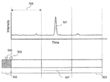
- the horizontal axis of the graph shown in FIG. 2 indicates time, and the vertical axis indicates signal intensity.
- the introduction operation 202 of the sample into one of the injection valves 104, 108, 112 and the separation column of any of the injection valves 104, 108, 112.
- the control unit 101 of the multi HPLC system 102, 106, 110 starts the analysis process from the analysis start point 204 at the same time when the sample is introduced into the analysis channel, and the data collection section 206 including the peak 205 of the separated measurement target component.
- the flow path switching valve 115 is switched so as to introduce only into the detector 116, and data collection is performed in the detector 116.
- the HPLC system 102, 106, 110 having the target component introduced into the detector 116 prepares for the next sample introduction through the step 207 of washing and equilibration of the separation columns 105, 109, 113.
- control unit 101 adjusts the data collection interval 206 to be introduced to the detector 116 so that the data collection time of the detector 116 does not overlap among the plurality of HPLC systems 102, 106, 110.
- the sample to be measured is sampled by the sample dispensing mechanism 114.
- Optimal scheduling of analysis items is realized by adjusting the waiting time until the injection valves 104, 108, 112 are switched to be introduced into the analysis channel after being introduced into the injection valves 104, 108, 112. This is an example of
- the operation flowchart shown in FIG. 3 shows that the data collection timing is heavy when the components to be measured separated by the plurality of HPLC systems 102, 106, 110 are introduced into the mass spectrometer 116 which is a detector and data are collected. It is an example of a process for adjusting the sample introduction timing to the analysis channel so that throughput performance does not decrease.
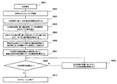
- step S302 when an analysis request S301 is received, scheduling of each analysis item is started (step S302).
- control unit 101 determines the analysis order of each analysis item according to the analysis request (step S303).
- step S304 the dispensing operation time, dispensing start time, introduction start time, analysis time, and data collection time information of each analysis item necessary for scheduling are extracted.
- step S305 Based on the information extracted in step S304, in step S305, the time (t sa ) required from the start of analysis of each analysis item to the start of data collection by the mass spectrometer 116 is calculated.
- step S306 If the calculation result in step S306 is positive, the process proceeds to step S308.
- step S306 If the calculation result in step S306 is negative, in the i-th analysis, the waiting time from the sample dispensing to the switching of the injection valve 104, 108 or 112 to introduce the sample into the analysis channel (T w ) is added (step S307).
- control unit 101 After completion of the processes of steps S306 and S307, the control unit 101 allocates data collection time to the free time of the mass spectrometer 116 according to the analysis time of the analysis item (step S308).
- step S308 After the allocation of the data collection time is completed in step S308, it is checked whether the dispensing order of the sample dispensing mechanism 114 matches the analysis order determined in step S303 (step S309).
- step S309 if the dispensing order of the sample dispensing mechanism 114 does not match the determined analysis order, that is, if the dispensing order has been changed due to the length of analysis time, Reassignment of data collection time is performed so that the analysis order matches (step S310). Then, the process returns to step S309.
- step S309 when the dispensing order of the sample dispensing mechanism 114 matches the determined analysis order, the process proceeds to step S311.
- step S311 the control unit 101 confirms whether or not the dispensing section of each analysis item is overlapping. In step S311, if duplicate analysis exists, reassignment of data collection time is executed (step S312).
- step S313 If there is no duplicate analysis in step S311, the scheduling is completed (step S313).
- step S301 after the analysis request, the scheduling work is completed through the processes of steps S302 to S311 (step S313).
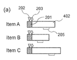
- FIG. 4A shows an outline of a time chart of each analysis of analysis items A to C having different analysis times.
- the time chart is composed of the sample dispensing operation section 201 and the analysis section 402, and the sample dispensing operation section 201 is the dispensing operation 202 of the sample to the injection valves 104, 108, 112, and the analysis of the sample.
- the analysis section 402 includes the information of the data collection section 206 of the separated components.
- the analysis area 402 of analysis item C is the longest, and the analysis area 402 of analysis item B is the shortest.
- FIG. 4B (b) is an example different from the present invention, and is a diagram for comparison with the present invention.
- (B) of FIG. 4B simply shows an example of scheduling so that the dispensing operation section 201 and the data collection section 206 of each analysis item A, B and C do not overlap.
- FIG. 4B is an example in the case of applying Example 1 of the present invention, and shows an example in which a standby section 406 is provided and optimized at the time of scheduling.
- the data collection period of the analysis item C is set, and after the dispensing operation 202 of the sample of the analysis item B to the injection valve It is necessary to set to execute the dispensing operation 202 of the sample of the analysis item C to the injection valve. Since the analysis item C has a longer analysis time than the analysis item B, data collection of the analysis item C must be started at a certain period after the data collection interval of the analysis item B ends.
- the operation of analysis item A is executed after the previous analysis item C, but the entire analysis time of analysis item A is shorter than the entire analysis time of analysis item C, and the data collection interval is Even if it starts immediately after the end of analysis item C, the dispensing operation 202 of analysis horizontal A will be after the dispensing operation 202 of analysis item C.
- the setting of execution can be performed like 1st time.
- the analysis item C in the second time has the whole analysis time longer than that of the analysis item B as in the first setting. Data collection must be started.
- time Tb is required as a whole.
- the dispensing operation 202 of the analysis item B ′ performed immediately before the analysis item C of the longest analysis time and the analysis channel of the sample A waiting section 406 is provided between the introduction 203 and the sample 203, and the introduction 203 of the sample into the analysis channel is the sample of the analysis item A while the dispensing operation 202 is kept immediately before the data collection section 206 of the analysis item A. It starts early after the dispensing operation section 201.
- the analysis time of the analysis item C is set to start early until immediately after the sample analysis operation period 201 of the analysis item B 'adjusted to start the sample dispensing operation period 201 of the analysis item C early. It can move.
- the first analysis item C can be started earlier by the time when the first analysis item C was started earlier.
- the 2nd analysis item C it can start early by providing the waiting
- the total processing time Tc in the scheduling according to the first embodiment of (c) of FIG. 4B can be shorter than the total processing time Tb in the scheduling according to (b) of FIG. 4B different from the present invention.
- the standby section 406 between the dispensing operation 202 of the analysis item B ′ and the introduction 203 of the sample, the data collection section in the mass spectrometer is shifted, and at the same time, the analysis item B is performed.
- the data acquisition intervals of the detector 116 approach each other appropriately, thereby shortening the time of the entire data acquisition interval, It is possible to implement items A, B 'and C efficiently.
- the calculation of the waiting time 406 and the scheduling such as the sample dispensing operation of the plurality of analysis items and the execution thereof are executed by the control operation of the control unit 101.
- Example 2 Next, Example 2 will be described.
- the second embodiment normalizes the analysis section of the analysis item with an integral multiple of one reference time. This is an example.
- FIG. 5 is a conceptual view of measurement data in which the analysis section of the liquid chromatogram in Example 2 is normalized
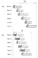
- FIG. 6 is an example of the scheduling process of each standardized analysis item analyzed by the multi HPLC mass spectrometer in Example 2.
- FIGS. 7A, 7B, and 7C are diagrams showing an example of a time chart of continuous analysis of each analysis item in which the analysis time is normalized in the second embodiment.
- the overall configuration is the same as the example shown in FIG. 1, so the illustration and detailed description will be omitted.
- Example 2 when using analysis conditions in which the analysis section is standardized, the sample is introduced into the injection valves 104, 108, and 112 by the sample dispensing mechanism 114, and then the sample is introduced into the analysis channel.
- the sample is introduced into the injection valves 104, 108, and 112 by the sample dispensing mechanism 114, and then the sample is introduced into the analysis channel.
- the sample dispensing operation section 502 including the dispensing operation 504 to the injection valves 101, 108, 112 and the introduction 505 to the analysis channel, and the standardized analysis section 503, the data
- the collection section 507 is defined in a standardized time range including the measurement target component peak 501.
- the standardized analysis interval 503 is divided at a reference time 506. In the example shown in FIG. 5, the analysis interval 503 is divided at three reference times 506.
- FIG. 6 is an operation flowchart of the second embodiment.
- the data collection timing is It is an example process for adjusting the sample introduction timing to the analysis channel so as not to overlap and to reduce the throughput performance.
- step S603 when an analysis request is received (step S601) and scheduling of each analysis item is started (step S602), the control unit 101 determines the analysis order of each analysis item according to the analysis request as the first stage of scheduling. (Step S603).
- step S604 information related to the dispensing operation section 504, the introduction start time 505, the data collection section 507, and the number of analysis cycles of each analysis item necessary for scheduling is extracted. Based on the information extracted in step S604, the number of analysis cycles of each analysis item is compared, and the difference between the number of analysis cycles of each analysis item is calculated so as to be the same as the number of cycles of the longest number of analysis. (Step S605).
- the calculated difference cycle number is added after the dispensing section as a standby cycle from the dispensing operation 504 to the sample introduction 505 to the analysis channel (step S606).
- control unit 101 After completion of the process up to step S606, the control unit 101 allocates data collection time to free time of the mass spectrometer 116 according to the execution order of analysis items and the data collection section 507 (step S607).
- step S607 the control unit 101 checks whether the dispensing operation section 502 of each analysis item is duplicated (step S608), and if there is a duplicate analysis, the data collection section (data collection time ) Reassignment of step 507) (step S609). Then, the process returns to step S608.
- the scheduling operation is ended through the process of steps S603 to S609 (step S610).
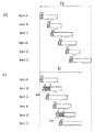
- FIG. 7A shows a schematic diagram of a time chart of each analysis standardized for analysis items A to C having different analysis times.
- the time chart shown in FIG. 7A includes a sample dispensing operation section 502 and a standardized analysis section 503, and the sample dispensing operation 504 to the injection valve, the introduction 505 of the sample to the analysis channel, and the separated
- the information of the component data collection section 507 is included.
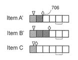
- the number of units of the standardized reference time 506 of the analysis section 503 of the analysis item C is the longest at 5, and the number of units of the standardized reference time 506 of the analysis section 503 of the analysis item B. (The number of analysis cycles) is the shortest at three. The number of units of the standardized reference time 506 of the analysis section 503 of the analysis item A is four.
- FIG. 7B is a schematic diagram in which the number of analysis cycles is adjusted in accordance with the analysis item C having the largest number of analysis cycles (the analysis interval 503 is long) for each analysis item shown in FIG. 7A.
- the analysis item A ′ and B ′ have a reference time 506 between the end of the dispensing section 502 and the start of the sample introduction 505 so that the number of analysis cycles is 5 which is the same as the number of analysis items C.
- a standby cycle 706 is set. That is, in the analysis item A ', one reference time 506 is added to form the waiting time 706, and in the analysis item B', two reference times 506 are added to form the waiting time 706.
- FIG. 7C (b) is an example different from the present invention, and is a diagram for comparison with the present invention.
- the analysis interval 503 is simply divided at the reference time 506, and the analysis items A, B and C have different analysis intervals 503, and the long / short relationship is not adjusted. Further, an example is shown in which scheduling is performed so that the dispensing operation section 502 and the data collection section 507 of each of the analysis items A, B and C do not overlap.
- one reference time 506 is obtained between the dispensing operation 504 of the analysis item A ′ and the introduction 505 of the sample into the analysis channel.
- a standby zone 706 is provided between the two dispensing times 504 of the analysis item B ′ performed immediately before the analysis item C of the longest analysis time and the introduction 505 of the sample into the analysis flow path.
- the waiting interval is between the dispensing operation 504 of the analysis item B ′ performed immediately before the analysis item C of the longest analysis time and the introduction 505 of the sample to the analysis channel. 706 is provided, and the introduction 505 of the sample into the analysis channel remains immediately before the data collection section 507 of the analysis item A ′, and the dispensing operation 504 is after the sample dispensing operation section 502 of the analysis item A ′. It has started early.
- the analysis period C of the analysis item C is started so that the sample dispensing operation period 502 of the analysis item C is started early until immediately after the sample analysis operation period 502 of the analysis item B ′ adjusted to start early. Can move.
- the first analysis item C can be started earlier by the time when the first analysis item C was started earlier.
- the 2nd analysis item C it can start early by providing the waiting
- the total processing time Te in the scheduling according to the second embodiment of (c) of FIG. 7C can be shorter than the total processing time Td in the scheduling according to (b) of FIG. 7C different from the present invention.
- the same effect as the first embodiment can be obtained.
- the analysis intervals 503 of the plurality of analysis items A, B, and C are divided at the reference time 506, the waiting time 706 is added, and the analysis intervals 503 are equal to one another. Since scheduling is performed on the assumption that 'C', scheduling can be easily performed.
- Example 3 Next, Example 3 will be described.
- Example 3 is a multi-HPLC mass spectrometer in which a plurality of HPLC systems 102, 106, 110 in the present invention are connected to one mass spectrometer which is a detector 116 via a flow path switching valve 115. It is an example applied to the example which performs a gradient elution method as a sample separation technique and carries out component separation.
- Example 3 instead of adjusting the introduction timing of the measurement sample into the analysis channel shown in Example 1 and Example 2, after the sample to be measured is introduced into the analysis channel, gradient elution is started. It is an example which realizes scheduling of an optimal analysis item by adjusting time to until.
- the affinity between the column as the stationary phase and the solvent as the mobile phase is changed by changing the concentration ratio between the solvent for immobilizing the sample to be measured on the column and the solvent to be separated from the column.
- the component separation is realized by adjustment.
- gradient elution is started with the start of separation, but when the solvent for fixing the sample is continuously sent, the component to be measured does not separate / elute from the column.
- the elution time can be adjusted by providing a gradient waiting time in which the solvent used at the time of sample fixation is continued between the start of analysis and the start of gradient elution.
- the waiting time required for the adjustment of scheduling shown in Example 3 is the same process as the process shown in FIG. 3 of Example 1 and FIG. Calculated as the waiting time of
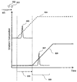
- FIG. 8 is a diagram showing the outline of the change of the gradient curve by the change of the mixing ratio of the solvent and the addition of the waiting time in the analysis performed using the gradient elution method in Example 3.
- the analysis process according to the third embodiment is a sample dispensing process (sample dispensing section) 801 having sample dispensing 802 to the injection valve 104, 108, 112 and introduction 803 to the analysis channel by the sample introduction mechanism. And a sample analysis process started after sample dispensing, and gradient elution is started at any time after the start of analysis.
- the start time of the gradient elution is reset, and from the gradient curve 804 (shown by a broken line) in the prior art to the gradient curve 806 after reset (shown by a solid line) It becomes possible to change, and it is changed (adjusted) from the elution time 805 of the sample before resetting to the adjusted elution time 807.
- control unit 101 can execute scheduling according to the free time of the mass spectrometer for a plurality of analysis items. it can.
- the elution time can be adjusted to shorten not only the analysis processing time, but also the waiting time can be added to further shorten the analysis processing time.
- Example 3 the same effects as those of Example 1 can be obtained by utilizing the characteristics of the gradient elution method, and the effects as described above can be obtained.
Landscapes
- Physics & Mathematics (AREA)
- Health & Medical Sciences (AREA)
- Life Sciences & Earth Sciences (AREA)
- Chemical & Material Sciences (AREA)
- Analytical Chemistry (AREA)
- Biochemistry (AREA)
- General Health & Medical Sciences (AREA)
- General Physics & Mathematics (AREA)
- Immunology (AREA)
- Pathology (AREA)
- Other Investigation Or Analysis Of Materials By Electrical Means (AREA)
Abstract
異なる分析時間または試料分離時間をもつ分析項目を複数サイクル繰り返すような分析を行う場合であっても全体の稼働効率を向上可能な複数のクロマトグラフを有する分析装置が実現される。分析項目Cの前の分析項目B'の分注動作202と試料分析流路導入203の間に待機区間406を設け試料分析流路導入203は分析項目Aのデータ収集区間206の前として分注動作202を分析項目Aの試料分注動作区間201より後の早期に開始する。分析項目Cの試料分注動作区間201を早期に開始し、分析項目B'の試料分析動作区間201の直後まで分析項目Cの分析時間を移動できる。第2回目の分析項目Aは第1回目の分析項目Cの早期開始時間分だけ早期開始できる。実施例1による全体処理時間Tcは本発明とは異なる例の全体処理時間Tbより短縮できる。
Description
本発明は、複数のクロマトグラフと検出器を組み合わせたクロマトグラフを有する分析装置に関する。
クロマトグラフは、試料を分離するカラムに送られる移動相に、測定対象となる成分を含む試料を加え、固定相で試料の成分分離を行い、異なる時間成分に分離された各成分を検出器にて検出し、試料の成分を特定する分析装置である。
例えば、移動相に溶媒を用いた高性能液体クロマトグラフ(HPLC)では、送液装置が溶媒を高圧送液し、送液装置の下流に設置された試料注入部から分析流路に注入された試料が固定相を充填した分離カラムにて各成分に分離される。そして、紫外・可視吸光光度計、蛍光光度計、質量分析計などの検出器を用いて検出し、成分が特定される。
この場合、検出器は分析目的や試料に応じて適宜選択される。
測定対象の質量情報を取得する質量分析計とクロマトグラフを組み合わせたクロマトグラフ質量分析装置は、クロマトグラフで測定試料から時間成分に分離された各成分を質量分析計に導入し質量情報を取得する分析装置である。このクロマトグラフ質量分析装置は、定性分析や定量分析を行うために広く用いられている。
近年では、生体試料中の薬剤成分や代謝物、環境試料中の残留物を定量測定するためにクロマトグラフ質量分析装置を使用する機会が増えている。
このようなクロマトグラフ質量分析装置は特定の分析条件を用いた連続分析用として使用されることが多く、分析装置として高い処理能力(スループット性能)が望まれる。
しかしながら、従来のクロマトグラフ質量分析装置では、質量分析計のデータ収集時間に対しクロマトグラフにおける測定対象を分離する時間の方が長いため、質量分析計がデータを取得していない非稼動状態が多くスループット性能が低いという課題があった。
そこで、特許文献1では、上記課題に対し、複数のクロマトグラフを1台の質量分析計に接続させ、各クロマトグラフで分離された測定対象試料を連続して質量分析計に導入することで質量分析計の稼働率を改善し、スループット性能を向上させたシステムが提案されている。
このような複数のクロマトグラフを1台の質量分析計に接続したマルチクロマトグラム質量分析装置では、クロマトグラムで分離した試料の各成分を効率的に質量分析計へ導入することが重要になる。
クロマトグラフ、例えばHPLCにおいて、その分析工程は、カラムの平衡化、試料注入、試料の成分溶出、カラム洗浄で構成されるが、質量分析計のデータ収集工程は、試料の成分溶出工程の一定区間のみで実施される。
そのため、複数のHPLCを並列に接続したマルチHPLC質量分析装置では、質量分析計における分離された試料のデータ収集工程が重ならないように各HPLCの分析開始タイミングをスケジューリングすることが重要になる。
しかしながら、HPLCを用いた分析法では、測定対象物質の優れた分離性能を得るために、カラムの種類や分析流量、移動相組成比の変化量(グラジエント変化量)、カラムの平衡化時間等の分析条件を分析種毎に最適化することが一般的である。このため、同一試料の分析では同じ分析条件で分析することが可能だが、測定対象が異なる場合では、分析条件だけではなく試料分離時間や全体の分析時間についても一様になることはない。
よって、異なる分析時間または試料分離時間をもつ分析項目を複数サイクル繰り返すような分析を行う場合、単に、試料の質量分析計への導入タイミングが重ならないようにスケジューリングしただけでは、質量分析計の稼働率改善は期待できても分析装置の全稼働時間が長くなり、分析項目ごとのスループットが悪化するという問題が発生する場合がある。
また、前述のHPLCを用いた分析法の特徴から、分離成分の溶出タイミングを調整するために、流量やグラジエント変化量などの分析条件を変更することは、分離性能が悪化する原因となる可能性があるため困難である。
本発明の目的は、異なる分析時間または試料分離時間をもつ分析項目を複数サイクル繰り返すような分析を行う場合であっても、全体の稼働効率を向上可能な複数のクロマトグラフを有する分析装置を実現することである。
上記目的を達成するため、本発明は次のように構成される。
複数のクロマトグラフを有する分析装置において、移動相を分析流路に送出する送出装置と、この送出装置に接続され、試料を分析流路に導入する注入バルブと、この注入バルブの下流に接続され、上記試料を各成分に分離する分離カラムとを有するクロマトグラフを複数備えるマルチクロマトグラフ装置と、上記マルチクロマトグラフの上記注入バルブに試料を分注する少なくとも一つの試料分注機構と、試料を分析する検出器と、上記マルチクロマトグラフの上記分離カラムに接続され、上記複数のクロマトグラフ装置のいずれかの上記分離カラムにより分離された試料を、上記分析流路を介して上記検出器に導入する流路切換バルブと、上記マルチクロマトグラフ、上記試料分注機構、上記流路切換バルブ及び上記検出器の動作を制御する制御部と、を備え、上記制御部は、上記複数のクロマトグラフのそれぞれの試料分析項目における上記検出器のデータ収集区間が、互いに重複せず、かつ、上記データ収集区間が互いに接近するように、上記試料の上記分析流路への導入動作を制御する。
また、本発明は次のように構成される。
複数のクロマトグラフを有する分析装置において、移動相を分析流路に送出する送液装置と、この送出装置に接続され、液体試料を分析流路に導入する注入バルブと、この注入バルブの下流に接続され、上記試料を各成分に分離する分離カラムとを有する液体クロマトグラフを複数備えるマルチクロマトグラフ装置と、上記マルチクロマトグラフの上記注入バルブに試料を分注する少なくとも一つの試料分注機構と、液体試料を分析する検出器と、上記マルチクロマトグラフの上記分離カラムに接続され、上記複数のクロマトグラフ装置のいずれかの上記分離カラムにより分離された試料を上記検出器に導入する流路切換バルブと、上記マルチクロマトグラフ、上記試料分注機構、上記流路切換バルブ及び上記検出器の動作を制御する制御部と、を備え、上記試料の分析を行う分析区間は、基準時間の整数倍で分割され規格化されている。
本発明によれば、異なる分析時間または試料分離時間をもつ分析項目を複数サイクル繰り返すような分析を行う場合であっても、全体の稼働効率を向上可能な複数のクロマトグラフを有する分析装置を実現することができる。
以下、本発明の実施形態について添付図面を参照して説明する。
なお、本発明は以下に説明する実施例に限定されるものではなく、技術思想の範囲において応用が可能である。
また、本発明の実施例ではクロマトグラフとしてHPLCを用いて記載しているが、その他のクロマトグラフ、例えばガスクロマトグラフ(GC)を用いたGC質量分析装置についても試料導入タイミングを調整することで本発明は適用可能である。
また、HPLCの検出器として質量分析計を使用したHPLC質量分析装置について記載しているが、質量分析計以外の検出器、たとえば可視・紫外吸光度検出器やフォトダイオードアレイ検出器、蛍光検出器等においても本発明は適用可能である。
(実施例1)
図1は、本発明の実施例1が適用されるマルチHPLC質量分析装置の概念図であり、図2は液体クロマトグラム装置の測定データの概念図である。そして、図3は、実施例1におけるマルチHPLC質量分析装置で分析される項目のスケジューリングプロセス例を示す動作フローチャートであり、図4は実施例1における各分析項目の連続分析のタイムチャート及び実施例1が適用されない場合の各分析項目の連続分析のタイムチャートを示す図である。
図1は、本発明の実施例1が適用されるマルチHPLC質量分析装置の概念図であり、図2は液体クロマトグラム装置の測定データの概念図である。そして、図3は、実施例1におけるマルチHPLC質量分析装置で分析される項目のスケジューリングプロセス例を示す動作フローチャートであり、図4は実施例1における各分析項目の連続分析のタイムチャート及び実施例1が適用されない場合の各分析項目の連続分析のタイムチャートを示す図である。
図1に示すように、マルチHPLC分析装置は、HPLCシステム(クロマトグラフ)102と、HPLCシステム106と、HPLCシステム110と、HPLCシステム102に試料を分注する試料分注機構(Sampler)114と、流路切り換えバルブ115と、検出器(Detector)116と、HPLCシステム102、試料分注機構114、流路切換バルブ115及び検出器116を制御する制御部(Contoroler)101とを備える。
HPLCシステム102は、移動相となる溶媒を分析流路に高圧送液する送液装置(Pump、ポンプ(送出装置))103と、送液装置103に接続され試料を分析流路へ導入する注入バルブ104と、注入バルブ104の下流に接続され、注入バルブ104から分析流路を介して試料が供給され、供給された試料を各成分に分離する分離カラム(Column)105とを有する。
また、HPLCシステム106は、HPLCシステム102と同様な構成となっており、移動相となる溶媒を高圧送液する送液装置(Pump、ポンプ)107と、送液装置107に接続され、試料を分析流路へ導入する注入バルブ108と、注入バルブ108の下流に接続され、試料を各成分に分離する分離カラム(Column)109とを有する。
また、HPLCシステム110も、HPLCシステム102と同様な構成となっており、移動相となる溶媒を高圧送液する送液装置(Pump、ポンプ)111と、送液装置111と接続され、試料を分析流路へ導入する注入バルブ112と、注入バルブ112の下流に接続され、試料を各成分に分離する分離カラム(Column)113とを有する。
HPLCシステム102の分離カラム105、HPLCシステム106の分離カラム109及びHPLCシステム110の分離カラム113は、流路切換バルブ115を介して1つの検出器(質量分析装置)116に並列接続されている。
試料分注機構(サンプラー)114はHPLCシステム102、106、110の分析流路に接続した注入バルブ104、108、112へ試料を分注する。流路切換バルブ115により試料が検出器116に導入される。
図1には、1つの試料分注機構114を示したが、試料分注機構114は複数であってもよい。
また、図1には、1つの流路切換バルブ115を示したが、流路切換バルブ115は、複数であってもよい。
HPLCシステム102、106及び110を備える装置をマルチクロマトグラフ装置とする。
図2に示したグラフの横軸は時間を示し、縦軸は信号強度を示している。図2において、試料分注装置114の試料分注動作区間201は、試料の注入バルブ104、108、112のいずれかへの導入動作202と、注入バルブ104、108、112のいずれかが分離カラム105、109、113のいずれかへの分析流路へ接続するために切り換え動作203がある。
マルチHPLCシステム102、106、110の制御部101は試料が分析流路に導入されたと同時に、分析開始点204から分析工程を開始し、分離された測定対象成分のピーク205を含むデータ収集区間206のみを検出器116に導入するように流路切換バルブ115を切り換えて、検出器116にてデータ収集を実施する。
このとき、移動相の濃度比を変更しながら成分を分離するグラジエント溶出法が用いられる場合、試料が導入された後にグラジエント溶出が開始されるのが一般的である。
図2において、目的成分を検出器116に導入したHPLCシステム102、106、110は、分離カラム105、109、113の洗浄および平衡化の工程207を経て、次の試料導入に備える。
マルチHPLCシステムにおいて、制御部101はデータ収集区間206が検出器116に導入され、検出器116にてデータ収集される時間が複数のHPLCシステム102、106、110間で重ならないように調整する。
実施例1は、複数のHPLCシステム102、106、110が流路切換バルブ115を介して1つの質量分析計116に接続されたマルチHPLC質量分析装置において、測定対象試料が試料分注機構114により注入バルブ104、108、112に導入されてから試料を分析流路に導入させるために注入バルブ104、108、112が切り換わるまでの待機時間を調整することで、最適な分析項目のスケジューリングを実現する例である。
図3に示した動作フローチャートは、複数のHPLCシステム102、106、110で分離された測定対象成分が検出器である質量分析装置116に導入されてデータ収集される際に、データ収集タイミングが重ならず、かつ、スループット性能が低減しないように、分析流路への試料導入タイミングを調整するためのプロセス例である。
図3において、マルチHPLC質量分析装置では、分析要求S301が入ると各分析項目のスケジューリングを開始する(ステップS302)。
スケジューリング第1段階として、制御部101は分析要求に従い各分析項目の分析順番を決定する(ステップS303)。
次に、ステップS304では、スケジューリングに必要な各分析項目の分注動作時間、分注開始時間、導入開始時間、分析時間、データ収集時間情報が抽出される。
ステップS304にて抽出された情報をもとにステップS305において、各分析項目の分析開始から質量分析計116によるデータ収集開始までに要する時間(tsa)を算出する。
i番目の時間tsa(i)がi-1番目tsa(i-1)の時間よりも小さいとき、i番目のデータ収集開始時にひとつ前のi-1番目のデータ収集は終わっていない状態が発生する可能性があるため、ステップS306では試料を分析流路へ導入するタイミングを調整するために必要なi番目のtsa(i)とi-1番目tsa(i-1)の差分を算出する。
ステップS306での算出結果が正であった場合は、ステップS308に進む。
ステップS306での算出結果が負であった場合には、i番目の分析において、試料分注後から注入バルブ104、108または112を切り換えて試料を分析流路に導入するまでの間に待機時間(tw)を追加する(ステップS307)。
ステップS306、S307のプロセスが終了後に、制御部101は分析項目の分析時間に応じて、質量分析計116の空き時間にデータ収集時間の割り当てを実行する(ステップS308)。
質量分析計116のデータ収集時間を割り当てる際は、質量分析計116の空き時間が極力少なくなるように割り当てるのが望ましい。
ステップS308にて、データ収集時間の割り当てが終了した後、ステップS303にて決定した分析順番に対して試料分注機構114の分注順番が一致しているか否かを確認する(ステップS309)。
ステップS309において、決定した分析順番に対して試料分注機構114の分注順番が一致していない場合、つまり、分析時間の長さにより分注順番が変わってしまった場合は、分注順番と分析順番が一致するようにデータ収集時間の再割り当てを実行する(ステップS310)。そして、ステップS309に戻る。
ステップS309において、決定した分析順番に対して試料分注機構114の分注順番が一致している場合は、ステップS311に進む。
ステップS311において、制御部101は各分析項目の分注区間が重複していないかを確認する。ステップS311において、重複する分析が存在する場合は、データ収集時間の再割り当てを実行する(ステップS312)。
ステップS311において、重複する分析が存在しない場合は、スケジューリング終了となる(ステップS313)。
上述したように、ステップS301において、分析要求後、ステップS302からS311のプロセスを経てスケジューリング作業が終了される(ステップS313)。
図4Aは、異なる分析時間をもつ分析項目A~Cの各分析のタイムチャートの概略を示している。
図4Aにおいて、タイムチャートは、試料分注動作区間201と分析区間402とで構成され、試料分注動作区間201は、試料の注入バルブ104、108、112への分注動作202、試料の分析流路への導入203を含み、分析区間402は、分離した成分のデータ収集区間206の情報を含んでいる。
そして、図4Aに示した例では、分析項目Cの分析区間402が最も長く、分析項目Bの分析区間402が最も短い。
図4Bの(b)は、本発明とは異なる例であり、本発明との比較のための図である。図4Bの(b)は、単に、各分析項目A、B及びCの分注動作区間201とデータ収集区間206が重複しないようにスケジューリングした例を示している。
これに対して、図4Bの(c)は、本発明の実施例1を適用した場合の例であり、スケジューリングする際に待機区間406を設けて最適化した例を示している。
図4Bの(b)に示した例において、第1回目における分析項目A(itemA)に続く分析項目Bにおいては、先の分析項目Aにおけるデータ収集区間の次に分析項目Bのデータ収集区間を実行しなければならない関係上、図示のようなスケジュールとなる。
次に、分析項目Cにおいては、先の分析項目Bのデータ収集区間の後に、分析項目Cのデータ収集区間を設定し、かつ、分析項目Bの試料の注入バルブへの分注動作202の後に、分析項目Cの試料の注入バルブへの分注動作202を実行するように設定する必要がある。分析項目Cは、分析項目Bより全体の分析時間が長いことから、分析項目Bのデータ取集区間終了後、ある期間をおいて分析項目Cのデータ収取を開始しなければならない。
第2回目における、分析項目Aの動作は、前回の分析項目Cの次に実行されるが、分析項目Aの全体の分析時間は、分析項目Cの全体の分析時間より短く、データ収集区間を分析項目Cの終了直後に開始しても、分析横目Aの分注動作202は、分析項目Cの分注動作202の後となる。第2回目における分析項目Bについては、第1回目と同様にして、実行の設定を行うことができる。
第2回目における分析項目Cは、第1回目の設定と同様に、分析項目Bより全体の分析時間が長いことから、分析項目Bのデータ取集区間終了後、ある期間をおいて分析項目Cのデータ収集を開始しなければならない。
この結果、分析項目BとCとにおける全体の分析時間の長短の関係から分析項目Bのデータ収取区間と、分析項目Cのデータ収集区間との間に、時間を置かねばならず、2回繰り返して分析を行うスケジュールでは、全体として時間Tbが必要である。
これに対して、図4Bの(c)に示した実施例1におけるスケジューリングにおいては、最も長い分析時間の分析項目Cの直前に実行する分析項目B’の分注動作202と試料の分析流路への導入203との間に待機区間406を設け、試料の分析流路への導入203は、分析項目Aのデータ収集区間206の直前としたままで、分注動作202を分析項目Aの試料分注動作区間201より後の早期に開始している。
これによって、分析項目Cの試料分注動作区間201を、早期に開始するように調整した分析項目B’の試料分析動作区間201の直後まで、早期に開始するように分析項目Cの分析時間を移動することができる。
そして、第2回目の分析項目Aについては、第1回目の分析項目Cが早期に開始された時間分だけ早期に開始することができる。第2回目の分析項目Cについては、第2回目の分析項目B’に第1回目と同様に待機区間406を設けることにより、早期に開始することができる。
よって、図4Bの(c)の実施例1によるスケジューリングにおける全体処理時間Tcは、本発明とは異なる図4Bの(b)によるスケジューリングにおける全体処理時間Tbより短縮することが可能となる。
つまり、実施例1によれば、分析項目B’の分注動作202から試料を導入203の間に待機区間406を設けることで、質量分析計でのデータ収集区間をずらすと同時に、分析項目B’の試料分注区間の終了と同時に分析項目Cの分注を開始することで、検出器116のデータ収集区間が適切に互いに接近させることにより、全体のデータ収集区間の時間を短縮し、分析項目A、B’、Cを効率的に実施することを可能にしている。
待機時間406の算出及び複数の分析項目の試料分注動作等のスケジューリング及びその実行は、制御部101の制御動作によって実行される。
以上のように、本発明の実施例1によれば、異なる分析時間または試料分離時間をもつ分析項目を複数サイクル繰り返すような分析を行う場合であっても、全体の稼働効率を向上可能な複数のクロマトグラフを有する分析装置を実現することができる。
(実施例2)
次に、実施例2について説明する。
次に、実施例2について説明する。
実施例2は、複数のHPLCシステムが流路切換バルブを介して1つの質量分析計に接続されたマルチHPLC質量分析装置において、分析項目の分析区間があるひとつの基準時間の整数倍で規格化されている例である。
実施例2について、図5~図7A、図7B、図7Cを参照して説明する。図5は実施例2における液体クロマトグラムの分析区間を規格化した測定データ概念図、図6は実施例2におけるマルチHPLC質量分析装置で分析される規格化された各分析項目のスケジューリングプロセス例を示す図、図7A、図7B、図7Cは実施例2における分析時間が規格化された各分析項目の連続分析のタイムチャート例を示す図である。全体構成は、図1に示した例と同様となっているので、図示及び詳細な説明は省略する。
また、実施例2は、分析区間が規格化された分析条件を用いる場合、試料が試料分注機構114により注入バルブ104、108、112に導入されてから試料を分析流路に導入させるために注入バルブ104、108、112が切り換えるまでのサイクル数を調整することで、より簡便なプロセスで最適な分析項目のスケジューリングを実現することが可能になる例である。
図5において、注入バルブ101、108、112への分注動作504と分析流路への導入505とを含む試料分注動作区間502と規格化された分析区間503とで構成されており、データ収集区間507は測定対象成分ピーク501を含む規格化された時間範囲で定義される。規格化された分析区間503は、基準時間506で分割されている。図5に示した例では、分析区間503は、3つの基準時間506で分割されている。
図6は、実施例2の動作フローチャートである。図6に示した例は、規格化された分析条件を用いて、マルチHPLCシステムで分離された測定対象成分を検出器である質量分析装置に導入しデータ収集される際に、データ収集タイミングが重ならず、かつ、スループット性能が低減しないように、分析流路への試料導入タイミングを調整するためのプロセス例である。
図6において、分析要求が入り(ステップS601)、各分析項目のスケジューリングが開始されると(ステップS602)、制御部101はスケジューリングの第1段階として分析要求に従い各分析項目の分析順番を決定する(ステップS603)。
ステップS604では、スケジューリングに必要な各分析項目の分注動作区間504、導入開始時間505、データ収集区間507、分析サイクル数に関わる情報が抽出される。ステップS604にて抽出された情報をもとに各分析項目の分析サイクル数を比較し、最も長い分析数のサイクル数と同じサイクル数になるように各分析項目の分析サイクル数の差分を算出する(ステップS605)。
算出された差分サイクル数を、分注動作504から分析流路への試料導入505までの待機サイクルとして分注区間後に追加する(ステップS606)。
ステップS606までのプロセス終了後に、制御部101は分析項目の実施順番とデータ収集区間507に応じて、質量分析計116の空き時間にデータ収集時間の割り当てを実行する(ステップS607)。
質量分析計116のデータ収集区間507を割り当てる際は、質量分析計116の空き時間が極力少なくなるように割り当てるのが望ましい。
ステップS607のプロセス終了後に、制御部101は各分析項目の分注動作区間502が重複していないかを確認し(ステップS608)、重複する分析が存在する場合は、データ収集区間(データ収集時間)507の再割り当てを実行する(ステップS609)。そして、ステップS608に戻る。
ステップS603~S609のプロセスを経てスケジューリング作業を終了させる(ステップS610)。
図7Aは、異なる分析時間をもつ分析項目A~Cについて規格化された各分析のタイムチャートの概略図を示している。
図7Aに示したタイムチャートは、試料分注動作区間502と規格化された分析区間503で構成され、試料の注入バルブへの分注動作504、試料の分析流路への導入505、分離した成分のデータ収集区間507の情報を含んでいる。
図7Aに示した例では、分析項目Cの分析区間503の規格化された基準時間506の単位数は5で最も長く、分析項目Bの分析区間503の規格化された基準時間506の単位数(分析サイクル数)は3で最も短い。分析項目Aの分析区間503の規格化された基準時間506の単位数は4である。
図7Bは、図7Aで示した各分析項目について、最も分析サイクル数が多い(分析区間503が長い)分析項目Cに合わせて分析サイクル数を調整した概略図である。
ここで、分析項目A’とB’は、分析サイクル数が分析項目Cと同じサイクル数である5となるように、分注区間502の終了後に試料導入開始505までの間に基準時間506が追加され、待機サイクル706が設定されている。つまり、分析項目A’は、一つの基準時間506が追加されて待機時間706が形成され、分析項目B’は、二つの基準時間506が追加されて待機時間706が形成されている。
図7Cの(b)は、本発明とは異なる例であり、本発明との比較のための図である。図7Cの(b)は、分析区間503を基準時間506で単に分割し、分析項目A、B及びCは、分析区間503が互いに異なっており、長短関係は調整されていない。そして、各分析項目A、B及びCの分注動作区間502とデータ収集区間507とが重複しないようにスケジューリングした例を示している。
これに対して、図7Cの(c)に示した実施例2におけるスケジューリングにおいては、分析項目A’の分注動作504と試料の分析流路への導入505との間に一つの基準時間506からなる待機区間706を設け、最も長い分析時間の分析項目Cの直前に実行する分析項目B’の分注動作504と試料の分析流路への導入505との間に二つの基準時間506からなる待機区間706を設けている。
図7Cの(c)に示した例では、最も長い分析時間の分析項目Cの直前に実行する分析項目B’の分注動作504と試料の分析流路への導入505との間に待機区間706を設け、試料の分析流路への導入505は、分析項目A’のデータ収集区間507の直前としたままで、分注動作504を分析項目A’の試料分注動作区間502より後の早期に開始している。
これによって、分析項目Cの試料分注動作区間502を、早期に開始するように調整した分析項目B’の試料分析動作区間502の直後まで、早期に開始するように分析項目Cの分析区間503を移動することができる。
そして、第2回目の分析項目A’については、第1回目の分析項目Cが早期に開始された時間分だけ早期に開始することができる。第2回目の分析項目Cについては、第2回目の分析項目B’に第1回目と同様に待機区間706を設けることにより、早期に開始することができる。
よって、図7Cの(c)の実施例2によるスケジューリングにおける全体処理時間Teは、本発明とは異なる図7Cの(b)によるスケジューリングにおける全体処理時間Tdより短縮することが可能となる。
実施例2においても、実施例1と同様な効果を得ることができる。実施例2においては、複数の分析項目A、B、Cの分析区間503を基準時間506で分割し、待機時間706を追加して、分析区間503が互いに等しい、複数の分析項目A’、B’、Cとした上で、スケジューリングを行っているため、スケジューリングを容易に実行することができるという効果がある。
(実施例3)
次に、実施例3について説明する。
次に、実施例3について説明する。
実施例3は、本発明における複数のHPLCシステム102、106、110が流路切換バルブ115を介して、検出器116である1つの質量分析計に接続されたマルチHPLC質量分析装置において、測定対象試料を分離手法としてグラジエント溶出法を実行して成分分離する例に適用した例である。
実施例3においては、実施例1及び実施例2で示した測定試料の分析流路への導入タイミングを調整する代わりに、測定対象試料を分析流路に導入されてから、グラジエント溶出を開始するまでの時間を調整することで、最適な分析項目のスケジューリングを実現する例である。
グラジエント溶出法では、測定対象試料をカラムに固定化させる溶媒と、カラムから分離させる溶媒との濃度比を変化させることで、固定相であるカラムと移動相である溶媒との間の親和性を調整することで成分分離を実現させる。
一般的に、グラジエント溶出法では分離開始と共にグラジエント溶出を開始するが、試料を固定する溶媒を送液し続けるとカラムから測定対象成分が分離・溶出しない。
この特性を利用し、分析開始からグラジエント溶出開始の間に試料固定時に使用した溶媒の送液を続けるグラジエント待機時間を設けることで溶出時間を調整することができる。
実施例3で示すスケジューリングの調整に必要な待機時間は、実施例1の図3及び実施例2の図6で示したプロセスと同様のプロセスで、試料導入までの待機時間ではなくグラジエント溶出開始までの待機時間として算出される。
図8は、実施例3におけるグラジエント溶出法を用いて実施した分析における溶媒の混合比率の変化と待機時間の追加によるグラジエントカーブの変更概略を示す図である。
図8において、実施例3による分析プロセスは、試料導入機構による注入バルブ104、108、112への試料分注802および分析流路への導入803を有する試料分注プロセス(試料分注区間)801と、試料分注後に開始される試料分析プロセスとで構成され、グラジエント溶出は分析開始後の任意の時間から開始される。
分析区間に算出された待機時間808を追加することで、グラジエント溶出の開始時間を再設定し、従来技術におけるグラジエントカーブ804(破線で示す)から再設定後のグラジエントカーブ806(実線で示す)まで変更することが可能になり、再設定前の試料の溶出時間805から、調整された溶出時間807まで変更(調整)される。
これにより、質量分析計116におけるデータ収集区間809を任意の時間に設定させることが可能になり、制御部101は、複数の分析項目について質量分析計の空き時間に合わせたスケジューリングを実行することができる。
また、実施例1または実施例2と同様に、複数の分析項目に対する待機時間を追加し、スケジューリングを行うこともできる。つまり、上述のように溶出時間を調整して、分析処理時間を短縮するのみならず、待機時間を追加して、さらに、分析処理時間を短縮することができる。
実施例3においても、グラジエント溶出方法の特性を利用し、実施例1と同様な効果を得ることができる他、上述のような効果を得ることができる。
101・・・制御部、 102、 106、 110・・・HPLCシステム、 103、 107、 111・・・送液装置(ポンプ)、 104、 108、 112・・・注入バルブ、 105、 109、 113・・・分離カラム、 114・・・試料分注機構(サンプラー)、 115・・・流路切換バルブ、 116・・・検出器、 201、 502、 801・・・試料分注動作区間、 202、 504、 802・・・注入バルブへの分注動作、 203、 505、 803・・・分析流路への導入、 204・・・分析開始点、 206、 507、 809・・・データ収集区間、 207・・・カラムの洗浄および平衡化工程、 402、 503・・・分析区間、 406、 706、 808・・・待機区間、 506・・・基準時間、 806・・・グラジエントカーブ、 807・・・試料の溶出時間
Claims (7)
- 移動相を分析流路に送出する送出装置と、この送出装置に接続され、試料を分析流路に導入する注入バルブと、この注入バルブの下流に接続され、上記試料を各成分に分離する分離カラムとを有するクロマトグラフを複数備えるマルチクロマトグラフ装置と、
上記マルチクロマトグラフの上記注入バルブに試料を分注する少なくとも一つの試料分注機構と、
試料を分析する検出器と、
上記マルチクロマトグラフの上記分離カラムに接続され、上記複数のクロマトグラフ装置のいずれかの上記分離カラムにより分離された試料を、上記分析流路を介して上記検出器に導入する流路切換バルブと、
上記マルチクロマトグラフ、上記試料分注機構、上記流路切換バルブ及び上記検出器の動作を制御する制御部と、
を備え、上記制御部は、上記複数のクロマトグラフのそれぞれの試料分析項目における上記検出器のデータ収集区間が、互いに重複せず、かつ、上記データ収集区間が互いに接近するように、上記試料の上記分析流路への導入動作を制御することを特徴とする複数のクロマトグラフを有する分析装置。 - 請求項1に記載の数のクロマトグラフを有する分析装置において、
上記送出装置は液体を送出する送液装置であり、上記試料は液体であり、上記クロマトグラフは液体クロマトグラフであって、上記制御部は、上記試料の注入バルブへの分注動作と上記流路切換えバルブによる上記検知器への試料の導入動作との間に待機時間を追加して、上記試料の上記分析流路への導入動作を制御することを特徴とする複数のクロマトグラフを有する分析装置。 - 請求項1に記載の数のクロマトグラフを有する分析装置において、
上記複数のクロマトグラフは、グラジエント溶出法により上記分離カラムにて試料分離させるグラジエント分析を実行し、上記制御部は、上記グラジエント溶出法による試料分離時間を調整して、上記複数のクロマトグラフのそれぞれの試料分析項目における上記検出器のデータ収集区間が、互いに重複せず、かつ、上記データ収集区間が互いに接近するように、上記試料の上記分析流路への導入動作を制御することを特徴とする複数のクロマトグラフを有する分析装置。 - 請求項3に記載の複数のクロマトグラフを有する分析装置において、
上記制御部は、上記グラジエント溶出法による試料分離時間を調整するとともに、上記試料の注入バルブへの分注動作と上記流路切換えバルブによる上記検知器への試料の導入動作との間に待機時間を追加して、上記試料の上記分析流路への導入動作を制御することを特徴とする複数のクロマトグラフを有する分析装置。 - 移動相を分析流路に送出する送液装置と、この送出装置に接続され、液体試料を分析流路に導入する注入バルブと、この注入バルブの下流に接続され、上記試料を各成分に分離する分離カラムとを有する液体クロマトグラフを複数備えるマルチクロマトグラフ装置と、
上記マルチクロマトグラフの上記注入バルブに試料を分注する少なくとも一つの試料分注機構と、
液体試料を分析する検出器と、
上記マルチクロマトグラフの上記分離カラムに接続され、上記複数のクロマトグラフ装置のいずれかの上記分離カラムにより分離された試料を、分析流路を介して上記検出器に導入する流路切換バルブと、
上記マルチクロマトグラフ、上記試料分注機構、上記流路切換バルブ及び上記検出器の動作を制御する制御部と、
を備え、上記試料の分析を行う分析区間は、基準時間の整数倍で分割され規格化されていることを特徴とする複数のクロマトグラフを有する分析装置。 - 請求項5に記載の数のクロマトグラフを有する分析装置において、
上記複数のクロマトグラフは、グラジエント溶出法により上記分離カラムにて試料分離させるグラジエント分析を実行し、上記制御部は、上記グラジエント溶出法による試料分離時間を調整して、上記複数のクロマトグラフのそれぞれの試料分析項目における上記検出器のデータ収集区間が、互いに重複せず、かつ、上記データ収集区間が互いに接近するように、上記試料の上記分析流路への導入動作を制御することを特徴とする複数のクロマトグラフを有する分析装置。 - 請求項5に記載の複数のクロマトグラフを有する分析装置において、
上記制御部は、上記複数のクロマトグラフのそれぞれの試料分析項目における上記検出器のデータ収集区間が、互いに重複せず、かつ、上記データ収集区間が互いに接近するように、上記注入バルブと上記流路切換えバルブの動作に上記基準時間を追加して、上記試料の上記分析流路への導入動作を制御することを特徴とする複数のクロマトグラフを有する分析装置。
Priority Applications (4)
| Application Number | Priority Date | Filing Date | Title |
|---|---|---|---|
| EP18899125.1A EP3739333A4 (en) | 2018-01-11 | 2018-11-30 | ANALYSIS EQUIPMENT HAVING A PLURALITY OF CHROMATOGRAPHS |
| JP2019564333A JP6989622B2 (ja) | 2018-01-11 | 2018-11-30 | 複数のクロマトグラフを有する分析装置 |
| CN201880091169.9A CN111868517B (zh) | 2018-01-11 | 2018-11-30 | 具有多个色谱仪的分析装置 |
| US16/961,344 US11959895B2 (en) | 2018-01-11 | 2018-11-30 | Analysis apparatus provided with a plurality of chromatographic apparatuses |
Applications Claiming Priority (2)
| Application Number | Priority Date | Filing Date | Title |
|---|---|---|---|
| JP2018-002849 | 2018-01-11 | ||
| JP2018002849 | 2018-01-11 |
Publications (1)
| Publication Number | Publication Date |
|---|---|
| WO2019138725A1 true WO2019138725A1 (ja) | 2019-07-18 |
Family
ID=67219588
Family Applications (1)
| Application Number | Title | Priority Date | Filing Date |
|---|---|---|---|
| PCT/JP2018/044165 WO2019138725A1 (ja) | 2018-01-11 | 2018-11-30 | 複数のクロマトグラフを有する分析装置 |
Country Status (5)
| Country | Link |
|---|---|
| US (1) | US11959895B2 (ja) |
| EP (1) | EP3739333A4 (ja) |
| JP (1) | JP6989622B2 (ja) |
| CN (1) | CN111868517B (ja) |
| WO (1) | WO2019138725A1 (ja) |
Cited By (1)
| Publication number | Priority date | Publication date | Assignee | Title |
|---|---|---|---|---|
| WO2021103658A1 (zh) * | 2019-11-25 | 2021-06-03 | 清华大学 | 多样品进行自动进样分析装置 |
Families Citing this family (3)
| Publication number | Priority date | Publication date | Assignee | Title |
|---|---|---|---|---|
| EP4304755A1 (en) * | 2021-03-10 | 2024-01-17 | Amgen Inc. | Parallel chromatography systems and methods |
| CN114200071B (zh) * | 2022-02-15 | 2022-04-19 | 华谱科仪(北京)科技有限公司 | 一种色谱仪集群控制方法及装置 |
| CN117571897B (zh) * | 2023-11-15 | 2024-04-30 | 青岛惠安康生物工程有限公司 | 一种液相色谱-质谱联用仪及切换装置 |
Citations (8)
| Publication number | Priority date | Publication date | Assignee | Title |
|---|---|---|---|---|
| JPH01131457A (ja) * | 1987-11-17 | 1989-05-24 | Shimadzu Corp | 液体クロマトグラフ用オートサンプラによる試料注入方法 |
| JP2002168842A (ja) * | 2000-11-30 | 2002-06-14 | Hitachi Ltd | 液体クロマトグラフおよびそれを用いた分析方法 |
| JP2004524518A (ja) * | 2000-12-28 | 2004-08-12 | コヒーシブ・テクノロジーズ・インコーポレイテッド | マルチカラム・クロマトグラフ装置 |
| JP2005257575A (ja) * | 2004-03-15 | 2005-09-22 | Shimadzu Corp | クロマトグラフ装置 |
| JP2010014559A (ja) * | 2008-07-04 | 2010-01-21 | Shimadzu Corp | 分取液体クロマトグラフ装置 |
| US20130014566A1 (en) * | 2011-07-15 | 2013-01-17 | Marks Aaron N | Method for Automatic Optimization Of Liquid Chromatography Autosampler |
| WO2014049823A1 (ja) * | 2012-09-28 | 2014-04-03 | 株式会社島津製作所 | クロマトグラフ質量分析装置 |
| WO2017216934A1 (ja) * | 2016-06-16 | 2017-12-21 | 株式会社日立ハイテクノロジーズ | クロマトグラフ質量分析装置、及び制御方法 |
Family Cites Families (5)
| Publication number | Priority date | Publication date | Assignee | Title |
|---|---|---|---|---|
| US6613575B1 (en) * | 1998-03-27 | 2003-09-02 | Ole Hindsgaul | Methods for screening compound libraries |
| US6720190B1 (en) * | 1998-03-27 | 2004-04-13 | Ole Hindsgaul | Methods for screening compound libraries |
| WO2004015411A1 (en) * | 2002-08-08 | 2004-02-19 | Nanostream, Inc. | Systems and methods for high-throughput microfluidic sample analysis |
| US7144502B2 (en) * | 2004-06-04 | 2006-12-05 | Johnson & Johnson | Chromatography system with gradient storage and method for operating the same |
| CN107709983B (zh) | 2015-06-10 | 2020-05-22 | 真空紫外线分析学股份有限公司 | 使用真空紫外光谱和气相色谱对复杂样品进行详细的批量分类分析的方法 |
-
2018
- 2018-11-30 CN CN201880091169.9A patent/CN111868517B/zh active Active
- 2018-11-30 JP JP2019564333A patent/JP6989622B2/ja active Active
- 2018-11-30 WO PCT/JP2018/044165 patent/WO2019138725A1/ja unknown
- 2018-11-30 US US16/961,344 patent/US11959895B2/en active Active
- 2018-11-30 EP EP18899125.1A patent/EP3739333A4/en active Pending
Patent Citations (9)
| Publication number | Priority date | Publication date | Assignee | Title |
|---|---|---|---|---|
| JPH01131457A (ja) * | 1987-11-17 | 1989-05-24 | Shimadzu Corp | 液体クロマトグラフ用オートサンプラによる試料注入方法 |
| JP2002168842A (ja) * | 2000-11-30 | 2002-06-14 | Hitachi Ltd | 液体クロマトグラフおよびそれを用いた分析方法 |
| JP2004524518A (ja) * | 2000-12-28 | 2004-08-12 | コヒーシブ・テクノロジーズ・インコーポレイテッド | マルチカラム・クロマトグラフ装置 |
| JP4372419B2 (ja) | 2000-12-28 | 2009-11-25 | コヒーシブ・テクノロジーズ・インコーポレイテッド | マルチカラム・クロマトグラフ装置 |
| JP2005257575A (ja) * | 2004-03-15 | 2005-09-22 | Shimadzu Corp | クロマトグラフ装置 |
| JP2010014559A (ja) * | 2008-07-04 | 2010-01-21 | Shimadzu Corp | 分取液体クロマトグラフ装置 |
| US20130014566A1 (en) * | 2011-07-15 | 2013-01-17 | Marks Aaron N | Method for Automatic Optimization Of Liquid Chromatography Autosampler |
| WO2014049823A1 (ja) * | 2012-09-28 | 2014-04-03 | 株式会社島津製作所 | クロマトグラフ質量分析装置 |
| WO2017216934A1 (ja) * | 2016-06-16 | 2017-12-21 | 株式会社日立ハイテクノロジーズ | クロマトグラフ質量分析装置、及び制御方法 |
Cited By (1)
| Publication number | Priority date | Publication date | Assignee | Title |
|---|---|---|---|---|
| WO2021103658A1 (zh) * | 2019-11-25 | 2021-06-03 | 清华大学 | 多样品进行自动进样分析装置 |
Also Published As
| Publication number | Publication date |
|---|---|
| US11959895B2 (en) | 2024-04-16 |
| EP3739333A4 (en) | 2021-10-20 |
| EP3739333A1 (en) | 2020-11-18 |
| JPWO2019138725A1 (ja) | 2020-12-24 |
| US20200371072A1 (en) | 2020-11-26 |
| CN111868517B (zh) | 2023-11-21 |
| JP6989622B2 (ja) | 2022-01-05 |
| CN111868517A (zh) | 2020-10-30 |
Similar Documents
| Publication | Publication Date | Title |
|---|---|---|
| WO2019138725A1 (ja) | 複数のクロマトグラフを有する分析装置 | |
| JP6717938B2 (ja) | クロマトグラフ質量分析装置、及び制御方法 | |
| KR102658086B1 (ko) | 자동화된 임상 진단 시스템 및 방법 | |
| JP5833925B2 (ja) | 並行スクリーニングの超臨界流体クロマトグラフィ | |
| WO1999065058A9 (en) | Parallel fluid electrospray mass spectrometer | |
| US10890566B2 (en) | Automatic analysis control device and program | |
| EP1380329A1 (en) | Preparative liquid chromatograph using plural detectors | |
| US20230037141A1 (en) | Analytical system and method including switching between liquid chromatography fluidic streams | |
| CN102735765A (zh) | 色谱仪 | |
| EP1162464A1 (en) | Method and device for increasing efficiency of bioanalysis | |
| WO2022124187A1 (ja) | 自動分析装置の制御方法 | |
| JP3779541B2 (ja) | 液体クロマトグラフおよびそれを用いた分析方法 | |
| CN113167772A (zh) | 具有多个色谱仪的分析装置及其控制方法 | |
| US11940427B2 (en) | Liquid chromatography—stream equivalence by single stream calibration | |
| US20220308020A1 (en) | Automated semi-preparative gradient recycling liquid chromatography | |
| US20240118251A1 (en) | Control Method for Automatic Analyzer | |
| JPH01235849A (ja) | 分取液体クロマトグラフ | |
| WO2004111631A1 (en) | Analytical methods and apparatus | |
| TROUBLESHOOTING | Parallel Chromatography |
Legal Events
| Date | Code | Title | Description |
|---|---|---|---|
| 121 | Ep: the epo has been informed by wipo that ep was designated in this application |
Ref document number: 18899125 Country of ref document: EP Kind code of ref document: A1 |
|
| ENP | Entry into the national phase |
Ref document number: 2019564333 Country of ref document: JP Kind code of ref document: A |
|
| NENP | Non-entry into the national phase |
Ref country code: DE |
|
| ENP | Entry into the national phase |
Ref document number: 2018899125 Country of ref document: EP Effective date: 20200811 |