WO2019138719A1 - 車両用空調ユニット - Google Patents
車両用空調ユニット Download PDFInfo
- Publication number
- WO2019138719A1 WO2019138719A1 PCT/JP2018/043965 JP2018043965W WO2019138719A1 WO 2019138719 A1 WO2019138719 A1 WO 2019138719A1 JP 2018043965 W JP2018043965 W JP 2018043965W WO 2019138719 A1 WO2019138719 A1 WO 2019138719A1
- Authority
- WO
- WIPO (PCT)
- Prior art keywords
- air
- heat medium
- air conditioning
- pipe
- vehicle
- Prior art date
- Legal status (The legal status is an assumption and is not a legal conclusion. Google has not performed a legal analysis and makes no representation as to the accuracy of the status listed.)
- Ceased
Links
Images


Classifications
-
- B—PERFORMING OPERATIONS; TRANSPORTING
- B60—VEHICLES IN GENERAL
- B60H—ARRANGEMENTS OF HEATING, COOLING, VENTILATING OR OTHER AIR-TREATING DEVICES SPECIALLY ADAPTED FOR PASSENGER OR GOODS SPACES OF VEHICLES
- B60H1/00—Heating, cooling or ventilating devices
-
- B—PERFORMING OPERATIONS; TRANSPORTING
- B60—VEHICLES IN GENERAL
- B60H—ARRANGEMENTS OF HEATING, COOLING, VENTILATING OR OTHER AIR-TREATING DEVICES SPECIALLY ADAPTED FOR PASSENGER OR GOODS SPACES OF VEHICLES
- B60H1/00—Heating, cooling or ventilating devices
- B60H1/32—Cooling devices
Definitions
- the present disclosure relates to a vehicle air conditioning unit configured to be able to set inside / outside air two-layer mode in which inside air and outside air are divided and flowed.
- Patent Document 1 a configuration in which a pipe connected to a heat exchanger penetrates through an air duct portion disposed between a blower fan and an air distribution housing.
- the inventors of the present invention have been developing a vehicle air conditioning unit capable of setting inside and outside air two-layer mode in which inside air and outside air are divided and flowed.
- This type of vehicle air conditioning unit is advantageous in that it is possible to suppress the ventilation loss by the introduction of inside air and suppress the window fogging of the windshield etc. by the introduction of outside air by setting the inside / outside air double layer mode.
- the air flow resistance of one passage is Increase. That is, in the configuration in which each tube of the heat exchanger passes through one of the outside air passage and the inside air passage, the increase in ventilation resistance accompanying the passage of the heat exchanger tube is biased to one of the outside air passage and the inside air passage. It will occur. This causes the air volume ratio of the outside air passage and the inside air passage to largely deviate from the desired ratio, which is not preferable in achieving both the air conditioning performance and the antifogging performance.
- the present disclosure provides a vehicle air conditioning unit capable of suppressing a change in the air volume ratio of the outside air passage and the inside air passage caused by causing a heat exchanger tube to penetrate the air conditioning case.
- a vehicle air conditioning unit comprises: It is configured to be able to set internal and external air two-layer mode to separate and flow inside air and outside air,
- An air conditioning case having an inside air inlet communicating with the interior of the vehicle and an outside air inlet communicating with the outside of the vehicle, and flowing air introduced from at least one of the inside air inlet and the outside air inlet into the vehicle interior;
- a heat exchanger installed inside the air conditioning case for heat exchange between the heat medium and the air flowing inside the air conditioning case to adjust the temperature of the air flowing inside the air conditioning case;
- a heat medium supply pipe for supplying a heat medium to the heat exchanger; And a heat medium discharge pipe for discharging the heat medium from the heat exchanger.
- an outside air passage for flowing outside air introduced from the outside air introduction port in the inside / outside air double layer mode, and an inside air passage for flowing inside air introduced from the inside air introduction port in the inside / outside air double layer mode The partition part for section-forming is set. Further, through holes are formed in the partition wall for passing through the heat medium supply pipe and the heat medium discharge pipe.
- the ventilation resistance biased to one of the outside air passage and the inside air passage by each tube of the heat exchanger is biased as compared with the configuration in which the heat exchanger tubes are penetrated in one of the outside air passage and the inside air passage. It is possible to suppress one of the outside air passage and the inside air passage from being biased. Therefore, according to the vehicle air conditioning unit of the present disclosure, it is possible to suppress a change in the air volume ratio of the outside air passage and the inside air passage caused by causing the heat exchanger pipe to penetrate the air conditioning case.
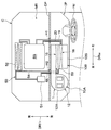
- FIG. 1 It is a schematic block diagram which shows the mounting state to the vehicle of the air-conditioning unit for vehicles which concerns on 1st Embodiment. It is a typical sectional view of an air-conditioning unit for vehicles concerning a 1st embodiment. It is a schematic diagram which shows the refrigerating-cycle apparatus mounted in a vehicle. It is an explanatory view for explaining the flow of the air at the time of the open air mode of the air-conditioning unit for vehicles concerning a 1st embodiment. It is an explanatory view for explaining the flow of the air at the time of interior air mode of the air-conditioning unit for vehicles concerning a 1st embodiment.
- FIG. 1 It is a schematic diagram which shows the air-conditioning unit for vehicles used as the comparative example of the air-conditioning unit for vehicles concerning 1st Embodiment. It is a typical sectional view of an air-conditioning unit for vehicles concerning a 2nd embodiment. It is a typical sectional view of an air-conditioning unit for vehicles concerning a 3rd embodiment. It is a typical sectional view of an air-conditioning unit for vehicles concerning a 4th embodiment. It is a schematic block diagram which shows the mounting state to the vehicle of the air-conditioning unit for vehicles which concerns on 5th Embodiment. It is a typical sectional view of an air-conditioning unit for vehicles concerning a 5th embodiment.
- FIGS. 1 to 6 Shows indicating front and rear in each drawing indicate the front-rear direction DRfr in a state where the vehicle air conditioning unit 1 is mounted on the vehicle C. Arrows indicating left and right in each drawing indicate the left-right direction (that is, the vehicle width direction DRw) in a state where the vehicle air conditioning unit 1 is mounted on the vehicle. Arrows indicating up and down in each drawing indicate up and down directions DRud in a state where the vehicle air conditioning unit 1 is mounted on a vehicle.
- an example in which the vehicle air conditioning unit 1 is applied to a vehicle C provided with a steering wheel Hd on the right side in the vehicle width direction DRw will be described.
- an apparatus accommodation room MR in which an apparatus such as an engine EG is accommodated is divided by a dash panel DP and a vehicle interior.
- a first pipe lead-in hole H1 is provided on the right side in the vehicle width direction DRw, and a second pipe lead-in hole H2 is provided on the left side in the vehicle width direction DRw.
- the vehicle air conditioning unit 1 is disposed inside the instrument panel IP at the front of the vehicle interior. That is, the vehicle air conditioning unit 1 is disposed in a space formed in the vehicle compartment between the instrument panel IP and the dash panel DP.
- the air conditioning unit 1 for the vehicle includes a blower unit 10A for blowing air into the vehicle compartment, a temperature control unit 10B for adjusting the temperature of air blown into the vehicle compartment, and a winder that distributes temperature-controlled air into the vehicle compartment. It has a wind distribution unit.
- a blower unit portion 10A is connected to the air flow upstream side of the temperature control unit portion 10B.
- the temperature control unit 10B is disposed substantially at the center in the vehicle width direction DRw, and the blower unit 10A is offset to the left in the vehicle width direction DRw. That is, the vehicle air conditioning unit 1 has a so-called semi-centered layout.
- the connection portion between the air blowing unit 10A and the temperature control unit 10B extends along the vehicle width direction DRw. It has become.
- the vehicle air conditioning unit 1 is configured to be able to set an inside / outside air double-layer mode in which inside air and outside air are divided and flowed.
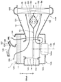
- the internal structure of the vehicle air conditioning unit 1 will be described with reference to FIG.
- the air conditioning unit 1 for vehicles is provided with the air conditioning case 12 which comprises an outer shell.
- the air conditioning case 12 of the present embodiment is configured to include a blower case portion 12A that configures an outer shell of the blower unit portion 10A and a temperature control case portion 12B that configures an outer shell of the temperature control unit portion 10B.
- the air conditioning case 12 is provided with a partition 13 for partitioning the insides of the blower case 12A and the temperature control case 12B into the upper layer passage 121 and the lower layer passage 122.
- the upper layer passage 121 constitutes an outside air passage through which outside air flows in the inside / outside air double-layer mode.
- the lower layer passage 122 constitutes an inside air passage through which inside air flows in the inside / outside air double-layer mode.
- an outside air introduction port 124 for introducing outside air, a first inside air introduction port 125 for introducing inside air into the upper layer passage 121, and a second inside air introduction port for the lower layer passage 122 126 grade is formed.
- a communication passage 127 for communicating the outside air introduction port 124 with the lower layer passage 122 is set so that the outside air can be introduced also to the lower layer passage 122.
- the blower case 12A includes a first inside / outside air switching door 128 for selectively opening / closing the outside air introduction port 124 and the first inside air introduction port 125, a communication passage 127, and a second inside air introduction port 126.
- a second inside / outside air switching door 129 which selectively opens and closes is disposed.
- the first inside / outside air switching door 128 opens the outside air introduction port 124 and closes the first inside air introduction port 125
- the second inside / outside air switching door 129 is the second inside air introduction port 126.
- the communication passage 127 is closed.
- the first inside / outside air switching door 128 and the second inside / outside air switching door 129 are each configured by a rotary door.
- the first inside / outside air switching door 128 and the second inside / outside air switching door 129 may be configured by other doors such as a slide door or a cantilever door.
- An air filter 11 is disposed in the blower case 12A.
- the air filter 11 is provided to remove foreign substances and the like contained in the air introduced from any of the outside air introduction port 124, the first inside air introduction port 125, and the second inside air introduction port 126.
- a blower 14 for generating an air flow toward the vehicle interior On the downstream side of the air flow of the air filter 11 in the air blowing case 12A, a blower 14 for generating an air flow toward the vehicle interior is disposed.
- the blower 14 has an upper layer fan 141 disposed in the upper layer passage 121, a lower layer fan 142 disposed in the lower layer passage 122, and an electric motor 143 for driving the upper layer fan 141 and the lower layer fan 142 to rotate. .
- the blower case 12A is provided with a blower 14 for generating an air flow toward the vehicle interior.
- the blower 14 has an upper layer fan 141 disposed in the upper layer passage 121, a lower layer fan 142 disposed in the lower layer passage 122, and an electric motor 143 for driving the upper layer fan 141 and the lower layer fan 142 to rotate. .
- the upper layer fan 141 and the lower layer fan 142 are configured by centrifugal fans that blow out the air drawn in from the direction of the axis line CL, which is the rotation center, in the direction intersecting the axis line CL.
- the upper layer fan 141 and the lower layer fan 142 are configured as an integral molding integrally molded by a molding technique such as injection molding.
- both a portion for housing the upper layer fan 141 and a portion for housing the lower layer fan 142 are formed in a spiral shape.
- the electric motor 143 is fixed to the bottom of the blower case 12A.
- the electric motor 143 has a rotating shaft 143a that protrudes upward.
- Both the upper layer fan 141 and the lower layer fan 142 are connected to the rotating shaft 143a by a connecting member (not shown).
- the temperature control case portion 12B is connected to the air flow downstream side of the blower 14 in the blower case portion 12A. As shown in FIG. 1, the temperature control case portion 12 ⁇ / b> B accommodates the cooling heat exchanger 16 and the heating heat exchanger 18.
- the cooling heat exchanger 16 is a heat exchanger that cools the air flowing through the inside of the air conditioning case 12 by performing heat exchange between the refrigerant, which is a heat medium, and the air flowing through the inside of the temperature control case 12B of the air conditioning case 12 . As shown in FIG. 2, the cooling heat exchanger 16 is disposed so as to straddle the upper layer passage 121 and the lower layer passage 122 so as to be able to cool both the air flowing through the upper layer passage 121 and the air flowing through the lower layer passage 122. There is.
- the cooling heat exchanger 16 constitutes a vapor compression refrigeration cycle device 50 together with the compressor 51, the radiator 52, and the pressure reducer 53, as shown in FIG.
- the cooling heat exchanger 16 is an evaporator that causes the refrigerant to evaporate by heat exchange between the refrigerant decompressed by the decompressor 53 and the air flowing through the inside of the temperature control case portion 12B.
- the air flowing through the temperature control case portion 12B is cooled by an endothermic effect at the time of evaporation of the refrigerant when passing through the cooling heat exchanger 16.
- the compressor 51 and the radiator 52 are accommodated in the device accommodation room MR.
- the compressor 51 is a device that is driven by an engine EG that generates a driving force for traveling and that compresses a refrigerant.
- the radiator 52 is a heat exchanger which radiates the refrigerant discharged from the compressor 51 by heat exchange with the outside air.
- the decompressor 53 is disposed in the vehicle cabin together with the cooling heat exchanger 16.
- the decompressor 53 is a device that decompresses the refrigerant flowing out of the radiator 52.
- the pressure reducer 53 is disposed adjacent to the cooling heat exchanger 16.
- the refrigerant outlet side of the radiator 52 and the refrigerant inlet side of the decompressor 53 are connected by a high pressure refrigerant pipe 54 through which the high temperature / high pressure refrigerant compressed by the compressor 51 flows.
- the refrigerant suction side of the compressor 51 and the cooling heat exchanger 16 are connected by a low pressure refrigerant pipe 55 through which the low temperature and low pressure refrigerant flowing out of the cooling heat exchanger 16 flows.
- the high-temperature and high-pressure refrigerant discharged from the compressor 51 flows through the radiator 52 ⁇ the high pressure refrigerant pipe 54 ⁇ the pressure reducer 53 ⁇ the cooling heat exchanger 16 ⁇ the low pressure refrigerant pipe 55 in this order. Inhaled by
- the refrigerant is supplied to the cooling heat exchanger 16 via the high pressure refrigerant pipe 54, and the refrigerant is discharged from the cooling heat exchanger 16 via the low pressure refrigerant pipe 55.
- the high pressure refrigerant pipe 54 constitutes a heat medium supply pipe for supplying the refrigerant as the heat medium to the heat exchanger 16 for cooling
- the low pressure refrigerant pipe 55 is a heat exchanger for cooling
- a heat medium discharge pipe for discharging the refrigerant which is a heat medium from 16 is constituted.
- the high pressure refrigerant pipe 54 constitutes a high temperature pipe
- the low pressure refrigerant pipe 55 constitutes a low temperature pipe.
- the compressor 51 and the radiator 52 are disposed in the equipment storage room MR, while the decompressor 53 and the cooling heat exchanger 16 are disposed in the vehicle compartment. . Therefore, the high pressure refrigerant pipe 54 and the low pressure refrigerant pipe 55 are drawn into the vehicle compartment from the device accommodation room MR via the second pipe lead-in hole H2 provided in the dash panel DP.
- a heating heat exchanger 18 for heating the air that has passed through the cooling heat exchanger 16 is disposed downstream of the cooling heat exchanger 16 with respect to the air flow.
- the heating heat exchanger 18 exchanges heat between the cooling water for cooling the engine EG, which is a heat medium, and the air flowing through the inside of the temperature control case portion 12B of the air conditioning case 12 to heat the air flowing through the inside of the air conditioning case 12 Heat exchanger.
- the heating heat exchanger 18 is disposed so as to straddle the upper layer passage 121 and the lower layer passage 122 so as to be able to heat both the air flowing through the upper layer passage 121 and the air flowing through the lower layer passage 122.
- high temperature water piping 19 through which high temperature cooling water heated by the engine EG flows, and low temperature cooling water having passed through the heating heat exchanger 18 are returned to the engine EG side.
- Low temperature water piping 20 is connected.
- the high temperature water piping 19 and the low temperature water piping 20 are drawn into the vehicle compartment from the device storage room MR via a first piping lead-in hole H1 provided in the dash panel DP.
- a bypass passage is formed in the temperature control case portion 12B for bypassing the heating heat exchanger 18 and allowing air to flow, and the air flow of the air passing through the heating heat exchanger 18 and the bypass passage
- An air mix door is arranged to adjust the ratio of the air volume to the volume of air.
- a wind distribution unit portion is connected to the temperature control case portion 12B on the air flow downstream side of the heating heat exchanger 18 and the bypass passage.
- the air distribution unit portion includes a defroster blowout portion that blows air toward the front glass of the vehicle C, a face blowout portion that blows air toward the upper body of the occupant, and a foot that blows air toward the lower body of the occupant It has a blowout part. Further, the air distribution unit portion is provided with a mode switching mechanism for changing the blowing mode of the air into the vehicle compartment.
- connection portion between the blower unit portion 10A and the temperature control unit portion 10B overlaps the second pipe lead-in hole H2 in the longitudinal direction DRfr of the vehicle.
- the high-pressure refrigerant pipe 54 and the low-pressure refrigerant pipe 55 may be bent in accordance with the outer shape of the air-conditioning case 12 in order to avoid interference between the high-pressure refrigerant pipe 54 and the low-pressure refrigerant pipe 55 and the air conditioning case 12 .
- the pressure loss in the refrigeration cycle apparatus 50 may increase or the physical size of the vehicle air conditioning unit 1 may increase.
- the vehicle air conditioning unit 1 of the present embodiment has a structure in which the high pressure refrigerant piping 54 and the low pressure refrigerant piping 55 connected to the cooling heat exchanger 16 with respect to the air conditioning case 12 penetrate.
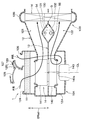
- the vehicle air conditioning unit 1 has a single through hole 130 for allowing the high pressure refrigerant piping 54 and the low pressure refrigerant piping 55 to penetrate through the partition 13 set inside the air conditioning case 12. Is formed.
- the through holes 130 extend in a direction (in this example, the front-rear direction DRfr) substantially perpendicular to the air flow flowing through the upper layer passage 121 and the lower layer passage 122.
- the partition wall portion 13 includes a first bulging wall portion 131 bulging toward the upper layer passage 121 and a bulging portion toward the lower layer passage 122 at a portion between the blower 14 and the cooling heat exchanger 16.
- a second bulging wall 132 is provided.
- a through hole 130 for penetrating the high pressure refrigerant pipe 54 and the low pressure refrigerant pipe 55 is formed by the gap between the first expanded wall portion 131 and the second expanded wall portion 132.
- the through hole 130 has a dimension in the vertical direction DRud so that the high pressure refrigerant pipe 54 and the low pressure refrigerant pipe 55 can be arranged side by side along the alignment direction of the upper layer passage 121 and the lower layer passage 122.
- the first bulging wall portion 131 and the second bulging wall portion 132 have a vertically symmetrical shape so as to project substantially equally to both the upper layer passage 121 and the lower layer passage 122.
- the first bulging wall portion 131 and the second bulging wall portion 132 of the present embodiment each have a shape bent in an L shape so that a rhombic through hole 130 is formed. ing.
- the high-pressure refrigerant pipe 54 and the low-pressure refrigerant pipe 55 are inserted in a bundled state with respect to a single through hole 130 formed for the partition 13.
- the high pressure refrigerant piping 54 and the low pressure refrigerant piping 55 of the present embodiment are arranged in the through hole 130 so as to be aligned in the alignment direction of the upper layer passage 121 and the lower layer passage 122 (that is, the up and down direction DRud).
- the high pressure refrigerant piping 54 and the low pressure refrigerant piping 55 of the present embodiment are inserted through the through hole 130 in a state of being bundled so as to overlap each other in the vertical direction DRud.
- the low pressure refrigerant pipe 55 is disposed closer to the upper layer passage 121 than the high pressure refrigerant pipe 54 in the through hole 130.
- the low pressure refrigerant pipe 55 is disposed above the high pressure refrigerant pipe 54 in the through hole 130 so as to be closer to the first expanded wall 131 than the second expanded wall 132. .
- the high pressure refrigerant pipe 54 is disposed closer to the lower layer passage 122 than the low pressure refrigerant pipe 55 in the through hole 130.
- the high pressure refrigerant pipe 54 is disposed below the low pressure refrigerant pipe 55 in the through hole 130 so as to be closer to the second expanded wall 132 than the first expanded wall 131. .
- the air conditioning unit 1 of the vehicle is configured to be able to set the air suction mode to an outside air mode introducing only outside air, an inside air mode introducing only inside air, and an inside / outside air double layer mode separating and introducing inside air and outside air ing.
- the control process of various devices including the switching control of the suction mode is executed by a control device (not shown).
- the controller comprises a known microcomputer including a processor and a memory and its peripheral circuits.
- the control device sets the first inside / outside air switching door 128 at a position where the outside air introduction port 124 is opened and the first inside air introduction port 125 is closed. Further, in the outside air mode, the control device sets the second inside / outside air switching door 129 at a position where the communication passage 127 is opened and the second inside air introduction port 126 is closed.
- the air introduced into the upper layer passage 121 and the lower layer passage 122 flows into the cooling heat exchanger 16 via the fans 141 and 142 of the blower 14 and is cooled to a predetermined temperature.
- the air having passed through the cooling heat exchanger 16 is adjusted to a desired temperature by being mixed after passing through at least one of the heating heat exchanger 18 and the bypass passage.
- the temperature-controlled air is blown out as a conditioned air to a desired location in the vehicle compartment via the air distribution unit.
- In the outside air mode it is possible to ventilate the interior of the vehicle by introducing fresh air outside the vehicle or to suppress window fogging by introducing dry air outside the vehicle.
- the control device sets the first inside / outside air switching door 128 to a position where the first inside air introduction port 125 is opened and the outside air introduction port 124 is closed.
- the second inside / outside air switching door 129 is set to a position where the second inside air introduction port 126 is opened and the communication passage 127 is closed by the control device.
- the inside air introduced from the first inside air introduction port 125 is introduced into the upper layer passage 121 and the inside air introduced from the second inside air introduction port 126 is the lower layer passage. It is introduced at 122.
- the air introduced into the upper layer passage 121 and the lower layer passage 122 flows into the cooling heat exchanger 16 via the fans 141 and 142 of the blower 14 and is cooled to a predetermined temperature.
- the air having passed through the cooling heat exchanger 16 is adjusted to a desired temperature by being mixed after passing through at least one of the heating heat exchanger 18 and the bypass passage.
- the temperature-controlled air is blown out as a conditioned air to a desired location in the vehicle compartment via the air distribution unit.
- the air conditioning efficiency can be improved by circulating the air in the vehicle compartment.
- the control device as shown in FIG. It is set. Further, in the inside / outside air double layer mode, the second inside / outside air switching door 129 is set to a position where the second inside air introduction port 126 is opened and the communication passage 127 is closed by the control device.
- the outside air introduced into the upper layer passage 121 and the inside air introduced into the lower layer passage 122 are blown toward the cooling heat exchanger 16 by the fans 141 and 142 of the blower 14.
- path 121 becomes a flow of diagonally upward with the 1st bulging wall part 131 which comprises the through-hole 130.
- the inside air flowing along the partition wall 13 in the lower layer passage 122 has a diagonally downward flow by the second bulging wall portion 132 constituting the through hole 130.
- the vehicle air conditioning unit 1 has a structure capable of sufficiently securing the inside-outside air separation.
- Outside air flowing in the upper layer passage 121 flows into the cooling heat exchanger 16 and is cooled to a predetermined temperature, passes through at least one of the heating heat exchanger 18 and the bypass passage, and then passes through the defroster blowout portion of the wind distribution unit. It blows out near the windshield of the vehicle interior. Thereby, the window fogging of the windshield is suppressed.
- the inside air flowing through the lower layer passage 122 flows into the cooling heat exchanger 16, is cooled to a predetermined temperature, and passes through at least one of the heating heat exchanger 18 and the bypass passage, It is blown out toward the passenger in the vehicle compartment via
- a comfortable air-conditioning feeling can be provided to the occupant.
- the vehicle air conditioning unit 1 described above is configured to be able to set the inside / outside air two-layer mode. Therefore, the vehicle air conditioning unit 1 can suppress window fogging while suppressing ventilation loss.
- FIG. 6 is a schematic view showing a vehicle air conditioning unit CE which is a comparative example of the vehicle air conditioning unit 1 of the present embodiment.
- a through hole TH for allowing the high pressure refrigerant piping 54 and the low pressure refrigerant piping 55 to pass through is formed in a portion of the air conditioning case 12 forming the upper layer passage 121 in this embodiment. This is different from the vehicle air conditioning unit 1 of FIG.
- the same components as the vehicle air conditioning unit 1 of the present embodiment in the vehicle air conditioning unit CE of the comparative example are given the same reference numerals as the vehicle air conditioning unit 1 of the present embodiment. .
- a through hole TH for allowing the high pressure refrigerant piping 54 and the low pressure refrigerant piping 55 to penetrate is provided in a portion of the air conditioning case 12 forming the upper layer passage 121. There is.
- the high pressure refrigerant pipe 54 and the low pressure refrigerant pipe 55 are disposed to penetrate the upper layer passage 121.
- the other configuration of the vehicle air conditioning unit CE of the comparative example is configured in the same manner as the vehicle air conditioning unit 1 of the present embodiment.
- the control device sets the first inside / outside air switching door 128 to a position where the outside air introduction port 124 is opened, and the second inside / outside air switching door 129 opens the second inside air introduction port 126 Set to position.
- the outside air introduced into the upper layer passage 121 and the inside air introduced into the lower layer passage 122 are blown toward the cooling heat exchanger 16 by the fans 141 and 142 of the blower 14.
- path 122 flows into the heat exchanger 16 for cooling as it is, without being divided by bifurcating.
- the outside air flowing through the upper layer passage 121 collides with the refrigerant pipes 54 and 55 and is divided into upper and lower parts, and then flows into the cooling heat exchanger 16. That is, in the upper layer passage 121, the ventilation resistance increases due to the change in the passage shape and the branching loss caused by the penetration of the refrigerant pipes 54 and 55.
- the through holes 130 through which the high pressure refrigerant piping 54 and the low pressure refrigerant piping 55 are penetrated are formed in the partition portion 13.
- one of the upper layer passage 121 and the lower layer passage 122 does not branch up and down by the angular refrigerant pipes 54 and 55 or the like.
- an increase in ventilation resistance caused by penetrating the refrigerant pipes 54, 55 is higher than the upper layer passage 121 and the lower layer, as compared with the vehicle air conditioning unit CE of the comparative example. It is possible to prevent the one of the passages 122 from being biased. Therefore, according to the vehicle air conditioning unit 1 of the present embodiment, the air volume ratio of the upper layer passage 121 and the lower layer passage 122 caused by causing the air conditioning case 12 to penetrate the refrigerant pipes 54 and 55 in the internal / external air double layer mode Change can be suppressed.
- the low pressure refrigerant pipe 55 is disposed closer to the upper layer passage 121 than the high pressure refrigerant pipe 54 in the through hole 130, and the high pressure refrigerant pipe 54 is a low pressure refrigerant pipe in the through hole 130. It is disposed closer to the lower layer passage 122 than 55.
- the inside air flowing through the lower layer passage 122 and the low pressure refrigerant pipe 55 are Heat loss due to heat exchange is suppressed. As a result, it is possible to improve the heating efficiency of the vehicle air conditioning unit 1 by introducing the inside air.
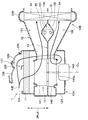
- the shape of the through hole 130 formed in the partition 13 is different from that of the first embodiment.
- the through hole 130 of the present embodiment is shaped such that the high pressure refrigerant pipe 54 and the low pressure refrigerant pipe 55 can be arranged side by side along the air flow direction in the upper layer passage 121 and the lower layer passage 122. That is, in the through hole 130, the dimension in the air flow direction in the upper layer passage 121 and the lower layer passage 122 is larger than the dimension in the alignment direction of the upper layer passage 121 and the lower layer passage 122.
- the through hole 130 has a dimension in the air flow direction in the upper layer passage 121 and the lower layer passage 122 larger than the sum of the pipe diameter of the high pressure refrigerant pipe 54 and the pipe diameter of the low pressure refrigerant pipe 55. Further, in the through hole 130, the dimension in the direction in which the upper layer passage 121 and the lower layer passage 122 are aligned is smaller than the sum of the pipe diameter of the high pressure refrigerant pipe 54 and the pipe diameter of the low pressure refrigerant pipe 55.
- first bulging wall portion 131A and the second bulging wall portion 132A in the direction of projecting toward the upper layer passage 121 and the lower layer passage 122 are shorter than those in the first embodiment.
- first bulging wall portion 131A and the second bulging wall portion 132A each have a bent shape so that a hexagonal through hole 130 is formed.
- the first bulging wall portion 131A and the second bulging wall portion 132A of the present embodiment have a vertically symmetrical shape so as to project substantially equally to both the upper layer passage 121 and the lower layer passage 122. doing.
- the high pressure refrigerant pipe 54 and the low pressure refrigerant pipe 55 are arranged along the flow direction of the air flowing through the upper layer passage 121 and the lower layer passage 122 in the through hole 130.
- the high-pressure refrigerant pipe 54 and the low-pressure refrigerant pipe 55 are inserted into the through hole 130 in a state of being bundled so as to overlap each other in the flow direction of the air flowing through the upper layer passage 121 and the lower layer passage 122.
- the low pressure refrigerant pipe 55 is disposed at a position on the through hole 130 on the upstream side of the air flow of the upper layer passage 121 and the lower layer passage 122 with respect to the high pressure refrigerant pipe 54.
- the low pressure refrigerant pipe 55 is disposed at a position closer to the blower 14 than the high pressure refrigerant pipe 54 in the through hole 130.
- the high pressure refrigerant pipe 54 is disposed at the downstream side of the through holes 130 in the air flow of the upper layer passage 121 and the lower layer passage 122 with respect to the low pressure refrigerant pipe 55.
- the high pressure refrigerant pipe 54 is disposed at a position closer to the cooling heat exchanger 16 than the low pressure refrigerant pipe 55 in the through hole 130.
- the other configuration is the same as that of the first embodiment.
- the vehicle air conditioning unit 1 of the present embodiment can obtain the same advantages as the first embodiment, with the same advantages as those of the first embodiment.
- the high pressure refrigerant pipe 54 and the low pressure refrigerant pipe 55 are arranged in the air flow direction inside the air conditioning case 12.
- the abrupt change of the passage shape in the upper layer passage 121 and the lower layer passage 122 Is suppressed. Therefore, the ventilation resistance of the upper layer passage 121 and the lower layer passage 122 resulting from the penetration of the high pressure refrigerant pipe 54 and the low pressure refrigerant pipe 55 with respect to the air conditioning case 12 can be sufficiently suppressed.
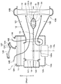
- the high pressure refrigerant piping 54 and the low pressure refrigerant piping 55 are arranged in the through hole 130 in the alignment direction of the upper layer passage 121 and the lower layer passage 122 (that is, vertical direction DRud). It is arranged as.
- the high pressure refrigerant pipe 54 is disposed closer to the upper layer passage 121 than the low pressure refrigerant pipe 55 in the through hole 130.
- the high pressure refrigerant pipe 54 is disposed above the low pressure refrigerant pipe 55 in the through hole 130 so as to be closer to the first expanded wall 131 than the second expanded wall 132. .
- the low pressure refrigerant pipe 55 is disposed closer to the lower layer passage 122 than the high pressure refrigerant pipe 54 in the through hole 130.
- the low pressure refrigerant pipe 55 is disposed below the high pressure refrigerant pipe 54 in the through hole 130 so as to be closer to the second expanded wall 132 than the first expanded wall 131. .
- the other configuration is the same as that of the first embodiment.
- the vehicle air conditioning unit 1 of the present embodiment can obtain the same advantages as the first embodiment, with the same advantages as those of the first embodiment.
- the high pressure refrigerant pipe 54 is disposed closer to the upper layer passage 121 than the low pressure refrigerant pipe 55 in the through hole 130, and the low pressure refrigerant pipe 55 is a high pressure refrigerant pipe in the through hole 130. It is disposed closer to the lower layer passage 122 than 54.
- the high pressure refrigerant pipe 54 when the high pressure refrigerant pipe 54 having a temperature higher than that of the low pressure refrigerant pipe 55 is disposed on the upper layer passage 121 side, the high pressure refrigerant pipe 54 flows when the outside air flowing through the upper layer passage 121 flows around the through hole 130. Receive heat from and heat up. That is, according to the configuration of the present embodiment, the high pressure refrigerant pipe 54 can be used as an auxiliary heat source for raising the temperature of the outside air flowing through the upper layer passage 121 in the inside / outside air double layer mode. As a result, the heating efficiency of the vehicle air conditioning unit 1 can be improved.
- the high pressure refrigerant pipe 54 is disposed at a position on the upstream side of the upper layer passage 121 and the lower layer passage 122 of the through hole 130 on the air flow upstream side of the low pressure refrigerant pipe 55.
- the high pressure refrigerant pipe 54 is disposed at a position closer to the blower 14 than the low pressure refrigerant pipe 55 in the through hole 130.
- the low pressure refrigerant pipe 55 is disposed at the downstream side of the through hole 130 on the air flow downstream side of the upper layer passage 121 and the lower layer passage 122 than the high pressure refrigerant pipe 54.
- the low pressure refrigerant pipe 55 is disposed at a position closer to the cooling heat exchanger 16 than the high pressure refrigerant pipe 54 in the through hole 130.
- the other configuration is the same as that of the second embodiment.
- the vehicle air conditioning unit 1 of the present embodiment can obtain the same advantages as the second embodiment, with the same advantages as those of the second embodiment.
- the high pressure refrigerant pipe 54 is disposed upstream of the low pressure refrigerant pipe 55 in the through hole 130 in the air flow direction of the air conditioning case 12. According to this, when the outside air flowing through the upper layer passage 121 and the inside air flowing through the lower layer passage 122 flow near the through hole 130, the heat is received from the high pressure refrigerant pipe 54 and the temperature is raised. That is, according to the configuration of the present embodiment, the high-pressure refrigerant pipe 54 can be used as an auxiliary heat source for raising the temperature of the outside air flowing through the upper layer passage 121 and the inside air flowing through the lower layer passage 122 in the inside / outside air double layer mode. As a result, the heating efficiency of the vehicle air conditioning unit 1 can be improved.
- the air flowing along the partition 13 in the upper layer passage 121 is directed obliquely upward by the air flow upstream side of the first bulging wall 131 that constitutes the through hole 130. Further, the air flowing along the partition wall 13 in the lower layer passage 122 is directed obliquely downward by the air flow upstream side of the second bulging wall portion 132 constituting the through hole 130.
- the outside air flowing through the upper layer passage 121 and the inside air flowing through the lower layer passage 122 are less likely to flow along the downstream portion of the air flow of the bulging wall portions 131 and 132. Heat exchange is suppressed.
- the present embodiment is different from the first embodiment in that the vehicle air conditioning unit 1 is applied to a vehicle C in which the steering wheel Hd is disposed on the left side in the vehicle width direction DRw.
- the temperature control unit unit 10B is disposed substantially at the center in the vehicle width direction DRw, and the blower unit unit 10A is offset to the right in the vehicle width direction DRw. It has become.
- the blower unit portion 10A is offset to the right in the vehicle width direction DRw so that the connection portion between the blower unit portion 10A and the temperature control unit portion 10B extends along the vehicle width direction DRw. It has become.
- connection portion between the blower unit portion 10A and the temperature control unit portion 10B overlaps the first pipe lead-in hole H1 in the longitudinal direction DRfr of the vehicle.
- the high temperature water piping 19 and the low temperature water piping 20 are air conditioning case 12 It may be bent according to the outer shape of.
- the vehicle air conditioning unit 1 has a structure in which the high temperature water piping 19 and the low temperature water piping 20 connected to the heating heat exchanger 18 pass through the air conditioning case 12.
- the connection portion between the blower unit portion 10A and the temperature control unit portion 10B does not overlap the second pipe lead-in hole H2 in the longitudinal direction DRfr of the vehicle. Therefore, in the vehicle air conditioning unit 1 of the present embodiment, the high pressure refrigerant piping 54 and the low pressure refrigerant piping 55 do not penetrate the air conditioning case 12.
- the vehicle air conditioning unit 1 has a single through hole 130 for allowing the high temperature water piping 19 and the low temperature water piping 20 to penetrate through the partition 13 set inside the air conditioning case 12. Is formed.
- the through holes 130 extend in a direction (in this example, the front-rear direction DRfr) substantially perpendicular to the air flow flowing through the upper layer passage 121 and the lower layer passage 122.
- the partition wall portion 13 includes a first bulging wall portion 131 bulging toward the upper layer passage 121 and a bulging portion toward the lower layer passage 122 at a portion between the blower 14 and the cooling heat exchanger 16.
- a second bulging wall 132 is provided.
- the penetration hole 130 for making the high temperature water piping 19 and the low temperature water piping 20 penetrate is formed.
- the 1st bulging wall part 131 and the 2nd bulging wall part 132 of this embodiment are comprised similarly to 1st Embodiment, the description is abbreviate
- the high temperature water piping 19 and the low temperature water piping 20 are inserted in a bundled state with respect to a single through hole 130 formed to the partition 13.
- the high temperature water piping 19 and the low temperature water piping 20 are arranged in the through hole 130 so as to be aligned in the alignment direction of the upper layer passage 121 and the lower layer passage 122 (that is, the vertical direction DRud).
- the low temperature water pipe 20 is disposed in the through hole 130 closer to the upper layer passage 121 than the high temperature water pipe 19.
- the low temperature water pipe 20 is disposed above the high temperature water pipe 19 in the through hole 130 so as to be closer to the first expanded wall portion 131 than the second expanded wall portion 132. .
- the high temperature water pipe 19 is disposed closer to the lower layer passage 122 than the low temperature water pipe 20 in the through hole 130.
- the high temperature water pipe 19 is disposed below the low temperature water pipe 20 in the through hole 130 so as to be closer to the second expanded wall portion 132 than the first expanded wall portion 131. .
- the other configuration is the same as that of the first embodiment.
- the vehicle air conditioning unit 1 of the present embodiment can obtain the same advantages as the first embodiment, with the same advantages as those of the first embodiment. That is, the vehicle air conditioning unit 1 can suppress an increase in the ventilation resistance caused by penetrating the hot water pipes 19 and 20 with respect to the air conditioning case 12 from being biased to one of the upper layer passage 121 and the lower layer passage 122 . Therefore, according to the vehicle air conditioning unit 1 of the present embodiment, the air volume ratio of the upper layer passage 121 and the lower layer passage 122 caused by causing the hot water pipes 19 and 20 to penetrate the air conditioning case 12 in the inside / outside air double layer mode. Change can be suppressed.
- the cooling water of the engine EG is supplied to the heating heat exchanger 18 via the high temperature water piping 19, and the cooling water is discharged from the heating heat exchanger 18 via the low temperature water piping 20.
- the high temperature water pipe 19 constitutes a heat medium supply pipe for supplying the cooling water as a heat medium to the heating heat exchanger 18, and the low temperature water pipe 20 serves as a heat exchange for heating.
- the heat medium discharge pipe for discharging the cooling water which is a heat medium from the vessel 18 is configured.
- the high temperature water pipe 19 constitutes a high temperature pipe
- the low temperature water pipe 20 constitutes a low temperature pipe.
- the low temperature water pipe 20 is disposed on the upper layer passage 121 side of the through holes 130, and the high temperature water pipe 19 is disposed on the lower layer passage 122 side of the through holes 130. It is not limited to.
- the high temperature water piping 19 is disposed on the upper layer passage 121 side of the through holes 130, and the low temperature water piping 20 is disposed on the lower layer passage 122 side of the through holes 130. It is also good. Also, for example, one of the high-temperature water piping 19 and the low-temperature water piping 20 is disposed on the upstream side of the air flow inside the air conditioning case 12 relative to the other piping. It may be
- the vehicle air conditioning unit 1 may have a configuration in which two through holes are formed in the partition 13 and the refrigerant pipes 54 and 55 are individually inserted into the respective through holes.
- the through hole 130 may be formed by the first bulging wall portion 131 and the second bulging wall portion 132 which are vertically asymmetric.
- the through hole 130 may be formed by a bulging wall portion bulging toward one of the upper layer passage 121 and the lower layer passage 122 and a flat wall portion.
- each embodiment explained the example which applies air-conditioning unit 1 for vehicles of this indication to vehicles C in which two piping lead-in holes H1 and H2 are formed to dash panel DP, It is not limited to.
- the vehicle air conditioning unit 1 of the present disclosure is also applicable to, for example, a vehicle C in which a single pipe lead-in hole is formed in the dash panel DP.
- the refrigerant pipes 54 and 55 and the hot water pipes 19 and 20 are inserted in a bundle in a single pipe lead-in hole.
- the vehicle air conditioning unit 1 has, for example, a configuration in which the blower 14 is disposed between the cooling heat exchanger 16 and the heating heat exchanger 18, or is disposed downstream of the heating heat exchanger 18 in the air flow direction.
- the configuration may be
- the cooling heat exchanger 16 may be, for example, a heat exchanger into which the fluid cooled by the evaporator of the refrigeration cycle apparatus 50 is introduced.
- each embodiment demonstrated the example which employ
- the heat exchanger 16 for cooling may be comprised, for example with the heat exchanger which thermally radiates the cooling water of apparatuses (for example, high voltage battery) other than engine EG.
- each embodiment illustrated the composition by which ventilation unit part 10A is offset arranged by the side of temperature control unit part 10B as air-conditioning unit 1 for vehicles, it is not limited to this.
- the vehicle air conditioning unit 1 may have a layout with a center, in which both the blower unit 10A and the temperature control unit 10B are disposed substantially in the center in the vehicle width direction DRw.
- a vehicle air conditioning unit includes an air conditioning case, a heat exchanger disposed inside the air conditioning case, and a heat exchanger.
- a heat medium supply pipe for supplying a heat medium and a heat medium discharge pipe for discharging the heat medium from the heat exchanger are provided.
- Inside the air conditioning case there are provided a partition for forming an outside air passage for flowing outside air in the inside / outside air double layer mode and an inside air passage for flowing inside air in the inside / outside air double layer mode. Further, through holes are formed in the partition wall for passing through the heat medium supply pipe and the heat medium discharge pipe.
- the heat medium supply pipe and the heat medium discharge pipe of the vehicle air conditioning unit constitute a high temperature pipe in which a heat medium having a temperature higher than that of the heat medium flowing through the other pipe flows
- Tubes constitute low temperature piping.
- the low temperature piping is disposed on the outside air passage side of the through holes in comparison with the high temperature piping.
- high temperature piping is arranged in the inside air passage side compared with low temperature piping among the penetration holes.
- the heat loss due to the heat exchange between the low temperature piping and the inside air flowing through the inside air passage in the inside / outside air double layer mode is suppressed.
- the heating efficiency of the air conditioning unit can be improved.
- the heat medium supply pipe and the heat medium discharge pipe of the air conditioning unit for a vehicle are arranged in the through hole along the air flow direction of the air flowing inside the air conditioning case. It is arrange
- the rapid change of the passage shape in the inside air passage and the outside air passage is suppressed. Therefore, it is possible to sufficiently suppress the ventilation resistance of the outside air passage and the inside air passage resulting from the heat medium supply pipe and the heat medium discharge pipe penetrating the air conditioning case.
- the heat medium supply pipe and the heat medium discharge pipe of the vehicle air conditioning unit constitute a high temperature pipe in which a heat medium having a temperature higher than that of the heat medium flowing through the other pipe flows Tubes constitute low temperature piping.
- the high temperature piping can be used as an auxiliary heat source at the time of heating the vehicle interior, so that the heating efficiency in the vehicle air conditioning unit can be improved. it can.
- the heat medium supply pipe and the heat medium discharge pipe of the vehicle air conditioning unit constitute a high temperature pipe in which a heat medium having a temperature higher than that of the heat medium flowing through the other pipe flows
- Tubes constitute low temperature piping.
- the low temperature piping is disposed on the inside air passage side of the through holes in comparison with the high temperature piping.
- high temperature piping is arranged at the open air passage side compared with low temperature piping among the penetration holes.
- the high temperature piping can be used as an auxiliary heat source for raising the temperature of the outside air in the internal / external air double layer mode, so the heating efficiency in the vehicle air conditioning unit is improved.
- the heat medium supply pipe and the heat medium discharge pipe of the air conditioning unit for a vehicle are inserted into a single through hole in a state of being bundled so as to be adjacent to each other. According to this, since it is only necessary to provide a single through hole inside the air conditioning case, the structure for allowing the heat medium supply pipe and the heat medium discharge pipe to penetrate the air conditioning case can be simplified.
- the heat exchanger of the vehicle air conditioning unit exchanges heat between the heat medium and the air flowing inside the air conditioning case to cool the air flowing inside the air conditioning case as a cooling heat exchanger. It is configured.
- the internal / external air double layer mode It is possible to suppress changes in the air volume ratio of the outside air passage and the inside air passage at the time.
- the heat exchanger of the vehicle air conditioning unit heats the air flowing inside the air conditioning case by heat exchange between the heat medium and the air flowing inside the air conditioning case, thereby heating the air flowing inside the air conditioning case. It is configured. When it is necessary to penetrate the heat medium supply pipe and the heat medium discharge pipe connected to the heat exchanger for heating with respect to the air conditioning case, by arranging each pipe in the through hole of the partition, the inside / outside air double layer mode It is possible to suppress changes in the air volume ratio of the outside air passage and the inside air passage at the time.
Landscapes
- Physics & Mathematics (AREA)
- Thermal Sciences (AREA)
- Engineering & Computer Science (AREA)
- Mechanical Engineering (AREA)
- Air-Conditioning For Vehicles (AREA)
Priority Applications (1)
| Application Number | Priority Date | Filing Date | Title |
|---|---|---|---|
| CN201880086017.XA CN111565947B (zh) | 2018-01-11 | 2018-11-29 | 车辆用空调单元 |
Applications Claiming Priority (2)
| Application Number | Priority Date | Filing Date | Title |
|---|---|---|---|
| JP2018-002663 | 2018-01-11 | ||
| JP2018002663A JP6836203B2 (ja) | 2018-01-11 | 2018-01-11 | 車両用空調ユニット |
Publications (1)
| Publication Number | Publication Date |
|---|---|
| WO2019138719A1 true WO2019138719A1 (ja) | 2019-07-18 |
Family
ID=67218248
Family Applications (1)
| Application Number | Title | Priority Date | Filing Date |
|---|---|---|---|
| PCT/JP2018/043965 Ceased WO2019138719A1 (ja) | 2018-01-11 | 2018-11-29 | 車両用空調ユニット |
Country Status (3)
| Country | Link |
|---|---|
| JP (1) | JP6836203B2 (https=) |
| CN (1) | CN111565947B (https=) |
| WO (1) | WO2019138719A1 (https=) |
Citations (7)
| Publication number | Priority date | Publication date | Assignee | Title |
|---|---|---|---|---|
| JPH0958256A (ja) * | 1995-08-23 | 1997-03-04 | Zexel Corp | 車両用空調ユニット |
| JPH09104216A (ja) * | 1995-10-12 | 1997-04-22 | Denso Corp | 空調装置 |
| JPH09175157A (ja) * | 1995-12-27 | 1997-07-08 | Denso Corp | 自動車用空調装置 |
| JP2002012021A (ja) * | 2000-06-29 | 2002-01-15 | Denso Corp | 車両用空調ユニット |
| JP2004101079A (ja) * | 2002-09-10 | 2004-04-02 | Denso Corp | 空調ユニット |
| JP2006281905A (ja) * | 2005-03-31 | 2006-10-19 | Denso Corp | 車両用空調装置 |
| JP2008254576A (ja) * | 2007-04-04 | 2008-10-23 | Denso Corp | 車両用空調装置 |
Family Cites Families (4)
| Publication number | Priority date | Publication date | Assignee | Title |
|---|---|---|---|---|
| DE102012106619A1 (de) * | 2012-07-20 | 2014-01-23 | Halla Visteon Climate Control Corporation 95 | Luftführendes Übergangselement eines Kraftfahrzeugklimagerätes |
| WO2015011919A1 (ja) * | 2013-07-26 | 2015-01-29 | パナソニックIpマネジメント株式会社 | 車両用空調装置 |
| US10434843B2 (en) * | 2015-03-03 | 2019-10-08 | Denso Corporation | Air-conditioning unit for vehicle |
| JP2017129028A (ja) * | 2016-01-18 | 2017-07-27 | 株式会社デンソー | 送風機 |
-
2018
- 2018-01-11 JP JP2018002663A patent/JP6836203B2/ja not_active Expired - Fee Related
- 2018-11-29 WO PCT/JP2018/043965 patent/WO2019138719A1/ja not_active Ceased
- 2018-11-29 CN CN201880086017.XA patent/CN111565947B/zh active Active
Patent Citations (7)
| Publication number | Priority date | Publication date | Assignee | Title |
|---|---|---|---|---|
| JPH0958256A (ja) * | 1995-08-23 | 1997-03-04 | Zexel Corp | 車両用空調ユニット |
| JPH09104216A (ja) * | 1995-10-12 | 1997-04-22 | Denso Corp | 空調装置 |
| JPH09175157A (ja) * | 1995-12-27 | 1997-07-08 | Denso Corp | 自動車用空調装置 |
| JP2002012021A (ja) * | 2000-06-29 | 2002-01-15 | Denso Corp | 車両用空調ユニット |
| JP2004101079A (ja) * | 2002-09-10 | 2004-04-02 | Denso Corp | 空調ユニット |
| JP2006281905A (ja) * | 2005-03-31 | 2006-10-19 | Denso Corp | 車両用空調装置 |
| JP2008254576A (ja) * | 2007-04-04 | 2008-10-23 | Denso Corp | 車両用空調装置 |
Also Published As
| Publication number | Publication date |
|---|---|
| JP6836203B2 (ja) | 2021-02-24 |
| CN111565947B (zh) | 2023-02-17 |
| JP2019119419A (ja) | 2019-07-22 |
| CN111565947A (zh) | 2020-08-21 |
Similar Documents
| Publication | Publication Date | Title |
|---|---|---|
| CN105307880B (zh) | 车辆用空调装置 | |
| EP3536526B1 (en) | Air conditioning unit for vehicle | |
| US9446654B2 (en) | Vehicle air conditioner | |
| WO2015004858A1 (ja) | 車両用空調装置 | |
| JP5911728B2 (ja) | 気液分離器及び車両用空気調和装置 | |
| JP6281362B2 (ja) | 車両用空調ユニット | |
| JP6269561B2 (ja) | 車両用空調ユニット | |
| CN104619531B (zh) | 车辆用空调装置 | |
| CN107531129A (zh) | 车辆用空调单元 | |
| JP5353665B2 (ja) | 車両用空調装置 | |
| WO2015146058A1 (ja) | 車両用空調ユニット | |
| WO2018083940A1 (ja) | 車両用空調ユニット | |
| WO2019138719A1 (ja) | 車両用空調ユニット | |
| JP2019206205A (ja) | 車両用空調装置 | |
| JP5127204B2 (ja) | 車両用空調装置 | |
| JP2008265447A (ja) | 車両用空調装置 | |
| JP7659082B2 (ja) | 車両用空調装置 | |
| JP2010188982A (ja) | 空気調和ユニット及び車両用空調装置 | |
| JP2010036738A (ja) | 車両用空調装置 | |
| JP2006137303A (ja) | 車両用空調装置 | |
| JP2019051819A (ja) | 車両用空調装置 | |
| JP4815495B2 (ja) | 車両用空気調和装置 | |
| JP4789579B2 (ja) | 車両用空調装置 | |
| JP2010036737A (ja) | 車両用空調装置 | |
| JP2004148963A (ja) | 車両用空調装置 |
Legal Events
| Date | Code | Title | Description |
|---|---|---|---|
| 121 | Ep: the epo has been informed by wipo that ep was designated in this application |
Ref document number: 18899381 Country of ref document: EP Kind code of ref document: A1 |
|
| NENP | Non-entry into the national phase |
Ref country code: DE |
|
| 122 | Ep: pct application non-entry in european phase |
Ref document number: 18899381 Country of ref document: EP Kind code of ref document: A1 |