WO2019138552A1 - 情報機器、及びカメラ画像共有システム - Google Patents
情報機器、及びカメラ画像共有システム Download PDFInfo
- Publication number
- WO2019138552A1 WO2019138552A1 PCT/JP2018/000713 JP2018000713W WO2019138552A1 WO 2019138552 A1 WO2019138552 A1 WO 2019138552A1 JP 2018000713 W JP2018000713 W JP 2018000713W WO 2019138552 A1 WO2019138552 A1 WO 2019138552A1
- Authority
- WO
- WIPO (PCT)
- Prior art keywords
- camera
- image
- framing
- information
- information device
- Prior art date
- Legal status (The legal status is an assumption and is not a legal conclusion. Google has not performed a legal analysis and makes no representation as to the accuracy of the status listed.)
- Ceased
Links
Images











Classifications
-
- H—ELECTRICITY
- H04—ELECTRIC COMMUNICATION TECHNIQUE
- H04N—PICTORIAL COMMUNICATION, e.g. TELEVISION
- H04N7/00—Television systems
- H04N7/18—Closed-circuit television [CCTV] systems, i.e. systems in which the video signal is not broadcast
- H04N7/181—Closed-circuit television [CCTV] systems, i.e. systems in which the video signal is not broadcast for receiving images from a plurality of remote sources
-
- H—ELECTRICITY
- H04—ELECTRIC COMMUNICATION TECHNIQUE
- H04N—PICTORIAL COMMUNICATION, e.g. TELEVISION
- H04N23/00—Cameras or camera modules comprising electronic image sensors; Control thereof
- H04N23/60—Control of cameras or camera modules
- H04N23/63—Control of cameras or camera modules by using electronic viewfinders
- H04N23/633—Control of cameras or camera modules by using electronic viewfinders for displaying additional information relating to control or operation of the camera
-
- H—ELECTRICITY
- H04—ELECTRIC COMMUNICATION TECHNIQUE
- H04N—PICTORIAL COMMUNICATION, e.g. TELEVISION
- H04N23/00—Cameras or camera modules comprising electronic image sensors; Control thereof
- H04N23/60—Control of cameras or camera modules
- H04N23/64—Computer-aided capture of images, e.g. transfer from script file into camera, check of taken image quality, advice or proposal for image composition or decision on when to take image
-
- H—ELECTRICITY
- H04—ELECTRIC COMMUNICATION TECHNIQUE
- H04N—PICTORIAL COMMUNICATION, e.g. TELEVISION
- H04N23/00—Cameras or camera modules comprising electronic image sensors; Control thereof
- H04N23/60—Control of cameras or camera modules
- H04N23/66—Remote control of cameras or camera parts, e.g. by remote control devices
- H04N23/661—Transmitting camera control signals through networks, e.g. control via the Internet
-
- H—ELECTRICITY
- H04—ELECTRIC COMMUNICATION TECHNIQUE
- H04N—PICTORIAL COMMUNICATION, e.g. TELEVISION
- H04N23/00—Cameras or camera modules comprising electronic image sensors; Control thereof
- H04N23/95—Computational photography systems, e.g. light-field imaging systems
Definitions
- the present invention relates to an information device with a camera and a display, and a camera image sharing system that shares images captured by a plurality of cameras.
- An information device in which a wireless network function, a camera function, and a display function are integrated is widely used as an information device configured by a CPU (Central Processing Unit), a memory, and the like.
- a CPU Central Processing Unit
- a smartphone or tablet PC Personal Computer
- SNS Social Network Service
- Patent Document 1 handles a plurality of camera images hierarchically, the user cuts out a part of the image of the first layer, and the second layer is formed in the cut-out area. Discloses a method of displaying an image of (1) and combining and displaying a plurality of images.
- Patent Document 1 in order for the user to cut out a part of the image of the first layer and display the image of the second layer in the cut-out area, it takes time and effort for operation for obtaining a composite image. This operation is cumbersome for the user, particularly when the number of camera images is large.
- An object of the present invention is to provide an information device and a camera image sharing system in which selection of an image to be synthesized is easy without requiring a special user operation to synthesize a plurality of camera photographed images.
- the present invention is connected to a camera image sharing service providing apparatus by communication means in an information device having a camera and a display, uploads a captured image of the camera and its feature amount, and also captures a captured image of another information device and its feature amount Download In addition, it connects to the auto framing service providing apparatus, and downloads a plurality of framing patterns for combining a plurality of photographed images.
- the framing means of the information device calculates a feature amount of the captured image of the camera, and based on the calculated feature amount and the feature amounts of the downloaded captured image of the other information device, one framing pattern from a plurality of downloaded framing patterns To combine the photographed images of the camera and other information devices.
- the captured image of the combined camera and other information devices is displayed on a display.
- an information device and a camera image sharing system which do not require a special user operation to combine a plurality of camera-captured images and which can easily select an image to be combined.
- FIG. 1 is a view showing an appearance of an information device according to a first embodiment. It is a block diagram showing composition of information equipment. It is a figure which shows the structure of the camera image sharing system comprised with an information apparatus and a service provision apparatus. It is a figure which shows the operation
- FIG. 8 is a diagram showing an example of a user management database according to the second embodiment. It is a figure which shows the operation
- FIG. 14 is a diagram showing a photographing operation flow of the information apparatus according to the third embodiment. It is a figure which shows the example (at the time of horizontal screen imaging
- the present invention relates to an image sharing system including an information apparatus having a camera function and a camera image sharing service providing apparatus. Each apparatus will be described separately.
- FIG. 1 is a view showing the appearance of the information device 1 according to the first embodiment, where (a) is a front view and (b) is a rear view.
- the information device 1 is an information device in which a camera function and a display function are integrated, and corresponds to, for example, a smartphone or a tablet PC.
- 1a is return button
- 1b is home button
- 1c is multitasking button
- 2 is out camera
- 2a is autofocus (AF) sensor
- 2b / 2c is RGB sensor / LED flash
- 3 is in (IN)
- a camera 4 is a display integrated with a touch sensor
- 4a is a light sensor
- 5 is a receiver.
- An external subject can be photographed by the out (OUT) camera 2 on the back side, and can be photographed by the in (IN) camera 3 on the front side (display 4 side).
- the information device 1 will be simply referred to as a "camera”.
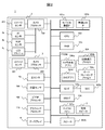
- FIG. 2 is a block diagram showing the configuration of the information device (camera) 1.
- the OUT camera 2 comprises an image sensor 201 and a camera processor 202.
- the AF sensor 2a supports an autofocus function
- the RGB sensor 2b supports an auto white balance function
- the LED flash 2c supports a flash function in a dark shooting environment.
- the RGB sensor 2b and the LED flash 2c are exclusively operable, and share one window on the back side where the OUT camera 2 is disposed as shown in FIG. 1 (b).
- the IN camera 3 includes an image sensor 301 and a camera processor 302, and is disposed on the front as shown in FIG. 1A, and is used mainly for the user's self-shooting of the information device 1.
- the light sensor 4a detects the ambient brightness to control the backlight of the display 4, and sets the display screen to be displayed to a brightness that is easy for the user to see.
- the position sensor 108 acquires position information of the information device 1 by GPS (Global Positioning System).
- the video processor 109 processes image data downloaded from the network and image data read out from the SDC (SD card) 105 b and sends the processed data to the graphic processor 110.
- the graphic processor 110 converts, in addition to the image data, HTML (Hyper Text Markup Language) data and the like processed by the CPU 102 into graphic data and causes the display 4 to display the data.
- HTML Hyper Text Markup Language
- the mobile communication interface (IF) 101a covers communication methods such as 3G and LTE (Long Term Evolution), and together with the wireless LAN interface (IF) 101b, a wireless network function suitable for downloading large-capacity data such as image data I will provide a.
- the wireless network may be of any other scheme.
- the CPU 102, the random access memory (RAM) 103, and the flash ROM (FROM) 104 play a central role in the arithmetic operation and program execution of the information device 1.
- the FROM 104 programs such as image and voice processing and an HTML browser are stored, expanded in the RAM 103 as necessary, and executed by the CPU 102. Images and HTML data are also temporarily stored in the RAM 103.
- the FROM 104 stores programs of the camera sharing application 104a and the SNS application 104d, which are features of the present embodiment. These programs are also expanded in the RAM 103 and executed by the CPU 102.
- the camera sharing application 104a defines an image communication process 104b that transmits and receives image data to and from the Internet 9 via the mobile communication IF 101a and the wireless LAN IF 101b, and auto framing that defines a framework for combining and displaying a plurality of camera images on the display 4 Process 104c is included.
- the SDIF 105a can store various data in the SDC (SD card) 105b. For example, by storing the image data captured by the OUT camera 2 and the IN camera 3 in the SDC 105 b in addition to the FROM 104, a large capacity can be stored.
- the USB IF 106 is an interface for connecting a USB device or receiving an external power supply.
- the microphone 107a and the receiving speaker 5 are used for voice communication, and the speaker 107b is used for listening to music data.
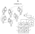
- FIG. 3 is a diagram showing the configuration of a camera image sharing system configured of a plurality of information devices 1 and a service providing device. It is assumed that a plurality of users 6 (A to F) who possess the information device (camera) 1 exist in a specific area 7 (for example, an event hall). Although it is assumed that each of the users A to F is registered in the camera image sharing service providing apparatus 13, the registration method is not limited. Each camera 1 uploads the captured image of the camera and the feature amount of the captured image to the camera image sharing service providing apparatus 13 via the Internet 9 each time the user 6 presses the shutter and shooting is performed. In the following, the case where the camera image sharing service providing apparatus 13 is used by focusing attention on the photographing operation of the user A is described.
- Each camera 1 and the Internet 9 are connected by a mobile communication base station or an access point 8 of a wireless LAN.
- the auto framing service providing apparatus 10 the camera image sharing service providing apparatus 13, and the SNS service providing apparatus 16 are connected to the Internet 9 (hereinafter, each “... Service providing apparatus” is simply referred to as “. Described as "service”.
- the camera image sharing service 13 has a user management database (DB) 14 and an image storage 15 for storing photographed image data of the camera and its feature quantity.
- the auto framing service 10 has a framing processing unit 11 and a framing table 12 in which the framing pattern generated by the framing processing unit 11 is described.
- the framing pattern describes display rules such as the arrangement and size of each image when combining a plurality of camera images.
- the auto framing service 10 is a service linked to the camera image sharing service 13.
- the camera image sharing service 13 and the auto framing service 10 are provided to the users registered in the user management DB 14 of the camera image sharing service 13, and camera images taken by a plurality of users are shared. It has become a system that supports combining (auto framing processing) the plurality of images suitably.
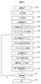
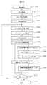
- FIG. 4A is a diagram showing an operation flow (S100) of the photographing process of the information device 1.
- S100 an operation flow of the photographing process of the information device 1.
- an image taken by the camera and an image of another camera to be combined with the image are selected and stored by the auto framing process.
- the user activates the OUT camera 2 or the IN camera 3 of the information device (camera) 1 (S101).
- the use of the OUT camera 2 is assumed for the purpose of sharing camera images of a plurality of cameras 1, but the IN camera 3 may be used.
- various settings of the camera auto focus, auto white balance, auto exposure, auto flash, default value setting of the number of imaging pixels, etc.
- S102 are automatically set.
- the camera setting is completed, the camera starts shooting and displays the shot image on the display 4 (S103). However, at this point in time, the user has not pressed the shutter.
- the user presses the camera image sharing service button (symbol 412 in FIG. 7A) to start the camera sharing application 104a and logs in to the camera image sharing service 13 (S104).
- the auto framing service 10 is also started at the same time, a part of the framing table 12 is downloaded, and the saved framing table 12 a is updated in the camera 1 (S 105).
- image data of another camera is downloaded from the camera image sharing service 13 (S106).
- the image data of other cameras to be downloaded is limited to only cameras suitable for sharing. That is, the camera is limited to cameras existing around the camera using the position information acquired by the position sensor 108. For example, a camera at a position close to a total of eight directions including front, rear, left, right and diagonal based on the camera. Select Furthermore, the shooting time is limited to only the latest image data captured within a predetermined time, going back from the current time. The image data of these other cameras are downloaded together with the feature quantities of the image.
- auto framing processing is performed by the auto framing process 104 c using the feature amounts of the image of the own camera and the images of the other cameras (S 108).
- a framing pattern is used as a display rule, such as which camera image is to be displayed at what position on the display 4 and in which size, or when multiple images are displayed one on top of the other.
- the graphic processor 110 creates a display screen in which the images of the own camera and another camera are combined, and displays the display screen on the display 4 (S109).
- the auto framing process (S108) will be described in detail with reference to FIGS.
- the user looks at the combined screen of a plurality of camera images displayed on the display 4, and selects another camera image to be combined with the own camera image (S110).
- the photographing process is performed, and the photographed image of the own camera is stored in the storage medium such as SDC 105b (S111) ).
- the selected other camera image is already downloaded and is not newly stored, but is linked to the image data of the own camera.
- the image data taken by the camera and the feature amount thereof, and the information of the framing pattern based on the image selection in S110 are uploaded to the camera image sharing service 13 (S112). These uploaded data are also used when a user of another camera uses the camera image sharing service 13.
- the user selects whether or not to continue shooting (S113), and when continuing, the process returns to S106, and the process is repeated from downloading of images of other cameras. In this way, as the position of the camera 1 moves and time passes, the images of the other cameras to be downloaded are updated as necessary. If already downloaded data is valid, it is not necessary to download duplicates.
- FIG. 4B is a diagram showing an operation flow (S120) of the reproduction process of the information device 1.
- the other camera image is combined with the photographed self-camera image, and is reproduced and displayed.
- the play button reference numeral 415 in FIG. 7B
- S121 the photographed and stored self-camera image and other camera images linked thereto are read from the storage medium (S122).
- An auto framing process is performed on these read out images by the auto framing process 104 c (S 123), and the composite screen is reproduced and displayed on the display 4 (S 124). Also, information on the framing pattern selected at the time of synthesis is uploaded (S125).
- the framing pattern is changed according to the user's instruction at the time of reproduction, for example, when an image other than the own camera image is preferentially displayed on the screen (S126), the auto framing process of S123 is performed. At S125, the information of the changed framing pattern is uploaded again.
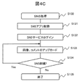
- FIG. 4C is a diagram showing an operation flow (S130) of the SNS process of the information device 1.
- the photographed image and the comment are uploaded using the SNS (Social Network Service) service 16.
- SNS Social Network Service
- the reproduction screen can be easily uploaded to the SNS. That is, the screen on which the auto framing process (S123) and the reproduction display of the composite screen (S124) are performed can be uploaded as it is (FIGS. 7C and 7D described later).
- S134 returns to S133 and uploads images, comments, etc. repeatedly.
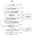
- FIG. 5 is a diagram showing an operation flow of the auto framing process (S140) of the information device 1, and corresponds to step S108 of FIG. 4A.
- S140 auto framing process
- auto framing processing (S140) is started.
- the self-camera continues shooting, and the captured image is refreshed at, for example, several frames to several tens of frames per second.
- An image of one frame is captured from among the images for which refreshing is continued (S141), and the feature amount is calculated on the captured image (S142).
- the feature amount downloaded from the camera image sharing service 13 in S106 is used (S143).
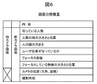
- FIG. 6 is a diagram showing an example of feature amounts of a camera image used for auto framing processing.
- a self-camera image the number of persons, the size and position of a group of people, the size of a human face, whether or not the user is visible, the focus distance, the position and size of the object being focused, etc. is there.
- the position of each camera in addition to these, the position of each camera (direction and distance from own camera), shooting time, etc. are added as feature amounts.
- a framing pattern is selected from the framing table 12a stored by the own camera based on the feature amounts of the own camera and the other cameras (S144).
- the method automatically selects a framing pattern having an index vector close to the index vector by a weighted distance from the framing table 12a using an index vector for search having a feature amount as an element.
- the framing table 12a is updated at S105 when the camera image sharing service 13 is started.
- the graphic processor 110 creates a display screen in which the images of a plurality of cameras including the own camera are synthesized (S145). The created composite screen is displayed on the display 4.
- FIG. 7A to 7F are examples of display screens of the information device (camera) 1.
- a display screen of the camera 1 owned by the user A is shown.
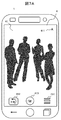
- FIG. 7A shows a display screen in the photographed image display state (S103) of FIG. 4A.
- the display 4 of the camera 1 displays a photographed image 41 of the camera of the user A, a user mark 411 indicating that the user is A, a camera image sharing service button 412, a shutter button 413, and a setting button 414.
- the user A presses the camera image sharing service button 412 to start login to the camera image sharing service 13.
- FIG. 7B shows the display state (S109) of the combined screen by the auto framing processing (S108) of FIG. 4A.
- the photographed image 41 of the user A's camera the photographed image 42 of the user B's camera, the photographed image 43 of the user C's camera, the photographed image 44 of the user D's camera, the photographed image 45 of the user E's camera, the user F A photographed image 46 of the camera of is displayed.
- the photographed images of these cameras are downloaded from the camera image sharing service 13 (S106 in FIG. 4A), and while the photographed image 41 of the camera A is an image at the current time, the other photographed images are slightly The shutter is pressed at the previous time and uploaded to the camera image sharing service 13.
- the respective user marks 421, 431, 441, 451, and 461 are displayed on each photographed image. Furthermore, selection buttons 422, 432, 442, 452, and 462 are displayed in each of the photographed images to select whether or not to associate the photographed image 41 of the user A (S110).
- the photographed image 41 of the user A and the photographed images 42 to 46 of the other users B to F in the same event can be viewed together, and the sense of reality of the event can be transmitted in an easy-to-understand manner Can.
- the photographed image 42 of the user B and the photographed image 43 of the user C are selected (linked) for combining, and when the user A presses the shutter button 413, the photographed image 41 of A is displayed.
- the feature amount is stored in the storage medium, and the captured image 42 of B, the captured image 43 of C, and the respective feature amounts are linked and stored (S111).
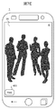
- FIG. 7C shows the display state (S124) of the combined screen by the auto framing processing (S123) at the time of reproduction in FIG. 4B.
- the auto framing process (S123) is performed on the photographed image 41 of the user A, the photographed image 42 of the user B linked to this, and the photographed image 43 of the user C.
- the photographed image 41 of the user A is displayed on the front in preference to other images.
- the SNS button 401 is pressed, the SNS application 104d is activated, and this screen can be uploaded.
- FIG. 7D shows the case where the framing pattern is changed in the state of FIG. 7C.
- it is a display screen after the user A taps the photographed image 42 of the user B, gives priority to the photographed image 42 of B, and executes the auto framing process again.
- the OUT camera of the user (user A) shoots the surroundings of the user, but does not necessarily shoot the user.
- another person's camera may be photographing itself (user A).
- the user A is in the photographed image 42 of B, and the user A taps the photographed image 42 of B to enlarge the photographed image 42 of B in which the user A is photographed. Is displayed on the front.
- FIG. 7E shows another case where the framing pattern is changed in the state of FIG. 7C.
- the photographed image 41 of the user A is tapped and enlarged and displayed on the entire screen.
- the display screens of FIGS. 7C to 7E can all be uploaded to the SNS service 16.
- the situation of the event site is communicated to other SNS users as a realistic image. Can.
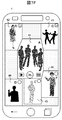
- FIG. 7F shows an example of a composite screen different from FIG. 7B.
- the images of the overlapping portions are obliquely cut and combined.
- the boundaries between the respective images are displayed uniformly, so that the region where the images overlap and disappear can not be biased to a specific image.
- an information device and an image sharing system in which selection of camera images to be synthesized is easy without requiring a special user operation. Can be provided. Furthermore, while being able to confirm the situation of a plurality of cameras at a glance by an event etc., it becomes possible to upload the screen which compounded a plurality of camera images to SNS, and to share a realistic image among users.
- FIG. 8 is a view showing an example of the user management database (DB) 14 of the camera image sharing service providing apparatus 13.
- the users registered in the user management DB 14 form a user group whose group name is “event T” in order to share or exchange camera images in advance.
- N users including "Sakura" are registered, and data of their user nickname, mobile number, IP address, password, and mail address are described.
- the information devices (cameras) used by these users need not be specific ones, and any information devices having a camera function and a display function can be used.
- the user can log in to the camera image sharing service 13 by entering an e-mail address and a password, and receive the provision of the service.
- FIG. 9 is a diagram showing an operation flow of the framing processing unit 11 in the auto framing service providing apparatus 10.
- the framing process S200
- the feature quantities of the camera image of the user are collected, and the index vectors are determined using the feature quantities of a plurality of camera images grouped (linked) as elements.
- a framing pattern suitable for combining and displaying a plurality of camera images is determined, and is registered in the framing table 12 in association with the index vector.
- the image data and the feature amount are uploaded and received from the camera 1 (S201)
- updating of the framing table 12 is started (S202).
- the uploaded feature amount is registered in the camera feature amount database 11a (S203).
- cameras (user B, C, D, E, F) located around the camera of user A in FIG. 3 are searched from the position information of the uploaded camera, and their feature values are The feature amount database 11a is read out (S204).
- framing pattern candidates are created using the read out feature amount (S205).
- the framing pattern is a display rule (such as arrangement and size) when combining each camera image, and is created based on the evaluation index of the framing pattern shown in FIG. 10 (S206). If the created candidate satisfies the evaluation index, it is additionally registered in the framing table 12 (S207), and the process is ended (S208). If the created candidate does not satisfy the evaluation index, the process returns to S205, the framing pattern candidate is corrected and re-created, and the evaluation is repeated.
- FIG. 10 is a diagram showing an example of the evaluation index of the framing pattern.
- the blank area where no camera image is displayed on the display 4 is made as small as possible, and the size is such that the central subject (for example, a person) appearing in each camera image is easily visible (for that reason, the camera Image enlargement / reduction, trimming is performed).
- the display according to the distance is made, specifically, the camera image close to the camera of A is relatively large and far camera image Is required to be displayed small. By satisfying these, it is possible to create a composite screen that reproduces the realism of the event venue.
- the information device 1 reduces the user operation for image composition. Further, the information device 1 can be reduced in size and weight.
- the information camera 1 handles the OUT camera 2 and the IN camera 3 at the same time, and performs an auto framing process on those images.
- the configuration of the information apparatus 1 (camera) is the same as the configuration shown in the first embodiment (FIG. 2), and the auto framing processing of the images of the OUT camera 2 and IN camera 3 is executed by the auto framing process 104 c stored in the FROM 104 Do.
- FIG. 11 is a diagram showing the imaging operation flow of the information device 1 in the third embodiment.
- the steps having the same functions as those in the operation flow (S100) of the first embodiment (FIG. 4A) are assigned the same numbers, and the steps different from the operation flow in FIG. 4A will be mainly described.
- the OUT camera 2 and the IN camera 3 are set (S102a).
- the feature amounts of the camera images of the OUT camera 2 and the IN camera 3 are calculated, and in the auto framing process (S108a), two camera images of the OUT camera 2 and the IN camera 3 are targeted I assume.
- the information device 1 includes a camera other than the OUT camera 2 and the IN camera 3, all camera images may be targeted.
- a screen obtained by combining the camera images of the OUT camera 2 and the IN camera 3 is displayed (S109). The user selects an image to be photographed from among them (S110a), and carries out photographing and storage (shutter pressing) (S111).
- the camera image sharing service 13 can be used, and the path is indicated by a broken line.
- Login is performed at an arbitrary timing (S104), the framing table 12 and camera images of other users are downloaded (S106), and auto framing processing (S108) is performed. This is photographed and stored, and camera image data, feature quantities, and further, a selected frame pattern are uploaded (S112).
- the reproduction process and the SNS process are the same as the operation flow of the first embodiment (FIGS. 4B and 4C).
- 12 to 14 show examples of display screens of the information device (camera) 1.
- 12A and 12B show the display state of the composite screen at the time of shooting, and correspond to step S109 in FIG.
- a framing pattern is used in which camera shooting is performed on the horizontal screen, and the image 48 of the OUT camera 2 and the image 47 of the IN camera 3 are arranged side by side in the horizontal direction (S108a).
- the selection button 482 is checked, and the image 48 of the OUT camera 2 is selected.
- a framing pattern is used in which a camera image is captured on the vertical screen, and the image 48 of the OUT camera 2 and the image 47 of the IN camera 3 are displayed side by side in the vertical direction.
- the selection buttons 482 and 472 are checked, and both the image 48 of the OUT camera 2 and the image 47 of the IN camera 3 are selected.
- the shutter button 413 is pressed in this state (S111)
- the images of both the OUT camera 2 and the IN camera 3 are shot and stored at the same time.
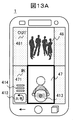
- FIGS. 13A to 13C are diagrams showing a method of selecting a camera image to be synthesized.
- the camera image is selected not by the selection button but by the shutter button 413, and the shutter button 413 is moved (dragged) to the position of the camera image to be selected.
- FIG. 13A shows that the shutter button 413 is moved onto the image 47 of the IN camera 3 and the outer frame of the image 47 is highlighted and selected by a thick line.
- the shutter button 413 is moved onto the image 48 of the OUT camera 2 to indicate that the image 48 is highlighted and selected.
- FIG. 13C the shutter button 413 is moved on the boundary between the image 48 and the image 47, the image 48 and the image 47 are highlighted, and the images of both the OUT camera 2 and the IN camera 3 are selected.
- a simple operation method of selecting an image to be shot and stored by the shutter button 413 is adopted. Furthermore, if the shutter button 413 is moved (dragged) so that the shutter is released when the finger is released from the shutter button 413, an operation of selecting a camera image and an operation of releasing the shutter are a series of user operations. It becomes possible, and the usability is further improved.
- FIG. 14A and FIG. 14B show a state in which a photographed and stored camera image is reproduced and displayed.
- the operation flow at the time of reproduction in FIG. 4B corresponds to the display of the combined screen (S124) after the auto framing processing (S123).
- the subject near the center of the camera image is displayed in close-up.
- FIG. 14A a framing pattern that equally treats the image 48 of the OUT camera 2 and the image 47 of the IN camera 3 is applied, whereas in FIG. 14B, the image 48 of the OUT camera 2 is mainly used.
- the framing pattern to be displayed is applied.
- the third embodiment it is possible to easily select a camera to be photographed without requiring a special user operation to obtain a display screen obtained by combining images of the OUT camera and the IN camera, and a camera image A shared system can be provided. Furthermore, it is also possible to provide a GUI (Graphical User Interface) in which the camera image selection operation and the shutter operation are seamless.
- GUI Graphic User Interface
- the functions and the like of the invention may be implemented by hardware, for example, by designing part or all of them with an integrated circuit.
- the program may be implemented by software by a microprocessor unit, a CPU or the like interpreting and executing an operation program for realizing each function and the like.
- the implementation range of software is not limited, and hardware and software may be used in combination.
- 1 Information equipment (camera), 2: OUT camera, 3: IN camera, 4: Display, 9: Internet, 10: Auto framing service providing device, 11: Framing processing unit, 12: Framing table, 13: Camera image sharing Service providing device 14: user management DB 15: image storage 16: SNS service providing device 101a: mobile communication IF 101b: wireless LAN IF 102: CPU 103: RAM 104: FROM 104a: camera sharing application , 104b: image communication process, 104c: auto framing process, 104d: SNS application, 105b: SDC, 108: position sensor, 109: video processor, 110: graphic processor.
Landscapes
- Engineering & Computer Science (AREA)
- Multimedia (AREA)
- Signal Processing (AREA)
- Computing Systems (AREA)
- Theoretical Computer Science (AREA)
- Studio Devices (AREA)
- Indication In Cameras, And Counting Of Exposures (AREA)
- Television Signal Processing For Recording (AREA)
- Closed-Circuit Television Systems (AREA)
Abstract
Description
図1は、実施例1に係る情報機器1の外観を示す図で、(a)は前面図、(b)は背面図である。情報機器1は、カメラ機能とディスプレイ機能を一体化した情報機器であって、例えば、スマートフォン、タブレットPCなどが相当する。その構成は、1aはリターン釦、1bはホーム釦、1cはマルチタスク釦、2はアウト(OUT)カメラ、2aはオートフォーカス(AF)センサ、2b/2cはRGBセンサ/LEDフラッシュ、3はイン(IN)カメラ、4はタッチセンサ一体型のディスプレイ、4aは光センサ、5は受話口である。背面側にあるアウト(OUT)カメラ2では外部の被写体を撮影し、前面側(ディスプレイ4側)にあるイン(IN)カメラ3では自撮りすることができる。以下、情報機器1のことを単に「カメラ」とも呼ぶことにする。
図4Aは、情報機器1の撮影処理の動作フロー(S100)を示す図である。この処理では、オートフレーミング処理により、自カメラの撮影画像とこれに合成する他カメラの画像を選択して保存する。
図7Aは、図4Aの撮影画像表示状態(S103)での表示画面を示す。カメラ1のディスプレイ4には、ユーザAのカメラの撮影画像41と、ユーザがAであることを示すユーザマーク411、カメラ画像共有サービス釦412、シャッタ釦413、設定釦414が表示されている。ユーザAは、カメラ画像共有サービス釦412を押すことで、カメラ画像共有サービス13へのログインを開始する。
図12Aと図12Bは、撮影時の合成画面の表示状態を示し、図11におけるステップS109に対応する。図12Aは、横画面でカメラ撮影を行い、OUTカメラ2の画像48とINカメラ3の画像47を横方向に並べて表示するフレーミングパターンが適用されている(S108a)。撮影画像の選択(S110a)では、選択釦482をチェックし、OUTカメラ2の画像48を選択している。
Claims (15)
- 第一のカメラとディスプレイを有する情報機器であって、
ネットワークを介して外部の第二のカメラの撮影画像をダウンロードする通信手段と、
前記第一のカメラの撮影画像と前記ダウンロードした前記第二のカメラの撮影画像を合成するフレーミング手段を備え、
前記合成した画面を前記ディスプレイに表示し、ユーザにより前記ディスプレイに表示された画面から前記第一のカメラの撮影画像に紐付けて表示する前記第二のカメラの撮影画像が選択されると、前記第一のカメラの撮影画像とともにどの撮影画像が選択されたかを示す紐付け情報をストレージ媒体に保存することを特徴とする情報機器。 - 請求項1に記載の情報機器であって、
前記通信手段は、前記第二のカメラの撮影画像とともに該撮影画像の特徴量をダウンロードし、
前記フレーミング手段は、前記第一のカメラの撮影画像の特徴量を算出し、該算出した特徴量と前記ダウンロードした前記第二のカメラの撮影画像の特徴量に基づいて、前記第一のカメラと前記第二のカメラの撮影画像を合成するためのフレーミングパターンを決定することを特徴とする情報機器。 - 請求項2に記載の情報機器であって、
前記通信手段は、撮影画像を合成するための複数のフレーミングパターンの集合をダウンロードし、
前記フレーミング手段は、前記ダウンロードしたフレーミングパターンの集合から前記特徴量に基づいて1つのフレーミングパターンを選択することを特徴とする情報機器。 - 請求項1に記載の情報機器であって、
前記通信手段が前記第二のカメラの撮影画像をダウンロードするとき、前記フレーミング手段は、前記第二のカメラの位置情報と撮影時刻情報によりダウンロードする撮影画像を限定することを特徴とする情報機器。 - 請求項1に記載の情報機器であって、
前記第一のカメラの撮影時に、該第一のカメラの撮影画像と、該撮影画像の特徴量及び位置情報を、前記通信手段により前記ネットワークにアップロードすることを特徴とする情報機器。 - 請求項1に記載の情報機器であって、
前記通信手段は、前記第二のカメラの撮影画像とともに該撮影画像の特徴量をダウンロードし、
前記フレーミング手段は、前記第一のカメラの撮影画像の特徴量を算出し、該算出した特徴量と前記紐付けされた前記第二のカメラの撮影画像の特徴量に基づいて、前記第一のカメラと前記第二のカメラの撮影画像を合成するためのフレーミングパターンを決定し、
該決定したフレーミングパターンに従い、前記第一のカメラの撮影画像と前記紐付けされた前記第二のカメラの撮影画像とを合成した画面を前記ディスプレイに表示することを特徴とする情報機器。 - 請求項2に記載の情報機器であって、
前記フレーミング手段で決定したフレーミングパターンの情報を、前記通信手段により前記ネットワークにアップロードすることを特徴とする情報機器。 - 請求項6に記載の情報機器であって、
前記ディスプレイに表示された合成画面に対し、ユーザが任意の撮影画像をタップすることで、前記フレーミング手段は前記フレーミングパターンの決定を変更することを特徴とする情報機器。 - 請求項1に記載の情報機器であって、
前記フレーミング手段は、前記ディスプレイに表示される複数の撮影画像がその境界で重なりを有する場合、各撮影画像の境界が均等に表示されるように各撮影画像の表示境界を変更することを特徴とする情報機器。 - 第一のカメラと第二のカメラとディスプレイを有する情報機器であって、
前記第一のカメラの撮影画像と前記第二のカメラの撮影画像を合成するフレーミング手段を備え、
前記合成した画面を前記ディスプレイに表示し、ユーザにより前記ディスプレイに表示された画面から前記第一のカメラと前記第二のカメラの撮影画像の少なくとも一方が選択されると、該選択された撮影画像をストレージ媒体に保存することを特徴とする情報機器。 - 請求項10に記載の情報機器であって、
前記フレーミング手段は、前記第一のカメラと前記第二のカメラの撮影画像の特徴量を算出し、該算出した特徴量に基づいて前記第一のカメラと前記第二のカメラの撮影画像を合成するためのフレーミングパターンを決定することを特徴とする情報機器。 - 請求項10に記載の情報機器であって、
前記ディスプレイに表示された画面から前記ストレージ媒体に保存する撮影画像を選択するために、ユーザは前記ディスプレイに表示されるシャッタ釦を所望の撮影画像の位置に移動させることを特徴とする情報機器。 - ネットワークを介し、カメラとディスプレイを有する複数の情報機器を、カメラ画像共有サービス提供装置と、オートフレーミングサービス提供装置に接続したカメラ画像共有システムにおいて、
前記カメラ画像共有サービス提供装置は、
前記複数の情報機器を管理するユーザ管理データベースと、
前記複数の情報機器からアップロードされた撮影画像及び該撮影画像の特徴量を保存する画像ストレージと、を備え、
前記オートフレーミングサービス提供装置は、
前記複数の情報機器からアップロードされた撮影画像の特徴量を用いて、複数の撮影画像を合成するためのフレーミングパターンを生成するフレーミング処理部と、
前記生成したフレーミングパターンを前記特徴量と対応付けて登録したフレーミングテーブルと、を備え、
前記情報機器は、
前記ネットワークを介して、前記カメラの撮影画像と該撮影画像の特徴量を、前記カメラ画像共有サービス提供装置にアップロードするとともに、前記カメラ画像共有サービス提供装置から他の情報機器の撮影画像と該撮影画像の特徴量、及び、前記オートフレーミングサービス提供装置から複数の撮影画像を合成するための複数のフレーミングパターンをダウンロードする通信手段と、
前記カメラの撮影画像の特徴量を算出し、該算出した特徴量と前記ダウンロードした前記他の情報機器の撮影画像の特徴量に基づいて、前記ダウンロードした複数のフレーミングパターンから1つのフレーミングパターンを選択して、前記カメラと前記他の情報機器の撮影画像を合成するフレーミング手段、を備え、
前記フレーミング手段で合成した前記カメラと前記他の情報機器の撮影画像を前記ディスプレイに表示することを特徴とするカメラ画像共有システム。 - 請求項13に記載のカメラ画像共有システムであって、
前記オートフレーミングサービス提供装置の前記フレーミング処理部は、合成される複数の撮影画像の位置関係、大きさ、合成画面に占める画像領域を評価指標としてフレーミングパターンを生成し、前記フレーミングテーブルに登録することを特徴とするカメラ画像共有システム。 - 請求項14に記載のカメラ画像共有システムであって、
前記オートフレーミングサービス提供装置の前記フレーミング処理部は、前記情報機器において選択されたフレーミングパターンの過去の選択実績を学習して、フレーミングパターンを生成することを特徴とするカメラ画像共有システム。
Priority Applications (6)
| Application Number | Priority Date | Filing Date | Title |
|---|---|---|---|
| PCT/JP2018/000713 WO2019138552A1 (ja) | 2018-01-12 | 2018-01-12 | 情報機器、及びカメラ画像共有システム |
| CN201880086195.2A CN111587570B (zh) | 2018-01-12 | 2018-01-12 | 信息设备、以及照相机图像共享系统 |
| US16/960,489 US12081910B2 (en) | 2018-01-12 | 2018-01-12 | Information device and camera image sharing system |
| JP2019564246A JP6886048B2 (ja) | 2018-01-12 | 2018-01-12 | 情報機器、及びカメラ画像共有システム |
| JP2021081702A JP7144571B2 (ja) | 2018-01-12 | 2021-05-13 | 情報機器、及びカメラ画像共有システム |
| US18/790,945 US20240414286A1 (en) | 2018-01-12 | 2024-07-31 | Information device and camera image sharing system |
Applications Claiming Priority (1)
| Application Number | Priority Date | Filing Date | Title |
|---|---|---|---|
| PCT/JP2018/000713 WO2019138552A1 (ja) | 2018-01-12 | 2018-01-12 | 情報機器、及びカメラ画像共有システム |
Related Child Applications (2)
| Application Number | Title | Priority Date | Filing Date |
|---|---|---|---|
| US16/960,489 A-371-Of-International US12081910B2 (en) | 2018-01-12 | 2018-01-12 | Information device and camera image sharing system |
| US18/790,945 Continuation US20240414286A1 (en) | 2018-01-12 | 2024-07-31 | Information device and camera image sharing system |
Publications (1)
| Publication Number | Publication Date |
|---|---|
| WO2019138552A1 true WO2019138552A1 (ja) | 2019-07-18 |
Family
ID=67219485
Family Applications (1)
| Application Number | Title | Priority Date | Filing Date |
|---|---|---|---|
| PCT/JP2018/000713 Ceased WO2019138552A1 (ja) | 2018-01-12 | 2018-01-12 | 情報機器、及びカメラ画像共有システム |
Country Status (4)
| Country | Link |
|---|---|
| US (2) | US12081910B2 (ja) |
| JP (2) | JP6886048B2 (ja) |
| CN (1) | CN111587570B (ja) |
| WO (1) | WO2019138552A1 (ja) |
Families Citing this family (7)
| Publication number | Priority date | Publication date | Assignee | Title |
|---|---|---|---|---|
| WO2021083146A1 (zh) | 2019-10-30 | 2021-05-06 | 北京字节跳动网络技术有限公司 | 视频处理方法、装置、终端及存储介质 |
| CN110784674B (zh) | 2019-10-30 | 2022-03-15 | 北京字节跳动网络技术有限公司 | 视频处理的方法、装置、终端及存储介质 |
| CN113068053A (zh) * | 2021-03-15 | 2021-07-02 | 北京字跳网络技术有限公司 | 一种直播间内的交互方法、装置、设备及存储介质 |
| CN117425057A (zh) * | 2022-07-07 | 2024-01-19 | 抖音视界(北京)有限公司 | 用于影像拍摄的方法、装置、设备和存储介质 |
| CN117407596A (zh) | 2022-07-07 | 2024-01-16 | 抖音视界(北京)有限公司 | 用于内容呈现的方法、装置、设备和存储介质 |
| CN115334246B (zh) | 2022-09-06 | 2025-07-01 | 抖音视界有限公司 | 用于影像拍摄的方法、装置、设备和存储介质 |
| US12535937B2 (en) * | 2022-12-12 | 2026-01-27 | Baker Hughes Holdings Llc | Merge menu directed inspections from multiple borescope inspections into a single inspection and report |
Citations (3)
| Publication number | Priority date | Publication date | Assignee | Title |
|---|---|---|---|---|
| JP2014212404A (ja) * | 2013-04-17 | 2014-11-13 | キヤノン株式会社 | 撮像装置及びその制御方法、プログラム、並びに記憶媒体 |
| JP2015069426A (ja) * | 2013-09-30 | 2015-04-13 | 富士フイルム株式会社 | 画像割当装置および画像割当方法 |
| US20150304588A1 (en) * | 2005-04-26 | 2015-10-22 | Searete Llc | Shared Image Devices |
Family Cites Families (12)
| Publication number | Priority date | Publication date | Assignee | Title |
|---|---|---|---|---|
| JP2008035246A (ja) * | 2006-07-28 | 2008-02-14 | Mitsubishi Space Software Kk | 構図評価装置、構図調整装置、画像撮影装置、構図評価プログラム、構図調整プログラム、画像撮影プログラム、構図評価方法、構図調整方法及び画像撮影方法 |
| JP2008219449A (ja) * | 2007-03-05 | 2008-09-18 | Fujifilm Corp | 撮像装置およびその制御方法 |
| JP5181806B2 (ja) * | 2008-04-25 | 2013-04-10 | 株式会社ニコン | 撮影装置 |
| US8947547B1 (en) * | 2010-09-12 | 2015-02-03 | Thomas Nathan Millikan | Context and content based automated image and media sharing |
| JP5773618B2 (ja) * | 2010-11-08 | 2015-09-02 | キヤノン株式会社 | 情報処理装置、情報処理装置の制御方法、プログラム |
| US20120179960A1 (en) * | 2011-01-07 | 2012-07-12 | Cok Ronald S | Image layout adjustment aparatus |
| JP5990068B2 (ja) | 2012-09-13 | 2016-09-07 | シャープ株式会社 | 制御装置、制御方法、および制御プログラム |
| JP2015011578A (ja) * | 2013-06-28 | 2015-01-19 | 株式会社東芝 | 情報処理装置および表示制御方法 |
| JP2016048835A (ja) | 2014-08-27 | 2016-04-07 | オリンパス株式会社 | 撮像装置、撮像装置の制御方法、撮像装置の制御プログラム、及び撮像システム |
| JP6529108B2 (ja) | 2014-10-14 | 2019-06-12 | オリンパス株式会社 | 画像処理装置、画像処理方法および画像処理プログラム |
| US20170147610A1 (en) * | 2015-11-24 | 2017-05-25 | Via Capitale | Image-based search engine |
| KR102422448B1 (ko) * | 2017-11-21 | 2022-07-19 | 삼성전자 주식회사 | 이미지와 관련된 링크 정보를 이용하여 외부 전자 장치와 이미지를 공유하는 방법 및 전자 장치 |
-
2018
- 2018-01-12 WO PCT/JP2018/000713 patent/WO2019138552A1/ja not_active Ceased
- 2018-01-12 CN CN201880086195.2A patent/CN111587570B/zh active Active
- 2018-01-12 US US16/960,489 patent/US12081910B2/en active Active
- 2018-01-12 JP JP2019564246A patent/JP6886048B2/ja active Active
-
2021
- 2021-05-13 JP JP2021081702A patent/JP7144571B2/ja active Active
-
2024
- 2024-07-31 US US18/790,945 patent/US20240414286A1/en active Pending
Patent Citations (3)
| Publication number | Priority date | Publication date | Assignee | Title |
|---|---|---|---|---|
| US20150304588A1 (en) * | 2005-04-26 | 2015-10-22 | Searete Llc | Shared Image Devices |
| JP2014212404A (ja) * | 2013-04-17 | 2014-11-13 | キヤノン株式会社 | 撮像装置及びその制御方法、プログラム、並びに記憶媒体 |
| JP2015069426A (ja) * | 2013-09-30 | 2015-04-13 | 富士フイルム株式会社 | 画像割当装置および画像割当方法 |
Also Published As
| Publication number | Publication date |
|---|---|
| JP2021132392A (ja) | 2021-09-09 |
| JPWO2019138552A1 (ja) | 2020-12-24 |
| US20210067741A1 (en) | 2021-03-04 |
| CN111587570B (zh) | 2025-08-12 |
| JP7144571B2 (ja) | 2022-09-29 |
| JP6886048B2 (ja) | 2021-06-16 |
| US20240414286A1 (en) | 2024-12-12 |
| US12081910B2 (en) | 2024-09-03 |
| CN111587570A (zh) | 2020-08-25 |
Similar Documents
| Publication | Publication Date | Title |
|---|---|---|
| JP7144571B2 (ja) | 情報機器、及びカメラ画像共有システム | |
| TW200931287A (en) | Guided photography based on image capturing device rendered user recommendations | |
| JP6375039B1 (ja) | プログラム、撮影方法及び端末 | |
| JP6635573B2 (ja) | 画像処理システム、画像処理方法、及びプログラム | |
| CN114009003B (zh) | 图像采集方法、装置、设备及存储介质 | |
| EP3764633B1 (en) | Photographing method, device, storage medium, and computer program | |
| US10192252B2 (en) | Information processing apparatus to provide position based services | |
| TW201741853A (zh) | 虛擬實境即時導覽方法及系統 | |
| CN113905175A (zh) | 视频生成方法、装置、电子设备及可读存储介质 | |
| JP2009129398A (ja) | 画像表示装置および画像表示方法 | |
| CN112887620A (zh) | 视频拍摄方法、装置及电子设备 | |
| JP6644288B1 (ja) | 体験共有システム、体験共有方法 | |
| CN114285988B (zh) | 显示方法、装置、电子设备及存储介质 | |
| CN115967854B (zh) | 拍照方法、装置及电子设备 | |
| JP7013786B2 (ja) | 情報処理装置、プログラム及び制御方法 | |
| CN115205169B (zh) | 图像处理方法、装置、电子设备和存储介质 | |
| JP6326656B2 (ja) | 画像提供システム | |
| CN116782022A (zh) | 一种拍摄方法、装置、电子设备及可读存储介质 | |
| JP2017134403A (ja) | 写真シール遊戯システム | |
| WO2023021759A1 (ja) | 情報処理装置、情報処理方法 | |
| CN116828131A (zh) | 基于虚拟现实的拍摄处理方法、装置及电子设备 | |
| CN120255744B (zh) | 多媒体资源发布方法、装置、电子设备及存储介质 | |
| KR102540516B1 (ko) | AR(Augmented Reality) 컨텐츠를 제공하는 장치, 사용자 단말 및 방법 | |
| JP2016092727A (ja) | アドバイス表示装置 | |
| CN114500846B (zh) | 现场活动观看视角切换方法、装置、设备及可读存储介质 |
Legal Events
| Date | Code | Title | Description |
|---|---|---|---|
| 121 | Ep: the epo has been informed by wipo that ep was designated in this application |
Ref document number: 18899980 Country of ref document: EP Kind code of ref document: A1 |
|
| ENP | Entry into the national phase |
Ref document number: 2019564246 Country of ref document: JP Kind code of ref document: A |
|
| NENP | Non-entry into the national phase |
Ref country code: DE |
|
| 122 | Ep: pct application non-entry in european phase |
Ref document number: 18899980 Country of ref document: EP Kind code of ref document: A1 |
|
| WWG | Wipo information: grant in national office |
Ref document number: 201880086195.2 Country of ref document: CN |