WO2019138508A1 - 超音波診断装置及び超音波診断システム - Google Patents
超音波診断装置及び超音波診断システム Download PDFInfo
- Publication number
- WO2019138508A1 WO2019138508A1 PCT/JP2018/000515 JP2018000515W WO2019138508A1 WO 2019138508 A1 WO2019138508 A1 WO 2019138508A1 JP 2018000515 W JP2018000515 W JP 2018000515W WO 2019138508 A1 WO2019138508 A1 WO 2019138508A1
- Authority
- WO
- WIPO (PCT)
- Prior art keywords
- transducers
- ultrasonic
- output
- unit
- ultrasound
- Prior art date
- Legal status (The legal status is an assumption and is not a legal conclusion. Google has not performed a legal analysis and makes no representation as to the accuracy of the status listed.)
- Ceased
Links
Images




Classifications
-
- A—HUMAN NECESSITIES
- A61—MEDICAL OR VETERINARY SCIENCE; HYGIENE
- A61B—DIAGNOSIS; SURGERY; IDENTIFICATION
- A61B8/00—Diagnosis using ultrasonic, sonic or infrasonic waves
- A61B8/52—Devices using data or image processing specially adapted for diagnosis using ultrasonic, sonic or infrasonic waves
- A61B8/5207—Devices using data or image processing specially adapted for diagnosis using ultrasonic, sonic or infrasonic waves involving processing of raw data to produce diagnostic data, e.g. for generating an image
-
- A—HUMAN NECESSITIES
- A61—MEDICAL OR VETERINARY SCIENCE; HYGIENE
- A61B—DIAGNOSIS; SURGERY; IDENTIFICATION
- A61B8/00—Diagnosis using ultrasonic, sonic or infrasonic waves
- A61B8/54—Control of the diagnostic device
-
- A—HUMAN NECESSITIES
- A61—MEDICAL OR VETERINARY SCIENCE; HYGIENE
- A61B—DIAGNOSIS; SURGERY; IDENTIFICATION
- A61B8/00—Diagnosis using ultrasonic, sonic or infrasonic waves
- A61B8/44—Constructional features of the ultrasonic, sonic or infrasonic diagnostic device
- A61B8/4444—Constructional features of the ultrasonic, sonic or infrasonic diagnostic device related to the probe
-
- A—HUMAN NECESSITIES
- A61—MEDICAL OR VETERINARY SCIENCE; HYGIENE
- A61B—DIAGNOSIS; SURGERY; IDENTIFICATION
- A61B8/00—Diagnosis using ultrasonic, sonic or infrasonic waves
- A61B8/44—Constructional features of the ultrasonic, sonic or infrasonic diagnostic device
- A61B8/4444—Constructional features of the ultrasonic, sonic or infrasonic diagnostic device related to the probe
- A61B8/4461—Features of the scanning mechanism, e.g. for moving the transducer within the housing of the probe
-
- G—PHYSICS
- G01—MEASURING; TESTING
- G01S—RADIO DIRECTION-FINDING; RADIO NAVIGATION; DETERMINING DISTANCE OR VELOCITY BY USE OF RADIO WAVES; LOCATING OR PRESENCE-DETECTING BY USE OF THE REFLECTION OR RERADIATION OF RADIO WAVES; ANALOGOUS ARRANGEMENTS USING OTHER WAVES
- G01S15/00—Systems using the reflection or reradiation of acoustic waves, e.g. sonar systems
- G01S15/88—Sonar systems specially adapted for specific applications
- G01S15/89—Sonar systems specially adapted for specific applications for mapping or imaging
- G01S15/8906—Short-range imaging systems; Acoustic microscope systems using pulse-echo techniques
- G01S15/8909—Short-range imaging systems; Acoustic microscope systems using pulse-echo techniques using a static transducer configuration
- G01S15/8915—Short-range imaging systems; Acoustic microscope systems using pulse-echo techniques using a static transducer configuration using a transducer array
- G01S15/8927—Short-range imaging systems; Acoustic microscope systems using pulse-echo techniques using a static transducer configuration using a transducer array using simultaneously or sequentially two or more subarrays or subapertures
-
- G—PHYSICS
- G01—MEASURING; TESTING
- G01S—RADIO DIRECTION-FINDING; RADIO NAVIGATION; DETERMINING DISTANCE OR VELOCITY BY USE OF RADIO WAVES; LOCATING OR PRESENCE-DETECTING BY USE OF THE REFLECTION OR RERADIATION OF RADIO WAVES; ANALOGOUS ARRANGEMENTS USING OTHER WAVES
- G01S7/00—Details of systems according to groups G01S13/00, G01S15/00, G01S17/00
- G01S7/52—Details of systems according to groups G01S13/00, G01S15/00, G01S17/00 of systems according to group G01S15/00
- G01S7/52017—Details of systems according to groups G01S13/00, G01S15/00, G01S17/00 of systems according to group G01S15/00 particularly adapted to short-range imaging
- G01S7/52019—Details of transmitters
- G01S7/5202—Details of transmitters for pulse systems
-
- G—PHYSICS
- G01—MEASURING; TESTING
- G01S—RADIO DIRECTION-FINDING; RADIO NAVIGATION; DETERMINING DISTANCE OR VELOCITY BY USE OF RADIO WAVES; LOCATING OR PRESENCE-DETECTING BY USE OF THE REFLECTION OR RERADIATION OF RADIO WAVES; ANALOGOUS ARRANGEMENTS USING OTHER WAVES
- G01S7/00—Details of systems according to groups G01S13/00, G01S15/00, G01S17/00
- G01S7/52—Details of systems according to groups G01S13/00, G01S15/00, G01S17/00 of systems according to group G01S15/00
- G01S7/52017—Details of systems according to groups G01S13/00, G01S15/00, G01S17/00 of systems according to group G01S15/00 particularly adapted to short-range imaging
- G01S7/52085—Details related to the ultrasound signal acquisition, e.g. scan sequences
-
- G—PHYSICS
- G01—MEASURING; TESTING
- G01S—RADIO DIRECTION-FINDING; RADIO NAVIGATION; DETERMINING DISTANCE OR VELOCITY BY USE OF RADIO WAVES; LOCATING OR PRESENCE-DETECTING BY USE OF THE REFLECTION OR RERADIATION OF RADIO WAVES; ANALOGOUS ARRANGEMENTS USING OTHER WAVES
- G01S7/00—Details of systems according to groups G01S13/00, G01S15/00, G01S17/00
- G01S7/52—Details of systems according to groups G01S13/00, G01S15/00, G01S17/00 of systems according to group G01S15/00
- G01S7/52017—Details of systems according to groups G01S13/00, G01S15/00, G01S17/00 of systems according to group G01S15/00 particularly adapted to short-range imaging
- G01S7/52096—Details of systems according to groups G01S13/00, G01S15/00, G01S17/00 of systems according to group G01S15/00 particularly adapted to short-range imaging related to power management, e.g. saving power or prolonging life of electronic components
Definitions
- the present invention relates to an ultrasonic diagnostic apparatus and an ultrasonic diagnostic system.
- mobile-type ultrasonic diagnostic apparatuses for example, one having a configuration for performing processing for obtaining an ultrasonic image is entirely incorporated in the ultrasonic diagnostic apparatus is known.
- power consumption is reduced by, for example, reducing the number of channels of the probe.
- the technology disclosed herein has been made in view of the above circumstances, and aims to reduce power consumption while maintaining image quality.
- a probe for transmitting an ultrasonic wave toward a living body and receiving an ultrasonic wave reflected by the living body, and a first one of a plurality of transducers of the probe in a moving image mode Ultrasound image data based on ultrasound received by the number of transducers is output, and ultrasound image data based on ultrasound received by the second number of transducers greater than the first number in the still image mode
- a control unit for outputting a signal a control unit for outputting a signal.
- Power consumption can be reduced while maintaining image quality.
- FIG. 1 is a diagram showing the configuration of the ultrasound diagnostic system according to the first embodiment.
- the ultrasound diagnostic system 100 includes an ultrasound diagnostic apparatus 200 and a terminal device 300.
- the ultrasonic diagnostic apparatus 200 and the control apparatus 300 perform wireless communication.
- the ultrasound diagnostic apparatus 200 of the present embodiment includes an ultrasound image acquisition unit 210 including a probe 230, and a main body 220.
- the ultrasound image acquisition unit 210 of the present embodiment has a probe 230 and an image processing unit 240.
- the probe 230 has a transducer array 231 in which a plurality of transducers are arranged in an array.
- the probe 230 according to the present embodiment transmits ultrasonic waves and switches reflected ultrasonic waves reflected by the living body by sequentially switching the transducers selected as the transmission aperture and the reception aperture in the transducer array 231. Receive and do. The details of the probe 230 will be described later.
- the image processing unit 240 includes a control unit 241, a pulser switch unit 242, an AMP (amplifier), an ADC (analog to digital converter) unit 243, and a digital signal processing unit 244, and transmits an ultrasonic wave from the probe 230.
- the ultrasound image data based on the reflected wave (ultrasound) received by the probe 230 is generated and output to the main body 220.
- the control unit 241 controls the entire ultrasonic diagnostic apparatus 200.
- the control unit 241 is also connected to the connector 247 by I 2 C (I-squared-C) or the like.
- I 2 C I-squared-C
- the signal output from the main body unit 220 is input to the control unit 241 via the connector 247.
- control unit 241 causes the AMP / ADC unit 243 to convert the number of channels to be converted into digital signals in response to an operation of starting measurement or an operation of stopping measurement on the ultrasonic diagnostic apparatus 200. change. The details of the control unit 241 will be described later.
- the pulser switch unit 242 selects the probe 230 by the switch unit, transmits a pulse signal to the probe 230, and irradiates the living body P with ultrasonic waves from the probe 230.
- the living body P When the living body P is irradiated with ultrasonic waves, the living body P reflects the ultrasonic waves at boundaries where acoustic impedances are different.
- the reflected wave reflected from the living body P is received by the probe 230, and is output to the AMP / ADC unit 243 selected by the switch unit of the pulsar switch unit 242.
- the AMP • ADC unit 243 amplifies the reflected wave of the ultrasonic wave output from the pulsar switch unit 242 by an amplifier (AMP), converts it into a digital signal by the ADC, and outputs the digital signal to the digital signal processing unit 244.
- AMP amplifier
- the digital signal processing unit 244 performs various types of processing on the digital signal output from the AMP / ADC unit 243, acquires ultrasound image data, and outputs the ultrasound image data to the main unit 220 via the connector 247.
- the processing performed by the digital signal processing unit 244 is processing for equalizing the delay from the timing when the reflected wave is output from the pulsar switch unit 242, averaging (phasing addition) processing, in the living body P And gain correction processing in consideration of the attenuation of the image, envelope processing for extracting luminance information, and the like.
- the digital signal processing unit 244 is connected to the connector 247 by SPI (Serial Peripheral Interface) or the like, and transmits ultrasound image data to the main unit 220 by SPI.
- SPI Serial Peripheral Interface
- the main body unit 220 of the present embodiment includes a communication unit 221 and a power supply unit 222, and is connected to the ultrasound image acquisition unit 210 via the connector 247.
- the communication unit 221 communicates with the terminal device 300. Specifically, the communication unit 221 performs, for example, wireless communication with the terminal device 300 according to the standard such as Wi-Fi.
- the standard used for wireless communication is not limited to Wi-Fi, and may be another standard.
- the communication unit 221 is connected to the connector 247 and receives a signal transmitted from the terminal device 300. Specifically, the communication unit 221 receives, for example, an irradiation instruction of ultrasonic waves from the terminal device 300.
- the communication unit 221 of the present embodiment transmits the signal output from the ultrasound image acquisition unit 210 to the terminal device 300. Specifically, the communication unit 221 transmits ultrasound image data to the terminal device 300.
- the power supply unit 222 is, for example, a chargeable and dischargeable secondary battery or the like, and supplies power to each unit of the ultrasonic diagnostic apparatus 200.
- the ultrasound image data is digitized by the ultrasound image acquisition unit 210 and then output to the main unit 220 as a digital signal.
- ultrasound image data to be delivered between the ultrasound image acquisition unit 210 and the main body unit 220 is a digital signal (digital data).
- the terminal device 300 of the present embodiment includes a central processing unit (CPU) 310, a communication unit 311, a memory 312, and a display 313.
- CPU central processing unit
- the CPU 310 controls the overall operation of the terminal device 300.
- the communication unit 311 receives a signal transmitted from the ultrasound diagnostic apparatus 200. Specifically, the communication unit 311 receives ultrasonic image data transmitted from the ultrasonic diagnostic apparatus 200.
- the memory 312 stores ultrasonic image data received by the communication unit 311, data as a result of calculation by the CPU 310, and the like.
- the display 313 displays ultrasonic image data and the like received from the ultrasonic diagnostic apparatus 200.
- ultrasound image data displayed on the display 313 ultrasound image data of a moving image acquired during scanning of the living body P by the ultrasound diagnostic apparatus 200 and scanning of the living body P by the ultrasound diagnostic apparatus 200 is stopped Image data of a still image acquired when the
- the terminal device 300 of the present embodiment may be, for example, a tablet-type terminal device, and in that case, the display 313 includes a touch panel or the like.
- ultrasound image data is transmitted from the ultrasound diagnostic apparatus 200 to the terminal device 300 by wireless communication. Therefore, according to the present embodiment, when causing the living body P to scan the ultrasonic diagnostic apparatus 200, the movement of the operator of the ultrasonic diagnostic apparatus 200 is not limited by the communication cable or the like.
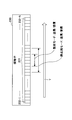
- FIG. 2 is a view for explaining the probe of the first embodiment.
- the probe 230 of the present embodiment has a transducer array 231.
- the transducer array 231 has N transducers 232-1 to 232-N arranged in a line.
- the transmission aperture and the reception aperture are moved on the transducer array 231 to realize the scanning of the living body P by the ultrasonic waves.
- the probe 230 selects a predetermined number of transducers 232 from the transducers 232-1 at the left end as the transmission aperture and the reception aperture, and selects the predetermined number
- the oscillators 232 of the above may be switched sequentially to the oscillators 232-N.
- the vibrator 232 serving as the transmission aperture also serves as the reception aperture. That is, in this embodiment, when the transducers 232 as transmission apertures output ultrasonic waves, these transducers 232 receive reflection waves as reception apertures and output a signal generated based on the reflection waves. .
- the ultrasonic diagnostic apparatus 200 of the present embodiment while the scanning of the living body P by the probe 230 is being performed, a part of the signals output from the transducer 232 serving as the receiving aperture is used. Acquire a sound wave image. Further, in the present embodiment, when the scanning of the living body P by the probe 230 is stopped, an ultrasonic image based on the signals output from all the transducers 232 serving as the receiving aperture is acquired.
- the ultrasound image output from the ultrasound diagnostic apparatus 200 is a moving image according to the scan.
- the ultrasonic image output from the ultrasonic diagnostic apparatus 200 is a still image.
- the operation mode of the ultrasonic diagnostic apparatus 200 while the scanning of the living body P by the probe 230 is performed is referred to as a moving image mode, and the scanning of the living body P by the probe 230 is stopped.
- the operation mode of the ultrasonic diagnostic apparatus 200 in the case where the error occurs is called a still image mode.
- acquiring ultrasonic images (moving images) with the ultrasonic diagnostic apparatus 200 in the moving image mode is synonymous with scanning the living body P with ultrasonic waves
- the ultrasonic diagnostic apparatus 200 in the still image mode Acquiring an ultrasound image (still image) is synonymous with stopping the scanning (measurement) of the living body P.
- the first number is smaller than the number (second number) of the transducers 232 serving as the reception aperture.
- the first number in the moving image mode is four, and the second number in the still image mode is eight.
- the signal used for generating the ultrasonic image is selected from the signal output from the transducer 232 set as the reception aperture, thereby obtaining the still image mode. It is possible to maintain the image quality of the ultrasound image to be processed and to reduce the power consumption when operating in the moving image mode.
- the number of transducers 232 serving as the transmission aperture and the reception aperture is eight in both the moving image mode and the still image mode.
- the signals output from the four transducers 232 arranged in the central portion are selected.
- control unit 241, the AMP / ADC unit 243, and the digital signal processing unit 244 according to the present embodiment will be described.
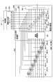
- FIG. 3 is a diagram for explaining the control unit, the AMP / ADC unit, and the digital signal processing unit according to the first embodiment.
- the control unit 241 of the present embodiment has a coefficient generation unit 250.
- the control unit 241 causes the coefficient generation unit 250 to generate the coefficient signal S12 for selecting the signal generated by the vibrator 232 serving as the reception aperture based on the signal S11 indicating the start or stop of the scan, and the AMP ⁇ ADC unit 243 and to the digital signal processing unit 244.
- the coefficient signal S12 is a binary signal and is a signal including the coefficients S1 to S8 corresponding to the vibrator 232 serving as the transmission aperture and the reception aperture.
- the number of transducers 232 serving as the transmission aperture and the reception aperture is eight.
- the coefficient S1 and the coefficient S8 correspond to both ends of the eight transducers 232 selected as the transmission aperture and the reception aperture, and the coefficient S4 and the coefficient S5 are positioned at the central portion in the array of the transducers 232 selected Corresponding to the vibrator 232.
- the AMP ⁇ ADC unit 243 includes AMP ⁇ ADC units 243-1 to AMP ⁇ ADC units 243-8 corresponding to the coefficients S1 to S8 of the coefficient signal S12, and the AMP ⁇ ADC units 243-1 to AMP ⁇ ADC units 243 The values of the coefficients S1 to S8 are input for each of -8.
- the AMP / ADC unit 243 supplies power to the AMP / ADC unit 243 corresponding to the coefficient Sn having a value of “1”, amplifies the signal output from the vibrator 232, and digitally converts the signal. It converts into a signal and outputs it to the digital signal processing unit 244.
- a signal output from the transducer 232 corresponding to the coefficient Sn having a value of “1” is selected among the coefficients S1 to S8 to generate an ultrasound image.
- the digital signal processing unit 244 includes a delay adjustment unit 251 and a phasing addition unit 252.
- the delay adjustment unit 251 synchronizes the ultrasonic image data converted into the digital signal by the AMP / ADC unit 243.
- the phasing addition unit 252 includes multipliers 253-1 to 253-8 corresponding to the coefficients S1 to S8 of the coefficient signal S12, and an adder 254.
- the multipliers 253-1 to 253-8 multiply the signal output from the delay adjustment unit 251 by the coefficient Sn corresponding to each of the multipliers 253-n.
- the adder 254 adds the results multiplied by the multiplier 253-n.
- the value output from the AMP / ADC unit 243 is input to the multiplier 253 corresponding to the coefficient Sn having a value of “1”, and is multiplied by the coefficient Sn. Further, in the digital signal processing unit 244, the signal from the AMP / ADC unit 243 is not input to the multiplier 253 corresponding to the coefficient Sn having a value of “0”, and becomes invalid.
- ultrasound image data generated based on the signal output from the transducer 232 corresponding to the coefficient Sn having a value of “1” is output in the coefficient signal S12.
- the control unit 241 of the present embodiment When the signal S11 indicates the start of scanning, the control unit 241 of the present embodiment generates the coefficient signal S12 in which four coefficients among the coefficients S1 to S8 are “1” because the moving image mode is set. , And output to the AMP / ADC unit 243 and the digital signal processing unit 244.
- the coefficient Sn corresponding to the vibrator 232 located at the central portion of the eight vibrators 232 be “1”. Specifically, it is preferable to set the coefficients S3 to S6 to "1" and the coefficients S1, S2, S7, and S8 to "0".
- the AMP / ADC unit 243 supplies power only to the AMP / ADC units 243-3 to 243-6, and converts the signal input from the pulser switch unit 242 into a digital signal. , And output to the digital signal processing unit 244.
- the adder 254 adds the multiplication results of the multipliers 253-3 to 253-6 and outputs the result as ultrasound image data. That is, here, ultrasound image data based on the signals output from the four transducers 232 is output.
- control unit 241 since the control unit 241 is in the still image mode when the signal S11 indicates the stop of scanning, the control unit 241 generates the coefficient signal S12 in which all the coefficients S1 to S8 are “1”, and the AMP ⁇ ADC unit 243 and the digital signal processing unit 244.
- the coefficient signal S12 When the coefficient signal S12 is input to the AMP / ADC unit 243, power is supplied to the AMP / ADC units 243-1 to 243-8.
- the AMP ⁇ ADC units 243-1 to 243-8 convert the signals input from the lucer switch unit 242 into digital signals, and output the digital signals to the digital signal processing unit 244.
- the digital signal processing unit 244 inputs “1” to the multipliers 253-1 to 253-8. Therefore, the adder 254 adds the multiplication results of the multipliers 253-1 to 253-8, and outputs the result as ultrasound image data. That is, here, ultrasound image data based on the signals output from the eight transducers 232 is output.
- control unit 241 of the present embodiment After generating the coefficient signal S12 in which all of the coefficients S1 to S8 are “1”, the control unit 241 of the present embodiment generates the coefficient signal S12 in which all the coefficients S1 to S8 are “0”. Output.
- the AMP ⁇ ADC unit 243 shuts off the supply of power to the AMP ⁇ ADC units 243-1 to 243-8 when the coefficient signal S12 having all the coefficients S1 to S8 of “0” is input. Therefore, no digital signal is output from the AMP / ADC unit 243. That is, in the present embodiment, ultrasound image data is not acquired after the ultrasound diagnostic apparatus 200 is set to the still image mode.
- водем ⁇ (second number) transducers 232 are output only when the scanning of the living body P by the ultrasonic diagnostic apparatus 200 is stopped to acquire an ultrasonic image. Acquire an ultrasound image based on the signal. Therefore, according to the present embodiment, the image quality of the still image can be improved as compared with the ultrasonic image during scanning.
- ultrasound image data is acquired based on signals output from the four transducers 232 arranged in the central portion of the transducers 232 serving as the transmission aperture and the reception aperture. For this reason, according to the present embodiment, a signal output from the transducer 232 that receives an ultrasonic wave (reflected wave) having a large signal level is selected, and a relatively good ultrasonic image can be obtained even in the moving image mode. It can be acquired.
- AMP / ADC units 243 are operated during scanning of the ultrasound diagnostic apparatus 200, so power consumption can be reduced.
- the ultrasound diagnostic apparatus 200 of the present embodiment is acquired based on ultrasound signals received by the first number of transducers among the plurality of transducers of the probe 230.
- the ultrasound image data is output to the terminal device 300.
- the ultrasonic diagnostic apparatus 200 according to the present embodiment uses a second number of transducers, which is larger than the first number, among the plurality of transducers included in the probe 230.
- the ultrasound image data acquired based on the received ultrasound signal is output to the terminal device 300.
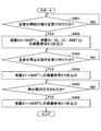
- FIG. 4 is a flowchart for explaining the operation of the control unit of the ultrasonic diagnostic apparatus according to the first embodiment.
- the control unit 241 of the present embodiment determines whether or not an instruction to start scanning of a subject with an ultrasound image has been received from the ultrasound diagnostic apparatus 200 (step S401). In other words, the control unit 241 of the present embodiment determines whether or not the signal S11 indicates the start of scanning.
- a button or the like for instructing the start / stop of the scan may be provided on the case, and the start / stop of the scan may be performed each time the button is pressed.
- a signal S11 may be input to the control unit 241.
- step S401 when the instruction to start the scan is not received, the control unit 241 waits until the instruction is received.
- step S401 when an instruction to start scanning is received, the control unit 241 causes the coefficient generation unit 250 to set the values of the coefficients S3 to S6 to "1" and the values of the coefficients S1, S2, S7, and S8 to "0.”
- the coefficient signal S12 is generated and output to the AMP / ADC unit 243 and the digital signal processing unit 244 (step S402).
- control unit 241 determines whether an instruction to stop the scan has been received (step S403). In other words, the control unit 241 determines whether or not the signal S11 indicating stop of scanning is input.
- step S403 when the instruction to stop the scan is not received, the control unit 241 waits until the instruction is received. In step S403, when an instruction to stop scanning is received, the control unit 241 causes the coefficient generation unit 250 to generate a coefficient signal S12 in which the values of the coefficients S1 to S8 are “1”, and the AMP ⁇ ADC unit 243, It is output to the digital signal processing unit 244 (step S404).
- step S405 the control unit 241 determines whether ultrasound image data of a still image is output to the terminal device 300.
- step S405 when the ultrasound image data is not output, the control unit 241 stands by until the ultrasound image data is output.
- control unit 241 causes the coefficient generation unit 250 to generate a coefficient signal S12 in which the values of the coefficients S1 to S8 are "0", and the AMP ⁇ ADC unit 243, It outputs to the digital signal processing unit 244 (step S406), and ends the processing.
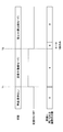
- FIG. 5 is a timing chart for explaining the operation of the ultrasonic diagnostic apparatus of the first embodiment.
- FIG. 5 shows the relationship between the state of the ultrasound diagnostic system 100, the start / stop of the scan, and the number of channels used.
- the ultrasound diagnostic system 100 when the scan of the living body P is not performed by ultrasound, ultrasound is not transmitted, and the number of transducers 232 used for receiving a reflected wave is 0. .
- the state of the ultrasonic diagnostic system 100 is during scanning (during measurement).
- the ultrasonic diagnostic apparatus 200 acquires ultrasonic image data in the moving image mode, and causes the display 313 of the terminal device 300 to display ultrasonic moving image data.
- a state after the ultrasonic diagnostic system 100 receives an instruction to start scanning of the living body P by the ultrasonic diagnostic apparatus 200 and receives an instruction to stop scanning the living body P.
- the ultrasound diagnostic apparatus 200 acquires ultrasound image data based on the signals output from the four transducers 232.
- the ultrasound diagnostic apparatus 200 outputs ultrasound image data of a still image acquired based on the signals output from the eight transducers 232 to the terminal device 300.
- the ultrasound image data of the still image output here is ultrasound image data of one ultrasound image of the still image.
- the still image mode of the present embodiment shows a state in which an ultrasonic image of a still image is displayed on the display 313 of the terminal device 300 after receiving an instruction to stop scanning of the living body P.
- the ultrasonic diagnostic apparatus 200 stops the acquisition of the ultrasonic image.
- the state of the ultrasonic diagnostic system 100 is in a state where acquisition of a new ultrasonic image is stopped. .
- power consumption can be reduced while maintaining the image quality of an ultrasound image acquired as a still image.
- transducers 232 serving as the transmission aperture and the reception aperture are used.
- the present invention is not limited to this.
- the number of transducers 232 serving as the transmission aperture and the reception aperture may be thirty two.
- the power consumption of the entire device is reduced. It could be reduced from 2W to about 0.75W.
- the second embodiment will be described below with reference to the drawings.
- the second embodiment is different from the first embodiment in that ultrasonic image data is periodically acquired using signals output from eight transducers 232 in the moving image mode. Therefore, in the following description of the second embodiment, components having the same functional configuration as the first embodiment are given the same reference numerals as the symbols used in the description of the first embodiment, and the description thereof Omit.
- the control unit 241 sets 8 for each predetermined time or for each predetermined frame of ultrasonic image data acquired as a moving image during scanning of the living body P by the ultrasonic diagnostic apparatus 200 (moving image mode). Ultrasonic image data is acquired based on the signals output from the two transducers 232.
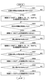
- FIG. 6 is a flowchart for explaining the operation of the control unit of the ultrasonic diagnostic apparatus according to the second embodiment.
- step S601 and step S602 in FIG. 6 are the same as the processes in step S401 and step S402 in FIG.
- step S603 the control unit 241 determines whether a predetermined interval (time) has elapsed (step S603). In step S603, when the predetermined interval has not elapsed, the control unit 241 stands by until the predetermined interval elapses.
- the predetermined interval may be, for example, a time for acquiring 10 frames of ultrasonic image data.
- step S603 when a predetermined interval has elapsed, the control unit 241 generates a coefficient signal S12 in which the values of the coefficients S1 to S8 are “1”, and notifies the AMP ⁇ ADC unit 243 and the digital signal processing unit 244. (Step S604).
- the control unit 241 determines whether or not ultrasound image data is output based on the signals output from the eight transducers 232 (step S605).
- the ultrasound image data output here is ultrasound image data of an ultrasound image of one still image.
- step S605 when the ultrasound image data is not output, the control unit 241 waits until the ultrasound image data is output.
- step S605 When ultrasound image data is output in step S605, the control unit 241 proceeds to step S606.
- step S606 to step S610 is the same as the processing from step S402 to step S406 in FIG.
- the third embodiment will be described below with reference to the drawings.
- the third embodiment is different from the first embodiment in that the numbers of transducers 232 serving as transmission apertures and reception apertures are different in the moving image mode and the still image mode. Therefore, in the following description of the third embodiment, only differences from the first embodiment will be described, and for those having the same functional configuration as the first embodiment, the description of the first embodiment The same reference numerals as the reference numerals used in FIG.
- FIG. 7 is a view for explaining the probe of the third embodiment.
- the number of transducers 232 serving as the transmission aperture and the reception aperture in the moving image mode is smaller than the number of transducers 232 serving as the transmission aperture and the reception aperture in the still image mode. More specifically, in the present embodiment, the number of transducers 232 serving as the transmission aperture and the reception aperture is four in the moving image mode.
- the number of transducers 232 driven in the moving image mode can be smaller than the number of transducers 232 driven in the still image mode, and power consumption of the ultrasonic diagnostic apparatus in the moving image mode can be reduced.
- FIG. 8 is a diagram for explaining a control unit and a pulser switch unit according to the third embodiment.
- the control unit 241A of the present embodiment includes a coefficient generation unit 250, a switch control unit 255, and a pulse output instruction unit 256.
- the switch control unit 255 includes a vibrator selection unit 256 and a pulse transmission / reception switching unit 257.
- the pulsar switch unit 242A of the present embodiment includes the switch unit 260, the switch unit 270, and the pulsar 280.
- the pulse output instruction unit 256 When the coefficient signal S12 is input from the coefficient generation unit 250, the pulse output instruction unit 256 outputs an instruction signal instructing the pulser 280 to output a pulse signal according to the coefficient signal S12.
- the vibrator selection unit 257 controls the switch unit 260 to output, to the switch unit 260, a selection signal for selecting the vibrator 232 that is the output destination of the pulse signal output from the pulser 280.
- the pulse transmission / reception switching unit 258 controls the switch unit 270 of the pulser switch unit 242A to switch between transmission of the ultrasonic wave from the probe 230 and reception of the ultrasonic wave by the probe 230.
- the pulser 280 has output terminals PS1 to PS8 corresponding to the coefficients S1 to S8, and outputs pulse signals from the output terminals PS1 to PS8 in accordance with an instruction signal output from the pulse output instructing unit 256.
- the instruction signal output from the pulse output instruction unit 256 will be described.
- the instruction signal of the present embodiment is a signal for instructing the output of a pulse signal from the output terminal PSn corresponding to the coefficient Sn of which the value is “1” in the coefficient signal S12 input to the pulse output instructing unit 256.
- the pulser 280 outputs pulse signals from the output terminals PS3 to PS6 corresponding to the coefficients S3 to S6.
- the pulser 280 outputs pulse signals from the output terminals PS1 to PS8 corresponding to the coefficients S1 to S8.
- the instruction signal output from the pulse output instruction unit 256 is selected from the transducers 232 selected from the transducer array 231 by the transducer selection unit 257 according to the operation mode and transmission aperture and reception. It is a signal for selecting the vibrator 232 which becomes an opening.
- the switch unit 260 selects the vibrator 232 serving as the transmission aperture and the reception aperture from the transducer array 231 in accordance with the selection signal from the transducer selection unit 257.
- the transducer selection unit 257 selects, for example, eight transducers 232 and causes the switch unit 260 to connect to the pulser 280.
- the pulse output instruction unit 256 of the present embodiment outputs an instruction signal for selecting four vibrators 232 among the selected eight vibrators 232 to the pulser 280.
- the pulser 280 outputs pulse signals to the four transducers from the output terminals PS3 to PS6 in accordance with the instruction signal. Then, in the probe 230, the four transducers 232 to which the pulse signal is input become the transmission aperture and the reception aperture, and perform the output of the ultrasonic wave and the reception of the reflected wave.
- the pulse output instructing unit 256 of the present embodiment outputs an instruction signal for selecting all the selected eight vibrators 232 to the pulser 280.
- the pulser 280 outputs pulse signals to the eight transducers from the output terminals PS1 to PS8 in accordance with the instruction signal. Then, in the probe 230, the eight transducers 232 to which the pulse signal is input become the transmission aperture and the reception aperture, and perform the output of the ultrasonic wave and the reception of the reflected wave.
- the transducer 232 as the reception aperture generates a signal based on the reflected wave of the received ultrasonic wave, and transmits this signal to the switch unit 270 via the switch unit 260.
- the switch unit 260 sequentially switches the transmission apertures and the reception apertures on the transducer array 231 by sequentially switching the transducers serving as the transmission destinations of the pulse signal output from the pulser 280 in the plurality of transducers 232-1 to 232-N. Move at.
- the switch unit 270 cuts off the connection between the AMP • ADC unit 243 and the vibrator 232.
- the switch unit 270 connects the AMP • ADC unit 243 and the vibrator 232.
- the signal output from the vibrator 232 which is set as the reception aperture is transmitted to the AMP • ADC unit 243 via the switch unit 270.
- FIG. 9 is a flowchart for explaining the operation of the control unit of the ultrasonic diagnostic apparatus of the third embodiment.
- the control unit 241A of the present embodiment determines whether an instruction to start scanning of the living body P with an ultrasound image has been received from the ultrasound diagnostic apparatus 200 (step S901). In step S901, when the instruction is not received, the control unit 241A waits until the instruction is received.
- step S901 when an instruction to start scanning is received, the control unit 241A causes the coefficient generation unit 250 to set the values of coefficients S3 to S6 to "1" and the values of coefficients S1, S2, S7, and S8 to "0.”
- the coefficient signal S12 is generated and output to the pulse output instruction unit 256, the AMP / ADC unit 243, and the digital signal processing unit 244 (step S902).
- control unit 241A instructs the pulser 280 of the pulser switch unit 242A to output a pulse signal based on the coefficient signal S12 by the pulse output instructing unit 256 (step S903).
- the pulse output instructing unit 256 outputs an instruction signal for outputting a pulse signal to the pulser 280 from the output terminals PS3 to PS6.
- control unit 241A determines whether an instruction to stop scanning has been received (step S904). In step S904, when the instruction is not received, the control unit 241A waits until the instruction is received.
- control unit 241A causes the coefficient generation unit 250 to generate a coefficient signal S12 in which the values of the coefficients S1 to S8 are "1", and the pulse output instruction unit 256, The signal is output to the AMP / ADC unit 243 and the digital signal processing unit 244 (step S 905).
- control unit 241A instructs the pulser 280 of the pulser switch unit 242A to output a pulse signal based on the coefficient signal S12 by the pulse output instructing unit 256 (step S906).
- the pulse output instructing unit 256 outputs an instruction signal for outputting a pulse signal to the pulser 280 from the output terminals PS1 to PS8.
- step S907 when ultrasound image data is not output, the control unit 241 A waits until ultrasound image data is output.
- step S 907 when ultrasound image data is output, the control unit 241 A causes the coefficient generation unit 250 to generate a coefficient signal S 12 in which the values of the coefficients S 1 to S 8 are “0”, and the pulse output instruction unit 256, The signal is output to the AMP / ADC unit 243 and the digital signal processing unit 244 (step S 908).
- control unit 241A instructs the pulser 280 of the pulser switch unit 242A to output a pulse signal based on the coefficient signal S12 by the pulse output instructing unit 256 (step S909), and the process ends.
- the pulse output instructing unit 256 outputs, to the pulser 280, an instruction signal for stopping the output of the pulse signal from the output terminals PS1 to PS8.
- power consumption can be further reduced by thus selecting the vibrator 232 as the output destination of the pulse signal according to the coefficient signal S12.
- power consumption can be further reduced by reducing the number of transducers 232 that output ultrasonic waves in the moving image mode.
- the present embodiment is applied to an ultrasonic diagnostic apparatus 200 in which the number of transducers 232 selected by the transducer selection unit 257 is 32, and eight transducers 232 are output destinations of pulse signals in the moving image mode.
- the power consumption of the entire device could be reduced from 2 W to about 1 W. That is, in the present embodiment, by reducing the number of transducers 232 driven in the moving image mode, it is possible to further reduce by about 0.25 W.
- the ultrasound diagnostic system of the fourth embodiment differs from the ultrasound diagnostic system of the first embodiment only in that communication between the ultrasound diagnostic apparatus and the terminal device is performed not by wireless but by wire. Therefore, in the following description of the fourth embodiment, only differences from the first embodiment will be described, and for those having the same functional configuration as the first embodiment, the description of the first embodiment The same reference numerals as the reference numerals used in FIG.
- FIG. 10 is a diagram showing the configuration of the ultrasound diagnostic system of the fourth embodiment.
- the ultrasound diagnostic system 100A of the present embodiment includes an ultrasound diagnostic apparatus 200A and a terminal device 300A.
- the ultrasound diagnostic apparatus 200A and the terminal device 300A communicate by wire.
- the ultrasound diagnostic apparatus 200A of the present embodiment includes an ultrasound image acquisition unit 210 and a main body 220A.
- the main body unit 220A includes a communication unit 221A and a power supply unit 222.
- the communication unit 221A of the present embodiment is connected to the connector 247, and transmits the ultrasound image data received from the ultrasound image acquisition unit 210 to the terminal device 300A by wired communication.
- the wired communication may be any communication method as long as it can be applied to communication between the ultrasonic diagnostic apparatus 200A and the terminal device 300A.
- the terminal device 300A of the present embodiment has a CPU 310, a communication unit 311A, a memory 312, and a display 313.
- the communication unit 311A of the present embodiment communicates with the ultrasonic diagnostic apparatus 200A by wire.
- the ultrasound diagnostic system 100A of the present embodiment even when the ultrasound diagnostic apparatus 200A and the terminal device 300A perform wired communication, the same effects as in the first embodiment can be obtained.
- the ultrasonic diagnostic apparatus of the fifth embodiment is different from the first embodiment in that it has a display. Therefore, in the following description of the fifth embodiment, only differences from the first embodiment will be described, and for those having the same functional configuration as the first embodiment, the description of the first embodiment The same reference numerals as the reference numerals used in FIG.
- FIG. 11 is a diagram showing the configuration of the ultrasonic diagnostic apparatus of the fifth embodiment.
- the ultrasound diagnostic apparatus 200B of the present embodiment includes an ultrasound image acquisition unit 210 and a main body 220B.
- the main body 220 ⁇ / b> B of the present embodiment includes a power supply unit 222, a CPU 223, a memory 224, and a display 225.
- the CPU 223 controls the operation of the main body 220B. Specifically, the CPU 223 is connected to the connector 247, and the ultrasound image data output from the ultrasound image acquisition unit 210 is input. When the ultrasound image data is input, the CPU 223 may cause the display 225 to display the ultrasound image data.
- the memory 224 stores ultrasonic image data acquired by the CPU 223, data as a result of calculation by the CPU 223, and the like.
- the display 225 displays ultrasound image data and the like acquired by the CPU 223.
- the display 225 may also display various types of information regarding the operation of the ultrasound diagnostic device 200B.
- the display 225 is provided in the ultrasound diagnostic apparatus 200B, ultrasound image data can be displayed without communicating with the terminal device 300.
- the terminal device 300 for displaying ultrasound image data is not necessary.
- Ultrasonic Diagnostic System 200 100, 100A Ultrasonic Diagnostic System 200, 200A, 200B Ultrasonic Diagnostic Apparatus 210 Ultrasonic Image Acquisition Unit 220, 220A, 220B Main Unit 221 Communication Unit 221A Communication Unit 222 Power Supply Unit 225, 313 Display 230 Probe 240 Image Processing Unit 241, 241A control unit 242, 242A pulser / switch unit 243 AMP / ADC unit 244 digital signal processing unit 247 connector 250 coefficient generation unit 251 delay adjustment unit 252 phasing addition unit 253 multiplier 254 adder 255 switch control unit 256 pulse output Instruction unit 257 Vibrator selection unit 258 Pulse transmission / reception switching unit 260, 270 Switch unit 280 Pulser 300, 300A Terminal device
Landscapes
- Engineering & Computer Science (AREA)
- Health & Medical Sciences (AREA)
- Life Sciences & Earth Sciences (AREA)
- Physics & Mathematics (AREA)
- Remote Sensing (AREA)
- Radar, Positioning & Navigation (AREA)
- Molecular Biology (AREA)
- General Health & Medical Sciences (AREA)
- Radiology & Medical Imaging (AREA)
- Biomedical Technology (AREA)
- Heart & Thoracic Surgery (AREA)
- Medical Informatics (AREA)
- Nuclear Medicine, Radiotherapy & Molecular Imaging (AREA)
- Surgery (AREA)
- Animal Behavior & Ethology (AREA)
- Pathology (AREA)
- Public Health (AREA)
- Veterinary Medicine (AREA)
- Biophysics (AREA)
- General Physics & Mathematics (AREA)
- Computer Networks & Wireless Communication (AREA)
- Acoustics & Sound (AREA)
- Computer Vision & Pattern Recognition (AREA)
- Ultra Sonic Daignosis Equipment (AREA)
Abstract
生体に向けて超音波を送信し、前記生体により反射された超音波を受信する探触子と、動画モードにおいて、前記探触子が有する複数の振動子のうち第一の数の振動子により受信した超音波に基づく超音波画像データを出力させ、静止画モードにおいて、前記第一の数よりも多い第二の数の振動子により受信した超音波に基づく超音波画像データを出力させる制御部と、を有する、超音波診断装置である。
Description
本発明は、超音波診断装置及び超音波診断システムに関する。
従来から、被検体に向けて超音波を照射し、被検体からの反射波を受信して超音波画像を取得する超音波診断装置が知られている。また、近年では、充放電可能な二次電池を搭載した、モバイル型の超音波診断装置の普及が進んでいる。
モバイル型の超音波診断装置では、例えば、超音波画像を得る為の処理を行う構成が全て超音波診断装置に内蔵されたものが知られている。このようなモバイル型の超音波診断装置では、例えば、探触子のチャネル数を減らす等の手法により、消費電力を削減している。
しかしながら、上述した従来のモバイル型の超音波診断装置の手法では、超音波画像の画質が劣化してしまう。
開示の技術は、上記事情に鑑みてなされたものであり、画質を維持しつつ、消費電力を削減することを目的としている。
開示の技術は、生体に向けて超音波を送信し、前記生体により反射された超音波を受信する探触子と、動画モードにおいて、前記探触子が有する複数の振動子のうち第一の数の振動子により受信した超音波に基づく超音波画像データを出力させ、静止画モードにおいて、前記第一の数よりも多い第二の数の振動子により受信した超音波に基づく超音波画像データを出力させる制御部と、を有する、超音波診断装置である。
画質を維持しつつ、消費電力を削減することができる。
(第一の実施形態)
以下に図面を参照して、第一の実施形態について説明する。図1は、第一の実施形態の超音波診断システムの構成を示す図である。
以下に図面を参照して、第一の実施形態について説明する。図1は、第一の実施形態の超音波診断システムの構成を示す図である。
本実施形態の超音波診断システム100は、超音波診断装置200と、端末装置300とを有する。超音波診断装置200と、制御装置300とは、無線通信を行う。
はじめに、本実施形態の超音波診断装置200について説明する。本実施形態の超音波診断装置200は、探触子230を含む超音波画像取得部210と、本体部220と、を有する。
本実施形態の超音波画像取得部210は、探触子230と、画像処理部240とを有する。
探触子230は、複数の振動子がアレー状に配置された振動子アレー231を有する。本実施形態の探触子230は、振動子アレー231において、送信開口及び受信開口として選択される振動子を順次切り替えることで、超音波の送信と、生体によって反射された超音波の反射波の受信とを行う。探触子230の詳細は後述する。
画像処理部240は、制御部241、パルサ・スイッチ部242、AMP(amplifier)・ADC(analog to digital converter)部243、デジタル信号処理部244を有し、探触子230から超音波を送信させ、探触子230が受信した反射波(超音波)に基づく超音波画像データを生成し、本体部220に出力する。
制御部241は、超音波診断装置200の全体を制御する。また、制御部241は、I2C(I-squared-C)等によって、コネクタ247と接続されている。本体部220から出力された信号は、コネクタ247を介して制御部241に入力される。
また、本実施形態の制御部241は、超音波診断装置200に対して、測定を開始する操作又は測定を停止する操作に応じて、AMP・ADC部243において、デジタル信号に変換するチャネル数を変更する。制御部241の詳細は後述する
パルサ・スイッチ部242は、スイッチ部により探触子230を選択してパルス信号を探触子230に送信して、探触子230から超音波を生体Pに照射させる。
パルサ・スイッチ部242は、スイッチ部により探触子230を選択してパルス信号を探触子230に送信して、探触子230から超音波を生体Pに照射させる。
生体Pは、超音波が照射されると、音響インピーダンスが異なる境界においてその超音波を反射する。生体Pから反射された反射波は、探触子230によって受信され、パルサ・スイッチ部242のスイッチ部により選択されたAMP・ADC部243に出力される。
AMP・ADC部243は、パルサ・スイッチ部242から出力された超音波の反射波を、アンプ(AMP)により増幅して、ADCによりデジタル信号に変換して、デジタル信号処理部244に出力する。
デジタル信号処理部244は、AMP・ADC部243から出力されたデジタル信号に対して各種の処理を行って、超音波画像データを取得し、コネクタ247を介して本体部220へ出力する。
具体的には、デジタル信号処理部244で行われる処理は、パルサ・スイッチ部242から反射波が出力されたタイミングからの遅延分を揃える処理、平均化(整相加算)処理、生体P内での減衰を加味したゲイン補正処理、輝度情報を取り出す為の包絡線処理等を含む。
デジタル信号処理部244は、SPI(Serial Peripheral Interface)等によって、コネクタ247と接続されており、SPIによって超音波画像データを本体部220へ送信する。
本実施形態の本体部220は、通信部221と、電源部222と、を有し、コネクタ247を介して超音波画像取得部210と接続される。
通信部221は、端末装置300との通信を行う。具体的には、通信部221は、例えば、端末装置300と、Wi-Fi等の規格に応じた無線通信を行う。尚、無線通信に用いられる規格は、Wi-Fiに限定されず、他の規格であっても良い。
通信部221は、コネクタ247と接続されており、端末装置300から送信された信号を受信する。具体的には、通信部221は、例えば、超音波の照射指示等を端末装置300から受信する。
また、本実施形態の通信部221は、超音波画像取得部210から出力された信号を端末装置300へ送信する。具体的には、通信部221は、端末装置300へ超音波画像データを送信する。
電源部222は、例えば、充放電可能な二次電池等であり、超音波診断装置200の各部に電力を供給する。
このように、本実施形態の超音波診断装置200では、超音波画像取得部210によって超音波画像データがデジタル化された後に、デジタル信号として本体部220に出力される。言い換えれば、本実施形態によれば、超音波画像取得部210と本体部220との間で、受け渡しが行われる超音波画像データは、デジタル信号(デジタルデータ)となる。
次に、本実施形態の端末装置300について説明する。本実施形態の端末装置300は、CPU(Central Processing Unit)310、通信部311、メモリ312、ディスプレイ313を有する。
CPU310は、端末装置300の全体の動作を制御する。通信部311は、超音波診断装置200から送信された信号を受信する。具体的には、通信部311は、超音波診断装置200から送信される超音波画像データを受信する。
メモリ312は、通信部311が受信した超音波画像データや、CPU310による演算の結果のデータ等が格納される。
ディスプレイ313は、超音波診断装置200から受信した超音波画像データ等が表示される。ここで、ディスプレイ313に表示される超音波画像データは、超音波診断装置200による生体Pの走査中に取得される動画の超音波画像データと、超音波診断装置200による生体Pの走査が停止されたときに取得される静止画の超音波画像データである。
尚、本実施形態の端末装置300は、例えば、タブレット型の端末装置であっても良く、その場合には、ディスプレイ313は、タッチパネル等を備えるものになる。
本実施形態の超音波診断システム100では、超音波診断装置200から、無線通信によって、超音波画像データを端末装置300へ送信する。したがって、本実施形態によれば、超音波診断装置200を生体Pに走査させる際に、超音波診断装置200の操作者の動きが通信用のケーブル等によって制限されることがない。
次に、図2を参照して、本実施形態の探触子230について説明する。図2は、第一の実施形態の探触子について説明する図である。
本実施形態の探触子230は、振動子アレー231を有する。振動子アレー231は、一列に配列された、N個の振動子232-1~振動子232-Nを有する。
本実施形態では、送信開口及び受信開口とされる振動子232を順次選択することで、送信開口及び受信開口を振動子アレー231上で移動させ、超音波による生体Pの走査を実現する。
具体的には、例えば、探触子230は、矢印Yが示す方向に向かって、左端の振動子232-1から所定個数の振動子232を送信開口及び受信開口として選択し、選択する所定個数の振動子232を振動子232-Nまで順次切り替えていけば良い。
本実施形態の探触子230では、送信開口となる振動子232が受信開口も兼ねる。つまり、本実施形態では、送信開口とされた振動子232が超音波を出力すると、これらの振動子232が受信開口として、反射波を受信し、反射波に基づいて生成された信号を出力する。
本実施形態の超音波診断装置200では、探触子230による生体Pの走査が行われている間は、受信開口となる振動子232から出力された信号のうち、一部の信号に基づき超音波画像を取得する。また、本実施形態では、探触子230による生体Pの走査が停止されたときは、受信開口となる全ての振動子232から出力される信号に基づく超音波画像を取得する。
探触子230による生体Pの走査が行われている間は、超音波診断装置200から出力される超音波画像は、走査に応じた動画となる。また、探触子230による生体Pの走査が停止された場合は、超音波診断装置200から出力される超音波画像は、静止画となる。
したがって、以下の説明では、探触子230による生体Pの走査が行われている間の超音波診断装置200の動作モードを、動画モードと呼び、探触子230による生体Pの走査が停止された場合の超音波診断装置200の動作モードを静止画モードと呼ぶ。
また、以下の説明では、超音波診断装置200を動画モードとして超音波画像(動画)を取得することを、生体Pを超音波により走査することと同義とし、超音波診断装置200を静止画モードとして超音波画像(静止画)を取得することを、生体Pの走査(測定)を停止することと同義とする。
本実施形態では、動画モードにおいて、受信開口となる振動子232のうち、第一の数の振動子232により生成された信号に基づく超音波画像を取得する。この第一の数は、静止画モードにおいて、受信開口となる振動子232の数(第二の数)よりも少なくする。
具体的には、例えば、本実施形態では、動画モードにおける第一の数を4つとし、静止画モードにおける第二の数を8つとする。
本実施形態では、このように、動作モードに応じて、受信開口とされた振動子232かから出力される信号から、超音波画像の生成に用いる信号を選択することで、静止画モードにおいて取得される超音波画像の画質を維持し、且つ、動画モードで動作する場合の消費電力を削減することができる。
尚、本実施形態では、動画モード及び静止画モードの両方において、送信開口及び受信開口となる振動子232の数は、8つとした。
また、本実施形態では、動画モードにおいて、送信開口及び受信開口となる振動子232のうち、中央部分に配列された4つの振動子232から出力される信号が選択されるものとした。
次に、図3を参照して、本実施形態の制御部241と、AMP・ADC部243と、デジタル信号処理部244について説明する。
図3は、第一の実施形態の制御部と、AMP・ADC部と、デジタル信号処理部とを説明する図である。
本実施形態の制御部241は、係数生成部250を有する。制御部241は、走査の開始又は停止を示す信号S11に基づき、係数生成部250により、受信開口となる振動子232が生成した信号を選択するための係数信号S12を生成し、AMP・ADC部243と、デジタル信号処理部244へ出力する。
係数信号S12は、二値の信号であり、送信開口及び受信開口となる振動子232と対応する係数S1~S8を含む信号である。本実施形態では、送信開口及び受信開口となる振動子232の数を8つとした。
係数S1と係数S8は、送信開口及び受信開口として選択される8つの振動子232の両端と対応しており、係数S4と係数S5は、選択される振動子232の配列において、中央部分に位置する振動子232と対応している。
AMP・ADC部243は、係数信号S12の係数S1~S8と対応するAMP・ADC部243-1~AMP・ADC部243-8を有し、AMP・ADC部243-1~AMP・ADC部243-8のそれぞれに対し、係数S1~S8の値が入力される。
本実施形態では、AMP・ADC部243は、値が「1」の係数Snと対応するAMP・ADC部243に対して電源を供給し、振動子232から出力される信号を増幅して、デジタル信号に変換し、デジタル信号処理部244へ出力する。
また、本実施形態では、値が「0」の係数Snと対応するAMP・ADC部243に対しては電源の供給を行わない。したがって、値が「0」の係数Snと対応する振動子232から出力される信号は無効とされる。
つまり、本実施形態では、係数S1~S8のうち、値が「1」の係数Snと対応する振動子232から出力される信号が選択されて、超音波画像が生成される。
デジタル信号処理部244は、遅延調整部251と、整相加算部252とを有する。遅延調整部251は、AMP・ADC部243によりデジタル信号に変換された超音波画像データを同期させる。
整相加算部252は、係数信号S12の係数S1~S8と対応する乗算器253-1~253-8と、加算器254とを有する。乗算器253-1~253-8は、遅延調整部251から出力された信号と、乗算器253-nのそれぞれに対応した係数Snとを乗算する。加算器254は、乗算器253-nによって乗算された結果を加算する。
デジタル信号処理部244では、値が「1」の係数Snと対応する乗算器253に対しては、AMP・ADC部243から出力される値が入力され、係数Snと乗算される。また、デジタル信号処理部244では、値が「0」の係数Snと対応する乗算器253に対しては、AMP・ADC部243からの信号は入力されず、無効となる。
したがって、本実施形態では、係数信号S12において、値が「1」の係数Snと対応する振動子232から出力された信号に基づき生成された超音波画像データが出力される。
本実施形態の制御部241は、信号S11が走査の開始を示す場合には、動画モードとなるため、係数S1から係数S8のうち、4つの係数を「1」とする係数信号S12を生成し、AMP・ADC部243とデジタル信号処理部244へ出力する。
このとき、本実施形態では、8つの振動子232の中央部分に位置する振動子232と対応する係数Snが「1」とされることが好ましい。具体的には、係数S3~S6を「1」とし、係数S1、S2、S7、S8を「0」とすることが好ましい。
AMP・ADC部243は、この係数信号S12が入力されると、AMP・ADC部243-3~243-6のみに電源が供給され、パルサ・スイッチ部242から入力される信号をデジタル信号に変換し、デジタル信号処理部244へ出力する。
デジタル信号処理部244では、乗算器253-3~253-6に対して「1」が入力され、他の乗算器には「0」が入力される。
したがって、加算器254は、乗算器253-3~253-6による乗算結果を加算し、超音波画像データとして出力する。つまり、ここでは、4つの振動子232から出力された信号に基づく超音波画像データが出力される。
また、制御部241は、信号S11が走査の停止を示す場合には、静止画モードとなるため、係数S1から係数S8の全てを「1」とする係数信号S12を生成し、AMP・ADC部243とデジタル信号処理部244に出力する。
AMP・ADC部243は、この係数信号S12が入力されると、AMP・ADC部243-1~243-8に電源が供給される。AMP・ADC部243-1~243-8は、ルサ・スイッチ部242から入力される信号をデジタル信号に変換し、デジタル信号処理部244へ出力する。
デジタル信号処理部244では、乗算器253-1~253-8に対して「1」が入力さる。したがって、加算器254は、乗算器253-1~253-8による乗算結果を加算し、超音波画像データとして出力する。つまり、ここでは、8つの振動子232から出力された信号に基づく超音波画像データが出力される。
また、本実施形態の制御部241は、係数S1から係数S8の全てを「1」とする係数信号S12を生成した後に、係数S1~S8の全てを「0」とした係数信号S12を生成して出力する。
AMP・ADC部243は、係数S1~S8が全て「0」の係数信号S12が入力されると、AMP・ADC部243-1~243-8への電源の供給を遮断する。したがって、AMP・ADC部243からデジタル信号は出力されない。つまり、本実施形態では、超音波診断装置200が静止画モードとされた後は、超音波画像データは取得されない。
このように、本実施形態によれば、超音波診断装置200による生体Pの走査を停止して超音波画像を取得する場合のみ、8つ(第二の数)の振動子232から出力される信号に基づく超音波画像を取得する。よって、本実施形態によれば、走査中の超音波画像と比べて、静止画の超音波画像の画質を向上させることができる。
また、本実施形態では、動画モードでは、送信開口及び受信開口となる振動子232の中央部分に配列された4つの振動子232から出力される信号に基づく超音波画像データを取得する。このため、本実施形態によれば、信号レベルが大きい超音波(反射波)を受信する振動子232から出力される信号を選択することになり、動画モードにおいても比較的良好な超音波画像を取得することができる。
さらに、本実施形態では、超音波診断装置200の走査中は、4つのAMP・ADC部243しか動作させないため、消費電力を削減することができる。
また、本実施形態によれば、超音波診断装置200の走査が停止されて、医師等により超音波画像の確認等が行われている間は、新たな超音波画像を取得しないため、消費電力の削減に貢献できる。
言い換えれば、本実施形態の超音波診断装置200は、生体の走査中は、探触子230の有する複数の振動子のうち、第一の数の振動子により受信した超音波信号に基づき取得した超音波画像データを端末装置300へ出力する。そして、本実施形態の超音波診断装置200は、生体の走査が終了した後は、探触子230の有する複数の振動子のうち、第一の数よりも多い第二の数の振動子により受信した超音波信号に基づき取得した超音波画像データを端末装置300へ出力する。
以下に、図4及び図5を参照して、本実施形態の制御部241の動作をさらに説明する。図4は、第一の実施形態の超音波診断装置の制御部の動作を説明するフローチャートである。
本実施形態の制御部241は、超音波診断装置200に対して、超音波画像による被検体の走査の開始の指示を受け付けたか否かを判定する(ステップS401)。言い換えれば、本実施形態の制御部241は、信号S11が走査の開始を示すか否かを判定する。
尚、超音波診断装置200には、例えば、筐体に走査の開始/停止を指示するためのボタン等が設けられていても良く、このボタンが押下されるごとに、走査の開始/停止を示す信号S11が制御部241に入力されても良い。
ステップS401において、走査の開始の指示を受け付けない場合、制御部241は、指示を受け付けるまで待機する。
ステップS401において、走査の開始の指示を受け付けると、制御部241は、係数生成部250により、係数S3~S6の値を「1」、係数S1、S2、S7、S8の値を「0」とした係数信号S12を生成し、AMP・ADC部243、デジタル信号処理部244へ出力する(ステップS402)。
続いて、制御部241は、走査の停止の指示を受け付けたか否かを判定する(ステップS403)。言い換えれば、制御部241は、走査停止を示す信号S11が入力されたか否かを判定する。
ステップS403において、走査の停止の指示を受け付けない場合、制御部241は、指示を受け付けるまで待機する。ステップS403において、走査の停止の指示を受け付けた場合、制御部241は、係数生成部250により、係数S1~S8の値を「1」とした係数信号S12を生成し、AMP・ADC部243、デジタル信号処理部244へ出力する(ステップS404)。
続いて、制御部241は、静止画の超音波画像データが端末装置300に出力されたか否かを判定する(ステップS405)。ステップS405において、超音波画像データが出力されていない場合、制御部241は、超音波画像データが出力されるまで待機する。
ステップS405において、超音波画像データが出力された場合、制御部241は、係数生成部250により、係数S1~S8の値を「0」とした係数信号S12を生成し、AMP・ADC部243、デジタル信号処理部244へ出力し(ステップS406)、処理を終了する。
図5は、第一の実施形態の超音波診断装置の動作を説明するタイミングチャートである。図5では、超音波診断システム100の状態と、走査の開始/停止と、使用されるチャネル数の関係を示している。
本実施形態の超音波診断システム100において、超音波による生体Pの走査が行われていない場合、超音波が送信されておらず、反射波の受信に用いられる振動子232の数は0である。
この状態で、タイミングT1において、超音波診断装置200に対して超音波による生体Pの走査の開始が指示されると、超音波診断システム100の状態は、走査中(測定中)となる。走査中の場合、超音波診断装置200は、動画モードで超音波画像データを取得し、端末装置300のディスプレイ313に超音波動画データを表示させる。尚、本実施形態の動画モードとは、超音波診断システム100が、超音波診断装置200による生体Pの走査の開始指示を受けてから、生体Pの走査の停止指示を受け付けるまでの間の状態を示す。
また、このとき、超音波診断装置200は、4つの振動子232から出力された信号に基づき超音波画像データを取得する。
次に、タイミングT2において、走査の停止が指示されると、超音波診断装置200は、8つの振動子232から出力された信号に基づき取得した静止画の超音波画像データを端末装置300に出力する。ここで出力される静止画の超音波画像データは、静止画の超音波画像1枚分の超音波画像データである。
尚、本実施形態の静止画モードは、生体Pの走査の停止の指示を受け付けた後に、静止画の超音波画像が端末装置300のディスプレイ313に表示されている状態を示す。
そして、超音波診断装置200は、静止画の超音波画像データを取得した後に、超音波画像の取得を停止する。
このとき、超音波診断システム100の状態は、端末装置300のディスプレイ313に、取得した超音波画像データ(静止画)を表示した状態で、新たな超音波画像の取得が停止された状態となる。
以上のように、本実施形態によれば、静止画として取得された超音波画像の画質を維持しつつ、消費電力を削減することができる。
尚、本実施形態では、送信開口及び受信開口となる振動子232を8つとしたが、これに限定されない。例えば、送信開口及び受信開口となる振動子232の数は、32個であっても良い。
例えば、送信開口及び受信開口となる振動子232を32個とした超音波診断装置200において、動画モードでは8つの振動子232から出力された信号を用いるようにした場合、装置全体の消費電力を2Wから0.75W程度削減することができた。
(第二の実施形態)
以下に図面を参照して第二の実施形態について説明する。第二の実施形態では、動画モードにおいて、定期的に8つの振動子232から出力された信号を用いた超音波画像データを取得する点が、第一の実施形態と相違する。よって、以下の第二の実施形態の説明では、第一の実施形態と同様の機能構成を有するものには、第一の実施形態の説明で用いた符号と同様の符号を付与し、その説明を省略する。
本実施形態では、制御部241は、超音波診断装置200による生体Pの走査中(動画モード)において、所定時間毎、又は、動画として取得された超音波画像データの所定のフレーム毎に、8つの振動子232から出力された信号に基づく超音波画像データを取得する。
以下に図面を参照して第二の実施形態について説明する。第二の実施形態では、動画モードにおいて、定期的に8つの振動子232から出力された信号を用いた超音波画像データを取得する点が、第一の実施形態と相違する。よって、以下の第二の実施形態の説明では、第一の実施形態と同様の機能構成を有するものには、第一の実施形態の説明で用いた符号と同様の符号を付与し、その説明を省略する。
本実施形態では、制御部241は、超音波診断装置200による生体Pの走査中(動画モード)において、所定時間毎、又は、動画として取得された超音波画像データの所定のフレーム毎に、8つの振動子232から出力された信号に基づく超音波画像データを取得する。
図6は、第二の実施形態の超音波診断装置の制御部の動作を説明するフローチャートである。
図6のステップS601とステップS602の処理は、図4のステップS401とステップS402の処理と同様であるから、説明を省略する。
ステップS602に続いて、制御部241は、所定の間隔(時間)が経過したか否かを判定する(ステップS603)。ステップS603において、所定の間隔が経過していない場合、制御部241は、所定の間隔が経過するまで待機する。尚、所定の間隔とは、例えば、超音波画像データを10フレーム分取得する時間等であっても良い。
ステップS603において、所定の間隔が経過した場合、制御部241は、係数S1~S8の値を「1」とした係数信号S12を生成し、AMP・ADC部243、デジタル信号処理部244へ通知する(ステップS604)。
続いて、制御部241は、8つの振動子232から出力された信号に基づく超音波画像データが出力されたか否かを判定する(ステップS605)。尚、ここで出力される超音波画像データは、静止画1枚分の超音波画像の超音波画像データである。
ステップS605において、超音波画像データが出力されていない場合、制御部241は、超音波画像データが出力されるまで待機する。
ステップS605において、超音波画像データが出力された場合、制御部241は、ステップS606へ進む。
ステップS606からステップS610までの処理は、図4のステップS402からステップS406までの処理と同様であるから、説明を省略する。
本実施形態では、このように、動画モードにおいても、定期的に8つの振動子232から出力される信号を選択することで、定期的に高い画質の超音波画像データを取得することができ、動画の画質の維持に貢献できる。
(第三の実施形態)
以下に図面を参照して、第三の実施形態について説明する。第三の実施形態は、動画モードと静止画モードにおいて、送信開口及び受信開口となる振動子232の数を異ならせる点が第一の実施形態と相違する。よって、以下の第三の実施形態の説明では、第一の実施形態との相違点についてのみ説明し、第一の実施形態と同様の機能構成を有するものには、第一の実施形態の説明で用いた符号と同様の符号を付与し、その説明を省略する。
以下に図面を参照して、第三の実施形態について説明する。第三の実施形態は、動画モードと静止画モードにおいて、送信開口及び受信開口となる振動子232の数を異ならせる点が第一の実施形態と相違する。よって、以下の第三の実施形態の説明では、第一の実施形態との相違点についてのみ説明し、第一の実施形態と同様の機能構成を有するものには、第一の実施形態の説明で用いた符号と同様の符号を付与し、その説明を省略する。
はじめに、図7を参照して、動画モードと静止画モードのそれぞれにおける送信開口について説明する。
図7は、第三の実施形態の探触子について説明する図である。本実施形態では、動画モードにおける送信開口及び受信開口となる振動子232の数を、静止画モードにおける送信開口及び受信開口となる振動子232の数より少なくした。より具体的には、本実施形態では、動画モードにおいて、送信開口及び受信開口となる振動子232の数を4つとした。
したがって、本実施形態では、動画モードで駆動させる振動子232の数を、静止画モードで駆動させる振動子232の数よりも少なくでき、動画モードにおける超音波診断装置の消費電力を削減できる。
次に、図8を参照して、本実施形態の振動子232の選択について説明する。図8は、第三の実施形態の制御部と、パルサ・スイッチ部を説明する図である。
本実施形態の制御部241Aは、係数生成部250と、スイッチ制御部255と、パルス出力指示部256と、を有する。
スイッチ制御部255は、振動子選択部256と、パルス送受切り替え部257と、を有する。
また、本実施形態のパルサ・スイッチ部242Aは、スイッチ部260と、スイッチ部270と、パルサ280とを有する。
パルス出力指示部256は、係数生成部250から係数信号S12が入力されると、係数信号S12に応じて、パルサ280に対してパルス信号の出力を指示する指示信号を出力する。
振動子選択部257は、スイッチ部260を制御して、パルサ280から出力されるパルス信号の出力先となる振動子232を選択する選択信号をスイッチ部260に対して出力する。
パルス送受切り替え部258は、パルサ・スイッチ部242Aのスイッチ部270を制御して、探触子230からの超音波の送信と、探触子230による超音波の受信とを切り替える。
パルサ280は、係数S1~S8と対応する出力端子PS1~PS8を有し、パルス出力指示部256から出力される指示信号に応じて、出力端子PS1~PS8からパルス信号を出力する。
ここで、パルス出力指示部256から出力される指示信号について説明する。本実施形態の指示信号は、パルス出力指示部256に入力された係数信号S12のうち、値が「1」の係数Snと対応する出力端子PSnからのパルス信号の出力を指示する信号である。
例えば、動画モードの場合には、係数S3~S6が「1」となる。したがって、パルサ280は、動画モードの場合には、係数S3~S6と対応する出力端子PS3~PS6からパルス信号が出力される。また、パルサ280は、静止画モードの場合には、係数S1~S8と対応する出力端子PS1~PS8からパルス信号が出力される。
つまり、本実施形態のパルス出力指示部256から出力される指示信号は、振動子選択部257により、振動子アレー231から選択された振動子232の中から、動作モードに応じて送信開口及び受信開口となる振動子232を選択するための信号である。
スイッチ部260は、振動子選択部257からの選択信号に応じて、振動子アレー231の中から、送信開口及び受信開口となる振動子232を選択する。具体的には、本実施形態では、振動子選択部257は、例えば、8個の振動子232を選択し、スイッチ部260によりパルサ280と接続させる。
また、本実施形態のパルス出力指示部256は、動画モードにおいては、選択された8個の振動子232の内、4つの振動子232を選択するための指示信号をパルサ280に出力する。パルサ280は、指示信号に応じて、出力端子PS3~PS6からパルス信号を4つの振動子に出力する。そして、探触子230では、パルス信号が入力された4つの振動子232が送信開口及び受信開口となり、超音波の出力及び反射波の受信を行う。
また、本実施形態のパルス出力指示部256は、静止画モードにおいては、選択された8個の振動子232全てを選択するための指示信号をパルサ280に出力する。パルサ280は、指示信号に応じて、出力端子PS1~PS8からパルス信号を8つの振動子に出力する。そして、探触子230では、パルス信号が入力された8つの振動子232が送信開口及び受信開口となり、超音波の出力及び反射波の受信を行う。
また、本実施形態では、受信開口とされた振動子232は、受信した超音波の反射波に基づいて信号を生成し、この信号を、スイッチ部260を介してスイッチ部270に送信する。
スイッチ部260は、複数の振動子232-1~232-Nにおいて、パルサ280から出力されるパルス信号の送信先となる振動子の順次切り替えることにより、送信開口及び受信開口を振動子アレー231上で移動させる。
スイッチ部270は、パルサ280から振動子232に対し、スイッチ部260を介してパルス信号が出力されるときには、AMP・ADC部243と振動子232との接続を遮断する。
また、スイッチ部270は、振動子232から反射波に基づいて生成された信号が出力されるときには、AMP・ADC部243と振動子232とを接続させる。
受信開口とされた振動子232から出力される信号は、スイッチ部270を介してAMP・ADC部243へ送信される。
以下に、図9を参照して、本実施形態の制御部241Aの動作について説明する。図9は、第三の実施形態の超音波診断装置の制御部の動作を説明するフローチャートである。
本実施形態の制御部241Aは、超音波診断装置200に対して、超音波画像による生体Pの走査の開始の指示を受け付けたか否かを判定する(ステップS901)。ステップS901において、指示を受け付けない場合、制御部241Aは、指示を受け付けるまで待機する。
ステップS901において、走査の開始の指示を受け付けた場合、制御部241Aは、係数生成部250により、係数S3~S6の値を「1」、係数S1、S2、S7、S8の値を「0」とした係数信号S12を生成し、パルス出力指示部256、AMP・ADC部243、デジタル信号処理部244へ出力する(ステップS902)。
続いて、制御部241Aは、パルス出力指示部256により、パルサ・スイッチ部242Aのパルサ280に対し、係数信号S12に基づくパルス信号の出力を指示する(ステップS903)。具体的には、パルス出力指示部256は、パルサ280に対し、出力端子PS3~PS6から、パルス信号を出力させる指示信号を出力する。
続いて、制御部241Aは、走査の停止の指示を受け付けたか否かを判定する(ステップS904)。ステップS904において、指示を受け付けない場合、制御部241Aは、指示を受け付けるまで待機する。
ステップS904において、走査の停止の指示を受け付けた場合、制御部241Aは、係数生成部250により、係数S1~S8の値を「1」とした係数信号S12を生成し、パルス出力指示部256、AMP・ADC部243、デジタル信号処理部244へ出力する(ステップS905)。
続いて、制御部241Aは、パルス出力指示部256により、パルサ・スイッチ部242Aのパルサ280に対し、係数信号S12に基づくパルス信号の出力を指示する(ステップS906)。具体的には、パルス出力指示部256は、パルサ280に対し、出力端子PS1~PS8から、パルス信号を出力させる指示信号を出力する。
続いて、制御部241Aは、静止画の超音波画像データが端末装置300に出力されたか否かを判定する(ステップS907)。ステップS907において、超音波画像データが出力されていない場合、制御部241Aは、超音波画像データが出力されるまで待機する。
ステップS907において、超音波画像データが出力されると、制御部241Aは、係数生成部250により、係数S1~S8の値を「0」とした係数信号S12を生成し、パルス出力指示部256、AMP・ADC部243、デジタル信号処理部244へ出力する(ステップS908)。
続いて、制御部241Aは、パルス出力指示部256により、パルサ・スイッチ部242Aのパルサ280に対し、係数信号S12に基づくパルス信号の出力を指示し(ステップS909)、処理を終了する。具体的には、パルス出力指示部256は、パルサ280に対し、出力端子PS1~PS8からのパルス信号の出力を停止させる指示信号を出力する。
本実施形態では、このように、係数信号S12に応じてパルス信号の出力先となる振動子232を選択することで、さらに消費電力を削減することができる。言い換えれば、本実施形態では、動画モードにおいて、超音波を出力させる振動子232の数を減らすことで、さらに消費電力を削減することができる。
例えば、振動子選択部257により選択される振動子232の数が32個の超音波診断装置200に本実施形態を適用し、動画モードにおいてパルス信号の出力先となる振動子232を8つとした場合、装置全体の消費電力が2Wから1W程度に削減できた。つまり、本実施形態では、動画モードにおいて駆動させる振動子232の数を減らしたことで、更に0.25W程度削減することができた。
(第四の実施形態)
以下に図面を参照して、第四の実施形態について説明する。第四の実施形態の超音波診断システムは、超音波診断装置と端末装置との間の通信を無線ではなく有線で行う点のみ、第一の実施形態と相違する。よって、以下の第四の実施形態の説明では、第一の実施形態との相違点についてのみ説明し、第一の実施形態と同様の機能構成を有するものには、第一の実施形態の説明で用いた符号と同様の符号を付与し、その説明を省略する。
以下に図面を参照して、第四の実施形態について説明する。第四の実施形態の超音波診断システムは、超音波診断装置と端末装置との間の通信を無線ではなく有線で行う点のみ、第一の実施形態と相違する。よって、以下の第四の実施形態の説明では、第一の実施形態との相違点についてのみ説明し、第一の実施形態と同様の機能構成を有するものには、第一の実施形態の説明で用いた符号と同様の符号を付与し、その説明を省略する。
図10は、第四の実施形態の超音波診断システムの構成を示す図である。本実施形態の超音波診断システム100Aは、超音波診断装置200Aと端末装置300Aとを有する。超音波診断システム100Aにおいて、超音波診断装置200Aと端末装置300Aとは、有線によって通信を行う。
本実施形態の超音波診断装置200Aは、超音波画像取得部210と、本体部220Aとを有する。本体部220Aは、通信部221Aと、電源部222と、を有する。
本実施形態の通信部221Aは、コネクタ247と接続されており、超音波画像取得部210から受信した超音波画像データを、有線による通信にて、端末装置300Aへ送信する。尚、有線による通信は、超音波診断装置200Aと端末装置300Aとの間の通信に適用できる通信方式によるものであれば、どのような方式であっても良い。
本実施形態の端末装置300Aは、CPU310、通信部311A、メモリ312、ディスプレイ313を有する。本実施形態の通信部311Aは、超音波診断装置200Aと有線にて通信を行う。
本実施形態の超音波診断システム100Aでは、超音波診断装置200Aと端末装置300Aとが有線による通信を行う場合であっても、第一の実施形態と同様の効果を奏することができる。
(第五の実施形態)
以下に図面を参照して、第五の実施形態について説明する。第五の実施形態の超音波診断装置は、ディスプレイを有する点が第一の実施形態と相違する。よって、以下の第五の実施形態の説明では、第一の実施形態との相違点についてのみ説明し、第一の実施形態と同様の機能構成を有するものには、第一の実施形態の説明で用いた符号と同様の符号を付与し、その説明を省略する。
以下に図面を参照して、第五の実施形態について説明する。第五の実施形態の超音波診断装置は、ディスプレイを有する点が第一の実施形態と相違する。よって、以下の第五の実施形態の説明では、第一の実施形態との相違点についてのみ説明し、第一の実施形態と同様の機能構成を有するものには、第一の実施形態の説明で用いた符号と同様の符号を付与し、その説明を省略する。
図11は、第五の実施形態の超音波診断装置の構成を示す図である。本実施形態の超音波診断装置200Bは、超音波画像取得部210と、本体部220Bと、を有する。
本実施形態の本体部220Bは、電源部222、CPU223、メモリ224、ディスプレイ225を有する。
CPU223は、本体部220Bの動作を制御する。具体的には、CPU223は、コネクタ247と接続されており、超音波画像取得部210から出力された超音波画像データが入力される。CPU223は、超音波画像データが入力されると、この超音波画像データをディスプレイ225に表示させても良い。
メモリ224は、CPU223が取得した超音波画像データや、CPU223による演算の結果のデータ等が格納される。
ディスプレイ225は、CPU223が取得した超音波画像データ等が表示される。また、ディスプレイ225は、超音波診断装置200Bの操作に関する各種の情報が表示されても良い。
このように、本実施形態によれば、超音波診断装置200Bにディスプレイ225が設けられているため、端末装置300と通信をせずに、超音波画像データを表示させることができる。言い換えれば、本実施形態によれば、超音波画像データを表示させるための端末装置300が不要となる。
以上、各実施形態に基づき本発明の説明を行ってきたが、上記実施形態に示した要件に本発明が限定されるものではない。これらの点に関しては、本発明の主旨をそこなわない範囲で変更することができ、その応用形態に応じて適切に定めることができる。
100、100A 超音波診断システム
200、200A、200B 超音波診断装置
210 超音波画像取得部
220、220A、220B 本体部
221 通信部
221A 通信部
222 電源部
225、313 ディスプレイ
230 探触子
240 画像処理部
241、241A 制御部
242、242A パルサ・スイッチ部
243 AMP・ADC部
244 デジタル信号処理部
247 コネクタ
250 係数生成部
251 遅延調整部
252 整相加算部
253 乗算器
254 加算器
255 スイッチ制御部
256 パルス出力指示部
257 振動子選択部
258 パルス送受信切り替え部
260、270 スイッチ部
280 パルサ
300、300A 端末装置
200、200A、200B 超音波診断装置
210 超音波画像取得部
220、220A、220B 本体部
221 通信部
221A 通信部
222 電源部
225、313 ディスプレイ
230 探触子
240 画像処理部
241、241A 制御部
242、242A パルサ・スイッチ部
243 AMP・ADC部
244 デジタル信号処理部
247 コネクタ
250 係数生成部
251 遅延調整部
252 整相加算部
253 乗算器
254 加算器
255 スイッチ制御部
256 パルス出力指示部
257 振動子選択部
258 パルス送受信切り替え部
260、270 スイッチ部
280 パルサ
300、300A 端末装置
Claims (10)
- 生体に向けて超音波を送信し、前記生体により反射された超音波を受信する探触子と、
動画モードにおいて、前記探触子が有する複数の振動子のうち第一の数の振動子により受信した超音波に基づく超音波画像データを出力させ、静止画モードにおいて、前記第一の数よりも多い第二の数の振動子により受信した超音波に基づく超音波画像データを出力させる制御部と、を有する、超音波診断装置。 - 前記静止画モードにおいて前記超音波画像データを出力させた後に、前記第二の数の振動子が受信した超音波に基づく超音波画像データの出力を停止させる、請求項1記載の超音波診断装置。
- 前記制御部は、
前記動画モードと、前記静止画モードとの両方において、前記第二の数と同数の前記振動子から超音波を送信させる、請求項1又は2記載の超音波診断装置。 - 前記制御部は、
前記動画モードにおいて、前記探触子の有する複数の振動子のうち、前記第一の数と同数の振動子から超音波を送信させ、
前記静止画モードにおいて、前記複数の振動子のうち、前記第二の数と同数の振動子から超音波を送信させる、請求項1又は2記載の超音波診断装置。 - 前記第一の数の振動子は、前記複数の振動子から選択された第二の数の振動子が配列された方向において、中央部分に位置する振動子である、請求項1乃至4の何れか一項に記載の超音波診断装置。
- 前記動画モードは、
前記探触子による前記生体の走査の開始の指示を受けてから、前記走査の停止の指示を受け付けるまでの間の状態を示し、
前記静止画モードは、
前記走査の停止の指示を受け付けた後に、前記第二の数の振動子が受信した超音波に基づく超音波画像データが、表示装置に表示された状態を示す、請求項1乃至5の何れか一項に記載の超音波診断装置。 - 前記第二の数の振動子により受信した超音波をデジタル信号に変換するA/Dコンバータと、
前記A/Dコンバータから出力されたデジタル信号に対して信号処理を行うデジタル信号処理部と、を有し、
前記制御部は、
前記複数の振動子から選択される第二の数と対応する係数によって、前記第一の数の振動子から出力される信号又は前記第二の数の振動子から出力される信号を選択させる係数信号を生成する係数生成部を有し、
前記制御部は、
前記動画モードにおいて、前記A/Dコンバータと前記デジタル信号処理部に対し、前記第一の数の振動子から出力される信号を選択させる係数信号を出力し、
前記静止画モードにおいて、前記A/Dコンバータと前記デジタル信号処理部に対し、前記第二の数の振動子から出力される信号を選択させる係数信号を出力する、請求項1乃至6の何れか一項に記載の超音波診断装置。 - 前記制御部は、
前記動画モードにおいて、
所定の間隔毎に前記第二の数の振動子により受信した超音波に基づく超音波画像データを出力させる、請求項1乃至7の何れか一項に記載の超音波診断装置。 - 生体に向けて超音波を送信し、前記生体により反射された超音波を受信する探触子と、
前記探触子が有する複数の振動子のうち第一の数の振動子により受信した超音波に基づく超音波画像データを出力させ、所定の間隔毎に、前記第一の数よりも多い第二の数の振動子により受信した超音波に基づく超音波画像データを出力させる制御部と、を有する超音波診断装置。 - 超音波診断装置と、端末装置とを有する超音波診断システムであって、
前記超音波診断装置は、
生体に向けて超音波を送信し、前記生体により反射された超音波を受信する探触子と、
動画モードにおいて、前記探触子が有する複数の振動子のうち第一の数の振動子により受信した超音波に基づく超音波画像データを前記端末装置へ出力し、静止画モードにおいて、前記第一の数よりも多い第二の数の振動子により受信した超音波に基づく超音波画像データを前記端末装置へ出力する制御部と、を有する、超音波診断システム。
Priority Applications (5)
| Application Number | Priority Date | Filing Date | Title |
|---|---|---|---|
| CN201880085977.4A CN111565644B (zh) | 2018-01-11 | 2018-01-11 | 超声波诊断装置以及超声波诊断系统 |
| JP2019564212A JP7044116B2 (ja) | 2018-01-11 | 2018-01-11 | 超音波診断装置及び超音波診断システム |
| PCT/JP2018/000515 WO2019138508A1 (ja) | 2018-01-11 | 2018-01-11 | 超音波診断装置及び超音波診断システム |
| US16/923,229 US11452505B2 (en) | 2018-01-11 | 2020-07-08 | Ultrasonic diagnostic apparatus and ultrasonic diagnostic system |
| JP2022008512A JP7287513B2 (ja) | 2018-01-11 | 2022-01-24 | 超音波診断装置 |
Applications Claiming Priority (1)
| Application Number | Priority Date | Filing Date | Title |
|---|---|---|---|
| PCT/JP2018/000515 WO2019138508A1 (ja) | 2018-01-11 | 2018-01-11 | 超音波診断装置及び超音波診断システム |
Related Child Applications (1)
| Application Number | Title | Priority Date | Filing Date |
|---|---|---|---|
| US16/923,229 Continuation US11452505B2 (en) | 2018-01-11 | 2020-07-08 | Ultrasonic diagnostic apparatus and ultrasonic diagnostic system |
Publications (1)
| Publication Number | Publication Date |
|---|---|
| WO2019138508A1 true WO2019138508A1 (ja) | 2019-07-18 |
Family
ID=67219475
Family Applications (1)
| Application Number | Title | Priority Date | Filing Date |
|---|---|---|---|
| PCT/JP2018/000515 Ceased WO2019138508A1 (ja) | 2018-01-11 | 2018-01-11 | 超音波診断装置及び超音波診断システム |
Country Status (4)
| Country | Link |
|---|---|
| US (1) | US11452505B2 (ja) |
| JP (1) | JP7044116B2 (ja) |
| CN (1) | CN111565644B (ja) |
| WO (1) | WO2019138508A1 (ja) |
Citations (2)
| Publication number | Priority date | Publication date | Assignee | Title |
|---|---|---|---|---|
| JP2012019804A (ja) * | 2010-07-12 | 2012-02-02 | Konica Minolta Medical & Graphic Inc | 超音波診断装置 |
| JP2015173828A (ja) * | 2014-03-14 | 2015-10-05 | 公立大学法人大阪府立大学 | 脂肪診断装置 |
Family Cites Families (24)
| Publication number | Priority date | Publication date | Assignee | Title |
|---|---|---|---|---|
| JP4201311B2 (ja) * | 2002-03-12 | 2008-12-24 | 株式会社日立メディコ | 超音波診断装置 |
| JP4158089B2 (ja) * | 2002-08-06 | 2008-10-01 | 株式会社日立メディコ | 超音波診断装置 |
| JP2005110934A (ja) | 2003-10-07 | 2005-04-28 | Matsushita Electric Ind Co Ltd | 超音波診断装置 |
| JP2007215766A (ja) * | 2006-02-16 | 2007-08-30 | Toshiba Corp | 超音波診断装置 |
| JP5134898B2 (ja) * | 2007-09-26 | 2013-01-30 | 株式会社東芝 | 超音波診断装置及び超音波診断プログラム |
| JP2010154980A (ja) * | 2008-12-27 | 2010-07-15 | Honda Electronic Co Ltd | 超音波診断装置及び超音波ビーム形成方法 |
| JP2011000426A (ja) * | 2009-05-19 | 2011-01-06 | Toshiba Corp | 超音波診断装置及び超音波プローブ |
| WO2012090611A1 (ja) * | 2010-12-28 | 2012-07-05 | オリンパスメディカルシステムズ株式会社 | 超音波観測装置 |
| JP2012161555A (ja) | 2011-02-09 | 2012-08-30 | Fujifilm Corp | 超音波診断装置および方法 |
| JP5579102B2 (ja) * | 2011-02-28 | 2014-08-27 | 富士フイルム株式会社 | 超音波診断装置および超音波画像生成方法 |
| JP2013090827A (ja) * | 2011-10-26 | 2013-05-16 | Fujifilm Corp | 超音波診断装置および超音波画像生成方法 |
| JP6058330B2 (ja) * | 2011-11-07 | 2017-01-11 | 東芝メディカルシステムズ株式会社 | 超音波診断装置 |
| JP5972581B2 (ja) * | 2012-01-23 | 2016-08-17 | 東芝メディカルシステムズ株式会社 | 超音波診断装置 |
| JP5928151B2 (ja) * | 2012-05-21 | 2016-06-01 | セイコーエプソン株式会社 | 超音波トランスデューサー、超音波プローブ、診断装置および電子機器 |
| US20140155751A1 (en) * | 2012-12-05 | 2014-06-05 | Kabushiki Kaisha Toshiba | Method and system for element-by-element flexible subarray beamforming |
| JP2015006249A (ja) * | 2013-06-25 | 2015-01-15 | 株式会社東芝 | 超音波診断装置及び超音波プローブ |
| KR102192005B1 (ko) * | 2014-02-28 | 2020-12-16 | 삼성전자주식회사 | 초음파 진단 장치 및 그 동작방법 |
| JP6309340B2 (ja) * | 2014-05-08 | 2018-04-11 | キヤノンメディカルシステムズ株式会社 | 超音波診断装置及び超音波イメージングプログラム |
| EP3530192B1 (en) * | 2014-06-10 | 2023-03-22 | iThera Medical GmbH | Device and method for hybrid optoacoustic tomography and ultrasonography |
| WO2016117283A1 (ja) * | 2015-01-22 | 2016-07-28 | 株式会社ソシオネクスト | 分割データの送受信システム |
| JP6451505B2 (ja) * | 2015-05-28 | 2019-01-16 | 株式会社ソシオネクスト | 受信回路、受信回路のタイミング調整方法、半導体装置 |
| JP6507896B2 (ja) * | 2015-07-09 | 2019-05-08 | 株式会社ソシオネクスト | 超音波画像生成システム |
| JP6668817B2 (ja) * | 2016-02-26 | 2020-03-18 | コニカミノルタ株式会社 | 超音波診断装置、及び制御プログラム |
| JP6632431B2 (ja) * | 2016-03-08 | 2020-01-22 | キヤノン株式会社 | 超音波トランスデューサユニット及びそれを備える情報取得装置 |
-
2018
- 2018-01-11 CN CN201880085977.4A patent/CN111565644B/zh active Active
- 2018-01-11 WO PCT/JP2018/000515 patent/WO2019138508A1/ja not_active Ceased
- 2018-01-11 JP JP2019564212A patent/JP7044116B2/ja active Active
-
2020
- 2020-07-08 US US16/923,229 patent/US11452505B2/en active Active
Patent Citations (2)
| Publication number | Priority date | Publication date | Assignee | Title |
|---|---|---|---|---|
| JP2012019804A (ja) * | 2010-07-12 | 2012-02-02 | Konica Minolta Medical & Graphic Inc | 超音波診断装置 |
| JP2015173828A (ja) * | 2014-03-14 | 2015-10-05 | 公立大学法人大阪府立大学 | 脂肪診断装置 |
Also Published As
| Publication number | Publication date |
|---|---|
| US20200337682A1 (en) | 2020-10-29 |
| CN111565644A (zh) | 2020-08-21 |
| JPWO2019138508A1 (ja) | 2020-12-24 |
| CN111565644B (zh) | 2023-08-29 |
| US11452505B2 (en) | 2022-09-27 |
| JP7044116B2 (ja) | 2022-03-30 |
Similar Documents
| Publication | Publication Date | Title |
|---|---|---|
| JP6258014B2 (ja) | 超音波診断システム、超音波診断装置および端末装置 | |
| JP2012157567A (ja) | 超音波診断装置および超音波画像生成方法 | |
| JP2012152317A (ja) | 超音波プローブおよび超音波診断装置 | |
| JP6279760B2 (ja) | 超音波診断システム及び作動方法 | |
| JP7287513B2 (ja) | 超音波診断装置 | |
| JP2023029556A (ja) | 超音波システムおよび超音波システムの制御方法 | |
| US11564664B2 (en) | Ultrasound diagnostic apparatus and control method thereof | |
| JP2006122197A (ja) | 超音波診断装置、超音波診断装置の遠隔操作システム、及び超音波診断装置の遠隔操作方法 | |
| WO2019138508A1 (ja) | 超音波診断装置及び超音波診断システム | |
| JP2008018087A (ja) | 超音波診断装置及び超音波プローブを用いた超音波診断装置並びに超音波診断システム | |
| JP6561637B2 (ja) | 超音波画像生成システムおよび超音波ワイヤレスプローブ | |
| JP5486901B2 (ja) | 超音波診断装置 | |
| JP2010240131A (ja) | 超音波診断装置及び超音波診断装置制御方法 | |
| CN111031923B (zh) | 超声诊断仪及使用超声诊断仪获取远程辅助数据的方法 | |
| JP4314062B2 (ja) | 超音波診断装置 | |
| WO2022201663A1 (ja) | 超音波診断装置および超音波診断装置の制御方法 | |
| JP2013063157A (ja) | 超音波診断装置および超音波画像生成方法 | |
| JP6073658B2 (ja) | 超音波診断装置 | |
| JP7434562B2 (ja) | 超音波システムおよび超音波システムの制御方法 | |
| JP3904653B2 (ja) | 超音波診断装置 | |
| JP7505577B2 (ja) | 超音波装置および超音波装置の制御方法 | |
| JP7441050B2 (ja) | 超音波診断システム及び超音波診断装置 | |
| JP7434563B2 (ja) | 超音波システムおよび超音波システムの制御方法 | |
| WO2011043316A1 (ja) | 超音波診断装置 | |
| US20230270408A1 (en) | Ultrasound diagnostic apparatus and control method of ultrasound diagnostic apparatus |
Legal Events
| Date | Code | Title | Description |
|---|---|---|---|
| 121 | Ep: the epo has been informed by wipo that ep was designated in this application |
Ref document number: 18900163 Country of ref document: EP Kind code of ref document: A1 |
|
| ENP | Entry into the national phase |
Ref document number: 2019564212 Country of ref document: JP Kind code of ref document: A |
|
| NENP | Non-entry into the national phase |
Ref country code: DE |
|
| 122 | Ep: pct application non-entry in european phase |
Ref document number: 18900163 Country of ref document: EP Kind code of ref document: A1 |