WO2019135310A1 - 運転支援システム - Google Patents
運転支援システム Download PDFInfo
- Publication number
- WO2019135310A1 WO2019135310A1 PCT/JP2018/040006 JP2018040006W WO2019135310A1 WO 2019135310 A1 WO2019135310 A1 WO 2019135310A1 JP 2018040006 W JP2018040006 W JP 2018040006W WO 2019135310 A1 WO2019135310 A1 WO 2019135310A1
- Authority
- WO
- WIPO (PCT)
- Prior art keywords
- driving support
- rail position
- driving
- support system
- accuracy
- Prior art date
- Legal status (The legal status is an assumption and is not a legal conclusion. Google has not performed a legal analysis and makes no representation as to the accuracy of the status listed.)
- Ceased
Links
Images


Classifications
-
- B—PERFORMING OPERATIONS; TRANSPORTING
- B60—VEHICLES IN GENERAL
- B60L—PROPULSION OF ELECTRICALLY-PROPELLED VEHICLES; SUPPLYING ELECTRIC POWER FOR AUXILIARY EQUIPMENT OF ELECTRICALLY-PROPELLED VEHICLES; ELECTRODYNAMIC BRAKE SYSTEMS FOR VEHICLES IN GENERAL; MAGNETIC SUSPENSION OR LEVITATION FOR VEHICLES; MONITORING OPERATING VARIABLES OF ELECTRICALLY-PROPELLED VEHICLES; ELECTRIC SAFETY DEVICES FOR ELECTRICALLY-PROPELLED VEHICLES
- B60L15/00—Methods, circuits, or devices for controlling the traction-motor speed of electrically-propelled vehicles
- B60L15/40—Adaptation of control equipment on vehicle for remote actuation from a stationary place
Definitions
- the present invention relates to a driving support technique for a mobile unit performing rail transportation including railways.
- ATO Automatic Train Operation
- ATO devices have been introduced on many routes with the aim of reducing the burden on crews and reducing labor costs against the background of crowded train operation schedules and maintenance and improvement of home doors. There is. In recent years, in addition to regular operation and labor saving, which is the original purpose, reduction of power consumption is also required of ATO devices. On the other hand, for a route where the ATO device has not been introduced, introduction of a driving support device that supports the driver in driving operation has also been promoted so that driving can be performed with a traveling pattern with low power consumption.
- the ATO device and the driving support device for the purpose of energy saving execute the traveling control and the driving operation support based on the traveling pattern with a small amount of power consumption derived in advance by simulation.
- traveling can not be performed according to the traveling pattern derived by simulation due to conditions (for example, overhead wire voltage, boarding rate) different from the preconditions of the simulation.
- Patent Document 1 discloses a technique for correcting a traveling pattern according to an actual traveling record. Specifically, when traveling between stations in combination with constant speed traveling and coasting, the constant speed start determination unit that determines the timing to start constant speed traveling and the coasting start determination unit that determines the timing to start coasting A driving support system is disclosed that outputs a powering command / a constant speed command / a coasting command to a driving support device based on the remaining driving time.
- FIG. (1) of FIG. 8 shows the constant speed start determination (target speed presentation), and (2) of FIG. 8 shows the coasting start determination (coasting start position presentation).
- target speed presentation shows the constant speed start determination
- coasting start position presentation shows the coasting start determination
- the horizontal axis shows the position of the train
- the vertical axis shows the speed of the train.
- the first is to support cruising at an appropriate target speed, which suppresses excessive acceleration in consideration of on-time performance, and contributes to the reduction of power consumption ((1) in FIG. 8).
- the second is to support coasting at an appropriate position, which has a great influence on on-time performance while reducing power consumption ((2) in FIG. 8).
- the former target speed support is often used relatively in the first half of inter-station travel (for example, at the point where acceleration after train departure ends), and the latter coasting position support is frequently used in the second half of inter-station travel ( There is a tendency of coasting utilization on downhill during cruise and coasting insertion before stop brake).
- the recognition of the train location is calculated by integrating the vehicle speed based on the wheel rotation speed detected by the speed generator. Therefore, due to events such as wheel diameter error, integral error, or slippage / slippage, an error tends to be inherent in the recognition of the on-rail position especially in the latter half of traveling between stations. If the above-mentioned crawling support is continued when the accuracy of the recognition of the existing line position is deteriorated, the crawling can not be performed at an appropriate position. As a result, deviation from the planned travel pattern may lead to deterioration of on-time performance.
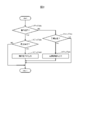
- FIG. (1) of FIG. 9 shows the constant speed start determination (target speed presentation), and (2) of FIG. 9 shows the coasting start determination (coasting start position presentation).
- Reference numeral 91 in FIG. 9 indicates position accuracy deterioration (e.g., when the travel distance has advanced due to the occurrence of idling), and reference numeral 92 in FIG. 9 indicates that the coasting position is shifted and the speed is decreased.
- the example of FIG. 9 shows a case where idling occurs after acceleration after leaving the station, and the on-line position recognized by the train goes forward in the direction of travel than the original on-line position.
- the coasting start position before the downhill is ahead of the schedule because recognition of the position on the track is advancing.
- the speed decrease before the down slope becomes too large, and the traveling speed after coasting decreases.
- the coasting position before the stop brake is also in front of the schedule, and coasting longer than the schedule. This way of traveling reduces the overall traveling speed between stations, leading to a late arrival.
- the present invention has been made in consideration of the above points, and to provide a driving support technology capable of suppressing deterioration of regularity, in particular, late arrival even when the accuracy of train location recognition on the train is deteriorated. To aim.
- a typical driving support system of the present invention is a driving support system that supports a driving operation while traveling between trains, and determines a target speed according to the location of the train.
- a coasting support unit for determining a coasting position according to the train location, and a train location recognition accuracy detection unit for outputting a train location recognition accuracy which is a train location recognition accuracy.
- a support information determination unit configured to determine driving support information, wherein the support information determination unit combines the target speed and the coasting position according to the on-rail position recognition accuracy to create the driving support information. It is a driving support system.
- the present invention while supporting energy saving traveling, it is possible to suppress the deterioration of regularity even when the accuracy in recognizing the on-rail position of the train is deteriorated.
- FIG. 1 is a diagram illustrating an example of a system configuration of a driving support system according to a first embodiment. It is a figure which shows an example of the processing flow of a support information determination part. It is a figure which shows an example of the detection method of a standing line position recognition precision detection part. It is a figure which shows an example of the detection method of a standing line position recognition precision detection part. It is a figure which shows an example of the detection method of a standing line position recognition precision detection part. It is a figure which shows an example of the detection method of a standing line position recognition precision detection part. It is a figure which shows an example of the detection method of a standing line position recognition precision detection part. It is a figure which shows an example of the detection method of a standing line position recognition precision detection part.
- FIG. 7 is a diagram illustrating an example of a system configuration of a driving support system according to a second embodiment.
- FIG. 16 is a diagram showing an example of display content transition of the display in the driving support system according to the second embodiment (when the on-rail position recognition accuracy is good).
- FIG. 16 is a diagram illustrating another example of display content transition of the display in the driving support system according to the second embodiment (when the on-rail position recognition accuracy is deteriorated).
- FIG. 1 is a diagram showing a system configuration of a driving support system of the present embodiment.
- the driving support system 100 determines a command to the control and driving device 103 based on the information acquired from the vehicle information control device 101 and the information acquired from the security device 102, and automatically operates the train.
- the information acquired by the driving support system 100 from the vehicle information control device 101 includes the remaining traveling time 150, the vehicle speed 151, the location information 152, the braking / driving force information 153, the assumed traveling pattern 154, and the slip / slip detection result 155. It is. Also, the information that the driving support system 100 acquires from the security device 102 is a speed limit 171.
- the remaining travel time 150 is a value calculated inside the vehicle information control apparatus 101, and an example of the calculation method is a method of subtracting the current time from the arrival target time of the next station.
- the vehicle information control device 101 generates and manages the vehicle speed 151 from the rotation speed information of a speed generator (not shown) and the like.
- the traveling distance per unit time that is, the speed can be determined by multiplying the wheel rotation number information per unit time generated by the speed generator by the circumferential length of the wheel, and the vehicle speed 151 is generated using this. .
- the vehicle position control information 101 is held by the vehicle information control apparatus 101, and the absolute position detection result by communication with the ground side using a transponder or the like is set as an initial value, and the vehicle speed 151 is set in the section where the communication can not be performed. It is obtained by adding the integrated value, that is, the traveling distance.
- the braking / driving force information 153 is obtained by the vehicle information control device 101 from the braking / driving force device 103 (the route is not shown), and is the actual value or command value of the generated braking / driving force.
- the assumed traveling pattern 154 is a planned speed pattern between the stations, and at least the speed trajectory of the coasting scheduled section between the stations is held in the vehicle information control device 101.
- the vehicle information control device 101 acquires the idling / sliding detection result 155 from the braking / driving force device 103 via information transmission in the vehicle (the route is not shown), and the idling during power running, the sliding during braking Occurrence history of
- the speed limit 171 defines the maximum allowable speed according to the position between stations.
- the driving support system 100 includes a constant speed support unit 110, a flight delay support unit 111, a location recognition accuracy detection unit 112, a support information determination unit 113, and a braking / driving instruction calculation unit 114.
- the constant speed support unit 110 receives the remaining travel time 150, the vehicle speed 151, and the on-rail position information 152, calculates a target speed 160, and outputs the target speed 160 to the support information determination unit 113.
- the method of calculating the target speed 160 will be described later.
- the coasting support unit 111 receives the remaining travel time 150, the vehicle speed 151, and the on-rail position information 152, calculates a coasting position 161, and outputs the coasting position 161 to the support information determination unit 113.
- the calculation method of the crawling position 161 will be described later.
- the on-rail position recognition accuracy detection unit 112 receives the vehicle speed 151, the on-rail position information 152, the braking / driving force information 153, the assumed traveling pattern 154, and the slip / slip detection result 155 as an input. It is calculated and output to the support information determination unit 113.
- the on-rail position accuracy 162 has two values of good and deterioration, and is set to “good” at the timing when the absolute position is corrected by communication with a powered ground terminal such as when the station is stopped.
- the method of calculating the on-rail position accuracy 162 will be described later.
- the support information determination unit 113 calculates driving support information 170 using the target speed 160, the crawling position 161, and the on-rail position accuracy 162 as input, and outputs the driving support information 170 to the braking / driving command calculation unit 114.
- the method of calculating the driving support information 170 will be described later.
- the braking / driving command calculation unit 114 calculates the braking / driving command 180 based on the driving support information 170, the vehicle speed 151, the on-rail position information 152, and the speed limit 171, and outputs it to the braking / driving device 103. Do. The method of calculating the control drive command 180 will be described later.
- the constant speed support unit 110 calculates the speed at which the train should shift to constant speed operation, and outputs the calculated speed as the target speed 160.
- a method of calculating the target speed 160 there is a method of using a constant speed start determination table in which the remaining traveling time is defined for each position and speed between stations.
- the remaining traveling time is defined as the time taken to reach the next station, and the speed is fast or close to the next station Since the time taken to arrive at the next station will be shorter, the remaining travel time will be shorter.
- the remaining travel time 150 is a target value of the time until arrival at the next station, and a larger value means more time.
- a value that achieves more energy saving is determined in advance on a simulation basis while maintaining regularity (of course, the actual value of the train is actually traveled and measured. You may decide).
- the vehicle speed 151 at that time is output as the target speed 160.
- the remaining travel time 150 is smaller than the remaining travel time value corresponding to the current position and speed in the constant speed start determination table, it is necessary to continue the powering so that the target speed 160 is set. Do not set
- the method of calculating the target speed 160 is not limited to the method using the constant speed start determination table, as long as it is a method of calculating the target speed in consideration of regularity and energy saving.
- the coasting support unit 111 calculates a position where the train should shift to coasting operation, and outputs the position as the coasting position 161.
- a method of calculating the coasting position 161 there is a method of using a coasting start determination table in which the remaining traveling time is defined for each position and speed between stations.
- the remaining traveling time is defined as the time taken to arrive at the next station, and the speed is high or When it is near, the time taken to reach the next station will be short, so the remaining driving time will be short.
- a value that achieves more energy saving is determined in advance on a simulation basis while maintaining regularity (of course, the actual value of the train is actually traveled and measured. You may decide).
- the remaining travel time 150 becomes near (for example, within ⁇ 5 seconds) the value for the remaining travel time corresponding to the current position and speed in the coasting start determination table, the existing line at that time
- the position information 152 is output as the crawling position 161.
- the calculation method of the coasting position 161 is not limited to the method using the coasting start determination table, and it may be a calculation method of the coasting position in consideration of regularity and energy saving.
- the on-rail position accuracy 162 outputted by the on-rail position recognition accuracy detection unit 112 is a detection result regarding the consistency between the true position of the train and the on-rail position information 152. As described below, there are various detection methods, and by combining a plurality of detection methods, the on-rail position accuracy 162 can be detected more accurately.
- One example of a method of detecting the on-rail position accuracy 162 is a method based on the continuity of the on-rail position information 152.
- the on-rail location information 152 changes continuously with time.
- the traveling distance calculated by integrating the number of revolutions changes suddenly, that is, the traveling distance changes significantly within a short time.
- FIG. 3 An example is shown in FIG. In FIG. 3, it appears as if the train, which was at position L0 at time T0 and accelerated to time T1 and reached position L1, moved to L1 'after a short time ⁇ T due to a slip. In such a case, it is determined that the on-rail position accuracy 162 after T1 + ⁇ T is degraded.
- the determination method a method of determining whether (L1′ ⁇ L1) ⁇ ⁇ T exceeds the maximum speed of the train or the maximum acceleration that can be generated from the change of the traveling distance can be generated by the driving force of the target train There is a method of determining whether or not the acceleration is exceeded.
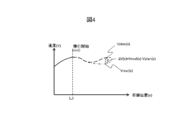
- the detection method of the on-rail position accuracy 162 there is a method based on a difference between a velocity locus during traveling and a velocity locus assumed. This is based on the idea that, when the on-rail position accuracy 162 is deteriorated, the running resistance resulting from the route condition is different from the assumption, so that the trajectory of the speed is different from the assumption even during the same driving operation.
- FIG. 4 A conceptual diagram is shown in FIG. Here, it is judged from the braking / driving force information 153 whether or not the train is coasting.
- a velocity locus obtained by accumulation of the vehicle velocity 151 is a dashed line (Vreal (x)) in FIG.
- the coasting is mentioned as an example here because there is no disturbance effect on the acceleration / deceleration due to the overhead wire voltage fluctuation that exists during power running and braking, and it is easy to compare the velocity locus. However, it is also possible to compare the speed trajectory during powering and braking, and the application of the method is not limited to coasting.
- the detection method of the on-rail position accuracy 162 there is a method based on a comparison result of detection results by a plurality of position detection means.
- a method based on the speed detection result by a millimeter wave radar, a method by feature point recognition of the external world using a sensor, or GPS It is possible to use a plurality of methods together, such as a method using
- the detection results by the plurality of position detection means included in the on-line position information 152 are compared, and when the deviation of the position is large, it can be considered that at least one on-line position accuracy is deteriorated. It can be said that the on-rail position accuracy 162 is deteriorated.
- the deviation of the detection results of the on-rail position by the two types of position detection means exceeds a threshold (for example, 5% of the traveling distance from the station to the current position). It is determined that the on-rail position accuracy 162 is worse.
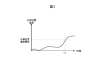
- the detection method of the on-rail position accuracy 162 there is a method based on the occurrence history of idling / sliding. If slippage or slippage occurs, the position detection accuracy based on the integration of the wheel rotation number information of the speed generator deteriorates. Therefore, according to the number of integrations of the slippage / slippage detection result 155 There is a conceivable method of determination. In the example shown in FIG. 6, the fourth slip / sliding occurs at time T3, and in this case the determination criterion is four or more, so it is determined that the on-rail position accuracy 162 is worse at this time. Do. Moreover, in the said method, the variation which makes the judgment value the integration result of the duration of idling / sliding is also possible.
- the detection method of the on-line position accuracy 162 in the on-line position recognition accuracy detection unit 112 is not limited thereto.
- the on-rail position information 152 is corrected by a transponder or the like when arriving at the next station or the like, the on-rail position accuracy 162 is reset to the good side at the corrected timing.
- step 201 the support information determination unit 113 determines whether a value is set in the crawling position 161. When the value is set to the crawling position 161, the process proceeds to step 202, and when it is not set, the process proceeds to step 204.
- step 202 the support information determination unit 113 checks the on-rail position accuracy 162 (determines whether the on-rail position accuracy 162 is good). If the on-line position accuracy is good, the process transitions to step 203. If the on-line position accuracy is degraded, the process exits this flow.
- step 203 the support information determination unit 113 sets the coasting position 161 as the driving support information 170 and sends it to the braking / driving instruction calculation unit 114.
- step 204 the support information determination unit 113 determines whether a value has been set for the target speed 160. When a value is set to the target velocity 160, the process transitions to step 205, and when the value is not set, the process flow exits.
- step 205 the support information determination unit 113 sets the target speed 161 as the driving support information 170 and sends it to the braking / driving instruction calculation unit 114.
- the braking / driving command computation unit 114 computes / outputs the braking / driving command 180 so that the vehicle speed 151 does not exceed the speed limit 171 acquired from the security device 102. Also, although not shown in FIG. 1, the braking / driving command 180 is calculated so as to stop along the brake pattern (defined by position and speed) prepared in advance toward the target stop position of the next station. ⁇ Output. The braking / driving command calculation unit 114 calculates the braking / driving command 180 based on the driving support information 170 in a range in which the vehicle speed 151 does not exceed the speed limit 171 and the brake pattern.
- the braking / driving command calculation unit 114 performs powering while periodically checking the content of the driving support information 170 to accelerate the train.
- the braking / driving command 180 is calculated so that the vehicle speed 151 follows the speed.
- coasting position 161 is set in the driving support information 170, coasting starts from that point.
- the coasting position 161 may be set in the driving support information 170 without setting the target speed 160 during power running and acceleration, in which case coasting is started from the point.
- control / drive command calculation unit 114 calculates the control / drive command 180 so that the vehicle speed 151 does not exceed the speed limit. . After the speed limit disappears, the flow is the same as after leaving the station.
- the braking / driving command calculation unit 114 prevents the vehicle speed 151 from exceeding the speed of the braking pattern.
- the command 180 is calculated.
- the control for causing the vehicle speed 151 to follow the target speed (the target speed 160 and the speed limit 171) in the braking / driving command calculation unit 114 may be exemplified by proportional control, fuzzy control, etc. There is no limitation on the control method in the present embodiment.
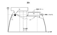
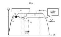
- FIG. (1) of FIG. 10 shows a constant speed start determination (target speed presentation), and (2) of FIG. 10 shows a coasting start determination (coasting start position presentation).
- symbol 11 of FIG. 10 shows position accuracy deterioration (example: when traveling distance advances by slippage occurrence), and the code
- idling occurs during constant speed traveling after leaving the station, and detection accuracy of the on-rail position is deteriorated.
- the cruise speed in the second half of the station has been reduced because it started coasting in the middle of the station.
- the deterioration of the on-rail position detection accuracy is detected by the method based on the deviation of the velocity locus shown in FIG. As a result, the subsequent coasting support is canceled and the coasting before the stop brake is not inserted, and the influence of the late arrival to the next station can be suppressed.
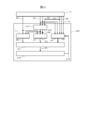
- FIG. 11 is a diagram showing a system configuration of the driving support system of the present embodiment.
- the driving support system 1100 performs driving support based on the information acquired from the vehicle information control device 101.
- the information acquired by the driving support system 1100 from the vehicle information control device 101 includes the remaining traveling time 150, the vehicle speed 151, the location information 152, the braking / driving force information 153, the assumed traveling pattern 154, and the slip / slip detection result 155. It is.
- the remaining traveling time 150, the vehicle speed 151, the on-rail position information 152, the braking / driving force information 153, the assumed traveling pattern 154, and the slippage / slippage detection result 155 are as described in the first embodiment.
- the driving support system 1100 includes a position / speed prediction unit 1115, a constant speed support unit 110, a crawling support unit 111, a position recognition accuracy detection unit 112, a support information determination unit 113, and a display 1114. .
- the position / speed prediction unit 1115 calculates the predicted speed 1163 and the predicted position 1164 by using the vehicle speed 151, the on-line position information 152 and the braking / driving force information 153 as input, and the constant speed support unit 110 It outputs to the crawling support unit 111.
- the method of calculating the predicted velocity 1163 and the predicted position 1164 will be described later.
- the constant speed support unit 110 receives the remaining travel time 150, the predicted speed 1163, and the predicted position 1164 as input, calculates a target speed 160, and outputs the target speed 160 to the support information determination unit 113.
- the method of calculating the target speed 160 will be described later.
- the coasting support unit 111 receives the remaining travel time 150, the predicted speed 1163, and the predicted position 1164 as input, calculates a coasting position 161, and outputs the coasting position 161 to the support information determination unit 113.
- the calculation method of the crawling position 161 will be described later.
- the on-rail position recognition accuracy detection unit 112 receives the vehicle speed 151, the on-rail position information 152, the braking / driving force information 153, the assumed traveling pattern 154, the idling / sliding detection result 155, and the crew input result 1171 as input.
- the position accuracy 162 is calculated and output to the support information determination unit 113. The method of calculating the on-rail position accuracy 162 will be described later.
- the support information determination unit 113 receives the target speed 160, the crawling position 161, and the on-rail position accuracy 162, calculates driving support information 170, and outputs the driving support information 170 to the display 1114.
- the method of calculating the driving support information 170 will be described later.
- the display 1114 receives the driving support information 170 and teaches the driving support content for the driver by screen display and / or sound ringing. A specific example of driving assistance content teaching will be described later.
- the position / speed prediction unit 1115 the constant-speed support unit 110, the coasting support unit 111, the on-rail position recognition accuracy detection unit 112, and the support information determination unit included in the driving support system 1100 of the present embodiment.
- the calculation method of each output data in 113 and the said display 1114 is demonstrated.
- the position / speed prediction unit 1115 predicts the speed and position of the train after a predetermined time. This is because it is necessary to teach the driving operation contents at a timing earlier than the driving operation timing actually required for the crew due to the characteristic of the function of driving support in the manual driving.
- the position / speed prediction unit 1115 assumes that the braking / driving force information 153 continues until a predetermined time after the vehicle speed 151 and the on-rail position information 152 as a reference. Then, the predicted velocity 1163 and the predicted position 1164 are calculated.
- the predetermined time for prediction is determined so that the crew can shift to the operation with a margin after perceiving the content of the support.
- the calculation process of the target speed 160 in the constant speed support unit 110 uses the predicted speed 1163 and the predicted position 1164 in the present embodiment instead of the vehicle speed 151 and the line location information 152 in the first embodiment. Calculated by The specific calculation method is as described in the first embodiment.
- the calculation process of the coasting position 161 in the coasting support unit 111 uses the predicted speed 1163 and the predicted position 1164 of the present embodiment instead of the vehicle speed 151 and the on-rail position information 152 in the first embodiment. It is calculated.
- the specific calculation method is as described in the first embodiment.
- the on-rail position accuracy 162 outputted by the on-rail position recognition accuracy detection unit 112 is a detection result regarding the consistency between the true position of the train and the on-rail position information 152.
- FIG. 3 The detection method described in FIG. 3, FIG. 4, FIG. 5, and FIG. 6 of the first embodiment is also applicable to this embodiment.
- the method of notification from the crew is not limited to this.
- these notifications are received, it is determined that the on-rail position accuracy 162 has deteriorated.
- the same user interface may be used to allow the crew to input that the accuracy of the on-rail position recognition has recovered.
- the above is the example of the detection method of the on-line position accuracy 162 in the on-line position recognition accuracy detection unit 112, but it goes without saying that the detection method of the on-line position accuracy 162 is not limited thereto.
- the calculation method of the driving support information 170 in the support information determination unit 113 is as described in the first embodiment.
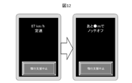
- the display 1114 teaches support content for the crew in accordance with the driving support information 170.
- FIG. 12 shows an example in which the content of the driving operation is displayed on the display 1114 installed in the cab.
- driving operation details such as "87 km / h constant speed", and when the coasting position 161 is set, "notch off at -m” are displayed. Ru.
- teaching by sounding is also possible, and it is conceivable to use both in combination.
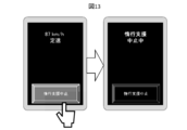
- the display 1114 in FIG. 12 is provided with a button for instructing the suspension support cancellation, and the result of handling this is reflected in the crew input result 1171.
- An example in which the button is handled is shown in FIG. In FIG. 13, on the basis of the input of the crew input result 1171, a transition is made to a state where the coasting support is not provided.
- the on-rail position information 152 is generally corrected by a transponder or the like, and it is desirable to exit from the coasting support cancellation mode at that timing.
- the driving support system 1100 described in the present embodiment it is possible to suppress the deterioration of the on-time performance and the energy saving performance even when the on-rail position detection accuracy is deteriorated.
- the suppression of deterioration of the scheduled operation is as described in the first embodiment, the system side guarantees the suppression of the deterioration of the scheduled operation with respect to the support of the manual operation described in the present embodiment, so that the delay recovery by the crew is recovered. It is possible to suppress excessive powering operations aimed at reducing the energy saving performance.
Landscapes
- Engineering & Computer Science (AREA)
- Power Engineering (AREA)
- Transportation (AREA)
- Mechanical Engineering (AREA)
- Electric Propulsion And Braking For Vehicles (AREA)
- Train Traffic Observation, Control, And Security (AREA)
Applications Claiming Priority (2)
| Application Number | Priority Date | Filing Date | Title |
|---|---|---|---|
| JP2018000050A JP6914203B2 (ja) | 2018-01-04 | 2018-01-04 | 運転支援システム |
| JP2018-000050 | 2018-01-04 |
Publications (1)
| Publication Number | Publication Date |
|---|---|
| WO2019135310A1 true WO2019135310A1 (ja) | 2019-07-11 |
Family
ID=67144446
Family Applications (1)
| Application Number | Title | Priority Date | Filing Date |
|---|---|---|---|
| PCT/JP2018/040006 Ceased WO2019135310A1 (ja) | 2018-01-04 | 2018-10-26 | 運転支援システム |
Country Status (2)
| Country | Link |
|---|---|
| JP (1) | JP6914203B2 (enExample) |
| WO (1) | WO2019135310A1 (enExample) |
Families Citing this family (2)
| Publication number | Priority date | Publication date | Assignee | Title |
|---|---|---|---|---|
| JP7426256B2 (ja) * | 2020-02-27 | 2024-02-01 | 株式会社日立製作所 | 省エネ運転支援システム及びその方法 |
| JP7303142B2 (ja) * | 2020-03-17 | 2023-07-04 | 株式会社日立製作所 | 運転支援装置および運転支援方法 |
Citations (3)
| Publication number | Priority date | Publication date | Assignee | Title |
|---|---|---|---|---|
| JP2015043673A (ja) * | 2013-08-26 | 2015-03-05 | 株式会社東芝 | 列車制御装置 |
| WO2016121606A1 (ja) * | 2015-01-28 | 2016-08-04 | 三菱電機株式会社 | 列車位置検知装置 |
| JP2017085688A (ja) * | 2015-10-23 | 2017-05-18 | 株式会社日立製作所 | 自動列車運転装置および列車運転支援装置 |
-
2018
- 2018-01-04 JP JP2018000050A patent/JP6914203B2/ja active Active
- 2018-10-26 WO PCT/JP2018/040006 patent/WO2019135310A1/ja not_active Ceased
Patent Citations (3)
| Publication number | Priority date | Publication date | Assignee | Title |
|---|---|---|---|---|
| JP2015043673A (ja) * | 2013-08-26 | 2015-03-05 | 株式会社東芝 | 列車制御装置 |
| WO2016121606A1 (ja) * | 2015-01-28 | 2016-08-04 | 三菱電機株式会社 | 列車位置検知装置 |
| JP2017085688A (ja) * | 2015-10-23 | 2017-05-18 | 株式会社日立製作所 | 自動列車運転装置および列車運転支援装置 |
Also Published As
| Publication number | Publication date |
|---|---|
| JP6914203B2 (ja) | 2021-08-04 |
| JP2019122131A (ja) | 2019-07-22 |
Similar Documents
| Publication | Publication Date | Title |
|---|---|---|
| JP5199315B2 (ja) | 列車自動運転における速度制御装置 | |
| CN102470868B (zh) | 车辆控制装置、车辆控制方法以及车辆控制系统 | |
| KR102269924B1 (ko) | 열차 제어 장치, 방법 및 기록 매체 | |
| JP3234925B2 (ja) | 列車制御装置 | |
| KR101866610B1 (ko) | 철도 차량에서의 제한속도 초과 경고 장치 | |
| US10150491B2 (en) | Device and method for controlling train | |
| CN105501252A (zh) | 一种列车运行控制设备和方法 | |
| WO2019135310A1 (ja) | 運転支援システム | |
| US10336324B2 (en) | Calculation of the time to collision for a vehicle | |
| JP2001154733A (ja) | 車両の自動走行制御方法および自動走行制御装置 | |
| JP2017085688A (ja) | 自動列車運転装置および列車運転支援装置 | |
| JP4005541B2 (ja) | 列車走行制御システムおよび列車走行制御方法 | |
| JP2019089449A (ja) | 列車走行制御装置、方法及びプログラム | |
| JP6451560B2 (ja) | 車両認識装置 | |
| EP2979952B1 (en) | Method for reducing the delay of a rail vehicle to reach a destination | |
| EP3192717A1 (en) | Operation control system | |
| JP2006006030A (ja) | 運転パターン作成装置、車両速度制御装置および車両運転支援装置。 | |
| CN111361606A (zh) | 一种机车的准时到站控制方法、装置、介质及设备 | |
| JP5364682B2 (ja) | 列車の定速走行制御方法及び装置 | |
| JP5512193B2 (ja) | 列車制御方法、列車制御装置、および車両 | |
| JP2006074876A (ja) | 車両の定位置停止自動制御装置 | |
| US11400905B2 (en) | Vehicle control device, vehicle control method and program | |
| JPH11234813A (ja) | 列車の自動運転制御装置 | |
| JP6802091B2 (ja) | 列車制御システム、列車制御方法および列車の車上装置 | |
| JP2006290149A (ja) | 車両用走行制御装置 |
Legal Events
| Date | Code | Title | Description |
|---|---|---|---|
| 121 | Ep: the epo has been informed by wipo that ep was designated in this application |
Ref document number: 18898585 Country of ref document: EP Kind code of ref document: A1 |
|
| NENP | Non-entry into the national phase |
Ref country code: DE |
|
| 122 | Ep: pct application non-entry in european phase |
Ref document number: 18898585 Country of ref document: EP Kind code of ref document: A1 |