WO2019135310A1 - Operation assistance system - Google Patents
Operation assistance system Download PDFInfo
- Publication number
- WO2019135310A1 WO2019135310A1 PCT/JP2018/040006 JP2018040006W WO2019135310A1 WO 2019135310 A1 WO2019135310 A1 WO 2019135310A1 JP 2018040006 W JP2018040006 W JP 2018040006W WO 2019135310 A1 WO2019135310 A1 WO 2019135310A1
- Authority
- WO
- WIPO (PCT)
- Prior art keywords
- driving support
- rail position
- driving
- support system
- accuracy
- Prior art date
Links
Images


Classifications
-
- B—PERFORMING OPERATIONS; TRANSPORTING
- B60—VEHICLES IN GENERAL
- B60L—PROPULSION OF ELECTRICALLY-PROPELLED VEHICLES; SUPPLYING ELECTRIC POWER FOR AUXILIARY EQUIPMENT OF ELECTRICALLY-PROPELLED VEHICLES; ELECTRODYNAMIC BRAKE SYSTEMS FOR VEHICLES IN GENERAL; MAGNETIC SUSPENSION OR LEVITATION FOR VEHICLES; MONITORING OPERATING VARIABLES OF ELECTRICALLY-PROPELLED VEHICLES; ELECTRIC SAFETY DEVICES FOR ELECTRICALLY-PROPELLED VEHICLES
- B60L15/00—Methods, circuits, or devices for controlling the traction-motor speed of electrically-propelled vehicles
- B60L15/40—Adaptation of control equipment on vehicle for remote actuation from a stationary place
Definitions
- the present invention relates to a driving support technique for a mobile unit performing rail transportation including railways.
- ATO Automatic Train Operation
- ATO devices have been introduced on many routes with the aim of reducing the burden on crews and reducing labor costs against the background of crowded train operation schedules and maintenance and improvement of home doors. There is. In recent years, in addition to regular operation and labor saving, which is the original purpose, reduction of power consumption is also required of ATO devices. On the other hand, for a route where the ATO device has not been introduced, introduction of a driving support device that supports the driver in driving operation has also been promoted so that driving can be performed with a traveling pattern with low power consumption.
- the ATO device and the driving support device for the purpose of energy saving execute the traveling control and the driving operation support based on the traveling pattern with a small amount of power consumption derived in advance by simulation.
- traveling can not be performed according to the traveling pattern derived by simulation due to conditions (for example, overhead wire voltage, boarding rate) different from the preconditions of the simulation.
- Patent Document 1 discloses a technique for correcting a traveling pattern according to an actual traveling record. Specifically, when traveling between stations in combination with constant speed traveling and coasting, the constant speed start determination unit that determines the timing to start constant speed traveling and the coasting start determination unit that determines the timing to start coasting A driving support system is disclosed that outputs a powering command / a constant speed command / a coasting command to a driving support device based on the remaining driving time.
- FIG. (1) of FIG. 8 shows the constant speed start determination (target speed presentation), and (2) of FIG. 8 shows the coasting start determination (coasting start position presentation).
- target speed presentation shows the constant speed start determination
- coasting start position presentation shows the coasting start determination
- the horizontal axis shows the position of the train
- the vertical axis shows the speed of the train.
- the first is to support cruising at an appropriate target speed, which suppresses excessive acceleration in consideration of on-time performance, and contributes to the reduction of power consumption ((1) in FIG. 8).
- the second is to support coasting at an appropriate position, which has a great influence on on-time performance while reducing power consumption ((2) in FIG. 8).
- the former target speed support is often used relatively in the first half of inter-station travel (for example, at the point where acceleration after train departure ends), and the latter coasting position support is frequently used in the second half of inter-station travel ( There is a tendency of coasting utilization on downhill during cruise and coasting insertion before stop brake).
- the recognition of the train location is calculated by integrating the vehicle speed based on the wheel rotation speed detected by the speed generator. Therefore, due to events such as wheel diameter error, integral error, or slippage / slippage, an error tends to be inherent in the recognition of the on-rail position especially in the latter half of traveling between stations. If the above-mentioned crawling support is continued when the accuracy of the recognition of the existing line position is deteriorated, the crawling can not be performed at an appropriate position. As a result, deviation from the planned travel pattern may lead to deterioration of on-time performance.
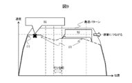
- FIG. (1) of FIG. 9 shows the constant speed start determination (target speed presentation), and (2) of FIG. 9 shows the coasting start determination (coasting start position presentation).
- Reference numeral 91 in FIG. 9 indicates position accuracy deterioration (e.g., when the travel distance has advanced due to the occurrence of idling), and reference numeral 92 in FIG. 9 indicates that the coasting position is shifted and the speed is decreased.
- the example of FIG. 9 shows a case where idling occurs after acceleration after leaving the station, and the on-line position recognized by the train goes forward in the direction of travel than the original on-line position.
- the coasting start position before the downhill is ahead of the schedule because recognition of the position on the track is advancing.
- the speed decrease before the down slope becomes too large, and the traveling speed after coasting decreases.
- the coasting position before the stop brake is also in front of the schedule, and coasting longer than the schedule. This way of traveling reduces the overall traveling speed between stations, leading to a late arrival.
- the present invention has been made in consideration of the above points, and to provide a driving support technology capable of suppressing deterioration of regularity, in particular, late arrival even when the accuracy of train location recognition on the train is deteriorated. To aim.
- a typical driving support system of the present invention is a driving support system that supports a driving operation while traveling between trains, and determines a target speed according to the location of the train.
- a coasting support unit for determining a coasting position according to the train location, and a train location recognition accuracy detection unit for outputting a train location recognition accuracy which is a train location recognition accuracy.
- a support information determination unit configured to determine driving support information, wherein the support information determination unit combines the target speed and the coasting position according to the on-rail position recognition accuracy to create the driving support information. It is a driving support system.
- the present invention while supporting energy saving traveling, it is possible to suppress the deterioration of regularity even when the accuracy in recognizing the on-rail position of the train is deteriorated.
- FIG. 1 is a diagram illustrating an example of a system configuration of a driving support system according to a first embodiment. It is a figure which shows an example of the processing flow of a support information determination part. It is a figure which shows an example of the detection method of a standing line position recognition precision detection part. It is a figure which shows an example of the detection method of a standing line position recognition precision detection part. It is a figure which shows an example of the detection method of a standing line position recognition precision detection part. It is a figure which shows an example of the detection method of a standing line position recognition precision detection part. It is a figure which shows an example of the detection method of a standing line position recognition precision detection part. It is a figure which shows an example of the detection method of a standing line position recognition precision detection part.
- FIG. 7 is a diagram illustrating an example of a system configuration of a driving support system according to a second embodiment.
- FIG. 16 is a diagram showing an example of display content transition of the display in the driving support system according to the second embodiment (when the on-rail position recognition accuracy is good).
- FIG. 16 is a diagram illustrating another example of display content transition of the display in the driving support system according to the second embodiment (when the on-rail position recognition accuracy is deteriorated).
- FIG. 1 is a diagram showing a system configuration of a driving support system of the present embodiment.
- the driving support system 100 determines a command to the control and driving device 103 based on the information acquired from the vehicle information control device 101 and the information acquired from the security device 102, and automatically operates the train.
- the information acquired by the driving support system 100 from the vehicle information control device 101 includes the remaining traveling time 150, the vehicle speed 151, the location information 152, the braking / driving force information 153, the assumed traveling pattern 154, and the slip / slip detection result 155. It is. Also, the information that the driving support system 100 acquires from the security device 102 is a speed limit 171.
- the remaining travel time 150 is a value calculated inside the vehicle information control apparatus 101, and an example of the calculation method is a method of subtracting the current time from the arrival target time of the next station.
- the vehicle information control device 101 generates and manages the vehicle speed 151 from the rotation speed information of a speed generator (not shown) and the like.
- the traveling distance per unit time that is, the speed can be determined by multiplying the wheel rotation number information per unit time generated by the speed generator by the circumferential length of the wheel, and the vehicle speed 151 is generated using this. .
- the vehicle position control information 101 is held by the vehicle information control apparatus 101, and the absolute position detection result by communication with the ground side using a transponder or the like is set as an initial value, and the vehicle speed 151 is set in the section where the communication can not be performed. It is obtained by adding the integrated value, that is, the traveling distance.
- the braking / driving force information 153 is obtained by the vehicle information control device 101 from the braking / driving force device 103 (the route is not shown), and is the actual value or command value of the generated braking / driving force.
- the assumed traveling pattern 154 is a planned speed pattern between the stations, and at least the speed trajectory of the coasting scheduled section between the stations is held in the vehicle information control device 101.
- the vehicle information control device 101 acquires the idling / sliding detection result 155 from the braking / driving force device 103 via information transmission in the vehicle (the route is not shown), and the idling during power running, the sliding during braking Occurrence history of
- the speed limit 171 defines the maximum allowable speed according to the position between stations.
- the driving support system 100 includes a constant speed support unit 110, a flight delay support unit 111, a location recognition accuracy detection unit 112, a support information determination unit 113, and a braking / driving instruction calculation unit 114.
- the constant speed support unit 110 receives the remaining travel time 150, the vehicle speed 151, and the on-rail position information 152, calculates a target speed 160, and outputs the target speed 160 to the support information determination unit 113.
- the method of calculating the target speed 160 will be described later.
- the coasting support unit 111 receives the remaining travel time 150, the vehicle speed 151, and the on-rail position information 152, calculates a coasting position 161, and outputs the coasting position 161 to the support information determination unit 113.
- the calculation method of the crawling position 161 will be described later.
- the on-rail position recognition accuracy detection unit 112 receives the vehicle speed 151, the on-rail position information 152, the braking / driving force information 153, the assumed traveling pattern 154, and the slip / slip detection result 155 as an input. It is calculated and output to the support information determination unit 113.
- the on-rail position accuracy 162 has two values of good and deterioration, and is set to “good” at the timing when the absolute position is corrected by communication with a powered ground terminal such as when the station is stopped.
- the method of calculating the on-rail position accuracy 162 will be described later.
- the support information determination unit 113 calculates driving support information 170 using the target speed 160, the crawling position 161, and the on-rail position accuracy 162 as input, and outputs the driving support information 170 to the braking / driving command calculation unit 114.
- the method of calculating the driving support information 170 will be described later.
- the braking / driving command calculation unit 114 calculates the braking / driving command 180 based on the driving support information 170, the vehicle speed 151, the on-rail position information 152, and the speed limit 171, and outputs it to the braking / driving device 103. Do. The method of calculating the control drive command 180 will be described later.
- the constant speed support unit 110 calculates the speed at which the train should shift to constant speed operation, and outputs the calculated speed as the target speed 160.
- a method of calculating the target speed 160 there is a method of using a constant speed start determination table in which the remaining traveling time is defined for each position and speed between stations.
- the remaining traveling time is defined as the time taken to reach the next station, and the speed is fast or close to the next station Since the time taken to arrive at the next station will be shorter, the remaining travel time will be shorter.
- the remaining travel time 150 is a target value of the time until arrival at the next station, and a larger value means more time.
- a value that achieves more energy saving is determined in advance on a simulation basis while maintaining regularity (of course, the actual value of the train is actually traveled and measured. You may decide).
- the vehicle speed 151 at that time is output as the target speed 160.
- the remaining travel time 150 is smaller than the remaining travel time value corresponding to the current position and speed in the constant speed start determination table, it is necessary to continue the powering so that the target speed 160 is set. Do not set
- the method of calculating the target speed 160 is not limited to the method using the constant speed start determination table, as long as it is a method of calculating the target speed in consideration of regularity and energy saving.
- the coasting support unit 111 calculates a position where the train should shift to coasting operation, and outputs the position as the coasting position 161.
- a method of calculating the coasting position 161 there is a method of using a coasting start determination table in which the remaining traveling time is defined for each position and speed between stations.
- the remaining traveling time is defined as the time taken to arrive at the next station, and the speed is high or When it is near, the time taken to reach the next station will be short, so the remaining driving time will be short.
- a value that achieves more energy saving is determined in advance on a simulation basis while maintaining regularity (of course, the actual value of the train is actually traveled and measured. You may decide).
- the remaining travel time 150 becomes near (for example, within ⁇ 5 seconds) the value for the remaining travel time corresponding to the current position and speed in the coasting start determination table, the existing line at that time
- the position information 152 is output as the crawling position 161.
- the calculation method of the coasting position 161 is not limited to the method using the coasting start determination table, and it may be a calculation method of the coasting position in consideration of regularity and energy saving.
- the on-rail position accuracy 162 outputted by the on-rail position recognition accuracy detection unit 112 is a detection result regarding the consistency between the true position of the train and the on-rail position information 152. As described below, there are various detection methods, and by combining a plurality of detection methods, the on-rail position accuracy 162 can be detected more accurately.
- One example of a method of detecting the on-rail position accuracy 162 is a method based on the continuity of the on-rail position information 152.
- the on-rail location information 152 changes continuously with time.
- the traveling distance calculated by integrating the number of revolutions changes suddenly, that is, the traveling distance changes significantly within a short time.
- FIG. 3 An example is shown in FIG. In FIG. 3, it appears as if the train, which was at position L0 at time T0 and accelerated to time T1 and reached position L1, moved to L1 'after a short time ⁇ T due to a slip. In such a case, it is determined that the on-rail position accuracy 162 after T1 + ⁇ T is degraded.
- the determination method a method of determining whether (L1′ ⁇ L1) ⁇ ⁇ T exceeds the maximum speed of the train or the maximum acceleration that can be generated from the change of the traveling distance can be generated by the driving force of the target train There is a method of determining whether or not the acceleration is exceeded.
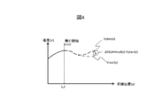
- the detection method of the on-rail position accuracy 162 there is a method based on a difference between a velocity locus during traveling and a velocity locus assumed. This is based on the idea that, when the on-rail position accuracy 162 is deteriorated, the running resistance resulting from the route condition is different from the assumption, so that the trajectory of the speed is different from the assumption even during the same driving operation.
- FIG. 4 A conceptual diagram is shown in FIG. Here, it is judged from the braking / driving force information 153 whether or not the train is coasting.
- a velocity locus obtained by accumulation of the vehicle velocity 151 is a dashed line (Vreal (x)) in FIG.
- the coasting is mentioned as an example here because there is no disturbance effect on the acceleration / deceleration due to the overhead wire voltage fluctuation that exists during power running and braking, and it is easy to compare the velocity locus. However, it is also possible to compare the speed trajectory during powering and braking, and the application of the method is not limited to coasting.
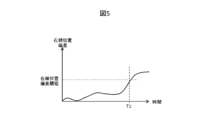
- the detection method of the on-rail position accuracy 162 there is a method based on a comparison result of detection results by a plurality of position detection means.
- a method based on the speed detection result by a millimeter wave radar, a method by feature point recognition of the external world using a sensor, or GPS It is possible to use a plurality of methods together, such as a method using
- the detection results by the plurality of position detection means included in the on-line position information 152 are compared, and when the deviation of the position is large, it can be considered that at least one on-line position accuracy is deteriorated. It can be said that the on-rail position accuracy 162 is deteriorated.
- the deviation of the detection results of the on-rail position by the two types of position detection means exceeds a threshold (for example, 5% of the traveling distance from the station to the current position). It is determined that the on-rail position accuracy 162 is worse.
- the detection method of the on-rail position accuracy 162 there is a method based on the occurrence history of idling / sliding. If slippage or slippage occurs, the position detection accuracy based on the integration of the wheel rotation number information of the speed generator deteriorates. Therefore, according to the number of integrations of the slippage / slippage detection result 155 There is a conceivable method of determination. In the example shown in FIG. 6, the fourth slip / sliding occurs at time T3, and in this case the determination criterion is four or more, so it is determined that the on-rail position accuracy 162 is worse at this time. Do. Moreover, in the said method, the variation which makes the judgment value the integration result of the duration of idling / sliding is also possible.
- the detection method of the on-line position accuracy 162 in the on-line position recognition accuracy detection unit 112 is not limited thereto.
- the on-rail position information 152 is corrected by a transponder or the like when arriving at the next station or the like, the on-rail position accuracy 162 is reset to the good side at the corrected timing.
- step 201 the support information determination unit 113 determines whether a value is set in the crawling position 161. When the value is set to the crawling position 161, the process proceeds to step 202, and when it is not set, the process proceeds to step 204.
- step 202 the support information determination unit 113 checks the on-rail position accuracy 162 (determines whether the on-rail position accuracy 162 is good). If the on-line position accuracy is good, the process transitions to step 203. If the on-line position accuracy is degraded, the process exits this flow.
- step 203 the support information determination unit 113 sets the coasting position 161 as the driving support information 170 and sends it to the braking / driving instruction calculation unit 114.
- step 204 the support information determination unit 113 determines whether a value has been set for the target speed 160. When a value is set to the target velocity 160, the process transitions to step 205, and when the value is not set, the process flow exits.
- step 205 the support information determination unit 113 sets the target speed 161 as the driving support information 170 and sends it to the braking / driving instruction calculation unit 114.
- the braking / driving command computation unit 114 computes / outputs the braking / driving command 180 so that the vehicle speed 151 does not exceed the speed limit 171 acquired from the security device 102. Also, although not shown in FIG. 1, the braking / driving command 180 is calculated so as to stop along the brake pattern (defined by position and speed) prepared in advance toward the target stop position of the next station. ⁇ Output. The braking / driving command calculation unit 114 calculates the braking / driving command 180 based on the driving support information 170 in a range in which the vehicle speed 151 does not exceed the speed limit 171 and the brake pattern.
- the braking / driving command calculation unit 114 performs powering while periodically checking the content of the driving support information 170 to accelerate the train.
- the braking / driving command 180 is calculated so that the vehicle speed 151 follows the speed.
- coasting position 161 is set in the driving support information 170, coasting starts from that point.
- the coasting position 161 may be set in the driving support information 170 without setting the target speed 160 during power running and acceleration, in which case coasting is started from the point.
- control / drive command calculation unit 114 calculates the control / drive command 180 so that the vehicle speed 151 does not exceed the speed limit. . After the speed limit disappears, the flow is the same as after leaving the station.
- the braking / driving command calculation unit 114 prevents the vehicle speed 151 from exceeding the speed of the braking pattern.
- the command 180 is calculated.
- the control for causing the vehicle speed 151 to follow the target speed (the target speed 160 and the speed limit 171) in the braking / driving command calculation unit 114 may be exemplified by proportional control, fuzzy control, etc. There is no limitation on the control method in the present embodiment.
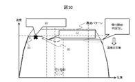
- FIG. (1) of FIG. 10 shows a constant speed start determination (target speed presentation), and (2) of FIG. 10 shows a coasting start determination (coasting start position presentation).
- symbol 11 of FIG. 10 shows position accuracy deterioration (example: when traveling distance advances by slippage occurrence), and the code
- idling occurs during constant speed traveling after leaving the station, and detection accuracy of the on-rail position is deteriorated.
- the cruise speed in the second half of the station has been reduced because it started coasting in the middle of the station.
- the deterioration of the on-rail position detection accuracy is detected by the method based on the deviation of the velocity locus shown in FIG. As a result, the subsequent coasting support is canceled and the coasting before the stop brake is not inserted, and the influence of the late arrival to the next station can be suppressed.
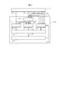
- FIG. 11 is a diagram showing a system configuration of the driving support system of the present embodiment.
- the driving support system 1100 performs driving support based on the information acquired from the vehicle information control device 101.
- the information acquired by the driving support system 1100 from the vehicle information control device 101 includes the remaining traveling time 150, the vehicle speed 151, the location information 152, the braking / driving force information 153, the assumed traveling pattern 154, and the slip / slip detection result 155. It is.
- the remaining traveling time 150, the vehicle speed 151, the on-rail position information 152, the braking / driving force information 153, the assumed traveling pattern 154, and the slippage / slippage detection result 155 are as described in the first embodiment.
- the driving support system 1100 includes a position / speed prediction unit 1115, a constant speed support unit 110, a crawling support unit 111, a position recognition accuracy detection unit 112, a support information determination unit 113, and a display 1114. .
- the position / speed prediction unit 1115 calculates the predicted speed 1163 and the predicted position 1164 by using the vehicle speed 151, the on-line position information 152 and the braking / driving force information 153 as input, and the constant speed support unit 110 It outputs to the crawling support unit 111.
- the method of calculating the predicted velocity 1163 and the predicted position 1164 will be described later.
- the constant speed support unit 110 receives the remaining travel time 150, the predicted speed 1163, and the predicted position 1164 as input, calculates a target speed 160, and outputs the target speed 160 to the support information determination unit 113.
- the method of calculating the target speed 160 will be described later.
- the coasting support unit 111 receives the remaining travel time 150, the predicted speed 1163, and the predicted position 1164 as input, calculates a coasting position 161, and outputs the coasting position 161 to the support information determination unit 113.
- the calculation method of the crawling position 161 will be described later.
- the on-rail position recognition accuracy detection unit 112 receives the vehicle speed 151, the on-rail position information 152, the braking / driving force information 153, the assumed traveling pattern 154, the idling / sliding detection result 155, and the crew input result 1171 as input.
- the position accuracy 162 is calculated and output to the support information determination unit 113. The method of calculating the on-rail position accuracy 162 will be described later.
- the support information determination unit 113 receives the target speed 160, the crawling position 161, and the on-rail position accuracy 162, calculates driving support information 170, and outputs the driving support information 170 to the display 1114.
- the method of calculating the driving support information 170 will be described later.
- the display 1114 receives the driving support information 170 and teaches the driving support content for the driver by screen display and / or sound ringing. A specific example of driving assistance content teaching will be described later.
- the position / speed prediction unit 1115 the constant-speed support unit 110, the coasting support unit 111, the on-rail position recognition accuracy detection unit 112, and the support information determination unit included in the driving support system 1100 of the present embodiment.
- the calculation method of each output data in 113 and the said display 1114 is demonstrated.
- the position / speed prediction unit 1115 predicts the speed and position of the train after a predetermined time. This is because it is necessary to teach the driving operation contents at a timing earlier than the driving operation timing actually required for the crew due to the characteristic of the function of driving support in the manual driving.
- the position / speed prediction unit 1115 assumes that the braking / driving force information 153 continues until a predetermined time after the vehicle speed 151 and the on-rail position information 152 as a reference. Then, the predicted velocity 1163 and the predicted position 1164 are calculated.
- the predetermined time for prediction is determined so that the crew can shift to the operation with a margin after perceiving the content of the support.
- the calculation process of the target speed 160 in the constant speed support unit 110 uses the predicted speed 1163 and the predicted position 1164 in the present embodiment instead of the vehicle speed 151 and the line location information 152 in the first embodiment. Calculated by The specific calculation method is as described in the first embodiment.
- the calculation process of the coasting position 161 in the coasting support unit 111 uses the predicted speed 1163 and the predicted position 1164 of the present embodiment instead of the vehicle speed 151 and the on-rail position information 152 in the first embodiment. It is calculated.
- the specific calculation method is as described in the first embodiment.
- the on-rail position accuracy 162 outputted by the on-rail position recognition accuracy detection unit 112 is a detection result regarding the consistency between the true position of the train and the on-rail position information 152.
- FIG. 3 The detection method described in FIG. 3, FIG. 4, FIG. 5, and FIG. 6 of the first embodiment is also applicable to this embodiment.
- the method of notification from the crew is not limited to this.
- these notifications are received, it is determined that the on-rail position accuracy 162 has deteriorated.
- the same user interface may be used to allow the crew to input that the accuracy of the on-rail position recognition has recovered.
- the above is the example of the detection method of the on-line position accuracy 162 in the on-line position recognition accuracy detection unit 112, but it goes without saying that the detection method of the on-line position accuracy 162 is not limited thereto.
- the calculation method of the driving support information 170 in the support information determination unit 113 is as described in the first embodiment.
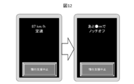
- the display 1114 teaches support content for the crew in accordance with the driving support information 170.
- FIG. 12 shows an example in which the content of the driving operation is displayed on the display 1114 installed in the cab.
- driving operation details such as "87 km / h constant speed", and when the coasting position 161 is set, "notch off at -m” are displayed. Ru.
- teaching by sounding is also possible, and it is conceivable to use both in combination.
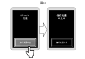
- the display 1114 in FIG. 12 is provided with a button for instructing the suspension support cancellation, and the result of handling this is reflected in the crew input result 1171.
- An example in which the button is handled is shown in FIG. In FIG. 13, on the basis of the input of the crew input result 1171, a transition is made to a state where the coasting support is not provided.
- the on-rail position information 152 is generally corrected by a transponder or the like, and it is desirable to exit from the coasting support cancellation mode at that timing.
- the driving support system 1100 described in the present embodiment it is possible to suppress the deterioration of the on-time performance and the energy saving performance even when the on-rail position detection accuracy is deteriorated.
- the suppression of deterioration of the scheduled operation is as described in the first embodiment, the system side guarantees the suppression of the deterioration of the scheduled operation with respect to the support of the manual operation described in the present embodiment, so that the delay recovery by the crew is recovered. It is possible to suppress excessive powering operations aimed at reducing the energy saving performance.
Landscapes
- Engineering & Computer Science (AREA)
- Power Engineering (AREA)
- Transportation (AREA)
- Mechanical Engineering (AREA)
- Electric Propulsion And Braking For Vehicles (AREA)
- Train Traffic Observation, Control, And Security (AREA)
Abstract
The purpose of the present invention is to provide an operation assistance technique capable of suppressing the deterioration of punctuality even when the accuracy of a train on-rail position has deteriorated. This operation assistance system assists operation maneuvers while a train runs between stations, and is provided with a constant-speed assistance unit for determining a target speed in accordance with the on-rail position of the train, a coasting assistance unit for determining a coasting position in accordance with the on-rail position of the train, an on-rail position recognition accuracy detection unit for outputting on-rail position accuracy that is the accuracy of the on-rail position of the train, and an assistance information determination unit for determining operation assistance information. The operation assistance system is characterized in that the assistance information determination unit creates the operation assistance information by combining the target speed and the coasting position in accordance with the on-rail position accuracy.
Description
本発明は、鉄道をはじめとする軌道輸送を行う移動体の運転支援技術に関する。
TECHNICAL FIELD The present invention relates to a driving support technique for a mobile unit performing rail transportation including railways.
列車運行ダイヤの過密化やホームドアの整備充実化等を背景に、乗務員の負担低減や人件費の削減を目的として、自動列車運転(ATO:Automatic Train Operation)装置が多くの路線で導入されている。近年では、本来の目的である定時運行や省力化に加えて、消費電力量の削減もATO装置に要求されるようになってきている。一方、ATO装置が導入されていない路線向けには、消費電力量が少ない走行パターンで走行できるように、運転士に運転操作の支援を行う運転支援装置の導入も進められている。
Automatic train operation (ATO: Automatic Train Operation) devices have been introduced on many routes with the aim of reducing the burden on crews and reducing labor costs against the background of crowded train operation schedules and maintenance and improvement of home doors. There is. In recent years, in addition to regular operation and labor saving, which is the original purpose, reduction of power consumption is also required of ATO devices. On the other hand, for a route where the ATO device has not been introduced, introduction of a driving support device that supports the driver in driving operation has also been promoted so that driving can be performed with a traveling pattern with low power consumption.
省エネを目的としたATO装置や運転支援装置は、予めシミュレーションで導出された消費電力量が少ない走行パターンに基づいて走行制御や運転操作支援を実施する。ところが実際の走行ではシミュレーションの前提条件とは異なる条件(例えば、架線電圧、乗車率)により、シミュレーションにより導出された走行パターン通りに走行できないことが発生する。
The ATO device and the driving support device for the purpose of energy saving execute the traveling control and the driving operation support based on the traveling pattern with a small amount of power consumption derived in advance by simulation. However, in actual traveling, it may occur that traveling can not be performed according to the traveling pattern derived by simulation due to conditions (for example, overhead wire voltage, boarding rate) different from the preconditions of the simulation.
公知技術として、特許文献1がある。特許文献1には、走行パターンを実際の走行実績に応じて補正する技術が開示されている。具体的には、駅間を定速走行と惰行を組み合わせて走行する場合において、定速走行を開始するタイミングを決定する定速開始判定部と惰行を開始するタイミングを決定する惰行開始判定部を備え、残走行時分に基づいて、力行指示/定速指示/惰行指示を運転支援装置に出力する運転支援システムが開示されている。
There is patent document 1 as a publicly known art. Patent Document 1 discloses a technique for correcting a traveling pattern according to an actual traveling record. Specifically, when traveling between stations in combination with constant speed traveling and coasting, the constant speed start determination unit that determines the timing to start constant speed traveling and the coasting start determination unit that determines the timing to start coasting A driving support system is disclosed that outputs a powering command / a constant speed command / a coasting command to a driving support device based on the remaining driving time.
特許文献1に代表されるように、省エネ運転の支援は大きく2種類に分けられる。支援ポイントの例を図8に示す。図8の(1)は、定速開始判定(目標速度提示)を示し、図8の(2)は、惰行開始判定(惰行開始位置提示)を示す。図8において、横軸は列車の位置を示し、縦軸は列車の速度を示す。一つ目は、適切な目標速度での巡航を支援するもので、定時性を考慮したうえで過剰な加速を抑制し、力行電力の低減に寄与する(図8の(1))。二つ目は、適切な位置での惰行を支援するもので、力行電力を低減しつつ、定時性にも大きな影響を与える(図8の(2))。前者の目標速度の支援は駅間走行の比較的前半に多く活用される(駅発車後の加速を終えるポイントなど)一方で、後者の惰行位置支援は駅間走行の後半に多く活用される(巡航中の下り坂での惰行活用や、停止ブレーキ前の惰行挿入)傾向にある。
As typified by Patent Document 1, the support of the energy saving operation can be roughly divided into two types. An example of a support point is shown in FIG. (1) of FIG. 8 shows the constant speed start determination (target speed presentation), and (2) of FIG. 8 shows the coasting start determination (coasting start position presentation). In FIG. 8, the horizontal axis shows the position of the train, and the vertical axis shows the speed of the train. The first is to support cruising at an appropriate target speed, which suppresses excessive acceleration in consideration of on-time performance, and contributes to the reduction of power consumption ((1) in FIG. 8). The second is to support coasting at an appropriate position, which has a great influence on on-time performance while reducing power consumption ((2) in FIG. 8). The former target speed support is often used relatively in the first half of inter-station travel (for example, at the point where acceleration after train departure ends), and the latter coasting position support is frequently used in the second half of inter-station travel ( There is a tendency of coasting utilization on downhill during cruise and coasting insertion before stop brake).
ここで、列車の在線位置の認識には誤差が含まれやすいという課題がある。一般的に列車の在線位置の認識は、速度発電機で検出された車輪回転数に基づく車両速度の積分で算出される。したがって、車輪径誤差や積分誤差、あるいは空転・滑走といった事象により、特に駅間走行の後半では在線位置の認識に誤差が内在し易い。在線位置の認識の精度が悪化した場合に前記の惰行支援を継続すると、適切な位置で惰行ができなくなる。その結果、予定した走行パターンから逸脱して定時性の悪化につながりかねない。
Here, there is a problem that an error is likely to be included in the recognition of the train location. In general, the recognition of the train location is calculated by integrating the vehicle speed based on the wheel rotation speed detected by the speed generator. Therefore, due to events such as wheel diameter error, integral error, or slippage / slippage, an error tends to be inherent in the recognition of the on-rail position especially in the latter half of traveling between stations. If the above-mentioned crawling support is continued when the accuracy of the recognition of the existing line position is deteriorated, the crawling can not be performed at an appropriate position. As a result, deviation from the planned travel pattern may lead to deterioration of on-time performance.
在線位置認識の精度悪化による悪影響の例を図9に示す。図9の(1)は、定速開始判定(目標速度提示)を示し、図9の(2)は、惰行開始判定(惰行開始位置提示)を示す。図9の符号91は、位置精度悪化(例:空転発生で走行距離が進んだ場合)を示し、図9の符号92は、惰行位置がずれて速度低下、を示す。図9の例では、駅発車後の加速後に空転が発生して、列車が認識している在線位置が本来の在線位置よりも進行方向前方に進んだ場合を示している。在線位置の認識が進んでいるため、下り坂前の惰行開始位置が予定よりも手前となっている。その影響で、下り勾配前での速度低下が大きくなりすぎ、惰行後の走行速度が低下している。また、停止ブレーキ前の惰行位置も予定より手前となり、予定よりも長く惰行をしている。このような走り方は駅間全体の走行速度が低下し、遅着につながる。
An example of the adverse effect due to the accuracy deterioration of the standing line position recognition is shown in FIG. (1) of FIG. 9 shows the constant speed start determination (target speed presentation), and (2) of FIG. 9 shows the coasting start determination (coasting start position presentation). Reference numeral 91 in FIG. 9 indicates position accuracy deterioration (e.g., when the travel distance has advanced due to the occurrence of idling), and reference numeral 92 in FIG. 9 indicates that the coasting position is shifted and the speed is decreased. The example of FIG. 9 shows a case where idling occurs after acceleration after leaving the station, and the on-line position recognized by the train goes forward in the direction of travel than the original on-line position. The coasting start position before the downhill is ahead of the schedule because recognition of the position on the track is advancing. As a result, the speed decrease before the down slope becomes too large, and the traveling speed after coasting decreases. In addition, the coasting position before the stop brake is also in front of the schedule, and coasting longer than the schedule. This way of traveling reduces the overall traveling speed between stations, leading to a late arrival.
本発明は、以上の点を考慮してなされたもので、列車の在線位置認識の精度が悪化した場合にも、定時性の悪化、とくに遅着を抑制できる運転支援の技術を提供することを目的とする。
The present invention has been made in consideration of the above points, and to provide a driving support technology capable of suppressing deterioration of regularity, in particular, late arrival even when the accuracy of train location recognition on the train is deteriorated. To aim.
上記課題を解決するために、代表的な本発明の運転支援システムは、列車の駅間走行中における運転操作を支援する運転支援システムであって、前記列車の在線位置に応じた目標速度を決定する定速支援部と、前記列車の在線位置に応じた惰行位置を決定する惰行支援部と、前記列車の在線位置認識の精度である在線位置認識精度を出力する在線位置認識精度検出部と、運転支援情報を決定する支援情報決定部を備え、前記支援情報決定部は、前記在線位置認識精度に応じて前記目標速度と前記惰行位置とを組み合わせて前記運転支援情報を作成すること、を特徴とする運転支援システム、である。
In order to solve the above problems, a typical driving support system of the present invention is a driving support system that supports a driving operation while traveling between trains, and determines a target speed according to the location of the train. A coasting support unit for determining a coasting position according to the train location, and a train location recognition accuracy detection unit for outputting a train location recognition accuracy which is a train location recognition accuracy. And a support information determination unit configured to determine driving support information, wherein the support information determination unit combines the target speed and the coasting position according to the on-rail position recognition accuracy to create the driving support information. It is a driving support system.
本発明によれば、省エネな走行を支援しつつ、列車の在線位置認識精度が悪化した場合でも定時性の悪化を抑制することができる。
According to the present invention, while supporting energy saving traveling, it is possible to suppress the deterioration of regularity even when the accuracy in recognizing the on-rail position of the train is deteriorated.
以下、図面を参照して実施例について説明する。
Hereinafter, embodiments will be described with reference to the drawings.
本実施例では、本発明の運転支援システムによって自動で列車を運転する例を示す。本実施例に示す自動列車運転の方法によれば、列車の在線位置認識精度が悪化した場合にも、定時性悪化を抑制した列車運行が可能となる。
In this embodiment, an example of automatically driving a train by the driving support system of the present invention is shown. According to the method of automatic train operation shown in the present embodiment, it is possible to operate the train in which the on-time deterioration is suppressed even when the on-rail position recognition accuracy of the train is deteriorated.
はじめに、本実施例の運転支援システムのシステム構成を説明する。図1は、本実施例の運転支援システムのシステム構成を示す図である。
First, the system configuration of the driving support system of the present embodiment will be described. FIG. 1 is a diagram showing a system configuration of a driving support system of the present embodiment.
運転支援システム100は、車両情報制御装置101から取得する情報と、保安装置102から取得する情報に基づいて、制駆動装置103への指令を決定し、列車を自動運転する。前記運転支援システム100が前記車両情報制御装置101から取得する情報は、残走行時分150と車両速度151と在線位置情報152と制駆動力情報153と想定走行パターン154と空転/滑走検知結果155である。また、前記運転支援システム100が前記保安装置102から取得する情報は、制限速度171である。
The driving support system 100 determines a command to the control and driving device 103 based on the information acquired from the vehicle information control device 101 and the information acquired from the security device 102, and automatically operates the train. The information acquired by the driving support system 100 from the vehicle information control device 101 includes the remaining traveling time 150, the vehicle speed 151, the location information 152, the braking / driving force information 153, the assumed traveling pattern 154, and the slip / slip detection result 155. It is. Also, the information that the driving support system 100 acquires from the security device 102 is a speed limit 171.
前記残走行時分150は、前記車両情報制御装置101の内部で算出される値であり、算出方法の一例として、次駅の到着目標時刻から現在時刻を減じる方法が挙げられる。
The remaining travel time 150 is a value calculated inside the vehicle information control apparatus 101, and an example of the calculation method is a method of subtracting the current time from the arrival target time of the next station.
前記車両速度151は、前記車両情報制御装置101が、速度発電機(図示しない)の回転数情報などから生成し・管理している。例えば、速度発電機が生成する単位時間当たりの車輪の回転数情報に車輪の円周長をかけることにより単位時間当たりの走行距離、すなわち速度が求められ、これを用いて車両速度151を生成する。
The vehicle information control device 101 generates and manages the vehicle speed 151 from the rotation speed information of a speed generator (not shown) and the like. For example, the traveling distance per unit time, that is, the speed can be determined by multiplying the wheel rotation number information per unit time generated by the speed generator by the circumferential length of the wheel, and the vehicle speed 151 is generated using this. .
前記在線位置情報152は、前記車両情報制御装置101が保持しており、トランスポンダ等を利用した地上側との通信による絶対位置検出結果を初期値とし、当該通信ができない区間において前記車両速度151を積分した値、すなわち走行距離を加算することで求める。
The vehicle position control information 101 is held by the vehicle information control apparatus 101, and the absolute position detection result by communication with the ground side using a transponder or the like is set as an initial value, and the vehicle speed 151 is set in the section where the communication can not be performed. It is obtained by adding the integrated value, that is, the traveling distance.
前記制駆動力情報153は、前記車両情報制御装置101が前記制駆動力装置103から取得しており(経路は図示しない)、発生した制駆動力の実績値または指令値である。
The braking / driving force information 153 is obtained by the vehicle information control device 101 from the braking / driving force device 103 (the route is not shown), and is the actual value or command value of the generated braking / driving force.
前記想定走行パターン154は、それぞれの駅間における計画済の速度パターンであり、少なくとも、それぞれの駅間における惰行予定区間の速度軌跡が前記車両情報制御装置101に保持されている。
The assumed traveling pattern 154 is a planned speed pattern between the stations, and at least the speed trajectory of the coasting scheduled section between the stations is held in the vehicle information control device 101.
前記空転/滑走検知結果155は、前記車両情報制御装置101が前記制駆動力装置103から車両内の情報伝送を経て取得しており(経路は図示しない)、力行中の空転、制動中の滑走の発生履歴である。
The vehicle information control device 101 acquires the idling / sliding detection result 155 from the braking / driving force device 103 via information transmission in the vehicle (the route is not shown), and the idling during power running, the sliding during braking Occurrence history of
前記制限速度171は、駅間の位置に応じた許容最高速度が定義されている。
The speed limit 171 defines the maximum allowable speed according to the position between stations.
前記運転支援システム100は、定速支援部110と、惰行支援部111と在線位置認識精度検出部112と、支援情報決定部113と制駆動指令演算部114とから構成される。
The driving support system 100 includes a constant speed support unit 110, a flight delay support unit 111, a location recognition accuracy detection unit 112, a support information determination unit 113, and a braking / driving instruction calculation unit 114.
前記定速支援部110は、前記残走行時分150と前記車両速度151と前記在線位置情報152とを入力として目標速度160を算出し、前記支援情報決定部113へ出力する。前記目標速度160の算出方法については後述する。
The constant speed support unit 110 receives the remaining travel time 150, the vehicle speed 151, and the on-rail position information 152, calculates a target speed 160, and outputs the target speed 160 to the support information determination unit 113. The method of calculating the target speed 160 will be described later.
前記惰行支援部111は、前記残走行時分150と前記車両速度151と前記在線位置情報152とを入力として惰行位置161を算出し、前記支援情報決定部113へ出力する。前記惰行位置161の算出方法については後述する。
The coasting support unit 111 receives the remaining travel time 150, the vehicle speed 151, and the on-rail position information 152, calculates a coasting position 161, and outputs the coasting position 161 to the support information determination unit 113. The calculation method of the crawling position 161 will be described later.
前記在線位置認識精度検出部112は、前記車両速度151と前記在線位置情報152と前記制駆動力情報153と前記想定走行パターン154と前記空転/滑走検知結果155とを入力として在線位置精度162を算出し、前記支援情報決定部113へ出力する。
The on-rail position recognition accuracy detection unit 112 receives the vehicle speed 151, the on-rail position information 152, the braking / driving force information 153, the assumed traveling pattern 154, and the slip / slip detection result 155 as an input. It is calculated and output to the support information determination unit 113.
前記在線位置精度162は良好・悪化の2値とし、駅停止時などの有電源地上子との通信で絶対位置が補正されるタイミングで「良好」にセットされる。前記在線位置精度162の算出方法については後述する。
The on-rail position accuracy 162 has two values of good and deterioration, and is set to “good” at the timing when the absolute position is corrected by communication with a powered ground terminal such as when the station is stopped. The method of calculating the on-rail position accuracy 162 will be described later.
前記支援情報決定部113は、前記目標速度160と前記惰行位置161と前記在線位置精度162とを入力として、運転支援情報170を算出し、前記制駆動指令演算部114へ出力する。前記運転支援情報170の算出方法については後述する。
The support information determination unit 113 calculates driving support information 170 using the target speed 160, the crawling position 161, and the on-rail position accuracy 162 as input, and outputs the driving support information 170 to the braking / driving command calculation unit 114. The method of calculating the driving support information 170 will be described later.
前記制駆動指令演算部114は、前記運転支援情報170と前記車両速度151と前記在線位置情報152と前記制限速度171とを入力として前記制駆動指令180を算出し、前記制駆動装置103へ出力する。前記制駆動指令180の算出方法については後述する。
The braking / driving command calculation unit 114 calculates the braking / driving command 180 based on the driving support information 170, the vehicle speed 151, the on-rail position information 152, and the speed limit 171, and outputs it to the braking / driving device 103. Do. The method of calculating the control drive command 180 will be described later.
以上が、本実施例の運転支援システム100のシステム構成の説明である。
The above is the description of the system configuration of the driving support system 100 of the present embodiment.
次に、本実施例の運転支援システム100に含まれる、前記定速支援部110と前記惰行支援部111と前記在線位置認識精度検出部112と前記支援情報決定部113と前記制駆動指令演算部114における各出力の算出方法を説明する。
Next, the constant speed support unit 110, the coasting support unit 111, the on-rail position recognition accuracy detection unit 112, the support information determination unit 113, and the braking / driving instruction calculation unit included in the driving support system 100 of the present embodiment. The calculation method of each output in 114 will be described.
前記定速支援部110は、列車が定速運転に移行するべき速度を算出して、前記目標速度160として出力する。前記目標速度160の算出方法の一例として、駅間の位置と速度ごとに残走行時分が定義されている、定速開始判定テーブルを使用する方法がある。
The constant speed support unit 110 calculates the speed at which the train should shift to constant speed operation, and outputs the calculated speed as the target speed 160. As an example of a method of calculating the target speed 160, there is a method of using a constant speed start determination table in which the remaining traveling time is defined for each position and speed between stations.
定速開始判定テーブルには、駅間のある位置からある速度で走行したとき、次駅に到着するのにかかる時間として残走行時分が定義されており、速度が速い、または次駅に近いとき次駅に到着するまでにかかる時間が短くなるので、残走行時分が短くなる。
In the fixed speed start judgment table, when traveling at a certain speed from a certain position between the stations, the remaining traveling time is defined as the time taken to reach the next station, and the speed is fast or close to the next station Since the time taken to arrive at the next station will be shorter, the remaining travel time will be shorter.
前記残走行時分150は次駅に到着するまでの時間の目標値であり、大きい値の方が時間的に余裕があることになる。
The remaining travel time 150 is a target value of the time until arrival at the next station, and a larger value means more time.
当該テーブルに格納されている残走行時分と前記残走行時分150を比較することで、現在の位置と速度から定速運転をした方がよいか、あるいは力行を継続したほうがよいかが判定できる仕組みである。
By comparing the remaining running time stored in the table with the remaining running time 150, it can be determined whether it is better to perform constant speed operation or to continue the power running from the current position and speed. It is a mechanism.
当該テーブルに格納されている残走行時分は、定時性を守りつつ、より省エネになるような値が、予めシミュレーションベースで決められている(もちろん、実際に列車を走行させて実測により値を定めても良い)。
For the remaining travel time stored in the table, a value that achieves more energy saving is determined in advance on a simulation basis while maintaining regularity (of course, the actual value of the train is actually traveled and measured. You may decide).
前記残走行時分150が定速開始判定テーブルにおける現在の位置と速度に対応する残走行時分の値以上である場合は、その時点での前記車両速度151を前記目標速度160として出力する。
If the remaining travel time 150 is equal to or greater than the remaining travel time corresponding to the current position and speed in the constant speed start determination table, the vehicle speed 151 at that time is output as the target speed 160.
一方、前記残走行時分150の方が定速開始判定テーブルにおける現在の位置と速度に対応する残走行時分の値よりも小さい場合は、力行を続ける必要があるため前記目標速度160に値を設定しない。
On the other hand, if the remaining travel time 150 is smaller than the remaining travel time value corresponding to the current position and speed in the constant speed start determination table, it is necessary to continue the powering so that the target speed 160 is set. Do not set
なお、前記目標速度160の算出方法は、前記定速開始判定テーブルを用いた方法に限らないことは言うまでもなく、定時性と省エネ性が考慮された目標速度の算出方法であればよい。
It goes without saying that the method of calculating the target speed 160 is not limited to the method using the constant speed start determination table, as long as it is a method of calculating the target speed in consideration of regularity and energy saving.
前記惰行支援部111は、列車が惰行運転に移行するべき位置を算出して、前記惰行位置161として出力する。前記惰行位置161の算出方法の一例として、駅間の位置と速度ごとに残走行時分が定義されている、惰行開始判定テーブルを使用する方法がある。
The coasting support unit 111 calculates a position where the train should shift to coasting operation, and outputs the position as the coasting position 161. As an example of a method of calculating the coasting position 161, there is a method of using a coasting start determination table in which the remaining traveling time is defined for each position and speed between stations.
惰行開始判定テーブルには、駅間のある位置からある速度で惰行を開始したとき、次駅に到着するのにかかる時間として残走行時分が定義されており、速度が速い、または次駅に近いとき次駅に到着するまでにかかる時間が短くなるので、残走行時分が短くなる。
In the coasting start determination table, when coasting is started at a certain speed from a certain position between the stations, the remaining traveling time is defined as the time taken to arrive at the next station, and the speed is high or When it is near, the time taken to reach the next station will be short, so the remaining driving time will be short.
当該テーブルに格納されている残走行時分と前記残走行時分150を比較することで、現在の位置と速度から惰行運転をした方がよいか、あるいは現在の運転操作を継続したほうがよいかが判定できる仕組みである。
By comparing the remaining running time stored in the table with the remaining running time 150, it is better to coast over from the current position and speed, or to continue the current driving operation. It is a mechanism that can be determined.
当該テーブルに格納されている残走行時分は、定時性を守りつつ、より省エネになるような値が、予めシミュレーションベースで決められている(もちろん、実際に列車を走行させて実測により値を定めても良い)。
For the remaining travel time stored in the table, a value that achieves more energy saving is determined in advance on a simulation basis while maintaining regularity (of course, the actual value of the train is actually traveled and measured. You may decide).
前記残走行時分150の方が前記惰行開始判定テーブルにおける現在の位置と速度に対応する残走行時分の値よりも小さい間は、その時点で惰行開始すると定時性が確保できない(=遅着する)ため、前記惰行位置161に値を設定しない。
As long as the remaining travel time 150 is smaller than the remaining travel time value corresponding to the current position and speed in the coasting start determination table, if coasting starts at that time, it is impossible to secure on time (= late arrival) Value) is not set in the crawling position 161.
一方、前記残走行時分150が前記惰行開始判定テーブルにおける現在の位置と速度に対応する残走行時分の値の近辺(例えば±5秒以内)となった時点で、その時点での前記在線位置情報152を前記惰行位置161として出力する。
On the other hand, when the remaining travel time 150 becomes near (for example, within ± 5 seconds) the value for the remaining travel time corresponding to the current position and speed in the coasting start determination table, the existing line at that time The position information 152 is output as the crawling position 161.
なお、前記惰行位置161の算出方法は、前記惰行開始判定テーブルを用いた方法に限らないことは言うまでもなく、定時性と省エネ性が考慮された惰行位置の算出方法であればよい。
Note that the calculation method of the coasting position 161 is not limited to the method using the coasting start determination table, and it may be a calculation method of the coasting position in consideration of regularity and energy saving.
前記在線位置認識精度検出部112が出力する前記在線位置精度162とは、列車の真の位置と前記在線位置情報152との整合性に関する検出結果である。以下に示すように様々な検出方法があり、複数の検出方法を組み合わせることで、より正確に前記在線位置精度162が検出できる。
The on-rail position accuracy 162 outputted by the on-rail position recognition accuracy detection unit 112 is a detection result regarding the consistency between the true position of the train and the on-rail position information 152. As described below, there are various detection methods, and by combining a plurality of detection methods, the on-rail position accuracy 162 can be detected more accurately.
前記在線位置精度162の検出方法の一例として、前記在線位置情報152の連続性に基づく方法がある。通常、前記在線位置情報152は時間とともに連続的に変化する。しかしながら、車輪の空転現象が発生すると、車輪の回転数が急増するために、当該回転数の積分で算出される走行距離が急変、すなわち短時間の内に走行距離が大幅に変化する。
One example of a method of detecting the on-rail position accuracy 162 is a method based on the continuity of the on-rail position information 152. Usually, the on-rail location information 152 changes continuously with time. However, when a wheel slippage occurs, the number of revolutions of the wheel increases rapidly, so the traveling distance calculated by integrating the number of revolutions changes suddenly, that is, the traveling distance changes significantly within a short time.
例を図3に示す。図3では、時間T0に位置L0に存在し、時間T1まで加速して位置L1に到達した列車が、空転によりわずかな時間ΔT後に、L1’まで移動したかのように見える。このようなケースでは、T1+ΔT以降の前記在線位置精度162は悪化、という判定をする。判定方法の例として、(L1’-L1)÷ΔTが列車の最高速度を超えているか否かで判定する方法や、走行距離の変化から求められる加速度が対象列車の駆動力により発生しうる最大の加速度を超えているか否かで判定する方法が挙げられる。
An example is shown in FIG. In FIG. 3, it appears as if the train, which was at position L0 at time T0 and accelerated to time T1 and reached position L1, moved to L1 'after a short time ΔT due to a slip. In such a case, it is determined that the on-rail position accuracy 162 after T1 + ΔT is degraded. As an example of the determination method, a method of determining whether (L1′−L1) ÷ ΔT exceeds the maximum speed of the train or the maximum acceleration that can be generated from the change of the traveling distance can be generated by the driving force of the target train There is a method of determining whether or not the acceleration is exceeded.
前記在線位置精度162の検出方法の他の例として、走行中の速度軌跡を想定される速度軌跡と比較し、その差分に基づく方法がある。これは、前記在線位置精度162が悪化した場合には、路線条件に起因する走行抵抗が想定と異なるため、同じ運転操作中であっても速度の軌跡が想定と異なる、という考え方に基づく。
As another example of the detection method of the on-rail position accuracy 162, there is a method based on a difference between a velocity locus during traveling and a velocity locus assumed. This is based on the idea that, when the on-rail position accuracy 162 is deteriorated, the running resistance resulting from the route condition is different from the assumption, so that the trajectory of the speed is different from the assumption even during the same driving operation.
当該方法の一例として、惰行中の速度軌跡に関し、前記想定走行パターン154に含まれる予め想定される速度軌跡と、前記車両速度151の蓄積で得られた速度軌跡を比較する方法が挙げられる。
As an example of the method, there is a method of comparing a previously assumed velocity locus included in the assumed traveling pattern 154 with a velocity locus obtained by accumulation of the vehicle velocity 151, with respect to the velocity locus during coasting.
概念図を図4に示す。ここで、列車が惰行中であるか否かは前記制駆動力情報153から判断する。前記想定走行パターン154から、位置x=L2から惰行した場合の速度軌跡を抽出したものが、図4の破線(Vplan(x))である。一方、前記車両速度151の蓄積で得られた速度軌跡が図4の一点破線(Vreal(x))である。
A conceptual diagram is shown in FIG. Here, it is judged from the braking / driving force information 153 whether or not the train is coasting. A broken line (Vplan (x)) in FIG. 4 is obtained by extracting the velocity locus in the case of coasting from the position x = L2 from the assumed traveling pattern 154. On the other hand, a velocity locus obtained by accumulation of the vehicle velocity 151 is a dashed line (Vreal (x)) in FIG.
各位置xにおける速度偏差を「ΔV(x)=Vreal(x)-Vplan(x)」と定義し、ΔV(x)の絶対値が所定の閾値(例えば5km/h)を超えているような場合に、前記在線位置精度162は悪化、という判定をする。図4ではVplan(x)が惰行しながら速度回復しているのに対し、Vreal(x)は惰行で速度回復できていない。
The velocity deviation at each position x is defined as “ΔV (x) = Vreal (x) −Vplan (x)”, and the absolute value of ΔV (x) exceeds a predetermined threshold (for example, 5 km / h) In this case, it is determined that the on-rail position accuracy 162 is deteriorated. In FIG. 4, Vplan (x) recovers while coasting, but Vreal (x) can not recover speed due to coasting.
ここで惰行中を例として挙げたのは、力行中や制動中に存在するような、架線電圧変動による加減速度への外乱影響が無く、速度軌跡の比較がし易いためである。ただし、力行中や制動中の速度軌跡比較も可能であり、当該方法の適用は惰行時に限定されない。
The coasting is mentioned as an example here because there is no disturbance effect on the acceleration / deceleration due to the overhead wire voltage fluctuation that exists during power running and braking, and it is easy to compare the velocity locus. However, it is also possible to compare the speed trajectory during powering and braking, and the application of the method is not limited to coasting.
前記在線位置精度162の検出方法の他の例として、複数の位置検知手段による検知結果の照合結果に基づく方法がある。列車の自列車位置検知は、速度発電機による車輪回転数積分による方法以外にも、ミリ波レーダによる速度検知結果をベースとする方法や、センサを用いた外界の特徴点認識による方法、あるいはGPSを用いる方法など、複数の方法を併用することが可能である。
As another example of the detection method of the on-rail position accuracy 162, there is a method based on a comparison result of detection results by a plurality of position detection means. In addition to the method of wheel rotation number integration by a speed generator, a method based on the speed detection result by a millimeter wave radar, a method by feature point recognition of the external world using a sensor, or GPS It is possible to use a plurality of methods together, such as a method using
前記在線位置情報152に含まれる、これら複数の位置検知手段による検知結果を比較して、位置の偏差が大きい場合には、少なくともいずれかの在線位置精度が悪化していると考えることができるため、前記在線位置精度162が悪化した状態と言える。
The detection results by the plurality of position detection means included in the on-line position information 152 are compared, and when the deviation of the position is large, it can be considered that at least one on-line position accuracy is deteriorated. It can be said that the on-rail position accuracy 162 is deteriorated.
図5に示す例では、時間T2において、2種類の位置検知手段による在線位置検出結果の偏差が閾値(たとえば、駅から現在位置までの走行距離の5%)を超えており、この時点で、前記在線位置精度162は悪化、という判定をする。
In the example shown in FIG. 5, at time T2, the deviation of the detection results of the on-rail position by the two types of position detection means exceeds a threshold (for example, 5% of the traveling distance from the station to the current position). It is determined that the on-rail position accuracy 162 is worse.
前記在線位置精度162の検出方法の他の例として、空転/滑走の発生履歴に基づく方法がある。空転や滑走が発生すると、速度発電機の車輪回転数情報の積分に基づく位置検知精度は悪化するため、前記空転/滑走検知結果155の積算回数に応じて、前記在線位置精度162の良し悪しを判定する方法が考えられる。図6に示す例では、時間T3において4回目の空転/滑走が発生し、かつこのケースでは判定基準が4回以上となっているため、この時点で前記在線位置精度162は悪化、という判定をする。また、当該方法においては、空転/滑走の継続時間の積分結果を判定値とするバリエーションも可能である。
As another example of the detection method of the on-rail position accuracy 162, there is a method based on the occurrence history of idling / sliding. If slippage or slippage occurs, the position detection accuracy based on the integration of the wheel rotation number information of the speed generator deteriorates. Therefore, according to the number of integrations of the slippage / slippage detection result 155 There is a conceivable method of determination. In the example shown in FIG. 6, the fourth slip / sliding occurs at time T3, and in this case the determination criterion is four or more, so it is determined that the on-rail position accuracy 162 is worse at this time. Do. Moreover, in the said method, the variation which makes the judgment value the integration result of the duration of idling / sliding is also possible.
以上が、前記在線位置認識精度検出部112における前記在線位置精度162の検出方法の例であるが、前記在線位置精度162の検出方法はこれらに限らないことは言うまでもない。なお、前記在線位置情報152は次駅到着時などにトランスポンダ等によって補正されるため、補正されたタイミングにおいて、前記在線位置精度162は良好側にリセットされる。
The above is the example of the detection method of the on-line position accuracy 162 in the on-line position recognition accuracy detection unit 112, but it goes without saying that the detection method of the on-line position accuracy 162 is not limited thereto. In addition, since the on-rail position information 152 is corrected by a transponder or the like when arriving at the next station or the like, the on-rail position accuracy 162 is reset to the good side at the corrected timing.
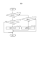
前記支援情報決定部113における前記運転支援情報170の算出方法を、図2のフローチャートを用いて説明する。
A method of calculating the driving support information 170 in the support information determination unit 113 will be described with reference to the flowchart of FIG.
ステップ201では、前記支援情報決定部113は、前記惰行位置161に値が設定されたか否かを判定する。前記惰行位置161に値が設定されている場合はステップ202へ、設定されていない場合はステップ204へ処理が遷移する。
In step 201, the support information determination unit 113 determines whether a value is set in the crawling position 161. When the value is set to the crawling position 161, the process proceeds to step 202, and when it is not set, the process proceeds to step 204.
ステップ202では、前記支援情報決定部113は、前記在線位置精度162を確認する(前記在線位置精度162が良好か否かを判定する)。在線位置精度が良好な場合はステップ203へ処理が遷移し、在線位置精度が悪化している場合は本フローを抜ける。
In step 202, the support information determination unit 113 checks the on-rail position accuracy 162 (determines whether the on-rail position accuracy 162 is good). If the on-line position accuracy is good, the process transitions to step 203. If the on-line position accuracy is degraded, the process exits this flow.
ステップ203では、前記支援情報決定部113は、前記惰行位置161を前記運転支援情報170として設定し、前記制駆動指令演算部114に送出する。
In step 203, the support information determination unit 113 sets the coasting position 161 as the driving support information 170 and sends it to the braking / driving instruction calculation unit 114.
ステップ204では、前記支援情報決定部113は、前記目標速度160に値が設定されたか否かを判定する。前記目標速度160に値が設定されている場合はステップ205へ処理が遷移し、設定されていない場合は、本処理フローを抜ける。
In step 204, the support information determination unit 113 determines whether a value has been set for the target speed 160. When a value is set to the target velocity 160, the process transitions to step 205, and when the value is not set, the process flow exits.
ステップ205では、前記支援情報決定部113は、前記目標速度161を前記運転支援情報170として設定し、前記制駆動指令演算部114に送出する。
In step 205, the support information determination unit 113 sets the target speed 161 as the driving support information 170 and sends it to the braking / driving instruction calculation unit 114.
本フローチャートによれば、一旦、在線位置精度が悪化して惰行位置の支援を中断した場合でも、再度、在線位置精度が良好な状態に戻った後は、本来の惰行位置の支援を再開することが可能であり、省エネ性の向上に寄与する。
According to this flowchart, even if the assistance for the crawling position is interrupted due to the deterioration of the accuracy on the railway position, the assistance for the crawling position should be resumed after returning to the state where the accuracy on the railway position is good again. Contributes to the improvement of energy saving.
以上が、前記支援情報決定部113における前記運転支援情報170の算出方法の説明である。
The above is the description of the calculation method of the driving support information 170 in the support information determination unit 113.
前記制駆動指令演算部114における前記制駆動指令180の算出方法を説明する。
A method of calculating the braking / driving command 180 in the braking / driving command calculation unit 114 will be described.
まず基本的に、前記制駆動指令演算部114は、前記車両速度151が、前記保安装置102から取得する前記制限速度171を超過しないように前記制駆動指令180を演算・出力する。また、図1には図示しないが、次駅の目標停止位置に向けて予め用意されているブレーキパターン(位置と速度で定義される)に沿って停止するように、前記制駆動指令180を演算・出力する。上記の前記制限速度171と前記ブレーキパターンを前記車両速度151が超過しない範囲において、前記制駆動指令演算部114は、前記運転支援情報170に基づいた前記制駆動指令180の算出を行う。
First, basically, the braking / driving command computation unit 114 computes / outputs the braking / driving command 180 so that the vehicle speed 151 does not exceed the speed limit 171 acquired from the security device 102. Also, although not shown in FIG. 1, the braking / driving command 180 is calculated so as to stop along the brake pattern (defined by position and speed) prepared in advance toward the target stop position of the next station. ·Output. The braking / driving command calculation unit 114 calculates the braking / driving command 180 based on the driving support information 170 in a range in which the vehicle speed 151 does not exceed the speed limit 171 and the brake pattern.
列車が駅を発車した後、前記制駆動指令演算部114は、前記運転支援情報170の内容を周期的に確認しながら力行し、列車を加速する。前記運転支援情報170に前記目標速度160が設定された場合には当該速度に前記車両速度151が追従するように前記制駆動指令180を演算する。その後、前記運転支援情報170に前記惰行位置161が設定された場合には、その時点から惰行を始める。場合によっては、力行・加速中に前記目標速度160の設定がないまま、前記運転支援情報170に前記惰行位置161が設定されることもあり、その場合は当該地点から惰行を開始する。
After the train leaves the station, the braking / driving command calculation unit 114 performs powering while periodically checking the content of the driving support information 170 to accelerate the train. When the target speed 160 is set in the driving support information 170, the braking / driving command 180 is calculated so that the vehicle speed 151 follows the speed. Thereafter, when the coasting position 161 is set in the driving support information 170, coasting starts from that point. In some cases, the coasting position 161 may be set in the driving support information 170 without setting the target speed 160 during power running and acceleration, in which case coasting is started from the point.
前記制限速度171によって、駅間に低い速度制限が存在する場合には、前記制駆動指令演算部114は、前記車両速度151が当該速度制限を超過しないように、前記制駆動指令180を算出する。速度制限が無くなったあとは、駅発車後と同様の流れである。
If a low speed limit exists between the stations according to the speed limit 171, the control / drive command calculation unit 114 calculates the control / drive command 180 so that the vehicle speed 151 does not exceed the speed limit. . After the speed limit disappears, the flow is the same as after leaving the station.
停止駅に近づいた際には、列車が定速走行中か惰行中かに関わらず、前記制駆動指令演算部114は、前記車両速度151が前記ブレーキパターンの速度を超過しないよう、前記制駆動指令180を算出する。
When approaching the stop station, regardless of whether the train is traveling at a constant speed or coasting, the braking / driving command calculation unit 114 prevents the vehicle speed 151 from exceeding the speed of the braking pattern. The command 180 is calculated.
前記制駆動指令演算部114において、目標とする速度(前記目標速度160や前記制限速度171)に前記車両速度151を追従させるための制御は、比例制御やファジー制御などの例が挙げられるが、本実施例においてその制御方式は問わない。
The control for causing the vehicle speed 151 to follow the target speed (the target speed 160 and the speed limit 171) in the braking / driving command calculation unit 114 may be exemplified by proportional control, fuzzy control, etc. There is no limitation on the control method in the present embodiment.
以上が、前記制駆動指令演算部114における前記制駆動指令180の算出方法の説明である。
The above is the description of the method of calculating the braking / driving command 180 in the braking / driving command calculation unit 114.
本実施例に記載の前記運転支援システム100によれば、列車の在線位置検知精度が悪化した場合であっても、定時性の悪化を抑制することができる。例を図10に示す。図10の(1)は、定速開始判定(目標速度提示)を示し、図10の(2)は、惰行開始判定(惰行開始位置提示)を示す。図10の符号11は、位置精度悪化(例:空転発生で走行距離が進んだ場合)、を示し、図10の符号12は、位置精度の悪化を検知(惰行中速度挙動より)、を示す。図10の例では、駅発車後の定速走行中に空転が発生し、在線位置の検知精度が悪化している。具体的には在線位置を進行方向前方に間違えて認識している状態である。この状態で駅中間での惰行を開始したため駅間後半の巡航速度が低下してしまっている。ここで、図4に示した、速度軌跡のずれに基づく方法で在線位置検知精度の悪化を検知している。その結果、以降の惰行支援が中止されて停止ブレーキ前の惰行は挿入されず、次駅への遅着の影響を抑制できている。
According to the driving support system 100 described in the present embodiment, it is possible to suppress the deterioration of the on-time performance even when the on-rail position detection accuracy is deteriorated. An example is shown in FIG. (1) of FIG. 10 shows a constant speed start determination (target speed presentation), and (2) of FIG. 10 shows a coasting start determination (coasting start position presentation). The code | symbol 11 of FIG. 10 shows position accuracy deterioration (example: when traveling distance advances by slippage occurrence), and the code | symbol 12 of FIG. 10 shows detection of deterioration of position accuracy (from coasting speed behavior). . In the example of FIG. 10, idling occurs during constant speed traveling after leaving the station, and detection accuracy of the on-rail position is deteriorated. Specifically, it is in a state in which the on-rail position is erroneously recognized in the forward direction of travel. In this state, the cruise speed in the second half of the station has been reduced because it started coasting in the middle of the station. Here, the deterioration of the on-rail position detection accuracy is detected by the method based on the deviation of the velocity locus shown in FIG. As a result, the subsequent coasting support is canceled and the coasting before the stop brake is not inserted, and the influence of the late arrival to the next station can be suppressed.
以上が実施例1の説明である。
The above is the description of the first embodiment.
本実施例では、本発明の運転支援システムによって手動での列車運転を支援する例を示す。本実施例に示す運転支援の方法によれば、列車の在線位置検知精度が悪化した場合にも、省エネ性と定時性の悪化を抑制した列車運行が可能となる。
In the present embodiment, an example is described in which manual train operation is supported by the operation support system of the present invention. According to the method of driving support shown in the present embodiment, it is possible to operate the train in which the deterioration of the energy saving performance and the on-time performance is suppressed even when the detection accuracy of the on-line position of the train is deteriorated.
はじめに、本実施例の運転支援システムのシステム構成を説明する。図11は、本実施例の運転支援システムのシステム構成を示す図である。
First, the system configuration of the driving support system of the present embodiment will be described. FIG. 11 is a diagram showing a system configuration of the driving support system of the present embodiment.
運転支援システム1100は、車両情報制御装置101から取得する情報に基づいて、運転支援を行う。前記運転支援システム1100が前記車両情報制御装置101から取得する情報は、残走行時分150と車両速度151と在線位置情報152と制駆動力情報153と想定走行パターン154と空転/滑走検知結果155である。
The driving support system 1100 performs driving support based on the information acquired from the vehicle information control device 101. The information acquired by the driving support system 1100 from the vehicle information control device 101 includes the remaining traveling time 150, the vehicle speed 151, the location information 152, the braking / driving force information 153, the assumed traveling pattern 154, and the slip / slip detection result 155. It is.
前記残走行時分150、前記車両速度151、前記在線位置情報152、前記制駆動力情報153、前記想定走行パターン154、前記空転/滑走検知結果155は実施例1に記載の通りである。
The remaining traveling time 150, the vehicle speed 151, the on-rail position information 152, the braking / driving force information 153, the assumed traveling pattern 154, and the slippage / slippage detection result 155 are as described in the first embodiment.
前記運転支援システム1100は、位置・速度予測部1115と、定速支援部110と、惰行支援部111と在線位置認識精度検出部112と、支援情報決定部113と表示器1114とから構成される。
The driving support system 1100 includes a position / speed prediction unit 1115, a constant speed support unit 110, a crawling support unit 111, a position recognition accuracy detection unit 112, a support information determination unit 113, and a display 1114. .
前記位置・速度予測部1115は、前記車両速度151と前記在線位置情報152と前記制駆動力情報153とを入力として、予測速度1163と予測位置1164を算出し、前記定速支援部110と前記惰行支援部111へ出力する。前記予測速度1163と前記予測位置1164の算出方法については後述する。
The position / speed prediction unit 1115 calculates the predicted speed 1163 and the predicted position 1164 by using the vehicle speed 151, the on-line position information 152 and the braking / driving force information 153 as input, and the constant speed support unit 110 It outputs to the crawling support unit 111. The method of calculating the predicted velocity 1163 and the predicted position 1164 will be described later.
前記定速支援部110は、前記残走行時分150と前記予測速度1163と前記予測位置1164とを入力として目標速度160を算出し、前記支援情報決定部113へ出力する。前記目標速度160の算出方法については後述する。
The constant speed support unit 110 receives the remaining travel time 150, the predicted speed 1163, and the predicted position 1164 as input, calculates a target speed 160, and outputs the target speed 160 to the support information determination unit 113. The method of calculating the target speed 160 will be described later.
前記惰行支援部111は、前記残走行時分150と前記予測速度1163と前記予測位置1164とを入力として惰行位置161を算出し、前記支援情報決定部113へ出力する。前記惰行位置161の算出方法については後述する。
The coasting support unit 111 receives the remaining travel time 150, the predicted speed 1163, and the predicted position 1164 as input, calculates a coasting position 161, and outputs the coasting position 161 to the support information determination unit 113. The calculation method of the crawling position 161 will be described later.
前記在線位置認識精度検出部112は、前記車両速度151と前記在線位置情報152と前記制駆動力情報153と前記想定走行パターン154と前記空転/滑走検知結果155と乗務員入力結果1171を入力として在線位置精度162を算出し、前記支援情報決定部113へ出力する。前記在線位置精度162の算出方法については後述する。
The on-rail position recognition accuracy detection unit 112 receives the vehicle speed 151, the on-rail position information 152, the braking / driving force information 153, the assumed traveling pattern 154, the idling / sliding detection result 155, and the crew input result 1171 as input. The position accuracy 162 is calculated and output to the support information determination unit 113. The method of calculating the on-rail position accuracy 162 will be described later.
前記支援情報決定部113は、前記目標速度160と前記惰行位置161と前記在線位置精度162とを入力として、運転支援情報170を算出し、前記表示器1114へ出力する。前記運転支援情報170の算出方法については後述する。
The support information determination unit 113 receives the target speed 160, the crawling position 161, and the on-rail position accuracy 162, calculates driving support information 170, and outputs the driving support information 170 to the display 1114. The method of calculating the driving support information 170 will be described later.
前記表示器1114は、前記運転支援情報170を入力として、運転士に対する運転支援内容を画面表示あるいは音声鳴動、もしくはその両方で教示する。運転支援内容教示の具体例は後述する。
The display 1114 receives the driving support information 170 and teaches the driving support content for the driver by screen display and / or sound ringing. A specific example of driving assistance content teaching will be described later.
以上が、本実施例の運転支援システム1100のシステム構成の説明である。
The above is the description of the system configuration of the driving support system 1100 of the present embodiment.
次に、本実施例の運転支援システム1100に含まれる、前記位置・速度予測部1115と前記定速支援部110と前記惰行支援部111と前記在線位置認識精度検出部112と前記支援情報決定部113と前記表示器1114における各出力データの算出方法を説明する。
Next, the position / speed prediction unit 1115, the constant-speed support unit 110, the coasting support unit 111, the on-rail position recognition accuracy detection unit 112, and the support information determination unit included in the driving support system 1100 of the present embodiment. The calculation method of each output data in 113 and the said display 1114 is demonstrated.
前記位置・速度予測部1115は、当該列車の所定時間後の速度と位置を予測する。これは、手動運転における運転支援という機能の特性上、乗務員に対して実際に必要となる運転操作タイミングよりも早いタイミングで運転操作内容を教示する必要があるからである。
The position / speed prediction unit 1115 predicts the speed and position of the train after a predetermined time. This is because it is necessary to teach the driving operation contents at a timing earlier than the driving operation timing actually required for the crew due to the characteristic of the function of driving support in the manual driving.
速度と位置の予測方法の一例として、前記位置・速度予測部1115は、前記車両速度151と前記在線位置情報152を基準に、それから先の所定時間後まで前記制駆動力情報153が続いたと仮定して、前記予測速度1163と前記予測位置1164を計算する。
As an example of the speed and position prediction method, the position / speed prediction unit 1115 assumes that the braking / driving force information 153 continues until a predetermined time after the vehicle speed 151 and the on-rail position information 152 as a reference. Then, the predicted velocity 1163 and the predicted position 1164 are calculated.
予測の計算過程では、車両の制駆動特性や路線条件、あるいは制限速度情報を加味することで、より精度の良い予測が可能となる(これらの付加情報は図示しない)。また、予測用の前記所定時間は乗務員が支援内容を知覚してから余裕を持って操作に移ることができるように決められるものである。
In the process of calculation of prediction, more accurate prediction is possible by taking into consideration the control / drive characteristics of the vehicle, route conditions, or speed limit information (these additional information are not shown). Further, the predetermined time for prediction is determined so that the crew can shift to the operation with a margin after perceiving the content of the support.
前記定速支援部110における前記目標速度160の算出過程は、実施例1における前記車両速度151と前記在線位置情報152の代わりに、本実施例の前記予測速度1163と前記予測位置1164を用いることで算出される。具体的な算出方法については実施例1に記載の通りである。
The calculation process of the target speed 160 in the constant speed support unit 110 uses the predicted speed 1163 and the predicted position 1164 in the present embodiment instead of the vehicle speed 151 and the line location information 152 in the first embodiment. Calculated by The specific calculation method is as described in the first embodiment.
前記惰行支援部111における前記惰行位置161の算出過程は、実施例1における前記車両速度151と前記在線位置情報152の代わりに、本実施例の前記予測速度1163と前記予測位置1164を用いることで算出される。具体的な算出方法については実施例1に記載の通りである。
The calculation process of the coasting position 161 in the coasting support unit 111 uses the predicted speed 1163 and the predicted position 1164 of the present embodiment instead of the vehicle speed 151 and the on-rail position information 152 in the first embodiment. It is calculated. The specific calculation method is as described in the first embodiment.
前記在線位置認識精度検出部112が出力する前記在線位置精度162とは、列車の真の位置と前記在線位置情報152との整合性に関する検出結果である。様々な検出方法があり、複数の検出方法を組み合わせることで、より正確に前記在線位置精度162が検出できる。
The on-rail position accuracy 162 outputted by the on-rail position recognition accuracy detection unit 112 is a detection result regarding the consistency between the true position of the train and the on-rail position information 152. There are various detection methods, and the on-rail position accuracy 162 can be detected more accurately by combining a plurality of detection methods.
実施例1の図3、図4、図5、図6で説明した検出方法は本実施例でも適用可能である。
The detection method described in FIG. 3, FIG. 4, FIG. 5, and FIG. 6 of the first embodiment is also applicable to this embodiment.
前記在線位置精度162の検出方法の他の例として、前記乗務員入力結果1171に基づく方法を説明する。この方法では、乗務員が自列車の在線位置検出結果に疑問を持った際に、ユーザインタフェースを通して、その旨をシステム側に通知する。具体的には図7に示すように運転支援用画面に専用のボタンを設けて通知を可能にすることが考えられる。
As another example of the detection method of the on-rail position accuracy 162, a method based on the crew input result 1171 will be described. In this method, when a crew member has a question about the on-rail position detection result of the own train, the system side is notified of that through the user interface. Specifically, as shown in FIG. 7, it is conceivable to provide a dedicated button on the driving support screen to enable notification.
乗務員からの通知の方法はこれに限らない。これらの通知が有った場合に、前記在線位置精度162が悪化したという判定がなされる。なお、同様のユーザインタフェースを用いて、在線位置認識の精度が回復したことを乗務員から入力可能としてもよい。
The method of notification from the crew is not limited to this. When these notifications are received, it is determined that the on-rail position accuracy 162 has deteriorated. The same user interface may be used to allow the crew to input that the accuracy of the on-rail position recognition has recovered.
以上が、前記在線位置認識精度検出部112における前記在線位置精度162の検出方法の例であるが、前記在線位置精度162の検出方法はこれらに限らないことは言うまでもない。
The above is the example of the detection method of the on-line position accuracy 162 in the on-line position recognition accuracy detection unit 112, but it goes without saying that the detection method of the on-line position accuracy 162 is not limited thereto.
前記支援情報決定部113における前記運転支援情報170の算出方法は実施例1に記載の通りである。
The calculation method of the driving support information 170 in the support information determination unit 113 is as described in the first embodiment.
前記表示器1114では、前記運転支援情報170に従って、乗務員に対する支援内容を教示する。具体例として、運転操作内容を教示する方法が挙げられる。
The display 1114 teaches support content for the crew in accordance with the driving support information 170. As a specific example, there is a method of teaching the contents of driving operation.
図12は、運転台に設置された前記表示器1114に、運転操作内容が表示されている例を示す。前記運転支援情報170に前記目標速度160が設定されている場合に「87km/h定速」、前記惰行位置161が設定されている場合に「あと●mでノッチオフ」といった運転操作内容が表示される。画面表示以外に音声鳴動での教示も可能であり、両者を併用することも考えられる。
FIG. 12 shows an example in which the content of the driving operation is displayed on the display 1114 installed in the cab. When the target speed 160 is set in the driving support information 170, driving operation details such as "87 km / h constant speed", and when the coasting position 161 is set, "notch off at -m" are displayed. Ru. In addition to the screen display, teaching by sounding is also possible, and it is conceivable to use both in combination.
また、図12の前記表示器1114には、惰行支援中止を指示するボタンが用意されており、これを扱った結果が前記乗務員入力結果1171に反映される。当該ボタンが扱われた例を図13に示す。図13では前記乗務員入力結果1171の入力に基づいて、惰行支援がなされない状態へと遷移している。
Further, the display 1114 in FIG. 12 is provided with a button for instructing the suspension support cancellation, and the result of handling this is reflected in the crew input result 1171. An example in which the button is handled is shown in FIG. In FIG. 13, on the basis of the input of the crew input result 1171, a transition is made to a state where the coasting support is not provided.
なお、次駅到着時には、トランスポンダ等によって前記在線位置情報152は補正されることが一般的であり、そのタイミングで惰行支援中止モードからは抜けることが望ましい。
In addition, when arriving at the next station, the on-rail position information 152 is generally corrected by a transponder or the like, and it is desirable to exit from the coasting support cancellation mode at that timing.
本実施例に記載の前記運転支援システム1100によれば、列車の在線位置検知精度が悪化した場合であっても、定時性および省エネ性の悪化を抑制することができる。定時性の悪化抑制については実施例1で記載したとおりであるが、本実施例に記載した手動運転の支援に関しては、定時性の悪化抑制がシステム側で担保されることにより、乗務員による遅れ回復を目的とした過剰な力行操作を抑制することができ、省エネ性の悪化を抑制することができる。
According to the driving support system 1100 described in the present embodiment, it is possible to suppress the deterioration of the on-time performance and the energy saving performance even when the on-rail position detection accuracy is deteriorated. Although the suppression of deterioration of the scheduled operation is as described in the first embodiment, the system side guarantees the suppression of the deterioration of the scheduled operation with respect to the support of the manual operation described in the present embodiment, so that the delay recovery by the crew is recovered. It is possible to suppress excessive powering operations aimed at reducing the energy saving performance.
以上が実施例2の説明である。
The above is the description of the second embodiment.
100・・・運転支援システム
101・・・車両情報制御装置
102・・・保安装置
103・・・制駆動装置
110・・・定速支援部
111・・・惰行支援部
112・・・在線位置認識精度検出部
113・・・支援情報決定部
114・・・制駆動指令演算部
150・・・残走行時分
151・・・車両速度
152・・・在線位置情報
153・・・制駆動力情報
154・・・想定走行パターン
155・・・空転/滑走検知結果
160・・・目標速度
161・・・惰行位置
162・・・在線位置精度
170・・・運転支援情報
171・・・制限速度
180・・・制駆動指令
1100・・・運転支援システム
1114・・・表示器
1115・・・位置・速度予測部
1163・・・予測速度
1164・・・予測位置
1171・・・乗務員入力結果 100 ... drivingsupport system 101 ... vehicle information control device 102 ... security device 103 ... braking and driving device 110 ... constant speed support unit 111 ... coasting support unit 112 ... presence position recognition Accuracy detection unit 113 · · · Support information determination unit 114 · · · · · · driving control command calculation unit 150 · · · · · remaining travel time 151 · · · vehicle speed 152 · · · · location information 153 · · · driving force information 154 · · · · · · · · · · · · · · · · · · · · · · · · · · · · · · · · · • • • • • • • • • • • • • • • • • • • • • • • • • • • • • • • • • • • • • • • • • • • • • • • • • • • • • • • • • • • • • • • • • • • • • • • • • • • • • • • • • • • • • · Driving control system 1100 · · · Driving support system 1114 · · · Display 1115 · · · Position · speed prediction unit 1163 · · · predicted speed 1164 · · · predicted position 1171 · · · crew input results
101・・・車両情報制御装置
102・・・保安装置
103・・・制駆動装置
110・・・定速支援部
111・・・惰行支援部
112・・・在線位置認識精度検出部
113・・・支援情報決定部
114・・・制駆動指令演算部
150・・・残走行時分
151・・・車両速度
152・・・在線位置情報
153・・・制駆動力情報
154・・・想定走行パターン
155・・・空転/滑走検知結果
160・・・目標速度
161・・・惰行位置
162・・・在線位置精度
170・・・運転支援情報
171・・・制限速度
180・・・制駆動指令
1100・・・運転支援システム
1114・・・表示器
1115・・・位置・速度予測部
1163・・・予測速度
1164・・・予測位置
1171・・・乗務員入力結果 100 ... driving
Claims (11)
- 列車の駅間走行中における運転操作を支援する運転支援システムであって、前記列車の在線位置に応じた目標速度を決定する定速支援部と、前記列車の在線位置に応じた惰行位置を決定する惰行支援部と、前記列車の在線位置の精度である在線位置精度を出力する在線位置認識精度検出部と、運転支援情報を決定する支援情報決定部を備え、前記支援情報決定部は、前記在線位置精度に応じて前記目標速度と前記惰行位置から前記運転支援情報を作成することを特徴とする運転支援システム。 A driving support system for supporting a driving operation while traveling between stations of a train, comprising: a constant speed support unit that determines a target speed according to the location of the train; and a coasting position according to the location of the train And a support information determination unit for determining driving support information, and the support information determination unit is configured to: A driving support system, wherein the driving support information is created from the target speed and the coasting position according to the on-rail position accuracy.
- 請求項1に記載の運転支援システムであって、前記支援情報決定部は、前記在線位置精度が良好である場合に前記目標速度と前記惰行位置から前記運転支援情報を作成し、前記在線位置精度が良好ではない場合に前記目標速度のみで構成される前記運転支援情報を作成すること、を特徴とする運転支援システム。 The driving support system according to claim 1, wherein the support information determination unit generates the driving support information from the target speed and the crawling position when the on-rail position accuracy is good, and the on-rail position accuracy The driving assistance system, wherein the driving assistance information composed only of the target speed is created when is not good.
- 請求項1または請求項2のいずれか一つに記載の運転支援システムであって、前記在線位置認識精度検出部は、前記在線位置の変化率に基づいて前記在線位置精度が良好であるかどうか判定することを特徴とする運転支援システム。 The driving support system according to any one of claims 1 and 2, wherein the on-rail position recognition accuracy detection unit is configured to determine whether the on-rail position accuracy is good based on a change rate of the on-rail position. A driving support system characterized by determining.
- 請求項1乃至請求項3のいずれか一つに記載の運転支援システムであって、前記在線位置認識精度検出部は、前記在線位置の変化に基づいて算出される加速度が、前記列車の駆動力により発生しうる最大の加速度以下のとき前記在線位置精度が良好であると判定し、前記在線位置の変化に基づいて算出される加速度が、前記列車の駆動力により発生しうる最大の加速度を超えるとき前記在線位置精度が良好ではないと判定することを特徴とする運転支援システム。 The driving support system according to any one of claims 1 to 3, wherein the on-rail position recognition accuracy detection unit is configured to calculate an acceleration calculated based on a change in the on-rail position as a driving force of the train. It is determined that the on-rail position accuracy is good when the acceleration is less than the maximum acceleration that can be generated, and the acceleration calculated based on the change in the on-rail position exceeds the maximum acceleration that can be generated by the driving force of the train It is determined that the on-rail position accuracy is not good when the driving support system.
- 請求項1乃至請求項4のいずれか一つに記載の運転支援システムであって、前記在線位置認識精度検出部は、走行中の速度軌跡に基づいて前記在線位置精度が良好であるかどうか判定することを特徴とする運転支援システム。 The driving support system according to any one of claims 1 to 4, wherein the on-rail position recognition accuracy detection unit determines whether the on-rail position accuracy is good based on a speed locus during traveling. A driving support system characterized by having.
- 請求項1乃至請求項5のいずれか一つに記載の運転支援システムであって、前記在線位置認識精度検出部は、複数の位置検知手段による検知結果の照合結果に基づいて前記在線位置精度が良好であるかどうか判定することを特徴とする運転支援システム。 The driving support system according to any one of claims 1 to 5, wherein the on-rail position recognition accuracy detection unit detects the on-rail position accuracy based on a comparison result of detection results by a plurality of position detection units. A driving support system characterized by determining whether it is good.
- 請求項1乃至請求項6のいずれか一つに記載の運転支援システムであって、前記在線位置認識精度検出部は、空転または滑走の履歴に基づいて前記在線位置精度が良好であるかどうか判定することを特徴とする運転支援システム。 The driving support system according to any one of claims 1 to 6, wherein the on-rail position recognition accuracy detection unit determines whether the on-rail position accuracy is good based on a history of idling or sliding. A driving support system characterized by having.
- 請求項1乃至請求項7のいずれか一つに記載の運転支援システムであって、前記在線位置認識精度検出部は、乗務員からの入力に基づいて前記在線位置精度が良好であるかどうか判定することを特徴とする運転支援システム。 The driving support system according to any one of claims 1 to 7, wherein the on-rail position recognition accuracy detection unit determines whether or not the on-rail position accuracy is good based on an input from a crew member. Driving support system characterized by.
- 請求項1乃至請求項8のいずれか一つに記載の運転支援システムであって、前記在線位置認識精度検出部は、前記列車の在線位置を補正したとき前記在線位置精度を良好であると判定することを特徴とする運転支援システム。 The driving support system according to any one of claims 1 to 8, wherein the on-rail position recognition accuracy detection unit determines that the on-rail position accuracy is good when the on-rail position of the train is corrected. A driving support system characterized by having.
- 請求項1乃至請求項9のいずれか一つに記載の運転支援システムであって、前記運転支援情報に基づき、制駆動装置への制駆動指令を計算する制駆動指令演算部を備えることを特徴とする運転支援システム。 The driving support system according to any one of claims 1 to 9, further comprising: a braking / driving command calculation unit configured to calculate a braking / driving command to a braking / driving device based on the driving support information. Driving support system.
- 請求項1乃至請求項10のいずれか一つに記載の運転支援システムであって、前記運転支援情報に基づき、目標速度と惰行タイミングを表示する表示器を備えることを特徴とする運転支援システム。 The driving support system according to any one of claims 1 to 10, further comprising a display for displaying the target speed and the coasting timing based on the driving support information.
Applications Claiming Priority (2)
| Application Number | Priority Date | Filing Date | Title |
|---|---|---|---|
| JP2018-000050 | 2018-01-04 | ||
| JP2018000050A JP6914203B2 (en) | 2018-01-04 | 2018-01-04 | Driving support system |
Publications (1)
| Publication Number | Publication Date |
|---|---|
| WO2019135310A1 true WO2019135310A1 (en) | 2019-07-11 |
Family
ID=67144446
Family Applications (1)
| Application Number | Title | Priority Date | Filing Date |
|---|---|---|---|
| PCT/JP2018/040006 WO2019135310A1 (en) | 2018-01-04 | 2018-10-26 | Operation assistance system |
Country Status (2)
| Country | Link |
|---|---|
| JP (1) | JP6914203B2 (en) |
| WO (1) | WO2019135310A1 (en) |
Families Citing this family (2)
| Publication number | Priority date | Publication date | Assignee | Title |
|---|---|---|---|---|
| JP7426256B2 (en) * | 2020-02-27 | 2024-02-01 | 株式会社日立製作所 | Energy-saving driving support system and its method |
| JP7303142B2 (en) * | 2020-03-17 | 2023-07-04 | 株式会社日立製作所 | Driving support device and driving support method |
Citations (3)
| Publication number | Priority date | Publication date | Assignee | Title |
|---|---|---|---|---|
| JP2015043673A (en) * | 2013-08-26 | 2015-03-05 | 株式会社東芝 | Train control device |
| WO2016121606A1 (en) * | 2015-01-28 | 2016-08-04 | 三菱電機株式会社 | Train car position detecting device |
| JP2017085688A (en) * | 2015-10-23 | 2017-05-18 | 株式会社日立製作所 | Automatic train operation device and train operation support device |
-
2018
- 2018-01-04 JP JP2018000050A patent/JP6914203B2/en active Active
- 2018-10-26 WO PCT/JP2018/040006 patent/WO2019135310A1/en active Application Filing
Patent Citations (3)
| Publication number | Priority date | Publication date | Assignee | Title |
|---|---|---|---|---|
| JP2015043673A (en) * | 2013-08-26 | 2015-03-05 | 株式会社東芝 | Train control device |
| WO2016121606A1 (en) * | 2015-01-28 | 2016-08-04 | 三菱電機株式会社 | Train car position detecting device |
| JP2017085688A (en) * | 2015-10-23 | 2017-05-18 | 株式会社日立製作所 | Automatic train operation device and train operation support device |
Also Published As
| Publication number | Publication date |
|---|---|
| JP2019122131A (en) | 2019-07-22 |
| JP6914203B2 (en) | 2021-08-04 |
Similar Documents
| Publication | Publication Date | Title |
|---|---|---|
| CN102470868B (en) | Vehicle control device, vehicle control method, and vehicle control system | |
| KR101079903B1 (en) | Apparatus and method for controlling speed in Automatic Train Operation | |
| KR102269924B1 (en) | Train control device, method and recording medium | |
| JP3234925B2 (en) | Train control device | |
| KR101866610B1 (en) | Apparatus for Warning of Exceeding Speed Limit in Railway Vehicles | |
| US10150491B2 (en) | Device and method for controlling train | |
| WO2019135310A1 (en) | Operation assistance system | |
| US10336324B2 (en) | Calculation of the time to collision for a vehicle | |
| JP2001154733A (en) | Method and device for controlling automatic travel of vehicle | |
| JP4005541B2 (en) | Train travel control system and train travel control method | |
| JP2017085688A (en) | Automatic train operation device and train operation support device | |
| EP2979952B1 (en) | Method for reducing the delay of a rail vehicle to reach a destination | |
| EP3192717A1 (en) | Operation control system | |
| CN111361606A (en) | Punctual arrival control method, device, medium and equipment for locomotive | |
| JP5512193B2 (en) | Train control method, train control device, and vehicle | |
| JP2006074876A (en) | Home position stoppage automatic controller for vehicle | |
| JP2008187761A (en) | Train control device | |
| JP5364682B2 (en) | Train speed control method and apparatus | |
| JPH11234813A (en) | Automatic operation controller for train | |
| JP2019089449A (en) | Device, method and program for train travel control | |
| JP2006123568A (en) | Controlled object judging device for vehicle | |
| JP2005280542A (en) | Atc/o device | |
| JP2006290149A (en) | Traveling controller for vehicle | |
| JP5274873B2 (en) | Automatic train control device and automatic train control method | |
| WO2018163508A1 (en) | Train control system, train control method, and train on-board device |
Legal Events
| Date | Code | Title | Description |
|---|---|---|---|
| 121 | Ep: the epo has been informed by wipo that ep was designated in this application |
Ref document number: 18898585 Country of ref document: EP Kind code of ref document: A1 |
|
| NENP | Non-entry into the national phase |
Ref country code: DE |
|
| 122 | Ep: pct application non-entry in european phase |
Ref document number: 18898585 Country of ref document: EP Kind code of ref document: A1 |