JP2019089449A - Device, method and program for train travel control - Google Patents
Device, method and program for train travel control Download PDFInfo
- Publication number
- JP2019089449A JP2019089449A JP2017219385A JP2017219385A JP2019089449A JP 2019089449 A JP2019089449 A JP 2019089449A JP 2017219385 A JP2017219385 A JP 2017219385A JP 2017219385 A JP2017219385 A JP 2017219385A JP 2019089449 A JP2019089449 A JP 2019089449A
- Authority
- JP
- Japan
- Prior art keywords
- train
- speed
- operation curve
- stations
- time
- Prior art date
- Legal status (The legal status is an assumption and is not a legal conclusion. Google has not performed a legal analysis and makes no representation as to the accuracy of the status listed.)
- Pending
Links
Images


Abstract
Description
本発明の実施形態は、列車走行制御装置、方法及びプログラムに関する。 Embodiments of the present invention relate to a train travel control device, method and program.
鉄道は計画されたダイヤに従って、乗客を運ぶ定時性の高い公共交通機関である。従って、従来は如何に定時性を確保しながら運行するかが重要な課題であった。
しかし、近年の電力不足からエネルギー効率のよい鉄道に対しても更なる省エネルギー(以下、単に省エネという。)が求められている。
The railway is a high-speed public transportation that carries passengers according to the planned schedule. Therefore, conventionally, how to operate while securing on-time characteristics has been an important issue.
However, due to power shortages in recent years, further energy saving (hereinafter simply referred to as energy saving) is also required for energy efficient railways.
ところで、列車の運行において遅れが発生した場合、その遅延した時間を回復させて定時性を確保するために列車の走行時間を計画ダイヤの走行時間よりも短くすることがある。このような場合に、先行列車も遅延を起こしている場合には、先行列車の走行状態に影響を受ける信号により、駅間で停止を余儀なくされる虞があった。 By the way, when a delay occurs in the operation of a train, the travel time of the train may be made shorter than the travel time of the plan diagram in order to recover the delayed time and secure the on-time performance. In such a case, when the preceding train is also delayed, there is a possibility that a stop may be forced between the stations by a signal affected by the traveling state of the preceding train.
駅間で停止してしまった場合には、再度加速する必要が生じ、加速のためにエネルギーが消費され、エネルギー消費効率が悪化することとなっていた。 In the case of stopping between stations, it is necessary to accelerate again, energy is consumed for acceleration, and energy consumption efficiency is deteriorated.
一方、駅間で停止をして無駄にエネルギーを消費することを回避するため、予めゆっくり走行することも考えられるが、当該列車が遅延している場合には遅延を回復することができないとともに、当該列車の後続列車の遅延を大きくする原因ともなり得ていた。 On the other hand, it is conceivable to travel slowly in advance to avoid wasting energy by stopping between stations, but it is not possible to recover the delay if the train is delayed, It could also be a cause of the delay of the following train of the train concerned.
このような状況において駅間停止を防止するためにリアルタイムで運転曲線を作成する技術が提案されている。 In order to prevent the stop between stations in such a situation, the technique which creates a driving curve in real time is proposed.
しかしながら、リアルタイムで運転曲線を作成する場合、例えば、運転曲線の作成に1秒かかるとすると、現在時刻での速度が108km/hであれば、1秒間でおよそ30mも進んでしまうため、誤差が生じ、所望の制御が行えない虞があった。 However, when creating a driving curve in real time, for example, if it takes 1 second to create a driving curve, if the speed at the current time is 108 km / h, the error will increase by about 30 m in 1 second As a result, there is a risk that the desired control can not be performed.
そこで本発明は、リアルタイムに運転曲線を作成することなく、定時性確保と省エネの両立を実現することが可能な列車走行制御装置、方法及びプログラムを提供することを目的としている。 Then, this invention aims at providing the train travel control apparatus, method, and program which can implement | achieve coexistence of fixed time property ensuring and energy saving, without producing a driving curve in real time.
実施形態の列車走行制御装置の運転曲線作成部は、予め運転曲線データベースに格納された所定の駅間の基準運転曲線データに基づいて列車の計画運転曲線を作成する。
これにより、速度変更設定部は、計画運転曲線に基づいて、制御対象列車が当該制御対象列車に先行して運行される先行列車の走行状態に起因して当該制御対象列車が現在駅から次の停車駅に至る駅間で停車する虞が生じた場合に、駅間での停車を回避するために制御対象列車の速度を、計画運転曲線で設定される速度より低速側に設定する。
The operation curve creation unit of the train travel control device of the embodiment creates a planned operation curve of the train based on reference operation curve data between predetermined stations stored in advance in the operation curve database.
As a result, the speed change setting unit causes the control target train to follow the current station based on the running state of the preceding train in which the control target train is operated prior to the control target train based on the planned operation curve. When there is a possibility of stopping between the stations reaching the stopping station, the speed of the train to be controlled is set to a lower speed side than the speed set by the planned operation curve in order to avoid stopping between the stations.
次に図面を参照して実施形態について説明する。
[1]第1実施形態
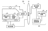
図1は、列車運行システムの概要構成ブロック図である。
列車運行システム100は、列車11と、列車11の進行方向において先行する先行列車11Pと、複数の軌道回路15と、複数の軌道回路15と伝送路16を介して接続される運行管理システム101と、を備えている。
Embodiments will now be described with reference to the drawings.
[1] First Embodiment FIG. 1 is a schematic block diagram of a train operation system.
The
図2は、実施形態の列車駅間走行制御装置を含む列車運行システムの詳細構成ブロック図である。
図2において、図1と同様の部分には同一の符号を付すものとする。
FIG. 2 is a detailed configuration block diagram of a train operation system including the inter-train station travel control device according to the embodiment.
In FIG. 2, the same parts as in FIG. 1 are given the same reference numerals.
列車運行システム100は、大別すると、列車11(及び先行列車11P)に対して架線12及び線路13を介して電力を供給する変電所14と、列車11の運行状態を監視するための軌道回路15と、伝送路16を介して変電所14及び軌道回路15と通信可能に接続され、列車11の運行管理を行う運行管理装置17と、運行管理装置17の制御下で地上送受信装置18を介して列車11に搭載された後述の運転支援装置22を用いて駅間における列車の走行制御を行う列車走行制御装置19と、を備えている。
The
この場合において、運行管理装置17及び列車走行制御装置19は、運行指令所に設置されており、運行管理装置17、地上送受信装置18及び列車走行制御装置19は、運行管理システム101を構成している。
In this case, the
列車11は、地上送受信装置18との間で通信を行う車上送受信装置21と、運転士に対する運転支援を行う運転支援装置22と、を備えている。そして、列車11の車上送受信装置21は、停車駅の出発時刻や到着時刻、駅間の走行実績等を地上の運行管理装置17に送信し、地上の列車走行制御装置19から出発時刻や運転支援装置22に表示する運転支援情報等を受信する。
The
変電所14は、列車の走行や地上にある保安設備、駅の設備などに供給する電力を管理している。また、変電所14の電力管理情報は、伝送路16を介して、運転指令所に設置された列車走行制御装置19において取得可能となっている。
The
軌道回路15は、列車の在線状況を確認するためのものである。軌道回路15によれば、同一の閉塞区間に複数の列車11が存在できないように制御を行うことができ、列車11の衝突防止などの保安を担保することができる。
The
伝送路16は、いわゆる通信ネットワークとして構成されており、列車11の運行状況や変電所の使用電力の状況を運行管理装置17に通知するための通信線路を構成している。
運行管理装置17は、上述した軌道回路15からの情報などを用いて、列車11の在線状況を管理する。
The
The
地上送受信装置18は、列車走行制御装置19が作成した当該列車の速度変更情報を車上送受信装置21に送信する。また、地上送受信装置18は、車上送受信装置21から速度変更情報を受信する。
The ground transmission /
列車走行制御装置19は、当該列車11の運行状態に応じて、運転支援装置22を介して駅間における列車の走行制御を行う。
The train
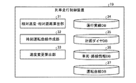
図3は、列車走行制御装置の機能構成図である。
列車走行制御装置19は、大別すると、相対速度・相対距離算出部31と、時刻運転曲線作成部32と、速度変更算出部33と、運行実績データベース(DB)34と、計画ダイヤデータベース(DB)35と、車両・路線情報データベース(DB)36と、運転曲線データベース(DB)37と、を備えている。
FIG. 3 is a functional configuration diagram of the train travel control device.
The train
相対速度・相対距離算出部31は、走行中の列車11に対して、現在走行している駅間の現在時刻での速度および位置と、当該列車11の先行列車11Pの現在時刻での速度および位置から相対速度および相対距離を算出する。
The relative speed / relative distance calculation unit 31 calculates the speed and position at the current time between the stations currently being traveled, the speed at the current time of the preceding
時刻運転曲線作成部32は、計画ダイヤデータベース35に格納されている当該列車の列番と、現在停車している、あるいは、直前に停車していた駅を特定するための駅特定情報(駅ID)から計画ダイヤ上の出発する時刻と計画ダイヤ上の次停車駅に到着する時刻を参照して、当該駅間の走行時間を算出する。続いて時刻運転曲線作成部32は、算出した当該駅間の走行時間に基づいて運転曲線データベース37から現在駅の駅特定情報(駅ID)、次到着駅の駅特定情報(駅ID)および前出走行時間と同じ走行時間の基準運転曲線データを検索する。そして時刻運転曲線作成部32は、計画ダイヤデータベース35に記録されている現在停車している、あるいは、直前に停車していた駅の出発時刻に各経過時刻を加算することで当該列車11の計画ダイヤの時刻に対する速度、位置等の情報を持つ時刻運転曲線データを作成する。
The time driving curve creation unit 32 is station identification information (station ID for identifying the train number of the relevant train stored in the
図4は、時刻運転曲線データの一例の説明図である。
時刻運転曲線データは、図4に示すように、当該列車11が直前に停止した駅(出発駅)からダイヤ上出発する予定の時刻(図4の例の場合、8時00分00秒[8:00:00])に対応させて、当該時刻における速度を格納した速度データ、当該時刻における出発駅からの距離を表す位置データ、各走行位置における瞬時消費電力を表す現在電力データ及び各走行位置に至るまでの累計消費電力量を表す累計電力量データを備えている。
FIG. 4 is an explanatory diagram of an example of time operation curve data.
The time operation curve data is, as shown in FIG. 4, the time when the
図5は、運転曲線データベース(DB)の具体例の説明図である。
ところで、時刻運転曲線データは、各列番での駅間毎に作成するが、それぞれ個別にデータを持つと膨大な量になる。そこで時刻運転曲線データを作成するために必要な最低限のデータが図5のデータである。図5のデータは駅を出発してからの経過時間で記載してあるため、出発時刻がわかれば、その時刻を各時間列に加算することで図4に示した時刻運転曲線データを作成することができる。そのため、ある1つの駅間に着目すれば、走行時間が異なる基準運転曲線データのみ運転曲線DBに記録すればよい。
FIG. 5 is an explanatory diagram of a specific example of the driving curve database (DB).
By the way, although time operation curve data is created for every station in each row number, if it has data individually, it will be a huge amount. Therefore, the minimum data required to create the time operation curve data is the data of FIG. Since the data in FIG. 5 is described by the elapsed time since leaving the station, if the departure time is known, the time operation curve data shown in FIG. 4 is created by adding the time to each time sequence. be able to. Therefore, if attention is paid to one certain station, only reference driving curve data having different traveling times may be recorded in the driving curve DB.
運転曲線データベース(DB)37は、時刻運転曲線作成部32が作成した運転曲線及びダイヤ上の走行時間で予め計算されている運転曲線が記録されているデータベースである。 The driving curve database (DB) 37 is a database in which a driving curve calculated by the time driving curve generation unit 32 and a driving curve calculated in advance by a traveling time on a diamond are recorded.
ここで、運転曲線データベース(DB)37の具体例について説明する。
運転曲線データベース(DB)37は、出発駅を特定するための出発駅ID及び到着駅を特定するための到着駅IDで特定される特定の駅間について、走行開始後の経過時間を表す時間データ、時間データに対応する車両の速度を表す速度データ、出発駅を基準とする位置(走行位置)を表す位置データ、各走行位置における瞬時消費電力を表す現在電力データ及び各走行位置に至るまでの累計消費電力量を表す累計電力量データを備えている。
なお、現在電力データに関しては、乗車率を考慮して算出され、乗車率は、例えば、車体と台車との間に設けられたロードセンサの出力に基づいて算出される。
Here, a specific example of the driving curve database (DB) 37 will be described.
The driving curve database (DB) 37 is time data representing an elapsed time after the start of traveling for a specific station identified by a departure station ID for identifying a departure station and an arrival station ID for identifying an arrival station. Speed data representing the speed of the vehicle corresponding to the time data, position data representing the position (traveling position) relative to the departure station, current power data representing instantaneous power consumption at each traveling position, and each traveling position Cumulative power consumption data representing cumulative power consumption is provided.
The current power data is calculated in consideration of the boarding rate, and the boarding rate is calculated based on, for example, the output of a load sensor provided between the vehicle body and the carriage.
また、速度変更算出部33は、相対速度・相対距離算出部31で算出した相対速度及び相対距離並びに時刻運転曲線作成部32で算出した時刻運転曲線データを用いて、当該列車11が走行中の駅間でのダイヤで設定されている計画上の走行位置、現在の位置、速度及び先行列車との相対速度、相対位置に基づいて現在時刻以降の速度変更のための情報を算出する。
Further, the speed change calculation unit 33 uses the relative speed and relative distance calculated by the relative speed / relative distance calculation unit 31 and the time operation curve data calculated by the time operation curve creation unit 32 so that the
運行実績データベース(DB)34は、列車運行の実績値を記録するデータベースである。具体的には、運行実績データベース34には、所定の時間毎の時刻に対する速度、キロ程位置、瞬時電力、ノッチ番号等の組合せで表されるデータ群が記録されている。
計画ダイヤデータベース(DB)35は、列番毎に各駅の出発時刻、到着時刻等が記載されているデータベースである。
The operation result database (DB) 34 is a database for recording the actual value of the train operation. Specifically, in the operation result database 34, a data group represented by a combination of the speed, the kilometer position, the instantaneous power, the notch number and the like with respect to the time every predetermined time is recorded.
The plan diagram database (DB) 35 is a database in which departure times, arrival times, and the like of each station are described for each row number.
車両・路線情報データベース(DB)36は、各車両の速度に対する引張力、ブレーキ力および入力電流等のデータや当該路線のキロ程位置に対する勾配、制限速度、線路の曲率半径などの路線に関する情報が保存されているデータベースである。 The vehicle and route information database (DB) 36 contains data such as tensile force, braking force and input current with respect to the velocity of each vehicle, and information about the route such as slope with respect to the kilometer position of the route, speed limit, and track radius of curvature. It is a stored database.
次に実施形態の動作を説明する。
図6は、実施形態の列車駅間走行制御装置の処理フローチャートである。
図6に示される処理は、一定時間間隔(例えば、10秒毎)または閉塞境界を通過したタイミングなどのイベント発生時に制御対象の列車に対して処理が開始される。
Next, the operation of the embodiment will be described.
FIG. 6 is a process flowchart of the inter-train station travel control device according to the embodiment.
The process shown in FIG. 6 is started for a train to be controlled when an event occurs, such as at a predetermined time interval (for example, every 10 seconds) or at a timing when a closing boundary is passed.
まず、列車走行制御装置19は、制御対象の列車11の現在時刻における速度及び位置並びに制御対象の列車11の先行列車11Pの現在時刻における速度及び位置を検知する(ステップS11)。具体的には、速度と位置を検知する方法としてはGPSなどを用いればよい。
First, the train
次に列車走行制御装置19は、ステップS11で検知した列車11及び先行列車11Pの速度・位置を用いて相対速度と相対位置を算出する(ステップS12)。
以下の説明においては、検知した当該列車11の現在時刻tにおける速度および位置をそれぞれv(t)とx(t)、先行列車11Pの速度および位置をそれぞれvprev(t)とxprev(t)とする。
Next, the train
In the following description, each of v the current speed and position at time t of the
これにより、相対速度CVと相対距離CXは次のように定義される。
相対速度CV=[vprev(t)−v(t)]
相対距離CX=[xprev(t)−x(t)]
ここで先行列車11Pと制御対象の列車11の位置関係は常に次式の関係が成り立っているものと仮定する。
xprev(t)>x(t)
Thus, the relative velocity CV and the relative distance CX are defined as follows.
Relative velocity CV = [v prev (t)-v (t)]
Relative distance CX = [x prev (t)-x (t)]
Here, it is assumed that the positional relationship between the preceding
x prev (t)> x (t)
先行列車11Pは、計画ダイヤデータベース35において、列車番号毎に各駅間で定義されているため、列車走行制御装置19は、次の時刻運転曲線データを作成する処理で同時に先行列車11Pの検索をしている。
Since the preceding
次に列車走行制御装置19は、制御対象の列車11が現在時刻において停車している駅を特定するための駅ID又は直前に停車していた駅の駅IDと制御対象の列車11の列車番号情報に基づいて計画ダイヤデータベース35に格納されている基準運転曲線データの中から計画ダイヤの走行時間と出発駅IDと到着駅IDが一致する基準運転曲線データを検索し、計画ダイヤの出発時刻を経過時間に加え、時刻運転曲線データを算出する(ステップS13)。
Next, the train
ここで駅に当該列車11が停車している場合には出発時刻の推定値が必要となるが、出発時刻の推定方法としては、例えば、特願2014−50183号公報等に開示されている方法により推定を行えばよい。
Here, when the
次に列車走行制御装置19は、ステップS12で算出した相対速度CV及び相対距離CX並びにステップS13で算出した時刻運転曲線データに基づいて速度変更情報を算出する(ステップS14)。
Next, the train
ここで、速度変更情報の算出方法についてより具体的に説明する。
図7は、速度変更情報の算出処理の処理フローチャートである。
列車走行制御装置19は、まず相対距離CXが閾値距離Lよりも大きいか否かを判別する(ステップS21)。
この場合において、閾値距離Lは、制御対象の列車11と先行列車11Pとの間の相対距離CXの許容される下限値を示している。すなわち、制御対象の列車11に対して閾値距離Lより先行列車11Pが離れていれば、列車11は先行列車11Pに起因する信号制御による制限速度の影響を受けずに走行することが可能な値とされる。
Here, the method of calculating the speed change information will be described more specifically.
FIG. 7 is a process flowchart of speed change information calculation processing.
The train
In this case, the threshold distance L indicates an allowable lower limit value of the relative distance CX between the
閾値距離Lの最も簡単な設定方法としては、列車11の次到着駅までの距離(残距離)を設定すれば良い。このように設定することにより、残距離(=閾値距離L)よりも相対距離CXが大きい場合には、先行列車11Pが次到着駅よりも離れていることを意味するため、先行列車11Pに起因する制限速度を考慮しなくとも、時刻運転曲線データに基づいて走行すればよいからである。
As the simplest setting method of the threshold distance L, the distance (remaining distance) to the next arrival station of the
ステップS21の判別において、相対距離CXが閾値距離Lよりも大きい場合には(ステップS21;Yes)、列車走行制御装置19は、時刻運転曲線追従モードに移行し、時刻運転曲線データ並びに制御対象の列車11の現在時刻における速度及び位置に基づいて、次時刻での速度変更情報を算出する(ステップS22)。
When the relative distance CX is larger than the threshold distance L in the determination of step S21 (step S21; Yes), the train
ここで、時刻運転曲線追従モードにおける処理について説明する。
図8は、時刻運転曲線追従モードの処理フローチャートである。
以下の説明においては、時刻運転曲線データにおいて時刻tにおける列車の速度vbase(t)とし、時刻tにおける列車の位置をxbase(t)とした場合に、制御対象の列車11の時刻運転曲線データにしたがって走行する仮想的な列車との相対速度CV1及び相対距離CX1は、次式により表される。
CV1=vbase(t)−v(t)
CX1=xbase(t)−x(t)
Here, processing in the time driving curve following mode will be described.
FIG. 8 is a process flowchart of the time operation curve following mode.
In the following description, assuming that the speed v base (t) of the train at time t in the time operation curve data and the position of the train at time t is x base (t), the time operation curve of the
CV1 = v base (t)-v (t)
CX1 = x base (t)-x (t)
ここで、相対距離CX1が正値である場合は、制御対象の列車11が現在時刻において時刻運転曲線データに対応する走行状態に対して遅延していることを表している。
まず、列車走行制御装置19は、相対距離CX1が正値である、すなわち、
CX1=xbase(t)−x(t)>0
であるか否かを判別する(ステップS31)。
Here, when the relative distance CX1 is a positive value, it indicates that the
First, the train
CX1 = x base (t)-x (t)> 0
It is determined whether or not (step S31).
ステップS31の判別において、相対距離CX1が正値である、すなわち、
CX1=xbase(t)−x(t)>0
である場合には(ステップS31;Yes)、列車走行制御装置19は、相対速度CV1が正値である、すなわち、
CV1=vbase(t)−v(t)>0
であるか否かを判別する(ステップS32)。
In the determination of step S31, the relative distance CX1 is a positive value, that is,
CX1 = x base (t)-x (t)> 0
(Step S31; Yes), the train
CV1 = v base (t)-v (t)> 0
It is determined whether or not (step S32).
ステップS32の判別において、相対速度CV1が正値である、すなわち、
CV1=vbase(t)−v(t)>0
である場合には(ステップS32;Yes)、速度不足ということであるので、加速を行うべく、現在使用しているノッチよりも1段階大きい(高い)ノッチに変更して処理を終了する(ステップS33)。
In the determination of step S32, the relative velocity CV1 is a positive value, that is,
CV1 = v base (t)-v (t)> 0
If it is (step S32; Yes), it means that the speed is insufficient, so in order to accelerate, the notch is changed to a notch one step larger (higher) than the notch currently being used, and the process is ended (step S33).
一方、ステップS32の判別において、相対速度CV1が零または負値である、すなわち、
CV1=vbase(t)−v(t)≦0
である場合には(ステップS32;No)、速度は十分であるので速度を維持すべく、現在使用しているノッチを維持して処理を終了する(ステップS34)。
On the other hand, in the determination of step S32, the relative velocity CV1 is zero or a negative value, that is,
CV1 = v base (t)-v (t) 0 0
If it is (step S32; No), the speed is sufficient, and in order to maintain the speed, the currently used notch is maintained and the processing is ended (step S34).
ステップS31の判別において、相対距離CX1が零または負値である、すなわち、
CX1=xbase(t)−x(t)≦0
である場合には(ステップS31;No)、時刻運転曲線データによる列車11の走行位置よりも進んで走行しているということであるので、列車走行制御装置19は、相対速度CV1が正値である、すなわち、
CV1=vbase(t)−v(t)>0
であるか否かを判別する(ステップS35)。
In the determination of step S31, the relative distance CX1 is zero or a negative value, that is,
CX1 = x base (t) −x (t) ≦ 0
If it is (step S31; No), it means that the vehicle travels ahead of the traveling position of the
CV1 = v base (t)-v (t)> 0
It is determined whether or not (step S35).
ステップS35の判別において、相対速度CV1が正値である、すなわち、
CV1=vbase(t)−v(t)>0
である場合には(ステップS35;Yes)、速度は十分であるので速度を維持すべく、現在使用しているノッチを維持して処理を終了する(ステップS36)。
In the determination of step S35, the relative velocity CV1 is a positive value, that is,
CV1 = v base (t)-v (t)> 0
If it is (step S35; Yes), the speed is sufficient, and in order to maintain the speed, the currently used notch is maintained and the processing is ended (step S36).
また、ステップS35の判別において、相対速度CV1が零または負値である、すなわち、
CV1=vbase(t)−v(t)≦0
である場合には(ステップS35;No)、速度超過ということであるので、自然な減速を行うべく、惰行ノッチ(ニュートラルノッチ)に変更して処理を終了する(ステップS36)。
Further, in the determination of step S35, the relative velocity CV1 is zero or a negative value, that is,
CV1 = v base (t)-v (t) 0 0
If it is (step S35; No), it means that the speed is exceeded, so in order to perform natural deceleration, it is changed to an overhang notch (neutral notch) and the processing is ended (step S36).
ステップS21の判別において、相対距離CXが閾値距離L以下である場合には(ステップS21;No)、列車走行制御装置19は、相対速度CV1が閾値δ(≧0)を越えているか否かを判別する(ステップS23)。
When the relative distance CX is equal to or less than the threshold distance L in the determination of step S21 (step S21; No), the train
ここで、閾値δは、相対速度CV1の限界値(下限値)を表しており、閾値δ=0であれば、理論的には、先行列車11Pと制御対象の列車11とは等距離を保つこととなる。また閾値δ>0であれば、時間経過とともに先行列車11Pと制御対象の列車11との距離はより大きくなるはずである。
Here, the threshold value δ represents the limit value (lower limit value) of the relative velocity CV1, and if the threshold value δ = 0, theoretically, the preceding
しかしながら、実際には先行列車11Pの速度及び制御対象の列車11の速度は常時変更されるため、保安上のマージンを確保し、先行列車11Pと制御対象の列車11とが必要以上に近づくのを防止するため、0より大きな所定の値(正の値)を設定しておくのが好ましい。
However, since the speed of the preceding
ステップS23の判別において、相対速度CV1が閾値δを越えている場合には(ステップS23;Yes)、列車走行制御装置19は、時刻運転曲線追従モードに移行し、時刻運転曲線データ並びに制御対象の列車11の現在時刻における速度及び位置に基づいて、上述した手順により次時刻での速度変更情報を算出する(ステップS22)。
If it is determined in step S23 that the relative speed CV1 exceeds the threshold value δ (step S23; Yes), the train
ステップS23の判別において、相対速度CV1が閾値δ以下である場合には(ステップS23;No)、列車走行制御装置19は、制御対象の列車11が駅間で停止してしまうのを回避する駅間停止回避モードに移行する(ステップS24)。
If it is determined in step S23 that the relative speed CV1 is equal to or less than the threshold value δ (step S23; No), the train
図9は、駅間停止回避モードの処理フローチャートである。
まず、列車走行制御装置19は、制御対象の列車11の現在時刻tにおける速度v(t)および位置x(t)に基づいて、当該列車11を停止するのに必要な制動距離Llim及び制動時間Tlimを算出する(ステップS41)。
この場合において、降雨等によるスリップや、乗車率に起因する慣性質量の増加等を考慮するようにすることも可能である。
FIG. 9 is a process flowchart of the inter-station stop avoidance mode.
First, the train
In this case, it is possible to consider slip due to rainfall or the like, an increase in inertial mass due to the riding rate, and the like.
続いて、列車走行制御装置19は、時刻tにおける制動距離Llimが時刻t1における相対距離CX1未満であるか否か、すなわち、
Llim<CX1=xbase(t)−x(t)
であるか否かを判別する(ステップS42)。
Subsequently, the train
L lim <CX1 = x base (t) −x (t)
It is determined whether or not (step S42).
ステップS42の判別において、時刻tにおける制動距離Llimが時刻t1における相対距離CX1未満である場合には(ステップS42;Yes)、列車11は、時刻tにおいてブレーキをかければ、先行列車11Pが停止したとしても追突することなく停車できるので、自然な減速を行うべく、惰行ノッチ(ニュートラルノッチ)に変更して処理を終了する(ステップS43)。
If it is determined at step S42 that the braking distance L lim at time t is less than the relative distance CX1 at time t1 (step S42; Yes), if the
ステップS42の判別において、時刻tにおける制動距離Llimが時刻t1における相対距離CX1以上である場合には(ステップS42;No)、そのままの状態では、列車11は時刻tにおいてブレーキをかけても、先行列車11Pが停止した場合には追突する虞があるので、列車走行制御装置19は、制御対象の列車11の現在時刻tにおける速度v(t)および位置x(t)に基づいて最大ブレーキノッチを使用した場合に、制御対象の列車11の速度が、現在時刻tにおける先行列車11Pの速度vprev(t)と同一の速度となるまでの距離Llim2および時間Tlim2を算出する(ステップS44)。
If it is determined in step S42 that the braking distance L lim at time t is equal to or greater than the relative distance CX1 at time t1 (step S42; No), the
この場合において、制御対象の列車11の速度が、現在時刻tにおける先行列車11Pの速度vprev(t)と同一の速度となるようにするのは、同一速度となれば、制御対象の列車11と先行列車11Pとの距離は一定に保たれるからである。
In this case, if the speed of the
続いて、列車走行制御装置19は、現在時刻tに制御対象の列車11の速度が現在時刻tにおける先行列車11Pの速度vprev(t)と同一の速度となるまでの時間Tlim2を加えた時刻までは、最大ブレーキノッチを使用し、その後は、自然な減速を行うべく惰行ノッチ(ニュートラルノッチ)に変更するように制御を行い、処理を終了する(ステップS45)。
Subsequently, the train
これらの結果、列車走行制御装置19は、ステップS14において算出した速度変更情報を地上送受信装置18を介して列車11の車上送受信装置に送信し、運転支援装置22の表示装置の表示画面には、車上送受信装置21を介して受信した速度変更情報に基づいて運転支援情報画面が表示される(ステップS15)。
As a result of these, the train
図10は、運転支援情報画面の一例の説明図である。
図10に示すように、運転支援情報画面GIには、現在のノッチ(図10の例の場合、ノッチP5[=力行第5ノッチ])、ノッチ変更指示(図10の例の場合、ニュートラルノッチNへの変更指示)、到着駅までの距離(図10の例の場合、2500m)及び先行列車11Pまでの距離(図10の例の場合、2700m)が表示されている。
FIG. 10 is an explanatory diagram of an example of the driving support information screen.
As shown in FIG. 10, in the driving support information screen GI, the present notch (in the example of FIG. 10, notch P5 [= power running fifth notch]), notch change instruction (in the example of FIG. 10, neutral notch) The change instruction to N), the distance to the arrival station (2500 m in the example of FIG. 10) and the distance to the preceding
このように本第1実施形態によれば、運転支援情報画面GIに駅間停止によるエネルギー効率の低下を防止しつつ列車11を走行させるための情報が表示されるので、定時性を確保しつつ、省エネ運転を確実に行わせることができる。
As described above, according to the first embodiment, information for causing the
[2]第2実施形態
上記第1実施形態は、制御対象の列車11及び先行列車11Pの速度及び位置が確実に計測される前提で処理を行っていたが、例えば、上述したように速度計測及び位置計測の手段としてGPSを用いるとトンネルや高層ビル間などの電波が届きにくい地点では、速度あるいは位置を計測できず、地上側に送信できないことが考えられる。
[2] Second Embodiment In the first embodiment, the processing is performed on the premise that the speed and position of the
そこで、本第2実施形態は、一時的に速度あるいは位置が計測できなかった場合でも、直前に計測した速度及び位置を用いて推定することにより、速度あるいは位置が計測できない場合でも正しい制御を行えるようにした実施形態である。 Therefore, in the second embodiment, even if the velocity or position can not be measured temporarily, correct control can be performed even if the velocity or position can not be measured by estimating using the velocity and position measured immediately before. It is the embodiment which did.
さて、速度あるいは位置が計測できない態様としては、以下の三通りの場合が挙げられる。
(1)速度は計測できたが、位置が計測できていない場合。
(2)位置は計測できたが、速度が計測できていない場合。
(3)速度及び位置が計測できていない場合。
Now, as an aspect in which the velocity or the position can not be measured, the following three cases may be mentioned.
(1) The speed could be measured but the position could not be measured.
(2) The position could be measured but the speed could not be measured.
(3) When speed and position can not be measured.
図11は、位置計測ができなかった場合のデータ取得例の説明図である。
図11に示す場合は、8時0分40秒時点での位置が計測できなかった場合のものである。
このような場合には、例えば、直前の8時0分30秒時点での速度(=30m/sec)及び8時0分40秒時点での速度(=30m/sec)に基づいて、8時0分30秒時点から8時0分40秒時点の速度を平均速度=30m/secである等加速度運動を仮定して、8時0分40秒時点の位置を推定(算出)する。
FIG. 11 is an explanatory diagram of an example of data acquisition when position measurement can not be performed.
The case shown in FIG. 11 is the case where the position at the time of 8: 00: 40 can not be measured.
In such a case, for example, 8 o'clock based on the velocity (= 30 m / sec) at the last 8:30 minutes and the velocity (= 30 m / sec) at the 8: 0 40 seconds. Assuming a constant acceleration motion with an average velocity of 30 m / sec as the velocity from 0:30:00 to 8: 0: 40, the position at 8: 0: 40 is estimated (calculated).
具体的には、8時0分30秒時点の位置=450mであるので、8時0分40秒時点の位置の推定値=450+30×10+{(1/2)×(30−30)×102}
=750(m)
となる。
Specifically, since the position at the time of 8:30:30 is 450 m, the estimated value of the position at the time of 8: 30: 40 = 450 + 30 × 10 + {(1/2) × (30−30) × 10 2 }
= 750 (m)
It becomes.
図12は、速度計測ができなかった場合のデータ取得例の説明図である。
図12に示す場合は、8時0分40秒時点での速度が計測できなかった場合のものである。
この場合には、位置計測が行えなかった場合と同様に等加速度運動を仮定して、8時0分40秒時点での速度を算出する。
FIG. 12 is an explanatory diagram of an example of data acquisition when the velocity can not be measured.
The case shown in FIG. 12 is the case where the velocity at the time of 8: 0: 40 can not be measured.
In this case, as in the case where position measurement can not be performed, the velocity at the time of 8: 0: 40 is calculated assuming constant acceleration motion.
具体的には、8時0分40秒時点での速度の推定値をVxとした場合に、
750=450+30×10+{(1/2)×(Vx−30)×102}
の方程式を解き、Vx=30(m/sec)を算出する。
Specifically, assuming that the estimated value of the velocity at 8:00:40 is Vx,
750 = 450 + 30 x 10 + {(1/2) x (Vx-30) x 10 2 }
Solve the equation of to calculate Vx = 30 (m / sec).
図13は、位置計測及び速度計測ができなかった場合のデータ取得例の説明図である。
図13に示す場合は、8時0分40秒時点での位置及び速度が計測できなかった場合のものである。
この場合には、例えば、直近の8時0分20秒時点と8時0分30秒時点の速度から加速度を算出し、算出した加速度で8時0分30秒から8時0分40秒まで走行したものと仮定して、速度と位置を算出する。
FIG. 13 is an explanatory diagram of an example of data acquisition when position measurement and velocity measurement can not be performed.
The case shown in FIG. 13 is the case where the position and velocity at the time of 8: 0: 40 can not be measured.
In this case, for example, the acceleration is calculated from the speeds at the nearest 8: 0: 20 and 8: 0: 30, and the calculated acceleration is from 8: 0: 30 to 8: 0: 40. Calculate the speed and position assuming that you have traveled.
具体的には、8時0分40秒時点での速度の推定値Vx1は次式で表される。
Vx1=30+(30−20)/10×10
=40(m/sec)
8時0分40秒時点での位置の推定値Xx1は次式で表される。
Xx1=450+30×10+{(1/2)×(40−30)×102}
=1250(m)
となる。
Specifically, the estimated value Vx1 of the velocity at 8:00:40 is represented by the following equation.
Vx1 = 30 + (30-20) / 10 × 10
= 40 (m / sec)
The estimated value Xx1 of the position at 8:00:40 is expressed by the following equation.
Xx1 = 450 + 30 × 10 + {(1/2) × (40-30) × 10 2 }
= 1250 (m)
It becomes.
また、第1実施形態においてはすべての列車にGPSを搭載して、現在時刻に対する速度・位置を計測できることを前提としていたが、GPSを搭載していない列車では、速度・位置の情報を計測することができない。そこで現在時刻における速度・位置を計測できない列車は予測ダイヤによって駅間の走行を推定する。
ここで、予測ダイヤは、例えば、軌道回路を用いた情報により特開2014−43141などの公知技術を用いて推定する。すなわち、GPSを搭載していない列車の各駅での出発時刻、到着時刻を推定し、その時刻差分から走行時間を計算し、その走行時間の時刻運転曲線を算出して、速度情報及び位置情報の代用とする。
In the first embodiment, it is assumed that all trains can be equipped with GPS to measure the speed and position relative to the current time, but trains that do not have GPS can measure speed and position information. I can not do it. Therefore, trains that can not measure the speed and position at the current time estimate travel between stations by forecasting.
Here, the forecasted diamond is estimated using, for example, information using a track circuit using a known technique such as Japanese Patent Laid-Open No. 2014-43141. That is, departure time and arrival time at each station of a train not equipped with GPS are estimated, travel time is calculated from the time difference, time travel curve of the travel time is calculated, speed information and position information It will be substituted.
[3]実施形態の効果
次に実施形態の効果について説明する。
図14は、従来の走行状態の説明図である。
図14においては、先行列車11Pの設計運転曲線(設計ダイヤ)DPP、先行列車11Pの実績運転曲線(実績ダイヤ)DRP及び列車11の設計運転曲線(設計ダイヤ)DPを図示している。
従来においては、先行列車11Pが遅延している場合に当該状況を考慮せずに走行することとなり、図14に示すように、先行列車11Pの実績運転曲線(実績ダイヤ)DRPと列車11の設計運転曲線(設計ダイヤ)DPが時刻TXにおいて交差する(=列車11が先行列車11Pに追いつく)こととなり、実際には運行不能となるため、先行列車11Pが当該列車11の到着駅である次駅を出発するのを待つ必要があり、列車11は、次駅の手前で停車して待機することとなっていた。
[3] Effects of the Embodiment Next, the effects of the embodiment will be described.
FIG. 14 is an explanatory view of a conventional traveling state.
In FIG. 14, the design operation curve (design diagram) DPP of the
Conventionally, when the preceding
そして先行列車11Pが駅を出発して閉塞解除となると、次駅に進入可能となるため、再度力行して次駅に到着することとなる。
この場合において、再度の力行は、列車11が停車しなければ必要がなかったものであり、無駄にエネルギーを消費することとなっていた。
Then, when the preceding
In this case, power running again is not necessary if the
図15は、実施形態の走行状態の説明図である。
図15においては、先行列車11Pの設計運転曲線(設計ダイヤ)DPP、先行列車11Pの実績運転曲線(実績ダイヤ)DRP、列車11の設計運転曲線(設計ダイヤ)DP、列車11の実績運転曲線(実績ダイヤ)DR及び低速運転制御時の列車11の実績運転曲線(実績ダイヤ)DRCを図示している。
そして、本実施形態によれば、図15に示すように、列車11は、前駅を出発する段階で、先行列車11Pが次駅に停車していることを検知しているため、当該列車11の速度を駅間で停車しないように計画ダイヤの速度よりも低い速度で走行することとなる。
具体的には、先行列車11Pの実績運転曲線(実績ダイヤ)DRPと列車11の設計運転曲線(設計ダイヤ)DPが時刻TXにおいて交差することなく、列車11の実績運転曲線(実績ダイヤ)DRに低速運転制御時の列車11の実績運転曲線(実績ダイヤ)DRCをスムーズに接続して、駅間停車をなくした運転曲線で運行を行える。
したがって、平均速度が低く、かつ、駅間停車後の再度の力行も必要なくなるため、消費エネルギーを大幅に低減できる。
FIG. 15 is an explanatory view of a traveling state of the embodiment.
In FIG. 15, the design operation curve (design diagram) DPP of the preceding
Then, according to the present embodiment, as shown in FIG. 15, since the
Specifically, the actual operation curve (actual result diagram) DRP of the
Therefore, the average speed is low, and power consumption after stopping between stations is also unnecessary, so energy consumption can be significantly reduced.
本実施形態の列車走行制御装置は、CPUなどの制御装置と、ROM(Read Only Memory)やRAMなどの記憶装置と、HDD、CDドライブ装置などの外部記憶装置と、ディスプレイ装置などの表示装置と、キーボードやマウスなどの入力装置を備えており、通常のコンピュータを利用したハードウェア構成となっている。 The train travel control device of this embodiment includes a control device such as a CPU, a storage device such as a ROM (Read Only Memory) or a RAM, an external storage device such as an HDD or a CD drive device, and a display device such as a display device. , And an input device such as a keyboard and a mouse, and has a hardware configuration using a normal computer.
本実施形態の列車走行制御装置で実行されるプログラムは、インストール可能な形式又は実行可能な形式のファイルでCD−ROM、フレキシブルディスク(FD)、CD−R、DVD(Digital Versatile Disk)等のコンピュータで読み取り可能な記録媒体に記録されて提供される。 The program executed by the train travel control device of the present embodiment is a file of an installable format or an executable format and a computer such as a CD-ROM, a flexible disk (FD), a CD-R, a DVD (Digital Versatile Disk), etc. It is recorded and provided on a readable recording medium.
また、本実施形態の列車走行制御装置で実行されるプログラムを、インターネット等のネットワークに接続されたコンピュータ上に格納し、ネットワーク経由でダウンロードさせることにより提供するように構成しても良い。また、本実施形態の列車走行制御装置で実行されるプログラムをインターネット等のネットワーク経由で提供または配布するように構成しても良い。 Furthermore, the program executed by the train travel control device of the present embodiment may be stored on a computer connected to a network such as the Internet and provided by being downloaded via the network. The program executed by the train travel control device of the present embodiment may be provided or distributed via a network such as the Internet.
また、本実施形態の列車走行制御装置のプログラムを、ROM等に予め組み込んで提供するように構成してもよい。 Further, the program of the train travel control device of the present embodiment may be configured to be provided by being incorporated in a ROM or the like in advance.
本発明のいくつかの実施形態を説明したが、これらの実施形態は、例として提示したものであり、発明の範囲を限定することは意図していない。これら新規な実施形態は、その他の様々な形態で実施されることが可能であり、発明の要旨を逸脱しない範囲で、種々の省略、置き換え、変更を行うことができる。これら実施形態やその変形は、発明の範囲や要旨に含まれるとともに、特許請求の範囲に記載された発明とその均等の範囲に含まれる。 While certain embodiments of the present invention have been described, these embodiments have been presented by way of example only, and are not intended to limit the scope of the invention. These novel embodiments can be implemented in various other forms, and various omissions, substitutions, and modifications can be made without departing from the scope of the invention. These embodiments and modifications thereof are included in the scope and the gist of the invention, and are included in the invention described in the claims and the equivalent scope thereof.
100 列車運行システム
101 運行管理システム
11 列車
11P 先行列車
12 架線
13 線路
14 変電所
15 軌道回路
16 伝送路
17 運行管理装置
18 地上送受信装置
19 列車走行制御装置
21 車上送受信装置
22 運転支援装置
31 相対速度・相対距離算出部
32 時刻運転曲線作成部
33 速度変更算出部
34 運行実績データベース
35 計画ダイヤデータベース
37 運転曲線データベース
CV、CV1 相対速度
CX、CX1 相対距離
GI 運転支援情報画面
L 閾値距離
Llim 制動距離
Tlim 制動時間
Vx 推定値
Xx 推定値
DESCRIPTION OF
Claims (7)
前記基準運転曲線データに基づいて列車の計画運転曲線を作成する運転曲線作成部と、
前記計画運転曲線に基づいて、制御対象列車が当該制御対象列車に先行して運行される先行列車の走行状態に起因して当該制御対象列車が現在駅から次の停車駅に至る駅間で停車する虞が生じた場合に、前記駅間での停車を回避するために前記制御対象列車の速度を、前記計画運転曲線で設定される速度より低速側に設定する速度変更設定部と、
を備えた列車走行制御装置。 A driving curve database storing reference driving curve data between predetermined stations in advance;
A driving curve creation unit for creating a planned driving curve of a train based on the reference driving curve data;
Based on the planned operation curve, the control target train stops between stations from the current station to the next stop station due to the traveling state of the preceding train in which the control target train is operated prior to the control target train A speed change setting unit configured to set the speed of the train to be controlled to a lower speed side than the speed set by the planned operation curve in order to avoid stopping between the stations when there is a possibility of
Train operation control device equipped with
請求項1に記載の列車走行制御装置。 If there is a possibility that the train will stop between the stations, the planned operation curve of the controlled train and the planned operation curve of the preceding train obtained with reference to the operation curve database may be the stop station or the interval between the stations In which case it will intersect at
The train travel control device according to claim 1.
請求項1又は請求項2に記載の列車走行制御装置。 The speed change setting unit sets the speed of the controlled train based on a driving curve of the controlled train, a current speed of the controlled train, a current position, a relative speed with the preceding train, and a relative position.
The train travel control device according to claim 1 or 2.
前記速度変更設定部は、前記測位装置から列車の速度及び位置を取得し、前記先行列車との相対速度および相対位置を算出して前記制御対象列車の速度を設定する、
請求項3記載の列車走行制御装置。 The control target train and the preceding train each include a positioning device that measures the speed and position of its own train.
The speed change setting unit acquires the speed and the position of the train from the positioning device, calculates the relative speed and the relative position with respect to the preceding train, and sets the speed of the train to be controlled.
The train travel control device according to claim 3.
請求項1乃至請求項4のいずれか一項に記載の列車走行制御装置。 The speed change setting unit sets the distance between the control target train and the preceding train to be longer than the braking distance of the control target train when setting the speed of the control target train.
The train travel control device according to any one of claims 1 to 4.
所定の駅間の基準運転曲線データに基づいて列車の計画運転曲線を作成する過程と、
前記計画運転曲線に基づいて、制御対象列車が当該制御対象列車に先行して運行される先行列車の走行状態に起因して当該制御対象列車が現在駅から次の停車駅に至る駅間で停車する虞が生じた場合に、前記駅間での停車を回避するために前記制御対象列車の速度を、前記計画運転曲線で設定される速度より低速側に設定する過程と、
を備えた方法。 A train travel control device connected communicably to a train via a transmission path and performing travel control of the train, the method being executed by:
Creating a planned driving curve of the train based on reference driving curve data between predetermined stations;
Based on the planned operation curve, the control target train stops between stations from the current station to the next stop station due to the traveling state of the preceding train in which the control target train is operated prior to the control target train Setting the speed of the train to be controlled to a lower speed side than the speed set by the planned operation curve in order to avoid stopping between the stations,
How to have it.
前記コンピュータを、
予め所定の駅間の基準運転曲線データを格納した運転曲線データ記憶手段と、
前記基準運転曲線データに基づいて列車の計画運転曲線を作成する運転曲線作成手段と、
前記計画運転曲線に基づいて、制御対象列車が当該制御対象列車に先行して運行される先行列車の走行状態に起因して当該制御対象列車が現在駅から次の停車駅に至る駅間で停車する虞が生じた場合に、前記駅間での停車を回避するために前記制御対象列車の速度を、前記計画運転曲線で設定される速度より低速側に設定する速度変更設定手段と、
して機能させるプログラム。 A program for controlling by a computer a train travel control device communicably connected to a train via a transmission path and performing travel control of the train, the computer comprising:
The computer,
Operation curve data storage means storing in advance reference operation curve data between predetermined stations;
Operation curve creation means for creating a planned operation curve of a train based on the reference operation curve data;
Based on the planned operation curve, the control target train stops between stations from the current station to the next stop station due to the traveling state of the preceding train in which the control target train is operated prior to the control target train Speed change setting means for setting the speed of the train to be controlled to a lower speed side than the speed set by the planned operation curve in order to avoid stopping between the stations when there is a risk of
To make it work.
Priority Applications (1)
| Application Number | Priority Date | Filing Date | Title |
|---|---|---|---|
| JP2017219385A JP2019089449A (en) | 2017-11-14 | 2017-11-14 | Device, method and program for train travel control |
Applications Claiming Priority (1)
| Application Number | Priority Date | Filing Date | Title |
|---|---|---|---|
| JP2017219385A JP2019089449A (en) | 2017-11-14 | 2017-11-14 | Device, method and program for train travel control |
Publications (1)
| Publication Number | Publication Date |
|---|---|
| JP2019089449A true JP2019089449A (en) | 2019-06-13 |
Family
ID=66835690
Family Applications (1)
| Application Number | Title | Priority Date | Filing Date |
|---|---|---|---|
| JP2017219385A Pending JP2019089449A (en) | 2017-11-14 | 2017-11-14 | Device, method and program for train travel control |
Country Status (1)
| Country | Link |
|---|---|
| JP (1) | JP2019089449A (en) |
Cited By (2)
| Publication number | Priority date | Publication date | Assignee | Title |
|---|---|---|---|---|
| US20210086807A1 (en) * | 2019-09-24 | 2021-03-25 | International Business Machines Corporation | Modular train system |
| CN115303332A (en) * | 2022-08-02 | 2022-11-08 | 北京城建智控科技股份有限公司 | Dynamic train decompiling method |
-
2017
- 2017-11-14 JP JP2017219385A patent/JP2019089449A/en active Pending
Cited By (3)
| Publication number | Priority date | Publication date | Assignee | Title |
|---|---|---|---|---|
| US20210086807A1 (en) * | 2019-09-24 | 2021-03-25 | International Business Machines Corporation | Modular train system |
| CN115303332A (en) * | 2022-08-02 | 2022-11-08 | 北京城建智控科技股份有限公司 | Dynamic train decompiling method |
| CN115303332B (en) * | 2022-08-02 | 2023-08-22 | 北京城建智控科技股份有限公司 | Dynamic de-braiding method for train |
Similar Documents
| Publication | Publication Date | Title |
|---|---|---|
| JP5944229B2 (en) | Train control device | |
| US8774992B2 (en) | Operation support device and automatic operation device | |
| US8751073B2 (en) | Method and apparatus for optimizing a train trip using signal information | |
| JP5199315B2 (en) | Speed control device for automatic train operation | |
| RU2536007C2 (en) | Method and apparatus for controlling hybrid train | |
| US20070233335A1 (en) | Method and apparatus for optimizing railroad train operation for a train including multiple distributed-power locomotives | |
| EP3219573A1 (en) | Train driving assistance system | |
| CN104859654A (en) | Real-time calculation method for speed-limit target distances of vehicle and vehicle-following running control method | |
| JP6047827B2 (en) | Operation control device, operation control method, and control program | |
| JP2010228688A (en) | Train operation control method and onboard control device | |
| JP5813396B2 (en) | Train control system | |
| JP2018172053A (en) | Train operation control system | |
| JP2018135018A (en) | Operation control system | |
| JP6619985B2 (en) | Automatic train operation device and train operation support device | |
| US20170008541A1 (en) | Device and method for controlling train | |
| JP4005541B2 (en) | Train travel control system and train travel control method | |
| JP2019089449A (en) | Device, method and program for train travel control | |
| CN110877616A (en) | Electric energy consumption optimization method, storage medium and automatic driving and monitoring system | |
| CN108778862B (en) | Method for providing brake selection advice to train driver and train driver advisory system | |
| JP2006006030A (en) | Drive pattern creation device, vehicle speed control device and vehicle drive support device | |
| JP6018941B2 (en) | Driving support system | |
| JP2018034610A (en) | Travel control system and travel control device | |
| JP2017121835A (en) | Train battery control device, method and program | |
| JP2005280542A (en) | Atc/o device | |
| JP2020062976A (en) | Train automatic operation system |