JP6619985B2 - Automatic train operation device and train operation support device - Google Patents
Automatic train operation device and train operation support device Download PDFInfo
- Publication number
- JP6619985B2 JP6619985B2 JP2015208524A JP2015208524A JP6619985B2 JP 6619985 B2 JP6619985 B2 JP 6619985B2 JP 2015208524 A JP2015208524 A JP 2015208524A JP 2015208524 A JP2015208524 A JP 2015208524A JP 6619985 B2 JP6619985 B2 JP 6619985B2
- Authority
- JP
- Japan
- Prior art keywords
- train
- speed
- braking force
- pattern
- arrival time
- Prior art date
- Legal status (The legal status is an assumption and is not a legal conclusion. Google has not performed a legal analysis and makes no representation as to the accuracy of the status listed.)
- Active
Links
Images


Classifications
-
- Y—GENERAL TAGGING OF NEW TECHNOLOGICAL DEVELOPMENTS; GENERAL TAGGING OF CROSS-SECTIONAL TECHNOLOGIES SPANNING OVER SEVERAL SECTIONS OF THE IPC; TECHNICAL SUBJECTS COVERED BY FORMER USPC CROSS-REFERENCE ART COLLECTIONS [XRACs] AND DIGESTS
- Y02—TECHNOLOGIES OR APPLICATIONS FOR MITIGATION OR ADAPTATION AGAINST CLIMATE CHANGE
- Y02T—CLIMATE CHANGE MITIGATION TECHNOLOGIES RELATED TO TRANSPORTATION
- Y02T10/00—Road transport of goods or passengers
- Y02T10/60—Other road transportation technologies with climate change mitigation effect
- Y02T10/72—Electric energy management in electromobility
Description
本発明は、列車運行を実施する自動列車運転装置、あるいは列車運転支援装置に関する。 The present invention relates to an automatic train operation device or a train operation support device that performs train operation.
鉄道運行の省エネ化方法の一つに、駆動用のモータを発電機として用いて、減速時の運動エネルギを電気エネルギに変換して再利用する、電気ブレーキの活用がある。一般的に、要求されたブレーキ力に対し、電気ブレーキで賄えないブレーキ力は空気ブレーキで補われるが、これに対し、空気ブレーキの補足を避け、電気ブレーキのみで制動を行うことで損失低減を図る、全電気ブレーキという考え方がある。全電気ブレーキの考え方は、特許文献1で開示されている。 One of the energy saving methods for railway operation is the use of an electric brake, which uses a drive motor as a generator and converts kinetic energy during deceleration into electric energy for reuse. In general, the brake force that cannot be covered by the electric brake is compensated by the air brake for the required brake force. On the other hand, the loss is reduced by avoiding the supplement of the air brake and braking only by the electric brake. There is an idea of an all-electric brake. The concept of all-electric brake is disclosed in Patent Document 1.
図2を参照して全電気ブレーキの考え方を概説する。一般に、電気ブレーキにはモータの性質上、発生可能なブレーキ力が高速域で小さくなるという特性があり、その最大ブレーキ力は、高速域から減速するに連れて図2の記号「K→D→E→F→C」のように変化する。このとき、図2の記号「L→D→A」で表されるような、速度に依らず一定のブレーキ力が要求された場合、図2の記号「K→D→L→K」で囲まれる範囲は電気ブレーキではなく空気ブレーキによって補足され、熱として失われる。このような空気ブレーキ補足による損失を避けるブレーキ方式が全電気ブレーキであり、例えば、図2の記号「K→D→A」というブレーキ力指令を使用する。 The concept of all electric brakes will be outlined with reference to FIG. In general, the electric brake has a characteristic that the brake force that can be generated is reduced in the high speed range due to the nature of the motor, and the maximum brake force is represented by the symbol “K → D → in FIG. E → F → C ”. At this time, when a constant braking force is required regardless of the speed as represented by the symbol “L → D → A” in FIG. 2, it is surrounded by the symbol “K → D → L → K” in FIG. 2. The range covered is supplemented by air brakes rather than electric brakes and lost as heat. A brake system that avoids the loss due to such air brake supplementation is the all-electric brake, and for example, a brake force command “K → D → A” in FIG. 2 is used.
列車運行ダイヤの過密化やホームドアの整備等を背景に導入が進む、自動列車運転装置、あるいは、列車自動停止制御装置では、通常、空気ブレーキ補足を伴う一定のブレーキ力で停止制御を行っている。そのため、前記の全電気ブレーキを採用した場合、高速域で空気ブレーキ補足が無い分、制動中の減速度が小さくなる。 In an automatic train operation device or train automatic stop control device that has been introduced due to overcrowding of train operation diagrams and maintenance of platform doors, etc., usually stop control is performed with a constant braking force with air brake supplement. Yes. Therefore, when all the electric brakes described above are employed, the deceleration during braking is reduced by the absence of air brake supplement in the high speed range.
制動中の減速度が小さくなると、空気ブレーキ補足を伴う一定のブレーキ力で停止制御を行う場合と比べ、手前の位置から減速を開始する必要がある。その結果、駅間の平均速度が低下し、駅間走行時分が延長する。時分の延長量の例として、特許文献1には5秒(最高速度100km/h、ブレーキ力低減開始速度50km/h程度の場合)と記載されている。最高速度が上昇すれば、時分の延長量が10秒を超える場合もあり、15秒刻みで運行ダイヤが計画されているような路線に全電気ブレーキを導入すると、定時性への悪影響が発生する可能性がある。 When the deceleration during braking becomes small, it is necessary to start deceleration from a position in front of the vehicle as compared with the case where stop control is performed with a constant braking force accompanied by air brake supplementation. As a result, the average speed between stations decreases, and the travel time between stations increases. As an example of the amount of time extension, Patent Document 1 describes 5 seconds (when the maximum speed is 100 km / h and the braking force reduction start speed is about 50 km / h). If the maximum speed rises, the amount of time extension may exceed 10 seconds. If all electric brakes are installed on a route that is scheduled for operation in 15-second increments, there will be an adverse effect on punctuality. there's a possibility that.
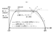
そこで、高速域での減速度低下による走行時分延長を補って定時性を維持するために、駅間走行パターンの調整が必要となる。調整方法には、「巡航速度の増加」「低速域でのブレーキ力増加」の2種類が考えられる。駅間の走行パターンの例を示す図3と図2を用いて、前記2種類の走行パターン調整方法を説明する。 Therefore, it is necessary to adjust the inter-station travel pattern in order to compensate for the extension of travel time due to a decrease in deceleration in the high speed range and to maintain punctuality. There are two types of adjustment methods: “cruising speed increase” and “brake force increase at low speeds”. The two types of travel pattern adjustment methods will be described with reference to FIGS. 3 and 2 showing examples of travel patterns between stations.
基準となる、空気ブレーキ補足を伴う一定のブレーキ力を前提とした走行パターンの例は、図3の記号で「a→b→c→d」と表される。当該走行パターンにおけるブレーキ力特性は、図2の記号「L→D→A」で表される。 An example of a running pattern based on a constant braking force with air brake supplement as a reference is represented by “a → b → c → d” in FIG. The braking force characteristic in the travel pattern is represented by the symbol “L → D → A” in FIG.
全電気ブレーキを使用し、定時性を維持するための調整に「巡航速度の増加」を用いた場合の走行パターンの例は、図3の記号で「a→f→g→d」と表される。当該走行パターンにおけるブレーキ力特性は、図2の記号「K→D→A」で表される。当該走行パターンでは、前記の基準となる走行パターンと比べて、巡航速度が増加している(図3中、第1の巡航速度から第2の巡航速度へ)。すなわち、高速域での減速度低下に伴う走行時分延長を、定速走行区間の走行時間短縮で補っている。 An example of a driving pattern when using all electric brakes and using “increase in cruise speed” for adjustment to maintain punctuality is represented by “a → f → g → d” in FIG. The The braking force characteristic in the traveling pattern is represented by the symbol “K → D → A” in FIG. In the traveling pattern, the cruising speed is increased as compared to the reference traveling pattern (from the first cruising speed to the second cruising speed in FIG. 3). That is, the travel time extension accompanying the decrease in the deceleration in the high speed range is compensated by the reduction of the travel time in the constant speed travel section.
全電気ブレーキ使用下で定時性を維持するための調整に「低速域でのブレーキ力増加」を用いた場合の走行パターンの例は、図3の記号で「a→b→k→d」と表される。当該走行パターンにおけるブレーキ力特性は、図2の記号「K→E→B」で表される。このブレーキ力特性は、モータとして出力可能な全電気ブレーキ力(図2の記号「K→D→E→F→C」)の範囲内で、低速域のブレーキ力を増加させたものである。当該走行パターンでは、前記の基準となる走行パターンと比べて、低速域での減速度が増加することで、低速域の減速を短時間で済ますことができ、高速域での減速度低下に伴う走行時分延長分を補っている。 An example of the driving pattern when “Increase in braking force at low speed” is used for adjustment to maintain punctuality under the use of all electric brakes is “a → b → k → d” as shown in FIG. expressed. The braking force characteristic in the travel pattern is represented by the symbol “K → E → B” in FIG. This braking force characteristic is obtained by increasing the braking force in the low speed range within the range of the total electric braking force that can be output as a motor (symbol “K → D → E → F → C” in FIG. 2). In this driving pattern, the deceleration at the low speed range can be shortened in a short time by increasing the deceleration at the low speed range as compared to the above standard driving pattern, which is accompanied by a decrease in the deceleration at the high speed range. Make up for the extra time.
以上が、前記2種類の走行パターン調整方法の説明である。 The above is the description of the two types of travel pattern adjustment methods.
ブレーキパターンが固定であった、従来の駅間走行パターンの調整においては、巡航速度が主な自由度であった。特許文献2には、巡航速度を主な自由度とする走行パターン調整方法が開示されている。あるいは、巡航速度は変更せず、走行中に残走行時分に応じて、複数のブレーキパターンから適切なものを選択する方法が特許文献3に開示されている。 In the adjustment of the conventional inter-station driving pattern, where the brake pattern was fixed, the cruise speed was the main degree of freedom. Patent Document 2 discloses a traveling pattern adjustment method in which the cruise speed is the main degree of freedom. Alternatively, Patent Document 3 discloses a method for selecting an appropriate one from a plurality of brake patterns according to the remaining travel time during travel without changing the cruise speed.
これらに対し、全電気ブレーキ採用時には、上記の通り、巡航速度とブレーキパターンという2種類の自由度があり、走行パターン調整の演算負荷が大きくなる。車上に搭載する演算装置の性能が、走行パターン調整の演算負荷に対して十分でない場合、走行パターン調整の精度を落とさざるを得ず、全電気ブレーキによる省エネ効果を限定することや、定時性を損なうことにつながる。 On the other hand, when all electric brakes are employed, as described above, there are two kinds of degrees of freedom, that is, the cruise speed and the brake pattern, and the calculation load for running pattern adjustment increases. If the performance of the computing device mounted on the vehicle is not sufficient for the computation load of running pattern adjustment, the accuracy of running pattern adjustment must be reduced, limiting the energy saving effect of all electric brakes, and punctuality Will lead to damage.
上記課題を解決するために、例えば特許請求の範囲に記載の構成を採用する。 In order to solve the above problems, for example, the configuration described in the claims is adopted.
本願は上記課題を解決する手段を複数含んでいるが、その一例を挙げるならば、「少なくとも自列車の応荷重情報を基に自列車の全電気ブレーキによる最大ブレーキ力特性を設定する最大ブレーキ力特性設定手段と、前記最大ブレーキ力特性、及び、次駅の目標到着時刻の各情報に基づいて、全電気ブレーキによる最大ブレーキ力を利用して当該目標到着時刻以前に次駅に停車するための前記次駅までの巡航速度を設定する巡航速度設定手段とを備え、前記巡航速度の情報に基づいて、前記次駅までの駅間におけるブレーキパターンを決定するブレーキパターン決定手段を備え、前記巡航速度及び前記ブレーキパターンに基づいて列車の走行速度を自動制御すること、を特徴とする自動列車運転装置」又は「少なくとも自列車の応荷重情報を基に自列車の全電気ブレーキによる最大ブレーキ力特性を設定する最大ブレーキ力特性設定手段と、前記最大ブレーキ力特性、及び、次駅の目標到着時刻の各情報に基づいて、全電気ブレーキによる最大ブレーキ力を利用して当該目標到着時刻以前に次駅に停車するための前記次駅までの巡航速度を設定する巡航速度設定手段と、前記巡航速度の情報に基づいて、前記次駅までの駅間におけるブレーキパターンを決定するブレーキパターン決定手段と、前記巡航速度と前記ブレーキパターンによる前記次駅までの走行パターンを実現するための運転操作を前記運転士に教示する運転操作教示手段とを備えることを特徴とする列車運転支援装置。」である。
The present application includes a plurality of means for solving the above-mentioned problems. For example, the maximum braking force that sets the maximum braking force characteristic by all the electric brakes of the own train based on at least the load information of the own train. For stopping at the next station before the target arrival time using the maximum braking force by all electric brakes based on the characteristic setting means, the maximum brake force characteristic, and the target arrival time information of the next station A cruise speed setting means for setting a cruise speed to the next station, and a brake pattern determination means for determining a brake pattern between stations to the next station based on the information on the cruise speed, the cruise speed And an automatic train driving device characterized by automatically controlling the traveling speed of the train based on the brake pattern "or" at least the load information of the own train. The maximum braking force characteristic setting means for setting the maximum braking force characteristic by all electric brakes of the own train, the maximum braking force characteristic setting means, and the maximum braking force by all electric brakes based on each information of the maximum braking force characteristic and the target arrival time of the next station Between the station to the next station based on the cruise speed setting means for setting the cruise speed to the next station to stop at the next station before the target arrival time using force, and the information on the cruise speed It is obtained Bei brake pattern determining means for determining a brake pattern and driving operation teaching means for teaching the operator's driving operation for realizing a running pattern to the next station by the brake pattern and the cruising speed at A train operation support device characterized by the above. "
全電気ブレーキによる省エネ効果と定時性を両立できる走行パターンを、低い演算負荷で作成することが可能になる。 It is possible to create a traveling pattern that can achieve both energy saving effect and punctuality by all electric brakes with low computational load.
図1〜10を用いて、各実施形態を詳細に説明する。 Each embodiment will be described in detail with reference to FIGS.
本実施例では、出力可能な最大全電気ブレーキ力特性に基づいて、発車前に駅間の巡航速度を設定し、その後、停止制御開始までの間に、当該設定された巡航速度に基づいて、ブレーキパターンを決定する自動列車運転装置の例を説明する。 In this example, based on the maximum total electric brake force characteristics that can be output, set the cruise speed between stations before departure, and then, based on the set cruise speed before the start of stop control, An example of an automatic train driving device that determines a brake pattern will be described.
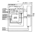
まず、図1を参照して、本発明の自動列車運転装置101の構成について説明する。自動列車運転装置101は、駅間の走行パターンを計画する走行パターン計画手段102と、前記走行パターン計画手段102で計画された走行パターンに従って列車を走行させるための制御指令を算出する制御指令算出手段103と、で構成される。走行パターンの一例として、位置に応じた目標走行速度が挙げられる。図1に示すように本実施例では前記自動列車運転装置101を車上に搭載する例を示すが、前記走行パターン計画手段102を地上に、前記制御指令算出手段103を車上に分散させて配置することも可能である。 First, with reference to FIG. 1, the structure of the automatic train operation apparatus 101 of this invention is demonstrated. The automatic train driving device 101 includes a travel pattern planning unit 102 that plans a travel pattern between stations, and a control command calculation unit that calculates a control command for causing the train to travel according to the travel pattern planned by the travel pattern planning unit 102. 103. An example of the travel pattern is a target travel speed according to the position. As shown in FIG. 1, this embodiment shows an example in which the automatic train driving device 101 is mounted on the vehicle. However, the traveling pattern planning means 102 is distributed on the ground, and the control command calculating means 103 is distributed on the vehicle. It is also possible to arrange.
前記走行パターン計画手段102は、最大全電気ブレーキ力特性設定手段104と、巡航速度設定手段105と、ブレーキパターン決定手段106とから構成される。
The travel pattern planning unit 102 includes a maximum total electric brake force
前記最大全電気ブレーキ力特性設定手段104は、応荷重情報、天候情報、および列車駆動用の駆動装置の主回路の故障情報を入力とし、当該列車で現在出力できる最大の全電気ブレーキ力特性を設定する。本設定方法は後述する。前記最大全電気ブレーキ力特性設定手段104から出力されたブレーキ力特性は、前記巡航速度設定手段105と前記ブレーキパターン決定手段106とに入力される。
The maximum total electric brake force characteristic setting means 104 receives the load information, the weather information, and the failure information of the main circuit of the driving device for driving the train. Set. This setting method will be described later. The braking force characteristic output from the maximum total electric braking force
前記巡航速度設定手段105は、自列車の現在駅の予定発車時刻と、自列車の次駅への目標到着時刻と、次駅までの駅間路線条件と自列車の車両条件と、前記最大全電気ブレーキ力特性設定手段104の出力である最大全電気ブレーキ力特性と、を入力とし、次駅までの走行パターンにおける巡航速度を設定する。本設定方法は後述する。ここで前記駅間路線条件には、少なくとも駅間距離と、路線勾配と、曲線情報と、制限速度情報のいずれかが含まれる。また、前記車両条件には、少なくとも、車両の加速特性が含まれる。また、前記巡航速度は、定速運転時の目標速度、あるいは、惰行と再力行を行って走行する区間の平均速度を規定する。前記巡航速度設定手段105から出力された巡航速度は、前記制御指令算出手段103と前記ブレーキパターン決定手段106とに入力される。 The cruise speed setting means 105 includes a scheduled departure time at the current station of the own train, a target arrival time at the next station of the own train, an inter-station route condition to the next station, a vehicle condition of the own train, and the maximum all The maximum total electric brake force characteristic that is the output of the electric brake force characteristic setting means 104 is used as an input, and the cruise speed in the travel pattern to the next station is set. This setting method will be described later. Here, the inter-station route condition includes at least one of a distance between stations, a route gradient, curve information, and speed limit information. The vehicle condition includes at least acceleration characteristics of the vehicle. The cruise speed defines a target speed at a constant speed operation or an average speed of a section in which coasting and repowering are performed. The cruising speed output from the cruising speed setting means 105 is input to the control command calculation means 103 and the brake pattern determination means 106.
前記ブレーキパターン決定手段106は、前記最大全電気ブレーキ力特性と、前記巡航速度と、前記目標到着時刻と、前記駅間路線条件と、前記車両条件と、を入力とし、次駅までの駅間走行の停止制御におけるブレーキパターンを決定する。本決定方法は後述する。ここでブレーキパターンは、位置に応じた目標速度として表現する方法が考えられる。前記ブレーキパターン決定手段106から出力されたブレーキパターンは、前記制御指令算出手段103に入力される。
The brake pattern determining means 106 receives the maximum total electric brake force characteristic, the cruise speed, the target arrival time, the inter-station route condition, and the vehicle condition, and inputs the distance between stations to the next station. The brake pattern in the travel stop control is determined. This determination method will be described later. Here, a method of expressing the brake pattern as a target speed corresponding to the position can be considered. The brake pattern output from the brake
前記制御指令算出手段103は、前記巡航速度設定手段105から取得する巡航速度を加速および定速走行の目標速度(あるいは、惰行再力行走行における目標平均速度)とし、また、前記ブレーキパターン決定手段106から取得するブレーキパターンを停止制御時の目標速度とする。そして、前記自動列車運転装置101の外部から取得する自列車の車両速度と車両位置を入力として、これらの目標速度に沿った運転がなされるように、制駆動制御装置へ制御指令を出力する。 The control command calculation means 103 sets the cruising speed acquired from the cruising speed setting means 105 as a target speed for acceleration and constant speed running (or a target average speed for coasting repowering running), and the brake pattern determining means 106 The brake pattern acquired from is used as the target speed for stop control. Then, using the vehicle speed and the vehicle position of the own train acquired from the outside of the automatic train driving apparatus 101 as inputs, a control command is output to the braking / driving control apparatus so that the operation along these target speeds is performed.
以上が自動列車運転装置101の構成の説明である。 The above is the description of the configuration of the automatic train driving apparatus 101.
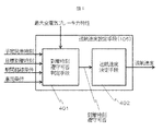
次に、図4を参照して、前記巡航速度設定手段105の内部構成を説明する。前記巡航速度設定手段105は、到達時刻遵守可否判定手段401と巡航速度決定手段402とから構成される。 Next, the internal configuration of the cruise speed setting means 105 will be described with reference to FIG. The cruise speed setting means 105 is composed of arrival time compliance determination means 401 and cruise speed determination means 402.
前記到着時刻遵守可否判定手段401は、前記予定発車時刻と、前記目標到着時刻と、前記駅間路線条件と、前記車両条件と、を入力として、自列車が次駅に前記目標到着時刻までに到着できるか否かを判定する。前記巡航速度決定手段402は、前記判定の結果に基づいて、前記巡航速度設定手段105として設定する巡航速度を決定する。前記到着時刻遵守可否判定手段401と前記巡航速度決定手段402における処理の詳細は後述する。
The arrival time
以上が、前記巡航速度設定手段105の内部構成の説明である。 The above is the description of the internal configuration of the cruise speed setting means 105.
次に、図5のフローチャートを参照して、前記走行パターン計画手段102の内部で行われる処理を説明する。ステップ501では、自列車が駅に停止しているか否かを判定し、駅に停止している場合はステップ502へ進む。未停止の場合は処理を終える。
Next, with reference to the flowchart of FIG. 5, the process performed inside the said travel pattern plan means 102 is demonstrated. In
ステップ502では、前記最大全電気ブレーキ力特性設定手段104が、自列車の応荷重情報、天候情報、および、駆動装置の故障情報を取得する。応荷重は車両毎に空気ばねの圧力から算出された値である。天候情報は例えば列車外部から無線通信等で取得する方法があり、少なくとも降雨や降雪の有無に関する情報が含まれる。駆動装置の故障情報は例えば車両情報制御装置から取得する方法がある。
In
ステップ503では、前記最大全電気ブレーキ力特性設定手段104が、ステップ502で取得した情報を用いて、自列車の最大全電気ブレーキ力特性を設定する。ここでブレーキ力特性は、図2の記号「K→D→E→F→C」で例示されるように、速度に応じたブレーキ力として表される。列車全体での最大全電気ブレーキ力特性は、各動力台車に搭載されたモータの最大全電気ブレーキ力特性の和である。ステップ502で取得した駆動装置の故障情報で、故障と判定されている駆動装置が駆動するモータがある場合、当該モータの分だけ、列車全体での最大全電気ブレーキ力特性が小さくなる。
In
各モータの最大全電気ブレーキ力特性は、低速域のブレーキ力が一定の部分(図2の記号「C→F」)と、速度増加に伴ってブレーキ力が減少する部分(図2の記号「F→E→D→K」)に分けられる。前者の一定ブレーキ力の値は、予め設計値として定められた設計最大ブレーキ力以下の範囲で、ステップ502で取得した応荷重情報および天候情報によって決定される。
The maximum total electric braking force characteristics of each motor include a portion where the braking force in the low speed range is constant (symbol “C → F” in FIG. 2) and a portion where the braking force decreases as the speed increases (the symbol “ F → E → D → K ”). The value of the former constant braking force is determined by the applied load information and the weather information acquired in
具体的には、応荷重情報から計算される軸重に、天候情報から決まる粘着係数を乗じることで、各動力台車が滑走を発生させずに出力し得る最大ブレーキ力を推定計算し、当該推定値と前記設計最大ブレーキ力との大小関係で小さい方が、前記の一定ブレーキ力の値として採用される。ここで粘着係数は、降雨あるいは降雪の天候情報がある場合は、そうでない場合と比較して小さく設定される。 Specifically, by multiplying the axle weight calculated from the applied load information by the adhesion coefficient determined from the weather information, the maximum braking force that each power bogie can output without causing sliding is estimated and calculated. The smaller value in the magnitude relationship between the value and the designed maximum braking force is adopted as the value of the constant braking force. Here, the adhesion coefficient is set smaller when there is rainy or snowy weather information than when it is not.
ステップ504では、前記巡航速度設定手段105に含まれる前記到着時刻遵守可否判定手段401が、前記目標到着時刻と、前記駅間路線条件と、前記車両条件と、を取得する。
In
ステップ505では、前記到着時刻遵守可否判定手段401において、所定の第一の巡航速度と前記の最大全電気ブレーキ力特性とに従って次駅間を走行した場合に、自列車が次駅の目標到着時刻を遵守できるか否かを判定する。当該判定の方法は後述する。前記第一の巡航速度は、各駅間について、駅間の制限速度から下方に一定の余裕(例えば5km/h)を持たせた速度に設定することが考えられる。
In
ステップ506では、ステップ505の判定結果に基づき、前記巡航速度決定手段402において、遵守可の場合はステップ507aへ遷移し、遵守不可の場合はステップ507bへ遷移する。
In
ステップ507aでは、前記巡航速度決定手段402において、次駅間の巡航速度として前記第一の巡航速度を設定する。ステップ507bでは、前記巡航速度決定手段402において、次駅間の巡航速度として、前記第一の巡航速度よりも高い第二の巡航速度を設定する。前記第二の巡航速度は、各駅間について、制限速度の範囲内で、前記第一の巡航速度よりも所定幅(例えば2km/h)高い速度に設定することが考えられる。
In step 507a, the cruise speed determination means 402 sets the first cruise speed as the cruise speed between the next stations. In
なお、前記第一の巡航速度、および前記第二の巡航速度とは、定速運転を実施する場合には定速運転の目標速度であり、惰行と再力行を使用する運転方法においては、
当該運転方法で走行する区間における平均速度に対応する。
The first cruising speed and the second cruising speed are the target speeds of constant speed operation when carrying out constant speed operation, and in the driving method using coasting and repowering,
It corresponds to the average speed in the section traveling with the driving method.
ステップ508では、前記巡航速度設定手段105から前記制御指令算出手段103に対し、駅間の巡航速度が伝達され、発車準備完了となる。
In
ステップ509では、前記ブレーキパターン決定手段106において、前記巡航速度設定手段105で設定された巡航速度で走行すると仮定した場合に、次駅への目標到着時刻を遵守可能なブレーキパターンを決定する。ここで決定されるブレーキパターンは、前記最大全電気ブレーキ力特性設定手段104で設定されたブレーキ力特性以下の範囲内で設定されることが望ましいが、発車後に次駅の目標到着時刻が前倒しされた場合のように、より強いブレーキ力が必要な場合には、空気ブレーキの補足を伴うブレーキパターンに設定されることも有り得る。残走行時分に応じて、複数のブレーキパターンから適切なものを選択する方法は、例えば特許文献3に開示されている方法を用いることができる。
In
ここで、目標到着時刻を遵守するブレーキパターンの生成が、自列車の停止制御開始タイミングに間に合わない恐れがあることを判定する仕組みを設け、間に合わないと判定された場合に、既定の固定ブレーキパターンを使用して駅への停止制御を行うよう、バックアップの仕組みを設けておいても良い。こうすることで、ブレーキパターンの生成が遅れた場合でも、確実に停止制御を開始できるという効果がある。前記判定基準の例として、駅間の中間地点で前記ブレーキパターン決定手段106によるブレーキパターン生成が終わっているか否かを判定基準とすることが考えられる。 Here, a mechanism for determining that there is a possibility that the generation of the brake pattern that observes the target arrival time may not be in time for the stop control start timing of the own train is provided. A backup mechanism may be provided so that the stop control to the station is performed using. By doing so, there is an effect that the stop control can be surely started even when the generation of the brake pattern is delayed. As an example of the determination criterion, it can be considered that the determination criterion is whether or not the brake pattern generation by the brake pattern determination means 106 is finished at an intermediate point between stations.
以上が、前記走行パターン計画手段102の内部で行われる処理の説明である。 The above is the description of the processing performed inside the travel pattern planning unit 102.
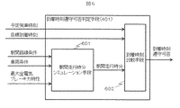
次に、図6を参照して、前記到着時刻遵守可否判定手段401の構成要素、および前記ステップ505の処理内容詳細を説明する。前記到着時刻遵守可否判定手段401は、駅間走行時分シミュレーション手段601と到着時刻比較手段602とから構成される。
Next, with reference to FIG. 6, the constituent elements of the arrival time
前記駅間走行時分シミュレーション手段601は、前記駅間路線条件と、前記車両条件と、前記最大全電気ブレーキ力特性と、を入力として数値シミュレーションにより駅間走行時分を出力する。この数値シミュレーションにおいては、前記第一の巡航速度を前提とする。したがって、駅間の走行パターンは、前記車両条件と前記駅間路線条件で決まる加速パターンと、前記第一の巡航速度による定速走行パターンもしくは惰行再力行による走行パターンと、前記最大全電気ブレーキ力特性と前記駅間路線条件で決まる減速パターンとの組み合わせとなる。 The inter-station travel time simulation means 601 outputs the inter-station travel time by numerical simulation with the inter-station route condition, the vehicle condition, and the maximum total electric brake force characteristic as inputs. In this numerical simulation, the first cruise speed is assumed. Therefore, the traveling pattern between stations includes an acceleration pattern determined by the vehicle condition and the inter-station route condition, a constant speed traveling pattern by the first cruise speed or a traveling pattern by coasting repowering, and the maximum total electric braking force. This is a combination of characteristics and a deceleration pattern determined by the inter-station route conditions.
前記到着時刻比較手段602は、前記予定発車時刻と、前記目標到着時刻と、前記駅間走行シミュレーション手段601から取得する駅間走行時分と、を入力とし、自列車の次駅における到着時刻遵守可否を出力する。前記到着時刻比較手段602内部では、前記予定発車時刻に前記駅間走行時分を加えた時刻である予定到着時刻と前記目標到着時刻とを比較し、前記目標到着時刻よりも前記予定到着時刻が早いか(同時刻も含む)、あるいは、前記目標到着時刻に対する前記予定到着時刻の遅れが所定範囲内であれば、到着時刻遵守可の判定結果を出力する。それ以外の場合は到着時刻遵守不可の判定結果を出力する。 The arrival time comparison means 602 receives the scheduled departure time, the target arrival time, and the inter-station travel time obtained from the inter-station travel simulation means 601 as input, and adheres to the arrival time at the next station of the own train. Outputs availability. Inside the arrival time comparison means 602, the planned arrival time, which is a time obtained by adding the travel time between stations to the planned departure time, is compared with the target arrival time, and the planned arrival time is more than the target arrival time. If it is early (including the same time) or if the delay of the scheduled arrival time with respect to the target arrival time is within a predetermined range, a determination result indicating that the arrival time can be observed is output. In other cases, a determination result indicating that the arrival time cannot be observed is output.
ここで前記所定範囲は、運用上の都合や利用客の利便性を考慮して定められる。運用上の都合に関しては、自列車の次駅到着遅れが後続列車のダイヤ乱れに波及しないようにする必要がある。したがって、ダイヤが稠密な路線では、前記所定範囲は小さく設定される。利用客の利便性に関しては、自列車の次駅到着遅れが、次駅での他列車への乗換えに支障することとないようにする必要がある。したがって、次駅での他列車への乗換え時間に余裕がない場合には、前記所定範囲は小さく設定される。 Here, the predetermined range is determined in consideration of operational convenience and user convenience. Regarding operational convenience, it is necessary to prevent the arrival delay of the next station of the own train from affecting the timetable disturbance of the following train. Therefore, the predetermined range is set to be small on a route with dense diamonds. Regarding the convenience of passengers, it is necessary that the arrival delay of the next station of the own train does not hinder the transfer to another train at the next station. Therefore, when there is no allowance for transfer time to another train at the next station, the predetermined range is set small.
以上が、前記到着時刻遵守可否判定手段401の説明である。
The above is the description of the arrival time
最後に、本発明によって、全電気ブレーキによる省エネ効果と定時性を両立できる走行パターンが、少ない演算負荷で作成可能となる仕組みを説明する。まず、本発明では、駅間走行パターンの計画にあたり、巡航速度を先に決定し、その後にブレーキパターンを決定する。これは、巡航速度は発車後、加速する際の目標速度であるため、発車前に優先して決定する必要があるのに対し、ブレーキパターンの決定は、自列車が発車して巡航速度に到達した後、このブレーキパターンに基づく停止制御を開始するタイミングまでに実施されればよい、という原理に基づく。 Finally, a description will be given of a mechanism by which a traveling pattern that can achieve both energy saving effect and punctuality by all electric brakes can be created with a small calculation load according to the present invention. First, in the present invention, when planning a traveling pattern between stations, the cruise speed is determined first, and then the brake pattern is determined. This is because the cruise speed is the target speed when accelerating after departure, so it is necessary to prioritize it before departure, whereas the brake pattern is determined by the train leaving the cruise speed. After that, it is based on the principle that it may be carried out by the timing of starting stop control based on this brake pattern.
本発明によれば、巡航速度を先に決定して制御指令算出手段に出力し、その後にブレーキパターンを決定して制御指令算出手段に出力する構成としたため、発車前に駅間の走行パターンを全て演算し終える必要は無く、巡航速度決定の演算処理は発車前に実施し、ブレーキパターン決定の演算処理は発車した後、遅くとも停止制御前までに完了させれば良い。したがって、走行パターンの演算処理を時間的に分散させられるため、発車前に駅間走行パターンを全て決定する方法と比較して、発車前の演算負荷の低減が可能になる。発車前の演算負荷の低減は、必要となる車上の演算装置の性能を抑えることによる低コスト化や、空いたリソースを活かした他機能の演算を可能にすることによる車上装置の高付加価値化に貢献する。 According to the present invention, the cruise speed is determined first and output to the control command calculation means, and then the brake pattern is determined and output to the control command calculation means. It is not necessary to finish all the calculations, and the calculation process for determining the cruising speed may be performed before departure, and the calculation process for determining the brake pattern may be completed after the departure and before the stop control at the latest. Therefore, since the calculation processing of the travel pattern can be dispersed in time, it is possible to reduce the calculation load before departure as compared with the method of determining all the inter-station travel patterns before departure. Reducing the computation load before departure reduces costs by reducing the performance of necessary on-vehicle computing devices, and adds high on-vehicle devices by enabling computation of other functions that take advantage of available resources. Contribute to value.
本発明は、走行パターンの演算処理を時間的に分散させる方法の中でも、発車前に行う巡航速度決定の演算において、最大全電気ブレーキ力特性を考慮している点が特徴である。走行パターンの演算処理を時間的に分散させる他の方法として、ブレーキパターンの限界とは無関係に巡航速度を決定し、走行しながらブレーキパターンを決定する方法も考えられるが、この方法では、定時性や省エネ性に課題がある。 The present invention is characterized in that the maximum total electric brake force characteristic is taken into consideration in the cruise speed determination calculation performed before departure, among the methods for temporally distributing the calculation processing of the running pattern. As another method for temporally distributing the calculation processing of the driving pattern, a method of determining the cruising speed regardless of the limit of the brake pattern and determining the brake pattern while driving can be considered. And there is a problem in energy saving.
すなわち、強い全電気ブレーキが使用できないのにも関わらず、高い巡航速度を設定した場合、定時性を遵守するために空気ブレーキ補足を伴うブレーキを使用することとなり、エネルギ損失が増加する。あるいは、空気ブレーキ補足をしないことを優先すると、早いタイミングでのブレーキ開始が必要となり、定時性が損なわれる。逆に強い全電気ブレーキが使用できるのにも関わらず、低い巡航速度を設定した場合、停止制御自体は全電気ブレーキの範囲で実施できるものの、巡航速度を不必要に低く設定しているため、定時性が損なわれる。 That is, even if a strong all-electric brake cannot be used, if a high cruise speed is set, a brake with an air brake supplement is used in order to comply with punctuality, resulting in an increase in energy loss. Alternatively, if priority is given to not supplementing the air brake, it is necessary to start the brake at an early timing, which impairs the punctuality. On the other hand, even if a strong all-electric brake can be used, if a low cruising speed is set, the stop control itself can be performed in the range of all the electric brakes, but the cruising speed is set unnecessarily low. Timeliness is impaired.
本発明では、発車前に行う巡航速度決定の演算において、最大全電気ブレーキ力特性を考慮しているため、定時性を維持しつつ、省エネ性を損なわない、適切な巡航速度の設定が可能となる。以上が、本発明によって、演算負荷を低減しつつ省エネと定時性を向上できる仕組みの説明である。 In the present invention, since the maximum total electric brake force characteristic is considered in the calculation of the cruise speed determination performed before departure, it is possible to set an appropriate cruise speed without impairing energy saving performance while maintaining punctuality. Become. The above is the description of the mechanism by which the present invention can improve the energy saving and punctuality while reducing the calculation load.
以上が実施例1の説明である。 The above is the description of the first embodiment.
本実施例では、出力可能な最大全電気ブレーキ力特性に基づいて決定された駅間の巡航速度に関する情報を、発車前に運転士に教示し、その後、停止制御開始までの間に、当該巡航速度に基づいて決定されたブレーキパターンに関する情報を運転士に教示する列車運転支援装置の例を説明する。本実施例の列車運転支援装置によれば、運転士が列車を運転する路線において、全電気ブレーキを活用しつつ、省エネ性や定時性に優れた手動運転が可能である。 In this embodiment, information on the cruise speed between stations determined based on the maximum total electric brake force characteristic that can be output is taught to the driver before departure, and then the cruise is performed before the stop control starts. An example of a train operation support device that teaches the driver information regarding the brake pattern determined based on the speed will be described. According to the train operation support device of the present embodiment, manual operation excellent in energy saving and on-time performance is possible on a route on which a driver operates a train while utilizing all electric brakes.
まず、図7を参照して、列車運転支援装置701の構成について説明する。 First, the configuration of the train operation support apparatus 701 will be described with reference to FIG.
前記列車運転支援装置701は、駅間の走行パターンを計画する走行パターン計画手段102と、前記走行パターン計画手段102で計画された走行パターンに従って列車を走行させるための運転操作に関して、運転士への教示内容を作成する教示内容作成手段703と、で構成される。前記走行パターン計画手段102は、実施例1と同一であるため、構成およびその内部処理の説明は省略する。 The train operation support device 701 provides a driving pattern planning unit 102 that plans a traveling pattern between stations and a driving operation for causing a train to travel according to the traveling pattern planned by the traveling pattern planning unit 102. And teaching content creating means 703 for creating teaching content. Since the travel pattern planning unit 102 is the same as that of the first embodiment, the description of the configuration and the internal processing is omitted.
前記教示内容作成手段703は、前記巡航速度設定手段105から取得する巡航速度を加速および定速走行の目標速度とし、また、前記ブレーキパターン決定手段106から取得するブレーキパターンを停止制御時の目標速度とする。そして、前記列車運転支援装置701の外部から取得する自列車の車両速度と車両位置を入力として、これらの目標速度に沿った運転がなされるように、運転操作の教示内容を作成する。教示内容は、運転操作の内容が表示された画面や、適当なタイミングで出力される音声によって運転士に伝達される。前記教示内容作成手段703は液晶モニタやスピーカなどの出力装置を備えて構成される。 The teaching content creating means 703 sets the cruising speed acquired from the cruising speed setting means 105 as the target speed for acceleration and constant speed running, and the brake pattern acquired from the brake pattern determining means 106 as the target speed for stop control. And Then, using the train speed and position of the host train acquired from the outside of the train operation support apparatus 701 as input, the teaching content of the driving operation is created so that the operation along these target speeds is performed. The teaching content is transmitted to the driver by a screen on which the content of the driving operation is displayed or by sound output at an appropriate timing. The teaching content creating means 703 includes an output device such as a liquid crystal monitor and a speaker.
以上が列車運転支援装置701の構成の説明である。 The above is the description of the configuration of the train operation support device 701.
次に、前記教示内容作成手段703で作成される教示内容の具体例を図8、図9、図10を参照して説明する。 Next, specific examples of the teaching contents created by the teaching contents creating means 703 will be described with reference to FIGS.
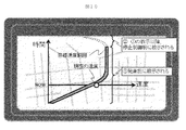
図8は、運転操作を教示する画面表示の一形態であり、画面上には次駅までの駅間走行パターンの描画と運転操作のポイント表示がある。駅間走行パターンは、発駅からの加速と、所定速度での定速走行と、次駅に向けた減速と、から成る。走行パターンの表示には、自列車の現在位置と速度を表すマークが重ね合わせて描画される。運転操作のポイント表示は、加速と定速に関しては目標速度が、減速に関しては制動開始位置やノッチ操作が教示される。運転操作を教示する画面表示の本形態によれば、駅間走行全体のイメージを予め把握して運転操作を行うことができる。 FIG. 8 shows one form of a screen display that teaches a driving operation. On the screen, there is a drawing of an inter-station traveling pattern up to the next station and a point display of the driving operation. The inter-station travel pattern includes acceleration from the departure station, constant speed travel at a predetermined speed, and deceleration toward the next station. In the display of the running pattern, marks representing the current position and speed of the own train are drawn in an overlapping manner. The driving operation point display teaches the target speed for acceleration and constant speed, and the braking start position and notch operation for deceleration. According to this form of the screen display that teaches the driving operation, the driving operation can be performed by grasping in advance the image of the entire traveling between stations.
本実施例の列車運転支援装置における図8の画面表示の特徴として、加速と定速の目標速度に関する内容は発車前に教示され、減速に関する内容は、加速と定速の目標速度に関する教示より後のタイミングで教示される。画面上に描かれる走行パターンを表す線についても、加速と定速の部分が先に描画され、減速の部分は後から描画される。 As a feature of the screen display of FIG. 8 in the train operation support device of this embodiment, the contents relating to the acceleration and constant speed target speed are taught before departure, and the contents relating to deceleration are after the instruction relating to the acceleration and constant speed target speed. Is taught at the timing. As for the line representing the running pattern drawn on the screen, the acceleration and constant speed portions are drawn first, and the deceleration portion is drawn later.
減速に関する教示方法の別の方法としては、ブレーキパターンの決定前は、おおよその減速開始位置やブレーキパターン表示(色を薄くするなど)に留め、ブレーキパターン決定後に正確な情報を教示する方法も考えられる。この方法であれば、運転士が駅間走行の全体感を予め把握し易くなる。なお、教示方法は図8に示すような画面上の表示に限らず、音声による伝達手段が伴っていても良い。音声による伝達手段が伴うことで、運転士の前方注視への影響を小さくすることができる。 Another method for teaching about deceleration is to keep the approximate deceleration start position and brake pattern display (such as lighter color) before determining the brake pattern, and to teach accurate information after determining the brake pattern. It is done. With this method, the driver can easily grasp the overall feeling of traveling between stations in advance. The teaching method is not limited to the display on the screen as shown in FIG. 8, but may be accompanied by a voice transmission means. The accompanying voice transmission means can reduce the influence on the driver's forward gaze.
図9は、運転操作を教示する画面表示の別形態であり、現在速度表示領域(図9左側)と、運転操作教示領域(図9右側)とから構成される。そして現在速度表示領域には、自列車の現在の速度を指した円形状の速度メータが表示される。また速度メータの周囲には環状の目標速度範囲表示部が表示され、この目標速度範囲表示部のうち、そのとき自列車が目標とすべき速度範囲と対応する箇所が所定色で強調表示される。 FIG. 9 shows another form of screen display for teaching a driving operation, which is composed of a current speed display area (left side in FIG. 9) and a driving operation teaching area (right side in FIG. 9). In the current speed display area, a circular speed meter indicating the current speed of the own train is displayed. An annular target speed range display section is displayed around the speedometer, and a portion of the target speed range display section that corresponds to the speed range that the train should target at that time is highlighted in a predetermined color. .
また運転操作教示領域には、前記走行パターン計画手段102が計画した走行パターンで自列車を走行させるために、運転士が行うべき運転操作の操作内容が表示される。例えば図9の例では、まず「80km/hまで加速」し、その後「80km/hの速度を維持」した後、「23.10km地点から減速」すべきことが示されている。そして、これら操作内容のうち、現在、運転士が行うべき運転操作の操作内容を表示した部分が所定色で強調表示される。 In the driving operation teaching area, the operation content of the driving operation to be performed by the driver is displayed in order to cause the train to travel in the traveling pattern planned by the traveling pattern planning unit 102. For example, in the example of FIG. 9, it is shown that “accelerate to 80 km / h”, “maintain the speed of 80 km / h”, and then “decelerate from the 23.10 km point”. Of these operation contents, the part displaying the operation contents of the driving operation to be performed by the driver is highlighted with a predetermined color.
運転操作を教示する画面表示の本形態では、運転士は、現在速度表示領域に表示された速度メータを参照しながら、運転操作教示領域に表示された各操作内容に従って運転操作を行うことによって、前記走行パターン計画手段102が作成した速度パターンに追従するよう自列車を走行させることができる。 In this form of the screen display that teaches the driving operation, the driver performs the driving operation according to each operation content displayed in the driving operation teaching area while referring to the speed meter displayed in the current speed display area, The own train can be made to follow the speed pattern created by the travel pattern planning means 102.
本実施例の列車運転支援装置における図9の画面表示の特徴として、加速と速度維持に関する内容は発車前に教示されているのに対し、減速に関する内容は、加速と速度維持に関する教示より後のタイミングで教示される。減速に関する教示方法の別の方法としては、ブレーキパターンの決定前は、おおよその減速開始位置の教示に留め、ブレーキパターン決定後に、より明確な情報を教示する方法も考えられる。この方法であれば、運転士が駅間走行の全体感を予め把握し易くなる。なお、教示方法は図9に示すような画面上の表示に限らず、音声による伝達手段が伴っていても良い。音声による伝達手段が伴うことで、運転士の前方注視への影響を小さくすることができる。 As a feature of the screen display of FIG. 9 in the train operation support device of the present embodiment, the contents relating to acceleration and speed maintenance are taught before departure, whereas the contents relating to deceleration are after the instruction relating to acceleration and speed maintenance. Teach with timing. As another method for teaching about deceleration, it is conceivable that only the approximate deceleration start position is taught before the brake pattern is determined, and clearer information is taught after the brake pattern is determined. With this method, the driver can easily grasp the overall feeling of traveling between stations in advance. The teaching method is not limited to the display on the screen as shown in FIG. 9, but may be accompanied by a voice transmission means. The accompanying voice transmission means can reduce the influence on the driver's forward gaze.
図10は、運転操作を教示する画面表示の別形態であり、自列車が目標とすべき速度(以下、これを目標速度と呼ぶ)の範囲に現在の自列車の速度を重ねて表示することにより、速度のコントロールを運転士に促す場合の画面表示例である。 FIG. 10 is another form of screen display that teaches the driving operation, and displays the current speed of the own train in a range of the speed that the own train should target (hereinafter referred to as the target speed). This is a screen display example when prompting the driver to control the speed.
この画面表示では、画面の縦方向と平行に時間軸が表示され、画面の横方向と平行に速度を表す速度軸が表示される。この速度軸は、自列車が前の停車駅を出発してからの経過時間に応じて画面の下側から上側に移動してゆくように表示される。またこの速度軸上のそのときの自列車の速度に応じた位置には、これを表すマークが表示される。 In this screen display, a time axis is displayed in parallel with the vertical direction of the screen, and a speed axis representing speed is displayed in parallel with the horizontal direction of the screen. This speed axis is displayed so as to move from the lower side of the screen to the upper side according to the elapsed time since the own train departed from the previous stop station. In addition, a mark representing this is displayed at a position corresponding to the speed of the current train on the speed axis.
さらにこの画面表示には、前記走行パターン計画手段102が作成した速度パターンに従って走行するために、自列車が目標とすべき経過時間ごとの速度範囲を表す帯状の模様が表示される。 Further, in this screen display, a belt-like pattern representing the speed range for each elapsed time that the train should aim for in order to travel according to the speed pattern created by the travel pattern planning means 102 is displayed.
従って、運転操作を教示する画面表示の本形態では、運転士は、自列車の速度を表すマークが目標速度の範囲を表す模様内に位置するように自列車の速度をコントロールすることによって、前記走行パターン計画手段102が作成した速度パターンに追従するよう自列車を走行させることができる。 Therefore, in this form of the screen display that teaches the driving operation, the driver controls the speed of the own train so that the mark representing the speed of the own train is positioned within the pattern representing the range of the target speed. The own train can be made to follow the speed pattern created by the travel pattern planning means 102.
本実施例の列車運転支援装置における図10の画面表示の特徴として、加速区間と定速走行区間の目標速度範囲が発車前に表示されているのに対し、減速区間の目標速度範囲は加速区間と定速区間の表示よりも後のタイミングで表示される。減速区間に関する別の表示方法としては、ブレーキパターンの決定前は、目標速度範囲を示す領域の色を薄くするなど、おおよその目標速度範囲表示に留め、ブレーキパターン決定後に色をはっきりさせるなどして、明確な情報を表示する方法も考えられる。この方法であれば、運転士が駅間走行の全体感を予め把握し易くなる。なお、教示方法は図9に示すような画面上の表示に限らず、音声による伝達手段が伴っていても良い。音声による伝達手段が伴うことで、運転士の前方注視への影響を小さくすることができる。 As a feature of the screen display of FIG. 10 in the train operation support device of the present embodiment, the target speed range of the acceleration section and the constant speed traveling section is displayed before departure, whereas the target speed range of the deceleration section is the acceleration section. And at a later timing than the constant speed section. Another way to display the deceleration zone is to keep the approximate target speed range display, such as dimming the color of the area indicating the target speed range before the brake pattern is determined, and clarify the color after determining the brake pattern. A method of displaying clear information is also conceivable. With this method, the driver can easily grasp the overall feeling of traveling between stations in advance. The teaching method is not limited to the display on the screen as shown in FIG. 9, but may be accompanied by a voice transmission means. The accompanying voice transmission means can reduce the influence on the driver's forward gaze.
以上のように本実施例の列車運転支援装置701では、走行パターン計画手段102が計画した走行パターンで自列車を走行させるための運転操作を運転士に教示する。従って、運転士が列車を運転する路線に本列車運転支援装置701を適用することによって、第1の実施例の自動列車運転装置と同様の効果を得ることができる。 As described above, in the train operation support device 701 of this embodiment, the driver is instructed to perform a driving operation for traveling the own train in the traveling pattern planned by the traveling pattern planning unit 102. Therefore, the same effect as the automatic train driving device of the first embodiment can be obtained by applying the train driving support device 701 to the route on which the driver drives the train.
以上が実施例2の説明である。 The above is the description of the second embodiment.
101…自動列車運転装置、102…走行パターン計画手段、103…制御指令算出手段、104…最大全電気ブレーキ力特性設定手段、105…巡航速度設定手段、106…ブレーキパターン決定手段、401…到着時刻遵守可否判定手段、402…巡航速度決定手段、601…駅間走行時分シミュレーション手段、602…到着時刻比較手段、701…列車運転支援装置、703…教示内容作成手段 DESCRIPTION OF SYMBOLS 101 ... Automatic train operation apparatus, 102 ... Traveling pattern planning means, 103 ... Control command calculation means, 104 ... Maximum all electric brake force characteristic setting means, 105 ... Cruise speed setting means, 106 ... Brake pattern determination means, 401 ... Arrival time Compliance observability judging means, 402 ... cruising speed determining means, 601 ... running time simulation means between stations, 602 ... arrival time comparing means, 701 ... train operation support device, 703 ... teaching content creating means
Claims (11)
前記最大ブレーキ力特性、及び、次駅の目標到着時刻の各情報に基づいて、全電気ブレーキによる最大ブレーキ力を利用して当該目標到着時刻以前に次駅に停車するための前記次駅までの巡航速度を設定する巡航速度設定手段と、を備え、
前記巡航速度の情報に基づいて、前記次駅までの駅間におけるブレーキパターンを決定するブレーキパターン決定手段を備え、
前記巡航速度及び前記ブレーキパターンに基づいて列車の走行速度を自動制御することを特徴とする自動列車運転装置。 Maximum braking force characteristic setting means for setting the maximum braking force characteristic by all electric brakes of the own train based on at least the response load information of the own train,
Based on the information on the maximum braking force characteristics and the target arrival time of the next station, the maximum braking force by all electric brakes is used to stop at the next station before the target arrival time. A cruise speed setting means for setting the cruise speed,
Based on the information on the cruising speed, comprising a brake pattern determining means for determining a brake pattern between stations to the next station,
An automatic train driving device that automatically controls a traveling speed of a train based on the cruise speed and the brake pattern.
前記巡航速度の設定処理を、これから発車する駅の発車前に実施して、当該巡航速度に基づいて列車の走行速度を制御し、
前記ブレーキパターンの決定処理を、前記駅の発車後から前記次駅までの駅間におけるブレーキ開始までに完了させて、当該ブレーキパターンに基づいて列車の走行速度を制御することを特徴とする自動列車運転装置。 The automatic train driving device according to claim 1,
The cruise speed setting process is performed before the departure of the station from which to depart, and the traveling speed of the train is controlled based on the cruise speed.
An automatic train characterized in that the determination process of the brake pattern is completed before the start of braking between stations from the departure of the station to the next station, and the traveling speed of the train is controlled based on the brake pattern. Driving device.
前記最大ブレーキ力特性が、速度に応じたブレーキ力として定義されること、
を特徴とする自動列車運転装置。 The automatic train driving device according to claim 1 or 2,
The maximum braking force characteristic is defined as a braking force according to speed;
Automatic train operation device characterized by.
前記ブレーキパターンが前記次駅への停止制御におけるブレーキパターンであること、
を特徴とする自動列車運転装置。 The automatic train operation device according to any one of claims 1 to 3,
The brake pattern is a brake pattern in the stop control to the next station,
Automatic train operation device characterized by.
前記最大ブレーキ力特性設定手段は、天候情報を取得し、雨又は雪を含む車輪が滑りやすい天候条件においては、晴れ及び曇りの天候条件の場合と比べて、前記最大ブレーキ力特性のブレーキ力を小さく設定すること、
を特徴とする自動列車運転装置。 An automatic train driving device according to any one of claims 1 to 4,
The maximum braking force characteristic setting means obtains weather information, and in a weather condition in which a wheel including rain or snow is slippery, the braking force of the maximum braking force characteristic is compared with that in a sunny and cloudy weather condition. Set it small,
Automatic train operation device characterized by.
前記最大ブレーキ力特性設定手段は、列車を駆動する駆動装置の故障情報を取得し、故障した駆動装置がある場合においては、故障した駆動装置がない場合と比べて、前記最大ブレーキ力特性のブレーキ力を小さく設定すること、
を特徴とする自動列車運転装置。 An automatic train driving device according to any one of claims 1 to 4,
The maximum braking force characteristic setting means acquires failure information of a driving device that drives a train, and when there is a failed driving device, compared to a case where there is no failed driving device, the brake of the maximum braking force characteristic Set the force small,
Automatic train operation device characterized by.
前記巡航速度設定手段は、前記目標到着時刻と駅間路線条件と車両条件と前記最大ブレーキ力特性とを基に、所定の第一の巡航速度と前記最大ブレーキ力特性で次駅まで走行した場合に、目標到着時刻以前に前記次駅へ到着できるか否かを判定する到着時刻遵守可否判定手段と、
前記到着目標着時刻以前に前記次駅へ到着できない場合に、巡航速度を前記第一の巡航速度より高い第二の巡航速度に設定する巡航速度決定手段とを備えること、
を特徴とする自動列車運転装置。 The automatic train driving device according to any one of claims 1 to 6,
The cruising speed setting means, when traveling to the next station with a predetermined first cruising speed and the maximum braking force characteristics, based on the target arrival time, inter-station route conditions, vehicle conditions, and the maximum braking force characteristics In addition, an arrival time compliance determination means for determining whether or not it is possible to arrive at the next station before the target arrival time,
Cruising speed determining means for setting a cruising speed to a second cruising speed higher than the first cruising speed when the arrival time cannot arrive at the next station before the arrival target arrival time;
Automatic train operation device characterized by.
前記到着時刻遵守可否判定手段は、前記駅間路線条件と前記車両条件と前記第一の巡航速度と前記最大ブレーキ力特性とを入力として、走行シミュレーションを実施し、その結果である駅間走行時分に基づいて前記目標到着時刻以前に前記次駅へ到着できるか否かを判定すること、
を特徴とする自動列車運転装置。 The automatic train driving device according to claim 7,
The arrival time observability determination means inputs the inter-station route condition, the vehicle condition, the first cruising speed, and the maximum braking force characteristic, performs a travel simulation, and results from the inter-station travel Determining whether it is possible to arrive at the next station before the target arrival time based on minutes;
Automatic train operation device characterized by.
既定の固定ブレーキパターンを保持し、前記ブレーキパターン決定手段の演算終了が自列車の停止制御開始タイミングに間に合わないことが判定された場合に、前記固定ブレーキパターンを使用して列車の走行速度を制御すること、
を特徴とする自動列車運転装置。 The automatic train operation device according to any one of claims 1 to 8,
When a predetermined fixed brake pattern is held and it is determined that the calculation end of the brake pattern determining means is not in time for the stop control start timing of the own train, the traveling speed of the train is controlled using the fixed brake pattern. To do,
Automatic train operation device characterized by.
少なくとも自列車の応荷重情報を基に自列車の全電気ブレーキによる最大ブレーキ力特性を設定する最大ブレーキ力特性設定手段と、
前記最大ブレーキ力特性、及び、次駅の目標到着時刻の各情報に基づいて、全電気ブレーキによる最大ブレーキ力を利用して当該目標到着時刻以前に次駅に停車するための前記次駅までの巡航速度を設定する巡航速度設定手段と、
前記巡航速度の情報に基づいて、前記次駅までの駅間におけるブレーキパターンを決定するブレーキパターン決定手段と、
前記巡航速度と前記ブレーキパターンによる前記次駅までの走行パターンを実現するための運転操作を前記運転士に教示する運転操作教示手段とを備えることを特徴とする列車運転支援装置。 A train driving support device that supports driving of a train by teaching a driving operation to a driver driving the train,
Maximum braking force characteristic setting means for setting the maximum braking force characteristic by all electric brakes of the own train based on at least the response load information of the own train,
Based on each information of the maximum braking force characteristics and the target arrival time of the next station, the maximum braking force by all electric brakes is used to stop at the next station before the target arrival time. Cruise speed setting means for setting the cruise speed;
Brake pattern determination means for determining a brake pattern between stations to the next station based on the information on the cruise speed;
Train driving support apparatus characterized by obtaining Bei the driving operation teaching means for teaching a driving operation for realizing a running pattern to the next station by the brake pattern and the cruising speed to the motorman.
前記走行パターン教示手段は、前記巡航速度に関する教示内容を駅の発車前までに出力し、ブレーキパターンに関する教示内容を駅の発車後から前記次駅までの駅間におけるブレーキ開始までに出力させること、
を特徴とする列車運転支援装置。 The train operation support device according to claim 10,
The traveling pattern teaching means outputs the teachings related to the cruising speed before departure station, Ru is outputted by the start braking between stations of the teachings relates to a brake pattern after departure station until the next station about,
A train driving support device characterized by the above.
Priority Applications (1)
| Application Number | Priority Date | Filing Date | Title |
|---|---|---|---|
| JP2015208524A JP6619985B2 (en) | 2015-10-23 | 2015-10-23 | Automatic train operation device and train operation support device |
Applications Claiming Priority (1)
| Application Number | Priority Date | Filing Date | Title |
|---|---|---|---|
| JP2015208524A JP6619985B2 (en) | 2015-10-23 | 2015-10-23 | Automatic train operation device and train operation support device |
Publications (2)
| Publication Number | Publication Date |
|---|---|
| JP2017085688A JP2017085688A (en) | 2017-05-18 |
| JP6619985B2 true JP6619985B2 (en) | 2019-12-11 |
Family
ID=58711461
Family Applications (1)
| Application Number | Title | Priority Date | Filing Date |
|---|---|---|---|
| JP2015208524A Active JP6619985B2 (en) | 2015-10-23 | 2015-10-23 | Automatic train operation device and train operation support device |
Country Status (1)
| Country | Link |
|---|---|
| JP (1) | JP6619985B2 (en) |
Families Citing this family (5)
| Publication number | Priority date | Publication date | Assignee | Title |
|---|---|---|---|---|
| JP6914203B2 (en) * | 2018-01-04 | 2021-08-04 | 株式会社日立製作所 | Driving support system |
| JP7292172B2 (en) * | 2019-10-10 | 2023-06-16 | 株式会社日立製作所 | RUNNING PATTERN GENERATOR AND METHOD THEREOF |
| CN112918520B (en) * | 2021-03-23 | 2022-08-05 | 北京和利时系统工程有限公司 | Energy-saving operation control method for high-speed railway train |
| WO2023127241A1 (en) * | 2021-12-27 | 2023-07-06 | 株式会社日立製作所 | Train control system, onboard control device, and train control method |
| CN114379617A (en) * | 2022-02-23 | 2022-04-22 | 苏州知时节交通科技有限公司 | Train energy-saving control method |
Family Cites Families (2)
| Publication number | Priority date | Publication date | Assignee | Title |
|---|---|---|---|---|
| JP2004357399A (en) * | 2003-05-28 | 2004-12-16 | Kawasaki Heavy Ind Ltd | Control method and controller for railway vehicle |
| JP6087805B2 (en) * | 2013-12-26 | 2017-03-01 | 株式会社東芝 | Driving curve making device, driving support device, driving control device and driving curve making method |
-
2015
- 2015-10-23 JP JP2015208524A patent/JP6619985B2/en active Active
Also Published As
| Publication number | Publication date |
|---|---|
| JP2017085688A (en) | 2017-05-18 |
Similar Documents
| Publication | Publication Date | Title |
|---|---|---|
| JP6619985B2 (en) | Automatic train operation device and train operation support device | |
| US9956957B2 (en) | Method and device for regulating a longitudinal acceleration of a vehicle | |
| US9994223B2 (en) | Method and device for operating a vehicle | |
| JP5697757B2 (en) | Travel plan creation device and automatic train operation device | |
| CN109070765B (en) | Train control device, method and computer-readable recording medium | |
| CN104247199B (en) | Vehicle control system | |
| US9475510B2 (en) | Method for generating action recommendations for the driver of a rail vehicle or control signals for the rail vehicle by means of a driver assistance system, and driver assistance system | |
| EP3753805A1 (en) | Operation curve preparation device, operation assistance device, and operation control device | |
| JP5847596B2 (en) | Vehicle travel control device and vehicle travel support device | |
| CN109229160B (en) | Automatic control method and device for train coping with severe weather and vehicle-mounted equipment | |
| JP6289187B2 (en) | Train operation control system, on-board device, and train operation control method | |
| WO2015146587A1 (en) | Device and method for controlling train | |
| EP4098510A1 (en) | Stop position-based protection method and system for ato-controlled train passing neutral section | |
| CN108778862B (en) | Method for providing brake selection advice to train driver and train driver advisory system | |
| JP7321957B2 (en) | BRAKE FORCE CONTROL SYSTEM AND BRAKE FORCE CONTROL METHOD | |
| US20200108722A1 (en) | Operating procedure for a brake system, brake system and motor vehicle | |
| JP2019089449A (en) | Device, method and program for train travel control | |
| TW201926845A (en) | Method and system for managing automatically the energy stored by an electric vehicle | |
| JP2008187761A (en) | Train control device | |
| JP2022159225A (en) | Method and control program for optimum operation profile generation of electric propulsion vehicle | |
| JP2007060867A (en) | Brake controller for railway vehicle | |
| KR102081404B1 (en) | Energy saving driving advisory system for railway vehicle | |
| JP2005280542A (en) | Atc/o device | |
| JP2001045616A (en) | Fixed point stoppage automatic operation method for train | |
| JP2011168217A (en) | Operation support system and operation support method |
Legal Events
| Date | Code | Title | Description |
|---|---|---|---|
| RD04 | Notification of resignation of power of attorney |
Free format text: JAPANESE INTERMEDIATE CODE: A7424 Effective date: 20170111 |
|
| RD04 | Notification of resignation of power of attorney |
Free format text: JAPANESE INTERMEDIATE CODE: A7424 Effective date: 20170113 |
|
| A621 | Written request for application examination |
Free format text: JAPANESE INTERMEDIATE CODE: A621 Effective date: 20180913 |
|
| A977 | Report on retrieval |
Free format text: JAPANESE INTERMEDIATE CODE: A971007 Effective date: 20190612 |
|
| A131 | Notification of reasons for refusal |
Free format text: JAPANESE INTERMEDIATE CODE: A131 Effective date: 20190618 |
|
| A521 | Written amendment |
Free format text: JAPANESE INTERMEDIATE CODE: A523 Effective date: 20190805 |
|
| TRDD | Decision of grant or rejection written | ||
| A01 | Written decision to grant a patent or to grant a registration (utility model) |
Free format text: JAPANESE INTERMEDIATE CODE: A01 Effective date: 20191023 |
|
| A61 | First payment of annual fees (during grant procedure) |
Free format text: JAPANESE INTERMEDIATE CODE: A61 Effective date: 20191118 |
|
| R150 | Certificate of patent or registration of utility model |
Ref document number: 6619985 Country of ref document: JP Free format text: JAPANESE INTERMEDIATE CODE: R150 |