WO2019131776A1 - ガスセンサ - Google Patents
ガスセンサ Download PDFInfo
- Publication number
- WO2019131776A1 WO2019131776A1 PCT/JP2018/047885 JP2018047885W WO2019131776A1 WO 2019131776 A1 WO2019131776 A1 WO 2019131776A1 JP 2018047885 W JP2018047885 W JP 2018047885W WO 2019131776 A1 WO2019131776 A1 WO 2019131776A1
- Authority
- WO
- WIPO (PCT)
- Prior art keywords
- chamber
- cell
- sensor
- measurement
- target component
- Prior art date
- Legal status (The legal status is an assumption and is not a legal conclusion. Google has not performed a legal analysis and makes no representation as to the accuracy of the status listed.)
- Ceased
Links
Images


Classifications
-
- G—PHYSICS
- G01—MEASURING; TESTING
- G01N—INVESTIGATING OR ANALYSING MATERIALS BY DETERMINING THEIR CHEMICAL OR PHYSICAL PROPERTIES
- G01N27/00—Investigating or analysing materials by the use of electric, electrochemical, or magnetic means
- G01N27/26—Investigating or analysing materials by the use of electric, electrochemical, or magnetic means by investigating electrochemical variables; by using electrolysis or electrophoresis
- G01N27/416—Systems
- G01N27/417—Systems using cells, i.e. more than one cell and probes with solid electrolytes
- G01N27/419—Measuring voltages or currents with a combination of oxygen pumping cells and oxygen concentration cells
-
- G—PHYSICS
- G01—MEASURING; TESTING
- G01N—INVESTIGATING OR ANALYSING MATERIALS BY DETERMINING THEIR CHEMICAL OR PHYSICAL PROPERTIES
- G01N27/00—Investigating or analysing materials by the use of electric, electrochemical, or magnetic means
- G01N27/26—Investigating or analysing materials by the use of electric, electrochemical, or magnetic means by investigating electrochemical variables; by using electrolysis or electrophoresis
- G01N27/403—Cells and electrode assemblies
- G01N27/406—Cells and probes with solid electrolytes
- G01N27/407—Cells and probes with solid electrolytes for investigating or analysing gases
- G01N27/4071—Cells and probes with solid electrolytes for investigating or analysing gases using sensor elements of laminated structure
- G01N27/4072—Cells and probes with solid electrolytes for investigating or analysing gases using sensor elements of laminated structure characterized by the diffusion barrier
-
- G—PHYSICS
- G01—MEASURING; TESTING
- G01N—INVESTIGATING OR ANALYSING MATERIALS BY DETERMINING THEIR CHEMICAL OR PHYSICAL PROPERTIES
- G01N27/00—Investigating or analysing materials by the use of electric, electrochemical, or magnetic means
- G01N27/26—Investigating or analysing materials by the use of electric, electrochemical, or magnetic means by investigating electrochemical variables; by using electrolysis or electrophoresis
- G01N27/403—Cells and electrode assemblies
- G01N27/406—Cells and probes with solid electrolytes
- G01N27/407—Cells and probes with solid electrolytes for investigating or analysing gases
- G01N27/4075—Composition or fabrication of the electrodes and coatings thereon, e.g. catalysts
- G01N27/4076—Reference electrodes or reference mixtures
-
- G—PHYSICS
- G01—MEASURING; TESTING
- G01N—INVESTIGATING OR ANALYSING MATERIALS BY DETERMINING THEIR CHEMICAL OR PHYSICAL PROPERTIES
- G01N27/00—Investigating or analysing materials by the use of electric, electrochemical, or magnetic means
- G01N27/26—Investigating or analysing materials by the use of electric, electrochemical, or magnetic means by investigating electrochemical variables; by using electrolysis or electrophoresis
- G01N27/403—Cells and electrode assemblies
- G01N27/406—Cells and probes with solid electrolytes
- G01N27/407—Cells and probes with solid electrolytes for investigating or analysing gases
- G01N27/409—Oxygen concentration cells
-
- G—PHYSICS
- G01—MEASURING; TESTING
- G01N—INVESTIGATING OR ANALYSING MATERIALS BY DETERMINING THEIR CHEMICAL OR PHYSICAL PROPERTIES
- G01N27/00—Investigating or analysing materials by the use of electric, electrochemical, or magnetic means
- G01N27/26—Investigating or analysing materials by the use of electric, electrochemical, or magnetic means by investigating electrochemical variables; by using electrolysis or electrophoresis
- G01N27/416—Systems
-
- Y—GENERAL TAGGING OF NEW TECHNOLOGICAL DEVELOPMENTS; GENERAL TAGGING OF CROSS-SECTIONAL TECHNOLOGIES SPANNING OVER SEVERAL SECTIONS OF THE IPC; TECHNICAL SUBJECTS COVERED BY FORMER USPC CROSS-REFERENCE ART COLLECTIONS [XRACs] AND DIGESTS
- Y02—TECHNOLOGIES OR APPLICATIONS FOR MITIGATION OR ADAPTATION AGAINST CLIMATE CHANGE
- Y02A—TECHNOLOGIES FOR ADAPTATION TO CLIMATE CHANGE
- Y02A50/00—TECHNOLOGIES FOR ADAPTATION TO CLIMATE CHANGE in human health protection, e.g. against extreme weather
- Y02A50/20—Air quality improvement or preservation, e.g. vehicle emission control or emission reduction by using catalytic converters
Definitions
- the present invention relates to a gas sensor capable of measuring each concentration of a plurality of target components in a measurement gas.
- a NOx sensor (series 2-chamber NOx sensor) having a series 2-chamber structure, a NOx measurement method using the same (for example, see JP-A-2015-200643), and a hybrid using an oxide semiconductor electrode
- NOx sensor series 2-chamber NOx sensor
- a NOx measurement method using the same for example, see JP-A-2015-200643
- a hybrid using an oxide semiconductor electrode There are known potential-type or resistance-change-type NO 2 sensors or NH 3 sensors (see, for example, JP-A-2013-068632 and JP-A-2009-243942).
- a selective reduction catalyst system capable of NOx purification without losing CO 2 emissions, that is, fuel consumption, occupies the mainstream of NOx purification.
- the SCR system reacts the injected urea with the exhaust gas to produce ammonia, and the ammonia and NOx react to decompose into N 2 and O 2 .
- DOC catalysts oxidation catalysts
- DPF diesel particulate filters
- SCR catalysts selective reduction catalysts
- HC hydrocarbon
- the NO x sensor and NO x measuring method described in JP-A-2015-200643 described above convert NO, NO 2 , NH 3 into NO, decompose the converted NO, and generate the amount or concentration of O 2 generated. taking measurement. Therefore, although the total amount of NO, NO 2 and NH 3 could be measured, they could not be distinguished from one another.
- Oxide semiconductor electrode of JP 2013-068632 and JP 2009-243942 JP is, NO, although having excellent selectivity NO 2, the output characteristic of the sensitivity to NO and NO 2 is positive and negative reversed Therefore, in the atmosphere where NO and NO 2 coexist, it was not possible to measure the NO or NO 2 concentration correctly.
- the present invention has been made in consideration of such problems, and it is an unburned component such as exhaust gas, concentration of a plurality of components (for example, NO, NO 2 , NH 3 ) coexisting in the presence of oxygen for a long time It is an object of the present invention to provide a gas sensor that can be measured accurately.
- a gas sensor that can be measured accurately.
- One embodiment of the present invention is a gas sensor for measuring the concentration of a first target component and a second target component, comprising: a structure comprising at least an oxygen ion conductive solid electrolyte; and the structure A sensor element having a first sensor cell and a second sensor cell, temperature control means for controlling the temperature of the sensor element, oxygen concentration control means, and target component concentration acquisition means, wherein the first sensor cell and the first sensor cell
- the two sensor cells respectively include a gas inlet, a first diffusion control unit, a first chamber, a second diffusion control unit, a second chamber, a third diffusion control unit, and a measurement chamber in the gas introduction direction.
- the measurement chamber of the first sensor cell comprises a first target component measurement pump cell
- the measurement chamber of the second sensor cell comprises a second target component measurement pump cell
- the oxygen concentration control means comprises the first sensor Control the oxygen concentration of the first chamber and the second chamber of the chamber and the oxygen concentration of the second chamber of the second sensor cell
- the target component The concentration of the second target component is obtained based on the difference between the current value flowing in the second target component measurement pump cell and the first target component and the first target component according to the current value flowing in the second target component measurement pump cell.
- the total concentration of the second target component is acquired, and the concentration of the second target component is subtracted from the total concentration to acquire the concentration of the first target component.
- a preconditioning pump cell disposed in the first chamber of the first sensor cell, a first oxygen concentration adjusting pump cell disposed in the second chamber of the first sensor cell, and And a second oxygen concentration adjusting pump cell disposed in the second chamber of the second sensor cell, wherein the oxygen concentration control means controls the preconditioning pump cell to control oxygen in the first chamber of the first sensor cell.
- Preliminary oxygen concentration control means for controlling the concentration
- first oxygen concentration control means for controlling the first oxygen concentration adjusting pump cell to control the oxygen concentration of the second chamber of the first sensor cell
- the second oxygen concentration And second oxygen concentration control means for controlling the adjustment pump cell to control the oxygen concentration of the second chamber of the second sensor cell.
- the second chamber of the first sensor cell communicates with a first main adjustment chamber in communication with the first chamber of the first sensor cell and a first main adjustment chamber in communication with the first main adjustment chamber And a second main adjustment chamber in communication with the first chamber of the second sensor cell, and a second main adjustment chamber in communication with the second main adjustment chamber.
- the measurement chamber of the first sensor cell may be in communication with the first adjustment chamber
- the measurement chamber of the second sensor cell may be in communication with the second adjustment chamber.
- a fourth diffusion is respectively provided between the first main adjustment chamber and the first sub-adjustment chamber, and between the second main adjustment chamber and the second sub-adjustment chamber. It may have a rate limiting part.
- a pump electrode is provided in each of the first chamber and the second chamber of the first sensor cell and the second chamber of the second sensor cell, and the measurement of the first sensor cell is performed
- the chamber and the measurement chamber of the second sensor cell may each have a measurement electrode, and each of the pump electrodes may be made of a material having lower catalytic activity than each of the measurement electrodes.
- the first target component may be NO
- the second target component may be NH 3 .
- the oxygen concentration control means controls the oxygen concentration in the first chamber under the condition of oxidizing NH 3 without decomposing NO in the first chamber of the first sensor cell.
- the oxygen concentration in the second chamber may be controlled under the condition of oxidizing NH 3 without decomposing NO in the second chamber of the second sensor cell.
- the target component concentration acquiring unit measures a current value flowing through the second target component measurement pump cell experimentally measured in advance, and a current value flowing through the first target component measurement pump cell The current flowing through the second target component measuring pump cell in actual use, using the first map in which the relationship between the NO concentration and the NH 3 concentration is specified by the difference with the current value flowing through the second target component measuring pump cell The concentration and the difference between the current value flowing to the first target component measuring pump cell and the current value flowing to the second target component measuring pump cell are compared with the first map to determine the concentrations of NO and NH 3 It is also good.
- the first target component may be NO
- the second target component may be NO 2 .
- the oxygen concentration control means controls the oxygen concentration in the first chamber under the condition of decomposing NO 2 without decomposing NO in the first chamber of the first sensor cell.
- the oxygen concentration in the second chamber may be controlled under the condition of decomposing NO 2 without decomposing NO in the second chamber of the second sensor cell.
- the target component concentration acquiring unit measures a current value flowing through the second target component measurement pump cell experimentally measured in advance, and a current value flowing through the first target component measurement pump cell The current flowing through the second target component measuring pump cell in actual use, using the second map in which the relationship between the NO concentration and the NO 2 concentration is specified by the difference with the current value flowing through the second target component measuring pump cell The concentration and the difference between the current value flowing to the first target component measurement pump cell and the current value flowing to the second target component measurement pump cell are compared with the second map to determine the concentrations of NO and NO 2 It is also good.
- the oxygen concentration control means may be provided to measure the oxygen concentration based on the pump current value flowing through the second oxygen concentration adjusting pump cell.
- a first outer pump electrode disposed outside at least the second chamber of the first sensor cell, and a first outside disposed at least the second chamber of the second sensor cell may be made common.
- the first target component measurement pump cell includes a first measurement electrode disposed in the measurement chamber of the first sensor cell, and a reference gas introduction space of the sensor element. And a second measurement electrode disposed in the measurement chamber of the second sensor cell, and a second measurement electrode disposed in the reference gas introduction space of the sensor element.
- a reference electrode may be provided, and the first reference electrode and the second reference electrode may be shared.
- the diffusion resistance value of the first diffusion-controlled portion of the second sensor cell is the gas inlet of the first sensor cell, the first The total value of the diffusion resistance values of the first diffusion control unit, the first chamber, and the second diffusion control unit may be substantially equal.
- the first auxiliary adjustment chamber of the first sensor cell and the second auxiliary adjustment chamber of the second sensor cell may be omitted.
- the first sensor cell and the second sensor cell may be disposed substantially symmetrically in the thickness direction of the sensor element.
- the concentration of unburned components such as exhaust gas, and multiple components (for example, NO, NO 2 , NH 3 ) coexisting in the presence of oxygen can be accurately measured over a long period of time .
- FIG. It is a figure which graph-formats the 1st map used with a 1st gas sensor. It is an explanatory view showing the 1st map used by the 1st gas sensor in the form of a table. It is an explanatory view showing the measurement result for confirming the certainty of the 1st map in the form of a table. It is a block diagram which shows a 2nd gas sensor typically.
- FIG. It is sectional drawing (break line is abbreviate
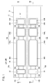
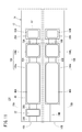
- a gas sensor according to the first embodiment (hereinafter referred to as a first gas sensor 10A) has a sensor element 12 as shown in FIGS. 1 to 3.
- the sensor element 12 has a structure 14 made of an oxygen ion conductive solid electrolyte, and a first sensor cell 15A and a second sensor cell 15B formed in the structure 14.
- the first sensor cells 15A and the second sensor cells 15B are arranged in the horizontal direction in the structure 14 It is provided.
- the first sensor cell 15A is formed in the structure 14, and is formed in the first gas introduction port 16A into which the gas to be measured is introduced, and in the structure 14, and is formed in the first gas introduction port 16A. It has a first oxygen concentration adjustment chamber 18A in communication, and a first measurement chamber 20A formed in the structure 14 and in communication with the first oxygen concentration adjustment chamber 18A.
- the first oxygen concentration adjustment chamber 18A has a first main adjustment chamber 18Aa in communication with the first gas inlet 16A and a first sub adjustment chamber 18Ab in communication with the first main adjustment chamber 18Aa.
- the first measurement chamber 20A communicates with the first auxiliary adjustment chamber 18Ab.
- the first sensor cell 15A is provided between the first gas inlet 16A and the first main adjustment chamber 18Aa in the structure 14 and has a preliminary adjustment chamber 22 communicated with the first gas inlet 16A. .
- the second sensor cell 15B is formed in the structural body 14 and is formed in the structural body 14 with the second gas inlet 16B into which the gas to be measured is introduced. It has a second oxygen concentration adjustment chamber 18B in communication with 16B, and a second measurement chamber 20B formed in the structure 14 and in communication with the second oxygen concentration adjustment chamber 18B.
- the second oxygen concentration adjustment chamber 18B has a second main adjustment chamber 18Ba in communication with the second gas inlet 16B and a second sub adjustment chamber 18Bb in communication with the second main adjustment chamber 18Ba.
- the second measurement chamber 20B is in communication with the second auxiliary adjustment chamber 18Bb.
- the second sensor cell 15B is provided between the second gas introduction port 16B and the second main adjustment chamber 18Ba in the structural body 14, and the diffusion resistance adjustment chamber 24 (in communication with the second gas introduction port 16B) A first chamber of the second sensor cell 15B).
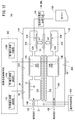
- the structure 14 includes a first substrate layer 26 a, a second substrate layer 26 b, a third substrate layer 26 c, a first solid electrolyte layer 28, and a spacer.
- Six layers of the layer 30 and the second solid electrolyte layer 32 are stacked in this order from the lower side in the drawing view.
- Each layer is composed of an oxygen ion conductive solid electrolyte layer such as zirconia (ZrO 2 ).
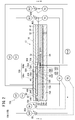
- the first sensor cell 15A is located on the tip end side of the sensor element 12, and between the lower surface of the second solid electrolyte layer 32 and the upper surface of the first solid electrolyte layer 28 is a first gas.
- the inlet 16A, the first diffusion control unit 34A, the preliminary adjustment chamber 22, the second diffusion control unit 36A, the first oxygen concentration adjustment chamber 18A, the third diffusion control unit 38A, and the first measurement chamber 20A Is equipped.
- a fourth diffusion control unit 40A is provided between the first main adjustment chamber 18Aa constituting the first oxygen concentration adjustment chamber 18A and the first sub adjustment chamber 18Ab.
- the first gas inlet 16A, the first diffusion control unit 34A, the preliminary adjustment chamber 22, the second diffusion control unit 36A, the first main adjustment chamber 18Aa, the fourth diffusion control unit 40A, and the first auxiliary The adjustment chamber 18Ab, the third diffusion control unit 38A, and the first measurement chamber 20A are formed adjacent to each other in such a manner as to communicate in this order.
- a portion from the first gas inlet 16A to the first measurement chamber 20A is also referred to as a first gas circulation unit.
- the first gas inlet 16A, the preliminary adjustment chamber 22, the first main adjustment chamber 18Aa, the first auxiliary adjustment chamber 18Ab, and the first measurement chamber 20A are provided in a mode in which the spacer layer 30 is hollowed out. It is a space.
- the preliminary adjustment chamber 22, the first main adjustment chamber 18Aa, the first sub-adjustment chamber 18Ab, and the first measurement chamber 20A are all upper in the lower surface of the second solid electrolyte layer 32 and lower in the first solid. Each side of the upper surface of the electrolyte layer 28 is divided by the side surface of the spacer layer 30.
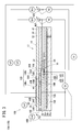
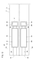
- the second sensor cell 15B As shown in FIG. 3, between the lower surface of the second solid electrolyte layer 32 and the upper surface of the first solid electrolyte layer 28 on the tip end side of the sensor element 12
- the second gas inlet 16B, the first diffusion control unit 34B, the diffusion resistance adjustment chamber 24, the second diffusion control unit 36B, the second oxygen concentration adjustment chamber 18B, the third diffusion control unit 38B, and the second A measuring room 20B is provided.
- a fourth diffusion control unit 40B is provided between the second main adjustment chamber 18Ba constituting the second oxygen concentration adjustment chamber 18B and the second sub adjustment chamber 18Bb.
- the second gas inlet 16B, the first diffusion control unit 34B, the diffusion resistance adjustment chamber 24, the second diffusion control unit 36B, the second main adjustment chamber 18Ba, the fourth diffusion control unit 40B, and the second The sub adjustment chamber 18Bb, the third diffusion control unit 38B, and the second measurement chamber 20B are formed adjacent to each other in such a manner as to communicate in this order.
- a portion from the second gas inlet 16B to the second measurement chamber 20B is also referred to as a second gas circulation unit.
- the second gas inlet 16B, the diffusion resistance adjustment chamber 24, the second main adjustment chamber 18Ba, the second sub adjustment chamber 18Bb, and the second measurement chamber 20B are provided in a mode in which the spacer layer 30 is hollowed out. It is an internal space.
- the diffusion resistance adjusting chamber 24, the second main adjusting chamber 18 Ba, the second sub adjusting chamber 18 Bb, and the second measuring chamber 20 B are all upper in the lower surface of the second solid electrolyte layer 32 and lower in the first Each side of the upper surface of the solid electrolyte layer 28 is divided by the side surface of the spacer layer 30.
- each of the first diffusion rate limiting portion (34A, 34B), the third diffusion rate limiting portion (38A, 38B) and the fourth diffusion rate limiting portion (40A, 40B) is two. It is provided as an elongated slit (the opening has a longitudinal direction in the direction perpendicular to the drawing).
- the second diffusion limiting portion (36A, 36B) is provided as a single long slit (the opening has a longitudinal direction in the direction perpendicular to the drawing).
- first sensor cell 15A and the first sensor cell 15A are positioned between the upper surface of the third substrate layer 26c and the lower surface of the spacer layer 30 and farther from the tip side than the first gas circulation portion and the second gas circulation portion, respectively.
- a reference gas introduction space 41 common to the second sensor cell 15B is provided.
- the reference gas introduction space 41 is an internal space partitioned at the top by the lower surface of the spacer layer 30, at the lower by the upper surface of the third substrate layer 26c, and at the side by the side of the first solid electrolyte layer 28.
- oxygen or air is introduced into the reference gas introduction space 41 as a reference gas.
- the first gas inlet 16A and the second gas inlet 16B are portions that are open to the external space, and the first sensor cell 15A is connected to the external space through the first gas inlet 16A and the second gas inlet 16B. A gas to be measured is taken into the inner and second sensor cells 15B.
- the first diffusion limiting portion 34A of the first sensor cell 15A is a portion that applies a predetermined diffusion resistance to the gas to be measured introduced from the first gas inlet 16A to the preparatory adjustment chamber 22.
- the preliminary adjustment chamber 22 will be described later.
- the first diffusion control part 34B of the second sensor cell 15B is a part that applies a predetermined diffusion resistance to the measurement gas introduced into the diffusion resistance adjustment chamber 24 from the second gas inlet 16B.
- the second diffusion rate control part 36A of the first sensor cell 15A is a part that applies a predetermined diffusion resistance to the measurement gas introduced from the preparatory adjustment chamber 22 to the first main adjustment chamber 18Aa.
- the second diffusion rate control unit 36B of the second sensor cell 15B is a part that applies a predetermined diffusion resistance to the measurement gas introduced from the diffusion resistance adjustment chamber 24 to the second main adjustment chamber 18Ba.
- the first main adjustment chamber 18Aa is provided as a space for adjusting the partial pressure of oxygen in the measurement gas introduced from the first gas inlet 16A.
- the oxygen partial pressure is adjusted by the operation of a first main pump cell 42A described later.
- the second main adjustment chamber 18Ba is provided as a space for adjusting the partial pressure of oxygen in the measurement gas introduced from the second gas inlet 16B.
- the oxygen partial pressure is adjusted by the operation of a second main pump cell 42B described later.
- the first main pump cell 42A includes a first main inner pump electrode 44A, an outer pump electrode 46 common to the first sensor cell 15A and the second sensor cell 15B, and an oxygen ion conductive solid electrolyte sandwiched between these electrodes. It is a 1st electrochemical pump cell (main electrochemical pumping cell) comprised.
- the first main inner pump electrode 44A is provided on substantially the entire surface of the upper surface of the first solid electrolyte layer 28 partitioning the first main adjustment chamber 18Aa, the lower surface of the second solid electrolyte layer 32, and the side surface of the spacer layer 30. It is done.
- the common outer pump electrode 46 extends from the region corresponding to the first main inner pump electrode 44A to the region corresponding to the second main inner pump electrode 44B (the second sensor cell 15B) on the upper surface of the second solid electrolyte layer 32 It is provided in the form exposed to space.
- the first main pump cell 42A applies the first pump voltage Vp1 from the first variable power supply 48A for the first sensor cell provided outside the sensor element 12 to share the common outer pump electrode 46 and the first main inner pump electrode 44A.
- the oxygen in the first main adjustment chamber 18Aa can be pumped out to the outside space, or the oxygen in the outside space can be pumped into the first main adjustment chamber 18Aa by flowing the first pump current Ip1 between them. ing.
- the first sensor cell 15A has a first oxygen partial pressure detection sensor cell 50A which is an electrochemical sensor cell.
- the first oxygen partial pressure detection sensor cell 50A is sandwiched between the first main inner pump electrode 44A, a common reference electrode 52 sandwiched between the upper surface of the third substrate layer 26c and the first solid electrolyte layer 28, and these electrodes. And an oxygen ion conductive solid electrolyte.
- the common reference electrode 52 is made of the same porous cermet as the common outer pump electrode 46 and the like, and is a substantially rectangular electrode in plan view. Further, around the common reference electrode 52, a common reference gas introduction layer 54 made of porous alumina and connected to the common reference gas introduction space 41 is provided.
- the first oxygen partial pressure detection sensor cell 50A has the first main inner pump electrode 44A and the reference electrode 52 due to the difference in oxygen concentration between the atmosphere in the first main adjustment chamber 18Aa and the reference gas in the reference gas introduction space 41. In the meantime, a first electromotive force V1 is generated.
- the first electromotive force V1 generated in the first oxygen partial pressure detection sensor cell 50A changes in accordance with the oxygen partial pressure of the atmosphere present in the first main adjustment chamber 18Aa.
- the first sensor cell 15A performs feedback control of the first variable power supply 48A of the first main pump cell 42A by the first electromotive force V1.
- the first pump voltage Vp1 applied to the first main pump cell 42A by the first variable power source 48A can be controlled according to the oxygen partial pressure of the atmosphere of the first main adjustment chamber 18Aa.
- the fourth diffusion limiting portion 40A applies a predetermined diffusion resistance to the gas to be measured whose oxygen concentration (oxygen partial pressure) is controlled by the operation of the first main pump cell 42A in the first main adjustment chamber 18Aa, It is a site
- the first sub-adjustment chamber 18Ab After the oxygen concentration (oxygen partial pressure) is adjusted in advance in the first main adjustment chamber 18Aa, the first sub-adjustment chamber 18Ab will be described later with respect to the gas to be measured introduced through the fourth diffusion control unit 40A. (1) It is provided as a space for adjusting the partial pressure of oxygen by the auxiliary pump cell 56A. As a result, the oxygen concentration in the first auxiliary adjustment chamber 18Ab can be kept constant with high accuracy, so that the first sensor cell 15A can perform NOx concentration measurement with high accuracy.
- the first auxiliary pump cell 56A is an electrochemical pump cell, and is common to the first auxiliary pump electrode 58A provided on substantially the entire lower surface of the second solid electrolyte layer 32 facing the first auxiliary adjustment chamber 18Ab.
- An electrode 46 and a second solid electrolyte layer 32 are provided.
- the first auxiliary pump electrode 58A is also formed using a material having a reduced ability to reduce NOx components in the measurement gas, as in the first main inner pump electrode 44A.
- the first auxiliary pump cell 56A applies the desired second voltage Vp2 between the first auxiliary pump electrode 58A and the outer pump electrode 46 to transfer oxygen in the atmosphere in the first auxiliary adjustment chamber 18Ab to the external space. It is possible to pump or to pump into the first auxiliary control chamber 18Ab from the outside space.
- the first auxiliary pump electrode 58A, the reference electrode 52, the second solid electrolyte layer 32, the spacer layer 30, and the first The solid electrolyte layer 28 and the electrochemical sensor cell, that is, the second oxygen partial pressure detection sensor cell 50B for controlling the first auxiliary pump are configured.
- the first auxiliary pump cell 56A performs pumping with the second variable power supply 48B that is voltage-controlled based on the second electromotive force V2 detected by the second oxygen partial pressure detection sensor cell 50B.
- the oxygen partial pressure in the atmosphere in the first auxiliary adjustment chamber 18Ab is controlled to a low partial pressure that does not substantially affect the measurement of NOx.
- the second pump current value Ip2 of the first auxiliary pump cell 56A is used to control the second electromotive force V2 of the second oxygen partial pressure detection sensor cell 50B.
- the second pump current Ip2 is input as a control signal to the second oxygen partial pressure detection sensor cell 50B, and the second electromotive force V2 is controlled, whereby the first auxiliary current is transmitted through the fourth diffusion control unit 40A.
- the gradient of the oxygen partial pressure in the measurement gas introduced into the adjustment chamber 18Ab is controlled to be constant at all times.
- the first variable power supply 48A of the first main pump cell 42A is feedback-controlled so that the second pump current value Ip2 becomes constant, the accuracy of oxygen partial pressure control in the first sub adjustment chamber 18Ab is further improved. .
- the oxygen concentration in the first auxiliary adjustment chamber 18Ab is accurately adjusted to a predetermined value of each condition by the actions of the first main pump cell 42A and the first auxiliary pump cell 56A. Will be kept.
- the third diffusion rate control unit 38A applies a predetermined diffusion resistance to the gas to be measured whose oxygen concentration (oxygen partial pressure) is controlled by the operation of the first auxiliary pump cell 56A in the first auxiliary adjustment chamber 18Ab, It is a part which leads gas to the 1st measurement room 20A.
- the first measurement pump cell 60A is an electrochemical device including the first measurement electrode 62A, the common outer pump electrode 46, the second solid electrolyte layer 32, the spacer layer 30, and the first solid electrolyte layer 28. It is a pump cell.
- the first measurement electrode 62A is provided directly on, for example, the upper surface of the first solid electrolyte layer 28 in the first measurement chamber 20A, and has a reduction ability with respect to the NOx component in the measurement gas compared to the first main inner pump electrode 44A. It is a porous cermet electrode composed of an enhanced material.
- the first measurement electrode 62A also functions as a NOx reduction catalyst that reduces NOx present in the atmosphere on the first measurement electrode 62A.
- the first measurement pump cell 60A pumps out oxygen generated by the decomposition of nitrogen oxides in the atmosphere (in the first measurement chamber 20A) around the first measurement electrode 62A, and the amount of generation thereof is the third pump current value Ip3. That is, it can be detected as the sensor output (first measurement pump current value Ip3) of the first sensor cell 15A.
- a third oxygen partial pressure detection sensor cell 50C for measuring pump control is configured.
- the third variable power supply 48C is controlled based on the third electromotive force V3 detected by the third oxygen partial pressure detection sensor cell 50C.
- the measurement gas introduced into the first auxiliary adjustment chamber 18Ab reaches the first measurement electrode 62A in the first measurement chamber 20A through the third diffusion control unit 38A under the control of the oxygen partial pressure.
- the nitrogen oxides in the gas to be measured around the first measurement electrode 62A are reduced to generate oxygen.
- the generated oxygen is pumped by the first measurement pump cell 60A.
- the third voltage Vp3 of the third variable power supply 48C is controlled such that the third electromotive force V3 detected by the third oxygen partial pressure detection sensor cell 50C becomes constant.
- the amount of oxygen generated around the first measurement electrode 62A is proportional to the concentration of nitrogen oxides in the measurement gas. Therefore, the nitrogen oxide concentration in the gas to be measured can be calculated using the first measurement pump current value Ip3 of the first measurement pump cell 60A. That is, the first measurement pump cell 60A measures the concentration of the specific component (NO) in the first measurement chamber 20A.
- the first heater 72A is formed in a mode in which the first sensor cell 15A is vertically sandwiched between the second substrate layer 26b and the third substrate layer 26c.
- the first heater 72A generates heat by being supplied with power from the outside through a heater electrode (not shown) provided on the lower surface of the first substrate layer 26a.
- the heat generation of the first heater 72A enhances the oxygen ion conductivity of the solid electrolyte constituting the first sensor cell 15A.
- the first heater 72A is embedded throughout the preliminary adjustment chamber 22, the oxygen concentration adjustment chamber 18, and the first measurement chamber 20A, and heats and maintains a predetermined place of the first sensor cell 15A to a predetermined temperature. It can be done.
- a first heater insulating layer 74A made of alumina or the like is formed on the upper and lower surfaces of the first heater 72A for the purpose of obtaining electrical insulation between the second substrate layer 26b and the third substrate layer 26c.
- the preliminary adjustment chamber 22 functions as a space for adjusting the oxygen partial pressure in the measurement gas introduced from the first gas inlet 16A.
- the oxygen partial pressure is adjusted by the operation of a preliminary pump cell 80 described later.
- the preliminary pump cell 80 includes a preliminary pump electrode 82 provided on substantially the entire lower surface of the second solid electrolyte layer 32 facing the preliminary adjustment chamber 22, an outer pump electrode 46, and a second solid electrolyte layer 32. , Is a preliminary electrochemical pump cell.
- the spare pump electrode 82 is also formed using a material having a reduced ability to reduce NOx components in the gas to be measured, as with the first main inner pump electrode 44A.
- the preliminary pump cell 80 pumps the oxygen in the atmosphere in the preconditioning chamber 22 to the external space by applying a desired preliminary voltage Vp 0 between the preliminary pump electrode 82 and the outer pump electrode 46, or from the external space It is possible to pump into the preparatory chamber 22.
- the first sensor cell 15A has a preliminary oxygen partial pressure detection sensor cell 84 for preliminary pump control in order to control the partial pressure of oxygen in the atmosphere in the preliminary adjustment chamber 22.
- the preliminary oxygen partial pressure detection sensor cell 84 has a preliminary pump electrode 82, a reference electrode 52, a second solid electrolyte layer 32, a spacer layer 30, and a first solid electrolyte layer 28.
- the spare pump cell 80 pumps with the spare variable power supply 86 that is voltage-controlled based on the spare electromotive force V0 detected by the spare oxygen partial pressure detection sensor cell 84. Thereby, the partial pressure of oxygen in the atmosphere in the preconditioning chamber 22 is controlled to a low partial pressure which has substantially no influence on the measurement of NOx.
- the preliminary pump current value Ip 0 is used to control the electromotive force of the preliminary oxygen partial pressure detection sensor cell 84.
- the preliminary pump current Ip0 is input as a control signal to the preliminary oxygen partial pressure detection sensor cell 84, and the preliminary electromotive force V0 is controlled, whereby the first diffusion control unit 34A enters the preliminary adjustment chamber 22.
- the gradient of oxygen partial pressure in the gas to be measured to be introduced is controlled to be constant at all times.
- the preliminary adjustment chamber 22 also functions as a buffer space. That is, it is possible to cancel out the concentration fluctuation of the measurement gas caused by the pressure fluctuation of the measurement gas in the external space (the pulsation of the exhaust pressure if the measurement gas is the exhaust gas of a car).
- the second sensor cell 15B includes the second main pump cell 42B, the second auxiliary pump cell 56B, the fourth oxygen partial pressure detection sensor cell 50D, the fifth oxygen partial pressure detection sensor cell 50E, and the sixth oxygen partial pressure It has a detection sensor cell 50F.
- the second main pump cell 42B includes a second main inner pump electrode 44B, a common outer pump electrode 46, and an oxygen ion conductive solid electrolyte sandwiched between these electrodes. And a second electrochemical pump cell (main electrochemical pumping cell).
- the fourth pump voltage Vp4 is applied by the fourth variable power supply 48D for the second sensor cell, and the fourth pump current Ip4 is caused to flow between the common outer pump electrode 46 and the second main inner pump electrode 44B.
- the oxygen in the main adjustment chamber 18Ba can be pumped out to the outside space, or the oxygen in the outside space can be pumped into the second main adjustment chamber 18Ba.
- the second auxiliary pump cell 56B is an electrochemical pump cell, and is provided on substantially the entire lower surface of the second solid electrolyte layer 32 facing the second auxiliary adjustment chamber 18Bb.
- a secondary auxiliary pump electrode 58 B, a common outer pump electrode 46 and a second solid electrolyte layer 32 are provided.
- the second auxiliary pump cell 56B applies the desired fifth voltage Vp5 between the second auxiliary pump electrode 58B and the outer pump electrode 46 to transfer oxygen in the atmosphere in the second auxiliary adjustment chamber 18Bb to the external space. It is possible to pump out or to pump into the second auxiliary control chamber 18Bb from the outside space.
- the fourth oxygen partial pressure detection sensor cell 50D is commonly held between the second main inner pump electrode 44B, the upper surface of the third substrate layer 26c, and the first solid electrolyte layer 28.
- the fourth oxygen partial pressure detection sensor cell 50D has the second main inner pump electrode 44B and the reference electrode due to the difference in oxygen concentration between the atmosphere in the second main adjustment chamber 18Ba and the reference gas in the reference gas introduction space 41.
- a fourth electromotive force V4 is generated between the voltage 52 and the voltage 52.
- the fourth electromotive force V4 generated in the fourth oxygen partial pressure detection sensor cell 50D changes in accordance with the oxygen partial pressure of the atmosphere present in the second main adjustment chamber 18Ba.
- the second sensor cell 15B performs feedback control of the fourth variable power supply 48D of the second main pump cell 42B by the fourth electromotive force V4.
- the fourth pump voltage Vp4 applied to the second main pump cell 42B by the fourth variable power supply 48D can be controlled according to the oxygen partial pressure of the atmosphere of the second main adjustment chamber 18Ba.
- the second auxiliary pump electrode 58B in order to control the oxygen partial pressure in the atmosphere in the second auxiliary adjustment chamber 18Bb, the second auxiliary pump electrode 58B, the reference electrode 52, the second solid electrolyte layer 32, the spacer layer 30, and the first An electrochemical sensor cell, that is, a fifth oxygen partial pressure detection sensor cell 50E for controlling the second auxiliary pump is constituted by the solid electrolyte layer 28.
- the second auxiliary pump cell 56B performs pumping with the fifth variable power supply 48E that is voltage-controlled based on the fifth electromotive force V5 detected by the fifth oxygen partial pressure detection sensor cell 50E.
- the oxygen partial pressure in the atmosphere in the second auxiliary adjustment chamber 18Bb is controlled to a low partial pressure that does not substantially affect the measurement of NOx.
- the fifth pump current value Ip5 of the second auxiliary pump cell 56B is used to control the fifth electromotive force V5 of the fifth oxygen partial pressure detection sensor cell 50E. That is, the gradient of the oxygen partial pressure in the measurement gas introduced into the second auxiliary adjustment chamber 18Bb is controlled to be constant at all times.
- a sensor cell that is, a sixth oxygen partial pressure detection sensor cell 50F for measuring pump control is configured.
- the sixth variable power supply 48F is controlled based on the sixth electromotive force V6 detected by the sixth oxygen partial pressure detection sensor cell 50F.
- the measurement gas introduced into the second auxiliary adjustment chamber 18Bb reaches the second measurement electrode 62B in the second measurement chamber 20B through the third diffusion control unit 38B under the control of the oxygen partial pressure.
- the nitrogen oxides in the gas to be measured around the second measurement electrode 62B are reduced to generate oxygen.
- the generated oxygen is pumped by the second measurement pump cell 60B.
- the sixth voltage Vp6 of the sixth variable power supply 48F is controlled such that the sixth electromotive force V6 detected by the sixth oxygen partial pressure detection sensor cell 50F becomes constant.
- the amount of oxygen generated around the second measurement electrode 62B is proportional to the concentration of nitrogen oxides in the measurement gas. Therefore, the nitrogen oxide concentration in the gas to be measured can be calculated using the second measurement pump current value Ip6 of the second measurement pump cell 60B. That is, the second measurement pump cell 60B measures the concentration of the specific component (NO) in the second measurement chamber 20B.
- the second sensor cell 15B has an electrochemical oxygen detection cell 70.
- the oxygen detection cell 70 includes a second solid electrolyte layer 32, a spacer layer 30, a first solid electrolyte layer 28, a third substrate layer 26 c, an outer pump electrode 46, and a reference electrode 52.
- the partial pressure of oxygen in the gas to be measured outside the sensor element 12 can be detected by the electromotive force Vr obtained by the oxygen detection cell 70.
- the second heater 72B similar to the first heater 72A described above is formed in a mode in which the second sensor cell 15B is vertically sandwiched by the second substrate layer 26b and the third substrate layer 26c.
- the second heater 72B is embedded throughout the diffusion resistance adjustment chamber 24, the second oxygen concentration adjustment chamber 18B, and the first measurement chamber 20A, and heats a predetermined location of the second sensor cell 15B to a predetermined temperature, It can be kept warm.
- a second heater insulating layer 74B made of alumina or the like is also formed on the upper and lower surfaces of the second heater 72B in order to obtain electrical insulation between the second substrate layer 26b and the third substrate layer 26c.
- the first heater 72A and the second heater 72B may be configured by one common heater, and in this case, the first heater insulating layer 74A and the second heater insulating layer 74B are also common.
- the diffusion resistance adjusting chamber 24 also functions as a buffer space. That is, it is possible to cancel out the concentration fluctuation of the measurement gas caused by the pressure fluctuation of the measurement gas in the external space (the pulsation of the exhaust pressure if the measurement gas is the exhaust gas of a car).
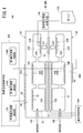
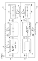
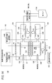
- the first gas sensor 10A includes a temperature control unit 100, an oxygen concentration control unit 102, and a target component concentration acquisition unit 104.
- the temperature control means 100 controls energization of the first heater 72A and the second heater 72B of the sensor element 12 to control the temperatures of the first sensor cell 15A and the second sensor cell 15B.
- the oxygen concentration control means 102 controls the oxygen concentration in the first oxygen concentration adjustment chamber 18A of the first sensor cell 15A, and the oxygen in the second oxygen concentration adjustment chamber 18B of the second sensor cell 15B.
- the target component concentration acquisition means 104 includes a first measurement pump current value Ip3 flowing to the first measurement pump cell 60A of the first sensor cell 15A and a second measurement pump current value Ip6 flowing to the second measurement pump cell 60B of the second sensor cell 15B.
- first target component (NO) and the second target component (NH 3 ) based on the difference (change amount ⁇ Ip) the second measurement pump current value Ip6 (total concentration), and the first map 110A described later.
- the temperature control unit 100, the oxygen concentration control unit 102, and the target component concentration acquisition unit 104 are constituted by, for example, one or more CPUs (central processing units) and one or more electronic circuits having a storage device and the like.
- the electronic circuit is also a software function unit in which a predetermined function is realized by the CPU executing a program stored in, for example, a storage device.
- an integrated circuit such as a field-programmable gate array (FPGA) may be formed by connecting a plurality of electronic circuits in accordance with the function.
- FPGA field-programmable gate array
- the NOx sensor with a conventional in-line two-chamber structure converts all of the target components of NO and NH 3 into NO in the oxygen concentration adjustment chamber, and then introduces it into the measurement chamber to measure the total amount of these two components. It was That is, it was not possible to measure the concentration of each of the two target components, that is, the concentrations of NO and NH 3 .
- the first gas sensor 10A is first sensor cell 15A described above, the second sensor cell 15B, by including a temperature control means 100, the oxygen concentration control means 102 and the target component concentration acquiring unit 104, NO and NH 3 Of each concentration can be obtained.
- the temperature control means 100 sets the first heater 72A and the second heater 72B based on the conditions of the sensor temperature set in advance and the measurement value from the temperature sensor (not shown) that measures the temperature of the sensor element 12. By feedback control, the temperature of the sensor element 12 is adjusted to the temperature according to the above conditions.
- the first oxygen concentration control unit 106A of the oxygen concentration control means 102 generates the conditions of the oxygen concentration in the first oxygen concentration adjustment chamber 18A set in advance and the first oxygen partial pressure detection sensor cell 50A (see FIG. 2).
- the oxygen concentration in the first oxygen concentration adjusting chamber 18A is adjusted to a concentration according to the above condition by feedback control of the first variable power supply 48A based on the one electromotive force V1.
- the second oxygen concentration control unit 106B of the oxygen concentration control means 102 generates the condition of the oxygen concentration in the second oxygen concentration adjustment chamber 18B set in advance and the fourth oxygen partial pressure detection sensor cell 50D (see FIG. 3).
- the oxygen concentration in the second oxygen concentration adjustment chamber 18B is adjusted to a concentration according to the above conditions by feedback control of the fourth variable power supply 48D based on the four electromotive forces V4.
- the first gas sensor 10A uses the oxygen concentration control means 102 or the temperature control means 100, or the oxygen concentration control means 102 and the temperature control means 100 to generate NO in the first oxygen concentration adjustment chamber 18A and the second oxygen concentration adjustment chamber 18B. Control to convert NH 3 to NO at a rate that can be used for NH 3 measurement without decomposing it.
- the preliminary oxygen concentration control unit 108 of the oxygen concentration control means 102 sets the preliminary variable power supply based on the preset oxygen concentration condition and the preliminary electromotive force V0 generated in the preliminary oxygen partial pressure detection sensor cell 84 (see FIG. 2).
- the oxygen concentration in the preconditioning chamber 22 is adjusted to the concentration according to the conditions.
- This preliminary oxygen concentration control unit 108 without decomposing NO preconditioning chamber 22 in the first sensor cell 15A, NH 3 is converted to NO in a ratio that can be used for NH 3 measurement.
- NH 3 introduced into the preconditioning chamber 22 through the first gas inlet 16A undergoes an oxidation reaction of NH 3 ⁇ NO in the preconditioning chamber 22, All NH 3 introduced through the 1 gas inlet 16A is converted to NO. Accordingly, NH 3 is passed through the diffusion coefficient 2.2 cm 2 / sec of the NH 3 to the first diffusion control part 34A, the diffusion coefficient of the second diffusion rate-determining section 36A after the NO in from preconditioning chamber 22 to the back 1. It moves to the first measurement chamber 20A at a speed of 8 cm 2 / sec.
- the oxygen concentration control means 102 since it is controlled so as to convert all NH 3 NO, NH 3 flowing into the second oxygen concentration adjusting chamber 18B In the second oxygen concentration adjustment chamber 18B, an oxidation reaction of NH 3 ⁇ NO occurs, and all NH 3 in the second oxygen concentration adjustment chamber 18B is converted to NO.
- NH 3 introduced through the second gas inlet 16 B passes through the first diffusion control part 34 B and the second diffusion control part 36 B at a rate of a diffusion coefficient of 2.2 cm 2 / sec of NH 3 , and the second oxygen After being converted into NO in the concentration adjustment chamber 18B, it passes through the third diffusion-controlled portion 38B at a speed of a diffusion coefficient of NO of 1.8 cm 2 / sec, and moves into the adjacent second measurement chamber 20B.
- the second sensor cell 15B, where the oxidation reaction of NH 3 occurs is a second oxygen concentration adjusting chamber 18B.
- the second diffusion control part (36A, 36B) or through NO the of differences through with NH 3, the first measurement chamber 20A and the second measurement chamber This corresponds to the difference in the amount of NO flowing into 20B.
- the second measurement pump current value Ip6 of the second measurement pump cell 60B corresponds to the total value of the NH 3 concentration and the NO concentration in the measurement gas.
- the amount of change ⁇ Ip between the first measurement pump current value Ip3 and the second measurement pump current value Ip6 changes according to the concentration of NH 3 in the gas to be measured. Therefore, obtaining a second measured pump current flowing through the second measuring pumping cell 60B Ip6 (total concentration of NO and NH 3), each concentration of NO and NH 3 from the above-mentioned amount of change Delta] Ip (concentration of NH 3) can do.
- the target component concentration acquisition means 104 (see FIG. 4), the amount of change ⁇ Ip between the first measurement pump current value Ip3 and the second measurement pump current value Ip6, the second measurement pump current value Ip6, for example, the first map Each concentration of NO and NH 3 is obtained based on 110A (see FIG. 6).
- the second measurement pump current value Ip6 ( ⁇ A) is set on the horizontal axis, and the first measurement pump current value Ip3 and the first measurement pump current value Ip3 are on the vertical axis.
- FIG. 6 representatively, the first plot line P1 and the second plot group P2 of the first characteristic line L1 and the second characteristic line L2 and the NO concentration conversion value of the variation ⁇ Ip in the 100 ppm system, 50 ppm system and 25 ppm system. And a third plot group P3.
- the first characteristic line L1 changes the concentration conversion value of NH 3 to 0 ppm, 25 ppm, 50 ppm, 75 ppm and 100 ppm when the concentration conversion value of NO is 0 ppm, that is, when NO is contained in the measurement gas. It shows the characteristics when it is made to
- the second characteristic line L 2 sets the concentration conversion value of NO to 0 ppm, 25 ppm, 50 ppm, 75 ppm and 100 ppm. It shows the characteristics when changed.
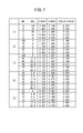
- the contents of the first column [1] correspond to the first characteristic line L1 of FIG. 6, and the contents of the second column [2] correspond to the second characteristic line L2 of FIG.
- the comparison of [1] and [2] shows that NH 3 has a sensitivity 1.14 times that of NO. This occurs based on the difference in diffusion coefficient between NH 3 and NO, and is determined by the temperature of the sensor element 12 and the oxygen concentration in the internal space.
- the contents of the third column [3] correspond to the first plot group P1 of FIG. 6, and the contents of the fourth column [4] correspond to the second plot group P2 of FIG.
- the contents of the fifth column [5] correspond to the third plot group P3 of FIG.
- the total concentration (NO conversion value) based on the second measurement pump current value Ip6 That is, one of 100 ppm system, 50 ppm system and 25 ppm system is determined, the NH 3 concentration is obtained based on the variation ⁇ Ip, and the NH 3 concentration is subtracted from the total concentration to obtain the NO concentration.
- the second measurement pump current value Ip6 is 0.537 ( ⁇ A)
- the total concentration is 25 ppm system.
- the change amount ⁇ Ip was 0.041 ( ⁇ A)
- the nearest change amount ⁇ Ip is specified on the map to calculate the total concentration, and for example, the NH 3 concentration is obtained by known approximation calculation. Good. Then, the NH 3 concentration may be subtracted from the calculated total concentration to obtain the NO concentration.
- NH 3, NO each concentration and Delta] Ip and to calculate the concentration of NH 3 which is a second target component based on the correlation equation between Ip6, by subtracting the concentration of the second target component from the total concentration, first The concentration of NO which is the target component may be calculated.
- the sensor element 12 described above is manufactured, metal parts are assembled into a sensor shape, attached to the Dell gas measuring apparatus, and the sensor element 12 is assembled by the first heater 72A and the second heater 72B built in the sensor element 12. Heat to approximately 800 ° C.
- the electromotive force between the first measurement electrode 62A and the reference electrode 52 of the first measurement pump cell 60A in the first sensor cell 15A, and the second measurement electrode 62B of the second measurement pump cell 60B in the second sensor cell 15B The voltage applied between the first measurement electrode 62A and the outer pump electrode 46 and the voltage applied between the second measurement electrode 62B and the outer pump electrode 46 are feedback controlled so that the electromotive force between the reference electrodes 52 is 400 mV. .
- the voltage applied between the spare pump electrode 82 and the outer pump electrode 46 is feedback-controlled so that the electromotive force between the spare pump electrode 82 of the spare pump cell 80 and the reference electrode 52 in the first sensor cell 15A becomes 230 mV.
- the relationship between the concentration of each NO and NH 3 , the first measurement pump current value Ip 3 and the second measurement pump current Ip 6, and the difference (change amount ⁇ Ip) between the first measurement pump current Ip 3 and the second measurement pump current Ip 6 is shown in FIG.
- the second plot group P2 is shown in the fourth column [4] of Table 1 in FIG.
- the sensor element 12 having the structure 14 made of at least the oxygen ion conductive solid electrolyte, and the first sensor cell 15A and the second sensor cell 15B formed in the structure 14; It has temperature control means 100 for controlling the temperature of the sensor element 12, oxygen concentration control means 102, and target component concentration acquisition means 104.
- the first sensor cell 15A has a first gas inlet 16A, a first diffusion control unit 34A, a preliminary adjustment chamber 22, a second diffusion control unit 36A, a first oxygen concentration adjustment chamber 18A, and a third sensor cell 15A in the gas introduction direction.
- a diffusion control unit 38A and a first measurement chamber 20A are provided.
- the second sensor cell 15B has a second gas introduction port 16B, a first diffusion control unit 34B, a diffusion resistance adjustment chamber 24, a second diffusion control unit 36B, a second oxygen concentration adjustment chamber 18B, and a second sensor cell 15B in the gas introduction direction.
- a diffusion control unit 38B and a second measurement chamber 20B are provided.
- the first measurement chamber 20A of the first sensor cell 15A includes the first measurement pump cell 60A
- the second measurement chamber 20B of the second sensor cell 15B includes the second measurement pump cell 60B.
- the oxygen concentration control means 102 controls the oxygen concentration of the preliminary adjustment chamber 22 of the first sensor cell 15A and the first oxygen concentration adjustment chamber 18A and the oxygen concentration of the second oxygen concentration adjustment chamber 18B of the second sensor cell 15B.
- the target component concentration acquiring unit 104 determines the difference between the first measurement pump current value Ip3 flowing to the first measurement pump cell 60A and the second measurement pump current value Ip6 flowing to the second measurement pump cell 60B (change amount ⁇ Ip).
- the concentration of the second target component (for example, NH 3 ) is acquired based on the second measurement pump current value Ip6 flowing to the second measurement pump cell 60B, and the first target component (for example, NO) and the second target component (for example, The total concentration of NH 3 ) is obtained, and the concentration of the second target component is subtracted from the total concentration to obtain the concentration of the first target component.
- the first gas sensor 10A has such a configuration, even in the atmosphere of a plurality of target components (for example, NO, NH 3 ) coexisting in the presence of unburned components such as exhaust gas and oxygen, the plurality of target components Can be measured accurately over a long period of time.
- a plurality of target components for example, NO, NH 3
- the first gas sensor 10A does not separately perform processing for measuring the concentrations of NO and NH 3 which can not be realized conventionally, and various control devices as hardware, etc., of the control system of the first gas sensor 10A. It can be easily realized simply by changing the software. As a result, it is possible to increase the accuracy with respect to control and failure detection of the NOx purification system. In particular, it is possible to distinguish between NO and NH 3 in the exhaust gas downstream of the SCR system, which contributes to the precise control of the urea injection amount of the SCR system and the detection of deterioration.
- the number of lead wires can be reduced, and for example, mounting on various vehicles can be facilitated.
- the reference electrode 52 disposed in the reference gas introduction space 41 of the first sensor cell 15A and the reference electrode 52 disposed in the reference gas introduction space 41 of the second sensor cell 15B are shared, the number of lead wires can be reduced. This makes it easy to mount on cars and the like.
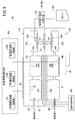
- a gas sensor according to the second embodiment (hereinafter, referred to as a second gas sensor 10B) will be described with reference to FIGS. 9 and 10.
- the second gas sensor 10B includes the second sensor element 12B having the same configuration as the first sensor element 12A of the first gas sensor 10A described above, as shown in FIGS.
- the second target component is NO 2 and the concentration of the first target component (NO) and the concentration of the second target component (NO 2 ) are acquired based on the second map 110B. It is different.
- the second gas sensor 10B is controlled by the oxygen concentration control means 102 or the temperature control means 100, or the oxygen concentration control means 102 and the temperature control means 100, in the first oxygen concentration adjusting chamber 18A and the second oxygen concentration adjusting chamber 18B. Control to convert all NO 2 into NO without decomposing NO of.
- the preliminary oxygen concentration control unit 108 of the oxygen concentration control means 102 sets the preliminary variable power supply based on the preset oxygen concentration condition and the preliminary electromotive force V0 generated in the preliminary oxygen partial pressure detection sensor cell 84 (see FIG. 2). By feedback control of 86, the oxygen concentration in the preconditioning chamber 22 is adjusted to the concentration according to the conditions.
- the preliminary oxygen concentration control unit 108 converts all NO 2 into NO without decomposing NO in the preliminary adjustment chamber 22 in the first sensor cell 15A.
- the NO 2 introduced into the preconditioning chamber 22 through the first gas inlet 16A undergoes a decomposition reaction of NO 2 ⁇ NO in the preconditioning chamber 22. All the NO 2 introduced through the 1 gas inlet 16A is converted to NO.
- the NO 2 introduced through the second gas inlet 16B reaches the second oxygen concentration adjustment chamber 18B.
- the second oxygen concentration adjustment chamber 18B since all the NO 2 is controlled to be converted to NO by the second oxygen concentration control unit 106B of the oxygen concentration control means 102, it flows into the second oxygen concentration adjustment chamber 18B. is the NO 2 takes place decomposition reaction of NO 2 ⁇ NO in the second oxygen concentration adjusting chamber 18B, all NO 2 of the second oxygen concentration adjusting chamber 18B is converted to NO. Therefore, the NO 2 introduced through the second gas inlet 16B passes through the first diffusion control part 34B and the second diffusion control part 36B at the speed of the diffusion coefficient of NO 2 in the second oxygen concentration adjustment chamber 18B. After being converted into NO, it passes through the third diffusion-controlled portion 38B at the speed of the diffusion coefficient of NO, and moves into the adjacent second measurement chamber 20B.
- the place where the decomposition reaction of NO 2 occurs is the preconditioning chamber 22, and in the second sensor cell 15B, the place where the decomposition reaction of NO 2 occurs is the second oxygen concentration adjustment room 18B. Since NO and NO 2 have different diffusion coefficients, the difference between whether NO or NO 2 passes through the second diffusion-controlled portion (36A, 36B) is the first measurement chamber 20A and the second measurement chamber This corresponds to the difference in the amount of NO flowing into 20B. This causes a difference between the first measurement pump current value Ip3 of the first measurement pump cell 60A and the second measurement pump current value Ip6 of the second measurement pump cell 60B. However, the second measurement pump current value Ip6 of the second measurement pump cell 60B corresponds to the total value of the NO 2 concentration and the NO concentration in the measurement gas.
- the amount of change ⁇ Ip between the first measurement pump current value Ip3 and the second measurement pump current value Ip6 is uniquely determined by the concentration of NO 2 in the gas to be measured. Therefore, obtaining a second measured pump current Ip6 (total concentration of NO and NO 2) flowing through the second measuring pumping cell 60B, the respective concentrations of from the above-mentioned amount of change Delta] Ip (concentration of NO 2) NO and NO 2 can do.
- the target component concentration acquiring means 104 the amount of change ⁇ Ip between the first measurement pump current value Ip3 and the second measurement pump current value Ip6, the second measurement pump current value Ip6, and the second map 110B (see FIG. 9). And each concentration of NO 2 and NO 2 is obtained.
- the horizontal axis indicates the second measurement.
- a graph in which the pump current value Ip6 ( ⁇ A) is set, and the variation ⁇ Ip ( ⁇ A) between the first measurement pump current value Ip3 and the second measurement pump current value Ip6 is set on the vertical axis, that is, the second gas sensor 10B Can create graphs and tables corresponding to
- the second gas sensor 10B has such a configuration, even in the atmosphere of a plurality of target components (for example, NO and NO 2 ) coexisting in the presence of unburned components such as exhaust gas and oxygen, the plurality of target components Can be measured accurately over a long period of time.
- a plurality of target components for example, NO and NO 2
- unburned components such as exhaust gas and oxygen
- the second gas sensor 10B does not separately perform processing for measuring each concentration of NO and NO 2 which can not be realized conventionally, and various control devices as hardware, etc., for the control system of the second gas sensor 10B. It can be easily realized simply by changing the software. As a result, it is possible to increase the accuracy with respect to control and failure detection of the NOx purification system. In particular, it is possible to distinguish between NO and NO 2 in exhaust gas downstream of a DOC (Diesel Oxidation Catalyst) catalyst, which contributes to detection of deterioration of the DOC catalyst.
- DOC Diesel Oxidation Catalyst
- FIG. 10C a gas sensor according to the third embodiment (hereinafter referred to as a third gas sensor 10C) will be described with reference to FIGS. 11 and 12.
- FIG. 10C a gas sensor according to the third embodiment
- the third gas sensor 10C is configured such that the diffusion resistance value of the first diffusion-controlled portion 34B of the second sensor cell 15B in the first gas sensor 10A described above (see FIGS. It is an element structure at the time of adjusting substantially equal to the total value of the diffusion resistance value of the 1st gas introduction port 16A of 1 sensor cell 15A, the 1st diffusion control part 34A, the preparatory adjustment room 22, and the 2nd diffusion control part 36A.
- the diffusion resistance adjustment chamber 24 of the second sensor cell 15B and the second diffusion limiting portion 36B are omitted, and a simple structure, for example, when attached to a vehicle An element structure resistant to thermal shock can be provided.
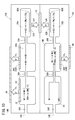
- FIG. 10D a gas sensor according to the fourth embodiment (hereinafter referred to as a fourth gas sensor 10D) will be described with reference to FIGS. 13 and 14.
- FIG. 10D a gas sensor according to the fourth embodiment
- the fourth gas sensor 10D omits the first sensor cell 15A to the fourth diffusion control portion 40A and the first sub adjustment chamber 18Ab of the first gas sensor 10A (see FIGS. 1 and 4) described above. . Instead, the first oxygen concentration adjustment chamber 18A and the first measurement chamber 20A are directly in communication via the third diffusion control unit 38A.
- the diffusion resistance adjustment chamber 24, the second diffusion control unit 36B, the fourth diffusion control unit 40B and the second sub adjustment chamber 18Bb are omitted from the second sensor cell 15B of the first gas sensor 10A (see FIGS. 1 and 4). .
- the second gas inlet 16B and the second oxygen concentration adjustment chamber 18B are directly communicated with each other through the first diffusion control unit 34B, and the second oxygen concentration adjustment chamber 18B and the second measurement chamber 20B are directly connected to the third. Communication is made via the diffusion control portion 38B.
- the oxygen concentration correction means effective for correcting the first measurement pump current Ip3 and the second measurement pump current Ip6 is added to the oxygen concentration control means 102 or the target component concentration acquisition means 104.
- a gas sensor according to the fifth embodiment (hereinafter, referred to as a fifth gas sensor 10E) will be described with reference to FIG.
- the first sensor cell 15A and the second sensor cell 15B need not necessarily be formed on the same plane, and the stacking direction of the solid electrolyte substrate with the heating means (the heater 72 and the heater insulating layer 74) interposed, that is, the thickness direction of the sensor element 12 It may be arranged symmetrically. In this case, the dimension in the width direction of the sensor element 12 can be reduced, which is effective in miniaturizing the sensor element 12.
- the gist of the present invention is the following (a) to (c), and the reaction in which NH 3 or NO 2 is changed to NO can be arbitrarily selected from the range in which fluctuation of sensor output can be obtained.
- a reaction in which NH 3 or NO 2 is changed to NO is intentionally generated before and after a diffusion-limited portion having a predetermined diffusion resistance.
- B According to (a), the concentration of NH 3 or NO 2 is obtained from the fluctuation of the sensor output caused by the difference in diffusion coefficient between NO and NH 3 or NO and NO 2 .
- C further, to obtain a NO concentration by comparing the concentration of NH 3 or NO 2 obtained total concentration of NO and NH 3 obtained by the sensor output itself, or a total concentration of NO and NO 2 by the variation.
- the gas sensor according to the present invention is not limited to the above-described embodiment, and it goes without saying that various configurations can be adopted without departing from the scope of the present invention.
- the first measurement chamber 20A is provided adjacent to the first auxiliary adjustment chamber 18Ab, and the first measurement electrode 62A is disposed in the first measurement chamber 20A.
- the first measurement electrode 62A is disposed in the first auxiliary adjustment chamber 18Ab, and alumina (Al 2 O 3 ) or the like which becomes the third diffusion-controlled portion 38A so as to cover the first measurement electrode 62A.
- the periphery of the first measurement electrode 62A functions as the first measurement chamber 20A.
- the alumina serving as the third diffusion-controlled portion 38B is disposed so as to dispose the second measurement electrode 62B in the second auxiliary adjustment chamber 18Bb and cover the second measurement electrode 62B.
- (Al 2 O 3) film may be formed constituted by ceramic porous body or the like. In this case, the periphery of the second measurement electrode 62B functions as the second measurement chamber 20B.
- the second target component NH 3 or NO 2 is converted to NO at a conversion rate of 100% in the preconditioning chamber 22, but the conversion rate of NH 3 or NO 2 is Is not required to be 100%, and the conversion rate can be arbitrarily set within a range in which a good correlation with the NH 3 concentration or the NO 2 concentration in the gas to be measured can be obtained.
- the driving of the preliminary oxygen concentration control unit 108, in a direction pumping out oxygen from the preconditioning chamber 22 may be in the direction pumped into, by the presence of NH 3 or NO 2 is a second target component, the measuring pumping cell
- the measurement pump currents Ip3 and Ip6, which are outputs, may be changed with good reproducibility.
Landscapes
- Chemical & Material Sciences (AREA)
- Life Sciences & Earth Sciences (AREA)
- Health & Medical Sciences (AREA)
- Physics & Mathematics (AREA)
- Chemical Kinetics & Catalysis (AREA)
- Electrochemistry (AREA)
- Molecular Biology (AREA)
- Analytical Chemistry (AREA)
- Biochemistry (AREA)
- General Health & Medical Sciences (AREA)
- General Physics & Mathematics (AREA)
- Immunology (AREA)
- Pathology (AREA)
- Measuring Oxygen Concentration In Cells (AREA)
Priority Applications (4)
| Application Number | Priority Date | Filing Date | Title |
|---|---|---|---|
| CN201880037278.2A CN111492236B (zh) | 2017-12-26 | 2018-12-26 | 气体传感器 |
| JP2019524093A JP6595745B1 (ja) | 2017-12-26 | 2018-12-26 | ガスセンサ |
| EP18895461.4A EP3620784A4 (en) | 2017-12-26 | 2018-12-26 | GAS SENSOR |
| US16/701,186 US11125719B2 (en) | 2017-12-26 | 2019-12-03 | Gas sensor |
Applications Claiming Priority (2)
| Application Number | Priority Date | Filing Date | Title |
|---|---|---|---|
| JP2017249914 | 2017-12-26 | ||
| JP2017-249914 | 2017-12-26 |
Related Child Applications (1)
| Application Number | Title | Priority Date | Filing Date |
|---|---|---|---|
| US16/701,186 Continuation US11125719B2 (en) | 2017-12-26 | 2019-12-03 | Gas sensor |
Publications (1)
| Publication Number | Publication Date |
|---|---|
| WO2019131776A1 true WO2019131776A1 (ja) | 2019-07-04 |
Family
ID=67067558
Family Applications (1)
| Application Number | Title | Priority Date | Filing Date |
|---|---|---|---|
| PCT/JP2018/047885 Ceased WO2019131776A1 (ja) | 2017-12-26 | 2018-12-26 | ガスセンサ |
Country Status (5)
| Country | Link |
|---|---|
| US (1) | US11125719B2 (enExample) |
| EP (1) | EP3620784A4 (enExample) |
| JP (2) | JP6595745B1 (enExample) |
| CN (1) | CN111492236B (enExample) |
| WO (1) | WO2019131776A1 (enExample) |
Cited By (6)
| Publication number | Priority date | Publication date | Assignee | Title |
|---|---|---|---|---|
| DE102019209456B3 (de) | 2019-06-28 | 2020-06-18 | Vitesco Technologies GmbH | Verfahren zum signal-optimierten Betreiben eines NOx/NH3-Abgassensors für eine Brennkraftmaschine |
| DE102019203707B3 (de) | 2019-03-19 | 2020-07-02 | Vitesco Technologies GmbH | Verfahren zum Ermitteln eines Fehlers eines Abgassensors einer Brennkraftmaschine |
| DE102019203704A1 (de) * | 2019-03-19 | 2020-09-24 | Vitesco Technologies GmbH | Verfahren zum Ermitteln eines Fehlers eines Abgassensors einer Brennkraftmaschine |
| DE102019204771A1 (de) * | 2019-04-03 | 2020-10-08 | Vitesco Technologies GmbH | Verfahren zum Ermitteln des Ammoniakanteils im Abgas einer Brennkraftmaschine und Abgassensor hierfür |
| JP2021148656A (ja) * | 2020-03-19 | 2021-09-27 | 日本碍子株式会社 | ガスセンサセット及び被測定ガス中の複数目的成分の濃度測定方法 |
| CN113495093A (zh) * | 2020-03-19 | 2021-10-12 | 日本碍子株式会社 | 气体传感器 |
Families Citing this family (1)
| Publication number | Priority date | Publication date | Assignee | Title |
|---|---|---|---|---|
| DE102021001401A1 (de) * | 2020-03-19 | 2021-09-23 | Ngk Insulators, Ltd. | Gassensor |
Citations (10)
| Publication number | Priority date | Publication date | Assignee | Title |
|---|---|---|---|---|
| JP2001133447A (ja) * | 1999-11-02 | 2001-05-18 | Ngk Insulators Ltd | ガス分析方法およびそのための装置 |
| JP2009511859A (ja) | 2005-10-07 | 2009-03-19 | デルファイ・テクノロジーズ・インコーポレーテッド | マルチセルアンモニアセンサーおよびその使用方法 |
| US20090242426A1 (en) * | 2005-06-23 | 2009-10-01 | Siemens Vdo Automotive Ag | Gas Sensor |
| JP2009243942A (ja) | 2008-03-28 | 2009-10-22 | Kyushu Univ | 炭化水素濃度測定用センサ素子、および炭化水素濃度測定方法 |
| US20100161242A1 (en) * | 2008-12-18 | 2010-06-24 | Delphi Technologies, Inc. | Exhaust gas sensing system and method for determining concentrations of exhaust gas constituents |
| JP2012173014A (ja) * | 2011-02-17 | 2012-09-10 | Ngk Spark Plug Co Ltd | NOx濃度の検出装置およびその検出方法 |
| JP2013068632A (ja) | 2012-12-11 | 2013-04-18 | Kyushu Univ | 炭化水素濃度測定用センサ素子、および炭化水素濃度測定方法 |
| JP2013221931A (ja) * | 2012-04-19 | 2013-10-28 | Ngk Spark Plug Co Ltd | マルチガスセンサおよびマルチガスセンサ装置 |
| JP2015200643A (ja) | 2014-03-31 | 2015-11-12 | 日本碍子株式会社 | ガスセンサ |
| WO2017222002A1 (ja) * | 2016-06-23 | 2017-12-28 | 日本碍子株式会社 | ガスセンサ及び被測定ガス中の複数目的成分の濃度測定方法 |
Family Cites Families (9)
| Publication number | Priority date | Publication date | Assignee | Title |
|---|---|---|---|---|
| JP3537628B2 (ja) * | 1996-05-16 | 2004-06-14 | 日本碍子株式会社 | 窒素酸化物の測定方法 |
| JP3544437B2 (ja) * | 1996-09-19 | 2004-07-21 | 日本碍子株式会社 | ガスセンサ |
| JPH112620A (ja) * | 1997-06-13 | 1999-01-06 | Ngk Insulators Ltd | ガスセンサ |
| JPH1114589A (ja) * | 1997-06-23 | 1999-01-22 | Ngk Insulators Ltd | ガスセンサ |
| DE102008006633A1 (de) * | 2008-01-29 | 2009-07-30 | Volkswagen Ag | Sensor zur Konzentrationsbestimmung von im Abgas enthaltenen Bestandteilen und Verfahren zum Betreiben eines Sensors |
| JP5204160B2 (ja) * | 2009-09-03 | 2013-06-05 | 日本特殊陶業株式会社 | マルチガスセンサの制御方法及びマルチガスセンサの制御装置 |
| DE102009047697A1 (de) * | 2009-12-09 | 2011-06-16 | Robert Bosch Gmbh | Verfahren und Vorrichtung zur Erfassung einer Gasspezies |
| JP2012198247A (ja) * | 2012-07-24 | 2012-10-18 | Ngk Insulators Ltd | ガスセンサおよびNOxセンサ |
| JP6311686B2 (ja) * | 2015-10-08 | 2018-04-18 | トヨタ自動車株式会社 | 多ガス検出装置 |
-
2018
- 2018-12-26 WO PCT/JP2018/047885 patent/WO2019131776A1/ja not_active Ceased
- 2018-12-26 EP EP18895461.4A patent/EP3620784A4/en not_active Withdrawn
- 2018-12-26 JP JP2019524093A patent/JP6595745B1/ja not_active Expired - Fee Related
- 2018-12-26 CN CN201880037278.2A patent/CN111492236B/zh active Active
-
2019
- 2019-09-26 JP JP2019176038A patent/JP7148471B2/ja active Active
- 2019-12-03 US US16/701,186 patent/US11125719B2/en not_active Expired - Fee Related
Patent Citations (10)
| Publication number | Priority date | Publication date | Assignee | Title |
|---|---|---|---|---|
| JP2001133447A (ja) * | 1999-11-02 | 2001-05-18 | Ngk Insulators Ltd | ガス分析方法およびそのための装置 |
| US20090242426A1 (en) * | 2005-06-23 | 2009-10-01 | Siemens Vdo Automotive Ag | Gas Sensor |
| JP2009511859A (ja) | 2005-10-07 | 2009-03-19 | デルファイ・テクノロジーズ・インコーポレーテッド | マルチセルアンモニアセンサーおよびその使用方法 |
| JP2009243942A (ja) | 2008-03-28 | 2009-10-22 | Kyushu Univ | 炭化水素濃度測定用センサ素子、および炭化水素濃度測定方法 |
| US20100161242A1 (en) * | 2008-12-18 | 2010-06-24 | Delphi Technologies, Inc. | Exhaust gas sensing system and method for determining concentrations of exhaust gas constituents |
| JP2012173014A (ja) * | 2011-02-17 | 2012-09-10 | Ngk Spark Plug Co Ltd | NOx濃度の検出装置およびその検出方法 |
| JP2013221931A (ja) * | 2012-04-19 | 2013-10-28 | Ngk Spark Plug Co Ltd | マルチガスセンサおよびマルチガスセンサ装置 |
| JP2013068632A (ja) | 2012-12-11 | 2013-04-18 | Kyushu Univ | 炭化水素濃度測定用センサ素子、および炭化水素濃度測定方法 |
| JP2015200643A (ja) | 2014-03-31 | 2015-11-12 | 日本碍子株式会社 | ガスセンサ |
| WO2017222002A1 (ja) * | 2016-06-23 | 2017-12-28 | 日本碍子株式会社 | ガスセンサ及び被測定ガス中の複数目的成分の濃度測定方法 |
Non-Patent Citations (1)
| Title |
|---|
| See also references of EP3620784A4 |
Cited By (9)
| Publication number | Priority date | Publication date | Assignee | Title |
|---|---|---|---|---|
| DE102019203707B3 (de) | 2019-03-19 | 2020-07-02 | Vitesco Technologies GmbH | Verfahren zum Ermitteln eines Fehlers eines Abgassensors einer Brennkraftmaschine |
| DE102019203704A1 (de) * | 2019-03-19 | 2020-09-24 | Vitesco Technologies GmbH | Verfahren zum Ermitteln eines Fehlers eines Abgassensors einer Brennkraftmaschine |
| DE102019203704B4 (de) | 2019-03-19 | 2023-10-26 | Vitesco Technologies GmbH | Verfahren zum Steuern des Betriebs eines mit zwei Messpfaden ausgestatteten Abgassensors einer Brennkraftmaschine zum Ermitteln eines Fehlers des Abgassensors durch Vergleich der Pumpströme beider Messpfade |
| DE102019204771A1 (de) * | 2019-04-03 | 2020-10-08 | Vitesco Technologies GmbH | Verfahren zum Ermitteln des Ammoniakanteils im Abgas einer Brennkraftmaschine und Abgassensor hierfür |
| DE102019209456B3 (de) | 2019-06-28 | 2020-06-18 | Vitesco Technologies GmbH | Verfahren zum signal-optimierten Betreiben eines NOx/NH3-Abgassensors für eine Brennkraftmaschine |
| JP2021148656A (ja) * | 2020-03-19 | 2021-09-27 | 日本碍子株式会社 | ガスセンサセット及び被測定ガス中の複数目的成分の濃度測定方法 |
| CN113495093A (zh) * | 2020-03-19 | 2021-10-12 | 日本碍子株式会社 | 气体传感器 |
| JP7349397B2 (ja) | 2020-03-19 | 2023-09-22 | 日本碍子株式会社 | ガスセンサセット及び被測定ガス中の複数目的成分の濃度測定方法 |
| CN113495093B (zh) * | 2020-03-19 | 2024-07-30 | 日本碍子株式会社 | 气体传感器 |
Also Published As
| Publication number | Publication date |
|---|---|
| US11125719B2 (en) | 2021-09-21 |
| JP6595745B1 (ja) | 2019-10-23 |
| CN111492236A (zh) | 2020-08-04 |
| JPWO2019131776A1 (ja) | 2019-12-26 |
| EP3620784A4 (en) | 2020-07-22 |
| US20200103368A1 (en) | 2020-04-02 |
| JP2019215380A (ja) | 2019-12-19 |
| JP7148471B2 (ja) | 2022-10-05 |
| CN111492236B (zh) | 2022-11-18 |
| EP3620784A1 (en) | 2020-03-11 |
Similar Documents
| Publication | Publication Date | Title |
|---|---|---|
| JP6595745B1 (ja) | ガスセンサ | |
| JP6826596B2 (ja) | ガスセンサ及び被測定ガス中の複数目的成分の濃度測定方法 | |
| US11060996B2 (en) | Gas sensor, and method for measuring concentrations of plurality of target components in gas to be measured | |
| JP6757794B2 (ja) | 排ガス浄化システム及び排ガス浄化方法 | |
| US20200003726A1 (en) | Gas sensor | |
| JP6658672B2 (ja) | ガスセンサ制御装置 | |
| JP6255948B2 (ja) | ガスセンサ制御装置 | |
| JP2020046267A (ja) | ガスセンサの診断装置 | |
| JP6638700B2 (ja) | ガスセンサ制御装置 | |
| WO2018216808A1 (ja) | ガスセンサ制御装置 | |
| JP7230211B2 (ja) | 測定ガス中の、結合酸素を有する測定ガス成分の少なくとも一部を検出するセンサシステムの動作方法 | |
| CN113495093B (zh) | 气体传感器 | |
| US20210293744A1 (en) | Gas sensor | |
| US10890571B2 (en) | Control apparatus and gas detection method | |
| WO2023026899A1 (ja) | ガスセンサ | |
| JP2006162325A (ja) | 排気ガス成分濃度検出方法 | |
| JP2018059941A (ja) | ガスセンサ制御装置 |
Legal Events
| Date | Code | Title | Description |
|---|---|---|---|
| ENP | Entry into the national phase |
Ref document number: 2019524093 Country of ref document: JP Kind code of ref document: A |
|
| 121 | Ep: the epo has been informed by wipo that ep was designated in this application |
Ref document number: 18895461 Country of ref document: EP Kind code of ref document: A1 |
|
| ENP | Entry into the national phase |
Ref document number: 2018895461 Country of ref document: EP Effective date: 20191205 |
|
| NENP | Non-entry into the national phase |
Ref country code: DE |
|
| WWW | Wipo information: withdrawn in national office |
Ref document number: 2018895461 Country of ref document: EP |