WO2019131776A1 - Gas sensor - Google Patents
Gas sensor Download PDFInfo
- Publication number
- WO2019131776A1 WO2019131776A1 PCT/JP2018/047885 JP2018047885W WO2019131776A1 WO 2019131776 A1 WO2019131776 A1 WO 2019131776A1 JP 2018047885 W JP2018047885 W JP 2018047885W WO 2019131776 A1 WO2019131776 A1 WO 2019131776A1
- Authority
- WO
- WIPO (PCT)
- Prior art keywords
- chamber
- cell
- sensor
- measurement
- target component
- Prior art date
Links
Images

Classifications
-
- G—PHYSICS
- G01—MEASURING; TESTING
- G01N—INVESTIGATING OR ANALYSING MATERIALS BY DETERMINING THEIR CHEMICAL OR PHYSICAL PROPERTIES
- G01N27/00—Investigating or analysing materials by the use of electric, electrochemical, or magnetic means
- G01N27/26—Investigating or analysing materials by the use of electric, electrochemical, or magnetic means by investigating electrochemical variables; by using electrolysis or electrophoresis
- G01N27/416—Systems
- G01N27/417—Systems using cells, i.e. more than one cell and probes with solid electrolytes
- G01N27/419—Measuring voltages or currents with a combination of oxygen pumping cells and oxygen concentration cells
-
- G—PHYSICS
- G01—MEASURING; TESTING
- G01N—INVESTIGATING OR ANALYSING MATERIALS BY DETERMINING THEIR CHEMICAL OR PHYSICAL PROPERTIES
- G01N27/00—Investigating or analysing materials by the use of electric, electrochemical, or magnetic means
- G01N27/26—Investigating or analysing materials by the use of electric, electrochemical, or magnetic means by investigating electrochemical variables; by using electrolysis or electrophoresis
- G01N27/403—Cells and electrode assemblies
- G01N27/406—Cells and probes with solid electrolytes
- G01N27/407—Cells and probes with solid electrolytes for investigating or analysing gases
- G01N27/4071—Cells and probes with solid electrolytes for investigating or analysing gases using sensor elements of laminated structure
- G01N27/4072—Cells and probes with solid electrolytes for investigating or analysing gases using sensor elements of laminated structure characterized by the diffusion barrier
-
- G—PHYSICS
- G01—MEASURING; TESTING
- G01N—INVESTIGATING OR ANALYSING MATERIALS BY DETERMINING THEIR CHEMICAL OR PHYSICAL PROPERTIES
- G01N27/00—Investigating or analysing materials by the use of electric, electrochemical, or magnetic means
- G01N27/26—Investigating or analysing materials by the use of electric, electrochemical, or magnetic means by investigating electrochemical variables; by using electrolysis or electrophoresis
- G01N27/403—Cells and electrode assemblies
- G01N27/406—Cells and probes with solid electrolytes
- G01N27/407—Cells and probes with solid electrolytes for investigating or analysing gases
- G01N27/4075—Composition or fabrication of the electrodes and coatings thereon, e.g. catalysts
- G01N27/4076—Reference electrodes or reference mixtures
-
- G—PHYSICS
- G01—MEASURING; TESTING
- G01N—INVESTIGATING OR ANALYSING MATERIALS BY DETERMINING THEIR CHEMICAL OR PHYSICAL PROPERTIES
- G01N27/00—Investigating or analysing materials by the use of electric, electrochemical, or magnetic means
- G01N27/26—Investigating or analysing materials by the use of electric, electrochemical, or magnetic means by investigating electrochemical variables; by using electrolysis or electrophoresis
- G01N27/403—Cells and electrode assemblies
- G01N27/406—Cells and probes with solid electrolytes
- G01N27/407—Cells and probes with solid electrolytes for investigating or analysing gases
- G01N27/409—Oxygen concentration cells
-
- G—PHYSICS
- G01—MEASURING; TESTING
- G01N—INVESTIGATING OR ANALYSING MATERIALS BY DETERMINING THEIR CHEMICAL OR PHYSICAL PROPERTIES
- G01N27/00—Investigating or analysing materials by the use of electric, electrochemical, or magnetic means
- G01N27/26—Investigating or analysing materials by the use of electric, electrochemical, or magnetic means by investigating electrochemical variables; by using electrolysis or electrophoresis
- G01N27/416—Systems
-
- Y—GENERAL TAGGING OF NEW TECHNOLOGICAL DEVELOPMENTS; GENERAL TAGGING OF CROSS-SECTIONAL TECHNOLOGIES SPANNING OVER SEVERAL SECTIONS OF THE IPC; TECHNICAL SUBJECTS COVERED BY FORMER USPC CROSS-REFERENCE ART COLLECTIONS [XRACs] AND DIGESTS
- Y02—TECHNOLOGIES OR APPLICATIONS FOR MITIGATION OR ADAPTATION AGAINST CLIMATE CHANGE
- Y02A—TECHNOLOGIES FOR ADAPTATION TO CLIMATE CHANGE
- Y02A50/00—TECHNOLOGIES FOR ADAPTATION TO CLIMATE CHANGE in human health protection, e.g. against extreme weather
- Y02A50/20—Air quality improvement or preservation, e.g. vehicle emission control or emission reduction by using catalytic converters
Definitions
- the present invention relates to a gas sensor capable of measuring each concentration of a plurality of target components in a measurement gas.
- a NOx sensor (series 2-chamber NOx sensor) having a series 2-chamber structure, a NOx measurement method using the same (for example, see JP-A-2015-200643), and a hybrid using an oxide semiconductor electrode
- NOx sensor series 2-chamber NOx sensor
- a NOx measurement method using the same for example, see JP-A-2015-200643
- a hybrid using an oxide semiconductor electrode There are known potential-type or resistance-change-type NO 2 sensors or NH 3 sensors (see, for example, JP-A-2013-068632 and JP-A-2009-243942).
- a selective reduction catalyst system capable of NOx purification without losing CO 2 emissions, that is, fuel consumption, occupies the mainstream of NOx purification.
- the SCR system reacts the injected urea with the exhaust gas to produce ammonia, and the ammonia and NOx react to decompose into N 2 and O 2 .
- DOC catalysts oxidation catalysts
- DPF diesel particulate filters
- SCR catalysts selective reduction catalysts
- HC hydrocarbon
- the NO x sensor and NO x measuring method described in JP-A-2015-200643 described above convert NO, NO 2 , NH 3 into NO, decompose the converted NO, and generate the amount or concentration of O 2 generated. taking measurement. Therefore, although the total amount of NO, NO 2 and NH 3 could be measured, they could not be distinguished from one another.
- Oxide semiconductor electrode of JP 2013-068632 and JP 2009-243942 JP is, NO, although having excellent selectivity NO 2, the output characteristic of the sensitivity to NO and NO 2 is positive and negative reversed Therefore, in the atmosphere where NO and NO 2 coexist, it was not possible to measure the NO or NO 2 concentration correctly.
- the present invention has been made in consideration of such problems, and it is an unburned component such as exhaust gas, concentration of a plurality of components (for example, NO, NO 2 , NH 3 ) coexisting in the presence of oxygen for a long time It is an object of the present invention to provide a gas sensor that can be measured accurately.
- a gas sensor that can be measured accurately.
- One embodiment of the present invention is a gas sensor for measuring the concentration of a first target component and a second target component, comprising: a structure comprising at least an oxygen ion conductive solid electrolyte; and the structure A sensor element having a first sensor cell and a second sensor cell, temperature control means for controlling the temperature of the sensor element, oxygen concentration control means, and target component concentration acquisition means, wherein the first sensor cell and the first sensor cell
- the two sensor cells respectively include a gas inlet, a first diffusion control unit, a first chamber, a second diffusion control unit, a second chamber, a third diffusion control unit, and a measurement chamber in the gas introduction direction.
- the measurement chamber of the first sensor cell comprises a first target component measurement pump cell
- the measurement chamber of the second sensor cell comprises a second target component measurement pump cell
- the oxygen concentration control means comprises the first sensor Control the oxygen concentration of the first chamber and the second chamber of the chamber and the oxygen concentration of the second chamber of the second sensor cell
- the target component The concentration of the second target component is obtained based on the difference between the current value flowing in the second target component measurement pump cell and the first target component and the first target component according to the current value flowing in the second target component measurement pump cell.
- the total concentration of the second target component is acquired, and the concentration of the second target component is subtracted from the total concentration to acquire the concentration of the first target component.
- a preconditioning pump cell disposed in the first chamber of the first sensor cell, a first oxygen concentration adjusting pump cell disposed in the second chamber of the first sensor cell, and And a second oxygen concentration adjusting pump cell disposed in the second chamber of the second sensor cell, wherein the oxygen concentration control means controls the preconditioning pump cell to control oxygen in the first chamber of the first sensor cell.
- Preliminary oxygen concentration control means for controlling the concentration
- first oxygen concentration control means for controlling the first oxygen concentration adjusting pump cell to control the oxygen concentration of the second chamber of the first sensor cell
- the second oxygen concentration And second oxygen concentration control means for controlling the adjustment pump cell to control the oxygen concentration of the second chamber of the second sensor cell.
- the second chamber of the first sensor cell communicates with a first main adjustment chamber in communication with the first chamber of the first sensor cell and a first main adjustment chamber in communication with the first main adjustment chamber And a second main adjustment chamber in communication with the first chamber of the second sensor cell, and a second main adjustment chamber in communication with the second main adjustment chamber.
- the measurement chamber of the first sensor cell may be in communication with the first adjustment chamber
- the measurement chamber of the second sensor cell may be in communication with the second adjustment chamber.
- a fourth diffusion is respectively provided between the first main adjustment chamber and the first sub-adjustment chamber, and between the second main adjustment chamber and the second sub-adjustment chamber. It may have a rate limiting part.
- a pump electrode is provided in each of the first chamber and the second chamber of the first sensor cell and the second chamber of the second sensor cell, and the measurement of the first sensor cell is performed
- the chamber and the measurement chamber of the second sensor cell may each have a measurement electrode, and each of the pump electrodes may be made of a material having lower catalytic activity than each of the measurement electrodes.
- the first target component may be NO
- the second target component may be NH 3 .
- the oxygen concentration control means controls the oxygen concentration in the first chamber under the condition of oxidizing NH 3 without decomposing NO in the first chamber of the first sensor cell.
- the oxygen concentration in the second chamber may be controlled under the condition of oxidizing NH 3 without decomposing NO in the second chamber of the second sensor cell.
- the target component concentration acquiring unit measures a current value flowing through the second target component measurement pump cell experimentally measured in advance, and a current value flowing through the first target component measurement pump cell The current flowing through the second target component measuring pump cell in actual use, using the first map in which the relationship between the NO concentration and the NH 3 concentration is specified by the difference with the current value flowing through the second target component measuring pump cell The concentration and the difference between the current value flowing to the first target component measuring pump cell and the current value flowing to the second target component measuring pump cell are compared with the first map to determine the concentrations of NO and NH 3 It is also good.
- the first target component may be NO
- the second target component may be NO 2 .
- the oxygen concentration control means controls the oxygen concentration in the first chamber under the condition of decomposing NO 2 without decomposing NO in the first chamber of the first sensor cell.
- the oxygen concentration in the second chamber may be controlled under the condition of decomposing NO 2 without decomposing NO in the second chamber of the second sensor cell.
- the target component concentration acquiring unit measures a current value flowing through the second target component measurement pump cell experimentally measured in advance, and a current value flowing through the first target component measurement pump cell The current flowing through the second target component measuring pump cell in actual use, using the second map in which the relationship between the NO concentration and the NO 2 concentration is specified by the difference with the current value flowing through the second target component measuring pump cell The concentration and the difference between the current value flowing to the first target component measurement pump cell and the current value flowing to the second target component measurement pump cell are compared with the second map to determine the concentrations of NO and NO 2 It is also good.
- the oxygen concentration control means may be provided to measure the oxygen concentration based on the pump current value flowing through the second oxygen concentration adjusting pump cell.
- a first outer pump electrode disposed outside at least the second chamber of the first sensor cell, and a first outside disposed at least the second chamber of the second sensor cell may be made common.
- the first target component measurement pump cell includes a first measurement electrode disposed in the measurement chamber of the first sensor cell, and a reference gas introduction space of the sensor element. And a second measurement electrode disposed in the measurement chamber of the second sensor cell, and a second measurement electrode disposed in the reference gas introduction space of the sensor element.
- a reference electrode may be provided, and the first reference electrode and the second reference electrode may be shared.
- the diffusion resistance value of the first diffusion-controlled portion of the second sensor cell is the gas inlet of the first sensor cell, the first The total value of the diffusion resistance values of the first diffusion control unit, the first chamber, and the second diffusion control unit may be substantially equal.
- the first auxiliary adjustment chamber of the first sensor cell and the second auxiliary adjustment chamber of the second sensor cell may be omitted.
- the first sensor cell and the second sensor cell may be disposed substantially symmetrically in the thickness direction of the sensor element.
- the concentration of unburned components such as exhaust gas, and multiple components (for example, NO, NO 2 , NH 3 ) coexisting in the presence of oxygen can be accurately measured over a long period of time .
- FIG. It is a figure which graph-formats the 1st map used with a 1st gas sensor. It is an explanatory view showing the 1st map used by the 1st gas sensor in the form of a table. It is an explanatory view showing the measurement result for confirming the certainty of the 1st map in the form of a table. It is a block diagram which shows a 2nd gas sensor typically.
- FIG. It is sectional drawing (break line is abbreviate
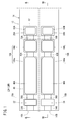
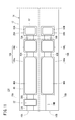
- a gas sensor according to the first embodiment (hereinafter referred to as a first gas sensor 10A) has a sensor element 12 as shown in FIGS. 1 to 3.
- the sensor element 12 has a structure 14 made of an oxygen ion conductive solid electrolyte, and a first sensor cell 15A and a second sensor cell 15B formed in the structure 14.
- the first sensor cells 15A and the second sensor cells 15B are arranged in the horizontal direction in the structure 14 It is provided.
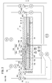
- the first sensor cell 15A is formed in the structure 14, and is formed in the first gas introduction port 16A into which the gas to be measured is introduced, and in the structure 14, and is formed in the first gas introduction port 16A. It has a first oxygen concentration adjustment chamber 18A in communication, and a first measurement chamber 20A formed in the structure 14 and in communication with the first oxygen concentration adjustment chamber 18A.
- the first oxygen concentration adjustment chamber 18A has a first main adjustment chamber 18Aa in communication with the first gas inlet 16A and a first sub adjustment chamber 18Ab in communication with the first main adjustment chamber 18Aa.
- the first measurement chamber 20A communicates with the first auxiliary adjustment chamber 18Ab.
- the first sensor cell 15A is provided between the first gas inlet 16A and the first main adjustment chamber 18Aa in the structure 14 and has a preliminary adjustment chamber 22 communicated with the first gas inlet 16A. .
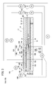
- the second sensor cell 15B is formed in the structural body 14 and is formed in the structural body 14 with the second gas inlet 16B into which the gas to be measured is introduced. It has a second oxygen concentration adjustment chamber 18B in communication with 16B, and a second measurement chamber 20B formed in the structure 14 and in communication with the second oxygen concentration adjustment chamber 18B.
- the second oxygen concentration adjustment chamber 18B has a second main adjustment chamber 18Ba in communication with the second gas inlet 16B and a second sub adjustment chamber 18Bb in communication with the second main adjustment chamber 18Ba.
- the second measurement chamber 20B is in communication with the second auxiliary adjustment chamber 18Bb.
- the second sensor cell 15B is provided between the second gas introduction port 16B and the second main adjustment chamber 18Ba in the structural body 14, and the diffusion resistance adjustment chamber 24 (in communication with the second gas introduction port 16B) A first chamber of the second sensor cell 15B).
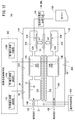
- the structure 14 includes a first substrate layer 26 a, a second substrate layer 26 b, a third substrate layer 26 c, a first solid electrolyte layer 28, and a spacer.
- Six layers of the layer 30 and the second solid electrolyte layer 32 are stacked in this order from the lower side in the drawing view.
- Each layer is composed of an oxygen ion conductive solid electrolyte layer such as zirconia (ZrO 2 ).
- the first sensor cell 15A is located on the tip end side of the sensor element 12, and between the lower surface of the second solid electrolyte layer 32 and the upper surface of the first solid electrolyte layer 28 is a first gas.
- the inlet 16A, the first diffusion control unit 34A, the preliminary adjustment chamber 22, the second diffusion control unit 36A, the first oxygen concentration adjustment chamber 18A, the third diffusion control unit 38A, and the first measurement chamber 20A Is equipped.
- a fourth diffusion control unit 40A is provided between the first main adjustment chamber 18Aa constituting the first oxygen concentration adjustment chamber 18A and the first sub adjustment chamber 18Ab.
- the first gas inlet 16A, the first diffusion control unit 34A, the preliminary adjustment chamber 22, the second diffusion control unit 36A, the first main adjustment chamber 18Aa, the fourth diffusion control unit 40A, and the first auxiliary The adjustment chamber 18Ab, the third diffusion control unit 38A, and the first measurement chamber 20A are formed adjacent to each other in such a manner as to communicate in this order.
- a portion from the first gas inlet 16A to the first measurement chamber 20A is also referred to as a first gas circulation unit.
- the first gas inlet 16A, the preliminary adjustment chamber 22, the first main adjustment chamber 18Aa, the first auxiliary adjustment chamber 18Ab, and the first measurement chamber 20A are provided in a mode in which the spacer layer 30 is hollowed out. It is a space.
- the preliminary adjustment chamber 22, the first main adjustment chamber 18Aa, the first sub-adjustment chamber 18Ab, and the first measurement chamber 20A are all upper in the lower surface of the second solid electrolyte layer 32 and lower in the first solid. Each side of the upper surface of the electrolyte layer 28 is divided by the side surface of the spacer layer 30.
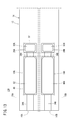
- the second sensor cell 15B As shown in FIG. 3, between the lower surface of the second solid electrolyte layer 32 and the upper surface of the first solid electrolyte layer 28 on the tip end side of the sensor element 12
- the second gas inlet 16B, the first diffusion control unit 34B, the diffusion resistance adjustment chamber 24, the second diffusion control unit 36B, the second oxygen concentration adjustment chamber 18B, the third diffusion control unit 38B, and the second A measuring room 20B is provided.
- a fourth diffusion control unit 40B is provided between the second main adjustment chamber 18Ba constituting the second oxygen concentration adjustment chamber 18B and the second sub adjustment chamber 18Bb.
- the second gas inlet 16B, the first diffusion control unit 34B, the diffusion resistance adjustment chamber 24, the second diffusion control unit 36B, the second main adjustment chamber 18Ba, the fourth diffusion control unit 40B, and the second The sub adjustment chamber 18Bb, the third diffusion control unit 38B, and the second measurement chamber 20B are formed adjacent to each other in such a manner as to communicate in this order.
- a portion from the second gas inlet 16B to the second measurement chamber 20B is also referred to as a second gas circulation unit.
- the second gas inlet 16B, the diffusion resistance adjustment chamber 24, the second main adjustment chamber 18Ba, the second sub adjustment chamber 18Bb, and the second measurement chamber 20B are provided in a mode in which the spacer layer 30 is hollowed out. It is an internal space.
- the diffusion resistance adjusting chamber 24, the second main adjusting chamber 18 Ba, the second sub adjusting chamber 18 Bb, and the second measuring chamber 20 B are all upper in the lower surface of the second solid electrolyte layer 32 and lower in the first Each side of the upper surface of the solid electrolyte layer 28 is divided by the side surface of the spacer layer 30.
- each of the first diffusion rate limiting portion (34A, 34B), the third diffusion rate limiting portion (38A, 38B) and the fourth diffusion rate limiting portion (40A, 40B) is two. It is provided as an elongated slit (the opening has a longitudinal direction in the direction perpendicular to the drawing).
- the second diffusion limiting portion (36A, 36B) is provided as a single long slit (the opening has a longitudinal direction in the direction perpendicular to the drawing).
- first sensor cell 15A and the first sensor cell 15A are positioned between the upper surface of the third substrate layer 26c and the lower surface of the spacer layer 30 and farther from the tip side than the first gas circulation portion and the second gas circulation portion, respectively.
- a reference gas introduction space 41 common to the second sensor cell 15B is provided.
- the reference gas introduction space 41 is an internal space partitioned at the top by the lower surface of the spacer layer 30, at the lower by the upper surface of the third substrate layer 26c, and at the side by the side of the first solid electrolyte layer 28.
- oxygen or air is introduced into the reference gas introduction space 41 as a reference gas.
- the first gas inlet 16A and the second gas inlet 16B are portions that are open to the external space, and the first sensor cell 15A is connected to the external space through the first gas inlet 16A and the second gas inlet 16B. A gas to be measured is taken into the inner and second sensor cells 15B.
- the first diffusion limiting portion 34A of the first sensor cell 15A is a portion that applies a predetermined diffusion resistance to the gas to be measured introduced from the first gas inlet 16A to the preparatory adjustment chamber 22.
- the preliminary adjustment chamber 22 will be described later.
- the first diffusion control part 34B of the second sensor cell 15B is a part that applies a predetermined diffusion resistance to the measurement gas introduced into the diffusion resistance adjustment chamber 24 from the second gas inlet 16B.
- the second diffusion rate control part 36A of the first sensor cell 15A is a part that applies a predetermined diffusion resistance to the measurement gas introduced from the preparatory adjustment chamber 22 to the first main adjustment chamber 18Aa.
- the second diffusion rate control unit 36B of the second sensor cell 15B is a part that applies a predetermined diffusion resistance to the measurement gas introduced from the diffusion resistance adjustment chamber 24 to the second main adjustment chamber 18Ba.
- the first main adjustment chamber 18Aa is provided as a space for adjusting the partial pressure of oxygen in the measurement gas introduced from the first gas inlet 16A.
- the oxygen partial pressure is adjusted by the operation of a first main pump cell 42A described later.
- the second main adjustment chamber 18Ba is provided as a space for adjusting the partial pressure of oxygen in the measurement gas introduced from the second gas inlet 16B.
- the oxygen partial pressure is adjusted by the operation of a second main pump cell 42B described later.
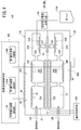
- the first main pump cell 42A includes a first main inner pump electrode 44A, an outer pump electrode 46 common to the first sensor cell 15A and the second sensor cell 15B, and an oxygen ion conductive solid electrolyte sandwiched between these electrodes. It is a 1st electrochemical pump cell (main electrochemical pumping cell) comprised.
- the first main inner pump electrode 44A is provided on substantially the entire surface of the upper surface of the first solid electrolyte layer 28 partitioning the first main adjustment chamber 18Aa, the lower surface of the second solid electrolyte layer 32, and the side surface of the spacer layer 30. It is done.
- the common outer pump electrode 46 extends from the region corresponding to the first main inner pump electrode 44A to the region corresponding to the second main inner pump electrode 44B (the second sensor cell 15B) on the upper surface of the second solid electrolyte layer 32 It is provided in the form exposed to space.
- the first main pump cell 42A applies the first pump voltage Vp1 from the first variable power supply 48A for the first sensor cell provided outside the sensor element 12 to share the common outer pump electrode 46 and the first main inner pump electrode 44A.
- the oxygen in the first main adjustment chamber 18Aa can be pumped out to the outside space, or the oxygen in the outside space can be pumped into the first main adjustment chamber 18Aa by flowing the first pump current Ip1 between them. ing.
- the first sensor cell 15A has a first oxygen partial pressure detection sensor cell 50A which is an electrochemical sensor cell.
- the first oxygen partial pressure detection sensor cell 50A is sandwiched between the first main inner pump electrode 44A, a common reference electrode 52 sandwiched between the upper surface of the third substrate layer 26c and the first solid electrolyte layer 28, and these electrodes. And an oxygen ion conductive solid electrolyte.
- the common reference electrode 52 is made of the same porous cermet as the common outer pump electrode 46 and the like, and is a substantially rectangular electrode in plan view. Further, around the common reference electrode 52, a common reference gas introduction layer 54 made of porous alumina and connected to the common reference gas introduction space 41 is provided.
- the first oxygen partial pressure detection sensor cell 50A has the first main inner pump electrode 44A and the reference electrode 52 due to the difference in oxygen concentration between the atmosphere in the first main adjustment chamber 18Aa and the reference gas in the reference gas introduction space 41. In the meantime, a first electromotive force V1 is generated.
- the first electromotive force V1 generated in the first oxygen partial pressure detection sensor cell 50A changes in accordance with the oxygen partial pressure of the atmosphere present in the first main adjustment chamber 18Aa.
- the first sensor cell 15A performs feedback control of the first variable power supply 48A of the first main pump cell 42A by the first electromotive force V1.
- the first pump voltage Vp1 applied to the first main pump cell 42A by the first variable power source 48A can be controlled according to the oxygen partial pressure of the atmosphere of the first main adjustment chamber 18Aa.
- the fourth diffusion limiting portion 40A applies a predetermined diffusion resistance to the gas to be measured whose oxygen concentration (oxygen partial pressure) is controlled by the operation of the first main pump cell 42A in the first main adjustment chamber 18Aa, It is a site
- the first sub-adjustment chamber 18Ab After the oxygen concentration (oxygen partial pressure) is adjusted in advance in the first main adjustment chamber 18Aa, the first sub-adjustment chamber 18Ab will be described later with respect to the gas to be measured introduced through the fourth diffusion control unit 40A. (1) It is provided as a space for adjusting the partial pressure of oxygen by the auxiliary pump cell 56A. As a result, the oxygen concentration in the first auxiliary adjustment chamber 18Ab can be kept constant with high accuracy, so that the first sensor cell 15A can perform NOx concentration measurement with high accuracy.
- the first auxiliary pump cell 56A is an electrochemical pump cell, and is common to the first auxiliary pump electrode 58A provided on substantially the entire lower surface of the second solid electrolyte layer 32 facing the first auxiliary adjustment chamber 18Ab.
- An electrode 46 and a second solid electrolyte layer 32 are provided.
- the first auxiliary pump electrode 58A is also formed using a material having a reduced ability to reduce NOx components in the measurement gas, as in the first main inner pump electrode 44A.
- the first auxiliary pump cell 56A applies the desired second voltage Vp2 between the first auxiliary pump electrode 58A and the outer pump electrode 46 to transfer oxygen in the atmosphere in the first auxiliary adjustment chamber 18Ab to the external space. It is possible to pump or to pump into the first auxiliary control chamber 18Ab from the outside space.
- the first auxiliary pump electrode 58A, the reference electrode 52, the second solid electrolyte layer 32, the spacer layer 30, and the first The solid electrolyte layer 28 and the electrochemical sensor cell, that is, the second oxygen partial pressure detection sensor cell 50B for controlling the first auxiliary pump are configured.
- the first auxiliary pump cell 56A performs pumping with the second variable power supply 48B that is voltage-controlled based on the second electromotive force V2 detected by the second oxygen partial pressure detection sensor cell 50B.
- the oxygen partial pressure in the atmosphere in the first auxiliary adjustment chamber 18Ab is controlled to a low partial pressure that does not substantially affect the measurement of NOx.
- the second pump current value Ip2 of the first auxiliary pump cell 56A is used to control the second electromotive force V2 of the second oxygen partial pressure detection sensor cell 50B.
- the second pump current Ip2 is input as a control signal to the second oxygen partial pressure detection sensor cell 50B, and the second electromotive force V2 is controlled, whereby the first auxiliary current is transmitted through the fourth diffusion control unit 40A.
- the gradient of the oxygen partial pressure in the measurement gas introduced into the adjustment chamber 18Ab is controlled to be constant at all times.
- the first variable power supply 48A of the first main pump cell 42A is feedback-controlled so that the second pump current value Ip2 becomes constant, the accuracy of oxygen partial pressure control in the first sub adjustment chamber 18Ab is further improved. .
- the oxygen concentration in the first auxiliary adjustment chamber 18Ab is accurately adjusted to a predetermined value of each condition by the actions of the first main pump cell 42A and the first auxiliary pump cell 56A. Will be kept.
- the third diffusion rate control unit 38A applies a predetermined diffusion resistance to the gas to be measured whose oxygen concentration (oxygen partial pressure) is controlled by the operation of the first auxiliary pump cell 56A in the first auxiliary adjustment chamber 18Ab, It is a part which leads gas to the 1st measurement room 20A.
- the first measurement pump cell 60A is an electrochemical device including the first measurement electrode 62A, the common outer pump electrode 46, the second solid electrolyte layer 32, the spacer layer 30, and the first solid electrolyte layer 28. It is a pump cell.
- the first measurement electrode 62A is provided directly on, for example, the upper surface of the first solid electrolyte layer 28 in the first measurement chamber 20A, and has a reduction ability with respect to the NOx component in the measurement gas compared to the first main inner pump electrode 44A. It is a porous cermet electrode composed of an enhanced material.
- the first measurement electrode 62A also functions as a NOx reduction catalyst that reduces NOx present in the atmosphere on the first measurement electrode 62A.
- the first measurement pump cell 60A pumps out oxygen generated by the decomposition of nitrogen oxides in the atmosphere (in the first measurement chamber 20A) around the first measurement electrode 62A, and the amount of generation thereof is the third pump current value Ip3. That is, it can be detected as the sensor output (first measurement pump current value Ip3) of the first sensor cell 15A.
- a third oxygen partial pressure detection sensor cell 50C for measuring pump control is configured.
- the third variable power supply 48C is controlled based on the third electromotive force V3 detected by the third oxygen partial pressure detection sensor cell 50C.
- the measurement gas introduced into the first auxiliary adjustment chamber 18Ab reaches the first measurement electrode 62A in the first measurement chamber 20A through the third diffusion control unit 38A under the control of the oxygen partial pressure.
- the nitrogen oxides in the gas to be measured around the first measurement electrode 62A are reduced to generate oxygen.
- the generated oxygen is pumped by the first measurement pump cell 60A.
- the third voltage Vp3 of the third variable power supply 48C is controlled such that the third electromotive force V3 detected by the third oxygen partial pressure detection sensor cell 50C becomes constant.
- the amount of oxygen generated around the first measurement electrode 62A is proportional to the concentration of nitrogen oxides in the measurement gas. Therefore, the nitrogen oxide concentration in the gas to be measured can be calculated using the first measurement pump current value Ip3 of the first measurement pump cell 60A. That is, the first measurement pump cell 60A measures the concentration of the specific component (NO) in the first measurement chamber 20A.
- the first heater 72A is formed in a mode in which the first sensor cell 15A is vertically sandwiched between the second substrate layer 26b and the third substrate layer 26c.
- the first heater 72A generates heat by being supplied with power from the outside through a heater electrode (not shown) provided on the lower surface of the first substrate layer 26a.
- the heat generation of the first heater 72A enhances the oxygen ion conductivity of the solid electrolyte constituting the first sensor cell 15A.
- the first heater 72A is embedded throughout the preliminary adjustment chamber 22, the oxygen concentration adjustment chamber 18, and the first measurement chamber 20A, and heats and maintains a predetermined place of the first sensor cell 15A to a predetermined temperature. It can be done.
- a first heater insulating layer 74A made of alumina or the like is formed on the upper and lower surfaces of the first heater 72A for the purpose of obtaining electrical insulation between the second substrate layer 26b and the third substrate layer 26c.
- the preliminary adjustment chamber 22 functions as a space for adjusting the oxygen partial pressure in the measurement gas introduced from the first gas inlet 16A.
- the oxygen partial pressure is adjusted by the operation of a preliminary pump cell 80 described later.
- the preliminary pump cell 80 includes a preliminary pump electrode 82 provided on substantially the entire lower surface of the second solid electrolyte layer 32 facing the preliminary adjustment chamber 22, an outer pump electrode 46, and a second solid electrolyte layer 32. , Is a preliminary electrochemical pump cell.
- the spare pump electrode 82 is also formed using a material having a reduced ability to reduce NOx components in the gas to be measured, as with the first main inner pump electrode 44A.
- the preliminary pump cell 80 pumps the oxygen in the atmosphere in the preconditioning chamber 22 to the external space by applying a desired preliminary voltage Vp 0 between the preliminary pump electrode 82 and the outer pump electrode 46, or from the external space It is possible to pump into the preparatory chamber 22.
- the first sensor cell 15A has a preliminary oxygen partial pressure detection sensor cell 84 for preliminary pump control in order to control the partial pressure of oxygen in the atmosphere in the preliminary adjustment chamber 22.
- the preliminary oxygen partial pressure detection sensor cell 84 has a preliminary pump electrode 82, a reference electrode 52, a second solid electrolyte layer 32, a spacer layer 30, and a first solid electrolyte layer 28.
- the spare pump cell 80 pumps with the spare variable power supply 86 that is voltage-controlled based on the spare electromotive force V0 detected by the spare oxygen partial pressure detection sensor cell 84. Thereby, the partial pressure of oxygen in the atmosphere in the preconditioning chamber 22 is controlled to a low partial pressure which has substantially no influence on the measurement of NOx.
- the preliminary pump current value Ip 0 is used to control the electromotive force of the preliminary oxygen partial pressure detection sensor cell 84.
- the preliminary pump current Ip0 is input as a control signal to the preliminary oxygen partial pressure detection sensor cell 84, and the preliminary electromotive force V0 is controlled, whereby the first diffusion control unit 34A enters the preliminary adjustment chamber 22.
- the gradient of oxygen partial pressure in the gas to be measured to be introduced is controlled to be constant at all times.
- the preliminary adjustment chamber 22 also functions as a buffer space. That is, it is possible to cancel out the concentration fluctuation of the measurement gas caused by the pressure fluctuation of the measurement gas in the external space (the pulsation of the exhaust pressure if the measurement gas is the exhaust gas of a car).
- the second sensor cell 15B includes the second main pump cell 42B, the second auxiliary pump cell 56B, the fourth oxygen partial pressure detection sensor cell 50D, the fifth oxygen partial pressure detection sensor cell 50E, and the sixth oxygen partial pressure It has a detection sensor cell 50F.
- the second main pump cell 42B includes a second main inner pump electrode 44B, a common outer pump electrode 46, and an oxygen ion conductive solid electrolyte sandwiched between these electrodes. And a second electrochemical pump cell (main electrochemical pumping cell).
- the fourth pump voltage Vp4 is applied by the fourth variable power supply 48D for the second sensor cell, and the fourth pump current Ip4 is caused to flow between the common outer pump electrode 46 and the second main inner pump electrode 44B.
- the oxygen in the main adjustment chamber 18Ba can be pumped out to the outside space, or the oxygen in the outside space can be pumped into the second main adjustment chamber 18Ba.
- the second auxiliary pump cell 56B is an electrochemical pump cell, and is provided on substantially the entire lower surface of the second solid electrolyte layer 32 facing the second auxiliary adjustment chamber 18Bb.
- a secondary auxiliary pump electrode 58 B, a common outer pump electrode 46 and a second solid electrolyte layer 32 are provided.
- the second auxiliary pump cell 56B applies the desired fifth voltage Vp5 between the second auxiliary pump electrode 58B and the outer pump electrode 46 to transfer oxygen in the atmosphere in the second auxiliary adjustment chamber 18Bb to the external space. It is possible to pump out or to pump into the second auxiliary control chamber 18Bb from the outside space.
- the fourth oxygen partial pressure detection sensor cell 50D is commonly held between the second main inner pump electrode 44B, the upper surface of the third substrate layer 26c, and the first solid electrolyte layer 28.
- the fourth oxygen partial pressure detection sensor cell 50D has the second main inner pump electrode 44B and the reference electrode due to the difference in oxygen concentration between the atmosphere in the second main adjustment chamber 18Ba and the reference gas in the reference gas introduction space 41.
- a fourth electromotive force V4 is generated between the voltage 52 and the voltage 52.
- the fourth electromotive force V4 generated in the fourth oxygen partial pressure detection sensor cell 50D changes in accordance with the oxygen partial pressure of the atmosphere present in the second main adjustment chamber 18Ba.
- the second sensor cell 15B performs feedback control of the fourth variable power supply 48D of the second main pump cell 42B by the fourth electromotive force V4.
- the fourth pump voltage Vp4 applied to the second main pump cell 42B by the fourth variable power supply 48D can be controlled according to the oxygen partial pressure of the atmosphere of the second main adjustment chamber 18Ba.
- the second auxiliary pump electrode 58B in order to control the oxygen partial pressure in the atmosphere in the second auxiliary adjustment chamber 18Bb, the second auxiliary pump electrode 58B, the reference electrode 52, the second solid electrolyte layer 32, the spacer layer 30, and the first An electrochemical sensor cell, that is, a fifth oxygen partial pressure detection sensor cell 50E for controlling the second auxiliary pump is constituted by the solid electrolyte layer 28.
- the second auxiliary pump cell 56B performs pumping with the fifth variable power supply 48E that is voltage-controlled based on the fifth electromotive force V5 detected by the fifth oxygen partial pressure detection sensor cell 50E.
- the oxygen partial pressure in the atmosphere in the second auxiliary adjustment chamber 18Bb is controlled to a low partial pressure that does not substantially affect the measurement of NOx.
- the fifth pump current value Ip5 of the second auxiliary pump cell 56B is used to control the fifth electromotive force V5 of the fifth oxygen partial pressure detection sensor cell 50E. That is, the gradient of the oxygen partial pressure in the measurement gas introduced into the second auxiliary adjustment chamber 18Bb is controlled to be constant at all times.
- a sensor cell that is, a sixth oxygen partial pressure detection sensor cell 50F for measuring pump control is configured.
- the sixth variable power supply 48F is controlled based on the sixth electromotive force V6 detected by the sixth oxygen partial pressure detection sensor cell 50F.
- the measurement gas introduced into the second auxiliary adjustment chamber 18Bb reaches the second measurement electrode 62B in the second measurement chamber 20B through the third diffusion control unit 38B under the control of the oxygen partial pressure.
- the nitrogen oxides in the gas to be measured around the second measurement electrode 62B are reduced to generate oxygen.
- the generated oxygen is pumped by the second measurement pump cell 60B.
- the sixth voltage Vp6 of the sixth variable power supply 48F is controlled such that the sixth electromotive force V6 detected by the sixth oxygen partial pressure detection sensor cell 50F becomes constant.
- the amount of oxygen generated around the second measurement electrode 62B is proportional to the concentration of nitrogen oxides in the measurement gas. Therefore, the nitrogen oxide concentration in the gas to be measured can be calculated using the second measurement pump current value Ip6 of the second measurement pump cell 60B. That is, the second measurement pump cell 60B measures the concentration of the specific component (NO) in the second measurement chamber 20B.
- the second sensor cell 15B has an electrochemical oxygen detection cell 70.
- the oxygen detection cell 70 includes a second solid electrolyte layer 32, a spacer layer 30, a first solid electrolyte layer 28, a third substrate layer 26 c, an outer pump electrode 46, and a reference electrode 52.
- the partial pressure of oxygen in the gas to be measured outside the sensor element 12 can be detected by the electromotive force Vr obtained by the oxygen detection cell 70.
- the second heater 72B similar to the first heater 72A described above is formed in a mode in which the second sensor cell 15B is vertically sandwiched by the second substrate layer 26b and the third substrate layer 26c.
- the second heater 72B is embedded throughout the diffusion resistance adjustment chamber 24, the second oxygen concentration adjustment chamber 18B, and the first measurement chamber 20A, and heats a predetermined location of the second sensor cell 15B to a predetermined temperature, It can be kept warm.
- a second heater insulating layer 74B made of alumina or the like is also formed on the upper and lower surfaces of the second heater 72B in order to obtain electrical insulation between the second substrate layer 26b and the third substrate layer 26c.
- the first heater 72A and the second heater 72B may be configured by one common heater, and in this case, the first heater insulating layer 74A and the second heater insulating layer 74B are also common.
- the diffusion resistance adjusting chamber 24 also functions as a buffer space. That is, it is possible to cancel out the concentration fluctuation of the measurement gas caused by the pressure fluctuation of the measurement gas in the external space (the pulsation of the exhaust pressure if the measurement gas is the exhaust gas of a car).
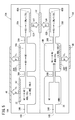
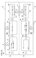
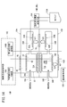
- the first gas sensor 10A includes a temperature control unit 100, an oxygen concentration control unit 102, and a target component concentration acquisition unit 104.
- the temperature control means 100 controls energization of the first heater 72A and the second heater 72B of the sensor element 12 to control the temperatures of the first sensor cell 15A and the second sensor cell 15B.
- the oxygen concentration control means 102 controls the oxygen concentration in the first oxygen concentration adjustment chamber 18A of the first sensor cell 15A, and the oxygen in the second oxygen concentration adjustment chamber 18B of the second sensor cell 15B.
- the target component concentration acquisition means 104 includes a first measurement pump current value Ip3 flowing to the first measurement pump cell 60A of the first sensor cell 15A and a second measurement pump current value Ip6 flowing to the second measurement pump cell 60B of the second sensor cell 15B.
- first target component (NO) and the second target component (NH 3 ) based on the difference (change amount ⁇ Ip) the second measurement pump current value Ip6 (total concentration), and the first map 110A described later.
- the temperature control unit 100, the oxygen concentration control unit 102, and the target component concentration acquisition unit 104 are constituted by, for example, one or more CPUs (central processing units) and one or more electronic circuits having a storage device and the like.
- the electronic circuit is also a software function unit in which a predetermined function is realized by the CPU executing a program stored in, for example, a storage device.
- an integrated circuit such as a field-programmable gate array (FPGA) may be formed by connecting a plurality of electronic circuits in accordance with the function.
- FPGA field-programmable gate array
- the NOx sensor with a conventional in-line two-chamber structure converts all of the target components of NO and NH 3 into NO in the oxygen concentration adjustment chamber, and then introduces it into the measurement chamber to measure the total amount of these two components. It was That is, it was not possible to measure the concentration of each of the two target components, that is, the concentrations of NO and NH 3 .
- the first gas sensor 10A is first sensor cell 15A described above, the second sensor cell 15B, by including a temperature control means 100, the oxygen concentration control means 102 and the target component concentration acquiring unit 104, NO and NH 3 Of each concentration can be obtained.
- the temperature control means 100 sets the first heater 72A and the second heater 72B based on the conditions of the sensor temperature set in advance and the measurement value from the temperature sensor (not shown) that measures the temperature of the sensor element 12. By feedback control, the temperature of the sensor element 12 is adjusted to the temperature according to the above conditions.
- the first oxygen concentration control unit 106A of the oxygen concentration control means 102 generates the conditions of the oxygen concentration in the first oxygen concentration adjustment chamber 18A set in advance and the first oxygen partial pressure detection sensor cell 50A (see FIG. 2).
- the oxygen concentration in the first oxygen concentration adjusting chamber 18A is adjusted to a concentration according to the above condition by feedback control of the first variable power supply 48A based on the one electromotive force V1.
- the second oxygen concentration control unit 106B of the oxygen concentration control means 102 generates the condition of the oxygen concentration in the second oxygen concentration adjustment chamber 18B set in advance and the fourth oxygen partial pressure detection sensor cell 50D (see FIG. 3).
- the oxygen concentration in the second oxygen concentration adjustment chamber 18B is adjusted to a concentration according to the above conditions by feedback control of the fourth variable power supply 48D based on the four electromotive forces V4.
- the first gas sensor 10A uses the oxygen concentration control means 102 or the temperature control means 100, or the oxygen concentration control means 102 and the temperature control means 100 to generate NO in the first oxygen concentration adjustment chamber 18A and the second oxygen concentration adjustment chamber 18B. Control to convert NH 3 to NO at a rate that can be used for NH 3 measurement without decomposing it.
- the preliminary oxygen concentration control unit 108 of the oxygen concentration control means 102 sets the preliminary variable power supply based on the preset oxygen concentration condition and the preliminary electromotive force V0 generated in the preliminary oxygen partial pressure detection sensor cell 84 (see FIG. 2).
- the oxygen concentration in the preconditioning chamber 22 is adjusted to the concentration according to the conditions.
- This preliminary oxygen concentration control unit 108 without decomposing NO preconditioning chamber 22 in the first sensor cell 15A, NH 3 is converted to NO in a ratio that can be used for NH 3 measurement.
- NH 3 introduced into the preconditioning chamber 22 through the first gas inlet 16A undergoes an oxidation reaction of NH 3 ⁇ NO in the preconditioning chamber 22, All NH 3 introduced through the 1 gas inlet 16A is converted to NO. Accordingly, NH 3 is passed through the diffusion coefficient 2.2 cm 2 / sec of the NH 3 to the first diffusion control part 34A, the diffusion coefficient of the second diffusion rate-determining section 36A after the NO in from preconditioning chamber 22 to the back 1. It moves to the first measurement chamber 20A at a speed of 8 cm 2 / sec.
- the oxygen concentration control means 102 since it is controlled so as to convert all NH 3 NO, NH 3 flowing into the second oxygen concentration adjusting chamber 18B In the second oxygen concentration adjustment chamber 18B, an oxidation reaction of NH 3 ⁇ NO occurs, and all NH 3 in the second oxygen concentration adjustment chamber 18B is converted to NO.
- NH 3 introduced through the second gas inlet 16 B passes through the first diffusion control part 34 B and the second diffusion control part 36 B at a rate of a diffusion coefficient of 2.2 cm 2 / sec of NH 3 , and the second oxygen After being converted into NO in the concentration adjustment chamber 18B, it passes through the third diffusion-controlled portion 38B at a speed of a diffusion coefficient of NO of 1.8 cm 2 / sec, and moves into the adjacent second measurement chamber 20B.
- the second sensor cell 15B, where the oxidation reaction of NH 3 occurs is a second oxygen concentration adjusting chamber 18B.
- the second diffusion control part (36A, 36B) or through NO the of differences through with NH 3, the first measurement chamber 20A and the second measurement chamber This corresponds to the difference in the amount of NO flowing into 20B.
- the second measurement pump current value Ip6 of the second measurement pump cell 60B corresponds to the total value of the NH 3 concentration and the NO concentration in the measurement gas.
- the amount of change ⁇ Ip between the first measurement pump current value Ip3 and the second measurement pump current value Ip6 changes according to the concentration of NH 3 in the gas to be measured. Therefore, obtaining a second measured pump current flowing through the second measuring pumping cell 60B Ip6 (total concentration of NO and NH 3), each concentration of NO and NH 3 from the above-mentioned amount of change Delta] Ip (concentration of NH 3) can do.
- the target component concentration acquisition means 104 (see FIG. 4), the amount of change ⁇ Ip between the first measurement pump current value Ip3 and the second measurement pump current value Ip6, the second measurement pump current value Ip6, for example, the first map Each concentration of NO and NH 3 is obtained based on 110A (see FIG. 6).
- the second measurement pump current value Ip6 ( ⁇ A) is set on the horizontal axis, and the first measurement pump current value Ip3 and the first measurement pump current value Ip3 are on the vertical axis.
- FIG. 6 representatively, the first plot line P1 and the second plot group P2 of the first characteristic line L1 and the second characteristic line L2 and the NO concentration conversion value of the variation ⁇ Ip in the 100 ppm system, 50 ppm system and 25 ppm system. And a third plot group P3.
- the first characteristic line L1 changes the concentration conversion value of NH 3 to 0 ppm, 25 ppm, 50 ppm, 75 ppm and 100 ppm when the concentration conversion value of NO is 0 ppm, that is, when NO is contained in the measurement gas. It shows the characteristics when it is made to
- the second characteristic line L 2 sets the concentration conversion value of NO to 0 ppm, 25 ppm, 50 ppm, 75 ppm and 100 ppm. It shows the characteristics when changed.
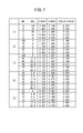
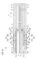
- the contents of the first column [1] correspond to the first characteristic line L1 of FIG. 6, and the contents of the second column [2] correspond to the second characteristic line L2 of FIG.
- the comparison of [1] and [2] shows that NH 3 has a sensitivity 1.14 times that of NO. This occurs based on the difference in diffusion coefficient between NH 3 and NO, and is determined by the temperature of the sensor element 12 and the oxygen concentration in the internal space.
- the contents of the third column [3] correspond to the first plot group P1 of FIG. 6, and the contents of the fourth column [4] correspond to the second plot group P2 of FIG.
- the contents of the fifth column [5] correspond to the third plot group P3 of FIG.
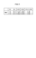
- the total concentration (NO conversion value) based on the second measurement pump current value Ip6 That is, one of 100 ppm system, 50 ppm system and 25 ppm system is determined, the NH 3 concentration is obtained based on the variation ⁇ Ip, and the NH 3 concentration is subtracted from the total concentration to obtain the NO concentration.
- the second measurement pump current value Ip6 is 0.537 ( ⁇ A)
- the total concentration is 25 ppm system.
- the change amount ⁇ Ip was 0.041 ( ⁇ A)
- the nearest change amount ⁇ Ip is specified on the map to calculate the total concentration, and for example, the NH 3 concentration is obtained by known approximation calculation. Good. Then, the NH 3 concentration may be subtracted from the calculated total concentration to obtain the NO concentration.
- NH 3, NO each concentration and Delta] Ip and to calculate the concentration of NH 3 which is a second target component based on the correlation equation between Ip6, by subtracting the concentration of the second target component from the total concentration, first The concentration of NO which is the target component may be calculated.
- the sensor element 12 described above is manufactured, metal parts are assembled into a sensor shape, attached to the Dell gas measuring apparatus, and the sensor element 12 is assembled by the first heater 72A and the second heater 72B built in the sensor element 12. Heat to approximately 800 ° C.
- the electromotive force between the first measurement electrode 62A and the reference electrode 52 of the first measurement pump cell 60A in the first sensor cell 15A, and the second measurement electrode 62B of the second measurement pump cell 60B in the second sensor cell 15B The voltage applied between the first measurement electrode 62A and the outer pump electrode 46 and the voltage applied between the second measurement electrode 62B and the outer pump electrode 46 are feedback controlled so that the electromotive force between the reference electrodes 52 is 400 mV. .
- the voltage applied between the spare pump electrode 82 and the outer pump electrode 46 is feedback-controlled so that the electromotive force between the spare pump electrode 82 of the spare pump cell 80 and the reference electrode 52 in the first sensor cell 15A becomes 230 mV.
- the relationship between the concentration of each NO and NH 3 , the first measurement pump current value Ip 3 and the second measurement pump current Ip 6, and the difference (change amount ⁇ Ip) between the first measurement pump current Ip 3 and the second measurement pump current Ip 6 is shown in FIG.
- the second plot group P2 is shown in the fourth column [4] of Table 1 in FIG.
- the sensor element 12 having the structure 14 made of at least the oxygen ion conductive solid electrolyte, and the first sensor cell 15A and the second sensor cell 15B formed in the structure 14; It has temperature control means 100 for controlling the temperature of the sensor element 12, oxygen concentration control means 102, and target component concentration acquisition means 104.
- the first sensor cell 15A has a first gas inlet 16A, a first diffusion control unit 34A, a preliminary adjustment chamber 22, a second diffusion control unit 36A, a first oxygen concentration adjustment chamber 18A, and a third sensor cell 15A in the gas introduction direction.
- a diffusion control unit 38A and a first measurement chamber 20A are provided.
- the second sensor cell 15B has a second gas introduction port 16B, a first diffusion control unit 34B, a diffusion resistance adjustment chamber 24, a second diffusion control unit 36B, a second oxygen concentration adjustment chamber 18B, and a second sensor cell 15B in the gas introduction direction.
- a diffusion control unit 38B and a second measurement chamber 20B are provided.
- the first measurement chamber 20A of the first sensor cell 15A includes the first measurement pump cell 60A
- the second measurement chamber 20B of the second sensor cell 15B includes the second measurement pump cell 60B.
- the oxygen concentration control means 102 controls the oxygen concentration of the preliminary adjustment chamber 22 of the first sensor cell 15A and the first oxygen concentration adjustment chamber 18A and the oxygen concentration of the second oxygen concentration adjustment chamber 18B of the second sensor cell 15B.
- the target component concentration acquiring unit 104 determines the difference between the first measurement pump current value Ip3 flowing to the first measurement pump cell 60A and the second measurement pump current value Ip6 flowing to the second measurement pump cell 60B (change amount ⁇ Ip).
- the concentration of the second target component (for example, NH 3 ) is acquired based on the second measurement pump current value Ip6 flowing to the second measurement pump cell 60B, and the first target component (for example, NO) and the second target component (for example, The total concentration of NH 3 ) is obtained, and the concentration of the second target component is subtracted from the total concentration to obtain the concentration of the first target component.
- the first gas sensor 10A has such a configuration, even in the atmosphere of a plurality of target components (for example, NO, NH 3 ) coexisting in the presence of unburned components such as exhaust gas and oxygen, the plurality of target components Can be measured accurately over a long period of time.
- a plurality of target components for example, NO, NH 3
- the first gas sensor 10A does not separately perform processing for measuring the concentrations of NO and NH 3 which can not be realized conventionally, and various control devices as hardware, etc., of the control system of the first gas sensor 10A. It can be easily realized simply by changing the software. As a result, it is possible to increase the accuracy with respect to control and failure detection of the NOx purification system. In particular, it is possible to distinguish between NO and NH 3 in the exhaust gas downstream of the SCR system, which contributes to the precise control of the urea injection amount of the SCR system and the detection of deterioration.
- the number of lead wires can be reduced, and for example, mounting on various vehicles can be facilitated.
- the reference electrode 52 disposed in the reference gas introduction space 41 of the first sensor cell 15A and the reference electrode 52 disposed in the reference gas introduction space 41 of the second sensor cell 15B are shared, the number of lead wires can be reduced. This makes it easy to mount on cars and the like.
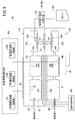
- a gas sensor according to the second embodiment (hereinafter, referred to as a second gas sensor 10B) will be described with reference to FIGS. 9 and 10.
- the second gas sensor 10B includes the second sensor element 12B having the same configuration as the first sensor element 12A of the first gas sensor 10A described above, as shown in FIGS.
- the second target component is NO 2 and the concentration of the first target component (NO) and the concentration of the second target component (NO 2 ) are acquired based on the second map 110B. It is different.
- the second gas sensor 10B is controlled by the oxygen concentration control means 102 or the temperature control means 100, or the oxygen concentration control means 102 and the temperature control means 100, in the first oxygen concentration adjusting chamber 18A and the second oxygen concentration adjusting chamber 18B. Control to convert all NO 2 into NO without decomposing NO of.
- the preliminary oxygen concentration control unit 108 of the oxygen concentration control means 102 sets the preliminary variable power supply based on the preset oxygen concentration condition and the preliminary electromotive force V0 generated in the preliminary oxygen partial pressure detection sensor cell 84 (see FIG. 2). By feedback control of 86, the oxygen concentration in the preconditioning chamber 22 is adjusted to the concentration according to the conditions.
- the preliminary oxygen concentration control unit 108 converts all NO 2 into NO without decomposing NO in the preliminary adjustment chamber 22 in the first sensor cell 15A.
- the NO 2 introduced into the preconditioning chamber 22 through the first gas inlet 16A undergoes a decomposition reaction of NO 2 ⁇ NO in the preconditioning chamber 22. All the NO 2 introduced through the 1 gas inlet 16A is converted to NO.
- the NO 2 introduced through the second gas inlet 16B reaches the second oxygen concentration adjustment chamber 18B.
- the second oxygen concentration adjustment chamber 18B since all the NO 2 is controlled to be converted to NO by the second oxygen concentration control unit 106B of the oxygen concentration control means 102, it flows into the second oxygen concentration adjustment chamber 18B. is the NO 2 takes place decomposition reaction of NO 2 ⁇ NO in the second oxygen concentration adjusting chamber 18B, all NO 2 of the second oxygen concentration adjusting chamber 18B is converted to NO. Therefore, the NO 2 introduced through the second gas inlet 16B passes through the first diffusion control part 34B and the second diffusion control part 36B at the speed of the diffusion coefficient of NO 2 in the second oxygen concentration adjustment chamber 18B. After being converted into NO, it passes through the third diffusion-controlled portion 38B at the speed of the diffusion coefficient of NO, and moves into the adjacent second measurement chamber 20B.
- the place where the decomposition reaction of NO 2 occurs is the preconditioning chamber 22, and in the second sensor cell 15B, the place where the decomposition reaction of NO 2 occurs is the second oxygen concentration adjustment room 18B. Since NO and NO 2 have different diffusion coefficients, the difference between whether NO or NO 2 passes through the second diffusion-controlled portion (36A, 36B) is the first measurement chamber 20A and the second measurement chamber This corresponds to the difference in the amount of NO flowing into 20B. This causes a difference between the first measurement pump current value Ip3 of the first measurement pump cell 60A and the second measurement pump current value Ip6 of the second measurement pump cell 60B. However, the second measurement pump current value Ip6 of the second measurement pump cell 60B corresponds to the total value of the NO 2 concentration and the NO concentration in the measurement gas.
- the amount of change ⁇ Ip between the first measurement pump current value Ip3 and the second measurement pump current value Ip6 is uniquely determined by the concentration of NO 2 in the gas to be measured. Therefore, obtaining a second measured pump current Ip6 (total concentration of NO and NO 2) flowing through the second measuring pumping cell 60B, the respective concentrations of from the above-mentioned amount of change Delta] Ip (concentration of NO 2) NO and NO 2 can do.
- the target component concentration acquiring means 104 the amount of change ⁇ Ip between the first measurement pump current value Ip3 and the second measurement pump current value Ip6, the second measurement pump current value Ip6, and the second map 110B (see FIG. 9). And each concentration of NO 2 and NO 2 is obtained.
- the horizontal axis indicates the second measurement.
- a graph in which the pump current value Ip6 ( ⁇ A) is set, and the variation ⁇ Ip ( ⁇ A) between the first measurement pump current value Ip3 and the second measurement pump current value Ip6 is set on the vertical axis, that is, the second gas sensor 10B Can create graphs and tables corresponding to
- the second gas sensor 10B has such a configuration, even in the atmosphere of a plurality of target components (for example, NO and NO 2 ) coexisting in the presence of unburned components such as exhaust gas and oxygen, the plurality of target components Can be measured accurately over a long period of time.
- a plurality of target components for example, NO and NO 2
- unburned components such as exhaust gas and oxygen
- the second gas sensor 10B does not separately perform processing for measuring each concentration of NO and NO 2 which can not be realized conventionally, and various control devices as hardware, etc., for the control system of the second gas sensor 10B. It can be easily realized simply by changing the software. As a result, it is possible to increase the accuracy with respect to control and failure detection of the NOx purification system. In particular, it is possible to distinguish between NO and NO 2 in exhaust gas downstream of a DOC (Diesel Oxidation Catalyst) catalyst, which contributes to detection of deterioration of the DOC catalyst.
- DOC Diesel Oxidation Catalyst
- FIG. 10C a gas sensor according to the third embodiment (hereinafter referred to as a third gas sensor 10C) will be described with reference to FIGS. 11 and 12.
- FIG. 10C a gas sensor according to the third embodiment
- the third gas sensor 10C is configured such that the diffusion resistance value of the first diffusion-controlled portion 34B of the second sensor cell 15B in the first gas sensor 10A described above (see FIGS. It is an element structure at the time of adjusting substantially equal to the total value of the diffusion resistance value of the 1st gas introduction port 16A of 1 sensor cell 15A, the 1st diffusion control part 34A, the preparatory adjustment room 22, and the 2nd diffusion control part 36A.
- the diffusion resistance adjustment chamber 24 of the second sensor cell 15B and the second diffusion limiting portion 36B are omitted, and a simple structure, for example, when attached to a vehicle An element structure resistant to thermal shock can be provided.
- FIG. 10D a gas sensor according to the fourth embodiment (hereinafter referred to as a fourth gas sensor 10D) will be described with reference to FIGS. 13 and 14.
- FIG. 10D a gas sensor according to the fourth embodiment
- the fourth gas sensor 10D omits the first sensor cell 15A to the fourth diffusion control portion 40A and the first sub adjustment chamber 18Ab of the first gas sensor 10A (see FIGS. 1 and 4) described above. . Instead, the first oxygen concentration adjustment chamber 18A and the first measurement chamber 20A are directly in communication via the third diffusion control unit 38A.
- the diffusion resistance adjustment chamber 24, the second diffusion control unit 36B, the fourth diffusion control unit 40B and the second sub adjustment chamber 18Bb are omitted from the second sensor cell 15B of the first gas sensor 10A (see FIGS. 1 and 4). .
- the second gas inlet 16B and the second oxygen concentration adjustment chamber 18B are directly communicated with each other through the first diffusion control unit 34B, and the second oxygen concentration adjustment chamber 18B and the second measurement chamber 20B are directly connected to the third. Communication is made via the diffusion control portion 38B.
- the oxygen concentration correction means effective for correcting the first measurement pump current Ip3 and the second measurement pump current Ip6 is added to the oxygen concentration control means 102 or the target component concentration acquisition means 104.
- a gas sensor according to the fifth embodiment (hereinafter, referred to as a fifth gas sensor 10E) will be described with reference to FIG.
- the first sensor cell 15A and the second sensor cell 15B need not necessarily be formed on the same plane, and the stacking direction of the solid electrolyte substrate with the heating means (the heater 72 and the heater insulating layer 74) interposed, that is, the thickness direction of the sensor element 12 It may be arranged symmetrically. In this case, the dimension in the width direction of the sensor element 12 can be reduced, which is effective in miniaturizing the sensor element 12.
- the gist of the present invention is the following (a) to (c), and the reaction in which NH 3 or NO 2 is changed to NO can be arbitrarily selected from the range in which fluctuation of sensor output can be obtained.
- a reaction in which NH 3 or NO 2 is changed to NO is intentionally generated before and after a diffusion-limited portion having a predetermined diffusion resistance.
- B According to (a), the concentration of NH 3 or NO 2 is obtained from the fluctuation of the sensor output caused by the difference in diffusion coefficient between NO and NH 3 or NO and NO 2 .
- C further, to obtain a NO concentration by comparing the concentration of NH 3 or NO 2 obtained total concentration of NO and NH 3 obtained by the sensor output itself, or a total concentration of NO and NO 2 by the variation.
- the gas sensor according to the present invention is not limited to the above-described embodiment, and it goes without saying that various configurations can be adopted without departing from the scope of the present invention.
- the first measurement chamber 20A is provided adjacent to the first auxiliary adjustment chamber 18Ab, and the first measurement electrode 62A is disposed in the first measurement chamber 20A.
- the first measurement electrode 62A is disposed in the first auxiliary adjustment chamber 18Ab, and alumina (Al 2 O 3 ) or the like which becomes the third diffusion-controlled portion 38A so as to cover the first measurement electrode 62A.
- the periphery of the first measurement electrode 62A functions as the first measurement chamber 20A.
- the alumina serving as the third diffusion-controlled portion 38B is disposed so as to dispose the second measurement electrode 62B in the second auxiliary adjustment chamber 18Bb and cover the second measurement electrode 62B.
- (Al 2 O 3) film may be formed constituted by ceramic porous body or the like. In this case, the periphery of the second measurement electrode 62B functions as the second measurement chamber 20B.
- the second target component NH 3 or NO 2 is converted to NO at a conversion rate of 100% in the preconditioning chamber 22, but the conversion rate of NH 3 or NO 2 is Is not required to be 100%, and the conversion rate can be arbitrarily set within a range in which a good correlation with the NH 3 concentration or the NO 2 concentration in the gas to be measured can be obtained.
- the driving of the preliminary oxygen concentration control unit 108, in a direction pumping out oxygen from the preconditioning chamber 22 may be in the direction pumped into, by the presence of NH 3 or NO 2 is a second target component, the measuring pumping cell
- the measurement pump currents Ip3 and Ip6, which are outputs, may be changed with good reproducibility.
Abstract
The present invention relates to a gas sensor capable of measuring the concentrations of each of a plurality of target components in a gas being measured. The gas sensor comprises a sensor element (12), an oxygen concentration control means (102), and a target component concentration acquiring means (104). The oxygen concentration control means controls the oxygen concentration in a first chamber and a second chamber of a first sensor cell (15A), and the oxygen concentration in a second chamber of a second sensor cell (15B). The target component concentration acquiring means acquires the concentration of a second target component on the basis of a difference ΔIp between a first pump current value and a second pump current value, and acquires the concentration of a first target component by subtracting the concentration of the second target component from the second pump current value (total concentration).
Description
本発明は、被測定ガス中の複数目的成分の各濃度を測定することが可能なガスセンサに関する。
The present invention relates to a gas sensor capable of measuring each concentration of a plurality of target components in a measurement gas.
従来から、直列2室構造を持ったNOxセンサ(直列2室型NOxセンサ)、及びそれを用いたNOx測定方法(例えば特開2015-200643号公報参照)や、酸化物半導体電極を用いた混成電位型、あるいは抵抗変化型のNO2センサ、あるいはNH3センサが知られている(例えば特開2013-068632号公報及び特開2009-243942号公報参照)。
Conventionally, a NOx sensor (series 2-chamber NOx sensor) having a series 2-chamber structure, a NOx measurement method using the same (for example, see JP-A-2015-200643), and a hybrid using an oxide semiconductor electrode There are known potential-type or resistance-change-type NO 2 sensors or NH 3 sensors (see, for example, JP-A-2013-068632 and JP-A-2009-243942).
また、酸化物半導体電極の混成電位を用いてNH3濃度を測定する方法が知られている。この方法は、NOx濃度を別のセンサで測定し、NO、NO2が存在しない場合は酸化物半導体電極の混成電位をそのまま使用し、NO、NO2が存在する場合は酸化物半導体電極の混成電位に補正を加える方法である(例えば特表2009-511859号公報参照)。
There is also known a method of measuring the NH 3 concentration using the mixed potential of the oxide semiconductor electrode. This method measures the NOx concentration in a different sensor, NO, if NO 2 is not present and used as a mixed potential of the oxide semiconductor electrode, mixture of the oxide semiconductor electrode If NO, NO 2 is present This is a method of correcting the potential (see, for example, Japanese Patent Application Publication No. 2009-511859).
近年、各国のCO2排出量規制が強化される傾向にあり、ディーゼル車の普及率が増えつつある。希薄燃焼を用いるディーゼルエンジンは、CO2排出量が少ない代わりに過剰な酸素を含む排気ガス中のNOx浄化が困難であるという欠点を持つ。そのため、CO2排出量規制の強化と同様に、NOx排出量の規制も強化されつつある。現在は、CO2排出量、すなわち、燃料消費量を損なわずにNOx浄化が行える選択還元型触媒システム(以下、SCRシステムと記す)がNOx浄化の主流を占めている。SCRシステムは、注入した尿素を排気ガスと反応させてアンモニアを生成し、アンモニアとNOxを反応させてN2とO2に分解する。このSCRシステムにおいて、NOx浄化効率を100%に近づけるためには、尿素の注入量を増やす必要があるが、尿素注入量を増やすと未反応のアンモニアが大気に排出されるおそれがある。このため、NOxとアンモニアを区別できるセンサが求められている。
In recent years, restrictions on CO 2 emissions in each country tend to be tightened, and the penetration rate of diesel vehicles is increasing. A diesel engine using lean combustion has the disadvantage that NOx purification in exhaust gas containing excess oxygen is difficult instead of low CO 2 emissions. Therefore, the regulation of NOx emissions is being strengthened as well as the tightening of CO 2 emissions regulations. At present, a selective reduction catalyst system (hereinafter referred to as an SCR system) capable of NOx purification without losing CO 2 emissions, that is, fuel consumption, occupies the mainstream of NOx purification. The SCR system reacts the injected urea with the exhaust gas to produce ammonia, and the ammonia and NOx react to decompose into N 2 and O 2 . In this SCR system, it is necessary to increase the injection amount of urea in order to bring the NOx purification efficiency close to 100%, but when the urea injection amount is increased, unreacted ammonia may be discharged to the atmosphere. Therefore, there is a need for a sensor that can distinguish between NOx and ammonia.
さらには、米国において、酸化触媒(以下、DOC触媒と記す)、ディーゼルパティキュレートフィルタ(以下、DPFと記す)、選択還元型触媒(以下、SCR触媒と記す)の個別故障診断の義務付けに対する準備が進められている。DPF、SCR触媒の故障診断は、既存のPMセンサ、NOxセンサで可能であるが、DOC触媒に対しては有効な故障診断手段が見つかっていない。現在は、200℃以下の低温時のDOC触媒下流に漏れ出す炭化水素(以下、HCと記す)量を測定する方法や、DOC触媒下流に排出されるNOとNO2の比率から故障を判断する方法等が推奨されている。特に、NOとNO2の比率におけるNO2の減少は、HC流出量の増大よりも早期に起こるため、より安全な故障診断方法として期待されている。このため、NOとNO2を区別できるセンサが求められている。
Furthermore, in the United States, preparations are made to oblige for individual failure diagnosis of oxidation catalysts (hereinafter referred to as DOC catalysts), diesel particulate filters (hereinafter referred to as DPF), and selective reduction catalysts (hereinafter referred to as SCR catalysts). It is in progress. Although fault diagnosis of DPF and SCR catalysts is possible with existing PM sensors and NOx sensors, no effective fault diagnosis means has been found for DOC catalysts. Currently, the failure is determined from the method of measuring the amount of hydrocarbon (hereinafter referred to as HC) leaking to the downstream of the DOC catalyst at a low temperature of 200 ° C or less, and the ratio of NO and NO 2 discharged to the downstream of the DOC catalyst. Methods etc. are recommended. In particular, reduction of the NO 2 in the ratio of NO and NO 2, in order to take place earlier than the increase of the HC outflow, are expected to be safer failure diagnosis method. Therefore, a sensor that can distinguish NO and NO 2 are required.
上述した特開2015-200643号公報記載のNOxセンサ及びNOx測定方法は、NO、NO2、NH3をNOに変換し、変換後のNOを分解して発生したO2の量、もしくは濃度を測定する。そのため、NO、NO2、NH3の総量は測定できても各々を区別することができなかった。
The NO x sensor and NO x measuring method described in JP-A-2015-200643 described above convert NO, NO 2 , NH 3 into NO, decompose the converted NO, and generate the amount or concentration of O 2 generated. taking measurement. Therefore, although the total amount of NO, NO 2 and NH 3 could be measured, they could not be distinguished from one another.
特開2013-068632号公報及び特開2009-243942号公報記載の酸化物半導体電極は、NO、NO2の選択性に優れている反面、NOとNO2に対する感度の出力特性が正負逆であるため、NOとNO2が共存する雰囲気下では、正しくNO、もしくはNO2濃度を測定することができなかった。
Oxide semiconductor electrode of JP 2013-068632 and JP 2009-243942 JP is, NO, although having excellent selectivity NO 2, the output characteristic of the sensitivity to NO and NO 2 is positive and negative reversed Therefore, in the atmosphere where NO and NO 2 coexist, it was not possible to measure the NO or NO 2 concentration correctly.
特表2009-511859号公報記載のセンサは、酸化物半導体電極の排気ガス中における不安定さ、及び基板との密着強度の弱さから、長期間にわたり精度良くNH3濃度を測定することが困難であった。
In the sensor described in JP-A-2009-511859, it is difficult to measure the NH 3 concentration accurately over a long period of time due to the instability of the oxide semiconductor electrode in exhaust gas and the weak adhesion strength with the substrate. Met.
本発明はこのような課題を考慮してなされたものであり、排気ガスのような未燃成分、酸素の存在下に共存する複数成分(例えばNO、NO2、NH3)の濃度を長期間にわたり精度よく測定することができるガスセンサを提供することを目的とする。
The present invention has been made in consideration of such problems, and it is an unburned component such as exhaust gas, concentration of a plurality of components (for example, NO, NO 2 , NH 3 ) coexisting in the presence of oxygen for a long time It is an object of the present invention to provide a gas sensor that can be measured accurately.
[1] 本発明の一態様は、第1目的成分と第2目的成分の濃度を測定するガスセンサであって、少なくとも酸素イオン伝導性の固体電解質からなる構造体と、前記構造体に形成された第1センサセル及び第2センサセルとを有するセンサ素子と、前記センサ素子の温度を制御する温度制御手段と、酸素濃度制御手段と、目的成分濃度取得手段と、を有し、前記第1センサセル及び第2センサセルは、それぞれガスの導入方向に向かって、ガス導入口、第1拡散律速部、第1室、第2拡散律速部、第2室、第3拡散律速部及び測定室を具備し、前記第1センサセルの前記測定室は、第1目的成分測定ポンプセルを具備し、前記第2センサセルの前記測定室は、第2目的成分測定ポンプセルを具備し、前記酸素濃度制御手段は、前記第1センサセルの前記第1室及び前記第2室の酸素濃度並びに前記第2センサセルの前記第2室の酸素濃度を制御し、前記目的成分濃度取得手段は、前記第1目的成分測定ポンプセルに流れる電流値と前記第2目的成分測定ポンプセルに流れる電流値との差に基づいて、前記第2目的成分の濃度を取得し、前記第2目的成分測定ポンプセルに流れる電流値により、前記第1目的成分と前記第2目的成分の合計濃度を取得し、前記合計濃度から前記第2目的成分の濃度を差し引いて前記第1目的成分の濃度を取得する。
[1] One embodiment of the present invention is a gas sensor for measuring the concentration of a first target component and a second target component, comprising: a structure comprising at least an oxygen ion conductive solid electrolyte; and the structure A sensor element having a first sensor cell and a second sensor cell, temperature control means for controlling the temperature of the sensor element, oxygen concentration control means, and target component concentration acquisition means, wherein the first sensor cell and the first sensor cell The two sensor cells respectively include a gas inlet, a first diffusion control unit, a first chamber, a second diffusion control unit, a second chamber, a third diffusion control unit, and a measurement chamber in the gas introduction direction. The measurement chamber of the first sensor cell comprises a first target component measurement pump cell, the measurement chamber of the second sensor cell comprises a second target component measurement pump cell, and the oxygen concentration control means comprises the first sensor Control the oxygen concentration of the first chamber and the second chamber of the chamber and the oxygen concentration of the second chamber of the second sensor cell, and the target component The concentration of the second target component is obtained based on the difference between the current value flowing in the second target component measurement pump cell and the first target component and the first target component according to the current value flowing in the second target component measurement pump cell. The total concentration of the second target component is acquired, and the concentration of the second target component is subtracted from the total concentration to acquire the concentration of the first target component.
[2] 本発明の一態様において、前記第1センサセルの前記第1室内に配された予備調整ポンプセルと、前記第1センサセルの前記第2室内に配された第1酸素濃度調整ポンプセルと、前記第2センサセルの前記第2室内に配された第2酸素濃度調整ポンプセルと、を具備し、前記酸素濃度制御手段は、前記予備調整ポンプセルを制御して前記第1センサセルの前記第1室の酸素濃度を制御する予備酸素濃度制御手段と、前記第1酸素濃度調整ポンプセルを制御して前記第1センサセルの前記第2室の酸素濃度を制御する第1酸素濃度制御手段と、前記第2酸素濃度調整ポンプセルを制御して前記第2センサセルの前記第2室の酸素濃度を制御する第2酸素濃度制御手段と、を備えてもよい。
[2] In one aspect of the present invention, a preconditioning pump cell disposed in the first chamber of the first sensor cell, a first oxygen concentration adjusting pump cell disposed in the second chamber of the first sensor cell, and And a second oxygen concentration adjusting pump cell disposed in the second chamber of the second sensor cell, wherein the oxygen concentration control means controls the preconditioning pump cell to control oxygen in the first chamber of the first sensor cell. Preliminary oxygen concentration control means for controlling the concentration, first oxygen concentration control means for controlling the first oxygen concentration adjusting pump cell to control the oxygen concentration of the second chamber of the first sensor cell, and the second oxygen concentration And second oxygen concentration control means for controlling the adjustment pump cell to control the oxygen concentration of the second chamber of the second sensor cell.
[3] 本発明の一態様において、前記第1センサセルの前記第2室は、前記第1センサセルの前記第1室に連通する第1主調整室と、前記第1主調整室に連通する第1副調整室とを有し、前記第2センサセルの前記第2室は、前記第2センサセルの前記第1室に連通する第2主調整室と、前記第2主調整室に連通する第2副調整室とを有し、前記第1センサセルの前記測定室は、前記第1副調整室に連通し、前記第2センサセルの前記測定室は、前記第2副調整室に連通してもよい。
[3] In one aspect of the present invention, the second chamber of the first sensor cell communicates with a first main adjustment chamber in communication with the first chamber of the first sensor cell and a first main adjustment chamber in communication with the first main adjustment chamber And a second main adjustment chamber in communication with the first chamber of the second sensor cell, and a second main adjustment chamber in communication with the second main adjustment chamber. The measurement chamber of the first sensor cell may be in communication with the first adjustment chamber, and the measurement chamber of the second sensor cell may be in communication with the second adjustment chamber. .
[4] 本発明の一態様において、前記第1主調整室と前記第1副調整室との間、並びに前記第2主調整室と前記第2副調整室との間に、それぞれ第4拡散律速部を備えてもよい。
[4] In one aspect of the present invention, a fourth diffusion is respectively provided between the first main adjustment chamber and the first sub-adjustment chamber, and between the second main adjustment chamber and the second sub-adjustment chamber. It may have a rate limiting part.
[5] 本発明の一態様において、前記第1センサセルの前記第1室及び前記第2室、並びに前記第2センサセルの前記第2室にそれぞれポンプ電極を有し、前記第1センサセルの前記測定室及び前記第2センサセルの前記測定室にそれぞれ測定電極を有し、各前記ポンプ電極は、各前記測定電極よりも触媒活性が低い材料で構成されてもよい。
[5] In one aspect of the present invention, a pump electrode is provided in each of the first chamber and the second chamber of the first sensor cell and the second chamber of the second sensor cell, and the measurement of the first sensor cell is performed The chamber and the measurement chamber of the second sensor cell may each have a measurement electrode, and each of the pump electrodes may be made of a material having lower catalytic activity than each of the measurement electrodes.
[6] 本発明の一態様において、前記第1目的成分がNO、前記第2目的成分がNH3であってもよい。
[6] In one aspect of the present invention, the first target component may be NO, and the second target component may be NH 3 .
[7] 本発明の一態様において、前記酸素濃度制御手段は、前記第1センサセルの前記第1室内のNOを分解させることなく、NH3を酸化する条件で前記第1室内の酸素濃度を制御し、前記第2センサセルの前記第2室内のNOを分解させることなく、NH3を酸化する条件で前記第2室内の酸素濃度を制御してもよい。
[7] In one aspect of the present invention, the oxygen concentration control means controls the oxygen concentration in the first chamber under the condition of oxidizing NH 3 without decomposing NO in the first chamber of the first sensor cell. The oxygen concentration in the second chamber may be controlled under the condition of oxidizing NH 3 without decomposing NO in the second chamber of the second sensor cell.
[8] 本発明の一態様において、前記目的成分濃度取得手段は、予め実験的に測定した、前記第2目的成分測定ポンプセルに流れる電流値と、前記第1目的成分測定ポンプセルに流れる電流値と前記第2目的成分測定ポンプセルに流れる電流値との差とでそれぞれNO濃度及びNH3濃度の関係が特定された第1マップを使用し、実使用中の前記第2目的成分測定ポンプセルに流れる電流値と、前記第1目的成分測定ポンプセルに流れる電流値と前記第2目的成分測定ポンプセルに流れる電流値との差を、前記第1マップと比較して、NO及びNH3の各濃度を求めてもよい。
[8] In one aspect of the present invention, the target component concentration acquiring unit measures a current value flowing through the second target component measurement pump cell experimentally measured in advance, and a current value flowing through the first target component measurement pump cell The current flowing through the second target component measuring pump cell in actual use, using the first map in which the relationship between the NO concentration and the NH 3 concentration is specified by the difference with the current value flowing through the second target component measuring pump cell The concentration and the difference between the current value flowing to the first target component measuring pump cell and the current value flowing to the second target component measuring pump cell are compared with the first map to determine the concentrations of NO and NH 3 It is also good.
[9] 本発明の一態様において、前記第1目的成分がNO、前記第2目的成分がNO2であってもよい。
[9] In one aspect of the present invention, the first target component may be NO, and the second target component may be NO 2 .
[10] 本発明の一態様において、前記酸素濃度制御手段は、前記第1センサセルの前記第1室内のNOを分解させることなく、NO2を分解する条件で前記第1室内の酸素濃度を制御し、前記第2センサセルの前記第2室内のNOを分解させることなく、NO2を分解する条件で前記第2室内の酸素濃度を制御してもよい。
[10] In one aspect of the present invention, the oxygen concentration control means controls the oxygen concentration in the first chamber under the condition of decomposing NO 2 without decomposing NO in the first chamber of the first sensor cell. Alternatively, the oxygen concentration in the second chamber may be controlled under the condition of decomposing NO 2 without decomposing NO in the second chamber of the second sensor cell.
[11] 本発明の一態様において、前記目的成分濃度取得手段は、予め実験的に測定した、前記第2目的成分測定ポンプセルに流れる電流値と、前記第1目的成分測定ポンプセルに流れる電流値と前記第2目的成分測定ポンプセルに流れる電流値との差とでそれぞれNO濃度及びNO2濃度の関係が特定された第2マップを使用し、実使用中の前記第2目的成分測定ポンプセルに流れる電流値と、前記第1目的成分測定ポンプセルに流れる電流値と前記第2目的成分測定ポンプセルに流れる電流値との差を、前記第2マップと比較して、NO及びNO2の各濃度を求めてもよい。
[11] In one aspect of the present invention, the target component concentration acquiring unit measures a current value flowing through the second target component measurement pump cell experimentally measured in advance, and a current value flowing through the first target component measurement pump cell The current flowing through the second target component measuring pump cell in actual use, using the second map in which the relationship between the NO concentration and the NO 2 concentration is specified by the difference with the current value flowing through the second target component measuring pump cell The concentration and the difference between the current value flowing to the first target component measurement pump cell and the current value flowing to the second target component measurement pump cell are compared with the second map to determine the concentrations of NO and NO 2 It is also good.
[12] 本発明の一態様において、前記第2酸素濃度調整ポンプセルに流れるポンプ電流値に基づいて酸素濃度を測定する酸素濃度制御手段を具備してもよい。
[12] In one aspect of the present invention, the oxygen concentration control means may be provided to measure the oxygen concentration based on the pump current value flowing through the second oxygen concentration adjusting pump cell.
[13] 本発明の一態様において、前記第1センサセルの少なくとも前記第2室の外側に配された第1外側ポンプ電極と、前記第2センサセルの少なくとも前記第2室の外側に配された第2外側ポンプ電極とが共通化されてもよい。
[13] In one aspect of the present invention, a first outer pump electrode disposed outside at least the second chamber of the first sensor cell, and a first outside disposed at least the second chamber of the second sensor cell The two outer pump electrodes may be made common.
[14] 本発明の一態様において、前記第1目的成分測定ポンプセルは、前記第1センサセルの前記測定室内に配された第1測定電極と、前記センサ素子の基準ガス導入空間に配された第1基準電極とを有し、前記第2目的成分測定ポンプセルは、前記第2センサセルの前記測定室内に配された第2測定電極と、前記センサ素子の前記基準ガス導入空間に配された第2基準電極とを有し、前記第1基準電極と前記第2基準電極とが共通化されていてもよい。
[14] In one aspect of the present invention, the first target component measurement pump cell includes a first measurement electrode disposed in the measurement chamber of the first sensor cell, and a reference gas introduction space of the sensor element. And a second measurement electrode disposed in the measurement chamber of the second sensor cell, and a second measurement electrode disposed in the reference gas introduction space of the sensor element. A reference electrode may be provided, and the first reference electrode and the second reference electrode may be shared.
[15] 本発明の一態様において、前記第2センサセルの前記第1室に代えて、前記第2センサセルの前記第1拡散律速部の拡散抵抗値が、前記第1センサセルのガス導入口、第1拡散律速部、第1室、第2拡散律速部の拡散抵抗値の合計値と略同等としてもよい。
[15] In one aspect of the present invention, instead of the first chamber of the second sensor cell, the diffusion resistance value of the first diffusion-controlled portion of the second sensor cell is the gas inlet of the first sensor cell, the first The total value of the diffusion resistance values of the first diffusion control unit, the first chamber, and the second diffusion control unit may be substantially equal.
[16] 本発明の一態様において、前記第1センサセルの前記第1副調整室並びに前記第2センサセルの前記第2副調整室を省略してもよい。これにより、本発明が使用される環境の酸素濃度変化、或いは酸素濃度変化による第1センサセル及び第2センサセルの出力補正手段を追加することができる。
[16] In one aspect of the present invention, the first auxiliary adjustment chamber of the first sensor cell and the second auxiliary adjustment chamber of the second sensor cell may be omitted. As a result, it is possible to add output correction means for the first sensor cell and the second sensor cell due to changes in oxygen concentration or changes in oxygen concentration in the environment where the present invention is used.
[17] 本発明の一態様において、前記第1センサセルと前記第2センサセルは、前記センサ素子の厚み方向に略対象に配置されていてもよい。
[17] In one aspect of the present invention, the first sensor cell and the second sensor cell may be disposed substantially symmetrically in the thickness direction of the sensor element.
本発明に係るガスセンサによれば、排気ガスのような未燃成分、酸素の存在下に共存する複数成分(例えばNO、NO2、NH3)の濃度を長期間にわたり精度よく測定することができる。
According to the gas sensor according to the present invention, the concentration of unburned components such as exhaust gas, and multiple components (for example, NO, NO 2 , NH 3 ) coexisting in the presence of oxygen can be accurately measured over a long period of time .
以下、本発明に係るガスセンサの実施の形態例を図1~図15を参照しながら説明する。なお、本明細書において、数値範囲を示す「~」は、その前後に記載される数値を下限値及び上限値として含む意味として使用される。
Hereinafter, an embodiment of a gas sensor according to the present invention will be described with reference to FIGS. 1 to 15. In the present specification, “to” indicating a numerical range is used as a meaning including the numerical values described before and after it as the lower limit value and the upper limit value.
先ず、第1の実施の形態に係るガスセンサ(以下、第1ガスセンサ10Aと記す)は、図1~図3に示すように、センサ素子12を有する。センサ素子12は、酸素イオン伝導性の固体電解質からなる構造体14と、構造体14に形成された第1センサセル15A及び第2センサセル15Bとを有する。
First, a gas sensor according to the first embodiment (hereinafter referred to as a first gas sensor 10A) has a sensor element 12 as shown in FIGS. 1 to 3. The sensor element 12 has a structure 14 made of an oxygen ion conductive solid electrolyte, and a first sensor cell 15A and a second sensor cell 15B formed in the structure 14.
ここで、構造体14の厚み方向を縦方向、構造体14の幅方向を横方向と定義すると、第1センサセル15Aと第2センサセル15Bは、構造体14中に、横方向に並んだ状態で設けられている。
Here, when the thickness direction of the structure 14 is defined as the vertical direction and the width direction of the structure 14 is defined as the horizontal direction, the first sensor cells 15A and the second sensor cells 15B are arranged in the horizontal direction in the structure 14 It is provided.
第1センサセル15Aは、図1に示すように、構造体14に形成され、被測定ガスが導入される第1ガス導入口16Aと、構造体14内に形成され、第1ガス導入口16Aに連通する第1酸素濃度調整室18Aと、構造体14内に形成され、第1酸素濃度調整室18Aに連通する第1測定室20Aとを有する。
As shown in FIG. 1, the first sensor cell 15A is formed in the structure 14, and is formed in the first gas introduction port 16A into which the gas to be measured is introduced, and in the structure 14, and is formed in the first gas introduction port 16A. It has a first oxygen concentration adjustment chamber 18A in communication, and a first measurement chamber 20A formed in the structure 14 and in communication with the first oxygen concentration adjustment chamber 18A.
第1酸素濃度調整室18Aは、第1ガス導入口16Aに連通する第1主調整室18Aaと、第1主調整室18Aaに連通する第1副調整室18Abとを有する。第1測定室20Aは第1副調整室18Abに連通している。
The first oxygen concentration adjustment chamber 18A has a first main adjustment chamber 18Aa in communication with the first gas inlet 16A and a first sub adjustment chamber 18Ab in communication with the first main adjustment chamber 18Aa. The first measurement chamber 20A communicates with the first auxiliary adjustment chamber 18Ab.
さらに、この第1センサセル15Aは、構造体14のうち、第1ガス導入口16Aと第1主調整室18Aaとの間に設けられ、第1ガス導入口16Aに連通する予備調整室22を有する。
Further, the first sensor cell 15A is provided between the first gas inlet 16A and the first main adjustment chamber 18Aa in the structure 14 and has a preliminary adjustment chamber 22 communicated with the first gas inlet 16A. .
一方、第2センサセル15Bは、図3に示すように、構造体14に形成され、被測定ガスが導入される第2ガス導入口16Bと、構造体14内に形成され、第2ガス導入口16Bに連通する第2酸素濃度調整室18Bと、構造体14内に形成され、第2酸素濃度調整室18Bに連通する第2測定室20Bとを有する。
On the other hand, as shown in FIG. 3, the second sensor cell 15B is formed in the structural body 14 and is formed in the structural body 14 with the second gas inlet 16B into which the gas to be measured is introduced. It has a second oxygen concentration adjustment chamber 18B in communication with 16B, and a second measurement chamber 20B formed in the structure 14 and in communication with the second oxygen concentration adjustment chamber 18B.
第2酸素濃度調整室18Bは、第2ガス導入口16Bに連通する第2主調整室18Baと、第2主調整室18Baに連通する第2副調整室18Bbとを有する。第2測定室20Bは第2副調整室18Bbに連通している。
The second oxygen concentration adjustment chamber 18B has a second main adjustment chamber 18Ba in communication with the second gas inlet 16B and a second sub adjustment chamber 18Bb in communication with the second main adjustment chamber 18Ba. The second measurement chamber 20B is in communication with the second auxiliary adjustment chamber 18Bb.
さらに、この第2センサセル15Bは、構造体14のうち、第2ガス導入口16Bと第2主調整室18Baとの間に設けられ、第2ガス導入口16Bに連通する拡散抵抗調整室24(第2センサセル15Bの第1室)を有する。
Furthermore, the second sensor cell 15B is provided between the second gas introduction port 16B and the second main adjustment chamber 18Ba in the structural body 14, and the diffusion resistance adjustment chamber 24 (in communication with the second gas introduction port 16B) A first chamber of the second sensor cell 15B).
具体的には、図2及び図3に示すように、構造体14は、第1基板層26aと、第2基板層26bと、第3基板層26cと、第1固体電解質層28と、スペーサ層30と、第2固体電解質層32との6つの層が、図面視で下側からこの順に積層されて構成されている。各層は、それぞれジルコニア(ZrO2)等の酸素イオン伝導性固体電解質層にて構成されている。
Specifically, as shown in FIGS. 2 and 3, the structure 14 includes a first substrate layer 26 a, a second substrate layer 26 b, a third substrate layer 26 c, a first solid electrolyte layer 28, and a spacer. Six layers of the layer 30 and the second solid electrolyte layer 32 are stacked in this order from the lower side in the drawing view. Each layer is composed of an oxygen ion conductive solid electrolyte layer such as zirconia (ZrO 2 ).
図2に示すように、第1センサセル15Aは、センサ素子12の先端部側であって、第2固体電解質層32の下面と第1固体電解質層28の上面との間には、第1ガス導入口16Aと、第1拡散律速部34Aと、予備調整室22と、第2拡散律速部36Aと、第1酸素濃度調整室18Aと、第3拡散律速部38Aと、第1測定室20Aとが備わっている。また、第1酸素濃度調整室18Aを構成する第1主調整室18Aaと、第1副調整室18Abとの間に第4拡散律速部40Aが備わっている。
As shown in FIG. 2, the first sensor cell 15A is located on the tip end side of the sensor element 12, and between the lower surface of the second solid electrolyte layer 32 and the upper surface of the first solid electrolyte layer 28 is a first gas. The inlet 16A, the first diffusion control unit 34A, the preliminary adjustment chamber 22, the second diffusion control unit 36A, the first oxygen concentration adjustment chamber 18A, the third diffusion control unit 38A, and the first measurement chamber 20A Is equipped. In addition, a fourth diffusion control unit 40A is provided between the first main adjustment chamber 18Aa constituting the first oxygen concentration adjustment chamber 18A and the first sub adjustment chamber 18Ab.
これら第1ガス導入口16Aと、第1拡散律速部34Aと、予備調整室22と、第2拡散律速部36Aと、第1主調整室18Aaと、第4拡散律速部40Aと、第1副調整室18Ab、第3拡散律速部38Aと、第1測定室20Aとは、この順に連通する態様にて隣接形成されている。第1ガス導入口16Aから第1測定室20Aに至る部位を、第1ガス流通部とも称する。
The first gas inlet 16A, the first diffusion control unit 34A, the preliminary adjustment chamber 22, the second diffusion control unit 36A, the first main adjustment chamber 18Aa, the fourth diffusion control unit 40A, and the first auxiliary The adjustment chamber 18Ab, the third diffusion control unit 38A, and the first measurement chamber 20A are formed adjacent to each other in such a manner as to communicate in this order. A portion from the first gas inlet 16A to the first measurement chamber 20A is also referred to as a first gas circulation unit.
第1ガス導入口16Aと、予備調整室22と、第1主調整室18Aaと、第1副調整室18Abと、第1測定室20Aは、スペーサ層30をくり抜いた態様にて設けられた内部空間である。予備調整室22と、第1主調整室18Aaと、第1副調整室18Abと、第1測定室20Aはいずれも、各上部が第2固体電解質層32の下面で、各下部が第1固体電解質層28の上面で、各側部がスペーサ層30の側面で区画されている。
The first gas inlet 16A, the preliminary adjustment chamber 22, the first main adjustment chamber 18Aa, the first auxiliary adjustment chamber 18Ab, and the first measurement chamber 20A are provided in a mode in which the spacer layer 30 is hollowed out. It is a space. The preliminary adjustment chamber 22, the first main adjustment chamber 18Aa, the first sub-adjustment chamber 18Ab, and the first measurement chamber 20A are all upper in the lower surface of the second solid electrolyte layer 32 and lower in the first solid. Each side of the upper surface of the electrolyte layer 28 is divided by the side surface of the spacer layer 30.
第2センサセル15Bについても同様に、図3に示すように、センサ素子12の先端部側であって、第2固体電解質層32の下面と第1固体電解質層28の上面との間には、第2ガス導入口16Bと、第1拡散律速部34Bと、拡散抵抗調整室24と、第2拡散律速部36Bと、第2酸素濃度調整室18Bと、第3拡散律速部38Bと、第2測定室20Bとが備わっている。また、第2酸素濃度調整室18Bを構成する第2主調整室18Baと、第2副調整室18Bbとの間に第4拡散律速部40Bが備わっている。
Similarly for the second sensor cell 15B, as shown in FIG. 3, between the lower surface of the second solid electrolyte layer 32 and the upper surface of the first solid electrolyte layer 28 on the tip end side of the sensor element 12 The second gas inlet 16B, the first diffusion control unit 34B, the diffusion resistance adjustment chamber 24, the second diffusion control unit 36B, the second oxygen concentration adjustment chamber 18B, the third diffusion control unit 38B, and the second A measuring room 20B is provided. In addition, a fourth diffusion control unit 40B is provided between the second main adjustment chamber 18Ba constituting the second oxygen concentration adjustment chamber 18B and the second sub adjustment chamber 18Bb.
これら第2ガス導入口16Bと、第1拡散律速部34Bと、拡散抵抗調整室24と、第2拡散律速部36Bと、第2主調整室18Baと、第4拡散律速部40Bと、第2副調整室18Bb、第3拡散律速部38Bと、第2測定室20Bとは、この順に連通する態様にて隣接形成されている。第2ガス導入口16Bから第2測定室20Bに至る部位を、第2ガス流通部とも称する。
The second gas inlet 16B, the first diffusion control unit 34B, the diffusion resistance adjustment chamber 24, the second diffusion control unit 36B, the second main adjustment chamber 18Ba, the fourth diffusion control unit 40B, and the second The sub adjustment chamber 18Bb, the third diffusion control unit 38B, and the second measurement chamber 20B are formed adjacent to each other in such a manner as to communicate in this order. A portion from the second gas inlet 16B to the second measurement chamber 20B is also referred to as a second gas circulation unit.
第2ガス導入口16Bと、拡散抵抗調整室24と、第2主調整室18Baと、第2副調整室18Bbと、第2測定室20Bは、スペーサ層30をくり抜いた態様にて設けられた内部空間である。拡散抵抗調整室24と、第2主調整室18Baと、第2副調整室18Bbと、第2測定室20Bはいずれも、各上部が第2固体電解質層32の下面で、各下部が第1固体電解質層28の上面で、各側部がスペーサ層30の側面で区画されている。
The second gas inlet 16B, the diffusion resistance adjustment chamber 24, the second main adjustment chamber 18Ba, the second sub adjustment chamber 18Bb, and the second measurement chamber 20B are provided in a mode in which the spacer layer 30 is hollowed out. It is an internal space. The diffusion resistance adjusting chamber 24, the second main adjusting chamber 18 Ba, the second sub adjusting chamber 18 Bb, and the second measuring chamber 20 B are all upper in the lower surface of the second solid electrolyte layer 32 and lower in the first Each side of the upper surface of the solid electrolyte layer 28 is divided by the side surface of the spacer layer 30.
第1センサセル15A及び第2センサセル15B共に、第1拡散律速部(34A、34B)、第3拡散律速部(38A、38B)及び第4拡散律速部(40A、40B)は、いずれも2本の横長の(図面に垂直な方向に開口が長手方向を有する)スリットとして設けられている。第2拡散律速部(36A、36B)は、1本の横長の(図面に垂直な方向に開口が長手方向を有する)スリットとして設けられている。
In each of the first sensor cell 15A and the second sensor cell 15B, each of the first diffusion rate limiting portion (34A, 34B), the third diffusion rate limiting portion (38A, 38B) and the fourth diffusion rate limiting portion (40A, 40B) is two. It is provided as an elongated slit (the opening has a longitudinal direction in the direction perpendicular to the drawing). The second diffusion limiting portion (36A, 36B) is provided as a single long slit (the opening has a longitudinal direction in the direction perpendicular to the drawing).
また、第3基板層26cの上面と、スペーサ層30の下面との間であって、それぞれ第1ガス流通部及び第2ガス流通部よりも先端側から遠い位置には、第1センサセル15A及び第2センサセル15Bに共通した基準ガス導入空間41が設けられている。基準ガス導入空間41は、上部がスペーサ層30の下面で、下部が第3基板層26cの上面で、側部が第1固体電解質層28の側面で区画された内部空間である。基準ガス導入空間41には、基準ガスとして、例えば酸素や大気が導入される。
In addition, the first sensor cell 15A and the first sensor cell 15A are positioned between the upper surface of the third substrate layer 26c and the lower surface of the spacer layer 30 and farther from the tip side than the first gas circulation portion and the second gas circulation portion, respectively. A reference gas introduction space 41 common to the second sensor cell 15B is provided. The reference gas introduction space 41 is an internal space partitioned at the top by the lower surface of the spacer layer 30, at the lower by the upper surface of the third substrate layer 26c, and at the side by the side of the first solid electrolyte layer 28. For example, oxygen or air is introduced into the reference gas introduction space 41 as a reference gas.
第1ガス導入口16A及び第2ガス導入口16Bは、外部空間に対して開口している部位であり、該第1ガス導入口16A及び第2ガス導入口16Bを通じて外部空間から第1センサセル15A内及び第2センサセル15B内に被測定ガスが取り込まれる。
The first gas inlet 16A and the second gas inlet 16B are portions that are open to the external space, and the first sensor cell 15A is connected to the external space through the first gas inlet 16A and the second gas inlet 16B. A gas to be measured is taken into the inner and second sensor cells 15B.
第1センサセル15Aの第1拡散律速部34Aは、第1ガス導入口16Aから予備調整室22に導入される被測定ガスに、所定の拡散抵抗を付与する部位である。予備調整室22については後述する。第2センサセル15Bの第1拡散律速部34Bは、第2ガス導入口16Bから拡散抵抗調整室24に導入される被測定ガスに、所定の拡散抵抗を付与する部位である。
The first diffusion limiting portion 34A of the first sensor cell 15A is a portion that applies a predetermined diffusion resistance to the gas to be measured introduced from the first gas inlet 16A to the preparatory adjustment chamber 22. The preliminary adjustment chamber 22 will be described later. The first diffusion control part 34B of the second sensor cell 15B is a part that applies a predetermined diffusion resistance to the measurement gas introduced into the diffusion resistance adjustment chamber 24 from the second gas inlet 16B.
第1センサセル15Aの第2拡散律速部36Aは、予備調整室22から第1主調整室18Aaに導入される被測定ガスに、所定の拡散抵抗を付与する部位である。第2センサセル15Bの第2拡散律速部36Bは、拡散抵抗調整室24から第2主調整室18Baに導入される被測定ガスに、所定の拡散抵抗を付与する部位である。
The second diffusion rate control part 36A of the first sensor cell 15A is a part that applies a predetermined diffusion resistance to the measurement gas introduced from the preparatory adjustment chamber 22 to the first main adjustment chamber 18Aa. The second diffusion rate control unit 36B of the second sensor cell 15B is a part that applies a predetermined diffusion resistance to the measurement gas introduced from the diffusion resistance adjustment chamber 24 to the second main adjustment chamber 18Ba.
第1主調整室18Aaは、第1ガス導入口16Aから導入された被測定ガス中の酸素分圧を調整するための空間として設けられる。酸素分圧は、後述する第1主ポンプセル42Aが作動することによって調整される。同様に、第2主調整室18Baは、第2ガス導入口16Bから導入された被測定ガス中の酸素分圧を調整するための空間として設けられる。酸素分圧は、後述する第2主ポンプセル42Bが作動することによって調整される。
The first main adjustment chamber 18Aa is provided as a space for adjusting the partial pressure of oxygen in the measurement gas introduced from the first gas inlet 16A. The oxygen partial pressure is adjusted by the operation of a first main pump cell 42A described later. Similarly, the second main adjustment chamber 18Ba is provided as a space for adjusting the partial pressure of oxygen in the measurement gas introduced from the second gas inlet 16B. The oxygen partial pressure is adjusted by the operation of a second main pump cell 42B described later.
第1主ポンプセル42Aは、第1主内側ポンプ電極44Aと、第1センサセル15A及び第2センサセル15Bで共通の外側ポンプ電極46と、これらの電極に挟まれた酸素イオン伝導性の固体電解質とを含んで構成される第1電気化学的ポンプセル(主電気化学的ポンピングセル)である。第1主内側ポンプ電極44Aは、第1主調整室18Aaを区画する第1固体電解質層28の上面、第2固体電解質層32の下面、及び、スペーサ層30の側面のそれぞれの略全面に設けられている。共通の外側ポンプ電極46は、第2固体電解質層32の上面のうち、第1主内側ポンプ電極44Aと対応する領域から第2主内側ポンプ電極44B(第2センサセル15B)と対応する領域にかけて外部空間に露出する態様で設けられている。
The first main pump cell 42A includes a first main inner pump electrode 44A, an outer pump electrode 46 common to the first sensor cell 15A and the second sensor cell 15B, and an oxygen ion conductive solid electrolyte sandwiched between these electrodes. It is a 1st electrochemical pump cell (main electrochemical pumping cell) comprised. The first main inner pump electrode 44A is provided on substantially the entire surface of the upper surface of the first solid electrolyte layer 28 partitioning the first main adjustment chamber 18Aa, the lower surface of the second solid electrolyte layer 32, and the side surface of the spacer layer 30. It is done. The common outer pump electrode 46 extends from the region corresponding to the first main inner pump electrode 44A to the region corresponding to the second main inner pump electrode 44B (the second sensor cell 15B) on the upper surface of the second solid electrolyte layer 32 It is provided in the form exposed to space.
第1主ポンプセル42Aは、センサ素子12の外部に備わる第1センサセル用の第1可変電源48Aにより第1ポンプ電圧Vp1を印加して、共通の外側ポンプ電極46と第1主内側ポンプ電極44Aとの間に第1ポンプ電流Ip1を流すことにより、第1主調整室18Aa内の酸素を外部空間に汲み出し、あるいは、外部空間の酸素を第1主調整室18Aa内に汲み入れることが可能となっている。
The first main pump cell 42A applies the first pump voltage Vp1 from the first variable power supply 48A for the first sensor cell provided outside the sensor element 12 to share the common outer pump electrode 46 and the first main inner pump electrode 44A. The oxygen in the first main adjustment chamber 18Aa can be pumped out to the outside space, or the oxygen in the outside space can be pumped into the first main adjustment chamber 18Aa by flowing the first pump current Ip1 between them. ing.
また、第1センサセル15Aは、電気化学的センサセルである第1酸素分圧検出センサセル50Aを有する。この第1酸素分圧検出センサセル50Aは、第1主内側ポンプ電極44Aと、第3基板層26cの上面と第1固体電解質層28とに挟まれる共通の基準電極52と、これらの電極に挟まれた酸素イオン伝導性固体電解質とによって構成されている。共通の基準電極52は、共通の外側ポンプ電極46等と同様の多孔質サーメットからなり、平面視で略矩形状の電極である。また、共通の基準電極52の周囲には、多孔質アルミナからなり、且つ、共通の基準ガス導入空間41につながる共通の基準ガス導入層54が設けられている。すなわち、基準電極52の表面に、基準ガス導入空間41の基準ガスが基準ガス導入層54を介して導入されるようになっている。第1酸素分圧検出センサセル50Aは、第1主調整室18Aa内の雰囲気と基準ガス導入空間41の基準ガスとの間の酸素濃度差に起因して第1主内側ポンプ電極44Aと基準電極52との間に第1起電力V1が発生する。
In addition, the first sensor cell 15A has a first oxygen partial pressure detection sensor cell 50A which is an electrochemical sensor cell. The first oxygen partial pressure detection sensor cell 50A is sandwiched between the first main inner pump electrode 44A, a common reference electrode 52 sandwiched between the upper surface of the third substrate layer 26c and the first solid electrolyte layer 28, and these electrodes. And an oxygen ion conductive solid electrolyte. The common reference electrode 52 is made of the same porous cermet as the common outer pump electrode 46 and the like, and is a substantially rectangular electrode in plan view. Further, around the common reference electrode 52, a common reference gas introduction layer 54 made of porous alumina and connected to the common reference gas introduction space 41 is provided. That is, the reference gas of the reference gas introduction space 41 is introduced to the surface of the reference electrode 52 through the reference gas introduction layer 54. The first oxygen partial pressure detection sensor cell 50A has the first main inner pump electrode 44A and the reference electrode 52 due to the difference in oxygen concentration between the atmosphere in the first main adjustment chamber 18Aa and the reference gas in the reference gas introduction space 41. In the meantime, a first electromotive force V1 is generated.
第1酸素分圧検出センサセル50Aにおいて生じる第1起電力V1は、第1主調整室18Aaに存在する雰囲気の酸素分圧に応じて変化する。第1センサセル15Aは、上記第1起電力V1によって、第1主ポンプセル42Aの第1可変電源48Aをフィードバック制御する。これにより、第1可変電源48Aが第1主ポンプセル42Aに印加する第1ポンプ電圧Vp1を、第1主調整室18Aaの雰囲気の酸素分圧に応じて制御することができる。
The first electromotive force V1 generated in the first oxygen partial pressure detection sensor cell 50A changes in accordance with the oxygen partial pressure of the atmosphere present in the first main adjustment chamber 18Aa. The first sensor cell 15A performs feedback control of the first variable power supply 48A of the first main pump cell 42A by the first electromotive force V1. Thereby, the first pump voltage Vp1 applied to the first main pump cell 42A by the first variable power source 48A can be controlled according to the oxygen partial pressure of the atmosphere of the first main adjustment chamber 18Aa.
第4拡散律速部40Aは、第1主調整室18Aaでの第1主ポンプセル42Aの動作により酸素濃度(酸素分圧)が制御された被測定ガスに所定の拡散抵抗を付与して、該被測定ガスを第1副調整室18Abに導く部位である。
The fourth diffusion limiting portion 40A applies a predetermined diffusion resistance to the gas to be measured whose oxygen concentration (oxygen partial pressure) is controlled by the operation of the first main pump cell 42A in the first main adjustment chamber 18Aa, It is a site | part which guide | induces measurement gas to 1st sub adjusting chamber 18Ab.
第1副調整室18Abは、予め第1主調整室18Aaにおいて酸素濃度(酸素分圧)が調整された後、第4拡散律速部40Aを通じて導入された被測定ガスに対して、さらに後述する第1補助ポンプセル56Aによる酸素分圧の調整を行うための空間として設けられている。これにより、第1副調整室18Ab内の酸素濃度を高精度に一定に保つことができるため、この第1センサセル15Aは、精度の高いNOx濃度測定が可能となる。
After the oxygen concentration (oxygen partial pressure) is adjusted in advance in the first main adjustment chamber 18Aa, the first sub-adjustment chamber 18Ab will be described later with respect to the gas to be measured introduced through the fourth diffusion control unit 40A. (1) It is provided as a space for adjusting the partial pressure of oxygen by the auxiliary pump cell 56A. As a result, the oxygen concentration in the first auxiliary adjustment chamber 18Ab can be kept constant with high accuracy, so that the first sensor cell 15A can perform NOx concentration measurement with high accuracy.
第1補助ポンプセル56Aは、電気化学的ポンプセルであり、第1副調整室18Abに面する第2固体電解質層32の下面の略全体に設けられた第1補助ポンプ電極58Aと、共通の外側ポンプ電極46と、第2固体電解質層32とによって構成される。
The first auxiliary pump cell 56A is an electrochemical pump cell, and is common to the first auxiliary pump electrode 58A provided on substantially the entire lower surface of the second solid electrolyte layer 32 facing the first auxiliary adjustment chamber 18Ab. An electrode 46 and a second solid electrolyte layer 32 are provided.
なお、第1補助ポンプ電極58Aについても、第1主内側ポンプ電極44Aと同様に、被測定ガス中のNOx成分に対する還元能力を弱めた材料を用いて形成される。
The first auxiliary pump electrode 58A is also formed using a material having a reduced ability to reduce NOx components in the measurement gas, as in the first main inner pump electrode 44A.
第1補助ポンプセル56Aは、第1補助ポンプ電極58Aと外側ポンプ電極46との間に所望の第2電圧Vp2を印加することにより、第1副調整室18Ab内の雰囲気中の酸素を外部空間に汲み出し、あるいは、外部空間から第1副調整室18Ab内に汲み入れることが可能となっている。
The first auxiliary pump cell 56A applies the desired second voltage Vp2 between the first auxiliary pump electrode 58A and the outer pump electrode 46 to transfer oxygen in the atmosphere in the first auxiliary adjustment chamber 18Ab to the external space. It is possible to pump or to pump into the first auxiliary control chamber 18Ab from the outside space.
また、第1副調整室18Ab内における雰囲気中の酸素分圧を制御するために、第1補助ポンプ電極58Aと、基準電極52と、第2固体電解質層32と、スペーサ層30と、第1固体電解質層28とによって電気化学的なセンサセル、すなわち、第1補助ポンプ制御用の第2酸素分圧検出センサセル50Bが構成されている。
In addition, in order to control the oxygen partial pressure in the atmosphere in the first auxiliary adjustment chamber 18Ab, the first auxiliary pump electrode 58A, the reference electrode 52, the second solid electrolyte layer 32, the spacer layer 30, and the first The solid electrolyte layer 28 and the electrochemical sensor cell, that is, the second oxygen partial pressure detection sensor cell 50B for controlling the first auxiliary pump are configured.
なお、この第2酸素分圧検出センサセル50Bにて検出される第2起電力V2に基づいて電圧制御される第2可変電源48Bにて、第1補助ポンプセル56Aがポンピングを行う。これにより、第1副調整室18Ab内の雰囲気中の酸素分圧は、NOxの測定に実質的に影響がない低い分圧にまで制御されるようになっている。
The first auxiliary pump cell 56A performs pumping with the second variable power supply 48B that is voltage-controlled based on the second electromotive force V2 detected by the second oxygen partial pressure detection sensor cell 50B. As a result, the oxygen partial pressure in the atmosphere in the first auxiliary adjustment chamber 18Ab is controlled to a low partial pressure that does not substantially affect the measurement of NOx.
また、これと共に、第1補助ポンプセル56Aの第2ポンプ電流値Ip2が、第2酸素分圧検出センサセル50Bの第2起電力V2の制御に用いられるようになっている。具体的には、第2ポンプ電流Ip2は、制御信号として第2酸素分圧検出センサセル50Bに入力され、その第2起電力V2が制御されることにより、第4拡散律速部40Aを通じて第1副調整室18Ab内に導入される被測定ガス中の酸素分圧の勾配が常に一定となるように制御されている。また、第2ポンプ電流値Ip2が一定になるように、第1主ポンプセル42Aの第1可変電源48Aをフィードバック制御すると、さらに、第1副調整室18Ab内の酸素分圧制御の精度が向上する。第1センサセル15AをNOxセンサとして使用する際は、第1主ポンプセル42Aと第1補助ポンプセル56Aとの働きによって、第1副調整室18Ab内での酸素濃度は各条件の所定の値に精度良く保たれる。
At the same time, the second pump current value Ip2 of the first auxiliary pump cell 56A is used to control the second electromotive force V2 of the second oxygen partial pressure detection sensor cell 50B. Specifically, the second pump current Ip2 is input as a control signal to the second oxygen partial pressure detection sensor cell 50B, and the second electromotive force V2 is controlled, whereby the first auxiliary current is transmitted through the fourth diffusion control unit 40A. The gradient of the oxygen partial pressure in the measurement gas introduced into the adjustment chamber 18Ab is controlled to be constant at all times. In addition, if the first variable power supply 48A of the first main pump cell 42A is feedback-controlled so that the second pump current value Ip2 becomes constant, the accuracy of oxygen partial pressure control in the first sub adjustment chamber 18Ab is further improved. . When the first sensor cell 15A is used as a NOx sensor, the oxygen concentration in the first auxiliary adjustment chamber 18Ab is accurately adjusted to a predetermined value of each condition by the actions of the first main pump cell 42A and the first auxiliary pump cell 56A. Will be kept.
第3拡散律速部38Aは、第1副調整室18Abで第1補助ポンプセル56Aの動作により酸素濃度(酸素分圧)が制御された被測定ガスに所定の拡散抵抗を付与して、該被測定ガスを第1測定室20Aに導く部位である。
The third diffusion rate control unit 38A applies a predetermined diffusion resistance to the gas to be measured whose oxygen concentration (oxygen partial pressure) is controlled by the operation of the first auxiliary pump cell 56A in the first auxiliary adjustment chamber 18Ab, It is a part which leads gas to the 1st measurement room 20A.
第1センサセル15Aにおいて、NOx濃度の測定は、主として、第1測定室20A内に設けられた第1測定用ポンプセル60Aの動作により行われる。第1測定用ポンプセル60Aは、第1測定電極62Aと、共通の外側ポンプ電極46と、第2固体電解質層32と、スペーサ層30と、第1固体電解質層28とによって構成された電気化学的ポンプセルである。第1測定電極62Aは、第1測定室20A内の例えば第1固体電解質層28の上面に直に設けられ、被測定ガス中のNOx成分に対する還元能力を、第1主内側ポンプ電極44Aよりも高めた材料にて構成された多孔質サーメット電極である。第1測定電極62Aは、第1測定電極62A上の雰囲気中に存在するNOxを還元するNOx還元触媒としても機能する。
In the first sensor cell 15A, the measurement of the NOx concentration is mainly performed by the operation of the first measurement pump cell 60A provided in the first measurement chamber 20A. The first measurement pump cell 60A is an electrochemical device including the first measurement electrode 62A, the common outer pump electrode 46, the second solid electrolyte layer 32, the spacer layer 30, and the first solid electrolyte layer 28. It is a pump cell. The first measurement electrode 62A is provided directly on, for example, the upper surface of the first solid electrolyte layer 28 in the first measurement chamber 20A, and has a reduction ability with respect to the NOx component in the measurement gas compared to the first main inner pump electrode 44A. It is a porous cermet electrode composed of an enhanced material. The first measurement electrode 62A also functions as a NOx reduction catalyst that reduces NOx present in the atmosphere on the first measurement electrode 62A.
第1測定用ポンプセル60Aは、第1測定電極62Aの周囲(第1測定室20A内)の雰囲気中における窒素酸化物の分解によって生じた酸素を汲み出して、その発生量を第3ポンプ電流値Ip3、すなわち、第1センサセル15Aのセンサ出力(第1測定ポンプ電流値Ip3)として検出することができる。
The first measurement pump cell 60A pumps out oxygen generated by the decomposition of nitrogen oxides in the atmosphere (in the first measurement chamber 20A) around the first measurement electrode 62A, and the amount of generation thereof is the third pump current value Ip3. That is, it can be detected as the sensor output (first measurement pump current value Ip3) of the first sensor cell 15A.
また、第1測定電極62Aの周囲(第1測定室20A内)の酸素分圧を検出するために、第1固体電解質層28と、第1測定電極62Aと、基準電極52とによって電気化学的なセンサセル、すなわち、測定用ポンプ制御用の第3酸素分圧検出センサセル50Cが構成されている。第3酸素分圧検出センサセル50Cにて検出された第3起電力V3に基づいて第3可変電源48Cが制御される。
Further, in order to detect the oxygen partial pressure around the first measurement electrode 62A (in the first measurement chamber 20A), the first solid electrolyte layer 28, the first measurement electrode 62A, and the reference electrode 52 electrochemically A sensor cell, that is, a third oxygen partial pressure detection sensor cell 50C for measuring pump control is configured. The third variable power supply 48C is controlled based on the third electromotive force V3 detected by the third oxygen partial pressure detection sensor cell 50C.
第1副調整室18Ab内に導かれた被測定ガスは、酸素分圧が制御された状況下で第3拡散律速部38Aを通じて第1測定室20A内の第1測定電極62Aに到達する。第1測定電極62Aの周囲の被測定ガス中の窒素酸化物は還元されて酸素を発生する。そして、この発生した酸素は第1測定用ポンプセル60Aによってポンピングされる。その際、第3酸素分圧検出センサセル50Cにて検出された第3起電力V3が一定となるように第3可変電源48Cの第3電圧Vp3が制御される。第1測定電極62Aの周囲において発生する酸素の量は、被測定ガス中の窒素酸化物の濃度に比例する。従って、第1測定用ポンプセル60Aの第1測定ポンプ電流値Ip3を用いて被測定ガス中の窒素酸化物濃度を算出することができる。すなわち、第1測定用ポンプセル60Aは、第1測定室20A内の特定成分(NO)の濃度を測定する。
The measurement gas introduced into the first auxiliary adjustment chamber 18Ab reaches the first measurement electrode 62A in the first measurement chamber 20A through the third diffusion control unit 38A under the control of the oxygen partial pressure. The nitrogen oxides in the gas to be measured around the first measurement electrode 62A are reduced to generate oxygen. Then, the generated oxygen is pumped by the first measurement pump cell 60A. At this time, the third voltage Vp3 of the third variable power supply 48C is controlled such that the third electromotive force V3 detected by the third oxygen partial pressure detection sensor cell 50C becomes constant. The amount of oxygen generated around the first measurement electrode 62A is proportional to the concentration of nitrogen oxides in the measurement gas. Therefore, the nitrogen oxide concentration in the gas to be measured can be calculated using the first measurement pump current value Ip3 of the first measurement pump cell 60A. That is, the first measurement pump cell 60A measures the concentration of the specific component (NO) in the first measurement chamber 20A.
さらに、第1センサセル15Aは、第2基板層26bと第3基板層26cとに上下から挟まれた態様にて、第1ヒータ72Aが形成されている。第1ヒータ72Aは、第1基板層26aの下面に設けられた図示しないヒータ電極を通して外部から給電されることにより発熱する。第1ヒータ72Aが発熱することによって、第1センサセル15Aを構成する固体電解質の酸素イオン伝導性が高められる。第1ヒータ72Aは、予備調整室22と酸素濃度調整室18、及び第1測定室20Aの全域に渡って埋設されており、第1センサセル15Aの所定の場所を所定の温度に加熱、保温することができるようになっている。なお、第1ヒータ72Aの上下面には、第2基板層26b及び第3基板層26cとの電気的絶縁性を得る目的で、アルミナ等からなる第1ヒータ絶縁層74Aが形成されている。
Furthermore, in the first sensor cell 15A, the first heater 72A is formed in a mode in which the first sensor cell 15A is vertically sandwiched between the second substrate layer 26b and the third substrate layer 26c. The first heater 72A generates heat by being supplied with power from the outside through a heater electrode (not shown) provided on the lower surface of the first substrate layer 26a. The heat generation of the first heater 72A enhances the oxygen ion conductivity of the solid electrolyte constituting the first sensor cell 15A. The first heater 72A is embedded throughout the preliminary adjustment chamber 22, the oxygen concentration adjustment chamber 18, and the first measurement chamber 20A, and heats and maintains a predetermined place of the first sensor cell 15A to a predetermined temperature. It can be done. A first heater insulating layer 74A made of alumina or the like is formed on the upper and lower surfaces of the first heater 72A for the purpose of obtaining electrical insulation between the second substrate layer 26b and the third substrate layer 26c.
そして、予備調整室22は、第1ガス導入口16Aから導入された被測定ガス中の酸素分圧を調整するための空間として機能する。酸素分圧は、後述する予備ポンプセル80が作動することによって調整される。
Then, the preliminary adjustment chamber 22 functions as a space for adjusting the oxygen partial pressure in the measurement gas introduced from the first gas inlet 16A. The oxygen partial pressure is adjusted by the operation of a preliminary pump cell 80 described later.
予備ポンプセル80は、予備調整室22に面する第2固体電解質層32の下面の略全体に設けられた予備ポンプ電極82と、外側ポンプ電極46と、第2固体電解質層32とによって構成される、予備的な電気化学的ポンプセルである。
The preliminary pump cell 80 includes a preliminary pump electrode 82 provided on substantially the entire lower surface of the second solid electrolyte layer 32 facing the preliminary adjustment chamber 22, an outer pump electrode 46, and a second solid electrolyte layer 32. , Is a preliminary electrochemical pump cell.
なお、予備ポンプ電極82についても、第1主内側ポンプ電極44Aと同様に、被測定ガス中のNOx成分に対する還元能力を弱めた材料を用いて形成される。
The spare pump electrode 82 is also formed using a material having a reduced ability to reduce NOx components in the gas to be measured, as with the first main inner pump electrode 44A.
予備ポンプセル80は、予備ポンプ電極82と外側ポンプ電極46との間に所望の予備電圧Vp0を印加することにより、予備調整室22内の雰囲気中の酸素を外部空間に汲み出し、あるいは、外部空間から予備調整室22内に汲み入れることが可能となっている。
The preliminary pump cell 80 pumps the oxygen in the atmosphere in the preconditioning chamber 22 to the external space by applying a desired preliminary voltage Vp 0 between the preliminary pump electrode 82 and the outer pump electrode 46, or from the external space It is possible to pump into the preparatory chamber 22.
また、この第1センサセル15Aは、予備調整室22内における雰囲気中の酸素分圧を制御するために、予備ポンプ制御用の予備酸素分圧検出センサセル84を有する。この予備酸素分圧検出センサセル84は、予備ポンプ電極82と、基準電極52と、第2固体電解質層32と、スペーサ層30と、第1固体電解質層28とを有する。
Further, the first sensor cell 15A has a preliminary oxygen partial pressure detection sensor cell 84 for preliminary pump control in order to control the partial pressure of oxygen in the atmosphere in the preliminary adjustment chamber 22. The preliminary oxygen partial pressure detection sensor cell 84 has a preliminary pump electrode 82, a reference electrode 52, a second solid electrolyte layer 32, a spacer layer 30, and a first solid electrolyte layer 28.
なお、この予備酸素分圧検出センサセル84にて検出される予備起電力V0に基づいて電圧制御される予備可変電源86にて、予備ポンプセル80がポンピングを行う。これにより、予備調整室22内の雰囲気中の酸素分圧は、NOxの測定に実質的に影響がない低い分圧にまで制御されるようになっている。
The spare pump cell 80 pumps with the spare variable power supply 86 that is voltage-controlled based on the spare electromotive force V0 detected by the spare oxygen partial pressure detection sensor cell 84. Thereby, the partial pressure of oxygen in the atmosphere in the preconditioning chamber 22 is controlled to a low partial pressure which has substantially no influence on the measurement of NOx.
また、これと共に、その予備ポンプ電流値Ip0が、予備酸素分圧検出センサセル84の起電力の制御に用いられるようになっている。具体的には、予備ポンプ電流Ip0は、制御信号として予備酸素分圧検出センサセル84に入力され、その予備起電力V0が制御されることにより、第1拡散律速部34Aから予備調整室22内に導入される被測定ガス中の酸素分圧の勾配が常に一定となるように制御されている。
At the same time, the preliminary pump current value Ip 0 is used to control the electromotive force of the preliminary oxygen partial pressure detection sensor cell 84. Specifically, the preliminary pump current Ip0 is input as a control signal to the preliminary oxygen partial pressure detection sensor cell 84, and the preliminary electromotive force V0 is controlled, whereby the first diffusion control unit 34A enters the preliminary adjustment chamber 22. The gradient of oxygen partial pressure in the gas to be measured to be introduced is controlled to be constant at all times.
なお、予備調整室22は、緩衝空間としても機能する。すなわち、外部空間における被測定ガスの圧力変動(被測定ガスが自動車の排気ガスの場合であれば排気圧の脈動)によって生じる被測定ガスの濃度変動を、打ち消すことが可能である。
The preliminary adjustment chamber 22 also functions as a buffer space. That is, it is possible to cancel out the concentration fluctuation of the measurement gas caused by the pressure fluctuation of the measurement gas in the external space (the pulsation of the exhaust pressure if the measurement gas is the exhaust gas of a car).
一方、第2センサセル15Bは、図3に示すように、第2主ポンプセル42B、第2補助ポンプセル56B、第4酸素分圧検出センサセル50D、第5酸素分圧検出センサセル50E、第6酸素分圧検出センサセル50Fを有する。
On the other hand, as shown in FIG. 3, the second sensor cell 15B includes the second main pump cell 42B, the second auxiliary pump cell 56B, the fourth oxygen partial pressure detection sensor cell 50D, the fifth oxygen partial pressure detection sensor cell 50E, and the sixth oxygen partial pressure It has a detection sensor cell 50F.
第2主ポンプセル42Bは、第1主ポンプセル42Aと同様に、第2主内側ポンプ電極44Bと、共通の外側ポンプ電極46と、これらの電極に挟まれた酸素イオン伝導性の固体電解質とを含んで構成される第2電気化学的ポンプセル(主電気化学的ポンピングセル)である。
Similar to the first main pump cell 42A, the second main pump cell 42B includes a second main inner pump electrode 44B, a common outer pump electrode 46, and an oxygen ion conductive solid electrolyte sandwiched between these electrodes. And a second electrochemical pump cell (main electrochemical pumping cell).
第2センサセル用の第4可変電源48Dにより第4ポンプ電圧Vp4を印加して、共通の外側ポンプ電極46と第2主内側ポンプ電極44Bとの間に第4ポンプ電流Ip4を流すことにより、第2主調整室18Ba内の酸素を外部空間に汲み出し、あるいは、外部空間の酸素を第2主調整室18Ba内に汲み入れることが可能となっている。
The fourth pump voltage Vp4 is applied by the fourth variable power supply 48D for the second sensor cell, and the fourth pump current Ip4 is caused to flow between the common outer pump electrode 46 and the second main inner pump electrode 44B. (2) The oxygen in the main adjustment chamber 18Ba can be pumped out to the outside space, or the oxygen in the outside space can be pumped into the second main adjustment chamber 18Ba.
第2補助ポンプセル56Bは、上述した第1補助ポンプセル56Aと同様に、電気化学的ポンプセルであり、第2副調整室18Bbに面する第2固体電解質層32の下面の略全体に設けられた第2補助ポンプ電極58Bと、共通の外側ポンプ電極46と、第2固体電解質層32とによって構成される。
Similar to the first auxiliary pump cell 56A described above, the second auxiliary pump cell 56B is an electrochemical pump cell, and is provided on substantially the entire lower surface of the second solid electrolyte layer 32 facing the second auxiliary adjustment chamber 18Bb. A secondary auxiliary pump electrode 58 B, a common outer pump electrode 46 and a second solid electrolyte layer 32 are provided.
第2補助ポンプセル56Bは、第2補助ポンプ電極58Bと外側ポンプ電極46との間に所望の第5電圧Vp5を印加することにより、第2副調整室18Bb内の雰囲気中の酸素を外部空間に汲み出し、あるいは、外部空間から第2副調整室18Bb内に汲み入れることが可能となっている。
The second auxiliary pump cell 56B applies the desired fifth voltage Vp5 between the second auxiliary pump electrode 58B and the outer pump electrode 46 to transfer oxygen in the atmosphere in the second auxiliary adjustment chamber 18Bb to the external space. It is possible to pump out or to pump into the second auxiliary control chamber 18Bb from the outside space.
第4酸素分圧検出センサセル50Dは、第1酸素分圧検出センサセル50Aと同様に、第2主内側ポンプ電極44Bと、第3基板層26cの上面と第1固体電解質層28とに挟まれる共通の基準電極52と、これらの電極に挟まれた酸素イオン伝導性固体電解質とによって構成されている。
Similar to the first oxygen partial pressure detection sensor cell 50A, the fourth oxygen partial pressure detection sensor cell 50D is commonly held between the second main inner pump electrode 44B, the upper surface of the third substrate layer 26c, and the first solid electrolyte layer 28. The reference electrode 52 and the oxygen ion conductive solid electrolyte sandwiched between these electrodes.
この第4酸素分圧検出センサセル50Dは、第2主調整室18Ba内の雰囲気と基準ガス導入空間41の基準ガスとの間の酸素濃度差に起因して第2主内側ポンプ電極44Bと基準電極52との間に第4起電力V4が発生する。
The fourth oxygen partial pressure detection sensor cell 50D has the second main inner pump electrode 44B and the reference electrode due to the difference in oxygen concentration between the atmosphere in the second main adjustment chamber 18Ba and the reference gas in the reference gas introduction space 41. A fourth electromotive force V4 is generated between the voltage 52 and the voltage 52.
第4酸素分圧検出センサセル50Dにおいて生じる第4起電力V4は、第2主調整室18Baに存在する雰囲気の酸素分圧に応じて変化する。第2センサセル15Bは、上記第4起電力V4によって、第2主ポンプセル42Bの第4可変電源48Dをフィードバック制御する。これにより、第4可変電源48Dが第2主ポンプセル42Bに印加する第4ポンプ電圧Vp4を、第2主調整室18Baの雰囲気の酸素分圧に応じて制御することができる。
The fourth electromotive force V4 generated in the fourth oxygen partial pressure detection sensor cell 50D changes in accordance with the oxygen partial pressure of the atmosphere present in the second main adjustment chamber 18Ba. The second sensor cell 15B performs feedback control of the fourth variable power supply 48D of the second main pump cell 42B by the fourth electromotive force V4. Thereby, the fourth pump voltage Vp4 applied to the second main pump cell 42B by the fourth variable power supply 48D can be controlled according to the oxygen partial pressure of the atmosphere of the second main adjustment chamber 18Ba.
また、第2副調整室18Bb内における雰囲気中の酸素分圧を制御するために、第2補助ポンプ電極58Bと、基準電極52と、第2固体電解質層32と、スペーサ層30と、第1固体電解質層28とによって電気化学的なセンサセル、すなわち、第2補助ポンプ制御用の第5酸素分圧検出センサセル50Eが構成されている。
Further, in order to control the oxygen partial pressure in the atmosphere in the second auxiliary adjustment chamber 18Bb, the second auxiliary pump electrode 58B, the reference electrode 52, the second solid electrolyte layer 32, the spacer layer 30, and the first An electrochemical sensor cell, that is, a fifth oxygen partial pressure detection sensor cell 50E for controlling the second auxiliary pump is constituted by the solid electrolyte layer 28.
この第5酸素分圧検出センサセル50Eにて検出される第5起電力V5に基づいて電圧制御される第5可変電源48Eにて、第2補助ポンプセル56Bがポンピングを行う。これにより、第2副調整室18Bb内の雰囲気中の酸素分圧は、NOxの測定に実質的に影響がない低い分圧にまで制御されるようになっている。
The second auxiliary pump cell 56B performs pumping with the fifth variable power supply 48E that is voltage-controlled based on the fifth electromotive force V5 detected by the fifth oxygen partial pressure detection sensor cell 50E. As a result, the oxygen partial pressure in the atmosphere in the second auxiliary adjustment chamber 18Bb is controlled to a low partial pressure that does not substantially affect the measurement of NOx.
これと共に、第2補助ポンプセル56Bの第5ポンプ電流値Ip5が、第5酸素分圧検出センサセル50Eの第5起電力V5の制御に用いられるようになっている。つまり、第2副調整室18Bb内に導入される被測定ガス中の酸素分圧の勾配が常に一定となるように制御される。
At the same time, the fifth pump current value Ip5 of the second auxiliary pump cell 56B is used to control the fifth electromotive force V5 of the fifth oxygen partial pressure detection sensor cell 50E. That is, the gradient of the oxygen partial pressure in the measurement gas introduced into the second auxiliary adjustment chamber 18Bb is controlled to be constant at all times.
また、第2測定電極62Bの周囲(第2測定室20B内)の酸素分圧を検出するために、第1固体電解質層28と、第2測定電極62Bと、基準電極52とによって電気化学的なセンサセル、すなわち、測定用ポンプ制御用の第6酸素分圧検出センサセル50Fが構成されている。第6酸素分圧検出センサセル50Fにて検出された第6起電力V6に基づいて第6可変電源48Fが制御される。
Further, in order to detect the oxygen partial pressure around the second measurement electrode 62B (in the second measurement chamber 20B), electrochemical measurement is performed by the first solid electrolyte layer 28, the second measurement electrode 62B, and the reference electrode 52. A sensor cell, that is, a sixth oxygen partial pressure detection sensor cell 50F for measuring pump control is configured. The sixth variable power supply 48F is controlled based on the sixth electromotive force V6 detected by the sixth oxygen partial pressure detection sensor cell 50F.
第2副調整室18Bb内に導かれた被測定ガスは、酸素分圧が制御された状況下で第3拡散律速部38Bを通じて第2測定室20B内の第2測定電極62Bに到達する。第2測定電極62Bの周囲の被測定ガス中の窒素酸化物は還元されて酸素を発生する。そして、この発生した酸素は第2測定用ポンプセル60Bによってポンピングされる。その際、第6酸素分圧検出センサセル50Fにて検出された第6起電力V6が一定となるように第6可変電源48Fの第6電圧Vp6が制御される。第2測定電極62Bの周囲において発生する酸素の量は、被測定ガス中の窒素酸化物の濃度に比例する。従って、第2測定用ポンプセル60Bの第2測定ポンプ電流値Ip6を用いて被測定ガス中の窒素酸化物濃度を算出することができる。すなわち、第2測定用ポンプセル60Bは、第2測定室20B内の特定成分(NO)の濃度を測定する。
The measurement gas introduced into the second auxiliary adjustment chamber 18Bb reaches the second measurement electrode 62B in the second measurement chamber 20B through the third diffusion control unit 38B under the control of the oxygen partial pressure. The nitrogen oxides in the gas to be measured around the second measurement electrode 62B are reduced to generate oxygen. Then, the generated oxygen is pumped by the second measurement pump cell 60B. At that time, the sixth voltage Vp6 of the sixth variable power supply 48F is controlled such that the sixth electromotive force V6 detected by the sixth oxygen partial pressure detection sensor cell 50F becomes constant. The amount of oxygen generated around the second measurement electrode 62B is proportional to the concentration of nitrogen oxides in the measurement gas. Therefore, the nitrogen oxide concentration in the gas to be measured can be calculated using the second measurement pump current value Ip6 of the second measurement pump cell 60B. That is, the second measurement pump cell 60B measures the concentration of the specific component (NO) in the second measurement chamber 20B.
また、この第2センサセル15Bは、電気化学的な酸素検出セル70を有する。この酸素検出セル70は、第2固体電解質層32と、スペーサ層30と、第1固体電解質層28と、第3基板層26cと、外側ポンプ電極46と、基準電極52とを有する。この酸素検出セル70によって得られる起電力Vrによりセンサ素子12の外部における被測定ガス中の酸素分圧を検出可能となっている。
Also, the second sensor cell 15B has an electrochemical oxygen detection cell 70. The oxygen detection cell 70 includes a second solid electrolyte layer 32, a spacer layer 30, a first solid electrolyte layer 28, a third substrate layer 26 c, an outer pump electrode 46, and a reference electrode 52. The partial pressure of oxygen in the gas to be measured outside the sensor element 12 can be detected by the electromotive force Vr obtained by the oxygen detection cell 70.
また、第2センサセル15Bは、第2基板層26bと第3基板層26cとに上下から挟まれた態様にて、上述した第1ヒータ72Aと同様の第2ヒータ72Bが形成されている。第2ヒータ72Bは、拡散抵抗調整室24と第2酸素濃度調整室18B及び第1測定室20Aの全域に渡って埋設されており、第2センサセル15Bの所定の場所を所定の温度に加熱、保温することができるようになっている。なお、第2ヒータ72Bの上下面にも、第2基板層26b及び第3基板層26cとの電気的絶縁性を得る目的で、アルミナ等からなる第2ヒータ絶縁層74Bが形成されている。なお、第1ヒータ72Aと第2ヒータ72Bは、共通の1つのヒータで構成されてもよく、その際は、第1ヒータ絶縁層74Aと第2ヒータ絶縁層74Bも共通となる。
Further, in the second sensor cell 15B, the second heater 72B similar to the first heater 72A described above is formed in a mode in which the second sensor cell 15B is vertically sandwiched by the second substrate layer 26b and the third substrate layer 26c. The second heater 72B is embedded throughout the diffusion resistance adjustment chamber 24, the second oxygen concentration adjustment chamber 18B, and the first measurement chamber 20A, and heats a predetermined location of the second sensor cell 15B to a predetermined temperature, It can be kept warm. A second heater insulating layer 74B made of alumina or the like is also formed on the upper and lower surfaces of the second heater 72B in order to obtain electrical insulation between the second substrate layer 26b and the third substrate layer 26c. The first heater 72A and the second heater 72B may be configured by one common heater, and in this case, the first heater insulating layer 74A and the second heater insulating layer 74B are also common.
拡散抵抗調整室24は、緩衝空間としても機能する。すなわち、外部空間における被測定ガスの圧力変動(被測定ガスが自動車の排気ガスの場合であれば排気圧の脈動)によって生じる被測定ガスの濃度変動を、打ち消すことが可能である。
The diffusion resistance adjusting chamber 24 also functions as a buffer space. That is, it is possible to cancel out the concentration fluctuation of the measurement gas caused by the pressure fluctuation of the measurement gas in the external space (the pulsation of the exhaust pressure if the measurement gas is the exhaust gas of a car).
さらに、第1ガスセンサ10Aは、図4に模式的に示すように、温度制御手段100、酸素濃度制御手段102及び目的成分濃度取得手段104を有する。
Furthermore, as schematically shown in FIG. 4, the first gas sensor 10A includes a temperature control unit 100, an oxygen concentration control unit 102, and a target component concentration acquisition unit 104.
温度制御手段100は、センサ素子12の第1ヒータ72A及び第2ヒータ72Bへの通電を制御して第1センサセル15A及び第2センサセル15Bの温度を制御する。
The temperature control means 100 controls energization of the first heater 72A and the second heater 72B of the sensor element 12 to control the temperatures of the first sensor cell 15A and the second sensor cell 15B.
酸素濃度制御手段102は、第1センサセル15Aの第1酸素濃度調整室18A内の酸素濃度を制御する第1酸素濃度制御部106Aと、第2センサセル15Bの第2酸素濃度調整室18B内の酸素濃度を制御する第2酸素濃度制御部106Bと、第1センサセル15Aの予備調整室22内の酸素濃度を制御する予備酸素濃度制御部108とを有する。
The oxygen concentration control means 102 controls the oxygen concentration in the first oxygen concentration adjustment chamber 18A of the first sensor cell 15A, and the oxygen in the second oxygen concentration adjustment chamber 18B of the second sensor cell 15B. A second oxygen concentration control unit 106B that controls the concentration and a preliminary oxygen concentration control unit 108 that controls the oxygen concentration in the preliminary adjustment chamber 22 of the first sensor cell 15A.
目的成分濃度取得手段104は、第1センサセル15Aの第1測定用ポンプセル60Aに流れる第1測定ポンプ電流値Ip3と第2センサセル15Bの第2測定用ポンプセル60Bに流れる第2測定ポンプ電流値Ip6との差(変化量ΔIp)と、第2測定ポンプ電流値Ip6(合計濃度)と、後述する第1マップ110Aに基づいて、第1目的成分(NO)の濃度と第2目的成分(NH3)の濃度とを取得する。
The target component concentration acquisition means 104 includes a first measurement pump current value Ip3 flowing to the first measurement pump cell 60A of the first sensor cell 15A and a second measurement pump current value Ip6 flowing to the second measurement pump cell 60B of the second sensor cell 15B. Of the first target component (NO) and the second target component (NH 3 ) based on the difference (change amount ΔIp), the second measurement pump current value Ip6 (total concentration), and the first map 110A described later. To get the concentration of
なお、温度制御手段100、酸素濃度制御手段102及び目的成分濃度取得手段104は、例えば1つ又は複数のCPU(中央処理ユニット)と記憶装置等を有する1以上の電子回路にて構成される。電子回路は、例えば記憶装置に記憶されているプログラムをCPUが実行することにより、所定の機能が実現されるソフトウェア機能部でもある。もちろん、複数の電子回路を機能に合わせて接続したFPGA(Field-Programmable Gate Array)等の集積回路で構成してもよい。
The temperature control unit 100, the oxygen concentration control unit 102, and the target component concentration acquisition unit 104 are constituted by, for example, one or more CPUs (central processing units) and one or more electronic circuits having a storage device and the like. The electronic circuit is also a software function unit in which a predetermined function is realized by the CPU executing a program stored in, for example, a storage device. Of course, an integrated circuit such as a field-programmable gate array (FPGA) may be formed by connecting a plurality of electronic circuits in accordance with the function.
従来型直列2室構造を持つNOxセンサは、NO、NH3の目的成分に対して、酸素濃度調整室内で全てをNOに変換した後、測定室に導入し、これら2成分の総量を測定していた。つまり、2つの目的成分毎の濃度、すなわち、NO及びNH3の各濃度を測定することができなかった。
The NOx sensor with a conventional in-line two-chamber structure converts all of the target components of NO and NH 3 into NO in the oxygen concentration adjustment chamber, and then introduces it into the measurement chamber to measure the total amount of these two components. It was That is, it was not possible to measure the concentration of each of the two target components, that is, the concentrations of NO and NH 3 .
これに対して、第1ガスセンサ10Aは、上述した第1センサセル15A、第2センサセル15B、温度制御手段100、酸素濃度制御手段102及び目的成分濃度取得手段104を具備することで、NO及びNH3の各濃度を取得することができる。
In contrast, the first gas sensor 10A is first sensor cell 15A described above, the second sensor cell 15B, by including a temperature control means 100, the oxygen concentration control means 102 and the target component concentration acquiring unit 104, NO and NH 3 Of each concentration can be obtained.
温度制御手段100は、予め設定されたセンサ温度の条件と、センサ素子12の温度を計測する温度センサ(図示せず)からの計測値とに基づいて、第1ヒータ72A及び第2ヒータ72Bをフィードバック制御することにより、センサ素子12の温度を、上記条件に従った温度に調整する。
The temperature control means 100 sets the first heater 72A and the second heater 72B based on the conditions of the sensor temperature set in advance and the measurement value from the temperature sensor (not shown) that measures the temperature of the sensor element 12. By feedback control, the temperature of the sensor element 12 is adjusted to the temperature according to the above conditions.
酸素濃度制御手段102の第1酸素濃度制御部106Aは、予め設定された第1酸素濃度調整室18A内の酸素濃度の条件と、第1酸素分圧検出センサセル50A(図2参照)において生じる第1起電力V1とに基づいて、第1可変電源48Aをフィードバック制御することにより、第1酸素濃度調整室18A内の酸素濃度を、上記条件に従った濃度に調整する。
The first oxygen concentration control unit 106A of the oxygen concentration control means 102 generates the conditions of the oxygen concentration in the first oxygen concentration adjustment chamber 18A set in advance and the first oxygen partial pressure detection sensor cell 50A (see FIG. 2). The oxygen concentration in the first oxygen concentration adjusting chamber 18A is adjusted to a concentration according to the above condition by feedback control of the first variable power supply 48A based on the one electromotive force V1.
酸素濃度制御手段102の第2酸素濃度制御部106Bは、予め設定された第2酸素濃度調整室18B内の酸素濃度の条件と、第4酸素分圧検出センサセル50D(図3参照)において生じる第4起電力V4とに基づいて、第4可変電源48Dをフィードバック制御することにより、第2酸素濃度調整室18B内の酸素濃度を、上記条件に従った濃度に調整する。
The second oxygen concentration control unit 106B of the oxygen concentration control means 102 generates the condition of the oxygen concentration in the second oxygen concentration adjustment chamber 18B set in advance and the fourth oxygen partial pressure detection sensor cell 50D (see FIG. 3). The oxygen concentration in the second oxygen concentration adjustment chamber 18B is adjusted to a concentration according to the above conditions by feedback control of the fourth variable power supply 48D based on the four electromotive forces V4.
第1ガスセンサ10Aは、これら酸素濃度制御手段102又は温度制御手段100、あるいは酸素濃度制御手段102及び温度制御手段100によって、第1酸素濃度調整室18A内及び第2酸素濃度調整室18B内のNOを分解させることなく、NH3をNH3測定に使用できる比率でNOに変換するように制御する。
The first gas sensor 10A uses the oxygen concentration control means 102 or the temperature control means 100, or the oxygen concentration control means 102 and the temperature control means 100 to generate NO in the first oxygen concentration adjustment chamber 18A and the second oxygen concentration adjustment chamber 18B. Control to convert NH 3 to NO at a rate that can be used for NH 3 measurement without decomposing it.
酸素濃度制御手段102の予備酸素濃度制御部108は、予め設定された酸素濃度の条件と、予備酸素分圧検出センサセル84(図2参照)において生じる予備起電力V0とに基づいて、予備可変電源86をフィードバック制御することにより、予備調整室22内の酸素濃度を、条件に従った濃度に調整する。この予備酸素濃度制御部108によって、第1センサセル15Aにおける予備調整室22内のNOを分解させることなく、NH3がNH3測定に使用できる比率でNOに変換される。
The preliminary oxygen concentration control unit 108 of the oxygen concentration control means 102 sets the preliminary variable power supply based on the preset oxygen concentration condition and the preliminary electromotive force V0 generated in the preliminary oxygen partial pressure detection sensor cell 84 (see FIG. 2). By feedback control of 86, the oxygen concentration in the preconditioning chamber 22 is adjusted to the concentration according to the conditions. This preliminary oxygen concentration control unit 108, without decomposing NO preconditioning chamber 22 in the first sensor cell 15A, NH 3 is converted to NO in a ratio that can be used for NH 3 measurement.
ここで、第1ガスセンサ10Aの処理動作について、図5も参照しながら説明する。
Here, the processing operation of the first gas sensor 10A will be described with reference to FIG.
先ず、第1センサセル15Aでは、図5に示すように、第1ガス導入口16Aを通じて予備調整室22に導入したNH3は、予備調整室22内でNH3→NOの酸化反応が起こり、第1ガス導入口16Aを通じて導入された全てのNH3がNOに変換される。従って、NH3は第1拡散律速部34AをNH3の拡散係数2.2cm2/secで通過するが、予備調整室22より奥にある第2拡散律速部36A以降はNOの拡散係数1.8cm2/secの速度で第1測定室20Aに移動する。
First, in the first sensor cell 15A, as shown in FIG. 5, NH 3 introduced into the preconditioning chamber 22 through the first gas inlet 16A undergoes an oxidation reaction of NH 3 → NO in the preconditioning chamber 22, All NH 3 introduced through the 1 gas inlet 16A is converted to NO. Accordingly, NH 3 is passed through the diffusion coefficient 2.2 cm 2 / sec of the NH 3 to the first diffusion control part 34A, the diffusion coefficient of the second diffusion rate-determining section 36A after the NO in from preconditioning chamber 22 to the back 1. It moves to the first measurement chamber 20A at a speed of 8 cm 2 / sec.
一方、第2センサセル15Bでは、第2ガス導入口16Bを通じて導入したNH3は、第2酸素濃度調整室18Bまで到達する。第2酸素濃度調整室18Bでは、酸素濃度制御手段102(図4参照)によって、NH3を全てNOに変換するように制御されていることから、第2酸素濃度調整室18Bに流入したNH3は第2酸素濃度調整室18B内でNH3→NOの酸化反応が起こり、第2酸素濃度調整室18B内の全てのNH3がNOに変換される。従って、第2ガス導入口16Bを通じて導入されたNH3は、第1拡散律速部34B及び第2拡散律速部36BをNH3の拡散係数2.2cm2/secの速度で通過し、第2酸素濃度調整室18B内でNOに変換された後は、第3拡散律速部38BをNOの拡散係数1.8cm2/secの速度で通過して、隣接する第2測定室20B内に移動する。
On the other hand, in the second sensor cell 15B, NH 3 introduced through the second gas inlet 16B reaches the second oxygen concentration adjustment chamber 18B. In the second oxygen concentration adjusting chamber 18B, the oxygen concentration control means 102 (see FIG. 4), since it is controlled so as to convert all NH 3 NO, NH 3 flowing into the second oxygen concentration adjusting chamber 18B In the second oxygen concentration adjustment chamber 18B, an oxidation reaction of NH 3 → NO occurs, and all NH 3 in the second oxygen concentration adjustment chamber 18B is converted to NO. Therefore, NH 3 introduced through the second gas inlet 16 B passes through the first diffusion control part 34 B and the second diffusion control part 36 B at a rate of a diffusion coefficient of 2.2 cm 2 / sec of NH 3 , and the second oxygen After being converted into NO in the concentration adjustment chamber 18B, it passes through the third diffusion-controlled portion 38B at a speed of a diffusion coefficient of NO of 1.8 cm 2 / sec, and moves into the adjacent second measurement chamber 20B.
すなわち、第1センサセル15Aでは、NH3の酸化反応が起こる場所が予備調整室22であり、第2センサセル15Bでは、NH3の酸化反応が起こる場所が第2酸素濃度調整室18Bである。NO、NH3は各々異なる拡散係数を持つため、第2拡散律速部(36A、36B)をNOで通過するか、NH3で通過するかの違いは、第1測定室20A及び第2測定室20Bに流れ込むNO量の違いに相当する。これは、第1測定用ポンプセル60Aの第1測定ポンプ電流値Ip3と、第2測定用ポンプセル60Bの第2測定ポンプ電流値Ip6に差異をもたらす。もっとも、第2測定用ポンプセル60Bの第2測定ポンプ電流値Ip6は、被測定ガス中のNH3濃度とNO濃度の合計値に相当する。
That is, in the first sensor cell 15A, a place preconditioning chamber 22 which the oxidation reaction occurs in the NH 3, the second sensor cell 15B, where the oxidation reaction of NH 3 occurs is a second oxygen concentration adjusting chamber 18B. NO, because with NH 3 are each different diffusion coefficients, the second diffusion control part (36A, 36B) or through NO, the of differences through with NH 3, the first measurement chamber 20A and the second measurement chamber This corresponds to the difference in the amount of NO flowing into 20B. This causes a difference between the first measurement pump current value Ip3 of the first measurement pump cell 60A and the second measurement pump current value Ip6 of the second measurement pump cell 60B. However, the second measurement pump current value Ip6 of the second measurement pump cell 60B corresponds to the total value of the NH 3 concentration and the NO concentration in the measurement gas.
そして、第1測定ポンプ電流値Ip3と第2測定ポンプ電流値Ip6の変化量ΔIpは、被測定ガス中のNH3の濃度に応じて変化する。そのため、第2測定用ポンプセル60Bに流れる第2測定ポンプ電流値Ip6(NOとNH3の合計濃度)と、上述した変化量ΔIp(NH3の濃度)とからNOとNH3の各濃度を取得することができる。
The amount of change ΔIp between the first measurement pump current value Ip3 and the second measurement pump current value Ip6 changes according to the concentration of NH 3 in the gas to be measured. Therefore, obtaining a second measured pump current flowing through the second measuring pumping cell 60B Ip6 (total concentration of NO and NH 3), each concentration of NO and NH 3 from the above-mentioned amount of change Delta] Ip (concentration of NH 3) can do.
従って、目的成分濃度取得手段104(図4参照)では、第1測定ポンプ電流値Ip3と第2測定ポンプ電流値Ip6との変化量ΔIpと、第2測定ポンプ電流値Ip6と、例えば第1マップ110A(図6参照)とに基づいてNO及びNH3の各濃度を取得する。
Therefore, in the target component concentration acquisition means 104 (see FIG. 4), the amount of change ΔIp between the first measurement pump current value Ip3 and the second measurement pump current value Ip6, the second measurement pump current value Ip6, for example, the first map Each concentration of NO and NH 3 is obtained based on 110A (see FIG. 6).
第1マップ110Aは、グラフ化して示すと、図6に示すように、横軸に、第2測定ポンプ電流値Ip6(μA)が設定され、縦軸に、第1測定ポンプ電流値Ip3と第2測定ポンプ電流値Ip6との変化量ΔIp(μA)が設定されたグラフとなる。図6では、代表的に、第1特性線L1及び第2特性線L2と、NO濃度換算値が100ppm系、50ppm系及び25ppm系における変化量ΔIpの第1プロット群P1、第2プロット群P2及び第3プロット群P3を示す。
When the first map 110A is shown graphically, as shown in FIG. 6, the second measurement pump current value Ip6 (μA) is set on the horizontal axis, and the first measurement pump current value Ip3 and the first measurement pump current value Ip3 are on the vertical axis. 2) A graph in which the amount of change ΔIp (μA) with the measurement pump current value Ip6 is set. In FIG. 6, representatively, the first plot line P1 and the second plot group P2 of the first characteristic line L1 and the second characteristic line L2 and the NO concentration conversion value of the variation ΔIp in the 100 ppm system, 50 ppm system and 25 ppm system. And a third plot group P3.
第1特性線L1は、NOの濃度換算値が0ppmの場合、すなわち、被測定ガスにNOが含まれていない場合において、NH3の濃度換算値を0ppm、25ppm、50ppm、75ppm及び100ppmに変化させた場合の特性を示す。
The first characteristic line L1 changes the concentration conversion value of NH 3 to 0 ppm, 25 ppm, 50 ppm, 75 ppm and 100 ppm when the concentration conversion value of NO is 0 ppm, that is, when NO is contained in the measurement gas. It shows the characteristics when it is made to
第2特性線L2は、NH3の濃度換算値が0ppmの場合、すなわち、被測定ガスにNH3が含まれていない場合において、NOの濃度換算値を0ppm、25ppm、50ppm、75ppm及び100ppmに変化させた場合の特性を示す。
When the concentration conversion value of NH 3 is 0 ppm, ie, when the measurement gas does not contain NH 3 , the second characteristic line L 2 sets the concentration conversion value of NO to 0 ppm, 25 ppm, 50 ppm, 75 ppm and 100 ppm. It shows the characteristics when changed.
図6のグラフを分かり易く表形式で示すと、図7に示すような内容となる。これらの内容は、例えば後述する実験1~5を実施することで求めることができる。
If the graph of FIG. 6 is shown in an easy-to-understand form in tabular form, the content is as shown in FIG. These contents can be determined, for example, by carrying out experiments 1 to 5 described later.
図7の表中、第1欄[1]の内容は、図6の第1特性線L1に対応し、第2欄[2]の内容は、図6の第2特性線L2に対応する。[1]及び[2]の比較によりNH3はNOの1.14倍の感度を持っていることがわかる。これは、NH3とNOの拡散係数の違いに基づいて発現するものであり、センサ素子12の温度や内部空所内の酸素濃度により決まるものである。また、図7の表中、第3欄[3]の内容は、図6の第1プロット群P1に対応し、第4欄[4]の内容は、図6の第2プロット群P2に対応し、第5欄[5]の内容は、図6の第3プロット群P3に対応する。
In the table of FIG. 7, the contents of the first column [1] correspond to the first characteristic line L1 of FIG. 6, and the contents of the second column [2] correspond to the second characteristic line L2 of FIG. The comparison of [1] and [2] shows that NH 3 has a sensitivity 1.14 times that of NO. This occurs based on the difference in diffusion coefficient between NH 3 and NO, and is determined by the temperature of the sensor element 12 and the oxygen concentration in the internal space. Further, in the table of FIG. 7, the contents of the third column [3] correspond to the first plot group P1 of FIG. 6, and the contents of the fourth column [4] correspond to the second plot group P2 of FIG. The contents of the fifth column [5] correspond to the third plot group P3 of FIG.
そして、図7のうち、第3欄[3]、第4欄[4]及び第5欄[5]の内容を参照して、第2測定ポンプ電流値Ip6に基づいて合計濃度(NO換算値)、すなわち、100ppm系、50ppm系、25ppm系のいずれかを割り出し、変化量ΔIpに基づいてNH3濃度を取得し、合計濃度からNH3濃度を差し引いて、NO濃度を取得する。
Then, referring to the contents of the third column [3], the fourth column [4] and the fifth column [5] in FIG. 7, the total concentration (NO conversion value) based on the second measurement pump current value Ip6 That is, one of 100 ppm system, 50 ppm system and 25 ppm system is determined, the NH 3 concentration is obtained based on the variation ΔIp, and the NH 3 concentration is subtracted from the total concentration to obtain the NO concentration.
例えば第2測定ポンプ電流値Ip6が0.537(μA)であった場合、図7の表1の第5欄[5]から合計濃度が25ppm系であることが割り出される。そして、変化量ΔIpが0.041(μA)であった場合、図7の表1の第5欄[5]からNH3濃度は4.4ppmである。従って、NH3とNOの感度差を考慮してNO濃度は25-4.4×1.14=約20.0ppmとなる。
For example, when the second measurement pump current value Ip6 is 0.537 (μA), it is determined from the fifth column [5] of Table 1 in FIG. 7 that the total concentration is 25 ppm system. Then, when the change amount ΔIp was 0.041 (μA), NH 3 concentration from column 5 of Table 1 [5] in FIG. 7 is 4.4 ppm. Therefore, the NO concentration is 25-4.4 × 1.14 = about 20.0 ppm in consideration of the sensitivity difference between NH 3 and NO.
なお、第1マップ110A上に該当する変化量ΔIpが存在しない場合は、マップ上で最も近い変化量ΔIpを特定して合計濃度を割り出すと共に、例えば既知の近似計算にてNH3濃度を求めればよい。そして、割り出した合計濃度から近似計算にて求めたNH3濃度を差し引いて、NO濃度を求めればよい。あるいは、NH3、NO各々の濃度とΔIp、及びIp6との相関式に基づき第2目的成分であるNH3の濃度を算出し、合計濃度より第2目的成分の濃度を差し引くことにより、第1目的成分であるNOの濃度を算出してもよい。
If the corresponding change amount ΔIp does not exist on the first map 110A, the nearest change amount ΔIp is specified on the map to calculate the total concentration, and for example, the NH 3 concentration is obtained by known approximation calculation. Good. Then, the NH 3 concentration may be subtracted from the calculated total concentration to obtain the NO concentration. Alternatively, NH 3, NO each concentration and Delta] Ip, and to calculate the concentration of NH 3 which is a second target component based on the correlation equation between Ip6, by subtracting the concentration of the second target component from the total concentration, first The concentration of NO which is the target component may be calculated.
ここで、第1マップ110Aを得るための実験例について説明する。
Here, an experimental example for obtaining the first map 110A will be described.
(1) 上述したセンサ素子12を作製し、金属部品を組み付けてセンサ形状にし、デルガス測定装置に取り付けて、センサ素子12に内蔵された第1ヒータ72A及び第2ヒータ72Bにより、センサ素子12を略800℃に加熱する。
(1) The sensor element 12 described above is manufactured, metal parts are assembled into a sensor shape, attached to the Dell gas measuring apparatus, and the sensor element 12 is assembled by the first heater 72A and the second heater 72B built in the sensor element 12. Heat to approximately 800 ° C.
(2) 第1センサセル15Aの第1主内側ポンプ電極44Aと基準電極52間の起電力、並びに第2センサセル15Bの第2主内側ポンプ電極44Bと基準電極52間の起電力が230mVとなるように、第1主内側ポンプ電極44Aと外側ポンプ電極46間への印加電圧、並びに第2主内側ポンプ電極44Bと外側ポンプ電極46間への印加電圧をフィードバック制御する。
(2) The electromotive force between the first main inner pump electrode 44A of the first sensor cell 15A and the reference electrode 52 and the electromotive force between the second main inner pump electrode 44B of the second sensor cell 15B and the reference electrode 52 are 230 mV The voltage applied between the first main inner pump electrode 44A and the outer pump electrode 46 and the voltage applied between the second main inner pump electrode 44B and the outer pump electrode 46 are feedback controlled.
(3) 次に、第1センサセル15Aの第1補助ポンプ電極58Aと基準電極52間の起電力、並びに第2センサセル15Bの第2補助ポンプ電極58Bと基準電極52間の起電力が380mVとなるように、第1補助ポンプ電極58Aと外側ポンプ電極46間への印加電圧、並びに第2補助ポンプ電極58Bと外側ポンプ電極46間への印加電圧をフィードバック制御する。
(3) Next, the electromotive force between the first auxiliary pump electrode 58A of the first sensor cell 15A and the reference electrode 52 and the electromotive force between the second auxiliary pump electrode 58B of the second sensor cell 15B and the reference electrode 52 become 380 mV Thus, the voltage applied between the first auxiliary pump electrode 58A and the outer pump electrode 46 and the voltage applied between the second auxiliary pump electrode 58B and the outer pump electrode 46 are feedback controlled.
(4) さらに、第1センサセル15Aにおける第1測定用ポンプセル60Aの第1測定電極62Aと基準電極52間の起電力、並びに第2センサセル15Bにおける第2測定用ポンプセル60Bの第2測定電極62Bと基準電極52間の起電力が400mVとなるように、第1測定電極62Aと外側ポンプ電極46間への印加電圧、並びに第2測定電極62Bと外側ポンプ電極46間への印加電圧をフィードバック制御する。
(4) Further, the electromotive force between the first measurement electrode 62A and the reference electrode 52 of the first measurement pump cell 60A in the first sensor cell 15A, and the second measurement electrode 62B of the second measurement pump cell 60B in the second sensor cell 15B The voltage applied between the first measurement electrode 62A and the outer pump electrode 46 and the voltage applied between the second measurement electrode 62B and the outer pump electrode 46 are feedback controlled so that the electromotive force between the reference electrodes 52 is 400 mV. .
(5) 第1センサセル15Aにおける予備ポンプセル80の予備ポンプ電極82と基準電極52間の起電力が230mVとなるように、予備ポンプ電極82と外側ポンプ電極46間への印加電圧をフィードバック制御する。
(5) The voltage applied between the spare pump electrode 82 and the outer pump electrode 46 is feedback-controlled so that the electromotive force between the spare pump electrode 82 of the spare pump cell 80 and the reference electrode 52 in the first sensor cell 15A becomes 230 mV.
(6) 次に、モデルガス測定装置にN2と3%のH2Oをベースガスとして120L/min流し、第1測定用ポンプセル60A及び第2測定用ポンプセル60Bに流れる電流を測定したところ、第1測定用ポンプセル60A及び第2測定用ポンプセル60Bに流れるオフセット電流は0.003μAであった。
(6) Next, 120 L / min of N 2 and 3% of H 2 O as a base gas is supplied to the model gas measuring apparatus to measure the current flowing to the first measurement pump cell 60A and the second measurement pump cell 60B. The offset current flowing through the first measurement pump cell 60A and the second measurement pump cell 60B was 0.003 μA.
(7) 次に、モデルガス測定装置にN2と3%のH2Oをベースガスとして120L/min流し、総ガス流量の120L/minを維持しながら、NH3を25、50、75、100ppm添加し、第1測定用ポンプセル60A及び第2測定用ポンプセル60Bに流れる第1測定ポンプ電流Ip3及び第2測定ポンプ電流Ip6を測定した(実験1:図6の第1特性線L1、図7の表1の第1欄[1]参照)。
(7) Next, flow 120 L / min of N 2 and 3% H 2 O as a base gas into the model gas measurement device, and maintain NH 2 at 25, 50, 75, while maintaining the total gas flow rate of 120 L / min. The first measurement pump current Ip3 and the second measurement pump current Ip6 which were added at 100 ppm and flowed to the first measurement pump cell 60A and the second measurement pump cell 60B were measured (Experiment 1: first characteristic line L1 in FIG. 6, FIG. 7 Column 1 in Table 1 [1]).
(8) 次に、モデルガス測定装置にN2と3%のH2Oをベースガスとして120L/min流し、総ガス流量の120L/minを維持しながら、NOを25、50、75、100ppmと段階的に添加し、第1測定用ポンプセル60A及び第2測定用ポンプセル60Bに流れる第1測定ポンプ電流Ip3及び第2測定ポンプ電流Ip6を測定した(実験2:図6の第2特性線L2、図7の表1の第2欄[2]参照)。
(8) Next, flow 120 L / min of N 2 and 3% H 2 O as a base gas into the model gas measurement device, and maintain NO 120 at 25, 50, 75, 100 ppm while maintaining the total gas flow rate of 120 L / min. The first measurement pump current Ip3 and the second measurement pump current Ip6, which were added stepwise and flowed to the first measurement pump cell 60A and the second measurement pump cell 60B, were measured (Experiment 2: Second Characteristic Line L2 in FIG. , Column 2 [2] of Table 1 in FIG. 7).
(9) 次に、モデルガス測定装置にN2と3%のH2Oをベースガスとして120L/min流し、NO濃度をNO=100、80、60、40、20、0ppmと段階的に減らして行き、NO=80、60、40、20、0ppmの各々のNO濃度に対して、NO=100ppm時における第2測定用ポンプセル60Bの第2測定ポンプ電流値Ip6が2.137μAを維持するように、NH3をガス中に添加する。このとき、総ガス流量が120L/minに維持されるようベースガスの流量を調整する。各ガス雰囲気において、第1測定用ポンプセル60Aに流れる第1測定ポンプ電流Ip3を測定した(実験3)。各NOとNH3の濃度、第1測定ポンプ電流値Ip3及び第2測定ポンプ電流値Ip6、並びに第1測定ポンプ電流値Ip3と第2測定ポンプ電流値Ip6との差(変化量ΔIp)の関係を図6の第1プロット群P1、図7の表1の第3欄[3]に示す。
(9) Next, flow 120 L / min of N 2 and 3% H 2 O as a base gas into the model gas measurement device, and gradually reduce the NO concentration to NO = 100, 80, 60, 40, 20, 0 ppm So that the second measurement pump current value Ip6 of the second measurement pump cell 60B at NO = 100 ppm maintains 2.137 μA for each NO concentration of NO = 80, 60, 40, 20, 0 ppm. , NH 3 is added into the gas. At this time, the flow rate of the base gas is adjusted so that the total gas flow rate is maintained at 120 L / min. In each gas atmosphere, the first measurement pump current Ip3 flowing to the first measurement pump cell 60A was measured (Experiment 3). The concentration of each NO and NH 3, the relationship of the difference between the first measured pumping current Ip3 and the second measurement pumping current Ip6, and the first measuring pumping current Ip3 and the second measuring pumping current Ip6 (variation Delta] Ip) Are shown in the first plot group P1 of FIG. 6 and in the third column [3] of Table 1 of FIG.
(10) 次に、モデルガス測定装置にN2と3%のH2Oをベースガスとして120L/min流し、NO濃度をNO=50、40、30、20、10、0ppmと段階的に減らして行き、NO=40、30、20、10、0ppmの各々のNO濃度に対して、NO=50ppm時における第2測定用ポンプセル60Bの第2測定ポンプ電流値Ip6が1.070μAを維持するように、NH3をガス中に添加する。このとき、総ガス流量が120L/minに維持されるようベースガスの流量を調整する。各ガス雰囲気において、第1測定用ポンプセル60Aに流れる第1測定ポンプ電流Ip3を測定した(実験4)。各NOとNH3の濃度、第1測定ポンプ電流値Ip3及び第2測定ポンプ電流Ip6、並びに第1測定ポンプ電流Ip3と第2測定ポンプ電流Ip6との差(変化量ΔIp)の関係を図6の第2プロット群P2、図7の表1の第4欄[4]に示す。
(10) Next, flow 120 L / min of N 2 and 3% of H 2 O as a base gas into the model gas measurement device, and reduce the NO concentration stepwise to NO = 50, 40, 30, 20, 10, 0 ppm To maintain the second measurement pump current value Ip6 of the second measurement pump cell 60B at the time of NO = 50 ppm for each NO concentration of NO = 40, 30, 20, 10, 0 ppm. Then add NH 3 into the gas. At this time, the flow rate of the base gas is adjusted so that the total gas flow rate is maintained at 120 L / min. In each gas atmosphere, the first measurement pump current Ip3 flowing to the first measurement pump cell 60A was measured (Experiment 4). The relationship between the concentration of each NO and NH 3 , the first measurement pump current value Ip 3 and the second measurement pump current Ip 6, and the difference (change amount ΔIp) between the first measurement pump current Ip 3 and the second measurement pump current Ip 6 is shown in FIG. The second plot group P2 is shown in the fourth column [4] of Table 1 in FIG.
(11) 次に、モデルガス測定装置にN2と3%のH2Oをベースガスとして120L/min流し、NO濃度をNO=25、20、15、10、5、0ppmと段階的に減らして行き、NO=20、15、10、5、0ppmの各々のNO濃度に対して、NO=25ppm時における第2測定用ポンプセル60Bの第2測定ポンプ電流値Ip6が0.537μAを維持するように、NH3をガス中に添加する。このとき、総ガス流量が120L/minに維持されるようベースガスの流量を調整する。各ガス雰囲気において、第1測定用ポンプセル60Aに流れる第1測定ポンプ電流Ip3を測定した(実験5)。各NOとNH3の濃度、第1測定ポンプ電流値Ip3及び第2測定ポンプ電流値Ip6、並びに第1測定ポンプ電流値Ip3と第2測定ポンプ電流値Ip6との差(変化量ΔIp)の関係を図6の第3プロット群P3、図7の表1の第5欄[5]に示す。
(11) Next, flow 120 L / min of N 2 and 3% of H 2 O as a base gas into the model gas measurement device, and reduce the NO concentration stepwise to NO = 25, 20, 15, 10, 5, 0 ppm So that the second measurement pump current value Ip6 of the second measurement pump cell 60B at NO = 25 ppm maintains 0.537 μA for each NO concentration of NO = 20, 15, 10, 5, 0 ppm Then add NH 3 into the gas. At this time, the flow rate of the base gas is adjusted so that the total gas flow rate is maintained at 120 L / min. In each gas atmosphere, the first measurement pump current Ip3 flowing to the first measurement pump cell 60A was measured (Experiment 5). The concentration of each NO and NH 3, the relationship of the difference between the first measured pumping current Ip3 and the second measurement pumping current Ip6, and the first measuring pumping current Ip3 and the second measuring pumping current Ip6 (variation Delta] Ip) Are shown in the third plot group P3 in FIG. 6 and in the fifth column [5] of Table 1 in FIG.
(12) 実験1~実験5で得られたデータを用いて、図6に示す第1マップ110Aを作成した。得られた第1マップ110Aの確からしさを確認するために、実験1~実験5とは異なる濃度のNOとNH3の混合ガスにおける第1測定ポンプ電流Ip3及び第2測定ポンプ電流Ip6、並びに第1測定ポンプ電流Ip3と第2測定ポンプ電流Ip6との差(変化量ΔIp)を測定したところ、図8の表2に示す結果を得た。表2の結果を図6のグラフにプロット(△で示す)したところ、第1マップ110Aから推定される濃度と良好な一致を見た。
(12) Using the data obtained in Experiment 1 to Experiment 5, a first map 110A shown in FIG. 6 was created. To confirm the certainty of the obtained first map 110A, the first measuring pumping current Ip3 and second measuring pumping current Ip6 in the mixed gas of NO and NH 3 different concentrations from the experiments 1 to 5, and the When the difference between the first measurement pump current Ip3 and the second measurement pump current Ip6 (change amount ΔIp) was measured, the results shown in Table 2 of FIG. 8 were obtained. When the results of Table 2 were plotted (indicated by Δ) on the graph of FIG. 6, the results were in good agreement with the concentration estimated from the first map 110A.
このように、第1ガスセンサ10Aにおいては、少なくとも酸素イオン伝導性の固体電解質からなる構造体14と、構造体14に形成された第1センサセル15A及び第2センサセル15Bとを有するセンサ素子12と、センサ素子12の温度を制御する温度制御手段100と、酸素濃度制御手段102と、目的成分濃度取得手段104と、を有する。
As described above, in the first gas sensor 10A, the sensor element 12 having the structure 14 made of at least the oxygen ion conductive solid electrolyte, and the first sensor cell 15A and the second sensor cell 15B formed in the structure 14; It has temperature control means 100 for controlling the temperature of the sensor element 12, oxygen concentration control means 102, and target component concentration acquisition means 104.
第1センサセル15Aは、ガスの導入方向に向かって、第1ガス導入口16A、第1拡散律速部34A、予備調整室22、第2拡散律速部36A、第1酸素濃度調整室18A、第3拡散律速部38A及び第1測定室20Aを具備する。
The first sensor cell 15A has a first gas inlet 16A, a first diffusion control unit 34A, a preliminary adjustment chamber 22, a second diffusion control unit 36A, a first oxygen concentration adjustment chamber 18A, and a third sensor cell 15A in the gas introduction direction. A diffusion control unit 38A and a first measurement chamber 20A are provided.
第2センサセル15Bは、ガスの導入方向に向かって、第2ガス導入口16B、第1拡散律速部34B、拡散抵抗調整室24、第2拡散律速部36B、第2酸素濃度調整室18B、第3拡散律速部38B及び第2測定室20Bを具備する。
The second sensor cell 15B has a second gas introduction port 16B, a first diffusion control unit 34B, a diffusion resistance adjustment chamber 24, a second diffusion control unit 36B, a second oxygen concentration adjustment chamber 18B, and a second sensor cell 15B in the gas introduction direction. 3 A diffusion control unit 38B and a second measurement chamber 20B are provided.
第1センサセル15Aの第1測定室20Aは、第1測定用ポンプセル60Aを具備し、第2センサセル15Bの第2測定室20Bは、第2測定用ポンプセル60Bを具備する。酸素濃度制御手段102は、第1センサセル15Aの予備調整室22及び第1酸素濃度調整室18Aの酸素濃度並びに第2センサセル15Bの第2酸素濃度調整室18Bの酸素濃度を制御する。
The first measurement chamber 20A of the first sensor cell 15A includes the first measurement pump cell 60A, and the second measurement chamber 20B of the second sensor cell 15B includes the second measurement pump cell 60B. The oxygen concentration control means 102 controls the oxygen concentration of the preliminary adjustment chamber 22 of the first sensor cell 15A and the first oxygen concentration adjustment chamber 18A and the oxygen concentration of the second oxygen concentration adjustment chamber 18B of the second sensor cell 15B.
そして、目的成分濃度取得手段104は、第1測定用ポンプセル60Aに流れる第1測定ポンプ電流値Ip3と第2測定用ポンプセル60Bに流れる第2測定ポンプ電流値Ip6との差(変化量ΔIp)に基づいて、第2目的成分(例えばNH3)の濃度を取得し、第2測定用ポンプセル60Bに流れる第2測定ポンプ電流値Ip6により、第1目的成分(例えばNO)と第2目的成分(例えばNH3)の合計濃度を取得し、合計濃度から第2目的成分の濃度を差し引いて第1目的成分の濃度を取得する。
Then, the target component concentration acquiring unit 104 determines the difference between the first measurement pump current value Ip3 flowing to the first measurement pump cell 60A and the second measurement pump current value Ip6 flowing to the second measurement pump cell 60B (change amount ΔIp). The concentration of the second target component (for example, NH 3 ) is acquired based on the second measurement pump current value Ip6 flowing to the second measurement pump cell 60B, and the first target component (for example, NO) and the second target component (for example, The total concentration of NH 3 ) is obtained, and the concentration of the second target component is subtracted from the total concentration to obtain the concentration of the first target component.
第1ガスセンサ10Aは、このような構成を有することから、排気ガスのような未燃成分、酸素の存在下に共存する複数目的成分(例えばNO、NH3)の雰囲気下においても、複数目的成分の各濃度を長期間にわたり精度よく測定することができる。
Since the first gas sensor 10A has such a configuration, even in the atmosphere of a plurality of target components (for example, NO, NH 3 ) coexisting in the presence of unburned components such as exhaust gas and oxygen, the plurality of target components Can be measured accurately over a long period of time.
しかも、第1ガスセンサ10Aは、従来では実現できなかったNOとNH3の各濃度を測定する処理を、ハードウェアとしての各種測定装置等を別途付加することなく、第1ガスセンサ10Aの制御系のソフトウェアを変更するだけで、容易に実現することができる。その結果、NOx浄化システムの制御並びに故障検知に対する精度を高めることができる。特に、SCRシステム下流の排気ガス中のNO及びNH3とを区別することが可能となり、SCRシステムの尿素注入量の精密制御、及び劣化検知に寄与する。
Moreover, the first gas sensor 10A does not separately perform processing for measuring the concentrations of NO and NH 3 which can not be realized conventionally, and various control devices as hardware, etc., of the control system of the first gas sensor 10A. It can be easily realized simply by changing the software. As a result, it is possible to increase the accuracy with respect to control and failure detection of the NOx purification system. In particular, it is possible to distinguish between NO and NH 3 in the exhaust gas downstream of the SCR system, which contributes to the precise control of the urea injection amount of the SCR system and the detection of deterioration.
また、第1センサセル15Aの少なくとも第1酸素濃度調整室18Aの外側に配された外側ポンプ電極46と、第2センサセル15Bの第2酸素濃度調整室18Bの外側に配された外側ポンプ電極46とを共通化したので、リード線の本数を低減することが可能となり、例えば各種車両等への実装が容易になる。
Further, an outer pump electrode 46 disposed outside of at least the first oxygen concentration adjustment chamber 18A of the first sensor cell 15A, and an outer pump electrode 46 disposed outside of the second oxygen concentration adjustment chamber 18B of the second sensor cell 15B. As a result, the number of lead wires can be reduced, and for example, mounting on various vehicles can be facilitated.
第1センサセル15Aの基準ガス導入空間41に配された基準電極52と第2センサセル15Bの基準ガス導入空間41に配された基準電極52とを共通化したので、リード線の本数を低減することが可能となり、自動車等への実装が容易になる。
Since the reference electrode 52 disposed in the reference gas introduction space 41 of the first sensor cell 15A and the reference electrode 52 disposed in the reference gas introduction space 41 of the second sensor cell 15B are shared, the number of lead wires can be reduced. This makes it easy to mount on cars and the like.
次に、第2の実施の形態に係るガスセンサ(以下、第2ガスセンサ10Bと記す)について図9及び図10を参照しながら説明する。
Next, a gas sensor according to the second embodiment (hereinafter, referred to as a second gas sensor 10B) will be described with reference to FIGS. 9 and 10.
この第2ガスセンサ10Bは、図1~図3に示すように、上述した第1ガスセンサ10Aの第1センサ素子12Aと同様の構成を有する第2センサ素子12Bを具備するが、図9及び図10に示すように、第2目的成分がNO2であることと、第2マップ110Bに基づいて、第1目的成分(NO)の濃度と第2目的成分(NO2)の濃度とを取得する点で異なる。
The second gas sensor 10B includes the second sensor element 12B having the same configuration as the first sensor element 12A of the first gas sensor 10A described above, as shown in FIGS. As shown in FIG. 5, the second target component is NO 2 and the concentration of the first target component (NO) and the concentration of the second target component (NO 2 ) are acquired based on the second map 110B. It is different.
すなわち、第2ガスセンサ10Bは、これら酸素濃度制御手段102又は温度制御手段100、あるいは酸素濃度制御手段102及び温度制御手段100によって、第1酸素濃度調整室18A内及び第2酸素濃度調整室18B内のNOを分解させることなく、NO2を全てNOに変換するように制御する。
That is, the second gas sensor 10B is controlled by the oxygen concentration control means 102 or the temperature control means 100, or the oxygen concentration control means 102 and the temperature control means 100, in the first oxygen concentration adjusting chamber 18A and the second oxygen concentration adjusting chamber 18B. Control to convert all NO 2 into NO without decomposing NO of.
酸素濃度制御手段102の予備酸素濃度制御部108は、予め設定された酸素濃度の条件と、予備酸素分圧検出センサセル84(図2参照)において生じる予備起電力V0とに基づいて、予備可変電源86をフィードバック制御することにより、予備調整室22内の酸素濃度を、条件に従った濃度に調整する。この予備酸素濃度制御部108によって、第1センサセル15Aにおける予備調整室22内のNOを分解させることなく、NO2が全てNOに変換される。
The preliminary oxygen concentration control unit 108 of the oxygen concentration control means 102 sets the preliminary variable power supply based on the preset oxygen concentration condition and the preliminary electromotive force V0 generated in the preliminary oxygen partial pressure detection sensor cell 84 (see FIG. 2). By feedback control of 86, the oxygen concentration in the preconditioning chamber 22 is adjusted to the concentration according to the conditions. The preliminary oxygen concentration control unit 108 converts all NO 2 into NO without decomposing NO in the preliminary adjustment chamber 22 in the first sensor cell 15A.
ここで、第2ガスセンサ10Bの処理動作について、図10も参照しながら説明する。
Here, the processing operation of the second gas sensor 10B will be described with reference to FIG.
先ず、第1センサセル15Aでは、図10に示すように、第1ガス導入口16Aを通じて予備調整室22に導入したNO2は、予備調整室22内でNO2→NOの分解反応が起こり、第1ガス導入口16Aを通じて導入された全てのNO2がNOに変換される。
First, in the first sensor cell 15A, as shown in FIG. 10, the NO 2 introduced into the preconditioning chamber 22 through the first gas inlet 16A undergoes a decomposition reaction of NO 2 → NO in the preconditioning chamber 22. All the NO 2 introduced through the 1 gas inlet 16A is converted to NO.
従って、NO2は第1拡散律速部34AをNO2の拡散係数で通過するが、予備調整室22より奥にある第2拡散律速部36A以降はNOの拡散係数の速度で第1測定室20Aに移動する。
Therefore, although NO 2 passes through the first diffusion-controlled portion 34A with the diffusion coefficient of NO 2 , the second diffusion-controlled portion 36A that is behind the preparatory adjustment chamber 22 has the diffusion coefficient of NO at the speed of the diffusion coefficient of NO. Move to
一方、第2センサセル15Bでは、第2ガス導入口16Bを通じて導入したNO2は、第2酸素濃度調整室18Bまで到達する。第2酸素濃度調整室18Bでは、酸素濃度制御手段102の第2酸素濃度制御部106Bによって、NO2を全てNOに変換するように制御されていることから、第2酸素濃度調整室18Bに流入したNO2は第2酸素濃度調整室18B内でNO2→NOの分解反応が起こり、第2酸素濃度調整室18B内の全てのNO2がNOに変換される。従って、第2ガス導入口16Bを通じて導入されたNO2は、第1拡散律速部34B及び第2拡散律速部36BをNO2の拡散係数の速度で通過し、第2酸素濃度調整室18B内でNOに変換された後は、第3拡散律速部38BをNOの拡散係数の速度で通過して、隣接する第2測定室20B内に移動する。
On the other hand, in the second sensor cell 15B, the NO 2 introduced through the second gas inlet 16B reaches the second oxygen concentration adjustment chamber 18B. In the second oxygen concentration adjustment chamber 18B, since all the NO 2 is controlled to be converted to NO by the second oxygen concentration control unit 106B of the oxygen concentration control means 102, it flows into the second oxygen concentration adjustment chamber 18B. is the NO 2 takes place decomposition reaction of NO 2 → NO in the second oxygen concentration adjusting chamber 18B, all NO 2 of the second oxygen concentration adjusting chamber 18B is converted to NO. Therefore, the NO 2 introduced through the second gas inlet 16B passes through the first diffusion control part 34B and the second diffusion control part 36B at the speed of the diffusion coefficient of NO 2 in the second oxygen concentration adjustment chamber 18B. After being converted into NO, it passes through the third diffusion-controlled portion 38B at the speed of the diffusion coefficient of NO, and moves into the adjacent second measurement chamber 20B.
すなわち、第1センサセル15Aでは、NO2の分解反応が起こる場所が予備調整室22であり、第2センサセル15Bでは、NO2の分解反応が起こる場所が第2酸素濃度調整室18Bである。NO、NO2は各々異なる拡散係数を持つため、第2拡散律速部(36A、36B)をNOで通過するか、NO2で通過するかの違いは、第1測定室20A及び第2測定室20Bに流れ込むNO量の違いに相当する。これは、第1測定用ポンプセル60Aの第1測定ポンプ電流値Ip3と、第2測定用ポンプセル60Bの第2測定ポンプ電流値Ip6に差異をもたらす。もっとも、第2測定用ポンプセル60Bの第2測定ポンプ電流値Ip6は、被測定ガス中のNO2濃度とNO濃度の合計値に相当する。
That is, in the first sensor cell 15A, the place where the decomposition reaction of NO 2 occurs is the preconditioning chamber 22, and in the second sensor cell 15B, the place where the decomposition reaction of NO 2 occurs is the second oxygen concentration adjustment room 18B. Since NO and NO 2 have different diffusion coefficients, the difference between whether NO or NO 2 passes through the second diffusion-controlled portion (36A, 36B) is the first measurement chamber 20A and the second measurement chamber This corresponds to the difference in the amount of NO flowing into 20B. This causes a difference between the first measurement pump current value Ip3 of the first measurement pump cell 60A and the second measurement pump current value Ip6 of the second measurement pump cell 60B. However, the second measurement pump current value Ip6 of the second measurement pump cell 60B corresponds to the total value of the NO 2 concentration and the NO concentration in the measurement gas.
そして、第1測定ポンプ電流値Ip3と第2測定ポンプ電流値Ip6の変化量ΔIpは、被測定ガス中のNO2の濃度によって一義的に決まる。そのため、第2測定用ポンプセル60Bに流れる第2測定ポンプ電流値Ip6(NOとNO2の合計濃度)と、上述した変化量ΔIp(NO2の濃度)とからNOとNO2の各濃度を取得することができる。
The amount of change ΔIp between the first measurement pump current value Ip3 and the second measurement pump current value Ip6 is uniquely determined by the concentration of NO 2 in the gas to be measured. Therefore, obtaining a second measured pump current Ip6 (total concentration of NO and NO 2) flowing through the second measuring pumping cell 60B, the respective concentrations of from the above-mentioned amount of change Delta] Ip (concentration of NO 2) NO and NO 2 can do.
従って、目的成分濃度取得手段104では、第1測定ポンプ電流値Ip3と第2測定ポンプ電流値Ip6との変化量ΔIpと、第2測定ポンプ電流値Ip6と、例えば第2マップ110B(図9参照)とに基づいてNO及びNO2の各濃度を取得する。
Therefore, in the target component concentration acquiring means 104, the amount of change ΔIp between the first measurement pump current value Ip3 and the second measurement pump current value Ip6, the second measurement pump current value Ip6, and the second map 110B (see FIG. 9). And each concentration of NO 2 and NO 2 is obtained.
第2マップ110Bは、図示しないが、上述した第1マップ110A(図6及び図7参照)を作成するための実験1~実験5と同様の実験を行うことで、横軸に、第2測定ポンプ電流値Ip6(μA)が設定され、縦軸に、第1測定ポンプ電流値Ip3と第2測定ポンプ電流値Ip6との変化量ΔIp(μA)が設定されたグラフ、すなわち、第2ガスセンサ10Bに対応したグラフ及び表を作成することができる。
Although the second map 110B is not shown, by performing the same experiment as the experiment 1 to the experiment 5 for creating the above-described first map 110A (see FIG. 6 and FIG. 7), the horizontal axis indicates the second measurement. A graph in which the pump current value Ip6 (μA) is set, and the variation ΔIp (μA) between the first measurement pump current value Ip3 and the second measurement pump current value Ip6 is set on the vertical axis, that is, the second gas sensor 10B Can create graphs and tables corresponding to
第2ガスセンサ10Bは、このような構成を有することから、排気ガスのような未燃成分、酸素の存在下に共存する複数目的成分(例えばNO、NO2)の雰囲気下においても、複数目的成分の各濃度を長期間にわたり精度よく測定することができる。
Since the second gas sensor 10B has such a configuration, even in the atmosphere of a plurality of target components (for example, NO and NO 2 ) coexisting in the presence of unburned components such as exhaust gas and oxygen, the plurality of target components Can be measured accurately over a long period of time.
しかも、第2ガスセンサ10Bは、従来では実現できなかったNOとNO2の各濃度を測定する処理を、ハードウェアとしての各種測定装置等を別途付加することなく、第2ガスセンサ10Bの制御系のソフトウェアを変更するだけで、容易に実現することができる。その結果、NOx浄化システムの制御並びに故障検知に対する精度を高めることができる。特に、DOC(Diesel Oxdation Catalyst)触媒下流の排気ガス中のNOとNO2とを区別することが可能となり、DOC触媒の劣化検知に寄与する。
Moreover, the second gas sensor 10B does not separately perform processing for measuring each concentration of NO and NO 2 which can not be realized conventionally, and various control devices as hardware, etc., for the control system of the second gas sensor 10B. It can be easily realized simply by changing the software. As a result, it is possible to increase the accuracy with respect to control and failure detection of the NOx purification system. In particular, it is possible to distinguish between NO and NO 2 in exhaust gas downstream of a DOC (Diesel Oxidation Catalyst) catalyst, which contributes to detection of deterioration of the DOC catalyst.
次に、第3の実施の形態に係るガスセンサ(以下、第3ガスセンサ10Cと記す)について図11及び図12を参照しながら説明する。
Next, a gas sensor according to the third embodiment (hereinafter referred to as a third gas sensor 10C) will be described with reference to FIGS. 11 and 12. FIG.
この第3ガスセンサ10Cは、図11及び図12に示すように、前述した第1ガスセンサ10A(図1及び図4参照)における第2センサセル15Bの第1拡散律速部34Bの拡散抵抗値を、第1センサセル15Aの第1ガス導入口16A、第1拡散律速部34A、予備調整室22、第2拡散律速部36Aの拡散抵抗値の合計値と略同等に調整した場合の素子構造である。この拡散抵抗値の調整により、第2センサセル15Bの拡散抵抗調整室24及び第2拡散律速部36B(図1及び図4参照)を省略し、より単純な構造で、例えば車両に取り付けた場合の熱衝撃に強い素子構造を提供することできる。
As shown in FIGS. 11 and 12, the third gas sensor 10C is configured such that the diffusion resistance value of the first diffusion-controlled portion 34B of the second sensor cell 15B in the first gas sensor 10A described above (see FIGS. It is an element structure at the time of adjusting substantially equal to the total value of the diffusion resistance value of the 1st gas introduction port 16A of 1 sensor cell 15A, the 1st diffusion control part 34A, the preparatory adjustment room 22, and the 2nd diffusion control part 36A. By adjusting the diffusion resistance value, the diffusion resistance adjustment chamber 24 of the second sensor cell 15B and the second diffusion limiting portion 36B (see FIGS. 1 and 4) are omitted, and a simple structure, for example, when attached to a vehicle An element structure resistant to thermal shock can be provided.
次に、第4の実施の形態に係るガスセンサ(以下、第4ガスセンサ10Dと記す)について図13及び図14を参照しながら説明する。
Next, a gas sensor according to the fourth embodiment (hereinafter referred to as a fourth gas sensor 10D) will be described with reference to FIGS. 13 and 14. FIG.
この第4ガスセンサ10Dは、図13に示すように、前述した第1ガスセンサ10A(図1及び図4参照)の第1センサセル15Aから第4拡散律速部40A及び第1副調整室18Abを省略する。代わりに、第1酸素濃度調整室18Aと第1測定室20Aとを直接第3拡散律速部38Aを介して連通する。
As shown in FIG. 13, the fourth gas sensor 10D omits the first sensor cell 15A to the fourth diffusion control portion 40A and the first sub adjustment chamber 18Ab of the first gas sensor 10A (see FIGS. 1 and 4) described above. . Instead, the first oxygen concentration adjustment chamber 18A and the first measurement chamber 20A are directly in communication via the third diffusion control unit 38A.
同様に、第1ガスセンサ10A(図1及び図4参照)の第2センサセル15Bから拡散抵抗調整室24、第2拡散律速部36B、第4拡散律速部40B及び第2副調整室18Bbを省略する。代わりに、第2ガス導入口16Bと第2酸素濃度調整室18Bとを直接第1拡散律速部34Bを介して連通し、第2酸素濃度調整室18Bと第2測定室20Bとを直接第3拡散律速部38Bを介して連通する。
Similarly, the diffusion resistance adjustment chamber 24, the second diffusion control unit 36B, the fourth diffusion control unit 40B and the second sub adjustment chamber 18Bb are omitted from the second sensor cell 15B of the first gas sensor 10A (see FIGS. 1 and 4). . Instead, the second gas inlet 16B and the second oxygen concentration adjustment chamber 18B are directly communicated with each other through the first diffusion control unit 34B, and the second oxygen concentration adjustment chamber 18B and the second measurement chamber 20B are directly connected to the third. Communication is made via the diffusion control portion 38B.
この場合、例えば第2センサセル15Bの第2主調整室18Ba内に配設された第2主ポンプセル42Bに流れる第4ポンプ電流値Ip4に基づいて、第1センサセル15Aの第1測定ポンプ電流Ip3と第2センサセル15Bの第2測定ポンプ電流Ip6が補正される。すなわち、第1測定ポンプ電流Ip3と第2測定ポンプ電流Ip6を補正するのに有効な酸素濃度補正手段が、酸素濃度制御手段102、もしくは、目的成分濃度取得手段104に追加された形態となる。この酸素濃度補正手段の追加により、リード線本数が少ない安価で単純な構造で車両に取り付けた場合の熱衝撃に強い素子構造を提供することができる。
In this case, for example, based on the fourth pump current value Ip4 flowing to the second main pump cell 42B disposed in the second main adjustment chamber 18Ba of the second sensor cell 15B, the first measurement pump current Ip3 of the first sensor cell 15A and The second measurement pump current Ip6 of the second sensor cell 15B is corrected. That is, the oxygen concentration correction means effective for correcting the first measurement pump current Ip3 and the second measurement pump current Ip6 is added to the oxygen concentration control means 102 or the target component concentration acquisition means 104. By the addition of the oxygen concentration correction means, it is possible to provide an element structure that is resistant to thermal shock when attached to a vehicle with an inexpensive and simple structure with a small number of lead wires.
次に、第5の実施の形態に係るガスセンサ(以下、第5ガスセンサ10Eと記す)について図15を参照しながら説明する。
Next, a gas sensor according to the fifth embodiment (hereinafter, referred to as a fifth gas sensor 10E) will be described with reference to FIG.
第1センサセル15Aと第2センサセル15Bは必ずしも同一平面上に構成する必要はなく、加熱手段(ヒータ72及びヒータ絶縁層74)を挟んで固体電解質基板の積層方向、すなわち、センサ素子12の厚み方向に対称に配置されてもよい。この場合、センサ素子12の幅方向の寸法を小さくすることができ、センサ素子12の小型化に有効である。
The first sensor cell 15A and the second sensor cell 15B need not necessarily be formed on the same plane, and the stacking direction of the solid electrolyte substrate with the heating means (the heater 72 and the heater insulating layer 74) interposed, that is, the thickness direction of the sensor element 12 It may be arranged symmetrically. In this case, the dimension in the width direction of the sensor element 12 can be reduced, which is effective in miniaturizing the sensor element 12.
本発明の要旨は、下記(a)~(c)であり、NH3やNO2がNOに変化する反応はセンサ出力の変動が得られる範囲から任意に選ぶことができる。
The gist of the present invention is the following (a) to (c), and the reaction in which NH 3 or NO 2 is changed to NO can be arbitrarily selected from the range in which fluctuation of sensor output can be obtained.
(a) NH3やNO2がNOに変化する反応を、所定の拡散抵抗を持った拡散律速部の前後で意図的に発生させる。
(b) (a)によって、NOとNH3又はNOとNO2の拡散係数の違いによって生ずるセンサ出力の変動からNH3もしくはNO2の濃度を求める。
(c) さらに、センサ出力自身によって得られるNOとNH3の合計濃度、もしくはNOとNO2の合計濃度と前記変動によって得られるNH3もしくはNO2の濃度を比較してNO濃度を得る。 (A) A reaction in which NH 3 or NO 2 is changed to NO is intentionally generated before and after a diffusion-limited portion having a predetermined diffusion resistance.
(B) According to (a), the concentration of NH 3 or NO 2 is obtained from the fluctuation of the sensor output caused by the difference in diffusion coefficient between NO and NH 3 or NO and NO 2 .
(C) further, to obtain a NO concentration by comparing the concentration of NH 3 or NO 2 obtained total concentration of NO and NH 3 obtained by the sensor output itself, or a total concentration of NO and NO 2 by the variation.
なお、本発明に係るガスセンサは、上述の実施の形態に限らず、本発明の要旨を逸脱することなく、種々の構成を採り得ることはもちろんである。
The gas sensor according to the present invention is not limited to the above-described embodiment, and it goes without saying that various configurations can be adopted without departing from the scope of the present invention.
上述の例では、第1センサセル15Aでは、第1副調整室18Abに隣接して第1測定室20Aを設け、第1測定室20A内に第1測定電極62Aを配置するようにしたが、その他、図示しないが、第1副調整室18Ab内に第1測定電極62Aを配置し、第1測定電極62Aを被覆するように、第3拡散律速部38Aとなるアルミナ(Al2O3)等のセラミックス多孔体にて構成される膜を形成してもよい。この場合、第1測定電極62Aの周囲が第1測定室20Aとして機能することになる。
In the above-described example, in the first sensor cell 15A, the first measurement chamber 20A is provided adjacent to the first auxiliary adjustment chamber 18Ab, and the first measurement electrode 62A is disposed in the first measurement chamber 20A. Although not shown, the first measurement electrode 62A is disposed in the first auxiliary adjustment chamber 18Ab, and alumina (Al 2 O 3 ) or the like which becomes the third diffusion-controlled portion 38A so as to cover the first measurement electrode 62A. You may form the film | membrane comprised with a ceramic porous body. In this case, the periphery of the first measurement electrode 62A functions as the first measurement chamber 20A.
これは、第2センサセル15Bにおいても同様であり、第2副調整室18Bb内に第2測定電極62Bを配置し、第2測定電極62Bを被覆するように、第3拡散律速部38Bとなるアルミナ(Al2O3)等のセラミックス多孔体にて構成される膜を形成してもよい。この場合、第2測定電極62Bの周囲が第2測定室20Bとして機能することになる。
The same applies to the second sensor cell 15B, and the alumina serving as the third diffusion-controlled portion 38B is disposed so as to dispose the second measurement electrode 62B in the second auxiliary adjustment chamber 18Bb and cover the second measurement electrode 62B. (Al 2 O 3) film may be formed constituted by ceramic porous body or the like. In this case, the periphery of the second measurement electrode 62B functions as the second measurement chamber 20B.
また、上述の例では予備調整室22内にて第2目的成分であるNH3、もしくはNO2が変換率100%でNOに変換される例を示したが、NH3もしくはNO2の変換率は100%である必要はなく、被測定ガス中のNH3濃度もしくはNO2濃度と再現性の良い相関が得られる範囲で変換率を任意に設定することができる。
In the above example, the second target component NH 3 or NO 2 is converted to NO at a conversion rate of 100% in the preconditioning chamber 22, but the conversion rate of NH 3 or NO 2 is Is not required to be 100%, and the conversion rate can be arbitrarily set within a range in which a good correlation with the NH 3 concentration or the NO 2 concentration in the gas to be measured can be obtained.
また、予備酸素濃度制御部108の駆動は、予備調整室22内から酸素を汲み出す方向でも、汲み入れる方向でもよく、第2目的成分であるNH3もしくはNO2の存在によって、測定用ポンプセルの出力である測定ポンプ電流Ip3、Ip6が再現性良く変化すればよい。
The driving of the preliminary oxygen concentration control unit 108, in a direction pumping out oxygen from the preconditioning chamber 22 may be in the direction pumped into, by the presence of NH 3 or NO 2 is a second target component, the measuring pumping cell The measurement pump currents Ip3 and Ip6, which are outputs, may be changed with good reproducibility.
なお、本発明の実施に当たっては、本発明の思想を損なわない範囲で自動車用部品としての信頼性向上のための諸手段が付加されてもよい。
In the implementation of the present invention, various means for improving the reliability as an automobile part may be added as long as the concept of the present invention is not impaired.
Claims (17)
- 第1目的成分と第2目的成分の濃度を測定するガスセンサであって、
少なくとも酸素イオン伝導性の固体電解質からなる構造体と、前記構造体に形成された第1センサセル及び第2センサセルとを有するセンサ素子と、
前記センサ素子の温度を制御する温度制御手段と、
酸素濃度制御手段と、
目的成分濃度取得手段と、を有し、
前記第1センサセル及び第2センサセルは、それぞれガスの導入方向に向かって、ガス導入口、第1拡散律速部、第1室、第2拡散律速部、第2室、第3拡散律速部及び測定室を具備し、
前記第1センサセルの前記測定室は、第1目的成分測定ポンプセルを具備し、
前記第2センサセルの前記測定室は、第2目的成分測定ポンプセルを具備し、
前記酸素濃度制御手段は、前記第1センサセルの前記第1室及び前記第2室の酸素濃度並びに前記第2センサセルの前記第2室の酸素濃度を制御し、
前記目的成分濃度取得手段は、
前記第1目的成分測定ポンプセルに流れる電流値と前記第2目的成分測定ポンプセルに流れる電流値との差に基づいて、前記第2目的成分の濃度を取得し、
前記第2目的成分測定ポンプセルに流れる電流値により、前記第1目的成分と前記第2目的成分の合計濃度を取得し、
前記合計濃度から前記第2目的成分の濃度を差し引いて前記第1目的成分の濃度を取得する、ガスセンサ。 A gas sensor for measuring the concentration of a first target component and a second target component, comprising:
A sensor element having a structure comprising at least an oxygen ion conductive solid electrolyte, and a first sensor cell and a second sensor cell formed in the structure;
Temperature control means for controlling the temperature of the sensor element;
Oxygen concentration control means,
A target component concentration acquisition unit;
The first sensor cell and the second sensor cell are directed to the gas introduction direction, respectively, and the gas introduction port, the first diffusion control unit, the first chamber, the second diffusion control unit, the second chamber, the second diffusion control unit, and the measurement. Have a room,
The measurement chamber of the first sensor cell comprises a first target component measurement pump cell,
The measurement chamber of the second sensor cell comprises a second target component measurement pump cell,
The oxygen concentration control means controls the oxygen concentration of the first chamber and the second chamber of the first sensor cell and the oxygen concentration of the second chamber of the second sensor cell,
The target component concentration acquisition unit
The concentration of the second target component is obtained based on the difference between the current value flowing to the first target component measurement pump cell and the current value flowing to the second target component measurement pump cell,
The total concentration of the first target component and the second target component is acquired by the current value flowing through the second target component measurement pump cell,
A gas sensor, which obtains the concentration of the first target component by subtracting the concentration of the second target component from the total concentration. - 請求項1記載のガスセンサにおいて、
前記第1センサセルの前記第1室内に配された予備調整ポンプセルと、前記第1センサセルの前記第2室内に配された第1酸素濃度調整ポンプセルと、前記第2センサセルの前記第2室内に配された第2酸素濃度調整ポンプセルと、を具備し、
前記酸素濃度制御手段は、
前記予備調整ポンプセルを制御して前記第1センサセルの前記第1室の酸素濃度を制御する予備酸素濃度制御手段と、
前記第1酸素濃度調整ポンプセルを制御して前記第1センサセルの前記第2室の酸素濃度を制御する第1酸素濃度制御手段と、
前記第2酸素濃度調整ポンプセルを制御して前記第2センサセルの前記第2室の酸素濃度を制御する第2酸素濃度制御手段と、を有する、ガスセンサ。 In the gas sensor according to claim 1,
The preconditioning pump cell disposed in the first chamber of the first sensor cell, the first oxygen concentration adjusting pump cell disposed in the second chamber of the first sensor cell, and the second pump cell disposed in the second chamber of the second sensor cell A second adjusted oxygen concentration pump cell;
The oxygen concentration control means
Preliminary oxygen concentration control means for controlling the preliminary adjustment pump cell to control the oxygen concentration of the first chamber of the first sensor cell;
First oxygen concentration control means for controlling the oxygen concentration of the second chamber of the first sensor cell by controlling the first oxygen concentration adjustment pump cell;
A second oxygen concentration control means for controlling the second oxygen concentration adjusting pump cell to control the oxygen concentration of the second chamber of the second sensor cell. - 請求項1又は2記載のガスセンサにおいて、
前記第1センサセルの前記第2室は、前記第1センサセルの前記第1室に連通する第1主調整室と、前記第1主調整室に連通する第1副調整室とを有し、
前記第2センサセルの前記第2室は、前記第2センサセルの前記第1室に連通する第2主調整室と、前記第2主調整室に連通する第2副調整室とを有し、
前記第1センサセルの前記測定室は、前記第1副調整室に連通し、
前記第2センサセルの前記測定室は、前記第2副調整室に連通している、ガスセンサ。 In the gas sensor according to claim 1 or 2,
The second chamber of the first sensor cell has a first main adjustment chamber in communication with the first chamber of the first sensor cell, and a first sub adjustment chamber in communication with the first main adjustment chamber.
The second chamber of the second sensor cell has a second main adjustment chamber in communication with the first chamber of the second sensor cell, and a second sub adjustment chamber in communication with the second main adjustment chamber.
The measurement chamber of the first sensor cell is in communication with the first auxiliary adjustment chamber,
The gas sensor, wherein the measurement chamber of the second sensor cell is in communication with the second auxiliary adjustment chamber. - 請求項3記載のガスセンサにおいて、
前記第1主調整室と前記第1副調整室との間、並びに前記第2主調整室と前記第2副調整室との間に、それぞれ第4拡散律速部を有する、ガスセンサ。 In the gas sensor according to claim 3,
A gas sensor comprising a fourth diffusion control unit between the first main adjustment chamber and the first sub adjustment chamber, and between the second main adjustment chamber and the second sub adjustment chamber. - 請求項1~4のいずれか1項に記載のガスセンサにおいて、
前記第1センサセルの前記第1室及び前記第2室、並びに前記第2センサセルの前記第2室にそれぞれポンプ電極を有し、
前記第1センサセルの前記測定室及び前記第2センサセルの前記測定室にそれぞれ測定電極を有し、
各前記ポンプ電極は、各前記測定電極よりも触媒活性が低い材料で構成されていることを特徴とするガスセンサ。 In the gas sensor according to any one of claims 1 to 4,
The first chamber and the second chamber of the first sensor cell and the second chamber of the second sensor cell have pump electrodes, respectively.
The measurement chamber of the first sensor cell and the measurement chamber of the second sensor cell have measurement electrodes, respectively.
A gas sensor characterized in that each of the pump electrodes is made of a material having lower catalytic activity than each of the measurement electrodes. - 請求項1~5のいずれか1項に記載のガスセンサにおいて、
前記第1目的成分がNO、前記第2目的成分がNH3である、ガスセンサ。 The gas sensor according to any one of claims 1 to 5,
Wherein the first target component is NO, the second target component is NH 3, the gas sensor. - 請求項6記載のガスセンサにおいて、
前記酸素濃度制御手段は、
前記第1センサセルの前記第1室内のNOを分解させることなく、NH3を酸化する条件で前記第1室内の酸素濃度を制御し、
前記第2センサセルの前記第2室内のNOを分解させることなく、NH3を酸化する条件で前記第2室内の酸素濃度を制御する、ガスセンサ。 In the gas sensor according to claim 6,
The oxygen concentration control means
Controlling the oxygen concentration in the first chamber under the condition of oxidizing NH 3 without decomposing NO in the first chamber of the first sensor cell,
Wherein without decomposing the second chamber of the NO of the second sensor cell, controlling the oxygen concentration in the second chamber under conditions to oxidize NH 3, and a gas sensor. - 請求項6又は7記載のガスセンサにおいて、
前記目的成分濃度取得手段は、
予め実験的に測定した、前記第2目的成分測定ポンプセルに流れる電流値と、前記第1目的成分測定ポンプセルに流れる電流値と前記第2目的成分測定ポンプセルに流れる電流値との差とでそれぞれNO濃度及びNH3濃度の関係が特定された第1マップを使用し、
実使用中の前記第2目的成分測定ポンプセルに流れる電流値と、前記第1目的成分測定ポンプセルに流れる電流値と前記第2目的成分測定ポンプセルに流れる電流値との差を、前記第1マップと比較して、NO及びNH3の各濃度を求める、ガスセンサ。 In the gas sensor according to claim 6 or 7,
The target component concentration acquisition unit
The difference between the current value flowing through the second target component measurement pump cell and the current value flowing through the first target component measurement pump cell and the current value flowing through the second target component measurement pump cell, both of which are experimentally measured in advance Using the first map in which the relationship between concentration and NH 3 concentration is specified,
A difference between a current value flowing to the second target component measurement pump cell in actual use, a current value flowing to the first target component measurement pump cell, and a current value flowing to the second target component measurement pump cell is the first map and A gas sensor that compares the concentration of NO and NH 3 to determine the concentration. - 請求項1~5のいずれか1項に記載のガスセンサにおいて、
前記第1目的成分がNO、前記第2目的成分がNO2である、ガスセンサ。 The gas sensor according to any one of claims 1 to 5,
The gas sensor, wherein the first target component is NO, and the second target component is NO 2 . - 請求項9記載のガスセンサにおいて、
前記酸素濃度制御手段は、
前記第1センサセルの前記第1室内のNOを分解させることなく、NO2を分解する条件で前記第1室内の酸素濃度を制御し、
前記第2センサセルの前記第2室内のNOを分解させることなく、NO2を分解する条件で前記第2室内の酸素濃度を制御する、ガスセンサ。 In the gas sensor according to claim 9,
The oxygen concentration control means
The oxygen concentration in the first chamber is controlled under the condition of decomposing NO 2 without decomposing NO in the first chamber of the first sensor cell,
A gas sensor which controls the oxygen concentration in the second chamber under the condition of decomposing NO 2 without decomposing NO in the second chamber of the second sensor cell. - 請求項9又は10記載のガスセンサにおいて、
前記目的成分濃度取得手段は、
予め実験的に測定した、前記第2目的成分測定ポンプセルに流れる電流値と、前記第1目的成分測定ポンプセルに流れる電流値と前記第2目的成分測定ポンプセルに流れる電流値との差とでそれぞれNO濃度及びNO2濃度の関係が特定された第2マップを使用し、
実使用中の前記第2目的成分測定ポンプセルに流れる電流値と、前記第1目的成分測定ポンプセルに流れる電流値と前記第2目的成分測定ポンプセルに流れる電流値との差を、前記第2マップと比較して、NO及びNO2の各濃度を求める、ガスセンサ。 In the gas sensor according to claim 9 or 10,
The target component concentration acquisition unit
The difference between the current value flowing through the second target component measurement pump cell and the current value flowing through the first target component measurement pump cell and the current value flowing through the second target component measurement pump cell, both of which are experimentally measured in advance Use the second map where the relationship between concentration and NO 2 concentration is specified,
The difference between the current value flowing to the second target component measurement pump cell in actual use, the current value flowing to the first target component measurement pump cell, and the current value flowing to the second target component measurement pump cell is the second map and A gas sensor that compares the concentrations of NO and NO 2 by comparison. - 請求項2~11のいずれか1項に記載のガスセンサにおいて、
前記第2酸素濃度調整ポンプセルに流れるポンプ電流値に基づいて酸素濃度を測定する酸素濃度制御手段を有する、ガスセンサ。 The gas sensor according to any one of claims 2 to 11.
A gas sensor comprising oxygen concentration control means for measuring an oxygen concentration based on a pump current value flowing to the second oxygen concentration adjustment pump cell. - 請求項5~12のいずれか1項に記載のガスセンサにおいて、
前記第1センサセルの少なくとも前記第2室の外側に配された第1外側ポンプ電極と、前記第2センサセルの少なくとも前記第2室の外側に配された第2外側ポンプ電極とが共通化されていることを特徴とするガスセンサ。 The gas sensor according to any one of claims 5 to 12
The first outer pump electrode disposed outside of at least the second chamber of the first sensor cell and the second outer pump electrode disposed outside of at least the second chamber of the second sensor cell are shared. A gas sensor characterized by - 請求項1~13のいずれか1項に記載のガスセンサにおいて、
前記第1目的成分測定ポンプセルは、前記第1センサセルの前記測定室内に配された第1測定電極と、前記センサ素子の基準ガス導入空間に配された第1基準電極とを有し、
前記第2目的成分測定ポンプセルは、前記第2センサセルの前記測定室内に配された第2測定電極と、前記センサ素子の前記基準ガス導入空間に配された第2基準電極とを有し、
前記第1基準電極と前記第2基準電極とが共通化されている、ガスセンサ。 The gas sensor according to any one of claims 1 to 13.
The first target component measurement pump cell has a first measurement electrode disposed in the measurement chamber of the first sensor cell, and a first reference electrode disposed in a reference gas introduction space of the sensor element.
The second target component measurement pump cell includes a second measurement electrode disposed in the measurement chamber of the second sensor cell, and a second reference electrode disposed in the reference gas introduction space of the sensor element.
The gas sensor in which the said 1st reference electrode and the said 2nd reference electrode are made common. - 請求項1記載のガスセンサにおいて、
前記第2センサセルの前記第1室に代えて、前記第2センサセルの前記第1拡散律速部の拡散抵抗値が、前記第1センサセルのガス導入口、第1拡散律速部、第1室、第2拡散律速部の拡散抵抗値の合計値と略同等である、ガスセンサ。 In the gas sensor according to claim 1,
Instead of the first chamber of the second sensor cell, the diffusion resistance value of the first diffusion-controlled portion of the second sensor cell corresponds to the gas inlet of the first sensor cell, the first diffusion-controlled portion, the first chamber, the first (2) A gas sensor that is approximately equal to the total value of the diffusion resistance values of the diffusion limiting portion. - 請求項3記載のガスセンサにおいて、
前記第1センサセルの前記第1副調整室並びに前記第2センサセルの前記第2副調整室を省略した、ガスセンサ。 In the gas sensor according to claim 3,
A gas sensor, wherein the first auxiliary adjustment chamber of the first sensor cell and the second auxiliary adjustment chamber of the second sensor cell are omitted. - 請求項1記載のガスセンサにおいて、
前記第1センサセルと前記第2センサセルは、前記センサ素子の厚み方向に略対象に配置されている、ガスセンサ。 In the gas sensor according to claim 1,
The gas sensor, wherein the first sensor cell and the second sensor cell are disposed substantially symmetrically in the thickness direction of the sensor element.
Priority Applications (4)
| Application Number | Priority Date | Filing Date | Title |
|---|---|---|---|
| EP18895461.4A EP3620784A4 (en) | 2017-12-26 | 2018-12-26 | Gas sensor |
| CN201880037278.2A CN111492236B (en) | 2017-12-26 | 2018-12-26 | Gas sensor |
| JP2019524093A JP6595745B1 (en) | 2017-12-26 | 2018-12-26 | Gas sensor |
| US16/701,186 US11125719B2 (en) | 2017-12-26 | 2019-12-03 | Gas sensor |
Applications Claiming Priority (2)
| Application Number | Priority Date | Filing Date | Title |
|---|---|---|---|
| JP2017-249914 | 2017-12-26 | ||
| JP2017249914 | 2017-12-26 |
Related Child Applications (1)
| Application Number | Title | Priority Date | Filing Date |
|---|---|---|---|
| US16/701,186 Continuation US11125719B2 (en) | 2017-12-26 | 2019-12-03 | Gas sensor |
Publications (1)
| Publication Number | Publication Date |
|---|---|
| WO2019131776A1 true WO2019131776A1 (en) | 2019-07-04 |
Family
ID=67067558
Family Applications (1)
| Application Number | Title | Priority Date | Filing Date |
|---|---|---|---|
| PCT/JP2018/047885 WO2019131776A1 (en) | 2017-12-26 | 2018-12-26 | Gas sensor |
Country Status (5)
| Country | Link |
|---|---|
| US (1) | US11125719B2 (en) |
| EP (1) | EP3620784A4 (en) |
| JP (2) | JP6595745B1 (en) |
| CN (1) | CN111492236B (en) |
| WO (1) | WO2019131776A1 (en) |
Cited By (6)
| Publication number | Priority date | Publication date | Assignee | Title |
|---|---|---|---|---|
| DE102019209456B3 (en) | 2019-06-28 | 2020-06-18 | Vitesco Technologies GmbH | Method for signal-optimized operation of a NOx / NH3 exhaust gas sensor for an internal combustion engine |
| DE102019203707B3 (en) | 2019-03-19 | 2020-07-02 | Vitesco Technologies GmbH | Method for determining an error in an exhaust gas sensor of an internal combustion engine |
| DE102019203704A1 (en) * | 2019-03-19 | 2020-09-24 | Vitesco Technologies GmbH | Method for determining a fault in an exhaust gas sensor of an internal combustion engine |
| DE102019204771A1 (en) * | 2019-04-03 | 2020-10-08 | Vitesco Technologies GmbH | Method for determining the ammonia content in the exhaust gas of an internal combustion engine and exhaust gas sensor for this purpose |
| JP2021148656A (en) * | 2020-03-19 | 2021-09-27 | 日本碍子株式会社 | Gas sensor set and concentration measurement method of multiple target components in gas to be measured |
| CN113495093A (en) * | 2020-03-19 | 2021-10-12 | 日本碍子株式会社 | Gas sensor |
Families Citing this family (1)
| Publication number | Priority date | Publication date | Assignee | Title |
|---|---|---|---|---|
| DE102021001401A1 (en) * | 2020-03-19 | 2021-09-23 | Ngk Insulators, Ltd. | GAS SENSOR |
Citations (10)
| Publication number | Priority date | Publication date | Assignee | Title |
|---|---|---|---|---|
| JP2001133447A (en) * | 1999-11-02 | 2001-05-18 | Ngk Insulators Ltd | Gas analysis method and device |
| JP2009511859A (en) | 2005-10-07 | 2009-03-19 | デルファイ・テクノロジーズ・インコーポレーテッド | Multi-cell ammonia sensor and method of use thereof |
| US20090242426A1 (en) * | 2005-06-23 | 2009-10-01 | Siemens Vdo Automotive Ag | Gas Sensor |
| JP2009243942A (en) | 2008-03-28 | 2009-10-22 | Kyushu Univ | Hydrocarbon concentration measuring sensor element and hydrocarbon concentration measuring method |
| US20100161242A1 (en) * | 2008-12-18 | 2010-06-24 | Delphi Technologies, Inc. | Exhaust gas sensing system and method for determining concentrations of exhaust gas constituents |
| JP2012173014A (en) * | 2011-02-17 | 2012-09-10 | Ngk Spark Plug Co Ltd | NOx CONCENTRATION DETECTING DEVICE AND DETECTING METHOD |
| JP2013068632A (en) | 2012-12-11 | 2013-04-18 | Kyushu Univ | Hydrocarbon concentration measuring sensor element, and hydrocarbon concentration measuring method |
| JP2013221931A (en) * | 2012-04-19 | 2013-10-28 | Ngk Spark Plug Co Ltd | Multi-gas sensor and multi-gas sensor device |
| JP2015200643A (en) | 2014-03-31 | 2015-11-12 | 日本碍子株式会社 | gas sensor |
| WO2017222002A1 (en) * | 2016-06-23 | 2017-12-28 | 日本碍子株式会社 | Gas sensor, and method for measuring concentrations of plurality of target components in gas to be measured |
Family Cites Families (9)
| Publication number | Priority date | Publication date | Assignee | Title |
|---|---|---|---|---|
| JP3537628B2 (en) * | 1996-05-16 | 2004-06-14 | 日本碍子株式会社 | Method for measuring nitrogen oxides |
| JP3544437B2 (en) * | 1996-09-19 | 2004-07-21 | 日本碍子株式会社 | Gas sensor |
| JPH112620A (en) * | 1997-06-13 | 1999-01-06 | Ngk Insulators Ltd | Gas sensor |
| JPH1114589A (en) * | 1997-06-23 | 1999-01-22 | Ngk Insulators Ltd | Gas sensor |
| DE102008006633A1 (en) * | 2008-01-29 | 2009-07-30 | Volkswagen Ag | Sensor for determining concentration of constituent part e.g. ammonia, in exhaust gas from internal-combustion engine in motor vehicle, has chamber that is formed as reduction chamber, in which oxide in ammonia in exhaust gas is reduced |
| JP5204160B2 (en) * | 2009-09-03 | 2013-06-05 | 日本特殊陶業株式会社 | Multigas sensor control method and multigas sensor control apparatus |
| DE102009047697A1 (en) * | 2009-12-09 | 2011-06-16 | Robert Bosch Gmbh | Method and device for detecting a gas species |
| JP2012198247A (en) * | 2012-07-24 | 2012-10-18 | Ngk Insulators Ltd | GAS SENSOR AND NOx SENSOR |
| JP6311686B2 (en) * | 2015-10-08 | 2018-04-18 | トヨタ自動車株式会社 | Multi gas detector |
-
2018
- 2018-12-26 JP JP2019524093A patent/JP6595745B1/en active Active
- 2018-12-26 WO PCT/JP2018/047885 patent/WO2019131776A1/en unknown
- 2018-12-26 EP EP18895461.4A patent/EP3620784A4/en active Pending
- 2018-12-26 CN CN201880037278.2A patent/CN111492236B/en active Active
-
2019
- 2019-09-26 JP JP2019176038A patent/JP7148471B2/en active Active
- 2019-12-03 US US16/701,186 patent/US11125719B2/en active Active
Patent Citations (10)
| Publication number | Priority date | Publication date | Assignee | Title |
|---|---|---|---|---|
| JP2001133447A (en) * | 1999-11-02 | 2001-05-18 | Ngk Insulators Ltd | Gas analysis method and device |
| US20090242426A1 (en) * | 2005-06-23 | 2009-10-01 | Siemens Vdo Automotive Ag | Gas Sensor |
| JP2009511859A (en) | 2005-10-07 | 2009-03-19 | デルファイ・テクノロジーズ・インコーポレーテッド | Multi-cell ammonia sensor and method of use thereof |
| JP2009243942A (en) | 2008-03-28 | 2009-10-22 | Kyushu Univ | Hydrocarbon concentration measuring sensor element and hydrocarbon concentration measuring method |
| US20100161242A1 (en) * | 2008-12-18 | 2010-06-24 | Delphi Technologies, Inc. | Exhaust gas sensing system and method for determining concentrations of exhaust gas constituents |
| JP2012173014A (en) * | 2011-02-17 | 2012-09-10 | Ngk Spark Plug Co Ltd | NOx CONCENTRATION DETECTING DEVICE AND DETECTING METHOD |
| JP2013221931A (en) * | 2012-04-19 | 2013-10-28 | Ngk Spark Plug Co Ltd | Multi-gas sensor and multi-gas sensor device |
| JP2013068632A (en) | 2012-12-11 | 2013-04-18 | Kyushu Univ | Hydrocarbon concentration measuring sensor element, and hydrocarbon concentration measuring method |
| JP2015200643A (en) | 2014-03-31 | 2015-11-12 | 日本碍子株式会社 | gas sensor |
| WO2017222002A1 (en) * | 2016-06-23 | 2017-12-28 | 日本碍子株式会社 | Gas sensor, and method for measuring concentrations of plurality of target components in gas to be measured |
Non-Patent Citations (1)
| Title |
|---|
| See also references of EP3620784A4 |
Cited By (8)
| Publication number | Priority date | Publication date | Assignee | Title |
|---|---|---|---|---|
| DE102019203707B3 (en) | 2019-03-19 | 2020-07-02 | Vitesco Technologies GmbH | Method for determining an error in an exhaust gas sensor of an internal combustion engine |
| DE102019203704A1 (en) * | 2019-03-19 | 2020-09-24 | Vitesco Technologies GmbH | Method for determining a fault in an exhaust gas sensor of an internal combustion engine |
| DE102019203704B4 (en) | 2019-03-19 | 2023-10-26 | Vitesco Technologies GmbH | Method for controlling the operation of an exhaust gas sensor of an internal combustion engine equipped with two measuring paths for determining an error in the exhaust gas sensor by comparing the pump currents of both measuring paths |
| DE102019204771A1 (en) * | 2019-04-03 | 2020-10-08 | Vitesco Technologies GmbH | Method for determining the ammonia content in the exhaust gas of an internal combustion engine and exhaust gas sensor for this purpose |
| DE102019209456B3 (en) | 2019-06-28 | 2020-06-18 | Vitesco Technologies GmbH | Method for signal-optimized operation of a NOx / NH3 exhaust gas sensor for an internal combustion engine |
| JP2021148656A (en) * | 2020-03-19 | 2021-09-27 | 日本碍子株式会社 | Gas sensor set and concentration measurement method of multiple target components in gas to be measured |
| CN113495093A (en) * | 2020-03-19 | 2021-10-12 | 日本碍子株式会社 | Gas sensor |
| JP7349397B2 (en) | 2020-03-19 | 2023-09-22 | 日本碍子株式会社 | Gas sensor set and method for measuring the concentration of multiple objective components in a gas to be measured |
Also Published As
| Publication number | Publication date |
|---|---|
| EP3620784A4 (en) | 2020-07-22 |
| JP2019215380A (en) | 2019-12-19 |
| JP6595745B1 (en) | 2019-10-23 |
| US20200103368A1 (en) | 2020-04-02 |
| CN111492236B (en) | 2022-11-18 |
| JP7148471B2 (en) | 2022-10-05 |
| CN111492236A (en) | 2020-08-04 |
| EP3620784A1 (en) | 2020-03-11 |
| US11125719B2 (en) | 2021-09-21 |
| JPWO2019131776A1 (en) | 2019-12-26 |
Similar Documents
| Publication | Publication Date | Title |
|---|---|---|
| WO2019131776A1 (en) | Gas sensor | |
| JP6826596B2 (en) | Gas sensor and method for measuring the concentration of multiple target components in the gas to be measured | |
| US11060996B2 (en) | Gas sensor, and method for measuring concentrations of plurality of target components in gas to be measured | |
| US10830119B2 (en) | Exhaust gas purification system and exhaust gas purification method | |
| WO2018216809A1 (en) | Gas sensor control device | |
| US20200003726A1 (en) | Gas sensor | |
| JP2015105843A (en) | Gas sensor control device | |
| WO2018216808A1 (en) | Gas sensor control device | |
| WO2018221528A1 (en) | Gas sensor control device | |
| JP2020046267A (en) | Gas sensor diagnosing device | |
| JP7230211B2 (en) | A method of operating a sensor system for detecting at least a portion of a measurement gas component having bound oxygen in the measurement gas | |
| US20210293744A1 (en) | Gas sensor | |
| JP7349397B2 (en) | Gas sensor set and method for measuring the concentration of multiple objective components in a gas to be measured | |
| WO2023026899A1 (en) | Gas sensor | |
| US10890571B2 (en) | Control apparatus and gas detection method | |
| JP2021152520A (en) | Gas sensor | |
| JP2006162325A (en) | Exhaust gas component-concentration detection method | |
| JP2018059941A (en) | Gas sensor control device |
Legal Events
| Date | Code | Title | Description |
|---|---|---|---|
| ENP | Entry into the national phase |
Ref document number: 2019524093 Country of ref document: JP Kind code of ref document: A |
|
| 121 | Ep: the epo has been informed by wipo that ep was designated in this application |
Ref document number: 18895461 Country of ref document: EP Kind code of ref document: A1 |
|
| ENP | Entry into the national phase |
Ref document number: 2018895461 Country of ref document: EP Effective date: 20191205 |
|
| NENP | Non-entry into the national phase |
Ref country code: DE |