JP6826596B2 - Gas sensor and method for measuring the concentration of multiple target components in the gas to be measured - Google Patents
Gas sensor and method for measuring the concentration of multiple target components in the gas to be measured Download PDFInfo
- Publication number
- JP6826596B2 JP6826596B2 JP2018524153A JP2018524153A JP6826596B2 JP 6826596 B2 JP6826596 B2 JP 6826596B2 JP 2018524153 A JP2018524153 A JP 2018524153A JP 2018524153 A JP2018524153 A JP 2018524153A JP 6826596 B2 JP6826596 B2 JP 6826596B2
- Authority
- JP
- Japan
- Prior art keywords
- concentration
- oxygen concentration
- gas
- preliminary
- sensor
- Prior art date
- Legal status (The legal status is an assumption and is not a legal conclusion. Google has not performed a legal analysis and makes no representation as to the accuracy of the status listed.)
- Active
Links
Images


Classifications
-
- G—PHYSICS
- G01—MEASURING; TESTING
- G01N—INVESTIGATING OR ANALYSING MATERIALS BY DETERMINING THEIR CHEMICAL OR PHYSICAL PROPERTIES
- G01N27/00—Investigating or analysing materials by the use of electric, electrochemical, or magnetic means
- G01N27/26—Investigating or analysing materials by the use of electric, electrochemical, or magnetic means by investigating electrochemical variables; by using electrolysis or electrophoresis
- G01N27/403—Cells and electrode assemblies
- G01N27/406—Cells and probes with solid electrolytes
- G01N27/407—Cells and probes with solid electrolytes for investigating or analysing gases
- G01N27/409—Oxygen concentration cells
-
- F—MECHANICAL ENGINEERING; LIGHTING; HEATING; WEAPONS; BLASTING
- F01—MACHINES OR ENGINES IN GENERAL; ENGINE PLANTS IN GENERAL; STEAM ENGINES
- F01N—GAS-FLOW SILENCERS OR EXHAUST APPARATUS FOR MACHINES OR ENGINES IN GENERAL; GAS-FLOW SILENCERS OR EXHAUST APPARATUS FOR INTERNAL COMBUSTION ENGINES
- F01N11/00—Monitoring or diagnostic devices for exhaust-gas treatment apparatus, e.g. for catalytic activity
- F01N11/007—Monitoring or diagnostic devices for exhaust-gas treatment apparatus, e.g. for catalytic activity the diagnostic devices measuring oxygen or air concentration downstream of the exhaust apparatus
-
- F—MECHANICAL ENGINEERING; LIGHTING; HEATING; WEAPONS; BLASTING
- F01—MACHINES OR ENGINES IN GENERAL; ENGINE PLANTS IN GENERAL; STEAM ENGINES
- F01N—GAS-FLOW SILENCERS OR EXHAUST APPARATUS FOR MACHINES OR ENGINES IN GENERAL; GAS-FLOW SILENCERS OR EXHAUST APPARATUS FOR INTERNAL COMBUSTION ENGINES
- F01N3/00—Exhaust or silencing apparatus having means for purifying, rendering innocuous, or otherwise treating exhaust
- F01N3/08—Exhaust or silencing apparatus having means for purifying, rendering innocuous, or otherwise treating exhaust for rendering innocuous
- F01N3/10—Exhaust or silencing apparatus having means for purifying, rendering innocuous, or otherwise treating exhaust for rendering innocuous by thermal or catalytic conversion of noxious components of exhaust
- F01N3/18—Exhaust or silencing apparatus having means for purifying, rendering innocuous, or otherwise treating exhaust for rendering innocuous by thermal or catalytic conversion of noxious components of exhaust characterised by methods of operation; Control
- F01N3/20—Exhaust or silencing apparatus having means for purifying, rendering innocuous, or otherwise treating exhaust for rendering innocuous by thermal or catalytic conversion of noxious components of exhaust characterised by methods of operation; Control specially adapted for catalytic conversion ; Methods of operation or control of catalytic converters
- F01N3/2066—Selective catalytic reduction [SCR]
- F01N3/208—Control of selective catalytic reduction [SCR], e.g. dosing of reducing agent
-
- G—PHYSICS
- G01—MEASURING; TESTING
- G01N—INVESTIGATING OR ANALYSING MATERIALS BY DETERMINING THEIR CHEMICAL OR PHYSICAL PROPERTIES
- G01N27/00—Investigating or analysing materials by the use of electric, electrochemical, or magnetic means
- G01N27/26—Investigating or analysing materials by the use of electric, electrochemical, or magnetic means by investigating electrochemical variables; by using electrolysis or electrophoresis
- G01N27/403—Cells and electrode assemblies
- G01N27/406—Cells and probes with solid electrolytes
- G01N27/407—Cells and probes with solid electrolytes for investigating or analysing gases
- G01N27/41—Oxygen pumping cells
-
- G—PHYSICS
- G01—MEASURING; TESTING
- G01N—INVESTIGATING OR ANALYSING MATERIALS BY DETERMINING THEIR CHEMICAL OR PHYSICAL PROPERTIES
- G01N27/00—Investigating or analysing materials by the use of electric, electrochemical, or magnetic means
- G01N27/26—Investigating or analysing materials by the use of electric, electrochemical, or magnetic means by investigating electrochemical variables; by using electrolysis or electrophoresis
- G01N27/416—Systems
- G01N27/417—Systems using cells, i.e. more than one cell and probes with solid electrolytes
- G01N27/419—Measuring voltages or currents with a combination of oxygen pumping cells and oxygen concentration cells
-
- G—PHYSICS
- G01—MEASURING; TESTING
- G01N—INVESTIGATING OR ANALYSING MATERIALS BY DETERMINING THEIR CHEMICAL OR PHYSICAL PROPERTIES
- G01N33/00—Investigating or analysing materials by specific methods not covered by groups G01N1/00 - G01N31/00
- G01N33/0004—Gaseous mixtures, e.g. polluted air
- G01N33/0009—General constructional details of gas analysers, e.g. portable test equipment
- G01N33/0027—General constructional details of gas analysers, e.g. portable test equipment concerning the detector
- G01N33/0036—Specially adapted to detect a particular component
- G01N33/0037—Specially adapted to detect a particular component for NOx
-
- G—PHYSICS
- G01—MEASURING; TESTING
- G01N—INVESTIGATING OR ANALYSING MATERIALS BY DETERMINING THEIR CHEMICAL OR PHYSICAL PROPERTIES
- G01N33/00—Investigating or analysing materials by specific methods not covered by groups G01N1/00 - G01N31/00
- G01N33/0004—Gaseous mixtures, e.g. polluted air
- G01N33/0009—General constructional details of gas analysers, e.g. portable test equipment
- G01N33/0027—General constructional details of gas analysers, e.g. portable test equipment concerning the detector
- G01N33/0036—Specially adapted to detect a particular component
- G01N33/0054—Specially adapted to detect a particular component for ammonia
-
- F—MECHANICAL ENGINEERING; LIGHTING; HEATING; WEAPONS; BLASTING
- F01—MACHINES OR ENGINES IN GENERAL; ENGINE PLANTS IN GENERAL; STEAM ENGINES
- F01N—GAS-FLOW SILENCERS OR EXHAUST APPARATUS FOR MACHINES OR ENGINES IN GENERAL; GAS-FLOW SILENCERS OR EXHAUST APPARATUS FOR INTERNAL COMBUSTION ENGINES
- F01N2560/00—Exhaust systems with means for detecting or measuring exhaust gas components or characteristics
- F01N2560/02—Exhaust systems with means for detecting or measuring exhaust gas components or characteristics the means being an exhaust gas sensor
- F01N2560/021—Exhaust systems with means for detecting or measuring exhaust gas components or characteristics the means being an exhaust gas sensor for measuring or detecting ammonia NH3
-
- F—MECHANICAL ENGINEERING; LIGHTING; HEATING; WEAPONS; BLASTING
- F01—MACHINES OR ENGINES IN GENERAL; ENGINE PLANTS IN GENERAL; STEAM ENGINES
- F01N—GAS-FLOW SILENCERS OR EXHAUST APPARATUS FOR MACHINES OR ENGINES IN GENERAL; GAS-FLOW SILENCERS OR EXHAUST APPARATUS FOR INTERNAL COMBUSTION ENGINES
- F01N2560/00—Exhaust systems with means for detecting or measuring exhaust gas components or characteristics
- F01N2560/02—Exhaust systems with means for detecting or measuring exhaust gas components or characteristics the means being an exhaust gas sensor
- F01N2560/026—Exhaust systems with means for detecting or measuring exhaust gas components or characteristics the means being an exhaust gas sensor for measuring or detecting NOx
-
- F—MECHANICAL ENGINEERING; LIGHTING; HEATING; WEAPONS; BLASTING
- F01—MACHINES OR ENGINES IN GENERAL; ENGINE PLANTS IN GENERAL; STEAM ENGINES
- F01N—GAS-FLOW SILENCERS OR EXHAUST APPARATUS FOR MACHINES OR ENGINES IN GENERAL; GAS-FLOW SILENCERS OR EXHAUST APPARATUS FOR INTERNAL COMBUSTION ENGINES
- F01N2610/00—Adding substances to exhaust gases
- F01N2610/02—Adding substances to exhaust gases the substance being ammonia or urea
-
- F—MECHANICAL ENGINEERING; LIGHTING; HEATING; WEAPONS; BLASTING
- F01—MACHINES OR ENGINES IN GENERAL; ENGINE PLANTS IN GENERAL; STEAM ENGINES
- F01N—GAS-FLOW SILENCERS OR EXHAUST APPARATUS FOR MACHINES OR ENGINES IN GENERAL; GAS-FLOW SILENCERS OR EXHAUST APPARATUS FOR INTERNAL COMBUSTION ENGINES
- F01N2610/00—Adding substances to exhaust gases
- F01N2610/14—Arrangements for the supply of substances, e.g. conduits
- F01N2610/1433—Pumps
- F01N2610/144—Control thereof
-
- Y—GENERAL TAGGING OF NEW TECHNOLOGICAL DEVELOPMENTS; GENERAL TAGGING OF CROSS-SECTIONAL TECHNOLOGIES SPANNING OVER SEVERAL SECTIONS OF THE IPC; TECHNICAL SUBJECTS COVERED BY FORMER USPC CROSS-REFERENCE ART COLLECTIONS [XRACs] AND DIGESTS
- Y02—TECHNOLOGIES OR APPLICATIONS FOR MITIGATION OR ADAPTATION AGAINST CLIMATE CHANGE
- Y02A—TECHNOLOGIES FOR ADAPTATION TO CLIMATE CHANGE
- Y02A50/00—TECHNOLOGIES FOR ADAPTATION TO CLIMATE CHANGE in human health protection, e.g. against extreme weather
- Y02A50/20—Air quality improvement or preservation, e.g. vehicle emission control or emission reduction by using catalytic converters
Description
本発明は、被測定ガス中の複数目的成分の各濃度を測定することが可能なガスセンサ及び濃度測定方法に関する。 The present invention relates to a gas sensor capable of measuring each concentration of a plurality of target components in a gas to be measured and a concentration measuring method.
従来から、直列2室構造を持ったNOxセンサ(直列2室型NOxセンサ)、及びそれを用いたNOx測定方法(例えば特開2015−200643号公報参照)や、酸化物半導体電極を用いた混成電位型、あるいは抵抗変化型のNO2センサ、あるいはNH3センサが知られている(例えば特開2013−068632号公報及び特開2009−243942号公報参照)。Conventionally, a NOx sensor having a two-chamber structure in series (a two-chamber series NOx sensor), a NOx measurement method using the NOx sensor (see, for example, Japanese Patent Application Laid-Open No. 2015-2000643), and a mixture using an oxide semiconductor electrode. Potential type or resistance change type NO 2 sensors or NH 3 sensors are known (see, for example, Japanese Patent Application Laid-Open Nos. 2013-068632 and 2009-243942).
また、酸化物半導体電極の混成電位を用いてNH3濃度を測定する方法が知られている。この方法は、NOx濃度を別のセンサで測定し、NO、NO2が存在しない場合は酸化物半導体電極の混成電位をそのまま使用し、NO、NO2が存在する場合は酸化物半導体電極の混成電位に補正を加える方法である(例えば特表2009−511859号公報参照)。Further, a method for measuring the NH 3 concentration using mixed potential of the oxide semiconductor electrode is known. This method measures the NOx concentration in a different sensor, NO, if NO 2 is not present and used as a mixed potential of the oxide semiconductor electrode, mixture of the oxide semiconductor electrode If NO, NO 2 is present This is a method of adding a correction to the potential (see, for example, Japanese Patent Application Laid-Open No. 2009-511859).
近年、各国のCO2排出量規制が強化される傾向にあり、ディーゼル車の普及率が増えつつある。希薄燃焼を用いるディーゼルエンジンは、CO2排出量が少ない代わりに過剰な酸素を含む排気ガス中のNOx浄化が困難である欠点を持つ。そのため、CO2排出量規制の強化と同様に、NOx排出量の規制も強化されつつある。現在は、CO2排出量、すなわち、燃料消費量を損なわずにNOx浄化が行える選択還元型触媒システム(以下、SCRシステムと記す)がNOx浄化の主流を占めている。SCRシステムは、注入した尿素を排気ガスと反応させてアンモニアを生成し、アンモニアとNOxを反応させてN2とO2に分解する。このSCRシステムにおいて、NOx浄化効率を100%に近づけるためには、尿素の注入量を増やす必要があるが、尿素注入量を増やすと未反応のアンモニアが大気に排出されるおそれがある。このため、NOxとアンモニアを区別できるセンサが求められている。In recent years, CO 2 emission regulations in each country have tended to be tightened, and the penetration rate of diesel vehicles is increasing. Diesel engines that use lean burn have the disadvantage that it is difficult to purify NOx in exhaust gas containing excess oxygen at the cost of low CO 2 emissions. Therefore, the regulation of NOx emissions is being strengthened as well as the tightening of CO 2 emission regulations. Currently, the selective reduction catalyst system (hereinafter referred to as SCR system) that can purify NOx without impairing CO 2 emissions, that is, fuel consumption, occupies the mainstream of NOx purification. The SCR system reacts the injected urea with the exhaust gas to produce ammonia, and reacts ammonia with NOx to decompose it into N 2 and O 2 . In this SCR system, it is necessary to increase the urea injection amount in order to bring the NOx purification efficiency close to 100%, but if the urea injection amount is increased, unreacted ammonia may be discharged to the atmosphere. Therefore, there is a demand for a sensor that can distinguish between NOx and ammonia.
さらには、米国において、酸化触媒(以下、DOC触媒と記す)、ディーゼルパティキュレートフィルタ(以下、DPFと記す)、選択還元型触媒(以下、SCR触媒と記す)の個別故障診断の義務付けに対する準備が進められている。DPF、SCR触媒の故障診断は、既存のPMセンサ、NOxセンサで可能であるが、DOC触媒に対しては有効な故障診断手段が見つかっていない。現在は、200℃以下の低温時のDOC触媒下流に漏れ出す炭化水素(以下、HCと記す)量を測定する方法や、DOC触媒下流に排出されるNOとNO2の比率から故障を判断する方法等が推奨されている。特に、NOとNO2の比率におけるNO2の減少は、HC流出量の増大よりも早期に起こるため、より安全な故障診断方法として期待されている。このため、NOとNO2を区別できるセンサが求められている。Furthermore, in the United States, preparations are being made for the mandatory individual failure diagnosis of oxidation catalysts (hereinafter referred to as DOC catalysts), diesel particulate filters (hereinafter referred to as DPF), and selective reduction catalysts (hereinafter referred to as SCR catalysts). It is being advanced. Failure diagnosis of DPF and SCR catalysts is possible with existing PM sensors and NOx sensors, but no effective failure diagnosis means has been found for DOC catalysts. Currently, the failure is judged from the method of measuring the amount of hydrocarbons (hereinafter referred to as HC) leaking downstream of the DOC catalyst at a low temperature of 200 ° C. or less and the ratio of NO to NO 2 discharged downstream of the DOC catalyst. The method etc. is recommended. In particular, reduction of the NO 2 in the ratio of NO and NO 2, in order to take place earlier than the increase of the HC outflow, are expected to be safer failure diagnosis method. Therefore, there is a demand for a sensor that can distinguish between NO and NO 2 .
上述した特開2015−200643号公報記載のNOxセンサ及びNOx測定方法は、NO、NO2、NH3をNOに変換し、変換後のNOを分解して発生したO2の量、もしくは濃度を測定する。そのため、NO、NO2、NH3の総量は測定できても各々を区別することができなかった。The NOx sensor and NOx measurement method described in Japanese Patent Application Laid-Open No. 2015-200643 described above convert NO, NO 2 and NH 3 into NO, and decompose the converted NO to generate the amount or concentration of O 2. Measure. Therefore, although the total amounts of NO, NO 2 , and NH 3 could be measured, they could not be distinguished from each other.
特開2013−068632号公報及び特開2009−243942号公報記載の酸化物半導体電極は、NO、NO2の選択性に優れている反面、NOとNO2に対する感度の出力特性が正負逆であるため、NOとNO2が共存する雰囲気下では、正しくNO、もしくはNO2濃度を測定することができなかった。Oxide semiconductor electrode of JP 2013-068632 and JP 2009-243942 JP is, NO, although having excellent selectivity NO 2, the output characteristic of the sensitivity to NO and NO 2 is positive and negative reversed Therefore, in an atmosphere where NO and NO 2 coexist, the NO or NO 2 concentration could not be measured correctly.
特表2009−511859号公報記載のセンサは、酸化物半導体電極の排気ガス中における不安定さ、及び基板との密着強度の弱さから、長期間にわたり精度良くNH3濃度を測定することが困難であった。Sensor Kohyo 2009-511859 JP is instability in the exhaust gas of the oxide semiconductor electrode, and the weakness of the adhesion strength to the substrate, it is difficult to measure accurately NH 3 concentration over a long period of time Met.
本発明はこのような課題を考慮してなされたものであり、排気ガスのような未燃成分、酸素の存在下に共存する複数成分(例えばNO、NO2、NH3)の濃度を長期間にわたり精度よく測定することができるガスセンサ及び被測定ガス中の複数目的成分の濃度測定方法を提供することを目的とする。The present invention has been made in consideration of such a problem, and the concentration of an unburned component such as exhaust gas and a plurality of components (for example, NO, NO 2 , NH 3 ) coexisting in the presence of oxygen is maintained for a long period of time. It is an object of the present invention to provide a gas sensor capable of accurately measuring over a range and a method for measuring the concentration of a plurality of target components in a gas to be measured.
[1] 第1の本発明に係るガスセンサは、少なくとも酸素イオン伝導性の固体電解質からなる構造体と、該構造体に形成され、被測定ガスが導入されるガス導入口と、前記構造体内に形成され、前記ガス導入口に連通する酸素濃度調整室と、前記構造体内に形成され、前記酸素濃度調整室に連通する測定室とを有するセンサ素子と、前記酸素濃度調整室内の酸素濃度を制御する酸素濃度制御手段と、前記センサ素子の温度を制御する温度制御手段と、前記測定室内の特定成分の濃度を測定する特定成分測定手段と、を有するガスセンサであって、前記構造体のうち、前記ガス導入口と前記酸素濃度調整室との間に設けられ、前記ガス導入口に連通する予備調整室と、前記予備調整室内の酸素濃度を制御する予備酸素濃度制御手段と、前記予備酸素濃度制御手段の駆動及び停止を制御する駆動制御手段と、前記予備酸素濃度制御手段の駆動時における前記特定成分測定手段からのセンサ出力と、前記予備酸素濃度制御手段の停止時における前記特定成分測定手段からのセンサ出力との差、及び前記各々のセンサ出力の一方に基づいて、第1目的成分と第2目的成分の濃度を取得する目的成分取得手段とを有することを特徴とする。 [1] The first gas sensor according to the present invention has a structure made of at least an oxygen ion conductive solid electrolyte, a gas inlet formed in the structure into which the gas to be measured is introduced, and the inside of the structure. A sensor element having an oxygen concentration adjusting chamber formed and communicating with the gas inlet, and a measuring chamber formed in the structure and communicating with the oxygen concentration adjusting chamber, and an oxygen concentration in the oxygen concentration adjusting chamber are controlled. A gas sensor having an oxygen concentration controlling means for controlling, a temperature controlling means for controlling the temperature of the sensor element, and a specific component measuring means for measuring the concentration of a specific component in the measuring chamber. A preliminary adjustment chamber provided between the gas inlet and the oxygen concentration adjusting chamber and communicating with the gas inlet, a preliminary oxygen concentration controlling means for controlling the oxygen concentration in the preliminary adjusting chamber, and the preliminary oxygen concentration. The drive control means for controlling the drive and stop of the control means, the sensor output from the specific component measuring means when the preliminary oxygen concentration control means is driven, and the specific component measuring means when the reserve oxygen concentration control means is stopped. It is characterized by having a target component acquisition means for acquiring the concentration of the first target component and the second target component based on the difference from the sensor output from and one of the respective sensor outputs.
[2] 第1の本発明において、前記センサ素子は、前記ガス導入口と前記予備調整室との間に第1拡散律速部を有し、前記予備調整室と前記酸素濃度調整室との間に第2拡散律速部を有し、前記酸素濃度調整室と前記測定室との間に第3拡散律速部を有してもよい。 [2] In the first invention, the sensor element has a first diffusion rate-determining unit between the gas introduction port and the preliminary adjustment chamber, and is between the preliminary adjustment chamber and the oxygen concentration adjustment chamber. May have a second diffusion rate-determining section, and may have a third diffusion rate-determining section between the oxygen concentration adjusting chamber and the measuring chamber.
[3] 第1の本発明において、前記酸素濃度調整室は、前記予備調整室に連通する主調整室と、前記主調整室に連通する副調整室とを有し、前記測定室は前記副調整室に連通していてもよい。 [3] In the first invention, the oxygen concentration adjusting room has a main adjustment room communicating with the preliminary adjustment room and a sub control room communicating with the main adjustment room, and the measuring room is the sub control room. It may communicate with the adjustment room.
[4] この場合、前記主調整室と前記副調整室との間に第4拡散律速部を有してもよい。 [4] In this case, a fourth diffusion rate-determining unit may be provided between the master control room and the sub-control room.
[5] 第1の本発明において、前記酸素濃度調整室内にポンプ電極を有し、前記測定室内に測定電極を有し、前記ポンプ電極は、前記被測定ガス中におけるNOx成分の還元反応に対する触媒活性が前記測定電極(62)よりも低い材料で構成されていることが好ましい。 [5] In the first invention, the oxygen concentration adjusting chamber has a pump electrode, the measuring chamber has a measuring electrode, and the pump electrode is a catalyst for a reduction reaction of a NOx component in the gas to be measured. it is preferred that the activity is constituted at a lower material than the measuring electrode (62).
[6] 第1の本発明において、前記特定成分がNO、前記第1目的成分がNO、前記第2目的成分がNH3であってもよい。[6] In the first invention, the specific component may be NO, the first target component may be NO, and the second target component may be NH 3 .
[7] この場合、前記予備酸素濃度制御手段は、駆動時において、前記予備調整室内のNOを分解させることなく、NH3を酸化する条件で前記予備調整室内の酸素濃度を制御する。[7] In this case, the preliminary oxygen concentration control means controls the oxygen concentration in the preliminary adjustment chamber under the condition of oxidizing NH 3 without decomposing NO in the preliminary adjustment chamber during driving.
[8] [6]又は[7]において、前記目的成分取得手段は、第1マップを使用してもよい。第1マップは、予め実験的に測定した、前記予備酸素濃度制御手段の停止時における前記特定成分測定手段からのセンサ出力と、前記予備酸素濃度制御手段の駆動時と停止時における前記特定成分測定手段からのセンサ出力の差とで特定されるポイント毎にそれぞれNO濃度及びNH3濃度の関係が登録されている。前記目的成分取得手段は、実使用中の前記予備酸素濃度制御手段の停止時における前記特定成分測定手段からのセンサ出力と、前記予備酸素濃度制御手段の駆動時と停止時における前記特定成分測定手段からのセンサ出力の差を、前記第1マップと比較して、NO及びNH3の各濃度を求めてもよい。[8] In [6] or [7], the target component acquisition means may use the first map. The first map shows the sensor output from the specific component measuring means when the preliminary oxygen concentration control means is stopped, and the specific component measurement when the preliminary oxygen concentration control means is driven and stopped, which is experimentally measured in advance. relationship of the difference between each NO concentration for each point specified by and NH 3 concentration sensor output from the unit is registered. The target component acquisition means includes a sensor output from the specific component measuring means when the preliminary oxygen concentration controlling means is stopped during actual use, and the specific component measuring means when the preliminary oxygen concentration controlling means is driven and stopped. The difference in sensor output from the above may be compared with the first map to obtain the respective concentrations of NO and NH 3 .
[9] [6]又は[7]において、前記目的成分取得手段は、以下のようにして、NO濃度を求めてもよい。すなわち、前記目的成分取得手段は、予め実験的に測定した、前記予備酸素濃度制御手段の駆動時と停止時における前記特定成分測定手段からのセンサ出力の差とNH3濃度の関係に基づいて、実使用中の前記予備酸素濃度制御手段の駆動時と停止時における前記特定成分測定手段からのセンサ出力の差に対応するNH3濃度を求める。そして、前記目的成分取得手段は、前記予備酸素濃度制御手段の停止時のセンサ出力から得られるNOとNH3の濃度の全てをNOに換算した総NO濃度から予め前記センサ出力の差より求めた前記NH3濃度を差引く演算によってNO濃度を求めてもよい。[9] In [6] or [7], the target component acquisition means may determine the NO concentration as follows. That is, the object component acquisition unit was measured experimentally in advance, based on the difference between the NH 3 concentration relationship of the sensor output from the specific component measurement means at the time of stopping and when driving the preliminary oxygen concentration control means, Request NH 3 concentration corresponding to the difference between the sensor output from the specific component measurement means at the time of stopping and when driving the preliminary oxygen concentration control means in actual use. Then, the target component acquisition means obtained in advance from the difference in the sensor output from the total NO concentration obtained by converting all the concentrations of NO and NH 3 obtained from the sensor output when the preliminary oxygen concentration control means was stopped into NO. The NO concentration may be obtained by the calculation of subtracting the NH 3 concentration.
[10] 第1の本発明において、前記特定成分がNO、前記第1目的成分がNO、前記第2目的成分がNO2であってもよい。[10] In the first invention, the specific component may be NO, the first target component may be NO, and the second target component may be NO 2 .
[11] この場合、前記予備酸素濃度制御手段は、駆動時において、前記予備調整室内のNOを分解させることなく、NO2をNOに変換する条件で前記予備調整室内の酸素濃度を制御する。[11] In this case, the preliminary oxygen concentration control means controls the oxygen concentration in the preliminary adjustment chamber under the condition of converting NO 2 into NO without decomposing NO in the preliminary adjustment chamber during driving.
[12] [10]又は[11]において、前記目的成分取得手段は、第2マップを使用してもよい。第2マップは、予め実験的に測定した、前記予備酸素濃度制御手段の停止時における前記特定成分測定手段からのセンサ出力と、前記予備酸素濃度制御手段の駆動時と停止時における前記特定成分測定手段からのセンサ出力の差とで特定されるポイント毎にそれぞれNO濃度及びNO2濃度の関係が登録されている。前記目的成分取得手段は、実使用中の前記予備酸素濃度制御手段の停止時における前記特定成分測定手段からのセンサ出力と、前記予備酸素濃度制御手段の駆動時と停止時における前記特定成分測定手段からのセンサ出力の差を、前記第2マップと比較して、NO及びNO2の各濃度を求めてもよい。[12] In [10] or [11], the target component acquisition means may use the second map. The second map shows the sensor output from the specific component measuring means when the preliminary oxygen concentration control means is stopped, and the specific component measurement when the preliminary oxygen concentration control means is driven and stopped, which is experimentally measured in advance. The relationship between the NO concentration and the NO 2 concentration is registered for each point specified by the difference in the sensor output from the means. The target component acquisition means includes a sensor output from the specific component measuring means when the preliminary oxygen concentration controlling means is stopped during actual use, and the specific component measuring means when the preliminary oxygen concentration controlling means is driven and stopped. The difference in sensor output from the above may be compared with the second map to obtain the respective concentrations of NO and NO 2 .
[13] [10]又は[11]において、前記目的成分取得手段は、以下のようにして、NO濃度を求めてもよい。すなわち、前記目的成分取得手段は、予め実験的に測定した、前記予備酸素濃度制御手段の駆動時と停止時における前記特定成分測定手段からのセンサ出力の差とNO2濃度の関係に基づいて、実使用中の前記予備酸素濃度制御手段の駆動時と停止時における前記特定成分測定手段からのセンサ出力の差に対応するNO2濃度を求める。そして、前記目的成分取得手段は、前記予備酸素濃度制御手段の停止時のセンサ出力から得られるNOとNO2の濃度の全てをNOに換算した総NO濃度から予め前記センサ出力の差より求めた前記NO2濃度を差引く演算によってNO濃度を求めてもよい。[13] In [10] or [11], the target component acquisition means may determine the NO concentration as follows. That is, the target component acquisition means is based on the relationship between the difference in sensor output from the specific component measuring means and the NO 2 concentration, which are experimentally measured in advance, when the preliminary oxygen concentration controlling means is driven and stopped. The NO 2 concentration corresponding to the difference in the sensor output from the specific component measuring means when the preliminary oxygen concentration controlling means is actually used and when it is stopped is obtained. Then, the target component acquisition means obtained in advance from the difference in the sensor output from the total NO concentration obtained by converting all the concentrations of NO and NO 2 obtained from the sensor output when the preliminary oxygen concentration control means was stopped into NO. The NO concentration may be obtained by the calculation of subtracting the NO 2 concentration.
[14] 第2の本発明に係る被測定ガス中の複数目的成分の濃度測定方法は、少なくとも酸素イオン伝導性の固体電解質からなる構造体と、該構造体に形成され、被測定ガスが導入されるガス導入口と、前記構造体内に形成され、前記ガス導入口に連通する酸素濃度調整室と、前記酸素濃度調整室内の酸素濃度を制御する酸素濃度制御手段と、前記構造体内に形成され、前記酸素濃度調整室に連通する測定室と、前記構造体のうち、前記ガス導入口と前記酸素濃度調整室との間に設けられ、前記ガス導入口に連通する予備調整室と、前記予備調整室内の酸素濃度を制御する予備酸素濃度制御手段と、前記測定室内の特定成分の濃度を測定する特定成分測定手段と、を有するセンサ素子を使用し、前記予備酸素濃度制御手段の駆動及び停止を制御する駆動制御ステップと、前記予備酸素濃度制御手段の駆動時における前記特定成分測定手段からのセンサ出力と、前記予備酸素濃度制御手段の停止時における前記特定成分測定手段からのセンサ出力との差、及び前記各々のセンサ出力の一方に基づいて、第1目的成分と第2目的成分の濃度を取得する目的成分取得ステップとを有することを特徴とする。 [14] The second method for measuring the concentration of a plurality of target components in a gas to be measured according to the present invention is to introduce a structure made of at least an oxygen ion conductive solid electrolyte and a structure formed in the structure to introduce the gas to be measured. An oxygen concentration adjusting chamber formed in the structure and communicating with the gas inlet, an oxygen concentration controlling means for controlling the oxygen concentration in the oxygen concentration adjusting chamber, and an oxygen concentration controlling means formed in the structure. A measurement chamber communicating with the oxygen concentration adjusting chamber, and a preliminary adjusting chamber provided between the gas introduction port and the oxygen concentration adjusting chamber of the structure and communicating with the gas introduction port, and the spare Using a sensor element having a preliminary oxygen concentration controlling means for controlling the oxygen concentration in the adjusting chamber and a specific component measuring means for measuring the concentration of the specific component in the measuring chamber, driving and stopping of the preliminary oxygen concentration controlling means. The drive control step for controlling the above, the sensor output from the specific component measuring means when the preliminary oxygen concentration control means is driven, and the sensor output from the specific component measuring means when the preliminary oxygen concentration control means is stopped. It is characterized by having a target component acquisition step for acquiring the concentration of the first target component and the second target component based on the difference and one of the respective sensor outputs.
[15] 第2の本発明において、前記特定成分がNO、前記第1目的成分がNO、前記第2目的成分がNH3であってもよい。[15] In the second invention, the specific component may be NO, the first target component may be NO, and the second target component may be NH 3 .
[16] この場合、前記予備酸素濃度制御手段は、駆動時において、前記予備調整室内のNOを分解させることなく、NH3を酸化する条件で前記予備調整室内の酸素濃度を制御する。[16] In this case, the preliminary oxygen concentration control means controls the oxygen concentration in the preliminary adjustment chamber under the condition of oxidizing NH 3 without decomposing NO in the preliminary adjustment chamber during driving.
[17] [15]又は[16]において、前記目的成分取得ステップは、第1マップを使用してもよい。第1マップは、予め実験的に測定した、前記予備酸素濃度制御手段の停止時における前記特定成分測定手段からのセンサ出力と、前記予備酸素濃度制御手段の駆動時と停止時における前記特定成分測定手段からのセンサ出力の差とで特定されるポイント毎にそれぞれNO濃度及びNH3濃度の関係が登録されている。前記目的成分取得ステップは、実使用中の前記予備酸素濃度制御手段の停止時における前記特定成分測定手段からのセンサ出力と、前記予備酸素濃度制御手段の駆動時と停止時における前記特定成分測定手段からのセンサ出力の差を、前記第1マップと比較して、NO及びNH3の各濃度を求めてもよい。[17] In [15] or [16], the first map may be used for the target component acquisition step. The first map shows the sensor output from the specific component measuring means when the preliminary oxygen concentration control means is stopped, and the specific component measurement when the preliminary oxygen concentration control means is driven and stopped, which is experimentally measured in advance. relationship of the difference between each NO concentration for each point specified by and NH 3 concentration sensor output from the unit is registered. The target component acquisition step includes a sensor output from the specific component measuring means when the preliminary oxygen concentration control means is stopped during actual use, and the specific component measuring means when the preliminary oxygen concentration control means is driven and stopped. The difference in sensor output from the above may be compared with the first map to obtain the respective concentrations of NO and NH 3 .
[18] [15]又は[16]において、前記目的成分取得ステップは、以下のようにして、NO濃度を求めてもよい。すなわち、前記目的成分取得ステップは、予め実験的に測定した、前記予備酸素濃度制御手段の駆動時と停止時における前記特定成分測定手段からのセンサ出力の差とNH3濃度の関係に基づいて、実使用中の前記予備酸素濃度制御手段の駆動時と停止時における前記特定成分測定手段からのセンサ出力の差に対応するNH3濃度を求める。そして、前記目的成分取得ステップは、前記予備酸素濃度制御手段の停止時のセンサ出力から得られるNOとNH3の濃度の全てをNOに換算した総NO濃度から予め前記センサ出力の差より求めた前記NH3濃度を差引く演算によってNO濃度を求めてもよい。[18] In [15] or [16], in the target component acquisition step, the NO concentration may be determined as follows. That is, the object component acquisition step was determined experimentally in advance, based on the difference between the NH 3 concentration relationship of the sensor output from the specific component measurement means at the time of stopping and when driving the preliminary oxygen concentration control means, Request NH 3 concentration corresponding to the difference between the sensor output from the specific component measurement means at the time of stopping and when driving the preliminary oxygen concentration control means in actual use. Then, the target component acquisition step was obtained in advance from the difference in the sensor output from the total NO concentration obtained by converting all the concentrations of NO and NH 3 obtained from the sensor output when the preliminary oxygen concentration control means was stopped into NO. The NO concentration may be obtained by the calculation of subtracting the NH 3 concentration.
[19] 第2の本発明において、前記特定成分がNO、前記第1目的成分がNO、前記第2目的成分がNO2であってもよい。[19] In the second invention, the specific component may be NO, the first target component may be NO, and the second target component may be NO 2 .
[20] この場合、前記予備酸素濃度制御手段は、駆動時において、前記予備調整室内のNOを分解させることなく、NO2をNOに変換する条件で前記予備調整室内の酸素濃度を制御する。[20] In this case, the preliminary oxygen concentration control means controls the oxygen concentration in the preliminary adjustment chamber under the condition of converting NO 2 into NO without decomposing NO in the preliminary adjustment chamber during driving.
[21] [19]又は[20]において、前記目的成分取得ステップは、第2マップを使用してもよい。第2マップは、予め実験的に測定した、前記予備酸素濃度制御手段の停止時における前記特定成分測定手段からのセンサ出力と、前記予備酸素濃度制御手段の駆動時と停止時における前記特定成分測定手段からのセンサ出力の差とで特定されるポイント毎にそれぞれNO濃度及びNO2濃度の関係が登録されている。前記目的成分取得ステップは、実使用中の前記予備酸素濃度制御手段の停止時における前記特定成分測定手段からのセンサ出力と、前記予備酸素濃度制御手段の駆動時と停止時における前記特定成分測定手段からのセンサ出力の差を、前記第2マップと比較して、NO及びNO2の各濃度を求めてもよい。[21] In [19] or [20], the second map may be used for the target component acquisition step. The second map shows the sensor output from the specific component measuring means when the preliminary oxygen concentration control means is stopped, and the specific component measurement when the preliminary oxygen concentration control means is driven and stopped, which is experimentally measured in advance. The relationship between the NO concentration and the NO 2 concentration is registered for each point specified by the difference in the sensor output from the means. The target component acquisition step includes a sensor output from the specific component measuring means when the preliminary oxygen concentration control means is stopped during actual use, and the specific component measuring means when the preliminary oxygen concentration control means is driven and stopped. The difference in sensor output from the above may be compared with the second map to obtain the respective concentrations of NO and NO 2 .
[22] [19]又は[20]において、前記目的成分取得ステップは、以下のようにして、NO濃度を求めてもよい。すなわち、前記目的成分取得ステップは、予め実験的に測定した、前記予備酸素濃度制御手段の駆動時と停止時における前記特定成分測定手段からのセンサ出力の差とNO2濃度の関係に基づいて、実使用中の前記予備酸素濃度制御手段の駆動時と停止時における前記特定成分測定手段からのセンサ出力の差に対応するNO2濃度を求める。そして、前記目的成分取得ステップは、前記予備酸素濃度制御手段の停止時のセンサ出力から得られるNOとNO2の濃度の全てをNOに換算した総NO濃度から予め前記センサ出力の差より求めた前記NO2濃度を差引く演算によってNO濃度を求めてもよい。[22] In [19] or [20], the NO concentration may be determined in the target component acquisition step as follows. That is, the target component acquisition step is based on the relationship between the difference in sensor output from the specific component measuring means and the NO 2 concentration, which are experimentally measured in advance, when the preliminary oxygen concentration controlling means is driven and stopped. The NO 2 concentration corresponding to the difference in the sensor output from the specific component measuring means when the preliminary oxygen concentration controlling means is actually used and when it is stopped is obtained. Then, the target component acquisition step was obtained in advance from the difference in the sensor output from the total NO concentration obtained by converting all the concentrations of NO and NO 2 obtained from the sensor output when the preliminary oxygen concentration control means was stopped into NO. The NO concentration may be obtained by the calculation of subtracting the NO 2 concentration.
本発明に係るガスセンサ及び被測定ガス中の複数目的成分の濃度測定方法によれば、排気ガスのような未燃成分、酸素の存在下に共存する複数成分(例えばNO、NO2、NH3)の濃度を長期間にわたり精度よく測定することができる。According to the gas sensor according to the present invention and the method for measuring the concentration of a plurality of target components in a gas to be measured, an unburned component such as exhaust gas and a plurality of components coexisting in the presence of oxygen (for example, NO, NO 2 , NH 3 ). Can be accurately measured over a long period of time.
以下、本発明に係るガスセンサ及び被測定ガス中の複数目的成分の濃度測定方法の実施の形態例を図1〜図20を参照しながら説明する。なお、本明細書において、数値範囲を示す「〜」は、その前後に記載される数値を下限値及び上限値として含む意味として使用される。 Hereinafter, examples of embodiments of the gas sensor according to the present invention and the method for measuring the concentration of a plurality of target components in the gas to be measured will be described with reference to FIGS. 1 to 20. In addition, in this specification, "~" indicating a numerical range is used as a meaning including the numerical values described before and after it as a lower limit value and an upper limit value.
先ず、第1の実施の形態に係るガスセンサ(以下、第1ガスセンサ10Aと記す)は、図1及び図2に示すように、第1センサ素子12Aを有する。第1センサ素子12Aは、酸素イオン伝導性の固体電解質からなる構造体14と、該構造体14に形成され、被測定ガスが導入されるガス導入口16と、構造体14内に形成され、ガス導入口16に連通する酸素濃度調整室18と、構造体14内に形成され、酸素濃度調整室18に連通する測定室20とを有する。
First, the gas sensor according to the first embodiment (hereinafter referred to as the
酸素濃度調整室18は、ガス導入口16に連通する主調整室18aと、主調整室18aに連通する副調整室18bとを有する。測定室20は副調整室18bに連通している。
The oxygen
さらに、この第1ガスセンサ10Aは、構造体14のうち、ガス導入口16と主調整室18aとの間に設けられ、ガス導入口16に連通する予備調整室21を有する。
Further, the
具体的には、第1センサ素子12Aの構造体14は、第1基板層22aと、第2基板層22bと、第3基板層22cと、第1固体電解質層24と、スペーサ層26と、第2固体電解質層28との6つの層が、図面視で下側からこの順に積層されて構成されている。各層は、それぞれジルコニア(ZrO2)等の酸素イオン伝導性固体電解質層にて構成されている。Specifically, the
第1センサ素子12Aの先端部側であって、第2固体電解質層28の下面と第1固体電解質層24の上面との間には、ガス導入口16と、第1拡散律速部30と、予備調整室21と、第2拡散律速部32と、酸素濃度調整室18と、第3拡散律速部34と、測定室20とが備わっている。また、酸素濃度調整室18を構成する主調整室18aと、副調整室18bとの間に第4拡散律速部36が備わっている。
A
これらガス導入口16と、第1拡散律速部30と、予備調整室21と、第2拡散律速部32と、主調整室18aと、第4拡散律速部36と、副調整室18b、第3拡散律速部34と、測定室20とは、この順に連通する態様にて隣接形成されている。ガス導入口16から測定室20に至る部位を、ガス流通部とも称する。
These
ガス導入口16と、予備調整室21と、主調整室18aと、副調整室18bと、測定室20は、スペーサ層26をくり抜いた態様にて設けられた内部空間である。予備調整室21と、主調整室18aと、副調整室18bと、測定室20はいずれも、各上部が第2固体電解質層28の下面で、各下部が第1固体電解質層24の上面で、各側部がスペーサ層26の側面で区画されている。
The
第1拡散律速部30、第3拡散律速部34及び第4拡散律速部36は、いずれも2本の横長の(図面に垂直な方向に開口が長手方向を有する)スリットとして設けられている。第2拡散律速部32は、1本の横長の(図面に垂直な方向に開口が長手方向を有する)スリットとして設けられている。
The first diffusion
また、第3基板層22cの上面と、スペーサ層26の下面との間であって、ガス流通部よりも先端側から遠い位置には、基準ガス導入空間38が設けられている。基準ガス導入空間38は、上部がスペーサ層26の下面で、下部が第3基板層22cの上面で、側部が第1固体電解質層24の側面で区画された内部空間である。基準ガス導入空間38には、基準ガスとして、例えば酸素や大気が導入される。
Further, a reference
ガス導入口16は、外部空間に対して開口している部位であり、該ガス導入口16を通じて外部空間から第1センサ素子12A内に被測定ガスが取り込まれる。
第1拡散律速部30は、ガス導入口16から予備調整室21に導入される被測定ガスに、所定の拡散抵抗を付与する部位である。予備調整室21については後述する。
The first diffusion rate-determining
第2拡散律速部32は、予備調整室21から主調整室18aに導入される被測定ガスに、所定の拡散抵抗を付与する部位である。
The second diffusion rate-determining
主調整室18aは、ガス導入口16から導入された被測定ガス中の酸素分圧を調整するための空間として設けられる。酸素分圧は、主ポンプセル40が作動することによって調整される。
The
主ポンプセル40は、主内側ポンプ電極42と、外側ポンプ電極44と、これらの電極に挟まれた酸素イオン伝導性の固体電解質とを含んで構成される電気化学的ポンプセル(主電気化学的ポンピングセル)である。主内側ポンプ電極42は、主調整室18aを区画する第1固体電解質層24の上面、第2固体電解質層28の下面、及び、スペーサ層26の側面のそれぞれのほぼ全面に設けられている。外側ポンプ電極44は、第2固体電解質層28の上面の主内側ポンプ電極42と対応する領域に外部空間に露出する態様にて設けられている。主内側ポンプ電極42と外側ポンプ電極44は、被測定ガス中のNOx成分に対する還元能力を弱めた材料で構成される。例えば平面視矩形状の多孔質サーメット電極(例えば、0.1wt%〜30.0wt%のAuを含むPt等の貴金属とZrO2とのサーメット電極)として形成される。The
主ポンプセル40は、第1センサ素子12Aの外部に備わる第1可変電源46により第1ポンプ電圧Vp1を印加して、外側ポンプ電極44と主内側ポンプ電極42との間に第1ポンプ電流Ip1を流すことにより、主調整室18a内の酸素を外部空間に汲み出し、あるいは、外部空間の酸素を主調整室18a内に汲み入れることが可能となっている。
The
また、第1センサ素子12Aは、電気化学的センサセルである第1酸素分圧検出センサセル50を有する。この第1酸素分圧検出センサセル50は、主内側ポンプ電極42と、第3基板層22cの上面と第1固体電解質層24とに挟まれる基準電極48と、これらの電極に挟まれた酸素イオン伝導性固体電解質とによって構成されている。基準電極48は、外側ポンプ電極44等と同様の多孔質サーメットからなる平面視ほぼ矩形状の電極である。また、基準電極48の周囲には、多孔質アルミナからなり、且つ、基準ガス導入空間38につながる基準ガス導入層52が設けられている。すなわち、基準電極48の表面に、基準ガス導入空間38の基準ガスが基準ガス導入層52を介して導入されるようになっている。第1酸素分圧検出センサセル50は、主調整室18a内の雰囲気と基準ガス導入空間38の基準ガスとの間の酸素濃度差に起因して主内側ポンプ電極42と基準電極48との間に第1起電力V1が発生する。
Further, the
第1酸素分圧検出センサセル50において生じる第1起電力V1は、主調整室18aに存在する雰囲気の酸素分圧に応じて変化する。第1センサ素子12Aは、上記第1起電力V1によって、主ポンプセル40の第1可変電源46をフィードバック制御する。これにより、第1可変電源46が主ポンプセル40に印加する第1ポンプ電圧Vp1を、主調整室18aの雰囲気の酸素分圧に応じて制御することができる。
The first electromotive force V1 generated in the first oxygen partial pressure
第4拡散律速部36は、主調整室18aでの主ポンプセル40の動作により酸素濃度(酸素分圧)が制御された被測定ガスに所定の拡散抵抗を付与して、該被測定ガスを副調整室18bに導く部位である。
The fourth diffusion rate-determining unit 36 imparts a predetermined diffusion resistance to the gas to be measured whose oxygen concentration (oxygen partial pressure) is controlled by the operation of the
副調整室18bは、予め主調整室18aにおいて酸素濃度(酸素分圧)が調整された後、第4拡散律速部36を通じて導入された被測定ガスに対して、さらに補助ポンプセル54による酸素分圧の調整を行うための空間として設けられている。これにより、副調整室18b内の酸素濃度を高精度に一定に保つことができるため、この第1ガスセンサ10Aは、精度の高いNOx濃度測定が可能となる。
In the
補助ポンプセル54は、電気化学的ポンプセルであり、副調整室18bに面する第2固体電解質層28の下面の略全体に設けられた補助ポンプ電極56と、外側ポンプ電極44と、第2固体電解質層28とによって構成される。
The
なお、補助ポンプ電極56についても、主内側ポンプ電極42と同様に、被測定ガス中のNOx成分に対する還元能力を弱めた材料を用いて形成される。
The auxiliary pump electrode 56 is also formed by using a material having a weakened reducing ability for the NOx component in the gas to be measured, similarly to the main
補助ポンプセル54は、補助ポンプ電極56と外側ポンプ電極44との間に所望の第2電圧Vp2を印加することにより、副調整室18b内の雰囲気中の酸素を外部空間に汲み出し、あるいは、外部空間から副調整室18b内に汲み入れることが可能となっている。
The
また、副調整室18b内における雰囲気中の酸素分圧を制御するために、補助ポンプ電極56と、基準電極48と、第2固体電解質層28と、スペーサ層26と、第1固体電解質層24とによって電気化学的なセンサセル、すなわち、補助ポンプ制御用の第2酸素分圧検出センサセル58が構成されている。
Further, in order to control the partial pressure of oxygen in the atmosphere in the
なお、この第2酸素分圧検出センサセル58にて検出される第2起電力V2に基づいて電圧制御される第2可変電源60にて、補助ポンプセル54がポンピングを行う。これにより、副調整室18b内の雰囲気中の酸素分圧は、NOxの測定に実質的に影響がない低い分圧にまで制御されるようになっている。
The
また、これと共に、補助ポンプセル54の第2ポンプ電流Ip2が、第2酸素分圧検出センサセル58の第2起電力V2の制御に用いられるようになっている。具体的には、第2ポンプ電流Ip2は、制御信号として第2酸素分圧検出センサセル58に入力され、その第2起電力V2が制御されることにより、第4拡散律速部36を通じて副調整室18b内に導入される被測定ガス中の酸素分圧の勾配が常に一定となるように制御されている。第1ガスセンサ10AをNOxセンサとして使用する際は、主ポンプセル40と補助ポンプセル54との働きによって、副調整室18b内での酸素濃度は各条件の所定の値に精度良く保たれる。
Also, this time, the second pump current Ip2 of the
第3拡散律速部34は、副調整室18bで補助ポンプセル54の動作により酸素濃度(酸素分圧)が制御された被測定ガスに所定の拡散抵抗を付与して、該被測定ガスを測定室20に導く部位である。
The third diffusion rate-determining
NOx濃度の測定は、主として、測定室20内に設けられた測定用ポンプセル61の動作により行われる。測定用ポンプセル61は、測定電極62と、外側ポンプ電極44と、第2固体電解質層28と、スペーサ層26と、第1固体電解質層24とによって構成された電気化学的ポンプセルである。測定電極62は、測定室20内の例えば第1固体電解質層24の上面に直に設けられ、被測定ガス中のNOx成分に対する還元能力を、主内側ポンプ電極42よりも高めた材料にて構成された多孔質サーメット電極である。測定電極62は、測定電極62上の雰囲気中に存在するNOxを還元するNOx還元触媒としても機能する。
The measurement of the NOx concentration is mainly performed by the operation of the
測定用ポンプセル61は、測定電極62の周囲(測定室20内)の雰囲気中における窒素酸化物の分解によって生じた酸素を汲み出して、その発生量を測定ポンプ電流Ip3、すなわち、センサ出力として検出することができる。
The
また、測定電極62の周囲(測定室20内)の酸素分圧を検出するために、第1固体電解質層24と、測定電極62と、基準電極48とによって電気化学的なセンサセル、すなわち、測定用ポンプ制御用の第3酸素分圧検出センサセル66が構成されている。第3酸素分圧検出センサセル66にて検出された第3起電力V3に基づいて第3可変電源68が制御される。
Further, in order to detect the oxygen partial pressure around the measurement electrode 62 (inside the measurement chamber 20), an electrochemical sensor cell, that is, measurement is performed by the first
副調整室18b内に導かれた被測定ガスは、酸素分圧が制御された状況下で第3拡散律速部34を通じて測定室20内の測定電極62に到達する。測定電極62の周囲の被測定ガス中の窒素酸化物は還元されて酸素を発生する。そして、この発生した酸素は測定用ポンプセル61によってポンピングされる。その際、第3酸素分圧検出センサセル66にて検出された第3起電力V3が一定となるように第3可変電源68の第3電圧Vp3が制御される。測定電極62の周囲において発生する酸素の量は、被測定ガス中の窒素酸化物の濃度に比例する。従って、測定用ポンプセル61の測定ポンプ電流Ip3を用いて被測定ガス中の窒素酸化物濃度を算出することができる。すなわち、測定用ポンプセル61は、測定室20内の特定成分(NO)の濃度を測定する特定成分測定手段を構成する。
The gas to be measured guided into the
また、この第1ガスセンサ10Aは、電気化学的なセンサセル70を有する。このセンサセル70は、第2固体電解質層28と、スペーサ層26と、第1固体電解質層24と、第3基板層22cと、外側ポンプ電極44と、基準電極48とを有する。このセンサセル70によって得られる起電力Vrefによりセンサ外部の被測定ガス中の酸素分圧を検出可能となっている。
Further, the
さらに、第1センサ素子12Aにおいては、第2基板層22bと第3基板層22cとに上下から挟まれた態様にて、ヒータ72が形成されている。ヒータ72は、第1基板層22aの下面に設けられた図示しないヒータ電極を通して外部から給電されることにより発熱する。ヒータ72が発熱することによって、第1センサ素子12Aを構成する固体電解質の酸素イオン伝導性が高められる。ヒータ72は、予備調整室21と酸素濃度調整室18の全域に渡って埋設されており、第1センサ素子12Aの所定の場所を所定の温度に加熱、保温することができるようになっている。なお、ヒータ72の上下面には、第2基板層22b及び第3基板層22cとの電気的絶縁性を得る目的で、アルミナ等からなるヒータ絶縁層74が形成されている(以下、ヒータ72、ヒータ電極、ヒータ絶縁層74をまとめてヒータ部とも称する)。
Further, in the
そして、予備調整室21は、後述する駆動制御手段108(図2参照)によって駆動し、駆動中は、ガス導入口16から導入された被測定ガス中の酸素分圧を調整するための空間として機能する。酸素分圧は、予備ポンプセル80が作動することによって調整される。
The
予備ポンプセル80は、予備調整室21に面する第2固体電解質層28の下面の略全体に設けられた予備ポンプ電極82と、外側ポンプ電極44と、第2固体電解質層28とによって構成される、予備的な電気化学的ポンプセルである。
The
なお、予備ポンプ電極82についても、主内側ポンプ電極42と同様に、被測定ガス中のNOx成分に対する還元能力を弱めた材料を用いて形成される。
The
予備ポンプセル80は、予備ポンプ電極82と外側ポンプ電極44との間に所望の予備電圧Vp0を印加することにより、予備調整室21内の雰囲気中の酸素を外部空間に汲み出し、あるいは、外部空間から予備調整室21内に汲み入れることが可能となっている。
By applying a desired preliminary voltage Vp0 between the
また、この第1ガスセンサ10Aは、予備調整室21内における雰囲気中の酸素分圧を制御するために、予備ポンプ制御用の予備酸素分圧検出センサセル84を有する。このセンサセル84は、予備ポンプ電極82と、基準電極48と、第2固体電解質層28と、スペーサ層26と、第1固体電解質層24とを有する。
Further, the
なお、この予備酸素分圧検出センサセル84にて検出される予備起電力V0に基づいて電圧制御される予備可変電源86にて、予備ポンプセル80がポンピングを行う。これにより、予備調整室21内の雰囲気中の酸素分圧は、NOxの測定に実質的に影響がない低い分圧にまで制御されるようになっている。
The
また、これと共に、その予備ポンプ電流Ip0が、予備酸素分圧検出センサセル84の起電力の制御に用いられるようになっている。具体的には、予備ポンプ電流Ip0は、制御信号として予備酸素分圧検出センサセル84に入力され、その予備起電力V0が制御されることにより、第1拡散律速部30から予備調整室21内に導入される被測定ガス中の酸素分圧の勾配が常に一定となるように制御されている。
Along with this, the preliminary pump current Ip0 is used to control the electromotive force of the preliminary oxygen partial pressure
なお、予備調整室21は、緩衝空間としても機能する。すなわち、外部空間における被測定ガスの圧力変動(被測定ガスが自動車の排気ガスの場合であれば排気圧の脈動)によって生じる被測定ガスの濃度変動を、打ち消すことが可能である。
The
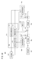
さらに、第1ガスセンサ10Aは、図2に模式的に示すように、酸素濃度調整室18内の酸素濃度を制御する酸素濃度制御手段100と、第1センサ素子12Aの温度を制御する温度制御手段102と、測定室20内の特定成分(NO)の濃度を測定する特定成分測定手段104と、予備酸素濃度制御手段106と、駆動制御手段108と、目的成分取得手段110とを有する。
Further, as shown schematically in FIG. 2, the
なお、酸素濃度制御手段100、温度制御手段102、特定成分測定手段104、予備酸素濃度制御手段106、駆動制御手段108及び目的成分取得手段110は、例えば1つ又は複数のCPU(中央処理ユニット)と記憶装置等を有する1以上の電子回路にて構成される。電子回路は、例えば記憶装置に記憶されているプログラムをCPUが実行することにより、所定の機能が実現されるソフトウェア機能部でもある。もちろん、複数の電子回路を機能に合わせて接続したFPGA(Field-Programmable Gate Array)等の集積回路で構成してもよい。 The oxygen concentration control means 100, the temperature control means 102, the specific component measuring means 104, the preliminary oxygen concentration control means 106, the drive control means 108, and the target component acquisition means 110 are, for example, one or a plurality of CPUs (central processing units). It is composed of one or more electronic circuits having a storage device and the like. The electronic circuit is also a software function unit in which a predetermined function is realized by, for example, the CPU executing a program stored in a storage device. Of course, it may be composed of an integrated circuit such as an FPGA (Field-Programmable Gate Array) in which a plurality of electronic circuits are connected according to their functions.
従来は、NO、NH3の目的成分に対して、酸素濃度調整室18内で全てをNOに変換した後、測定室20に導入し、これら2成分の総量を測定していた。つまり、2つの目的成分毎の濃度、すなわち、NO及びNH3の各濃度を測定することができなかった。Conventionally, all of the target components of NO and NH 3 have been converted to NO in the oxygen
これに対して、第1ガスセンサ10Aは、上述した酸素濃度調整室18、酸素濃度制御手段100及び温度制御手段102及び特定成分測定手段104に加えて、予備調整室21、予備酸素濃度制御手段106、駆動制御手段108及び目的成分取得手段110を具備することで、NO及びNH3の各濃度を取得することができるようにしたものである。On the other hand, in the
酸素濃度制御手段100は、予め設定された酸素濃度の条件と、第1酸素分圧検出センサセル50(図1参照)において生じる第1起電力V1とに基づいて、第1可変電源46をフィードバック制御することにより、酸素濃度調整室18内の酸素濃度を、上記条件に従った濃度に調整する。
The oxygen concentration control means 100 feedback-controls the first
温度制御手段102は、予め設定されたセンサ温度の条件と、第1センサ素子12Aの温度を計測する温度センサ(図示せず)からの計測値とに基づいて、ヒータ72をフィードバック制御することにより、第1センサ素子12Aの温度を、上記条件に従った温度に調整する。
Temperature control means 102, a condition of the sensor temperature which is set in advance, based on the measured value from the temperature sensor for measuring the temperature of the
第1ガスセンサ10Aは、これら酸素濃度制御手段100又は温度制御手段102、あるいは酸素濃度制御手段100及び温度制御手段102によって、酸素濃度調整室18内のNOを分解させることなく、NH3を全てNOに変換するように制御する。The
予備酸素濃度制御手段106は、予め設定された酸素濃度の条件と、予備酸素分圧検出センサセル84(図1参照)において生じる予備起電力V0とに基づいて、予備可変電源86をフィードバック制御することにより、予備調整室21内の酸素濃度を、条件に従った濃度に調整する。
The preliminary oxygen concentration control means 106 feedback-controls the preliminary
この予備酸素濃度制御手段106によって、予備調整室21内のNOを分解させることなく、NH3が全てNOに変換される。By this preliminary oxygen concentration control means 106, all NH 3 is converted into NO without decomposing NO in the
駆動制御手段108は、予備酸素濃度制御手段106の駆動及び停止を制御する。これによって、予備ポンプセル80がON/OFF制御される。予備酸素濃度制御手段106の駆動中は、予備ポンプセル80がONとなることから、上述したように、予備調整室21内のNH3は全てNOに変換され、第2拡散律速部32を介して酸素濃度調整室18に流入する。予備酸素濃度制御手段106の停止中は、予備ポンプセル80がOFFになることから、予備調整室21内のNH3はNOに変換されることなく、第2拡散律速部32を介して酸素濃度調整室18に流入する。The drive control means 108 controls the drive and stop of the reserve oxygen concentration control means 106. As a result, the
目的成分取得手段110は、予備酸素濃度制御手段106の駆動時における特定成分測定手段104からのセンサ出力と、予備酸素濃度制御手段106の停止時における特定成分測定手段104からのセンサ出力との差に基づいて、NO及びNH3の各濃度を取得する。The target component acquisition means 110 is the difference between the sensor output from the specific component measuring means 104 when the preliminary oxygen concentration controlling means 106 is driven and the sensor output from the specific component measuring means 104 when the preliminary oxygen concentration controlling means 106 is stopped. Based on, each concentration of NO and NH 3 is obtained.
ここで、第1ガスセンサ10Aの処理動作について、図3及び図4も参照しながら説明する。
Here, the processing operation of the
先ず、駆動制御手段108によって予備酸素濃度制御手段106が停止している期間では、図3に示すように、ガス導入口16を通じて導入したNH3は、酸素濃度調整室18まで到達する。酸素濃度調整室18では、酸素濃度制御手段100によって、NH3を全てNOに変換するように制御されていることから、予備調整室21から酸素濃度調整室18に流入したNH3は酸素濃度調整室18内でNH3→NOの酸化反応が起こり、酸素濃度調整室18内の全てのNH3がNOに変換される。従って、ガス導入口16を通じて導入されたNH3は、第1拡散律速部30及び第2拡散律速部32をNH3の拡散係数2.2cm2/secの速度で通過し、酸素濃度調整室18内でNOに変換された後は、第3拡散律速部34をNOの拡散係数1.8cm2/secの速度で通過して、隣接する測定室20内に移動する。First, during the period in which the reserve oxygen concentration control means 106 is stopped by the drive control means 108, the NH 3 introduced through the
一方、駆動制御手段108によって予備酸素濃度制御手段106が駆動している期間では、図4に示すように、予備調整室21内でNH3→NOの酸化反応が起こり、ガス導入口16を通じて導入された全てのNH3がNOに変換される。従って、NH3は第1拡散律速部30をNH3の拡散係数2.2cm2/secで通過するが、予備調整室21より奥にある第2拡散律速部32以降はNOの拡散係数1.8cm2/secの速度で測定室20に移動する。On the other hand, during the period in which the preliminary oxygen concentration control means 106 is being driven by the drive control means 108, an oxidation reaction of NH 3 → NO occurs in the
すなわち、予備酸素濃度制御手段106が停止状態から駆動状態に切り替わることで、NH3の酸化反応が起こる場所が酸素濃度調整室18から予備調整室21に移動する。That is, when the preliminary oxygen concentration control means 106 is switched from the stopped state to the driven state, the place where the oxidation reaction of NH 3 occurs moves from the oxygen
NH3の酸化反応が起こる場所が酸素濃度調整室18から予備調整室21に移動することは、被測定ガス中のNH3が第2拡散律速部32を通過する際の状態がNH3からNOに変わることに等しい。そして、NO、NH3は各々異なる拡散係数を持つため、第2拡散律速部32をNOで通過するか、NH3で通過するかの違いは、測定室20に流れ込むNO量の違いに相当するため、測定用ポンプセル61に流れる測定ポンプ電流Ip3を変化させる。The fact that the place where the oxidation reaction of NH 3 occurs moves from the oxygen
この場合、予備ポンプセル80のON時の測定ポンプ電流Ip3onと、予備ポンプセル80のOFF時の測定ポンプ電流Ip3offの変化量ΔIp3は、被測定ガス中のNH3の濃度によって一義的に決まる。そのため、予備ポンプセル80のON時又はOFF時の測定ポンプ電流Ip3on又はIp3offと、上述した測定ポンプ電流Ip3の変化量ΔIp3とからNOとNH3の各濃度を算出することができる。In this case, the change amount ΔIp3 of the measurement pump current Ip3on when the
従って、目的成分取得手段110では、予備ポンプセル80のON時の測定ポンプ電流Ip3onと、該測定ポンプ電流Ip3onと予備ポンプセル80のOFF時の測定ポンプ電流Ip3offとの変化量ΔIp3と、第1マップ112A(図2参照)とに基づいてNO及びNH3の各濃度を取得する。Therefore, in the target component acquisition means 110, the measurement pump current Ip3on when the
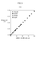
第1マップ112Aは、グラフ化して示すと、図5に示すように、横軸に、被測定ガス中のNH3濃度(ppm)が設定され、縦軸に、予備ポンプセル80のON時の測定ポンプ電流Ip3onと予備ポンプセル80のOFF時の測定ポンプ電流Ip3offとの差、すなわち、変化量ΔIp3が設定されたグラフとなる。図5では、代表的に、予備ポンプセル80のOFF時における測定ポンプ電流値のNO濃度換算値が例えば100ppm系、50ppm系、25ppm系、0ppm系であるポイントをプロットしたグラフを示す。分かり易くテーブルの形式で示すと、図6に示すような内容となる。これらの濃度は、実験あるいはシミュレーションにて求めている。
図6からわかるように、第1マップ112Aを使用することで、予備ポンプセル80のOFF時の測定ポンプ電流Ip3off(すなわち、従来の直列2室型NOxセンサと同様の測定ポンプ電流値)に基づいて、100ppm系、50ppm系、25ppm系、0ppm系のいずれかを割り出し、変化量ΔIp3に基づいてNOとNH3の各濃度を同定する。As can be seen from FIG. 6, by using the
すなわち、予備ポンプセル80のOFF時の測定ポンプ電流Ip3offと、変化量ΔIp3とから第1マップ112A上のポイントを特定することで、NO濃度とNH3濃度を同定することができる。例えば従来の直列2室型NOxセンサと同様の測定ポンプ電流Ip3offが2.137μAであった場合、上記直列2室型NOxセンサでは、NOとNH3の合計濃度が概ね100ppmであることしかわからなかった。しかし、第1ガスセンサ10Aにおいては、変化量ΔIp3を組み合わせることで、ポイントp1では、NO濃度が100ppm、NH3濃度が0ppm、ポイントp2では、NO濃度が80ppm、NH3濃度が17.6ppm、ポイントp3では、NO濃度が60ppm、NH3濃度が35.2ppmのようにNO濃度とNH3濃度を個別に特定することができる。第1マップ112A上に該当するポイントが存在しない場合は、最も近いポイントを特定し、例えば既知の近似計算にてNO濃度とNH3濃度を求めればよい。That is, the measured pump current Ip3off during OFF of the
また、以下の手法にてNO濃度とNH3濃度を求めてもよい。すなわち、上述した図5に示すように、予め実験あるいはシミュレーションにて、変化量ΔIp3とNH3濃度との関係を求めておき、予備ポンプセル80のON時とOFF時の変化量ΔIp3からNH3濃度を求める。そして、予備ポンプセル80のOFF時におけるセンサ出力から得られるNO濃度、すなわち、NOとNH3の濃度の全てをNOに換算した総NO濃度から、上述して求めたNH3濃度を差し引いてNO濃度を求めてもよい。Also, it may be obtained NO concentrations and NH 3 concentrations in the following manner. That is, as shown in FIG. 5 described above, in advance experiment or simulation, to previously obtain a relation between the variation ΔIp3 and NH 3 concentration, NH 3 concentration from the change amount ΔIp3 during ON
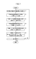
ここで、第1ガスセンサ10AによるNO及びNH3の測定処理について図7のフローチャートを参照しながら説明する。Here, the measurement processing of NO and NH 3 by the
先ず、図7のステップS1において、第1ガスセンサ10Aは、ガス導入口16を通じて予備調整室21内にNO及びNH3が混在する被測定ガスを導入する。First, in step S1 of FIG. 7, the
ステップS2において、駆動制御手段108は、予備酸素濃度制御手段106を駆動する。これにより、予備ポンプセル80がONとなる。
In step S2, the drive control means 108 drives the reserve oxygen concentration control means 106. As a result, the
ステップS3において、特定成分測定手段104は、予備ポンプセル80のON時におけるNO濃度を測定する。すなわち、測定ポンプ電流Ip3onを得る。この測定ポンプ電流Ip3onは目的成分取得手段110に入力される。
In step S3, the specific component measuring means 104 measures the NO concentration when the
ステップS4において、駆動制御手段108は、予備酸素濃度制御手段106の駆動を停止する。これにより、予備ポンプセル80がOFFとなる。
In step S4, the drive control means 108 stops driving the reserve oxygen concentration control means 106. As a result, the
ステップS5において、特定成分測定手段104は、予備ポンプセル80のOFF時におけるNO濃度を測定する。すなわち、測定ポンプ電流Ip3offを得る。この測定ポンプ電流Ip3offは目的成分取得手段110に入力される。
In step S5, the specific component measuring means 104 measures the NO concentration when the
ステップS6において、目的成分取得手段110は、予備ポンプセル80のOFF時の測定ポンプ電流Ip3offと、該測定ポンプ電流Ip3offと予備ポンプセル80のON時の測定ポンプ電流Ip3onとの変化量ΔIp3と、第1マップ112Aとに基づいてNO濃度及びNH3濃度を取得する。In step S6, the target component acquisition means 110 includes the measurement pump current Ip3off when the
すなわち、目的成分取得手段110は、測定ポンプ電流Ip3offと、変化量ΔIp3とから第1マップ112A上のポイントを特定する。そして、第1マップ112Aから、特定したポイントに対応するNO濃度及びNH3濃度を読み出して、今回、測定したNO濃度及びNH3濃度とする。第1マップ112A上に該当するポイントが存在しない場合は、上述したように、最も近いポイントを特定し、例えば既知の近似計算にてNO濃度とNH3濃度を求める。That is, the target component acquisition means 110 identifies a point on the
あるいは、図5に示す変化量ΔIp3とNH3濃度との関係に基づいて、予備ポンプセル80のON時とOFF時の変化量ΔIp3からNH3濃度を求める。そして、予備ポンプセル80のOFF時におけるセンサ出力から得られるNO濃度、すなわち、NOとNH3の濃度の全てをNOに換算した総NO濃度から、上述して求めたNH3濃度を差し引いてNO濃度を求めてもよい。Alternatively, based on the relationship between the change amount ΔIp3 and NH 3 concentrations shown in Figure 5, determine the NH 3 concentration from the change amount ΔIp3 during ON
ステップS7において、第1ガスセンサ10Aは、NO及びNH3の測定処理の終了要求(電源断、メンテナンス等)があるか否かを判別する。終了要求がなければ、ステップS1以降の処理を繰り返す。そして、ステップS7において、終了要求があった段階で、第1ガスセンサ10AでのNO及びNH3の測定処理を終了する。In step S7, the
このように、第1ガスセンサ10Aは、予め実験的に測定した、予備酸素濃度制御手段106の停止時における特定成分測定手段104からのセンサ出力(Ip3off)と、予備酸素濃度制御手段106の駆動時と停止時における特定成分測定手段104からのセンサ出力の差(ΔIp3)とで特定されるポイント毎にそれぞれNO濃度及びNH3濃度の関係が登録された第1マップ112Aを使用するようにしている。あるいは、図5に示すように、予め実験的に求めた変化量ΔIp3とNH3濃度との関係を使用するようにしている。もちろん、第1マップ112Aで兼用してもよい。As described above, the
そして、実使用中の予備酸素濃度制御手段106の停止時における特定成分測定手段104からのセンサ出力(Ip3off)と、予備酸素濃度制御手段106の駆動時と停止時における特定成分測定手段104からのセンサ出力の差(ΔIp3)を、第1マップ112Aと比較して、NO及びNH3の各濃度を求めるようにしている。Then, the sensor output (Ip3off) from the specific component measuring means 104 when the preliminary oxygen concentration controlling means 106 is actually used and the specific component measuring means 104 when the preliminary oxygen concentration controlling means 106 is driven and stopped the difference of the sensor output (ΔIp3), as compared with the
これにより、排気ガスのような未燃成分、酸素の存在下に共存する複数目的成分(例えばNO、NH3)の雰囲気下においても、複数目的成分の各濃度を長期間にわたり精度よく測定することができる。As a result, each concentration of the multipurpose component can be accurately measured over a long period of time even in an atmosphere of an unburned component such as exhaust gas and a multipurpose component (for example, NO, NH 3 ) coexisting in the presence of oxygen. Can be done.
しかも、第1ガスセンサ10Aは、従来では実現できなかったNOとNH3の各濃度を測定する処理を、ハードウェアとしての各種測定装置等を別途付加することなく、第1ガスセンサ10Aの制御系のソフトウェアを変更するだけで、容易に実現することができる。その結果、NOx浄化システムの制御並びに故障検知に対する精度を高めることができる。特に、SCRシステム下流の排気ガス中のNO及びNH3とを区別することが可能となり、SCRシステムの尿素注入量の精密制御、及び劣化検知に寄与する。Moreover, the
次に、第2の実施の形態に係るガスセンサ(以下、第2ガスセンサ10Bと記す)について図8〜図13を参照しながら説明する。
Next, the gas sensor according to the second embodiment (hereinafter, referred to as the
この第2ガスセンサ10Bは、図8に示すように、上述した第1ガスセンサ10Aの第1センサ素子12Aと同様の構成を有する第2センサ素子12Bを具備するが、第2目的成分がNO2である点で異なる。As shown in FIG. 8, the
従って、第2ガスセンサ10Bは、これら酸素濃度制御手段100又は温度制御手段102、あるいは酸素濃度制御手段100及び温度制御手段102によって、酸素濃度調整室18内のNOを分解させることなく、NO2を全てNOに変換するように制御する。Therefore, the
予備酸素濃度制御手段106は、予め設定された酸素濃度の条件と、予備酸素分圧検出センサセル84(図1参照)において生じる予備起電力V0とに基づいて、予備可変電源86をフィードバック制御することにより、予備調整室21内の酸素濃度を、条件に従った濃度に調整する。
The preliminary oxygen concentration control means 106 feedback-controls the preliminary
この予備酸素濃度制御手段106によって、予備調整室21内のNOを分解させることなく、NO2が全てNOに変換される。By this preliminary oxygen concentration control means 106, all NO 2 is converted into NO without decomposing NO in the
駆動制御手段108は、予備酸素濃度制御手段106の駆動及び停止を制御する。これによって、予備ポンプセル80がON/OFF制御される。予備酸素濃度制御手段106の駆動中は、予備ポンプセル80がONとなることから、上述したように、予備調整室21内のNO2は全てNOに変換され、第2拡散律速部32を介して酸素濃度調整室18に流入する。予備酸素濃度制御手段106の停止中は、予備ポンプセル80がOFFになることから、予備調整室21内のNO2はNOに変換されることなく、第2拡散律速部32を介して酸素濃度調整室18に流入する。The drive control means 108 controls the drive and stop of the reserve oxygen concentration control means 106. As a result, the
目的成分取得手段110は、予備酸素濃度制御手段106の駆動時における特定成分測定手段104からのセンサ出力と、予備酸素濃度制御手段106の停止時における特定成分測定手段104からのセンサ出力との差に基づいて、NO及びNO2の各濃度を取得する。The target component acquisition means 110 is the difference between the sensor output from the specific component measuring means 104 when the preliminary oxygen concentration controlling means 106 is driven and the sensor output from the specific component measuring means 104 when the preliminary oxygen concentration controlling means 106 is stopped. Based on, each concentration of NO and NO 2 is acquired.
ここで、第2ガスセンサ10Bの処理動作について、図9及び図10も参照しながら説明する。
Here, the processing operation of the
先ず、駆動制御手段108によって予備酸素濃度制御手段106が停止している期間では、図9に示すように、ガス導入口16を通じて導入したNO2は、酸素濃度調整室18まで到達する。酸素濃度調整室18では、酸素濃度制御手段100によって、NO2を全てNOに変換するように制御されていることから、予備調整室21から酸素濃度調整室18に流入したNO2は酸素濃度調整室18内でNO2→NOの分解反応が起こり、酸素濃度調整室18内の全てのNO2がNOに変換される。First, during the period in which the reserve oxygen concentration control means 106 is stopped by the drive control means 108, NO 2 introduced through the
一方、駆動制御手段108によって予備酸素濃度制御手段106が駆動している期間では、図10に示すように、予備調整室21内でNO2→NOの分解反応が起こり、ガス導入口16を通じて導入された全てのNO2がNOに変換される。On the other hand, during the period in which the reserve oxygen concentration control means 106 is driven by the drive control means 108, as shown in FIG. 10, a decomposition reaction of NO 2 → NO occurs in the
すなわち、予備酸素濃度制御手段106が停止状態から駆動状態に切り替わることで、NO2の分解反応が起こる場所が酸素濃度調整室18から予備調整室21に移動することとなる。That is, when the preliminary oxygen concentration control means 106 is switched from the stopped state to the driven state, the place where the decomposition reaction of NO 2 occurs moves from the oxygen
NO2の分解反応が起こる場所が酸素濃度調整室18から予備調整室21に移動することは、被測定ガス中のNO2が第2拡散律速部32を通過する際の状態がNO2からNOに変わることに等しい。そして、NO、NO2は各々異なる拡散係数を持つため、第2拡散律速部32をNOで通過するか、NO2で通過するかの違いは、測定室20に流れ込むNO量の違いに相当するため、測定用ポンプセル61に流れる測定ポンプ電流Ip3を変化させる。The fact that the place where the decomposition reaction of NO 2 occurs moves from the oxygen
この場合、予備ポンプセル80のON時の測定ポンプ電流Ip3onと、予備ポンプセル80のOFF時の測定ポンプ電流Ip3offの変化量ΔIp3は、被測定ガス中のNO2の濃度によって一義的に決まる。そのため、予備ポンプセル80のON時又はOFF時の測定ポンプ電流Ip3on又はIp3offと、上述した測定ポンプ電流Ip3の変化量ΔIp3とからNOとNO2の各濃度を算出することができる。In this case, the change amount ΔIp3 of the measurement pump current Ip3on when the
従って、目的成分取得手段110では、予備ポンプセル80のOFF時の測定ポンプ電流Ip3offと、該測定ポンプ電流Ip3offと予備ポンプセル80のON時の測定ポンプ電流Ip3onとの変化量ΔIp3と、第2マップ112B(図8参照)とに基づいてNO及びNO2の各濃度を取得する。Therefore, in the target component acquisition means 110, the measurement pump current Ip3off when the
第2マップ112Bは、グラフ化して示すと、図11に示すように、横軸に、被測定ガス中のNO2濃度(ppm)が設定され、縦軸に、予備ポンプセル80のON時の測定ポンプ電流Ip3onと予備ポンプセル80のOFF時の測定ポンプ電流Ip3offとの差、すなわち、変化量ΔIp3が設定されたグラフとなる。図11では、代表的に、予備ポンプセル80のOFF時における測定ポンプ電流値のNO濃度換算値が例えば500ppm系、250ppm系、100ppm系であるポイントをプロットしたグラフを示す。分かり易くテーブルの形式で示すと、図12に示すような内容となる。これらの濃度は、実験あるいはシミュレーションにて求めている。When the
図12からわかるように、第2マップ112Bを使用することで、予備ポンプセル80のOFF時の測定ポンプ電流Ip3off(すなわち、従来の直列2室型NOxセンサと同様の測定ポンプ電流値)に基づいて、500ppm系、250ppm系、100ppm系のいずれかを割り出し、変化量ΔIp3に基づいてNOとNO2の各濃度を同定する。As can be seen from FIG. 12, by using the
すなわち、予備ポンプセル80のOFF時の測定ポンプ電流Ip3offと、変化量ΔIp3とから第2マップ112B上のポイントを特定することで、NO濃度とNO2濃度を同定することができる。例えば従来の直列2室型NOxセンサと同様の測定ポンプ電流Ip3offが10.67μAであった場合、上記直列2室型NOxセンサでは、NOとNO2の合計濃度が概ね500ppmであることしかわからなかったが、第2ガスセンサ10Bにおいては、変化量ΔIp3を組み合わせることでポイントp101では、NO濃度が500ppm、NO2濃度が0ppm、ポイントp102では、NO濃度が400ppm、NO2濃度が116ppm、ポイントp103では、NO濃度が300ppm、NO2濃度が233ppmのようにNOとNO2濃度を個別に特定することができる。第2マップ112B上に該当するポイントが存在しない場合は、最も近いポイントを特定し、例えば既知の近似計算にてNO濃度とNO2濃度を求めればよい。That is, the NO concentration and the NO 2 concentration can be identified by specifying the points on the
また、以下の手法にてNO濃度とNO2濃度を求めてもよい。すなわち、上述した図11に示すように、予め実験あるいはシミュレーションにて、変化量ΔIp3とNO2濃度との関係を求めておき、予備ポンプセル80のON時とOFF時の変化量ΔIp3からNO2濃度を求める。そして、予備ポンプセル80のOFF時におけるセンサ出力から得られるNO濃度、すなわち、NOとNO2の濃度の全てをNOに換算した総NO濃度から、上述して求めたNO2濃度を差し引いてNO濃度を求めてもよい。Further, the NO concentration and the NO 2 concentration may be obtained by the following method. That is, as shown in FIG. 11 described above, in advance experiment or simulation, to previously obtain a relation between the variation ΔIp3 and NO 2 concentrations, NO 2 concentration from the change amount ΔIp3 during ON
ここで、第2ガスセンサ10BによるNO及びNO2の測定処理について図13のフローチャートを参照しながら説明する。Here, the measurement process of NO and NO 2 by the
先ず、図13のステップS101において、第2ガスセンサ10Bは、ガス導入口16を通じて予備調整室21内にNO及びNO2が混在する被測定ガスを導入する。First, in step S101 of FIG. 13, the
ステップS102において、駆動制御手段108は、予備酸素濃度制御手段106を駆動する。これにより、予備ポンプセル80がONとなる。
In step S102, the drive control means 108 drives the reserve oxygen concentration control means 106. As a result, the
ステップS103において、特定成分測定手段104は、予備ポンプセル80のON時におけるNO濃度を測定する。すなわち、測定ポンプ電流Ip3onを得る。この測定ポンプ電流Ip3onは目的成分取得手段110に入力される。
In step S103, the specific component measuring means 104 measures the NO concentration when the
ステップS104において、駆動制御手段108は、予備酸素濃度制御手段106の駆動を停止する。これにより、予備ポンプセル80がOFFとなる。
In step S104, the drive control means 108 stops driving the reserve oxygen concentration control means 106. As a result, the
ステップS105において、特定成分測定手段104は、予備ポンプセル80のOFF時におけるNO濃度を測定する。すなわち、測定ポンプ電流Ip3offを得る。この測定ポンプ電流Ip3offは目的成分取得手段110に入力される。
In step S105, the specific component measuring means 104 measures the NO concentration when the
ステップS106において、目的成分取得手段110は、予備ポンプセル80のOFF時の測定ポンプ電流Ip3offと、該測定ポンプ電流Ip3offと予備ポンプセル80のON時の測定ポンプ電流Ip3onとの変化量ΔIp3と、第2マップ112Bとに基づいてNO濃度及びNO2濃度を取得する。In step S106, the target component acquisition means 110 has a measurement pump current Ip3off when the
すなわち、目的成分取得手段110は、測定ポンプ電流Ip3offと、変化量ΔIp3とから第2マップ112B上のポイントを特定する。そして、第2マップ112Bから、特定したポイントに対応するNO濃度及びNO2濃度を読み出して、今回、測定したNO濃度及びNO2濃度とする。第2マップ112B上に該当するポイントが存在しない場合は、上述したように、最も近いポイントを特定し、例えば既知の近似計算にてNO濃度とNO2濃度を求める。That is, the target component acquisition means 110 identifies a point on the
あるいは、図11に示す変化量ΔIp3とNO2濃度との関係に基づいて、予備ポンプセル80のON時とOFF時の変化量ΔIp3からNO2濃度を求める。そして、予備ポンプセル80のOFF時におけるセンサ出力から得られるNO濃度、すなわち、NOとNO2の濃度の全てをNOに換算した総NO濃度から、上述して求めたNO2濃度を差し引いてNO濃度を求めてもよい。Alternatively, based on the relationship between the change amount ΔIp3 and NO 2 concentrations shown in Figure 11, obtaining the NO 2 concentration from the change amount ΔIp3 during ON
ステップS107において、第2ガスセンサ10Bは、NO及びNO2の測定処理の終了要求(電源断、メンテナンス等)があるか否かを判別する。終了要求がなければ、ステップS101以降の処理を繰り返す。そして、ステップS107において、終了要求があった段階で、第2ガスセンサ10BでのNO及びNO2の測定処理を終了する。In step S107, the
このように、第2ガスセンサ10Bは、予め実験的に測定した、予備酸素濃度制御手段106の停止時における特定成分測定手段104からのセンサ出力(Ip3off)と、予備酸素濃度制御手段106の駆動時と停止時における特定成分測定手段104からのセンサ出力の差(ΔIp3)とで特定されるポイント毎にそれぞれNO濃度及びNO2濃度の関係が登録された第2マップ112Bを使用するようにしている。あるいは、図11に示すように、予め実験的に求めた変化量ΔIp3とNO2濃度との関係を使用するようにしている。もちろん、第2マップ112Bで兼用してもよい。As described above, the
そして、実使用中の予備酸素濃度制御手段106の停止時における特定成分測定手段104からのセンサ出力(Ip3off)と、予備酸素濃度制御手段106の駆動時と停止時における特定成分測定手段104からのセンサ出力の差(ΔIp3)を、第2マップ112Bと比較して、NO及びNO2の各濃度を求めるようにしている。Then, the sensor output (Ip3off) from the specific component measuring means 104 when the preliminary oxygen concentration controlling means 106 is actually used and the specific component measuring means 104 when the preliminary oxygen concentration controlling means 106 is driven and stopped The difference in sensor output (ΔIp3) is compared with the
これにより、排気ガスのような未燃成分、酸素の存在下に共存する複数目的成分(例えばNO、NO2)の雰囲気下においても、複数目的成分の各濃度を長期間にわたり精度よく測定することができる。As a result, each concentration of the multipurpose component can be accurately measured over a long period of time even in an atmosphere of an unburned component such as exhaust gas and a multipurpose component (for example, NO, NO 2 ) coexisting in the presence of oxygen. Can be done.
しかも、第2ガスセンサ10Bは、従来では実現できなかったNOとNO2の各濃度を測定する処理を、ハードウェアとしての各種測定装置等を別途付加することなく、第2ガスセンサ10Bの制御系のソフトウェアを変更するだけで、容易に実現することができる。その結果、NOx浄化システムの制御並びに故障検知に対する精度を高めることができる。特に、DOC(Diesel Oxdation Catalyst)触媒下流の排気ガス中のNOとNO2とを区別することが可能となり、DOC触媒の劣化検知に寄与する。Moreover, the
本発明の要旨は、下記(a)〜(c)であり、NH3やNO2がNOに変化する反応はセンサ出力の変動が得られる範囲から任意に選ぶことができる。
(a) NH3やNO2がNOに変化する反応を、所定の拡散抵抗を持った拡散律速部の前後で意図的に発生させる。
(b) (a)によって、NOとNH3又はNOとNO2の拡散係数の違いによって生ずるセンサ出力の変動からNH3もしくはNO2の濃度を求める。
(c) さらに、センサ出力自身によって得られるNOとNH3の合計濃度、もしくはNOとNO2の合計濃度と前記変動によって得られるNH3もしくはNO2の濃度を比較してNO濃度を得る。The gist of the present invention is the following (a) to (c), and the reaction in which NH 3 or NO 2 changes to NO can be arbitrarily selected from the range in which the fluctuation of the sensor output can be obtained.
(A) A reaction in which NH 3 or NO 2 changes to NO is intentionally generated before and after the diffusion rate-determining portion having a predetermined diffusion resistance.
(B) According to (a), the concentration of NH 3 or NO 2 is obtained from the fluctuation of the sensor output caused by the difference in the diffusion coefficient of NO and NH 3 or NO and NO 2 .
(C) Further, the total concentration of NO and NH 3 obtained by the sensor output itself, or the total concentration of NO and NO 2 is compared with the concentration of NH 3 or NO 2 obtained by the fluctuation to obtain the NO concentration.
次に、第1ガスセンサ10A及び第2ガスセンサ10Bを有する排ガス浄化システム200について図14〜図19を参照しながら説明する。
Next, the exhaust
この排ガス浄化システム200は、図14に示すように、ディーゼルエンジン等の燃焼装置202の排ガスを浄化するシステムである。排ガス浄化システム200は、燃焼装置202からのハイドロカーボンや酸化炭素を還元するDOC触媒204と、DOC触媒204の下流側に設置されたSCR触媒206と、尿素タンク208に貯留された尿素水を、SCR触媒206にその上流側から注入する尿素水注入インジェクタ210とを有する。注入は噴霧による注入も含む。燃焼装置202は、例えばECU212(電子制御装置)による所定の燃焼制御に基づいて負荷(クランク軸等)にエネルギーを付与する。
As shown in FIG. 14, this exhaust
そして、第1ガスセンサ10Aの第1センサ素子12AはSCR触媒206の下流側に設置され、第2ガスセンサ10Bの第2センサ素子12BはDOC触媒204とSCR触媒206との間、より詳細には、DOC触媒204と尿素水注入インジェクタ210との間に設置される。
Then, the
第1ガスセンサ10Aを駆動制御する第1制御回路214Aは、第1センサ素子12AとECU212との間に接続され、第2ガスセンサ10Bを駆動制御する第2制御回路214Bは、第2センサ素子12BとECU212との間に接続されている。
The
第1制御回路214Aは、第1ガスセンサ10Aに特化した上述した酸素濃度制御手段100、温度制御手段102、特定成分測定手段104、予備酸素濃度制御手段106、駆動制御手段108、目的成分取得手段110等を有する。
The
同様に、第2制御回路214Bも、第2ガスセンサ10Bに特化した上述した酸素濃度制御手段100、温度制御手段102、特定成分測定手段104、予備酸素濃度制御手段106、駆動制御手段108、目的成分取得手段110等を有する。
Similarly, the
また、ECU212内には、第1制御回路214AからのNO濃度及びNH3濃度に基づいて尿素水注入インジェクタ210の開度を制御する開度制御手段216と、NO濃度及びNH3濃度に基づいてSCR触媒206の劣化状態を検知するSCR劣化検知手段218と、第2制御回路214BからのNO濃度及びNO2濃度に基づいてDOC触媒204の劣化状態を検知するDOC劣化検知手段220とを有する。Further, in the
なお、ECU212についても、例えば1つ又は複数のCPU(中央処理ユニット)と記憶装置等を有する1以上の電子回路にて構成される。上記開度制御手段216、SCR劣化検知手段218、DOC劣化検知手段220は、例えば記憶装置に記憶されているプログラムをCPUが実行することにより、所定の機能が実現されるソフトウェア機能部でもある。もちろん、複数の電子回路を機能に合わせて接続したFPGA等の集積回路で構成してもよい。
The
先ず、比較のために、尿素水の注入量を増加させた場合における従来のガスセンサにて測定されたNO濃度の変化、NH3の排出量の変化、SCR効率の変化を図15を参照しながら説明する。First, for comparison, the change in NO concentration, the change in NH 3 emission, and the change in SCR efficiency measured by a conventional gas sensor when the amount of urea water injected is increased are shown with reference to FIG. explain.
図15は左側の縦軸にSCR効率(SCR触媒206のNOx浄化効率(%))、右側の縦軸にNH3の排出量(ppm)及び従来のガスセンサにて測定されたNO濃度(ppm)を示し、横軸に尿素水注入量を示す。図15において、特性曲線LaがNO濃度を示し、特性曲線LbがSCR効率を示し、特性曲線LcがNH3排出量を示す。In FIG. 15, the vertical axis on the left side is the SCR efficiency (NOx purification efficiency (%) of the SCR catalyst 206), the vertical axis on the right side is the emission amount of NH 3 (ppm), and the NO concentration (ppm) measured by a conventional gas sensor. Is shown, and the amount of urea water injected is shown on the horizontal axis. 15, characteristic curve La represents the NO concentration, the characteristic curve Lb represents SCR efficiency characteristic curve Lc shows a NH 3 emissions.
図15からわかるように、尿素水注入量を増加させると、SCR効率は高くなるが、排出されるNH3の量が増加する。そのため、ガスセンサによる目標検知範囲Zaとして、SCR効率の下限が90%で、且つ、NH3排出量の上限が10ppmの範囲に設定することが好ましい。As can be seen from FIG. 15, when the urea water injection amount is increased, the SCR efficiency is increased, but the amount of NH 3 discharged is increased. Therefore, it is preferable to set the lower limit of the SCR efficiency to 90% and the upper limit of the NH 3 emission amount to the range of 10 ppm as the target detection range Za by the gas sensor.
しかし、NH3排出量の増加による干渉の影響によって、SCR効率が90%以上の領域では、ガスセンサの感度(尿素水注入量の増加幅に対するガスセンサの測定値の変化幅ΔNO)が小さくなり、しかも、エラー成分Erも含まれるため、尿素水注入量の精密な制御ができないという問題があった。However, due to the influence of interference due to the increase in NH 3 emission, the sensitivity of the gas sensor (change width ΔNO of the measured value of the gas sensor with respect to the increase width of the urea water injection amount) becomes small in the region where the SCR efficiency is 90% or more. Since the error component Er is also included, there is a problem that the urea water injection amount cannot be precisely controlled.
一方、尿素水の注入量を増加させた場合における第1ガスセンサ10Aのセンサ出力の変化、NH3排出量の変化、SCR効率の変化を図16に示す。図16において、左側の縦軸にSCR効率(%)、右側の縦軸にNH3排出量(ppm)及び第1ガスセンサ10Aのセンサ出力Ip3(μA)を示し、横軸に尿素水注入量を示す。図16において、特性曲線Ldがセンサ出力を示し、特性曲線LbがSCR効率を示し、特性曲線LcがNH3排出量を示す。On the other hand, FIG. 16 shows a change in the sensor output of the
第1ガスセンサ10Aでは、予備酸素濃度制御手段106の駆動及び停止、すなわち、予備ポンプセル80のON及びOFFに応じて特定成分測定手段104からのセンサ出力Ip3が変動する。このセンサ出力Ip3の変動(ΔIp3)は、NH3の濃度が高くなるにつれて大きくなっている。従って、上述したように、予備ポンプセル80のON時の測定ポンプ電流Ip3onと、該測定ポンプ電流Ip3onと予備ポンプセル80のOFF時の測定ポンプ電流Ip3offとの変化量ΔIp3と、第1マップ112Aとに基づいてNO及びNH3の各濃度を取得することができる。In the
従来では、酸素濃度調整室18で、NOを分解させることなく、NH3を酸化反応させてNOに変換した際のセンサ出力のみでNOとNH3の濃度を測定していた。これに対し、第1ガスセンサ10Aでは、予備調整室21で、NOを分解させることなく、NH3を酸化反応させずにそのまま酸素濃度調整室18に導入させた際のセンサ出力Ip3offに加えて、変化量ΔIp3に基づいて、第1マップ112AからNO濃度とNH3濃度を取得している。変化量ΔIp3は、上記センサ出力Ip3offと、予備調整室21で、NOを分解させることなく、NH3を酸化反応させた際のセンサ出力Ip3onとの変化量を示す。Conventionally, in the oxygen
そのため、第1ガスセンサ10Aのセンサ出力に対応する濃度は、NH3濃度(変化量ΔIp3に対応する濃度)と、NO濃度(第1ガスセンサ10Aのセンサ出力に対応する濃度−変化量ΔIp3に対応する濃度)とに分けることができる。Therefore, the concentration corresponding to the sensor output of the
そのため、第1ガスセンサ10Aによる目標検知範囲Zaとして、上述のように、SCR効率の下限が90%で、NH3排出量の上限が10ppmの範囲に設定して、例えばセンサ出力Ip3offの変化幅が小さくなっても、正確にNO濃度とNH3濃度を取得することが可能となる。Therefore, as a target detection range Za of the
その結果、NH3濃度とNO濃度がそれぞれ所定の個別の濃度以下になるように尿素水注入量を調整すれば、NOx浄化システムを正確に制御することができる。As a result, it is possible to NH 3 concentration and NO concentration if each adjustment urea water injection amount to be equal to or less than the predetermined individual concentration, accurately controlling the NOx purification system.
ここで、尿素水注入量と第1ガスセンサ10Aのセンサ出力との関係を図17A及び図17Bを参照しながら説明する。
Here, the relationship between the urea water injection amount and the sensor output of the
図17Aは、尿素水注入量の過不足と第1ガスセンサ10Aのセンサ出力との関係を示す。尿素水注入量が当量点よりも少ない領域では、尿素水注入によって生成されたNH3の全てがNOxの分解に消費されるため、NH3の流出はほとんどない。そのため、第1ガスセンサ10Aのセンサ出力は、予備ポンプセル80のON時のセンサ出力とOFF時のセンサ出力とが略同等となり、図17Aの実線Ld1に示すように、尿素水注入量が増加するにつれて直線状に低下する。そして、当量点においてセンサ出力は最低となる。FIG. 17A shows the relationship between the excess or deficiency of the urea water injection amount and the sensor output of the
一方、尿素水注入量が当量点を超えると、過剰な尿素がNH3として残存するため、残存するNH3排出量が予備ポンプセル80のON時のセンサ出力とOFF時のセンサ出力との変化量ΔIp3として検出される。すなわち、図17Aの実線Ld2に示すように、第1ガスセンサ10Aのセンサ出力は矩形状を示す。そして、NH3の流出量の増加に伴い、変化量ΔIp3が大きくなる。On the other hand, when the urea water injection amount exceeds the equivalence point, excess urea remains as NH 3 , so that the remaining NH 3 discharge amount changes between the sensor output when the
図17Aに示す第1ガスセンサ10Aのセンサ出力は、図17Bに示すように、NOについてのセンサ出力(NO出力)と、NH3についてのセンサ出力(NH3出力)とに分離することができる。この場合、NO出力は、尿素水注入量の不足領域において当量点に向かって直線的に減少してゆく。そして、NO出力は、尿素水流入量の当量点で最低値となり、尿素水注入量の過剰領域で最低値を維持する。Sensor output of the
NH3出力は、NO出力とは反対に、尿素水注入量の不足領域及び当量点で最低値を示し、尿素水注入量の過剰領域では、過剰な尿素によって発生するNH3の濃度に応じた出力を示す。Contrary to the NO output, the NH 3 output showed the lowest value in the insufficient area of the urea water injection amount and the equivalence point, and in the excess area of the urea water injection amount, it corresponded to the concentration of NH 3 generated by the excess urea. Shows the output.
このような尿素水注入量に対するNO出力及びNH3出力の変化を利用して、尿素水注入インジェクタ210の開度(以下、尿素インジェクタ開度と記す)を制御することで、よりNOx浄化効率の高い条件で排ガス浄化システム200を制御することができる。Using a change in the NO output, and NH 3 output for such urea water injection amount, opening of the urea water injection injector 210 (hereinafter, referred to as urea injector opening) by controlling the, more NOx purification efficiency The exhaust
一例として、NO出力(NO濃度)及びNH3出力(NH3濃度)の変化を用いた尿素インジェクタ開度の制御について、図18A〜図18Cを参照しながら説明する。図18Aは、時間の経過に伴うNO出力の変化を示すグラフであり、図18Bは、時間の経過に伴うNH3出力の変化を示すグラフであり、図18Cは、時間の経過に伴う尿素インジェクタ開度の変化を示すグラフである。As an example, control of the urea injector opening degree using changes in NO output (NO concentration) and NH 3 output (NH 3 concentration) will be described with reference to FIGS. 18A to 18C. Figure 18A is a graph showing changes in NO output over time, Figure 18B is a graph showing changes in NH 3 output over time, Figure 18C, urea over time the injector It is a graph which shows the change of the opening degree.
先ず、NO出力(NO濃度)が第1閾値Th1に到達した時点t0から尿素インジェクタ開度を広げてゆく。第1閾値Th1は、NO出力とNH3出力の各当量点でのNO出力よりも高い値に設定される。First, the urea injector opening degree is widened from t0 when the NO output (NO concentration) reaches the first threshold Th1. The first threshold value Th1 is set to a value higher than the NO output at each equivalence point of the NO output and NH 3 output.
尿素水注入量が当量点に達する時点t1までNO出力は減少し、当量点の通過後もNO出力は最低値を維持する。 The NO output decreases until t1 when the urea water injection amount reaches the equivalence point, and the NO output maintains the minimum value even after passing the equivalence point.
当量点を通過した時点t1からNH3出力(NH3濃度)が増加を始めるので、NH3出力が第2閾値Th2に到達した時点t2で尿素インジェクタ開度を絞り始める。第2閾値Th2は、NO出力とNH3出力の各当量点でのNH3出力よりも高い値に設定される。例えば2〜10ppmに対応するNH3出力の値に設定される。Since the NH 3 output (NH 3 concentration) starts to increase from t1 when the equivalence point is passed, the urea injector opening degree is started to be reduced at t2 when the NH 3 output reaches the second threshold Th2. The second threshold Th2 is set to a value higher than the NH 3 output at each equivalence point of the NO output and the NH 3 output. For example, it is set to the value of NH 3 output corresponding to 2 to 10 ppm.
尿素インジェクタ開度を絞り続けるとNH3出力が減少を始め、当量点に到達した時点t3においてNH3出力は最低値に達し、当量点の通過後も最低値を維持する。When the urea injector opening is continuously reduced, the NH 3 output begins to decrease, and when the equivalence point is reached, the NH 3 output reaches the minimum value and maintains the minimum value even after passing the equivalence point.
当量点を通過した時点t3からNO出力の増加が始まり、その後の時点t4において第1閾値Th1に達するので、時点t4で尿素インジェクタ開度を広げ始める。その後は、時点t0以降の制御動作と同じであるため、その説明を省略する。 Since the NO output starts to increase from the time point t3 when the equivalence point is passed and reaches the first threshold value Th1 at the subsequent time point t4, the urea injector opening degree is started to be widened at the time point t4. After that, since it is the same as the control operation after the time point t0, the description thereof will be omitted.
上述のように、第1ガスセンサ10Aは、SCR触媒206下流の排気ガス中のNO及びNH3とを区別することが可能である。この場合、SCR触媒206の劣化検知には、NO/NH3比率を測定することが効果的である。従って、図14に示すように、ECU212内のSCR劣化検知手段218において、第1制御回路214AからのNO濃度とNH3濃度に基づいてNO/NH3を演算することで、SCR触媒206の劣化検知を実施することができる。SCR触媒206の劣化の情報は、例えば表示装置222を通じて表示される。また、SCR触媒206下流の排気ガスにNO2が存在していても、実験により求められた補正値、もしくは経験的な補正値により、実質的に問題のないSCR触媒システムの制御が可能である。As described above, the
同様に、第2ガスセンサ10Bは、DOC触媒204下流の排気ガス中のNOとNO2とを区別することが可能である。この場合、DOC触媒204の初期の劣化(酸化能力の低下)では、HC等の未燃成分の排出量の増加よりも、NO/NO2比率の変化(NO2が減少)が顕著である。従って、ECU212内のDOC劣化検知手段220において、第2制御回路214BからのNO濃度とNO2濃度に基づいてNO/NO2を演算することで、DOC触媒204の劣化検知を実施することができる。DOC触媒204の劣化の情報は、例えば表示装置222を通じて表示される。Similarly, the
ここで、本実施の形態に係る排ガス浄化システム200の処理動作について図19のフローチャートを参照しながら説明する。
Here, the processing operation of the exhaust
先ず、ステップS201において、開度制御手段216は、第1制御回路214AからのNO出力(NO濃度)が第1閾値Th1に達したか否かを判別する。第1閾値Th1に達していれば、ステップS202に進み、開度制御手段216は、尿素インジェクタ開度を時間の経過と共に開く方向に制御する。
First, in step S201, the opening degree control means 216 determines whether or not the NO output (NO concentration) from the
上記ステップS201において、NO出力(NO濃度)が第1閾値Th1に達していないと判別された場合は、ステップS203に進み、開度制御手段216は、第1制御回路214AからのNH3出力(NH3濃度)が第2閾値Th2に達したか否かを判別する。第2閾値Th2に達していれば、ステップS204に進み、開度制御手段216は、尿素インジェクタ開度を時間の経過と共に閉じる方向に制御する。If it is determined in step S201 that the NO output (NO concentration) has not reached the first threshold Th1, the process proceeds to step S203, and the opening degree control means 216 receives NH 3 output from the
上記ステップS202あるいはステップS204での処理が終了した段階、又はステップS203において、NH3出力(NH3濃度)が第2閾値Th2に達していないと判別された場合は、次のステップS205に進み、開度制御手段216は、尿素インジェクタ開度が所定の開度、例えば全開の3/4の開度(3/4開度という)に達したか否かを判別する。開度が3/4開度に達していれば、ステップS206に進み、SCR劣化検知手段218は、第1制御回路214AからのNO濃度とNH3濃度に基づいてNO/NH3を演算する。If it is determined that the NH 3 output (NH 3 concentration) has not reached the second threshold Th2 in the stage where the processing in step S202 or step S204 is completed, or in step S203, the process proceeds to the next step S205. The opening degree control means 216 determines whether or not the urea injector opening degree has reached a predetermined opening degree, for example, a fully opened 3/4 opening degree (referred to as a 3/4 opening degree). If the opening degree has reached the 3/4 opening degree, the process proceeds to step S206, and the SCR deterioration detecting means 218 calculates NO / NH 3 based on the NO concentration and the NH 3 concentration from the
上記ステップS206での処理が終了した段階、又はステップS205において、尿素インジェクタ開度が3/4開度に達していないと判別された場合は、次のステップS207において、SCR劣化検知手段218は、演算結果に応じたSCR触媒206の劣化情報を表示装置222に表示する。例えば演算結果が1より超過していれば、SCR触媒206が劣化している旨のメッセージを表示し、演算結果が1以下であれば、SCR触媒206が劣化していない旨のメッセージを表示する。
If it is determined that the urea injector opening degree has not reached the 3/4 opening degree at the stage where the processing in step S206 is completed, or in step S205, the SCR deterioration detecting means 218 will perform the SCR deterioration detecting means 218 in the next step S207. The deterioration information of the
その後、ステップS208において、DOC劣化検知手段220は、第2制御回路214BからのNO濃度とNO2濃度に基づいてNO/NO2を演算する。その後、ステップS209において、DOC劣化検知手段220は、演算結果に応じたDOC触媒204の劣化情報を表示装置222に表示する。例えば演算結果が1を超過していれば、DOC触媒204が劣化している旨のメッセージを表示し、演算結果が1以下(ほとんどの場合は1)であれば、DOC触媒204が劣化していない旨のメッセージを表示する。
After that, in step S208, the DOC deterioration detecting means 220 calculates NO / NO 2 based on the NO concentration and the NO 2 concentration from the
その後、ステップS210において、排ガス浄化システム200に対する終了要求(電源断、メンテナンス要求等)があるか否かを判別する。終了要求がなければ、ステップS201に戻り、該ステップS201以降の処理を繰り返す。終了要求があれば、排ガス浄化システム200での処理を終了する。
After that, in step S210, it is determined whether or not there is an termination request (power cutoff, maintenance request, etc.) for the exhaust
通常、従来の直列2室型NOxセンサと、酸化物半導体電極の抵抗変化、もしくは混成電位を利用したNH3センサとをSCR触媒の下流側に取り付けて、各々の成分を別々に測定することでSCRシステムの制御、故障診断を行う方法が考えられる。Usually, the conventional series two-chamber type NOx sensor, the oxide resistance change of the semiconductor electrode, or the NH 3 sensor utilizing the mixed potential is attached to the downstream side of the SCR catalyst, by measuring each component separately A method of controlling the SCR system and diagnosing a failure can be considered.
しかしながら、各々のセンサの感度、及び応答速度の違い、加えて各々のセンサの経時劣化の違いから、長期にわたって精度よく尿素水注入量の制御、SCR触媒206の劣化検知を実施することができない。
However, due to the difference in sensitivity and response speed of each sensor and the difference in deterioration over time of each sensor, it is not possible to accurately control the urea water injection amount and detect the deterioration of the
これは、DOC触媒204の劣化検知についても同様であり、DOC触媒204の下流側に、従来の直列2室型NOxセンサと、酸化物半導体電極の抵抗変化、もしくは混成電位を利用したNO2センサとを取り付けて、各々の成分を別々に測定することでDOC触媒204の劣化検知を行う方法が考えられる。This also applies to the deterioration detection of the
本実施の形態に係る排ガス浄化システム200は、NH3のような極めて不安定な成分においても、確実に拡散係数差を検出することができ、1本のセンサ素子でNOとNH3の各濃度を検出できる第1ガスセンサ10Aを用いるようにしている。Exhaust
すなわち、1本の第1ガスセンサ10Aからの出力、すなわち、NO濃度とNH3濃度に基づいて、尿素水注入量の制御とSCR触媒206の劣化検知を行うことで、従来のような、直列2室型NOxセンサとその他のセンサとの組み合わせによる個体間の出力ばらつきの影響を受けない。さらには、センサ出力の経時変化の個体間のばらつきの影響も受けないため、長期間にわたり精度よくNOx浄化とNH3排出量の抑制を行うことができる。That is, the output from one of the
しかも、1本の第2ガスセンサ10Bからの出力、すなわち、NO濃度とNO2濃度に基づいて、DOC触媒204の劣化検知を行うようにしたので、長期間にわたり精度よくDOC触媒204の劣化検知を行うことができる。Moreover, since the deterioration of the
なお、本発明に係るガスセンサ及び被測定ガス中の複数目的成分の濃度測定方法は、上述の実施の形態に限らず、本発明の要旨を逸脱することなく、種々の構成を採り得ることはもちろんである。 The gas sensor and the method for measuring the concentration of a plurality of target components in the gas to be measured according to the present invention are not limited to the above-described embodiments, and of course, various configurations can be adopted without departing from the gist of the present invention. Is.
上述の例では、副調整室18bに隣接して測定室20を設け、測定室20内に測定電極62を配置するようにしたが、その他、図20に示すように、副調整室18b内に測定電極62を配置し、測定電極62を被覆するように、第3拡散律速部34となるアルミナ(Al2O3)等のセラミックス多孔体にて構成される膜を形成してもよい。この場合、測定電極62の周囲が測定室20として機能することになる。In the above example, the
また、上述の例では予備調整室21内にて第2目的成分であるNH3、もしくはNO2が変換率100%でNOに変換される例を示したが、NH3もしくはNO2の変換率は100%である必要はなく、被測定ガス中のNH3濃度もしくはNO2濃度と再現性の良い相関が得られる範囲で変換率を任意に設定することできる。Further, in the above example, an example in which NH 3 or NO 2 which is the second target component is converted to NO at a conversion rate of 100% in the
また、予備酸素濃度制御手段106の駆動は、予備調整室21内から酸素を汲み出す方向でも、汲み入れる方向でも良く、第2目的成分であるNH3もしくはNO2の存在によって、測定用ポンプセル61の出力である測定ポンプ電流Ip3が再現性良く変化すれば良い。Further, the preliminary oxygen concentration control means 106 may be driven in the direction of pumping oxygen from the
さらには、予備酸素濃度制御手段106の駆動は、一定電圧の印加のON−OFFでも、予備調整室21内の酸素濃度に基づいた可変電圧のON−OFFでも良い。
Further, the preliminary oxygen concentration control means 106 may be driven by ON-OFF of application of a constant voltage or ON-OFF of a variable voltage based on the oxygen concentration in the
加えて、予備酸素濃度制御手段106の駆動時間、停止時間は、第1目的成分、第2目的成分の所望の検出精度に応じて任意に設定することができる。
なお、本発明の実施に当たっては、本発明の思想を損なわない範囲で自動車用部品としての信頼性向上のための諸手段が付加されても良い。In addition, the drive time and stop time of the reserve oxygen concentration control means 106 can be arbitrarily set according to the desired detection accuracy of the first target component and the second target component.
In carrying out the present invention, various means for improving the reliability as an automobile part may be added as long as the idea of the present invention is not impaired.
Claims (22)
前記酸素濃度調整室(18)内の酸素濃度を制御する酸素濃度制御手段(100)と、
前記センサ素子(12A、12B)の温度を制御する温度制御手段(102)と、
前記測定室(20)内の特定成分の濃度を測定する特定成分測定手段(104)と、を有するガスセンサであって、
前記構造体(14)のうち、前記ガス導入口(16)と前記酸素濃度調整室(18)との間に設けられ、前記ガス導入口(16)に連通する予備調整室(21)と、
前記予備調整室(21)内の酸素濃度を制御する予備酸素濃度制御手段(106)と、
前記予備酸素濃度制御手段(106)の駆動及び停止を制御する駆動制御手段(108)と、
前記予備酸素濃度制御手段(106)の駆動時における前記特定成分測定手段(104)からのセンサ出力と、前記予備酸素濃度制御手段(106)の停止時における前記特定成分測定手段(104)からのセンサ出力との差、及び前記各々のセンサ出力の一方に基づいて、第1目的成分と第2目的成分の濃度を取得する目的成分取得手段(110)とを有することを特徴とするガスセンサ。 In the structure (14) made of at least an oxygen ion conductive solid electrolyte, the gas inlet (16) formed in the structure (14) into which the gas to be measured is introduced, and the structure (14). An oxygen concentration adjusting chamber (18) formed and communicating with the gas introduction port (16), and a measuring chamber (20) formed in the structure (14) and communicating with the oxygen concentration adjusting chamber (18). Sensor elements (12A, 12B) with
The oxygen concentration controlling means (100) for controlling the oxygen concentration in the oxygen concentration adjusting chamber (18), and
A temperature control means (102) for controlling the temperature of the sensor elements (12A, 12B) and
A gas sensor having a specific component measuring means (104) for measuring the concentration of a specific component in the measuring chamber (20).
Of the structure (14), a preliminary adjustment chamber (21) provided between the gas introduction port (16) and the oxygen concentration adjustment chamber (18) and communicating with the gas introduction port (16), and
The reserve oxygen concentration control means (106) for controlling the oxygen concentration in the preliminary adjustment chamber (21), and
The drive control means (108) that controls the drive and stop of the reserve oxygen concentration control means (106),
The sensor output from the specific component measuring means (104) when the preliminary oxygen concentration controlling means (106) is driven, and the sensor output from the specific component measuring means (104) when the preliminary oxygen concentration controlling means (106) is stopped. A gas sensor characterized by having a target component acquisition means (110) for acquiring a concentration of a first target component and a second target component based on a difference from the sensor output and one of the respective sensor outputs.
前記センサ素子(12A、12B)は、
前記ガス導入口(16)と前記予備調整室(21)との間に第1拡散律速部(30)を有し、
前記予備調整室(21)と前記酸素濃度調整室(18)との間に第2拡散律速部(32)を有し、
前記酸素濃度調整室(18)と前記測定室(20)との間に第3拡散律速部(34)を有することを特徴とするガスセンサ。 In the gas sensor according to claim 1,
The sensor elements (12A, 12B) are
A first diffusion rate-determining unit (30) is provided between the gas introduction port (16) and the preliminary adjustment chamber (21).
A second diffusion rate-determining unit (32) is provided between the preliminary adjustment chamber (21) and the oxygen concentration adjustment chamber (18).
A gas sensor characterized by having a third diffusion rate-determining unit (34) between the oxygen concentration adjusting chamber (18) and the measuring chamber (20).
前記酸素濃度調整室(18)は、前記予備調整室(21)に連通する主調整室(18a)と、前記主調整室(18a)に連通する副調整室(18b)とを有し、
前記測定室(20)は、前記副調整室(18b)に連通していることを特徴とするガスセンサ。 In the gas sensor according to claim 1 or 2.
The oxygen concentration adjusting chamber (18) has a main adjusting chamber (18a) communicating with the preliminary adjusting chamber (21) and a sub adjusting chamber (18b) communicating with the main adjusting chamber (18a).
The measurement chamber (20) is a gas sensor that communicates with the sub-control chamber (18b).
前記主調整室(18a)と前記副調整室(18b)との間に第4拡散律速部(36)を有することを特徴とするガスセンサ。 In the gas sensor according to claim 3,
A gas sensor characterized by having a fourth diffusion rate-determining unit (36) between the main adjustment chamber (18a) and the sub adjustment chamber (18b).
前記酸素濃度調整室(18)内にポンプ電極(42)を有し、
前記測定室(20)内に測定電極(62)を有し、
前記ポンプ電極(42)は、前記被測定ガス中におけるNOx成分の還元反応に対する触媒活性が前記測定電極(62)よりも低い材料で構成されていることを特徴とするガスセンサ。 In the gas sensor according to any one of claims 1 to 4.
The pump electrode (42) is provided in the oxygen concentration adjusting chamber (18).
The measurement electrode (62) is provided in the measurement chamber (20).
Said pump electrode (42), gas sensor, wherein the catalyst activity for reduction of an NOx component in the measurement gas is formed at a lower material than the measuring electrode (62).
前記特定成分がNO、前記第1目的成分がNO、前記第2目的成分がNH3であることを特徴とするガスセンサ。 In the gas sensor according to any one of claims 1 to 5.
A gas sensor characterized in that the specific component is NO, the first target component is NO, and the second target component is NH 3 .
前記予備酸素濃度制御手段(106)は、駆動時において、前記予備調整室(21)内のNOを分解させることなく、NH3を酸化する条件で前記予備調整室(21)内の酸素濃度を制御することを特徴とするガスセンサ。 In the gas sensor according to claim 6,
The preliminary oxygen concentration control means (106) adjusts the oxygen concentration in the preliminary adjustment chamber (21) under the condition of oxidizing NH 3 without decomposing NO in the preliminary adjustment chamber (21) during driving. A gas sensor characterized by being controlled.
前記目的成分取得手段(110)は、
予め実験的に測定した、前記予備酸素濃度制御手段(106)の停止時における前記特定成分測定手段(104)からのセンサ出力と、前記予備酸素濃度制御手段(106)の駆動時と停止時における前記特定成分測定手段(104)からのセンサ出力の差とで特定されるポイント毎にそれぞれNO濃度及びNH3濃度の関係が登録された第1マップ(112A)を使用し、
実使用中の前記予備酸素濃度制御手段(106)の停止時における前記特定成分測定手段(104)からのセンサ出力と、前記予備酸素濃度制御手段(106)の駆動時と停止時における前記特定成分測定手段(104)からのセンサ出力の差を、前記第1マップ(112A)と比較して、NO及びNH3の各濃度を求めることを特徴とするガスセンサ。 In the gas sensor according to claim 6 or 7.
The target component acquisition means (110) is
The sensor output from the specific component measuring means (104) when the preliminary oxygen concentration controlling means (106) is stopped, which is experimentally measured in advance, and when the preliminary oxygen concentration controlling means (106) is driven and stopped. the use certain component measuring means (104), respectively NO concentration for each point specified by the difference of the sensor output from and NH 3 first map the concentration relationship is registered (112A),
The sensor output from the specific component measuring means (104) when the preliminary oxygen concentration control means (106) is stopped during actual use, and the specific component when the preliminary oxygen concentration control means (106) is driven and stopped. A gas sensor characterized in that the difference in sensor output from the measuring means (104) is compared with the first map (112A) to obtain the respective concentrations of NO and NH 3 .
前記目的成分取得手段(110)は、
予め実験的に測定した、前記予備酸素濃度制御手段(106)の駆動時と停止時における前記特定成分測定手段(104)からのセンサ出力の差とNH3濃度の関係に基づいて、実使用中の前記予備酸素濃度制御手段(106)の駆動時と停止時における前記特定成分測定手段(104)からのセンサ出力の差に対応するNH3濃度を求め、
前記予備酸素濃度制御手段(106)の停止時のセンサ出力から得られるNOとNH3の濃度の全てをNOに換算した総NO濃度から予め前記センサ出力の差より求めた前記NH3濃度を差引く演算によってNO濃度を求めることを特徴とするガスセンサ。 In the gas sensor according to claim 6 or 7.
The target component acquisition means (110) is
Previously experimentally measured, on the basis of the difference between the NH 3 concentration relationship of the sensor output from the specific component measurement means at the time of stopping the time of driving the preliminary oxygen concentration control means (106) (104), the real in-use the search of NH 3 concentration corresponding to the difference between the sensor output from the specific component measuring means (104) at the time of stopping the time of driving the preliminary oxygen concentration control means (106) for,
The difference between the NH 3 concentration obtained from the difference in the sensor output in advance from the total NO concentration obtained by converting all the concentrations of NO and NH 3 obtained from the sensor output when the preliminary oxygen concentration control means (106) is stopped into NO. A gas sensor characterized in that the NO concentration is obtained by a subtraction operation.
前記特定成分がNO、前記第1目的成分がNO、前記第2目的成分がNO2であることを特徴とするガスセンサ。 In the gas sensor according to any one of claims 1 to 5.
A gas sensor characterized in that the specific component is NO, the first target component is NO, and the second target component is NO 2 .
前記予備酸素濃度制御手段(106)は、駆動時において、前記予備調整室(21)内のNOを分解させることなく、NO2をNOに変換する条件で前記予備調整室(21)内の酸素濃度を制御することを特徴とするガスセンサ。 In the gas sensor according to claim 10,
The preliminary oxygen concentration control means (106), during driving, the oxygen of the preconditioning chamber (21) without decomposing NO in the preconditioning chamber under conditions for converting NO 2 to NO (21) in A gas sensor characterized by controlling the concentration.
前記目的成分取得手段(110)は、
予め実験的に測定した、前記予備酸素濃度制御手段(106)の停止時における前記特定成分測定手段(104)からのセンサ出力と、前記予備酸素濃度制御手段(106)の駆動時と停止時における前記特定成分測定手段(104)からのセンサ出力の差とで特定されるポイント毎にそれぞれNO濃度及びNO2濃度の関係が登録された第2マップ(112B)を使用し、
実使用中の前記予備酸素濃度制御手段(106)の停止時における前記特定成分測定手段(104)からのセンサ出力と、前記予備酸素濃度制御手段(106)の駆動時と停止時における前記特定成分測定手段(104)からのセンサ出力の差を、前記第2マップ(112B)と比較して、NO及びNO2の各濃度を求めることを特徴とするガスセンサ。 In the gas sensor according to claim 10 or 11.
The target component acquisition means (110) is
The sensor output from the specific component measuring means (104) when the preliminary oxygen concentration controlling means (106) is stopped, which is experimentally measured in advance, and when the preliminary oxygen concentration controlling means (106) is driven and stopped. A second map (112B) in which the relationship between the NO concentration and the NO 2 concentration is registered for each point specified by the difference in the sensor output from the specific component measuring means (104) is used.
The sensor output from the specific component measuring means (104) when the preliminary oxygen concentration control means (106) is stopped during actual use, and the specific component when the preliminary oxygen concentration control means (106) is driven and stopped. A gas sensor characterized in that the difference in sensor output from the measuring means (104) is compared with the second map (112B) to obtain the respective concentrations of NO and NO 2 .
前記目的成分取得手段(110)は、
予め実験的に測定した、前記予備酸素濃度制御手段(106)の駆動時と停止時における前記特定成分測定手段(104)からのセンサ出力の差とNO2濃度の関係に基づいて、実使用中の前記予備酸素濃度制御手段(106)の駆動時と停止時における前記特定成分測定手段(104)からのセンサ出力の差に対応するNO2濃度を求め、
前記予備酸素濃度制御手段(106)の停止時のセンサ出力から得られるNOとNO2の濃度の全てをNOに換算した総NO濃度から予め前記センサ出力の差より求めた前記NO2濃度を差引く演算によってNO濃度を求めることを特徴とするガスセンサ。 In the gas sensor according to claim 10 or 11.
The target component acquisition means (110) is
In actual use, based on the relationship between the difference in sensor output from the specific component measuring means (104) and the NO 2 concentration when the preliminary oxygen concentration controlling means (106) is driven and stopped, which is measured experimentally in advance. The NO 2 concentration corresponding to the difference in sensor output from the specific component measuring means (104) when the preliminary oxygen concentration controlling means (106) was driven and stopped was obtained.
The difference in the NO 2 concentration obtained from the difference in the sensor output in advance from the total NO concentration obtained by converting all the concentrations of NO and NO 2 obtained from the sensor output when the preliminary oxygen concentration control means (106) is stopped into NO. A gas sensor characterized in that the NO concentration is obtained by a subtraction operation.
前記予備酸素濃度制御手段(106)の駆動及び停止を制御する駆動制御ステップと、
前記予備酸素濃度制御手段(106)の駆動時における前記特定成分測定手段(104)からのセンサ出力と、前記予備酸素濃度制御手段(106)の停止時における前記特定成分測定手段(104)からのセンサ出力、及び前記各々のセンサ出力の一方との差に基づいて、第1目的成分と第2目的成分の濃度を取得する目的成分取得ステップとを有することを特徴とする被測定ガス中の複数目的成分の濃度測定方法。 In the structure (14) made of at least an oxygen ion conductive solid electrolyte, the gas inlet (16) formed in the structure (14) into which the gas to be measured is introduced, and the structure (14). An oxygen concentration adjusting chamber (18) formed and communicating with the gas introduction port (16), an oxygen concentration controlling means (100) for controlling the oxygen concentration in the oxygen concentration adjusting chamber (18), and the structure ( The measurement chamber (20) formed in the oxygen concentration adjusting chamber (18) and communicating with the oxygen concentration adjusting chamber (18), and the gas introduction port (16) and the oxygen concentration adjusting chamber (18) of the structure (14). A preliminary adjustment chamber (21) provided between the two and communicating with the gas introduction port (16), a preliminary oxygen concentration control means (106) for controlling the oxygen concentration in the preliminary adjustment chamber (21), and the above. Using a sensor element (12A, 12B) having a specific component measuring means (104) for measuring the concentration of the specific component in the measuring chamber (20),
A drive control step for controlling the drive and stop of the preliminary oxygen concentration control means (106), and
The sensor output from the specific component measuring means (104) when the preliminary oxygen concentration controlling means (106) is driven, and the sensor output from the specific component measuring means (104) when the preliminary oxygen concentration controlling means (106) is stopped. A plurality of substances in a gas to be measured, which comprises a target component acquisition step for acquiring a concentration of a first target component and a second target component based on a sensor output and a difference between each of the sensor outputs. Method for measuring the concentration of the target component.
前記特定成分がNO、前記第1目的成分がNO、前記第2目的成分がNH3であることを特徴とする被測定ガス中の複数目的成分の濃度測定方法。 In the method for measuring the concentration of a plurality of target components in a gas to be measured according to claim 14.
A method for measuring the concentration of a plurality of target components in a gas to be measured, wherein the specific component is NO, the first target component is NO, and the second target component is NH 3 .
前記予備酸素濃度制御手段(106)は、駆動時において、前記予備調整室(21)内のNOを分解させることなく、NH3を酸化する条件で前記予備調整室(21)内の酸素濃度を制御することを特徴とする被測定ガス中の複数目的成分の濃度測定方法。 In the method for measuring the concentration of a plurality of target components in a gas to be measured according to claim 15.
The preliminary oxygen concentration control means (106) adjusts the oxygen concentration in the preliminary adjustment chamber (21) under the condition of oxidizing NH 3 without decomposing NO in the preliminary adjustment chamber (21) during driving. A method for measuring the concentration of a plurality of target components in a gas to be measured, which comprises controlling.
前記目的成分取得ステップは、
予め実験的に測定した、前記予備酸素濃度制御手段(106)の停止時における前記特定成分測定手段(104)からのセンサ出力と、前記予備酸素濃度制御手段(106)の駆動時と停止時における前記特定成分測定手段(104)からのセンサ出力の差とで特定されるポイント毎にそれぞれNO濃度及びNH3濃度の関係が登録された第1マップ(112A)を使用し、
実使用中の前記予備酸素濃度制御手段(106)の停止時における前記特定成分測定手段(104)からのセンサ出力と、前記予備酸素濃度制御手段(106)の駆動時と停止時における前記特定成分測定手段(104)からのセンサ出力の差を、前記第1マップ(112A)と比較して、NO及びNH3の各濃度を求めることを特徴とする被測定ガス中の複数目的成分の濃度測定方法。 In the method for measuring the concentration of a plurality of target components in a gas to be measured according to claim 15 or 16.
The target component acquisition step is
The sensor output from the specific component measuring means (104) when the preliminary oxygen concentration controlling means (106) is stopped, which is experimentally measured in advance, and when the preliminary oxygen concentration controlling means (106) is driven and stopped. the use certain component measuring means (104), respectively NO concentration for each point specified by the difference of the sensor output from and NH 3 first map the concentration relationship is registered (112A),
The sensor output from the specific component measuring means (104) when the preliminary oxygen concentration control means (106) is stopped during actual use, and the specific component when the preliminary oxygen concentration control means (106) is driven and stopped. Concentration measurement of a plurality of target components in a gas to be measured, characterized in that the difference in sensor output from the measuring means (104) is compared with the first map (112A) to obtain the respective concentrations of NO and NH 3. Method.
前記目的成分取得ステップは、
予め実験的に測定した、前記予備酸素濃度制御手段(106)の駆動時と停止時における前記特定成分測定手段(104)からのセンサ出力の差とNH3濃度の関係に基づいて、実使用中の前記予備酸素濃度制御手段(106)の駆動時と停止時における前記特定成分測定手段(104)からのセンサ出力の差に対応するNH3濃度を求め、
前記予備酸素濃度制御手段(106)の停止時のセンサ出力から得られるNOとNH3の濃度の全てをNOに換算した総NO濃度から予め前記センサ出力の差より求めた前記NH3濃度を差引く演算によってNO濃度を求めることを特徴とする被測定ガス中の複数目的成分の濃度測定方法。 In the method for measuring the concentration of a plurality of target components in a gas to be measured according to claim 15 or 16.
The target component acquisition step is
Previously experimentally measured, on the basis of the difference between the NH 3 concentration relationship of the sensor output from the specific component measurement means at the time of stopping the time of driving the preliminary oxygen concentration control means (106) (104), the real in-use the search of NH 3 concentration corresponding to the difference between the sensor output from the specific component measuring means (104) at the time of stopping the time of driving the preliminary oxygen concentration control means (106) for,
The difference between the NH 3 concentration obtained from the difference in the sensor output in advance from the total NO concentration obtained by converting all the concentrations of NO and NH 3 obtained from the sensor output when the preliminary oxygen concentration control means (106) is stopped into NO. A method for measuring the concentration of a plurality of target components in a gas to be measured, which comprises obtaining the NO concentration by a subtraction operation.
前記特定成分がNO、前記第1目的成分がNO、前記第2目的成分がNO2であることを特徴とする被測定ガス中の複数目的成分の濃度測定方法。 In the method for measuring the concentration of a plurality of target components in a gas to be measured according to claim 14.
A method for measuring the concentration of a plurality of target components in a gas to be measured, wherein the specific component is NO, the first target component is NO, and the second target component is NO 2 .
前記予備酸素濃度制御手段(106)は、駆動時において、前記予備調整室(21)内のNOを分解させることなく、NO2をNOに変換する条件で前記予備調整室(21)内の酸素濃度を制御することを特徴とする被測定ガス中の複数目的成分の濃度測定方法。 In the method for measuring the concentration of a plurality of target components in a gas to be measured according to claim 19.
The preliminary oxygen concentration control means (106), during driving, the oxygen of the preconditioning chamber (21) without decomposing NO in the preconditioning chamber under conditions for converting NO 2 to NO (21) in A method for measuring the concentration of a plurality of target components in a gas to be measured, which comprises controlling the concentration.
前記目的成分取得ステップは、
予め実験的に測定した、前記予備酸素濃度制御手段(106)の停止時における前記特定成分測定手段(104)からのセンサ出力と、前記予備酸素濃度制御手段(106)の駆動時と停止時における前記特定成分測定手段(104)からのセンサ出力の差とで特定されるポイント毎にそれぞれNO濃度及びNO2濃度の関係が登録された第2マップ(112B)を使用し、
実使用中の前記予備酸素濃度制御手段(106)の停止時における前記特定成分測定手段(104)からのセンサ出力と、前記予備酸素濃度制御手段(106)の駆動時と停止時における前記特定成分測定手段(104)からのセンサ出力の差を、前記第2マップ(112B)と比較して、NO及びNO2の各濃度を求めることを特徴とする被測定ガス中の複数目的成分の濃度測定方法。 In the method for measuring the concentration of a plurality of target components in a gas to be measured according to claim 19 or 20.
The target component acquisition step is
The sensor output from the specific component measuring means (104) when the preliminary oxygen concentration controlling means (106) is stopped, which is experimentally measured in advance, and when the preliminary oxygen concentration controlling means (106) is driven and stopped. A second map (112B) in which the relationship between the NO concentration and the NO 2 concentration is registered for each point specified by the difference in the sensor output from the specific component measuring means (104) is used.
The sensor output from the specific component measuring means (104) when the preliminary oxygen concentration control means (106) is stopped during actual use, and the specific component when the preliminary oxygen concentration control means (106) is driven and stopped. Concentration measurement of a plurality of target components in a gas to be measured, characterized in that the difference in sensor output from the measuring means (104) is compared with the second map (112B) to obtain the respective concentrations of NO and NO 2. Method.
前記目的成分取得ステップは、
予め実験的に測定した、前記予備酸素濃度制御手段(106)の駆動時と停止時における前記特定成分測定手段(104)からのセンサ出力の差とNO2濃度の関係に基づいて、実使用中の前記予備酸素濃度制御手段(106)の駆動時と停止時における前記特定成分測定手段(104)からのセンサ出力の差に対応するNO2濃度を求め、
前記予備酸素濃度制御手段(106)の停止時のセンサ出力から得られるNOとNO2の濃度の全てをNOに換算した総NO濃度から予め前記センサ出力の差より求めた前記NO2濃度を差引く演算によってNO濃度を求めることを特徴とする被測定ガス中の複数目的成分の濃度測定方法。 In the method for measuring the concentration of a plurality of target components in a gas to be measured according to claim 19 or 20.
The target component acquisition step is
In actual use, based on the relationship between the difference in sensor output from the specific component measuring means (104) and the NO 2 concentration when the preliminary oxygen concentration controlling means (106) is driven and stopped, which is measured experimentally in advance. The NO 2 concentration corresponding to the difference in sensor output from the specific component measuring means (104) when the preliminary oxygen concentration controlling means (106) was driven and stopped was obtained.
The difference in the NO 2 concentration obtained from the difference in the sensor output in advance from the total NO concentration obtained by converting all the concentrations of NO and NO 2 obtained from the sensor output when the preliminary oxygen concentration control means (106) is stopped into NO. A method for measuring the concentration of a plurality of target components in a gas to be measured, which comprises obtaining the NO concentration by a subtraction operation.
Applications Claiming Priority (3)
| Application Number | Priority Date | Filing Date | Title |
|---|---|---|---|
| JP2016124414 | 2016-06-23 | ||
| JP2016124414 | 2016-06-23 | ||
| PCT/JP2017/022946 WO2017222002A1 (en) | 2016-06-23 | 2017-06-22 | Gas sensor, and method for measuring concentrations of plurality of target components in gas to be measured |
Publications (2)
| Publication Number | Publication Date |
|---|---|
| JPWO2017222002A1 JPWO2017222002A1 (en) | 2019-04-18 |
| JP6826596B2 true JP6826596B2 (en) | 2021-02-03 |
Family
ID=60784114
Family Applications (1)
| Application Number | Title | Priority Date | Filing Date |
|---|---|---|---|
| JP2018524153A Active JP6826596B2 (en) | 2016-06-23 | 2017-06-22 | Gas sensor and method for measuring the concentration of multiple target components in the gas to be measured |
Country Status (5)
| Country | Link |
|---|---|
| US (1) | US11249045B2 (en) |
| EP (1) | EP3477291B1 (en) |
| JP (1) | JP6826596B2 (en) |
| CN (1) | CN109416341B (en) |
| WO (1) | WO2017222002A1 (en) |
Families Citing this family (25)
| Publication number | Priority date | Publication date | Assignee | Title |
|---|---|---|---|---|
| JP6816680B2 (en) * | 2017-09-07 | 2021-01-20 | トヨタ自動車株式会社 | Exhaust sensor diagnostic device |
| CN111492236B (en) | 2017-12-26 | 2022-11-18 | 日本碍子株式会社 | Gas sensor |
| JP6991091B2 (en) | 2018-03-29 | 2022-02-03 | 日本碍子株式会社 | Gas sensor and gas sensor control method |
| JP7022010B2 (en) | 2018-06-15 | 2022-02-17 | 日本碍子株式会社 | Gas sensor |
| JP7022011B2 (en) | 2018-06-15 | 2022-02-17 | 日本碍子株式会社 | Gas sensor and its manufacturing method |
| JP7022012B2 (en) | 2018-06-15 | 2022-02-17 | 日本碍子株式会社 | Gas sensor and gas concentration measurement method |
| JP7261053B2 (en) * | 2018-07-02 | 2023-04-19 | 日本碍子株式会社 | Gas sensor and sensor element |
| DE102018211573A1 (en) * | 2018-07-12 | 2020-01-16 | Continental Automotive Gmbh | Method and device for determining the nitrogen oxide concentration and a nitrogen oxide ratio in the exhaust gas stream of a motor vehicle |
| DE102018211572A1 (en) * | 2018-07-12 | 2020-01-16 | Continental Automotive Gmbh | Method and device for determining the ammonia concentration and the nitrogen monoxide concentration in the exhaust gas stream of a motor vehicle |
| DE102018213352A1 (en) * | 2018-08-08 | 2020-02-13 | Continental Automotive Gmbh | Method for determining the ammonia content in the exhaust gas of an internal combustion engine and exhaust gas sensor therefor |
| DE102018219573A1 (en) * | 2018-11-15 | 2020-05-20 | Continental Automotive Gmbh | Method and exhaust gas sensor for detecting the ammonia content in the exhaust gas of an internal combustion engine |
| DE102019008218A1 (en) | 2018-11-27 | 2020-05-28 | Ngk Insulators, Ltd. | Gas sensor and a method for measuring a gas concentration |
| KR102074175B1 (en) * | 2018-12-26 | 2020-02-06 | 울산대학교 산학협력단 | Apparatus and Method for providing Gas information |
| DE102019203707B3 (en) * | 2019-03-19 | 2020-07-02 | Vitesco Technologies GmbH | Method for determining an error in an exhaust gas sensor of an internal combustion engine |
| DE102019203704B4 (en) | 2019-03-19 | 2023-10-26 | Vitesco Technologies GmbH | Method for controlling the operation of an exhaust gas sensor of an internal combustion engine equipped with two measuring paths for determining an error in the exhaust gas sensor by comparing the pump currents of both measuring paths |
| DE102019203749A1 (en) * | 2019-03-19 | 2020-04-02 | Vitesco Technologies GmbH | Method for determining an error in an exhaust gas sensor of an internal combustion engine |
| DE102019204771A1 (en) * | 2019-04-03 | 2020-10-08 | Vitesco Technologies GmbH | Method for determining the ammonia content in the exhaust gas of an internal combustion engine and exhaust gas sensor for this purpose |
| US11549925B2 (en) * | 2019-04-08 | 2023-01-10 | Ngk Spark Plug Co., Ltd. | NOx sensor element and NOx sensor |
| DE102019209456B3 (en) | 2019-06-28 | 2020-06-18 | Vitesco Technologies GmbH | Method for signal-optimized operation of a NOx / NH3 exhaust gas sensor for an internal combustion engine |
| CN110320331A (en) * | 2019-08-02 | 2019-10-11 | 汉威科技集团股份有限公司 | A kind of Atmosphere Environment Monitoring System Bases |
| JPWO2021033709A1 (en) * | 2019-08-22 | 2021-02-25 | ||
| CN111077199A (en) * | 2019-11-19 | 2020-04-28 | 潍柴动力股份有限公司 | Nitric oxide content detection method, sensor, engine and automobile |
| DE102021001401A1 (en) * | 2020-03-19 | 2021-09-23 | Ngk Insulators, Ltd. | GAS SENSOR |
| JP2021152520A (en) * | 2020-03-19 | 2021-09-30 | 日本碍子株式会社 | Gas sensor |
| JP7349397B2 (en) | 2020-03-19 | 2023-09-22 | 日本碍子株式会社 | Gas sensor set and method for measuring the concentration of multiple objective components in a gas to be measured |
Family Cites Families (22)
| Publication number | Priority date | Publication date | Assignee | Title |
|---|---|---|---|---|
| US6344134B1 (en) * | 1998-01-16 | 2002-02-05 | Ngk Spark Plug Co., Ltd. | Method for measuring NOx concentration and NOx concentration sensor |
| JP2005283266A (en) * | 2004-03-29 | 2005-10-13 | Ngk Insulators Ltd | Gas sensor element |
| DE102004016986B3 (en) * | 2004-04-02 | 2005-10-06 | Siemens Ag | Apparatus and method for measuring a plurality of exhaust gas constituents |
| US20070080074A1 (en) | 2005-10-07 | 2007-04-12 | Delphi Technologies, Inc. | Multicell ammonia sensor and method of use thereof |
| WO2008007706A1 (en) * | 2006-07-12 | 2008-01-17 | Ngk Insulators, Ltd. | Gas sensor and nitrogen oxide sensor |
| DE102008006633A1 (en) * | 2008-01-29 | 2009-07-30 | Volkswagen Ag | Sensor for determining concentration of constituent part e.g. ammonia, in exhaust gas from internal-combustion engine in motor vehicle, has chamber that is formed as reduction chamber, in which oxide in ammonia in exhaust gas is reduced |
| JP5240432B2 (en) | 2008-03-28 | 2013-07-17 | 国立大学法人九州大学 | Hydrocarbon concentration measuring sensor element and hydrocarbon concentration measuring method |
| US7690799B2 (en) | 2008-08-26 | 2010-04-06 | Microvision, Inc. | Optical relay for compact head up display |
| US8103458B2 (en) * | 2008-12-18 | 2012-01-24 | Delphi Technologies, Inc. | Exhaust gas sensing system and method for determining concentrations of exhaust gas constituents |
| JP5204160B2 (en) * | 2009-09-03 | 2013-06-05 | 日本特殊陶業株式会社 | Multigas sensor control method and multigas sensor control apparatus |
| JP5745455B2 (en) * | 2012-04-19 | 2015-07-08 | 日本特殊陶業株式会社 | Multi-gas sensor and multi-gas sensor device |
| JP2013068632A (en) | 2012-12-11 | 2013-04-18 | Kyushu Univ | Hydrocarbon concentration measuring sensor element, and hydrocarbon concentration measuring method |
| JP6088463B2 (en) * | 2013-07-09 | 2017-03-01 | 日本特殊陶業株式会社 | Multi-gas sensor and multi-gas sensor device |
| JP5918177B2 (en) * | 2013-08-02 | 2016-05-18 | 日本碍子株式会社 | Gas sensor |
| US9291819B2 (en) | 2013-09-05 | 2016-03-22 | Texas Instruments Incorporated | Multi-focus heads-up display using single picture generator unit |
| JP2015087619A (en) | 2013-10-31 | 2015-05-07 | 日本精機株式会社 | Vehicle information projection system and projection device |
| JP6278769B2 (en) | 2014-03-19 | 2018-02-14 | 矢崎総業株式会社 | Vehicle display device |
| JP5711836B2 (en) * | 2014-03-24 | 2015-05-07 | 日本特殊陶業株式会社 | NOx concentration detection device and detection method thereof |
| JP6401644B2 (en) | 2014-03-31 | 2018-10-10 | 日本碍子株式会社 | Gas sensor |
| JP6305850B2 (en) * | 2014-07-02 | 2018-04-04 | 株式会社Soken | Gas concentration measurement system |
| DE102014213484A1 (en) * | 2014-07-10 | 2016-01-28 | Continental Automotive Gmbh | A method, apparatus, system, computer program and computer program product for operating a nitrogen oxide sensor |
| CN109312650B (en) | 2016-06-23 | 2021-04-06 | 日本碍子株式会社 | Exhaust gas purification system and exhaust gas purification method |
-
2017
- 2017-06-22 EP EP17815469.6A patent/EP3477291B1/en active Active
- 2017-06-22 WO PCT/JP2017/022946 patent/WO2017222002A1/en active Application Filing
- 2017-06-22 CN CN201780038717.7A patent/CN109416341B/en active Active
- 2017-06-22 JP JP2018524153A patent/JP6826596B2/en active Active
-
2018
- 2018-12-20 US US16/226,687 patent/US11249045B2/en active Active
Also Published As
| Publication number | Publication date |
|---|---|
| CN109416341B (en) | 2022-03-01 |
| JPWO2017222002A1 (en) | 2019-04-18 |
| EP3477291A4 (en) | 2019-11-13 |
| EP3477291B1 (en) | 2024-02-28 |
| CN109416341A (en) | 2019-03-01 |
| EP3477291A1 (en) | 2019-05-01 |
| WO2017222002A1 (en) | 2017-12-28 |
| US20190128833A1 (en) | 2019-05-02 |
| US11249045B2 (en) | 2022-02-15 |
Similar Documents
| Publication | Publication Date | Title |
|---|---|---|
| JP6826596B2 (en) | Gas sensor and method for measuring the concentration of multiple target components in the gas to be measured | |
| JP6757794B2 (en) | Exhaust gas purification system and exhaust gas purification method | |
| CN109451749B (en) | Gas sensor and method for measuring concentration of plurality of target components in gas to be measured | |
| JP7148471B2 (en) | gas sensor | |
| WO2016013229A1 (en) | Gas concentration detection device | |
| US20160202210A1 (en) | Gas sensor control device | |
| US11428663B2 (en) | Gas sensor control device | |
| WO2019225594A1 (en) | Degradation determination device for ammonia sensor | |
| JP2018200227A (en) | Gas sensor controller | |
| JP2015105843A (en) | Gas sensor control device | |
| WO2018216808A1 (en) | Gas sensor control device | |
| WO2018221528A1 (en) | Gas sensor control device | |
| JP2009257889A (en) | Activity determination device, abnormality diagnosis device and output correction device for nox sensor | |
| US20190219537A1 (en) | Control device | |
| JP2006162325A (en) | Exhaust gas component-concentration detection method | |
| JP2010071192A (en) | Exhaust emission control device | |
| JP2018059941A (en) | Gas sensor control device | |
| JP2019203840A (en) | Ammonia concentration detector |
Legal Events
| Date | Code | Title | Description |
|---|---|---|---|
| A621 | Written request for application examination |
Free format text: JAPANESE INTERMEDIATE CODE: A621 Effective date: 20200122 |
|
| A131 | Notification of reasons for refusal |
Free format text: JAPANESE INTERMEDIATE CODE: A131 Effective date: 20201006 |
|
| A521 | Written amendment |
Free format text: JAPANESE INTERMEDIATE CODE: A523 Effective date: 20201207 |
|
| TRDD | Decision of grant or rejection written | ||
| A01 | Written decision to grant a patent or to grant a registration (utility model) |
Free format text: JAPANESE INTERMEDIATE CODE: A01 Effective date: 20201222 |
|
| A61 | First payment of annual fees (during grant procedure) |
Free format text: JAPANESE INTERMEDIATE CODE: A61 Effective date: 20210115 |
|
| R150 | Certificate of patent or registration of utility model |
Ref document number: 6826596 Country of ref document: JP Free format text: JAPANESE INTERMEDIATE CODE: R150 |