WO2019131337A1 - 装置、通信機器、通信方法及び通信プログラム - Google Patents
装置、通信機器、通信方法及び通信プログラム Download PDFInfo
- Publication number
- WO2019131337A1 WO2019131337A1 PCT/JP2018/046605 JP2018046605W WO2019131337A1 WO 2019131337 A1 WO2019131337 A1 WO 2019131337A1 JP 2018046605 W JP2018046605 W JP 2018046605W WO 2019131337 A1 WO2019131337 A1 WO 2019131337A1
- Authority
- WO
- WIPO (PCT)
- Prior art keywords
- communication
- psm
- information
- communication device
- communication module
- Prior art date
- Legal status (The legal status is an assumption and is not a legal conclusion. Google has not performed a legal analysis and makes no representation as to the accuracy of the status listed.)
- Ceased
Links
Images




Classifications
-
- H—ELECTRICITY
- H04—ELECTRIC COMMUNICATION TECHNIQUE
- H04M—TELEPHONIC COMMUNICATION
- H04M1/00—Substation equipment, e.g. for use by subscribers
- H04M1/72—Mobile telephones; Cordless telephones, i.e. devices for establishing wireless links to base stations without route selection
- H04M1/725—Cordless telephones
- H04M1/73—Battery saving arrangements
-
- H—ELECTRICITY
- H04—ELECTRIC COMMUNICATION TECHNIQUE
- H04M—TELEPHONIC COMMUNICATION
- H04M11/00—Telephonic communication systems specially adapted for combination with other electrical systems
-
- H—ELECTRICITY
- H04—ELECTRIC COMMUNICATION TECHNIQUE
- H04W—WIRELESS COMMUNICATION NETWORKS
- H04W52/00—Power management, e.g. Transmission Power Control [TPC] or power classes
- H04W52/02—Power saving arrangements
-
- H—ELECTRICITY
- H04—ELECTRIC COMMUNICATION TECHNIQUE
- H04W—WIRELESS COMMUNICATION NETWORKS
- H04W64/00—Locating users or terminals or network equipment for network management purposes, e.g. mobility management
-
- Y—GENERAL TAGGING OF NEW TECHNOLOGICAL DEVELOPMENTS; GENERAL TAGGING OF CROSS-SECTIONAL TECHNOLOGIES SPANNING OVER SEVERAL SECTIONS OF THE IPC; TECHNICAL SUBJECTS COVERED BY FORMER USPC CROSS-REFERENCE ART COLLECTIONS [XRACs] AND DIGESTS
- Y02—TECHNOLOGIES OR APPLICATIONS FOR MITIGATION OR ADAPTATION AGAINST CLIMATE CHANGE
- Y02D—CLIMATE CHANGE MITIGATION TECHNOLOGIES IN INFORMATION AND COMMUNICATION TECHNOLOGIES [ICT], I.E. INFORMATION AND COMMUNICATION TECHNOLOGIES AIMING AT THE REDUCTION OF THEIR OWN ENERGY USE
- Y02D30/00—Reducing energy consumption in communication networks
- Y02D30/70—Reducing energy consumption in communication networks in wireless communication networks
Definitions
- the present disclosure relates to an apparatus that performs wireless communication, a communication device, a communication method, and a communication program.
- Patent Document 1 discloses a system in which data measured by a measurement device is transmitted by a terminal to a server.
- An apparatus includes a communication device and a controller that controls communication of the communication device.
- the controller acquires information on the position of the own device.
- the controller causes the communication device to start a power saving mode (PSM) of communication based on at least information on the position of the own device.
- PSM power saving mode
- a communication device can acquire information on the position of the own device, or can be installed in an apparatus for acquiring information on the position of the own device.
- the communication device starts a power saving mode (PSM) of communication based on the information on the position of the own device.
- PSM power saving mode
- a communication method controls communication of a communication device.
- the communication method acquires information on the position of the own device.
- the communication method causes the communication device to start a power saving mode (PSM) of communication based on at least information on the position of the own device.
- PSM power saving mode
- a communication program causes a processor that functions as a controller to control communication of a communication device.
- the communication program causes the processor to obtain information on the position of the own device.
- the communication program causes the processor to output control information for causing the communication device to start a power saving mode (PSM) of communication based on at least information on the position of the own device.
- PSM power saving mode
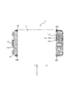
- FIG. 5 is a cross-sectional view taken along the line BB of FIG. 3;
- 1 is a block diagram showing an example of a schematic configuration of a communication apparatus according to an embodiment. It is a graph which shows the change of the electromagnetic wave transmission strength of a communication module. It is a flowchart which shows an example of the procedure which controls a communication apparatus. It is a figure which shows typically operation
- the communication device 1 may typically be a communication device 1 for IoT (Internet of Things).
- the communication device 1 according to the present embodiment is not limited to the communication device 1 for IoT, and may be various communication devices 1 having a wireless communication function.
- the communication device 1 is also simply referred to as a device.
- the communication device 1 may communicate with an external device such as an external server.
- the communication device 1 may acquire information on the external environment.
- the communication device 1 may transmit the acquired external environment information to an external server or the like.
- the communication device 1 may be used in a state of being attached to another device or a product or a cargo. As the communication device 1 is miniaturized, it becomes easy to be attached to another device, goods, cargo or the like.
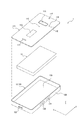
- the communication device 1 may include a housing 10 and an internal structure 13.
- the internal structure 13 may be located inside the housing 10.
- the housing 10 may include a plate 11 and a case 12.
- the housing 10 can protect the internal structure 13.
- the housing 10 may further include a packing for sealing between the plate 11 and the case 12. By sealing the space between the plate 11 and the case 12 with packing, moisture, dust and the like are less likely to intrude into the inside of the housing 10. As a result, the internal structure 13 is easily protected from moisture or dust.
- the external shape of the housing 10 may be a rectangular parallelepiped having sides along the X axis, the Y axis, and the Z axis which intersect with each other.
- the X, Y and Z axes may be orthogonal to one another.
- the length in the X-axis direction of the housing 10 is longer than the length in the Y-axis direction of the housing 10 and the length in the Z-axis direction of the housing 10.
- the length in the Y-axis direction of the housing 10 is longer than the length in the Z-axis direction of the housing 10.
- the X-axis direction is also referred to as a first direction.
- the Y-axis direction is also referred to as a second direction.
- the Z-axis direction is also referred to as a third direction.
- the length in the first direction of the housing 10 is longer than the length in the second direction and the length in the third direction.
- the first direction, the second direction, and the third direction are also referred to as the longitudinal direction, the short direction, and the thickness direction of the housing 10, respectively.
- the housing 10 may be made of a material having a strength that can withstand the use environment according to the application of the communication device 1.
- the housing 10 may be made of resin or metal.
- the plate 11 may have a switch handle 11A and a notification window 11B.
- the switch handle 11A is disposed corresponding to the switch 81 (see FIG. 3) included in the internal structure 13. By doing this, the user can operate the switch 81 via the switch handle 11A.
- the switch handle 11A may be made of a flexible material.
- the notification window 11B is arranged corresponding to the notification unit 80 (see FIG. 3) included in the internal structure 13.
- the notification window 11B may be made of a transparent member or the like. By doing this, the user can visually recognize the notification unit 80 through the notification window 11B.
- the plate 11 may further have a hole 11C, a hole 11D, a hole 11E and a hole 11F.
- 11 C of holes are arrange
- the holes 11D are arranged corresponding to the temperature sensor 72 (see FIG. 3) included in the internal structure 13.
- the holes 11E are disposed corresponding to the humidity sensor 73 (see FIG. 3) included in the internal structure 13.
- the holes 11F are arranged corresponding to the illuminance sensor 74 (see FIG. 3) included in the internal structure 13.
- the atmospheric pressure sensor 71, the temperature sensor 72, the humidity sensor 73, and the illuminance sensor 74 are collectively referred to as a sensor 70 (see FIG. 3). Each sensor 70 can detect the environment outside the housing 10 with higher accuracy.
- the case 12 may have a bottom 12A and a side 12B.
- the bottom portion 12A is located on the opposite side of the plate 11 with the internal structure 13 interposed therebetween.
- the side surface portion 12B is located between the plate 11 and the bottom surface portion 12A, and intersects the bottom surface portion 12A and the plate 11.
- the case 12 may have insertion ports 12C, 12D and 12E in the side surface portion 12B.
- the insertion ports 12C and 12D may be disposed corresponding to the external terminals 22 and 23 (see FIG. 3) included in the internal structure 13. By doing this, the terminals of the external device can be connected to the external terminals 22 and 23 through the insertion ports 12C and 12D.
- the insertion port 12E is disposed corresponding to the slot 24 (see FIG. 3) included in the internal structure 13. By doing this, a SIM (Subscriber Identity Module) card or the like can be inserted into the slot 24 through the insertion port 12E.
- SIM Subscriber Identity Module
- At least one of the holes 11C to 11F and the notification window 11B may be disposed on the side surface 12B of the case 12.
- the plate 11 may further have marks 11G.
- the mark 11 ⁇ / b> G may be, for example, a logo mark or the like representing a main body of the communication device 1.
- the user can specify the orientation of the communication device 1 based on the position of the mark 11G. For example, when disposing the communication device 1 on the ground or the like, the user may arrange the communication device 1 so that the side of the plate 11 does not contact the ground or the like. That is, the user can arrange the communication device 1 such that the bottom surface 12A of the case 12 contacts the ground or the like. When the side of the plate 11 is not in contact with the ground or the like, the holes 11C to 11F and the notification window 11B are less likely to be blocked by the ground or the like.
- the communication device 1 When the holes 11C to 11F and the notification window 11B are disposed on the side surface portion 12B of the case 12, the communication device 1 is disposed such that the bottom surface portion 12A of the case 12 contacts the ground or the like. And notification window 11B becomes difficult to be closed by the ground etc.
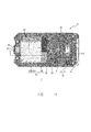
- the internal structure 13 includes an antenna 100 and a communication module 50.
- the internal structure 13 may further include an external terminal 22.
- the internal structure 13 may further include a circuit board 20.
- Internal structure 13 may further include a battery 30.
- Internal structure 13 may further include a frame 40.
- the internal structure 13 may further include a sensor 70, a notification unit 80, and a switch 81.
- the antenna 100 may be located on the side of the housing 10 in the positive direction of the X axis. At least one of the communication module 50 and the external terminal 22 may be located on the negative side of the X axis in the housing 10. That is, the antenna 100 may be located on one end side of the housing 10 in the first direction. At least one of the communication module 50 and the external terminal 22 may be located on the other side of the housing 10 in the first direction. The antenna 100 and at least one of the communication module 50 and the external terminal 22 may be located opposite to each other along the first direction.
- the antenna 100 is separated from the predetermined distance from at least one of the communication module 50 and the external terminal 22 which can be noise sources of radio waves, thereby receiving the influence of the noise sources when radio waves are received. It becomes difficult to receive. As a result, the convenience of the communication device 1 can be enhanced. It is more effective in the communication apparatus 1 for IoT, which is required to be smaller in size than a mobile phone such as a smartphone in many cases and is concerned about the influence of noise sources.
- a plurality of external terminals 22 are provided, if at least one external terminal 22 is located on the opposite side to the antenna 100 along the first direction, an effect of reducing the influence of noise sources can be obtained.
- the circuit board 20 may be plate-shaped.
- the circuit board 20 may be located along the XY plane.
- the circuit board 20 may be made of a material such as resin or ceramic.
- Various components may be mounted on the circuit board 20.
- the components mounted on the circuit board 20 may include, for example, an electronic component 60 (see FIG. 9), a sensor 70, or a notification unit 80 or the like. Terminals or wires may be mounted on the circuit board 20.
- the battery terminal 21 and the external terminal 22 may be mounted on the surface of the circuit board 20 on the negative direction side of the Z axis.
- Battery terminal 21 includes a battery terminal 21A connected to the positive terminal of battery 30, a battery terminal 21B for detecting the remaining amount of battery 30, and a battery terminal 21C connected to the negative terminal of battery 30.
- the battery terminal 21 may have a biasing mechanism that biases the battery 30.
- the battery terminal 21 may bias the battery 30 in the negative direction of the X axis.
- the external terminal 22 is fixed to the circuit board 20 by the support 22A.
- the external terminal 22 is a terminal to which an external device can be connected.
- the external terminal 22 may be, for example, a terminal to which a micro USB (Universal Serial Bus) connector can be connected.
- the communication device 1 may be controlled by an external device connected via the external terminal 22.
- the communication device 1 may charge the battery 30 with the power supplied from the external terminal 22.
- the external terminal 23 may be a terminal corresponding to a universal asynchronous receiver / transmitter (UART) which is a type of circuit for converting a signal.
- UART universal asynchronous receiver / transmitter
- a terminal corresponding to the UART can be used, for example, to connect to a sensor 70 provided outside the communication device 1.
- SIM card may be inserted into the slot 24.
- the slot 24 may be inserted with another card such as a memory card.
- the battery 30 may supply power to each component of the communication device 1.
- the battery 30 may include a rechargeable secondary battery.
- the secondary battery may include, for example, a lithium ion battery, a nickel cadmium battery, or a nickel hydrogen battery.
- the battery 30 is not limited to a secondary battery, and may include a primary battery that can not be charged.
- the primary battery may include, for example, an alkaline battery or a manganese battery.
- the frame 40 may hold the circuit board 20 and the battery 30.
- the frame 40 may house the circuit board 20 and the battery 30 therein.
- the circuit board 20, the battery 30, and the frame 40 may be integrated. By integrating the circuit board 20, the battery 30, and the frame 40, the strength of the internal structure 13 can be enhanced.
- the frame 40 may have a body 41.
- the main body 41 may have a flat portion 41A facing in the positive direction of the Z axis and side portions facing in the positive and negative directions of the Y axis.
- the flat portion 41A may be located on the positive side of the Z axis.
- the flat portion 41A may be in the form of a plate extending along the XY plane.
- the side surface portion may project from the periphery of the flat surface portion 41A in the negative direction of the Z axis. It can be said that the main body 41 has an opening surrounded by the side surface on the negative direction side of the Z axis.
- the main body 41 may accommodate the circuit board 20 and the battery 30 from the side of the opening.
- the frame 40 may have holding portions 42A and 42B and convex portions 45A and 45B.
- the holding portions 42A and 42B may be positioned at two corners located on the positive direction side of the X axis of the battery 30.
- the holding portions 42A and 42B may further protrude from the side surface of the main body 41 to the negative side of the Z axis.
- the shape of the holding portions 42A and 42B viewed from the Y-axis direction may be L-shaped.
- the tips of the holding portions 42A and 42B may project in the negative direction side of the X axis so as to hold the battery 30 on the negative direction side of the Z axis.
- the shape of the holding portions 42A and 42B viewed from the Y-axis direction is not limited to the L shape, and may be any shape that can hold the battery 30.
- the convex portions 45A and 45B may be positioned at two corners located on the negative side of the X axis of the battery 30.
- the protrusions 45A and 45B may further protrude from the side surface of the main body 41 to the negative side of the Z axis.
- the protrusions 45A and 45B can abut on the end of the battery 30 on the negative direction side of the X axis when, for example, a force is applied to the battery 30 from the positive direction of the X axis. By doing this, even if the battery 30 moves in the negative direction of the X axis, it becomes difficult to collide with the support 22A. As a result, the impact on the support 22A can be reduced.
- the protrusions 45A and 45B may support the battery 30 biased in the negative direction of the X axis when the battery terminal 21 has a biasing mechanism.
- the battery 30 may be sandwiched between the battery terminal 21 and the protrusions 45A and 45B.
- the frame 40 may have a frame opening 46.
- the frame opening 46 may be an opening located in a part of the plate-like member of the main body 41.
- the frame opening 46 may be located corresponding to the position where the communication module 50 is mounted.
- Each component of the frame 40 may, for example, comprise a material of appropriate strength.
- Materials of suitable strength may include, for example, resins or metals.
- Each component of the frame 40 may be integrally formed of a material of appropriate strength. By integrally forming the components of the frame 40, the strength of the frame 40 can be enhanced. As a result, it is difficult to transmit an external impact to the internal structure 13.
- the communication module 50 may be mounted at a position corresponding to the frame opening 46 of the frame 40 on the surface on the positive direction side of the Z axis of the circuit board 20, as shown in FIG.
- the communication module 50 may include side walls extending towards the circuit board 20.
- the side wall portion may be a shield case, or may be another member.
- the side wall can receive a force applied to the internal structure 13 from the positive direction of the Z axis. By doing this, the force applied to the communication module 50 can be reduced. As a result, the communication module 50 is less likely to be deformed.
- the communication module 50 may be mounted on the surface of the circuit board 20 on the positive direction side of the Z axis via the communication circuit board 51 different from the circuit board 20.
- the communication circuit board 51 may be made of, for example, a material such as ceramic.
- the communication circuit board 51 may be plate-shaped.
- the communication circuit board 51 and at least a part of the surface on the positive direction side of the Z axis of the battery 30 may be opposed to each other with the circuit board 20 interposed therebetween.
- the communication circuit board 51 and the circuit board 20 contain different materials, the amount of bending of the communication circuit board 51 and the circuit board 20 due to an external force may be different.
- the communication circuit board 51 may have a cavity 52 on the side facing the circuit board 20.
- a part of the electronic component 60 may be mounted inside the cavity 52.
- a portion of the electronic component 60 mounted inside the cavity 52 may be a component not related to communication.
- the electronic component 60 includes, for example, a storage unit 61 and a control unit 62.
- the storage unit 61 and the control unit 62 may be mounted inside the cavity 52.
- the electronic component 60 may include a communication unit or the like.
- the electronic component 60 may be mounted on the circuit board 20 or may be mounted on the surface of the communication circuit board 51 on which the cavity 52 is formed. By mounting the electronic component 60 in the cavity 52, a gap can be formed between the electronic component 60 and the circuit board 20. By doing this, it is difficult to transmit the shock resulting from the deformation of the circuit board 20 to the electronic component 60. As a result, the electronic component 60 can be protected.
- the cavity 52 and at least a part of the surface on the positive direction side of the Z axis of the battery 30 may be opposed to each other with the circuit board 20 interposed therebetween.
- the external force is easily absorbed by the battery 30 having high rigidity, and becomes difficult to be transmitted to the communication circuit board 51.
- deformation of the communication circuit board 51 can be reduced, and the electronic component 60 in the cavity 52 is less likely to be damaged.
- the sensor 70 may include, for example, at least one of an atmospheric pressure sensor 71, a temperature sensor 72, a humidity sensor 73, and an illuminance sensor 74 in order to obtain information on the external environment.
- the sensor 70 may include, for example, at least one of an acceleration sensor, an angular velocity sensor, and a geomagnetic sensor, in order to obtain information on at least one of the position, movement, and attitude of the sensor 70 itself.
- the angular velocity sensor can detect the angular velocity of the device or the like in which the sensor 70 is provided.
- the acceleration sensor can detect an acceleration occurring in a device or the like in which the sensor 70 is provided.
- the geomagnetic sensor can detect the direction of geomagnetism.
- the sensor 70 may include a position sensor.
- the position sensor may detect position information of an apparatus or the like provided with the sensor 70 based on a detection result of a radio wave of near field communication such as RFID (Radio Frequency Identifier).
- the notification unit 80 may be mounted at a position corresponding to the notification window 11B (see FIG. 1).
- the notification unit 80 may include, for example, a light emitting device such as a light emission diode (LED).
- the notification unit 80 may include another light emitting device.
- the notification unit 80 may turn on the light emitting device based on the control of the control unit 62.
- Various pieces of information notified by the notification unit 80 to the user may be associated with the lighting color of the light emitting device or the lighting pattern.
- the notification unit 80 may notify the user that the power of the communication device 1 is in the on state by lighting the light emitting device green.
- the notification unit 80 may notify the user that the communication device 1 is in communication with an external device or the like by keeping the light emitting device turned on.
- the notification unit 80 may notify that the remaining amount of the battery 30 is below the predetermined value by blinking the light emitting device.
- the notification unit 80 may include, for example, a display device such as an LCD (Liquid Crystal Display).
- the notification unit 80 may include another display device.
- the notification unit 80 may cause the display to display various types of information to be notified to the user based on the control of the control unit 62.
- the switch 81 may be mounted at a position corresponding to the switch handle 11A (see FIG. 1).
- the switch 81 can be operated by the user via the switch handle 11A.
- the operation by the user input to the switch 81 may be output to the control unit 62.
- the control unit 62 may execute a predetermined function associated with the operation of the switch 81.
- the predetermined function may include a function of causing the communication device 1 to transition between a power-on state and a power-off state.
- the predetermined function may include a function of starting or stopping the operation of the communication device 1.
- the control unit 62 may execute different functions based on the number of times the switch 81 is pressed.
- the control unit 62 may perform different functions based on the length of time when the switch 81 is pressed.
- the antenna 100 may be located along the outer surface of the main body 41 of the frame 40.
- the antenna 100 may be located on the side of the plane portion 41A of the main body 41 in the positive direction of the Z axis. That is, the antenna 100 may be located on the side opposite to the side on which the circuit board 20 and the battery 30 are held in the frame 40. In this way, when the battery 30 having a relatively heavy mass is located closer to the ground or the like, the antenna 100 can be located farther from the ground or the like. As a result, when the antenna 100 transmits and receives radio waves, the influence of noise and the like from the ground can be reduced.
- the antenna 100 may be electrically connected to the communication module 50.
- the communication module 50 may wirelessly communicate with an external device by acquiring a radio wave received by the antenna 100 or transmitting the radio wave to the antenna 100.
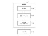
- the communication device 1 includes a communication module 50, a control unit 62, and an antenna 100.
- the control unit 62 is also referred to as a controller.
- the controller 62 may be connected to the sensor 70.
- the sensor 70 may be provided in the communication device 1 or may be provided as an external device different from the communication device 1. When the sensor 70 is provided as an external device, the sensor 70 may be connected via the external terminal 23.
- the communication module 50 can realize various functions including wireless communication.
- the communication module 50 may realize communication based on Low Power Wide Area (LPWA) technology.
- the communication module 50 may realize communication by various communication methods such as LTE (Long Term Evolution).
- the communication module 50 may wirelessly communicate with an external device via the antenna 100.
- Communication module 50 may include at least one processor.
- the communication module 50 is also referred to as a communication device.
- the communication module 50 may acquire position information of the communication device 1 based on GNSS (Global Navigation Satellite System) technology or the like. That is, the communication module 50 may be able to obtain position information of the own device.
- GNSS technology may include satellite positioning systems such as GPS (Global Positioning System), GLONASS, Galileo, Quasi-Zenith Satellite (QZSS) and the like.
- the position information of the communication device 1 may include latitude, longitude, and altitude information.
- the communication device 1 may obtain information on the position of the own device by the other components of the communication module 50.
- the communication module 50 may be mountable in an apparatus for acquiring information on the position of the own device.
- the controller 62 includes at least one processor to provide control and processing capabilities to perform various functions.
- the processor may be implemented as a single integrated circuit.
- the integrated circuit is also referred to as an integrated circuit (IC).
- the processor may be implemented as a plurality of communicatively coupled integrated circuits and discrete circuits.
- the processor may be implemented based on various other known techniques.
- the communication device 1 may further include a storage unit 61 connected to the control unit 62.
- the storage unit 61 may be configured by a semiconductor memory, a magnetic memory, or the like.
- the storage unit 61 stores various information, programs executed by the control unit 62, and the like.
- the storage unit 61 may function as a work memory of the control unit 62.
- the storage unit 61 may be included in the control unit 62.
- the antenna 100 may be electrically connected to the communication module 50.
- the communication module 50 may wirelessly communicate with an external device such as an external server by acquiring a radio wave received by the antenna 100 or transmitting a radio wave from the antenna 100.
- the communication device 1 may transmit the detection result of the sensor 70 or position information of the communication device 1 to an external device.
- the control unit 62 may transmit the detection result of the sensor 70 or the position information of the communication device 1 to the external device via the communication module 50.
- the communication module 50 may cause the antenna 100 to transmit a radio wave having a predetermined strength.
- the predetermined strength may be determined as appropriate.
- the communication module 50 may transmit a radio wave from the antenna 100 based on the control information acquired from the control unit 62.
- the communication module 50 may have, for example, a function included in Release 13 specification of 3 rd Generation Partnership Project (3GPP) or the like.
- the 3GPP Release 13 specifications include functions supported by a UE (User Equipment) category M1 and functions supported by an NB-IoT (Narrow Band IoT) category.
- the communication module 50 may transmit and receive radio waves from the antenna 100 based on the DRX (Discontinuous Reception) technology defined in the 3GPP specifications.
- the DRX technology may include eDRX (extended DRX) technology.
- the DRX technology is a technology that can reduce the power consumption of the communication module 50 by causing the communication module 50 to intermittently receive radio waves.
- the operation based on the DRX technology is also referred to as intermittent reception operation.
- the communication module 50 can realize intermittent transmission and reception of radio waves by stopping transmission and reception of radio waves for a predetermined period.
- the predetermined period for stopping transmission and reception of radio waves based on the DRX technology is also referred to as a DRX sleep period.
- the communication module 50 may start PSM (Power Saving Mode), which is a function capable of reducing the power consumption of the communication device 1 itself, based on the control information acquired from the control unit 62.
- the communication module 50 may initiate a PSM as defined in the 3GPP specifications.
- the communication module 50 may start PSM based on control information acquired from an external device such as an external server.
- PSM is also referred to as a power saving mode of communication. That is, the control unit 62 may cause the communication module 50 to start PSM.
- the communication device 1 itself is also called an own device.
- the period until the communication module 50 starts PSM and ends PSM is also referred to as PSM period.
- the communication module 50 stops transmission and reception of radio waves for a predetermined period in the PSM period.
- the communication module 50 After stopping transmission and reception of radio waves for a predetermined period, the communication module 50 performs transmission and reception of radio waves for confirming that the communication module 50 is operating.
- the predetermined period in which the communication module 50 does not transmit radio waves in the PSM period is also referred to as a PSM sleep period.
- the PSM sleep period may be set longer than the DRX sleep period.
- the horizontal axis represents time.
- the vertical axis represents the intensity of the radio wave transmitted by the communication module 50.
- the vertical bar tm represents the timing of transmission and reception of radio waves. That is, the communication module 50 may transmit and receive radio waves at the timing corresponding to the time specified by the vertical bar tm.
- the communication module 50 may start PSM at a time represented by T1 and may end PSM at a time represented by T2. That is, the period from the time represented by T1 to the time represented by T2 may be a PSM period represented by D1.
- the communication module 50 may stop transmission and reception of radio waves during a PSM sleep period represented by P1 in the PSM period.
- the communication module 50 may perform the intermittent reception operation in a period until the time represented by T1 or in a period after the time represented by T2.
- the communication module 50 may stop transmission and reception of radio waves during a DRX sleep period represented by P2 when performing the intermittent reception operation.
- the power consumption of the communication module 50 during the PSM sleep period may be reduced to the same extent as the power consumption when the communication module 50 is powered off. That is, when the communication module 50 starts PSM, the power consumption of the communication module 50 can be reduced without the power supply of the communication module 50 being turned off. If the communication module 50 is simply turned off, the operation of the communication module 50 is difficult to confirm. On the other hand, when the communication module 50 starts PSM, the operation of the communication module 50 can be easily confirmed by the communication module 50 transmitting and receiving radio waves each time the PSM sleep period elapses. That is, when the communication module 50 starts PSM, both the confirmation of the operation of the communication module 50 and the reduction of the power consumption of the communication module 50 can be compatible.
- the communication module 50 may start PSM when the position of the own device is within a predetermined range.
- the communication module 50 may start PSM when the own device enters the predetermined range. That is, the communication module 50 may start PSM when its own device enters a predetermined range.
- the predetermined range may be a range in which transmission of communication radio waves is limited.
- the range in which the transmission of the communication radio wave is limited may be a place where the use of the communication device 1 is not preferable.
- the power consumption by the communication module 50 can be automatically reduced by the communication module 50 starting PSM based on the position of the own device. As a result, the convenience of the communication device 1 and the communication module 50 can be improved.
- the range in which the transmission of the communication radio wave is limited may be, for example, the inside of the aircraft or around the runway of the airport where the aircraft departs and arrives.
- the range in which the transmission of the communication radio wave is limited may be in a building such as a hospital or a clinic. By restricting transmission of communication radio waves in a building such as a hospital or a clinic, the influence of communication radio waves on medical equipment and the like can be reduced.
- the range in which the transmission of the communication radio wave is limited may be in a site such as a school or in a building such as a music hall.
- noise that may be generated when the user uses the communication device 1 can be reduced. As a result, silence in a school, a music hall, or a hospital or clinic can be easily maintained.
- Beacon signals may be transmitted at various locations such as airports, schools, hospitals or clinics, or music halls.
- the beacon signal may include information identifying the source of the signal or its location.
- the communication module 50 may obtain information on the position of the own device by receiving the beacon signal. That is, reception of a beacon signal may correspond to acquisition of information on the position of the own aircraft.
- the communication module 50 may determine that the own device is located within the predetermined range based on the reception result of the beacon signal.
- the communication module 50 may initiate PSM upon receiving a beacon signal. Even if it is difficult for the communication module 50 to receive control information regarding the start of PSM from an external server or the like, the communication module 50 can start PSM based on the reception of the beacon signal. As a result, initiation of PSM by the communication module 50 can be performed more reliably. By starting the PSM based on the reception of the beacon signal by the communication module 50, the communication module 50 can continue the communication without starting the PSM until the timing as close as possible to the timing when the period to stop the communication starts. it can. When the communication device 1 is carried by the user, the period of keeping track of the position of the user may be extended. When the communication device 1 is attached to a cargo or the like, the period of keeping track of the position of the cargo or the like can be extended. As a result, the convenience of the communication device 1 and the communication module 50 can be improved.
- the control unit 62 can cause the communication module 50 to start PSM based on control information received from an external device such as an external server. In other words, the communication module 50 may start PSM based on control information received from an external device. On the other hand, the control unit 62 can cause the communication module 50 to start PSM even if it is not based on control information received from an external device. In other words, the communication module 50 can start PSM even if it is not based on control information received from an external device. Since the PSM can be started based on the control information received from the external device, the start of the PSM by the communication module 50 can be performed more reliably regardless of whether the communication status with the outside is good or not. That is, the configuration in which PSM can be started without being based on control information received from an external device can function as a fail safe when the communication status with the outside is not good.
- the communication module 50 may end PSM in a PSM period based on a predetermined condition.
- the predetermined condition for the communication module 50 to end PSM is also referred to as a PSM end condition.
- the PSM termination condition may be, for example, that a predetermined time has elapsed from the start of PSM.
- the communication module 50 may measure the elapsed time from the start of PSM using a timer, and may end PSM when the elapsed time becomes equal to or longer than a predetermined time.
- the timer may be included in the communication module 50 or may be provided outside the communication module 50.
- the predetermined time to be compared with the elapsed time from the start of PSM is also referred to as a first set time.
- the first set time may be set appropriately.
- the first set time may be determined based on, for example, a flight plan of the aircraft.
- the first set time may be determined based on, for example, a prediction of time spent in a hospital or clinic, a school or a music hall, or the like.
- the PSM termination condition may be to acquire control information on termination of PSM from the control unit 62. That is, the control unit 62 may cause the communication module 50 to end PSM. The control unit 62 may cause the communication module 50 to end the PSM based on, for example, the detection result acquired from the sensor 70. The control unit 62 may cause the communication module 50 to end the PSM when the detection result acquired from the sensor 70 satisfies the predetermined condition. The control unit 62 may cause the communication module 50 to end the PSM based on the information acquired from another module such as an RFID module. Further, when the communication apparatus 1 includes another module different from the communication module 50 and performs wireless communication such as IEEE 802.11 or Bluetooth (registered trademark), the control unit 62 uses information acquired from the other module. Based on the communication module 50 may terminate the PSM. The control unit 62 may cause the communication module 50 to end the PSM based on the user's operation on the switch 81.
- the PSM termination condition is not limited to these conditions, and may be other various conditions.
- the communication module 50 terminates the PSM even if it is difficult to obtain the position information of the own device by stopping transmission and reception of radio waves. Can be determined. As a result, the convenience of the communication device 1 and the communication module 50 can be improved.
- the communication module 50 of the communication device 1 may stop the function of acquiring information regarding the position of the own device during the PSM period.
- the control unit 62 may end the PSM based on the information acquired by the function different from the function of acquiring the information on the position of the own device.
- the function of acquiring information on the position of the own machine is a function of acquiring information on the position of the own machine based on GNSS technology or the like.
- the different functions may be the function of acquiring the detection result of the sensor 70, the function of acquiring information from the RFID module, and the function of detecting the user's operation as described above.
- the function of acquiring information related to the position of the own device may be stopped based on GNSS technology etc., but the communication module 50 according to one embodiment more reliably terminates PSM even in such a case. can do.
- the stop means that during transmission and reception of radio waves for confirming that the communication module 50 is operating during the PSM period, although information on the position of the own device can be acquired, except for the transmission and reception, it is basic In some cases, this includes cases where it is not possible to provide information on the position of the aircraft.
- the communication device 1 may start PSM based on information acquired by a specific function of the communication module 50.
- the communication device 1 may stop at least a part of the functions including the specific function of the communication module 50 in the PSM period.
- the communication device 1 may end the PSM based on the information acquired by the control unit 62 without passing through the communication module 50.
- the specific function may be, for example, a function of acquiring information on the position of the own machine.
- the specific function may be, for example, a function of acquiring information on the position of the own machine.
- the specific function may be a function that communicates with an external device such as an external server and receives control information that is a trigger for starting PSM.
- the information acquired by the control unit 62 without passing through the communication module 50 may be information acquired by the sensor 70 or the RFID module.
- the information acquired by the control unit 62 without passing through the communication module 50 may be information resulting from the user's operation.
- the communication module 50 according to an embodiment can more reliably terminate the PSM even in such a case. Stopping means that at least a part of the function of the communication module 50 can be executed when transmitting and receiving radio waves for confirming that the communication module 50 is operating in the PSM period, except for this. In principle, this also includes the case where some of the functions are not performed.
- the control unit 62 is a processor (main control unit) that controls the entire communication device 1 and a co-processor that partially controls functional units that configure the communication device 1 (sub control And may be composed of
- the communication device 1 may stop at least a part of functions of the processor in the PSM period, and may end the PSM based on the information acquired by the co-processor.
- the co-processor may be a sensor microcomputer.
- the information acquired by the co-processor may be the detection result of the sensor 70.
- the communication module 50 may start PSM immediately when the position of the own device enters a predetermined range.
- the communication module 50 may start PSM after a predetermined time has elapsed since the position of the own device enters a predetermined range.
- the communication module 50 may measure the elapsed time after the position of the own device has entered the predetermined range by the timer, and may start PSM when the elapsed time becomes equal to or longer than the predetermined time.
- the predetermined time to be compared with the elapsed time after the position of the own machine enters the predetermined range is also referred to as a second set time. That is, the communication module 50 may start PSM after the second set time has elapsed in response to the position of the own device entering the predetermined range.
- the second set time may be set appropriately.
- the second set time may be determined, for example, based on the flight plan of the aircraft.
- the second set time may be determined based on, for example, the opening time of a school, the opening time of an event in a music hall, or the like.
- the communication module 50 may extend the DRX sleep time when the position of the own device falls within a predetermined range. By doing this, the power consumption by the communication module 50 can be reduced. As a result, the convenience of the communication device 1 and the communication module 50 can be improved.
- the communication device 1 may control communication according to the procedure of the flowchart illustrated in FIG.
- the control unit 62 acquires position information of the own machine (step S11). That is, the control unit 62 acquires position information of the communication device 1 itself.
- the control unit 62 may obtain position information of the own device from the communication module 50.
- the control unit 62 may acquire the position information of the own machine detected by the sensor 70.
- the control unit 62 determines whether the position of the own device is within the predetermined range based on the position information of the own device (step S12).
- the predetermined range may be set, for example, around the runway of the airport.
- the predetermined range may be set at a site such as a school or a hospital.
- the predetermined range may be set inside a building such as a music hall.
- the predetermined range is not limited to these, and may be set to various ranges.
- step S12 When the position of the own device is not within the predetermined range (step S12: NO), the control unit 62 returns to step S11. Control part 62 makes communications module 50 start PSM, when a position of an own machine is in a predetermined range (Step S12: YES) (Step S13).
- the control unit 62 causes the communication module 50 to end PSM based on the predetermined condition (step S14). After step S14, the control unit 62 ends the procedure of the flowchart of FIG.
- the communication device 1 can be carried by a child 2 or a student as schematically shown in FIGS. 9 and 10.
- the position information of the own device acquired by the communication device 1 may be transmitted to the terminal owned by the parent, and the parent may confirm the position of the child 2 or the student.
- the communication device 1 does not start PSM, for example, operates based on the DRX technology. May be running.
- the communication device 1 may have started PSM.
- the communication device 1 receives a beacon signal transmitted at a school gate of school 3 or at an entrance of a school building, whereby a child 2 or a student carrying his / her own machine is at the entrance of the school gate of school 3 or a school building. It may detect that it has passed. The communication device 1 may detect that a child 2 or a student carrying his own device has passed through the school entrance or the entrance of the school 3 by another method.
- each functional unit can be rearranged so as not to be logically contradictory.
- a plurality of functional units may be combined or divided into one.
- Each embodiment according to the present disclosure described above is not limited to be implemented faithfully to each described embodiment, and may be implemented by combining the respective features or omitting some of them as appropriate. .
- Reference Signs List 1 communication device 2 student 3 school 10 housing 11 plate 11A switch handle 11B notification window 11C, 11D, 11E, 11F hole 11G mark 12 case 12A bottom part 12B side part 12C, 12D, 12E socket 13 internal structure 20 circuit board 21 (21A, 21B, 21C) Battery terminal 22, 23 External terminal 22A Support section 24 Slot 30 Battery 40 Frame 41 Body 41A Flat section 42A, 42B Holding section 45A, 45B Convex section 46 Frame opening 50 Communication module 51 Communication circuit board 52 Cavity 60 electronic component 61 storage unit 62 control unit (controller) 70 sensor 71 barometric pressure sensor 72 temperature sensor 73 humidity sensor 74 illuminance sensor 80 notification unit 81 switch 100 antenna
Landscapes
- Engineering & Computer Science (AREA)
- Signal Processing (AREA)
- Computer Networks & Wireless Communication (AREA)
- Telephone Function (AREA)
- Telephonic Communication Services (AREA)
- Mobile Radio Communication Systems (AREA)
Applications Claiming Priority (2)
| Application Number | Priority Date | Filing Date | Title |
|---|---|---|---|
| JP2017-250169 | 2017-12-26 | ||
| JP2017250169A JP6748631B2 (ja) | 2017-12-26 | 2017-12-26 | 通信装置、通信モジュール、通信方法及び通信プログラム |
Publications (1)
| Publication Number | Publication Date |
|---|---|
| WO2019131337A1 true WO2019131337A1 (ja) | 2019-07-04 |
Family
ID=67067317
Family Applications (1)
| Application Number | Title | Priority Date | Filing Date |
|---|---|---|---|
| PCT/JP2018/046605 Ceased WO2019131337A1 (ja) | 2017-12-26 | 2018-12-18 | 装置、通信機器、通信方法及び通信プログラム |
Country Status (2)
| Country | Link |
|---|---|
| JP (1) | JP6748631B2 (enExample) |
| WO (1) | WO2019131337A1 (enExample) |
Cited By (1)
| Publication number | Priority date | Publication date | Assignee | Title |
|---|---|---|---|---|
| WO2026038342A1 (ja) * | 2024-08-15 | 2026-02-19 | 本田技研工業株式会社 | 端末装置、プログラム、及び通信制御方法 |
Citations (4)
| Publication number | Priority date | Publication date | Assignee | Title |
|---|---|---|---|---|
| JP2000092568A (ja) * | 1998-09-09 | 2000-03-31 | Nec Mobile Commun Ltd | 移動局の送信制御方式 |
| JP2003008733A (ja) * | 2001-06-26 | 2003-01-10 | Hitachi Electronics Service Co Ltd | 携帯電話機 |
| JP2014120800A (ja) * | 2012-12-13 | 2014-06-30 | Panasonic Corp | 無線通信システム及び携帯情報端末 |
| US20170339640A1 (en) * | 2016-05-18 | 2017-11-23 | Qualcomm Incorporated | Deep sleep mode abort mechanism for machine-type communication devices |
Family Cites Families (2)
| Publication number | Priority date | Publication date | Assignee | Title |
|---|---|---|---|---|
| JP3851554B2 (ja) * | 2001-12-11 | 2006-11-29 | 株式会社日立製作所 | 携帯電話装置を制御する制御方法 |
| JP2014053676A (ja) * | 2012-09-05 | 2014-03-20 | Yoshiji Matsumoto | データ送受信を実行する携帯端末、方法、及びプログラム |
-
2017
- 2017-12-26 JP JP2017250169A patent/JP6748631B2/ja active Active
-
2018
- 2018-12-18 WO PCT/JP2018/046605 patent/WO2019131337A1/ja not_active Ceased
Patent Citations (4)
| Publication number | Priority date | Publication date | Assignee | Title |
|---|---|---|---|---|
| JP2000092568A (ja) * | 1998-09-09 | 2000-03-31 | Nec Mobile Commun Ltd | 移動局の送信制御方式 |
| JP2003008733A (ja) * | 2001-06-26 | 2003-01-10 | Hitachi Electronics Service Co Ltd | 携帯電話機 |
| JP2014120800A (ja) * | 2012-12-13 | 2014-06-30 | Panasonic Corp | 無線通信システム及び携帯情報端末 |
| US20170339640A1 (en) * | 2016-05-18 | 2017-11-23 | Qualcomm Incorporated | Deep sleep mode abort mechanism for machine-type communication devices |
Cited By (1)
| Publication number | Priority date | Publication date | Assignee | Title |
|---|---|---|---|---|
| WO2026038342A1 (ja) * | 2024-08-15 | 2026-02-19 | 本田技研工業株式会社 | 端末装置、プログラム、及び通信制御方法 |
Also Published As
| Publication number | Publication date |
|---|---|
| JP2019117980A (ja) | 2019-07-18 |
| JP6748631B2 (ja) | 2020-09-02 |
Similar Documents
| Publication | Publication Date | Title |
|---|---|---|
| US11244559B2 (en) | Multi-sensor electronic device with wireless connectivity and sensing as a service platform and web application | |
| TW201537528A (zh) | 通信裝置及試驗裝置 | |
| US20190129470A1 (en) | Mobile electronic device | |
| US20240395150A1 (en) | Smart frame for vehicle registration plate and related system and methods | |
| US20210095961A1 (en) | Inertial Measurement Unit | |
| CN207067409U (zh) | 一种无人机残骸寻回装置 | |
| CN205334526U (zh) | 一种智能电子学生证 | |
| JP6748631B2 (ja) | 通信装置、通信モジュール、通信方法及び通信プログラム | |
| JP6730250B2 (ja) | 通信装置、通信モジュール、通信方法及び通信プログラム | |
| WO2019131146A1 (ja) | 装置、通信機器、及び通信方法 | |
| US20260127406A1 (en) | Reading device | |
| KR20220090074A (ko) | 응급 상황 알림용 비콘 및 시스템 | |
| EP3487080B1 (en) | Radio equipment which improves the sensitivity of the near field communication | |
| CN216217944U (zh) | 智能穿戴设备及其壳体结构 | |
| JP7045229B2 (ja) | 通信装置 | |
| JP2017026370A (ja) | 電子機器 | |
| US20120244799A1 (en) | Circuit arrangement, communication device, and communication system | |
| WO2019131150A1 (ja) | 装置、通信機器、及び通信方法 | |
| CN118463954B (zh) | 指南针校准方法和电子设备 | |
| JP6987683B2 (ja) | 通信装置、通信装置の制御方法、及び通信装置の制御プログラム | |
| WO2019131151A1 (ja) | 装置、通信機器、及び通信方法 | |
| JP2017026476A (ja) | 電子機器 | |
| CN210955143U (zh) | 一种电子标签 | |
| JP2012190598A (ja) | 情報処理装置 | |
| JP6925934B2 (ja) | 通信ユニット |
Legal Events
| Date | Code | Title | Description |
|---|---|---|---|
| 121 | Ep: the epo has been informed by wipo that ep was designated in this application |
Ref document number: 18896129 Country of ref document: EP Kind code of ref document: A1 |
|
| NENP | Non-entry into the national phase |
Ref country code: DE |
|
| 122 | Ep: pct application non-entry in european phase |
Ref document number: 18896129 Country of ref document: EP Kind code of ref document: A1 |