WO2019131227A1 - Power control device, power control method, and program - Google Patents
Power control device, power control method, and program Download PDFInfo
- Publication number
- WO2019131227A1 WO2019131227A1 PCT/JP2018/046183 JP2018046183W WO2019131227A1 WO 2019131227 A1 WO2019131227 A1 WO 2019131227A1 JP 2018046183 W JP2018046183 W JP 2018046183W WO 2019131227 A1 WO2019131227 A1 WO 2019131227A1
- Authority
- WO
- WIPO (PCT)
- Prior art keywords
- power
- power storage
- priority
- storage systems
- storage system
- Prior art date
Links
Images


Classifications
-
- H—ELECTRICITY
- H02—GENERATION; CONVERSION OR DISTRIBUTION OF ELECTRIC POWER
- H02J—CIRCUIT ARRANGEMENTS OR SYSTEMS FOR SUPPLYING OR DISTRIBUTING ELECTRIC POWER; SYSTEMS FOR STORING ELECTRIC ENERGY
- H02J3/00—Circuit arrangements for ac mains or ac distribution networks
- H02J3/28—Arrangements for balancing of the load in a network by storage of energy
- H02J3/32—Arrangements for balancing of the load in a network by storage of energy using batteries with converting means
-
- H—ELECTRICITY
- H02—GENERATION; CONVERSION OR DISTRIBUTION OF ELECTRIC POWER
- H02J—CIRCUIT ARRANGEMENTS OR SYSTEMS FOR SUPPLYING OR DISTRIBUTING ELECTRIC POWER; SYSTEMS FOR STORING ELECTRIC ENERGY
- H02J7/00—Circuit arrangements for charging or depolarising batteries or for supplying loads from batteries
- H02J7/0013—Circuit arrangements for charging or depolarising batteries or for supplying loads from batteries acting upon several batteries simultaneously or sequentially
-
- H—ELECTRICITY
- H02—GENERATION; CONVERSION OR DISTRIBUTION OF ELECTRIC POWER
- H02J—CIRCUIT ARRANGEMENTS OR SYSTEMS FOR SUPPLYING OR DISTRIBUTING ELECTRIC POWER; SYSTEMS FOR STORING ELECTRIC ENERGY
- H02J7/00—Circuit arrangements for charging or depolarising batteries or for supplying loads from batteries
- H02J7/34—Parallel operation in networks using both storage and other dc sources, e.g. providing buffering
- H02J7/35—Parallel operation in networks using both storage and other dc sources, e.g. providing buffering with light sensitive cells
-
- H—ELECTRICITY
- H02—GENERATION; CONVERSION OR DISTRIBUTION OF ELECTRIC POWER
- H02J—CIRCUIT ARRANGEMENTS OR SYSTEMS FOR SUPPLYING OR DISTRIBUTING ELECTRIC POWER; SYSTEMS FOR STORING ELECTRIC ENERGY
- H02J2300/00—Systems for supplying or distributing electric power characterised by decentralized, dispersed, or local generation
- H02J2300/20—The dispersed energy generation being of renewable origin
- H02J2300/22—The renewable source being solar energy
- H02J2300/24—The renewable source being solar energy of photovoltaic origin
- H02J2300/26—The renewable source being solar energy of photovoltaic origin involving maximum power point tracking control for photovoltaic sources
-
- H—ELECTRICITY
- H02—GENERATION; CONVERSION OR DISTRIBUTION OF ELECTRIC POWER
- H02J—CIRCUIT ARRANGEMENTS OR SYSTEMS FOR SUPPLYING OR DISTRIBUTING ELECTRIC POWER; SYSTEMS FOR STORING ELECTRIC ENERGY
- H02J2310/00—The network for supplying or distributing electric power characterised by its spatial reach or by the load
- H02J2310/10—The network having a local or delimited stationary reach
- H02J2310/12—The local stationary network supplying a household or a building
-
- H—ELECTRICITY
- H02—GENERATION; CONVERSION OR DISTRIBUTION OF ELECTRIC POWER
- H02J—CIRCUIT ARRANGEMENTS OR SYSTEMS FOR SUPPLYING OR DISTRIBUTING ELECTRIC POWER; SYSTEMS FOR STORING ELECTRIC ENERGY
- H02J3/00—Circuit arrangements for ac mains or ac distribution networks
- H02J3/38—Arrangements for parallely feeding a single network by two or more generators, converters or transformers
- H02J3/381—Dispersed generators
-
- Y—GENERAL TAGGING OF NEW TECHNOLOGICAL DEVELOPMENTS; GENERAL TAGGING OF CROSS-SECTIONAL TECHNOLOGIES SPANNING OVER SEVERAL SECTIONS OF THE IPC; TECHNICAL SUBJECTS COVERED BY FORMER USPC CROSS-REFERENCE ART COLLECTIONS [XRACs] AND DIGESTS
- Y02—TECHNOLOGIES OR APPLICATIONS FOR MITIGATION OR ADAPTATION AGAINST CLIMATE CHANGE
- Y02E—REDUCTION OF GREENHOUSE GAS [GHG] EMISSIONS, RELATED TO ENERGY GENERATION, TRANSMISSION OR DISTRIBUTION
- Y02E10/00—Energy generation through renewable energy sources
- Y02E10/50—Photovoltaic [PV] energy
- Y02E10/56—Power conversion systems, e.g. maximum power point trackers
-
- Y—GENERAL TAGGING OF NEW TECHNOLOGICAL DEVELOPMENTS; GENERAL TAGGING OF CROSS-SECTIONAL TECHNOLOGIES SPANNING OVER SEVERAL SECTIONS OF THE IPC; TECHNICAL SUBJECTS COVERED BY FORMER USPC CROSS-REFERENCE ART COLLECTIONS [XRACs] AND DIGESTS
- Y02—TECHNOLOGIES OR APPLICATIONS FOR MITIGATION OR ADAPTATION AGAINST CLIMATE CHANGE
- Y02P—CLIMATE CHANGE MITIGATION TECHNOLOGIES IN THE PRODUCTION OR PROCESSING OF GOODS
- Y02P90/00—Enabling technologies with a potential contribution to greenhouse gas [GHG] emissions mitigation
- Y02P90/50—Energy storage in industry with an added climate change mitigation effect
Definitions
- the present disclosure relates to a power control apparatus that controls power, a power control method, and a program.
- a photovoltaic system may be combined with a storage system.
- the clean mode set in the power system suppresses purchase of electricity from a grid-connected commercial system, and covers the power consumed by the load by power generation by the solar power generation system and discharge of the storage system (see, for example, Patent Document 1) ).
- the present disclosure has been made in view of such circumstances, and an object thereof is to provide a technique for controlling a plurality of power storage systems.
- a power control device that controls charging and discharging of a plurality of power storage systems installed in a customer and connected to a power system.
- a recognition unit that recognizes whether the power is flowing backward from the house to the power system or a forward flow of power from the power system to the consumer, and the recognition unit recognizes that the power is flowing backward
- the control unit is configured to charge at least one power storage system of the plurality of power storage systems based on the priority regarding charging of the plurality of power storage systems.
- the control unit discharges at least one power storage system of the plurality of power storage systems based on the priority regarding discharge of the plurality of power storage systems when recognizing that the recognition unit is in the forward flow state.
- This method is a power control method in a power control apparatus that controls charging and discharging of a plurality of storage systems installed in a consumer and connected to the grid, the reverse flow of power from the consumer to the grid
- the step of recognizing whether it is in the state or in the forward power state of power from the power system to the consumer, and when it is recognized that the power is in the reverse power state priority is given to charging of multiple storage systems.
- a plurality of power storage systems can be controlled.
- FIG. 1 It is a figure which shows the structure of the consumer concerning Example 1.
- FIG. 2 It is a figure which shows the table memorize
- FIG. 1 It is a figure which shows the structure of the consumer concerning Example 2.
- An embodiment relates to a plurality of power storage systems connected to a power system at a consumer.
- the customer is a facility receiving power supply from a power company or the like, and is, for example, a house, an office, a store, a factory, a park, or the like.
- a solar cell system is also installed in the customer, and the solar cell system is connected to the power system and a plurality of storage systems. If the selling price of the power generated in the solar cell system is expensive, the power generated in the solar cell system may be sold by reverse power flow to the power system. On the other hand, if the selling price of the power generated in the solar cell system is low, it is more preferable to supply the load installed to the customer than the selling of the power generated in the solar cell system. The latter case is assumed in this embodiment.
- the power generated by the solar cell system and not consumed by the load is preferably charged to the storage system.
- a storage system supplies power to the load at a timing when the solar cell system is not generating power or at a timing when the power generated by the solar cell system is insufficient.
- the capacity of the storage system is large, one storage system may be installed in the customer. However, in this embodiment, since the capacity of the storage system is not so large, a plurality of storage systems are installed in the customer. When a plurality of power storage systems are installed, unnecessary control may be performed if the respective power storage systems independently control charge and discharge. Therefore, it is desirable to control charging / discharging of a plurality of power storage systems collectively.
- one of the plurality of storage systems is the master storage system, and the remaining is the slave storage system.
- the storage system of the master sets the priority for charging and the priority for discharging for each of the plurality of storage systems.
- the storage system of the master determines whether it is a situation to be charged or discharged in a plurality of storage systems. When it is a condition to be charged, the power storage system of the master selects a power storage system to be charged based on the priority regarding charging, and instructs the selected power storage system to charge. The instructed storage system performs charging. On the other hand, when it is the situation which should be discharged, the storage system of a master performs the same processing based on the priority regarding discharge.
- FIG. 1 shows the configuration of the customer 16.
- the customer 16 includes a power storage system 30, a smart meter 32, a distribution board 34, a load 36, a solar cell system 38, and a first storage system 40a collectively referred to as a storage system 40, a second storage system 40b, and a third storage system.
- 40c, a first outlet 44a, a second outlet 44b, and a third outlet 44c, collectively referred to as an outlet 44, are installed.
- the solar cell system 38 includes PV (Photovoltaics) 200, PV DC (Direct Current) / DC 202, and PV DC / AC (Alternating Current) 204.
- the first power storage system 40a includes a storage battery (SB) 210, a DC / DC 212 for SB, a bidirectional DC / AC inverter 214, a control unit 216, a first communication unit 218, a second communication unit 220, and an operation unit 222.
- the control unit 216 includes a recognition unit 224.
- the second power storage system 40b and the third power storage system 40c are configured in the same manner as the first power storage system 40a.
- the first storage system 40a and the distribution board 34 are connected by the first outlet 44a, the second storage system 40b and the distribution board 34 are connected by the second outlet 44b, and the third storage system 40c and the distribution board 34 are It is connected by 3 outlets 44c. That is, the storage system 40 is configured to be detachable from the distribution board 34 at the outlet 44. Therefore, in the case where the power storage system 40 is added in the customer 16, a new power storage system 40 may be connected to the outlet 44.
- the number of storage systems 40 and outlets 44 is not limited to “3”. A heat pump water heater or the like may be installed at the customer 16, but these are omitted here.
- the customer 16 is, for example, a single-family house, an apartment house such as an apartment, a store such as a convenience store or a supermarket, a commercial facility such as a building, a factory. It is an existing facility.
- the power system 30 is provided by a power company or the like.
- the smart meter 32 is a digital watt-hour meter connected to the power system 30.
- the smart meter 32 can measure the amount of forward flow incoming from the power system 30 and the amount of reverse flow outgoing to the power system 30.
- the smart meter 32 has a communication function and can communicate with the first power storage system 40a.
- the smart meter 32 transmits the measurement result, that is, the amount of power of forward flow or the amount of power of reverse flow to the first power storage system 40a.
- the distribution line 42 connects the smart meter 32 and the distribution board 34.
- the distribution board 34 is connected to the smart meter 32, and is connected to the power system 30 via the smart meter 32.
- the distribution board 34 also connects the load 36 and supplies power to the load 36.
- the load 36 is a device that consumes the power supplied from the distribution board 34.
- the load 36 includes equipment such as an air conditioner (air conditioner), a television receiver (television), a lighting device, and a refrigerator.
- air conditioner air conditioner
- television receiver television receiver
- lighting device a lighting device
- a refrigerator a refrigerator
- the PV 200 is a solar cell and is a renewable energy generator.
- the PV 200 directly converts light energy into electrical power using the photovoltaic effect.
- a solar cell a solar cell made of a silicon solar cell, a compound semiconductor or the like, a dye-sensitized type (organic solar cell) or the like is used.
- the PV 200 is connected to the PV DC / DC 202, and outputs the generated DC power to the PV DC / DC 202.
- the PV DC / DC 202 is a DC-DC converter, converts DC power output from the PV 200 into DC power of a desired voltage value, and outputs the converted DC power to the PV DC / AC 204.
- the PV DC / DC 202 is configured by, for example, a boost chopper.
- the PV DC / DC 202 is MPPT (Maximum Power Point Tracking) controlled to maximize the output power of the PV 200.
- the PV DC / AC 204 is a DC-AC inverter, converts DC power output from the PV DC / DC 202 into AC power, and outputs AC power to the distribution line 42.
- the PV 200, the PV DC / DC 202, and the PV DC / AC 204 may be integrally formed, and even in that case, this is referred to as a solar cell system 38.
- the SB 210 in the first storage system 40a is a storage battery capable of charging and discharging electric power, and includes a lithium ion storage battery, a nickel hydrogen storage battery, a lead storage battery, an electric double layer capacitor, a lithium ion capacitor, and the like.
- the SB 210 is connected to the DC / DC 212 for SB.
- the SB DC / DC 212 is a DC-DC converter, and performs conversion between the DC power on the SB 210 side and the DC power on the bidirectional DC / AC inverter 214 side.
- the bi-directional DC / AC inverter 214 is connected between the DC / DC 212 for SB and the distribution board 34.
- the bidirectional DC / AC inverter 214 converts AC power from the distribution board 34 into DC power, and outputs the converted DC power to the SB DC / DC 212.
- the bidirectional DC / AC inverter 214 converts the DC power from the SB DC / DC 212 into AC power, and outputs the converted AC power to the distribution board 34. That is, the SB 210 is charged and discharged by the bi-directional DC / AC inverter 214.
- Such control of the bidirectional DC / AC inverter 214 is performed by the control unit 216.
- the first communication unit 218 and the second communication unit 220 are connected to the control unit 216.
- the first communication unit 218 communicates with the smart meter 32
- the second communication unit 220 communicates with another power storage system 40.
- Wired communication or wireless communication is used for communication in the first communication unit 218 and the second communication unit 220.
- the first communication unit 218 and the second communication unit 220 may be integrated.
- the SB 210, the SB DC / DC 212, the bidirectional DC / AC inverter 214, the control unit 216, the first communication unit 218, and the second communication unit 220 may be stored in one case, in that case. Even this is called a storage system 40.
- the second power storage system 40b and the third power storage system 40c are configured in the same manner as the first power storage system 40a.
- the operation unit 222 of the first power storage system 40a is an interface that can be operated by the user, and is configured of, for example, a button.
- the user operates the operation unit 222 to set the first power storage system 40 a as a master to the control unit 216.
- Such a master first power storage system 40a controls charging / discharging of the plurality of power storage systems 40, and thus can be said to be a power control device.
- the second power storage system 40b and the third power storage system 40c are also provided with the operation unit 222, and the user operates the operation unit 222 to make both the second power storage system 40b and the third power storage system 40c as slaves.
- the first communication unit 218 of the first power storage system 40 a receives the power amount of forward flow or the power amount of reverse flow from the smart meter 32.
- the first communication unit 218 outputs the power amount of forward flow or the power amount of reverse flow to the recognition unit 224.
- the recognition unit 224 determines that the power flow from the customer 16 to the power system 30 is in the reverse flow state when the reverse flow power amount is larger than the threshold (hereinafter, referred to as “first threshold”). recognize.
- first threshold the threshold
- the recognition unit 224 recognizes that it is not in the reverse flow state when the amount of power of the reverse flow is equal to or less than the first threshold.
- recognition unit 224 when the amount of power of forward flow is larger than the threshold (hereinafter referred to as “second threshold”), recognition unit 224 is in a forward flow state of power from power system 30 to customer 16. Recognize that. The recognition unit 224 recognizes that it is not in the forward flow state when the amount of power in the forward flow is equal to or less than the second threshold.
- control unit 216 When control unit 216 recognizes that recognition unit 224 is in the reverse power flow state, at least one power storage system 40 of the plurality of power storage systems 40 is selected based on the priority regarding charging of the plurality of power storage systems 40. Charge it.
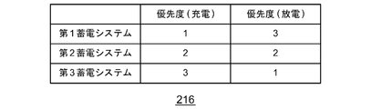
- FIG. 2 shows a table stored in the control unit 216. The priority relating to charging is indicated as priority (charging), and is given to each of the first power storage system 40a to the third power storage system 40c. The priority “1” is the highest, and the priorities “2”, “3”,... Return to FIG.
- Control unit 216 instructs storage system 40 with priority “1” to be charged. After a predetermined period of time has elapsed since the instruction, when the recognition unit 224 recognizes that the backward flow state is recognized, the control unit 216 instructs the storage system 40 of priority “2” to charge. Furthermore, after a predetermined period of time has elapsed since the instruction, when the recognition unit 224 recognizes that the reverse power flow state is recognized, the control unit 216 instructs the storage system 40 with priority “3” to charge. Such processing is continued until the recognition unit 224 does not recognize that it is in the reverse flow state.
- the control unit 216 When the storage system 40 selected by the priority is the first storage system 40a, the control unit 216 causes the bidirectional DC / AC inverter 214 to perform charging.
- the control unit 216 when the storage system 40 selected according to the priority is another storage system 40 other than the first storage system 40a, the control unit 216 generates an instruction signal for causing the selected storage system 40 to perform charging, Output to the second communication unit 220.
- Second communication unit 220 transmits an instruction signal to selected power storage system 40.
- the second communication unit 220 of the selected storage system 40 receives an instruction signal from the first storage system 40a.
- the control unit 216 of the selected storage system 40 causes the bidirectional DC / AC inverter 214 to perform charging.
- At least one of the plurality of power storage systems 40 is selected based on the priority regarding discharge of the plurality of power storage systems 40.
- One storage system 40 is discharged.
- the priority regarding discharge is indicated as priority (discharge), and priority is given to each of the first power storage system 40 a to the third power storage system 40 c.
- the priority “1” is the highest, and the priorities “2”, “3”,...
- the priority for charging is different from the priority for discharging.
- Control unit 216 instructs storage system 40 with priority “1” to discharge. After a predetermined period of time has elapsed since the instruction, when the recognition unit 224 recognizes that the power is in the forward flow state, the control unit 216 instructs the storage system 40 of priority "2" to discharge. Furthermore, after a predetermined period of time has elapsed since the instruction, when the recognition unit 224 recognizes that the forward flow state is recognized, the control unit 216 instructs the storage system 40 of priority “3” to discharge. Such processing is continued until the recognition unit 224 does not recognize that it is in the forward flow state. Since an instruction for discharging the selected storage system 40 may be made in the same manner as in the case of charging, the description is omitted here. As described above, the control unit 216 of the first power storage system 40a controls charging and discharging of the plurality of power storage systems 40 installed in the customer 16 and connected to the power system 30.
- (1-1) Priority generation process related to charging (part 1)
- the user operates the operation unit 222 of the first power storage system 40 a to input priorities that are priorities for the respective power storage systems 40 and that relate to charging.
- the control unit 216 receives the operation of the operation unit 222 to receive the priority for each storage system 40 and the priority for charging.
- the control unit 216 stores priorities related to charging as in the table of FIG.
- the priority for charging may be designated to change for each time zone.
- the control unit 216 charges at least one power storage system 40 of the plurality of power storage systems 40 based on the priority regarding charging.
- the recognition unit 224 of the first power storage system 40 a recognizes the chargeable amount in SB 210.
- a known technique may be used for this process, so the description is omitted here.
- the second communication unit 220 of the first power storage system 40 a communicates with the other power storage system 40 to receive information on the chargeable amount at SB 210 of the other power storage system 40.
- the second communication unit 220 outputs the received information to the recognition unit 224, and the recognition unit 224 recognizes the chargeable amount at SB 210 of the other power storage system 40.
- the recognition unit 224 recognizes the chargeable amount of each of the plurality of power storage systems 40.
- the control unit 216 generates a priority regarding charging for each of the plurality of power storage systems 40 such that the priority becomes higher as the chargeable amount recognized by the recognition unit 224 increases. Such processing is performed regularly, and the priority regarding charge may change each time.
- the recognition unit 224 of the first power storage system 40 a recognizes the amount of discharge at SB 210.
- the amount of discharge is, for example, the amount of discharge the day before.
- the second communication unit 220 of the first power storage system 40 a communicates with the other power storage system 40 to receive information on the discharge amount at SB 210 of the other power storage system 40.
- the second communication unit 220 outputs the received information to the recognition unit 224, and the recognition unit 224 recognizes the discharge amount at SB 210 of the other power storage system 40.
- the recognition unit 224 recognizes the discharge amounts of the plurality of power storage systems 40.
- the control unit 216 generates a priority regarding charging for each of the plurality of power storage systems 40 such that the priority becomes higher as the amount of discharge recognized by the recognition unit 224 increases. Such processing is performed regularly, and the priority regarding charge may change each time.
- (1-4) Generation process of priority for charging (part 4)
- the control unit 216 receives the operation of the operation unit 222, thereby receiving the date when the first power storage system 40a is installed. Such processing is also performed in the other power storage system 40.
- the second communication unit 220 of the first power storage system 40a communicates with the other power storage system 40 to receive information on the date when the other power storage system 40 is installed.
- the second communication unit 220 outputs the received information to the control unit 216, and the control unit 216 acquires the date when the other power storage system 40 was installed.
- the control unit 216 generates priority for charging for each of the plurality of power storage systems 40 based on the date installed in the customer 16. For example, the earlier the installation date of the customer 16, the higher the priority. On the other hand, as the date installed on the customer 16 is later, higher priority may be given. Such priority is updated each time a new storage system 40 is installed in the customer 16.
- (2-1) Generation process of priority for discharge (part 1)
- the user operates the operation unit 222 of the first power storage system 40 a to input priorities that are priorities for the respective power storage systems 40 and regarding discharge.
- control unit 216 receives the priority for each storage system 40 and the priority regarding discharge.
- the control unit 216 stores the priorities regarding the discharge as shown in the table of FIG.
- the priority regarding discharge may be designated to change for each time zone.
- the control unit 216 discharges at least one power storage system 40 among the plurality of power storage systems 40 based on the priority regarding discharge.
- the recognition unit 224 of the first power storage system 40 a recognizes the dischargeable amount at SB 210.
- a known technique may be used for this process, so the description is omitted here.
- the second communication unit 220 of the first power storage system 40 a communicates with the other power storage system 40 to receive information on the dischargeable amount at SB 210 of the other power storage system 40.
- the second communication unit 220 outputs the received information to the recognition unit 224, and the recognition unit 224 recognizes the dischargeable amount at SB 210 of the other power storage system 40.
- the recognition unit 224 recognizes the dischargeable amount of each of the plurality of power storage systems 40.
- the control unit 216 generates a priority regarding discharge for each of the plurality of power storage systems 40 so that the priority becomes higher as the dischargeable amount recognized by the recognition unit 224 increases. Such processing is performed regularly, and the priority regarding discharge may change each time.
- the recognition unit 224 of the first power storage system 40a recognizes the charge amount in SB210.
- the charge amount is, for example, the charge amount of the previous day.
- the second communication unit 220 of the first power storage system 40 a communicates with the other power storage system 40 to receive information on the charge amount at SB 210 of the other power storage system 40.
- the second communication unit 220 outputs the received information to the recognition unit 224, and the recognition unit 224 recognizes the charge amount at SB 210 of the other power storage system 40.
- the recognition unit 224 recognizes the charge amount of each of the plurality of power storage systems 40.
- the control unit 216 generates a priority regarding discharge for each of the plurality of power storage systems 40 such that the priority becomes higher as the charge amount recognized by the recognition unit 224 increases. Such processing is performed regularly, and the priority regarding discharge may change each time.
- Part 4 (2-4) Generation Process of Priority Related to Discharge (Part 4)
- the control unit 216 receives the operation of the operation unit 222, thereby receiving the date when the first power storage system 40a is installed. Such processing is also performed in the other power storage system 40.
- the second communication unit 220 of the first power storage system 40a communicates with the other power storage system 40 to receive information on the date when the other power storage system 40 is installed.
- the second communication unit 220 outputs the received information to the control unit 216, and the control unit 216 acquires the date when the other power storage system 40 was installed.
- the control unit 216 generates a priority regarding discharge for each of the plurality of power storage systems 40 based on the date installed in the customer 16. For example, the earlier the installation date of the customer 16, the higher the priority. On the other hand, as the date installed on the customer 16 is later, higher priority may be given. Such priority is updated each time a new storage system 40 is installed in the customer 16.
- the subject matter of the apparatus, system or method in the present disclosure comprises a computer.
- the computer executes the program to implement the functions of the apparatus, system, or method in the present disclosure.
- the computer includes, as a main hardware configuration, a processor that operates according to a program.
- the processor may be of any type as long as the function can be realized by executing a program.
- the processor is configured of one or more electronic circuits including a semiconductor integrated circuit (IC) or an LSI (Large Scale Integration).
- the plurality of electronic circuits may be integrated on one chip or may be provided on a plurality of chips.
- the plurality of chips may be integrated into one device or may be provided to a plurality of devices.
- the program is recorded in a non-transitory recording medium such as a computer readable ROM, an optical disc, a hard disk drive and the like.
- the program may be stored in advance in a recording medium, or may be supplied to the recording medium via a wide area communication network including the Internet and the like.
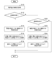
- FIG. 3 is a flowchart showing a control procedure in the first power storage system 40a.
- the first communication unit 218 of the first power storage system 40a acquires information on the amount of power (S10). If a reverse power flow state has occurred based on the information on the amount of electric power (Y in S12), the control unit 216 determines charging within a range in which power purchase does not occur (S14). The control unit 216 selects the storage system 40 to be charged based on the priority related to charging (S16). The control unit 216 instructs the selected storage system 40 to charge (S18).
- control unit 216 can To determine the discharge (S22). The control unit 216 selects the storage system 40 to be discharged based on the priority regarding discharge (S24). Control unit 216 instructs the selected storage system 40 to discharge (S26). If the forward flow state has not occurred based on the information on the amount of power (N at S20), the process is ended.
- At least one of the plurality of power storage systems 40 is charged based on the priority related to charging in the reverse flow state, and based on the priority related to discharge in the forward flow state, a plurality of Since at least one of the storage systems 40 is discharged, the plurality of storage systems 40 can be controlled. Further, since the plurality of power storage systems 40 are collectively controlled, the efficiency of charging or discharging can be improved. Further, since the priority for charging and the priority for discharging are different, priorities suitable for charging and discharging can be set.
- the priority regarding charge is set based on the priority regarding charge input by the user, the priority according to the user's intention can be set.
- the priority related to charging is generated for each of the plurality of storage systems 40 so that the higher the chargeable amount of each of the plurality of storage systems 40 is, the number of storage systems 40 to be charged is increased. Can be reduced.
- the priority related to charging is generated for each of the plurality of storage systems 40 such that the priority increases as the amount of discharge of each of the plurality of storage systems 40 increases, the number of storage systems 40 to be charged is It can be reduced.
- the electrical storage system 40 installed initially is given priority It can be charged.
- the priority related to charging is generated for each of the plurality of storage systems 40 so that the priority is higher as the date installed in the customer 16 is later, the storage system 40 newly installed is given priority It can be charged.
- the priority regarding discharge is set based on the priority regarding discharge input by the user, the priority according to the user's intention can be set.
- the priority regarding discharge is generated for each of the plurality of power storage systems 40 such that the priority becomes higher as the dischargeable amount of each of the plurality of power storage systems 40 increases, the number of power storage systems 40 to be discharged Can be reduced.
- the priority regarding discharge is generated for each of the plurality of power storage systems 40 so that the priority becomes higher as the charge amount of each of the plurality of power storage systems 40 is larger, the number of power storage systems 40 to be discharged is It can be reduced.
- the electrical storage system 40 installed initially is given priority It can be discharged.
- the priority regarding discharge is produced
- the first power storage system 40 a is a first power storage system 40 a installed in the customer 16 and controlling charge and discharge of the plurality of power storage systems 40 connected to the power system 30.
- the recognition unit 224 recognizes whether the reverse power flow state of power from 16 to the power system 30 or the forward power flow state of power from the power system 30 to the customer 16 is performed.
- the control unit 216 is configured to charge at least one power storage system 40 of the plurality of power storage systems 40 based on the priority regarding charging of the plurality of power storage systems 40.
- control unit 216 recognizes that recognition unit 224 is in the forward power state, control unit 216 selects at least one of storage systems 40 of the plurality of storage systems 40 based on the priority regarding discharge of the plurality of storage systems 40. Discharge.
- the priority on charging in the control unit 216 and the priority on discharging are common.
- the priority for charging in the control unit 216 is different from the priority for discharging.
- the control unit 216 charges at least one power storage system 40 of the plurality of power storage systems 40 based on the priority related to charging input from the operation unit 222.
- the recognition unit 224 recognizes the chargeable amount of each of the plurality of power storage systems 40, and the control unit 216 causes the plurality of power storage systems 40 to have higher priority as the chargeable amount recognized by the recognition unit 224 increases. Generate priority for charging for each of the
- the recognition unit 224 recognizes the respective discharge amounts of the plurality of power storage systems 40, and the control unit 216 causes each of the plurality of power storage systems 40 to have a higher priority as the discharge amount recognized by the recognition unit 224 increases. To generate a priority for charging.
- the control unit 216 generates priority for charging for each of the plurality of power storage systems 40 based on the date installed in the customer 16.
- Control unit 216 discharges at least one power storage system 40 of the plurality of power storage systems 40 based on the priority regarding the discharge input from operation unit 222.
- the recognition unit 224 recognizes the dischargeable amount of each of the plurality of power storage systems 40, and the control unit 216 causes the plurality of power storage systems 40 to have a higher priority as the dischargeable amount recognized by the recognition unit 224 increases. Generate priorities for discharge for each of
- the recognition unit 224 recognizes each charge amount of the plurality of power storage systems 40, and the control unit 216 causes each of the plurality of power storage systems 40 to have higher priority as the charge amount recognized by the recognition unit 224 increases. To generate a priority for discharge.
- the control unit 216 generates a priority regarding discharge for each of the plurality of power storage systems 40 based on the date installed in the customer 16.
- This method is a power control method in the first power storage system 40a that controls charging and discharging of a plurality of power storage systems 40 installed in the customer 16 and connected to the power grid 30, and from the customer 16 to the power grid Recognizing whether it is a reverse power flow of power to 30 or a forward power flow of power from the power system 30 to the customer 16, and if it is recognized that it is a reverse power flow, The step of charging at least one power storage system 40 of the plurality of power storage systems 40 based on the priority relating to the charging of the system 40, and the discharge of the plurality of power storage systems 40 when it is recognized that a forward flow state is present. Discharging at least one power storage system 40 of the plurality of power storage systems 40 based on the priority relating to the above.
- Example 2 Similar to the first embodiment, the second embodiment relates to a plurality of power storage systems connected to the power grid at the customer.
- the first power storage system controls the charging and discharging of the plurality of power storage systems while using the priority as the power control device.
- a power management system server is provided separately from the plurality of power storage systems, and the power management system server controls charging / discharging in the plurality of power storage systems while using the priority as a power control device.
- differences from the first embodiment will be mainly described.
- FIG. 4 shows the configuration of the customer 16.
- the customer 16 adds the power management system server 14 to the configuration of FIG.
- the power management system server 14 includes a control unit 216, a first communication unit 218, and a second communication unit 220, and the control unit 216 includes a recognition unit 224.
- the power management system server 14 is a computer for executing the processing of the power management system, and is installed, for example, in the customer 16.
- the power management system server 14 has, for example, a function as a home energy management system (HEMS) controller.
- HEMS home energy management system
- the control unit 216, the first communication unit 218, the second communication unit 220, and the recognition unit 224 in the power management system server 14 execute the same processes as those in the first power storage system 40a of FIG.
- the first power storage system 40 a of FIG. 4 is also set as a slave power storage system 40 as with the other power storage systems 40.
- the degree of freedom of the configuration can be improved.
- Example 3 Similar to the first embodiment, the third embodiment relates to a plurality of power storage systems connected to the power grid at the customer. So far, at least one storage system 40 is selected based on the priority for charging, and the storage system 40 is charged, or based on the priority for discharging, the at least one storage system 40 is selected. The storage system 40 is selectively discharged. On the other hand, in the third embodiment, the plurality of power storage systems 40 are charged or discharged at the same time.
- the configuration of the customer 16 according to the third embodiment is the same type as that of FIG. 1 or FIG. 4. Here, we will focus on the differences from the previous ones.
- the control unit 216 causes the plurality of power storage systems 40 to be charged with each power distributed at a ratio set in advance in the reverse flow power amount.
- an example of the preset ratio is equal. For example, as shown in FIG. 1, when three power storage systems 40 are included, they perform charging equally.
- another example of the predetermined ratio is a value corresponding to the chargeable amount of each of the plurality of power storage systems 40. The chargeable amount of each of the plurality of power storage systems 40 is collected using the second communication unit 220 as before.
- the control unit 216 discharges the plurality of power storage systems 40 with the respective electric power distributed at a ratio set in advance.
- an example of the preset ratio is equal. For example, as shown in FIG. 1, when three power storage systems 40 are included, they uniformly discharge.
- another example of the predetermined ratio is a value corresponding to the dischargeable amount of each of the plurality of power storage systems 40. The dischargeable amount of each of the plurality of storage systems 40 is collected using the second communication unit 220 as before.
- the plurality of power storage systems 40 are charged at the same time, concentration of charge on only one power storage system 40 can be suppressed. Further, since the plurality of power storage systems 40 are equally charged, the charge amounts of the plurality of power storage systems 40 can be equalized. In addition, since the plurality of storage systems 40 are charged based on the chargeable amount of each of the plurality of storage systems 40, charging suitable for each storage system 40 can be performed. Further, since the plurality of power storage systems 40 are discharged simultaneously, concentration of discharge in only one power storage system 40 can be suppressed. Further, since the plurality of power storage systems 40 are evenly discharged, the discharge amounts of the plurality of power storage systems 40 can be equalized. Further, since the plurality of storage systems 40 are charged based on the dischargeable amount of each of the plurality of storage systems 40, discharge suitable for each storage system 40 can be performed.
- the priority regarding charging and the priority regarding discharging are different.
- the present invention is not limited to this.
- the priority for charging and the priority for discharging may be the same. According to this modification, these priorities can be easily set.
- a plurality of power storage systems can be controlled.
Abstract
A recognition unit 224 recognizes whether power is in a reverse flow state from a customer 16 to a power system 30 or in a forward flow state from the power system 30 to the customer 16. If the recognition unit 224 has recognized the reverse flow state, a control unit 216 allows at least one of a first electricity storage system 40a to a third electricity storage system 40c to be charged according to the priority of charging of the first electricity storage system 40a to the third electricity storage system 40c. If the recognition unit 224 has recognized the forward flow state, the control unit 216 allows at least one of the first electricity storage system 40a to the third electricity storage system 40c to be discharged according to the priority of discharging of the first electricity storage system 40a to the third electricity storage system 40c.
Description
本開示は、電力を制御する電力制御装置、電力制御方法、プログラムに関する。
The present disclosure relates to a power control apparatus that controls power, a power control method, and a program.
電力システムでは、太陽光発電システムに蓄電システムを組み合わせられることがある。電力システムにおいて設定されるクリーンモードは、系統連系した商用系統からの買電を抑制し、太陽光発電システムによる発電と蓄電システムの放電によって負荷で消費する電力を賄う(例えば、特許文献1参照)。
In a power system, a photovoltaic system may be combined with a storage system. The clean mode set in the power system suppresses purchase of electricity from a grid-connected commercial system, and covers the power consumed by the load by power generation by the solar power generation system and discharge of the storage system (see, for example, Patent Document 1) ).
蓄電システムの容量が小さい場合、複数の蓄電システムが組み合わせて使用される。複数の蓄電システムを充放電させる場合、これらを独立して制御するよりも、まとめて制御する方が好ましい。
When the capacity of the storage system is small, a plurality of storage systems are used in combination. When charging and discharging a plurality of storage systems, it is more preferable to control them collectively than to control them independently.
本開示はこうした状況に鑑みなされたものであり、その目的は、複数の蓄電システムを制御する技術を提供することにある。
The present disclosure has been made in view of such circumstances, and an object thereof is to provide a technique for controlling a plurality of power storage systems.
上記課題を解決するために、本開示のある態様の電力制御装置は、需要家に設置され、かつ電力系統に接続された複数の蓄電システムの充放電を制御する電力制御装置であって、需要家から電力系統への電力の逆潮流状態であるか、あるいは電力系統から需要家への電力の順潮流状態であるかを認識する認識部と、認識部が逆潮流状態であることを認識した場合、複数の蓄電システムの充電に関する優先度をもとに、複数の蓄電システムのうちの少なくとも1つの蓄電システムを充電させる制御部とを備える。制御部は、認識部が順潮流状態であることを認識した場合、複数の蓄電システムの放電に関する優先度をもとに、複数の蓄電システムのうちの少なくとも1つの蓄電システムを放電させる。
In order to solve the above problems, a power control device according to an aspect of the present disclosure is a power control device that controls charging and discharging of a plurality of power storage systems installed in a customer and connected to a power system. A recognition unit that recognizes whether the power is flowing backward from the house to the power system or a forward flow of power from the power system to the consumer, and the recognition unit recognizes that the power is flowing backward In this case, the control unit is configured to charge at least one power storage system of the plurality of power storage systems based on the priority regarding charging of the plurality of power storage systems. The control unit discharges at least one power storage system of the plurality of power storage systems based on the priority regarding discharge of the plurality of power storage systems when recognizing that the recognition unit is in the forward flow state.
本開示の別の態様は、電力制御方法である。この方法は、需要家に設置され、かつ電力系統に接続された複数の蓄電システムの充放電を制御する電力制御装置での電力制御方法であって、需要家から電力系統への電力の逆潮流状態であるか、あるいは電力系統から需要家への電力の順潮流状態であるかを認識するステップと、逆潮流状態であることを認識した場合、複数の蓄電システムの充電に関する優先度をもとに、複数の蓄電システムのうちの少なくとも1つの蓄電システムを充電させるステップと、順潮流状態であることを認識した場合、複数の蓄電システムの放電に関する優先度をもとに、複数の蓄電システムのうちの少なくとも1つの蓄電システムを放電させるステップと、を備える。
Another aspect of the present disclosure is a power control method. This method is a power control method in a power control apparatus that controls charging and discharging of a plurality of storage systems installed in a consumer and connected to the grid, the reverse flow of power from the consumer to the grid In the step of recognizing whether it is in the state or in the forward power state of power from the power system to the consumer, and when it is recognized that the power is in the reverse power state, priority is given to charging of multiple storage systems. And the step of charging at least one power storage system of the plurality of power storage systems, and if it is recognized that the forward flow state is present, the plurality of power storage systems are Discharging at least one of the storage systems.
なお、以上の構成要素の任意の組合せ、本開示の表現を方法、装置、システム、コンピュータプログラム、またはコンピュータプログラムを記録した記録媒体などの間で変換したものもまた、本開示の態様として有効である。
It is to be noted that any combination of the above-described components, and the expression of the present disclosure converted between a method, an apparatus, a system, a computer program, or a recording medium having a computer program recorded thereon is also effective as an aspect of the present disclosure. is there.
本開示によれば、複数の蓄電システムを制御できる。
According to the present disclosure, a plurality of power storage systems can be controlled.
(実施例1)
本開示の実施例を具体的に説明する前に、本実施例の概要を説明する。実施例は、需要家において電力系統に接続される複数の蓄電システムに関する。需要家は、電力会社等からの電力の供給を受けている施設であり、例えば、住宅、事務所、店舗、工場、公園などである。需要家には太陽電池システムも設置され、太陽電池システムは電力系統および複数の蓄電システムに接続される。太陽電池システムにおいて発電された電力の売電価格が高価であれば、太陽電池システムにおいて発電された電力を電力系統に逆潮流させることによって売電させればよい。一方、太陽電池システムにおいて発電された電力の売電価格が安価であれば、太陽電池システムにおいて発電された電力を売電するよりも、需要家に設置された負荷に供給する方が好ましい。本実施例では後者の場合を想定する。 Example 1
Before specifically describing the embodiments of the present disclosure, an outline of the present embodiment will be described. An embodiment relates to a plurality of power storage systems connected to a power system at a consumer. The customer is a facility receiving power supply from a power company or the like, and is, for example, a house, an office, a store, a factory, a park, or the like. A solar cell system is also installed in the customer, and the solar cell system is connected to the power system and a plurality of storage systems. If the selling price of the power generated in the solar cell system is expensive, the power generated in the solar cell system may be sold by reverse power flow to the power system. On the other hand, if the selling price of the power generated in the solar cell system is low, it is more preferable to supply the load installed to the customer than the selling of the power generated in the solar cell system. The latter case is assumed in this embodiment.
太陽電池システムにおいて発電された電力であって、かつ負荷で消費されない電力は蓄電システムに充電される方が好ましい。このような蓄電システムは、太陽電池システムが発電していないタイミングあるいは太陽電池システムにおいて発電された電力が不足しているタイミングにおいて負荷に電力を供給する。蓄電システムの容量が大きければ、需要家に1つの蓄電システムが設置されればよいが、本実施例では、蓄電システムの容量がそれほど大きくないので、需要家に複数の蓄電システムが設置される。複数の蓄電システムが設置される場合、各蓄電システムが独立して充放電を制御すれば、無駄な制御が実行されるおそれがある。そのため、複数の蓄電システムの充放電をまとめて制御することが望まれる。
The power generated by the solar cell system and not consumed by the load is preferably charged to the storage system. Such a storage system supplies power to the load at a timing when the solar cell system is not generating power or at a timing when the power generated by the solar cell system is insufficient. If the capacity of the storage system is large, one storage system may be installed in the customer. However, in this embodiment, since the capacity of the storage system is not so large, a plurality of storage systems are installed in the customer. When a plurality of power storage systems are installed, unnecessary control may be performed if the respective power storage systems independently control charge and discharge. Therefore, it is desirable to control charging / discharging of a plurality of power storage systems collectively.
本実施例では、複数の蓄電システムのうちの1つがマスタの蓄電システムとなり、残りがスレーブの蓄電システムとなる。マスタの蓄電システムは、複数の蓄電システムのそれぞれに対して、充電に関する優先度と放電に関する優先度とを設定する。マスタの蓄電システムは、複数の蓄電システムにおいて充電すべき状況であるか、あるいは放電すべき状況であるかを判定する。充電すべき状況である場合、マスタの蓄電システムは、充電に関する優先度をもとに、充電させる蓄電システムを選択し、選択した蓄電システムに充電を指示する。指示された蓄電システムは充電を実行する。一方、放電すべき状況である場合、マスタの蓄電システムは、放電に関する優先度をもとに同様の処理を実行する。
In this embodiment, one of the plurality of storage systems is the master storage system, and the remaining is the slave storage system. The storage system of the master sets the priority for charging and the priority for discharging for each of the plurality of storage systems. The storage system of the master determines whether it is a situation to be charged or discharged in a plurality of storage systems. When it is a condition to be charged, the power storage system of the master selects a power storage system to be charged based on the priority regarding charging, and instructs the selected power storage system to charge. The instructed storage system performs charging. On the other hand, when it is the situation which should be discharged, the storage system of a master performs the same processing based on the priority regarding discharge.
図1は、需要家16の構成を示す。需要家16には、電力系統30、スマートメータ32、分電盤34、負荷36、太陽電池システム38、蓄電システム40と総称される第1蓄電システム40a、第2蓄電システム40b、第3蓄電システム40c、コンセント44と総称される第1コンセント44a、第2コンセント44b、第3コンセント44cが設置される。太陽電池システム38は、PV(Photovoltaics)200、PV用DC(Direct Current)/DC202、PV用DC/AC(Alternating Current)204を含む。第1蓄電システム40aは、SB(Storage Battery)210、SB用DC/DC212、双方向DC/ACインバータ214、制御部216、第1通信部218、第2通信部220、操作部222を含み、制御部216は認識部224を含む。第2蓄電システム40b、第3蓄電システム40cは第1蓄電システム40aと同様に構成される。
FIG. 1 shows the configuration of the customer 16. The customer 16 includes a power storage system 30, a smart meter 32, a distribution board 34, a load 36, a solar cell system 38, and a first storage system 40a collectively referred to as a storage system 40, a second storage system 40b, and a third storage system. 40c, a first outlet 44a, a second outlet 44b, and a third outlet 44c, collectively referred to as an outlet 44, are installed. The solar cell system 38 includes PV (Photovoltaics) 200, PV DC (Direct Current) / DC 202, and PV DC / AC (Alternating Current) 204. The first power storage system 40a includes a storage battery (SB) 210, a DC / DC 212 for SB, a bidirectional DC / AC inverter 214, a control unit 216, a first communication unit 218, a second communication unit 220, and an operation unit 222. The control unit 216 includes a recognition unit 224. The second power storage system 40b and the third power storage system 40c are configured in the same manner as the first power storage system 40a.
第1蓄電システム40aと分電盤34は第1コンセント44aによって接続され、第2蓄電システム40bと分電盤34は第2コンセント44bによって接続され、第3蓄電システム40cと分電盤34は第3コンセント44cによって接続される。つまり、蓄電システム40はコンセント44において分電盤34から着脱可能に構成される。そのため、需要家16において蓄電システム40を増設する場合、新たな蓄電システム40をコンセント44に接続すればよい。蓄電システム40およびコンセント44の数は「3」に限定されない。需要家16には、ヒートポンプ給湯機等が設置されてもよいが、ここではこれらを省略する。
The first storage system 40a and the distribution board 34 are connected by the first outlet 44a, the second storage system 40b and the distribution board 34 are connected by the second outlet 44b, and the third storage system 40c and the distribution board 34 are It is connected by 3 outlets 44c. That is, the storage system 40 is configured to be detachable from the distribution board 34 at the outlet 44. Therefore, in the case where the power storage system 40 is added in the customer 16, a new power storage system 40 may be connected to the outlet 44. The number of storage systems 40 and outlets 44 is not limited to “3”. A heat pump water heater or the like may be installed at the customer 16, but these are omitted here.
需要家16は、例えば、一戸建ての住宅、マンションなどの集合住宅、コンビニエンスストアまたはスーパーマーケットなどの店舗、ビルなどの商用施設、工場であり、前述のごとく、電力会社等からの電力の供給を受けている施設である。電力系統30は電力事業者等によって提供される。スマートメータ32は、電力系統30に接続されたデジタル式の電力量計である。スマートメータ32は、電力系統30から入ってくる順潮流の電力量と、電力系統30へ出て行く逆潮流の電力量とを計測可能である。スマートメータ32は、通信機能を有し、第1蓄電システム40aと通信可能である。スマートメータ32は、計測した結果、つまり順潮流の電力量あるいは逆潮流の電力量を第1蓄電システム40aに送信する。
The customer 16 is, for example, a single-family house, an apartment house such as an apartment, a store such as a convenience store or a supermarket, a commercial facility such as a building, a factory. It is an existing facility. The power system 30 is provided by a power company or the like. The smart meter 32 is a digital watt-hour meter connected to the power system 30. The smart meter 32 can measure the amount of forward flow incoming from the power system 30 and the amount of reverse flow outgoing to the power system 30. The smart meter 32 has a communication function and can communicate with the first power storage system 40a. The smart meter 32 transmits the measurement result, that is, the amount of power of forward flow or the amount of power of reverse flow to the first power storage system 40a.
配電線42は、スマートメータ32と分電盤34とを結ぶ。分電盤34は、スマートメータ32に接続され、スマートメータ32を介して電力系統30に接続される。また、分電盤34は、負荷36を接続し、負荷36に電力を供給する。負荷36は分電盤34から供給される電力を消費する機器である。負荷36は、空調機器(エアコン)、テレビジョン受信装置(テレビ)、照明装置、冷蔵庫等の機器を含む。ここでは、分電盤34に1つの負荷36が接続されているが、分電盤34に複数の負荷36が接続されてもよい。
The distribution line 42 connects the smart meter 32 and the distribution board 34. The distribution board 34 is connected to the smart meter 32, and is connected to the power system 30 via the smart meter 32. The distribution board 34 also connects the load 36 and supplies power to the load 36. The load 36 is a device that consumes the power supplied from the distribution board 34. The load 36 includes equipment such as an air conditioner (air conditioner), a television receiver (television), a lighting device, and a refrigerator. Here, although one load 36 is connected to the distribution board 34, a plurality of loads 36 may be connected to the distribution board 34.
PV200は、太陽電池であり、再生可能エネルギー発電装置である。PV200は、光起電力効果を利用し、光エネルギーを直接電力に変換する。太陽電池として、シリコン太陽電池、化合物半導体などを素材にした太陽電池、色素増感型(有機太陽電池)等が使用される。PV200は、PV用DC/DC202に接続され、発電した直流電力をPV用DC/DC202に出力する。
The PV 200 is a solar cell and is a renewable energy generator. The PV 200 directly converts light energy into electrical power using the photovoltaic effect. As a solar cell, a solar cell made of a silicon solar cell, a compound semiconductor or the like, a dye-sensitized type (organic solar cell) or the like is used. The PV 200 is connected to the PV DC / DC 202, and outputs the generated DC power to the PV DC / DC 202.
PV用DC/DC202は、DC-DCコンバータであり、PV200から出力される直流電力を、所望の電圧値の直流電力に変換し、変換した直流電力をPV用DC/AC204に出力する。PV用DC/DC202は、例えば、昇圧チョッパで構成される。PV用DC/DC202は、PV200の出力電力が最大になるようMPPT(Maximum Power Point Tracking)制御される。PV用DC/AC204は、DC-ACインバータであり、PV用DC/DC202から出力される直流電力を交流電力に変換し、交流電力を配電線42に出力する。ここで、PV200、PV用DC/DC202、PV用DC/AC204は一体的に形成されてもよく、その場合であっても、これを太陽電池システム38と呼ぶ。
The PV DC / DC 202 is a DC-DC converter, converts DC power output from the PV 200 into DC power of a desired voltage value, and outputs the converted DC power to the PV DC / AC 204. The PV DC / DC 202 is configured by, for example, a boost chopper. The PV DC / DC 202 is MPPT (Maximum Power Point Tracking) controlled to maximize the output power of the PV 200. The PV DC / AC 204 is a DC-AC inverter, converts DC power output from the PV DC / DC 202 into AC power, and outputs AC power to the distribution line 42. Here, the PV 200, the PV DC / DC 202, and the PV DC / AC 204 may be integrally formed, and even in that case, this is referred to as a solar cell system 38.
第1蓄電システム40aにおけるSB210は、電力を充放電可能な蓄電池であり、リチウムイオン蓄電池、ニッケル水素蓄電池、鉛蓄電池、電気二重層キャパシタ、リチウムイオンキャパシタ等を含む。SB210はSB用DC/DC212に接続される。SB用DC/DC212は、DC-DCコンバータであり、SB210側の直流電力と、双方向DC/ACインバータ214側の直流電力との間の変換を実行する。
The SB 210 in the first storage system 40a is a storage battery capable of charging and discharging electric power, and includes a lithium ion storage battery, a nickel hydrogen storage battery, a lead storage battery, an electric double layer capacitor, a lithium ion capacitor, and the like. The SB 210 is connected to the DC / DC 212 for SB. The SB DC / DC 212 is a DC-DC converter, and performs conversion between the DC power on the SB 210 side and the DC power on the bidirectional DC / AC inverter 214 side.
双方向DC/ACインバータ214は、SB用DC/DC212と分電盤34との間に接続される。双方向DC/ACインバータ214は、分電盤34からの交流電力を直流電力に変換し、変換した直流電力をSB用DC/DC212に出力する。また、双方向DC/ACインバータ214は、SB用DC/DC212からの直流電力を交流電力に変換し、変換した交流電力を分電盤34に出力する。つまり、双方向DC/ACインバータ214によってSB210は充放電される。このような双方向DC/ACインバータ214の制御は制御部216によってなされる。
The bi-directional DC / AC inverter 214 is connected between the DC / DC 212 for SB and the distribution board 34. The bidirectional DC / AC inverter 214 converts AC power from the distribution board 34 into DC power, and outputs the converted DC power to the SB DC / DC 212. The bidirectional DC / AC inverter 214 converts the DC power from the SB DC / DC 212 into AC power, and outputs the converted AC power to the distribution board 34. That is, the SB 210 is charged and discharged by the bi-directional DC / AC inverter 214. Such control of the bidirectional DC / AC inverter 214 is performed by the control unit 216.
制御部216には第1通信部218と第2通信部220とが接続される。第1通信部218はスマートメータ32と通信し、第2通信部220は他の蓄電システム40との間で通信を実行する。第1通信部218および第2通信部220における通信には、有線通信あるいは無線通信が使用される。第1通信部218および第2通信部220における通信が共通の方式によりなされている場合、第1通信部218と第2通信部220は一体化されてもよい。ここで、SB210、SB用DC/DC212、双方向DC/ACインバータ214、制御部216、第1通信部218、第2通信部220は1つの筐体に格納されてもよく、その場合であっても、これを蓄電システム40と呼ぶ。前述のごとく、第2蓄電システム40b、第3蓄電システム40cは第1蓄電システム40aと同様に構成される。
The first communication unit 218 and the second communication unit 220 are connected to the control unit 216. The first communication unit 218 communicates with the smart meter 32, and the second communication unit 220 communicates with another power storage system 40. Wired communication or wireless communication is used for communication in the first communication unit 218 and the second communication unit 220. When the communication in the first communication unit 218 and the second communication unit 220 is performed in a common manner, the first communication unit 218 and the second communication unit 220 may be integrated. Here, the SB 210, the SB DC / DC 212, the bidirectional DC / AC inverter 214, the control unit 216, the first communication unit 218, and the second communication unit 220 may be stored in one case, in that case. Even this is called a storage system 40. As described above, the second power storage system 40b and the third power storage system 40c are configured in the same manner as the first power storage system 40a.
第1蓄電システム40aの操作部222は、ユーザが操作可能なインターフェイスであり、例えば、ボタンにより構成される。ユーザは、操作部222を操作することによって、制御部216に対して第1蓄電システム40aをマスタに設定する。このようなマスタの第1蓄電システム40aは、複数の蓄電システム40の充放電を制御するので、電力制御装置であるといえる。第2蓄電システム40bと第3蓄電システム40cにも操作部222が備えられており、ユーザは操作部222を操作することによって、第2蓄電システム40bと第3蓄電システム40cとをいずれもスレーブに設定する。
The operation unit 222 of the first power storage system 40a is an interface that can be operated by the user, and is configured of, for example, a button. The user operates the operation unit 222 to set the first power storage system 40 a as a master to the control unit 216. Such a master first power storage system 40a controls charging / discharging of the plurality of power storage systems 40, and thus can be said to be a power control device. The second power storage system 40b and the third power storage system 40c are also provided with the operation unit 222, and the user operates the operation unit 222 to make both the second power storage system 40b and the third power storage system 40c as slaves. Set
第1蓄電システム40aの第1通信部218は、順潮流の電力量あるいは逆潮流の電力量をスマートメータ32から受信する。第1通信部218は、順潮流の電力量あるいは逆潮流の電力量を認識部224に出力する。認識部224は、逆潮流の電力量がしきい値(以下、「第1しきい値」という)よりも大きい場合に、需要家16から電力系統30への電力の逆潮流状態であることを認識する。認識部224は、逆潮流の電力量が第1しきい値以下である場合に、逆潮流状態でないことを認識する。一方、認識部224は、順潮流の電力量がしきい値(以下、「第2しきい値」という)よりも大きい場合に、電力系統30から需要家16への電力の順潮流状態であることを認識する。認識部224は、順潮流の電力量が第2しきい値以下である場合に、順潮流状態でないことを認識する。
The first communication unit 218 of the first power storage system 40 a receives the power amount of forward flow or the power amount of reverse flow from the smart meter 32. The first communication unit 218 outputs the power amount of forward flow or the power amount of reverse flow to the recognition unit 224. The recognition unit 224 determines that the power flow from the customer 16 to the power system 30 is in the reverse flow state when the reverse flow power amount is larger than the threshold (hereinafter, referred to as “first threshold”). recognize. The recognition unit 224 recognizes that it is not in the reverse flow state when the amount of power of the reverse flow is equal to or less than the first threshold. On the other hand, when the amount of power of forward flow is larger than the threshold (hereinafter referred to as “second threshold”), recognition unit 224 is in a forward flow state of power from power system 30 to customer 16. Recognize that. The recognition unit 224 recognizes that it is not in the forward flow state when the amount of power in the forward flow is equal to or less than the second threshold.
制御部216は、認識部224が逆潮流状態であることを認識した場合、複数の蓄電システム40の充電に関する優先度をもとに、複数の蓄電システム40のうちの少なくとも1つの蓄電システム40を充電させる。図2は、制御部216に記憶されたテーブルを示す。充電に関する優先度は優先度(充電)と示され、第1蓄電システム40aから第3蓄電システム40cのそれぞれに対して優先度が付与される。優先度「1」が最も優先度が高く、優先度「2」、「3」・・・の順で優先度が低くなる。図1に戻る。
When control unit 216 recognizes that recognition unit 224 is in the reverse power flow state, at least one power storage system 40 of the plurality of power storage systems 40 is selected based on the priority regarding charging of the plurality of power storage systems 40. Charge it. FIG. 2 shows a table stored in the control unit 216. The priority relating to charging is indicated as priority (charging), and is given to each of the first power storage system 40a to the third power storage system 40c. The priority “1” is the highest, and the priorities “2”, “3”,... Return to FIG.
制御部216は、優先度「1」の蓄電システム40に充電を指示する。指示してから一定期間経過した後、認識部224が逆潮流状態であることを認識している場合、制御部216は、優先度「2」の蓄電システム40に充電を指示する。さらに、指示してから一定期間経過した後、認識部224が逆潮流状態であることを認識している場合、制御部216は、優先度「3」の蓄電システム40に充電を指示する。このような処理は、認識部224が逆潮流状態であることを認識しなくなるまで、続けられる。
Control unit 216 instructs storage system 40 with priority “1” to be charged. After a predetermined period of time has elapsed since the instruction, when the recognition unit 224 recognizes that the backward flow state is recognized, the control unit 216 instructs the storage system 40 of priority “2” to charge. Furthermore, after a predetermined period of time has elapsed since the instruction, when the recognition unit 224 recognizes that the reverse power flow state is recognized, the control unit 216 instructs the storage system 40 with priority “3” to charge. Such processing is continued until the recognition unit 224 does not recognize that it is in the reverse flow state.
優先度によって選択した蓄電システム40が第1蓄電システム40aである場合、制御部216は、双方向DC/ACインバータ214に充電を実行させる。一方、優先度によって選択した蓄電システム40が第1蓄電システム40a以外の他の蓄電システム40である場合、制御部216は、選択した蓄電システム40に充電を実行させるための指示信号を生成し、第2通信部220に出力する。第2通信部220は、選択された蓄電システム40に対して指示信号を送信する。選択された蓄電システム40の第2通信部220は、第1蓄電システム40aからの指示信号を受信する。選択された蓄電システム40の制御部216は、双方向DC/ACインバータ214に充電を実行させる。
When the storage system 40 selected by the priority is the first storage system 40a, the control unit 216 causes the bidirectional DC / AC inverter 214 to perform charging. On the other hand, when the storage system 40 selected according to the priority is another storage system 40 other than the first storage system 40a, the control unit 216 generates an instruction signal for causing the selected storage system 40 to perform charging, Output to the second communication unit 220. Second communication unit 220 transmits an instruction signal to selected power storage system 40. The second communication unit 220 of the selected storage system 40 receives an instruction signal from the first storage system 40a. The control unit 216 of the selected storage system 40 causes the bidirectional DC / AC inverter 214 to perform charging.
第1蓄電システム40aの制御部216は、認識部224が順潮流状態であることを認識した場合、複数の蓄電システム40の放電に関する優先度をもとに、複数の蓄電システム40のうちの少なくとも1つの蓄電システム40を放電させる。図2において放電に関する優先度は優先度(放電)と示され、第1蓄電システム40aから第3蓄電システム40cのそれぞれに対して優先度が付与される。ここでも優先度「1」が最も優先度が高く、優先度「2」、「3」・・・の順で優先度が低くなる。充電に関する優先度と、放電に関する優先度とは異なる。図1に戻る。
When the control unit 216 of the first power storage system 40 a recognizes that the recognition unit 224 is in the forward power state, at least one of the plurality of power storage systems 40 is selected based on the priority regarding discharge of the plurality of power storage systems 40. One storage system 40 is discharged. In FIG. 2, the priority regarding discharge is indicated as priority (discharge), and priority is given to each of the first power storage system 40 a to the third power storage system 40 c. Here too, the priority “1” is the highest, and the priorities “2”, “3”,... The priority for charging is different from the priority for discharging. Return to FIG.
制御部216は、優先度「1」の蓄電システム40に放電を指示する。指示してから一定期間経過した後、認識部224が順潮流状態であることを認識している場合、制御部216は、優先度「2」の蓄電システム40に放電を指示する。さらに、指示してから一定期間経過した後、認識部224が順潮流状態であることを認識している場合、制御部216は、優先度「3」の蓄電システム40に放電を指示する。このような処理は、認識部224が順潮流状態であることを認識しなくなるまで、続けられる。選択した蓄電システム40に対する放電の指示は、充電の場合と同様になされればよいので、ここでは説明を省略する。このように第1蓄電システム40aの制御部216は、需要家16に設置され、かつ電力系統30に接続された複数の蓄電システム40の充放電を制御する
Control unit 216 instructs storage system 40 with priority “1” to discharge. After a predetermined period of time has elapsed since the instruction, when the recognition unit 224 recognizes that the power is in the forward flow state, the control unit 216 instructs the storage system 40 of priority "2" to discharge. Furthermore, after a predetermined period of time has elapsed since the instruction, when the recognition unit 224 recognizes that the forward flow state is recognized, the control unit 216 instructs the storage system 40 of priority “3” to discharge. Such processing is continued until the recognition unit 224 does not recognize that it is in the forward flow state. Since an instruction for discharging the selected storage system 40 may be made in the same manner as in the case of charging, the description is omitted here. As described above, the control unit 216 of the first power storage system 40a controls charging and discharging of the plurality of power storage systems 40 installed in the customer 16 and connected to the power system 30.
以下では、(1-1)から(1-4)の順に充電に関する優先度の生成処理を説明してから、(2-1)から(2-4)の順に放電に関する優先度の生成処理を説明する。
(1-1)充電に関する優先度の生成処理(その1)
ユーザは第1蓄電システム40aの操作部222を操作することによって、各蓄電システム40に対する優先度であって、かつ充電に関する優先度を入力する。制御部216は、操作部222の操作を受けつけることによって、各蓄電システム40に対する優先度であって、かつ充電に関する優先度を受けつける。制御部216は、図2のテーブルのように、充電に関する優先度を記憶する。充電に関する優先度は、時間帯毎に変わるように指定されてもよい。制御部216は、充電に関する優先度をもとに、複数の蓄電システム40のうちの少なくとも1つの蓄電システム40を充電させる。 In the following, the process of generating priorities for charging in the order of (1-1) to (1-4) will be described, and then the process of generating priorities for discharging in the order of (2-1) to (2-4) will be described. explain.
(1-1) Priority generation process related to charging (part 1)
The user operates theoperation unit 222 of the first power storage system 40 a to input priorities that are priorities for the respective power storage systems 40 and that relate to charging. The control unit 216 receives the operation of the operation unit 222 to receive the priority for each storage system 40 and the priority for charging. The control unit 216 stores priorities related to charging as in the table of FIG. The priority for charging may be designated to change for each time zone. The control unit 216 charges at least one power storage system 40 of the plurality of power storage systems 40 based on the priority regarding charging.
(1-1)充電に関する優先度の生成処理(その1)
ユーザは第1蓄電システム40aの操作部222を操作することによって、各蓄電システム40に対する優先度であって、かつ充電に関する優先度を入力する。制御部216は、操作部222の操作を受けつけることによって、各蓄電システム40に対する優先度であって、かつ充電に関する優先度を受けつける。制御部216は、図2のテーブルのように、充電に関する優先度を記憶する。充電に関する優先度は、時間帯毎に変わるように指定されてもよい。制御部216は、充電に関する優先度をもとに、複数の蓄電システム40のうちの少なくとも1つの蓄電システム40を充電させる。 In the following, the process of generating priorities for charging in the order of (1-1) to (1-4) will be described, and then the process of generating priorities for discharging in the order of (2-1) to (2-4) will be described. explain.
(1-1) Priority generation process related to charging (part 1)
The user operates the
(1-2)充電に関する優先度の生成処理(その2)
第1蓄電システム40aの認識部224はSB210における充電可能量を認識する。この処理には公知の技術が使用されればよいので、ここでは説明を省略する。また、第1蓄電システム40aの第2通信部220は、他の蓄電システム40と通信することによって、他の蓄電システム40のSB210における充電可能量に関する情報を受信する。第2通信部220は、受信した情報を認識部224に出力し、認識部224は、他の蓄電システム40のSB210における充電可能量を認識する。その結果、認識部224は、複数の蓄電システム40のそれぞれの充電可能量を認識する。制御部216は、認識部224において認識した充電可能量が多いほど優先度が高くなるように、複数の蓄電システム40のそれぞれに対して充電に関する優先度を生成する。このような処理は定期的になされており、その都度、充電に関する優先度が変わることもある。 (1-2) Generation process of priority for charging (part 2)
Therecognition unit 224 of the first power storage system 40 a recognizes the chargeable amount in SB 210. A known technique may be used for this process, so the description is omitted here. The second communication unit 220 of the first power storage system 40 a communicates with the other power storage system 40 to receive information on the chargeable amount at SB 210 of the other power storage system 40. The second communication unit 220 outputs the received information to the recognition unit 224, and the recognition unit 224 recognizes the chargeable amount at SB 210 of the other power storage system 40. As a result, the recognition unit 224 recognizes the chargeable amount of each of the plurality of power storage systems 40. The control unit 216 generates a priority regarding charging for each of the plurality of power storage systems 40 such that the priority becomes higher as the chargeable amount recognized by the recognition unit 224 increases. Such processing is performed regularly, and the priority regarding charge may change each time.
第1蓄電システム40aの認識部224はSB210における充電可能量を認識する。この処理には公知の技術が使用されればよいので、ここでは説明を省略する。また、第1蓄電システム40aの第2通信部220は、他の蓄電システム40と通信することによって、他の蓄電システム40のSB210における充電可能量に関する情報を受信する。第2通信部220は、受信した情報を認識部224に出力し、認識部224は、他の蓄電システム40のSB210における充電可能量を認識する。その結果、認識部224は、複数の蓄電システム40のそれぞれの充電可能量を認識する。制御部216は、認識部224において認識した充電可能量が多いほど優先度が高くなるように、複数の蓄電システム40のそれぞれに対して充電に関する優先度を生成する。このような処理は定期的になされており、その都度、充電に関する優先度が変わることもある。 (1-2) Generation process of priority for charging (part 2)
The
(1-3)充電に関する優先度の生成処理(その3)
第1蓄電システム40aの認識部224はSB210における放電量を認識する。放電量は、例えば前日の放電量である。また、第1蓄電システム40aの第2通信部220は、他の蓄電システム40と通信することによって、他の蓄電システム40のSB210における放電量に関する情報を受信する。第2通信部220は、受信した情報を認識部224に出力し、認識部224は、他の蓄電システム40のSB210における放電量を認識する。その結果、認識部224は、複数の蓄電システム40のそれぞれの放電量を認識する。制御部216は、認識部224において認識した放電量が多いほど優先度が高くなるように、複数の蓄電システム40のそれぞれに対して充電に関する優先度を生成する。このような処理は定期的になされており、その都度、充電に関する優先度が変わることもある。 (1-3) Generation process of priority for charging (part 3)
Therecognition unit 224 of the first power storage system 40 a recognizes the amount of discharge at SB 210. The amount of discharge is, for example, the amount of discharge the day before. In addition, the second communication unit 220 of the first power storage system 40 a communicates with the other power storage system 40 to receive information on the discharge amount at SB 210 of the other power storage system 40. The second communication unit 220 outputs the received information to the recognition unit 224, and the recognition unit 224 recognizes the discharge amount at SB 210 of the other power storage system 40. As a result, the recognition unit 224 recognizes the discharge amounts of the plurality of power storage systems 40. The control unit 216 generates a priority regarding charging for each of the plurality of power storage systems 40 such that the priority becomes higher as the amount of discharge recognized by the recognition unit 224 increases. Such processing is performed regularly, and the priority regarding charge may change each time.
第1蓄電システム40aの認識部224はSB210における放電量を認識する。放電量は、例えば前日の放電量である。また、第1蓄電システム40aの第2通信部220は、他の蓄電システム40と通信することによって、他の蓄電システム40のSB210における放電量に関する情報を受信する。第2通信部220は、受信した情報を認識部224に出力し、認識部224は、他の蓄電システム40のSB210における放電量を認識する。その結果、認識部224は、複数の蓄電システム40のそれぞれの放電量を認識する。制御部216は、認識部224において認識した放電量が多いほど優先度が高くなるように、複数の蓄電システム40のそれぞれに対して充電に関する優先度を生成する。このような処理は定期的になされており、その都度、充電に関する優先度が変わることもある。 (1-3) Generation process of priority for charging (part 3)
The
(1-4)充電に関する優先度の生成処理(その4)
第1蓄電システム40aを需要家16に設置した際に、ユーザは操作部222を操作して、設置した日付を入力する。制御部216は、操作部222の操作を受けつけることによって、第1蓄電システム40aを設置した日付を受けつける。また、このような処理は他の蓄電システム40においてもなされる。また、第1蓄電システム40aの第2通信部220は、他の蓄電システム40と通信することによって、他の蓄電システム40が設置された日付に関する情報を受信する。第2通信部220は、受信した情報を制御部216に出力し、制御部216は、他の蓄電システム40が設置された日付を取得する。制御部216は、需要家16に設置した日付をもとに、複数の蓄電システム40のそれぞれに対して充電に関する優先度を生成する。例えば、需要家16に設置した日付が早いほど、高い優先度が付与される。一方、需要家16に設置した日付が遅いほど、高い優先度が付与されてもよい。このような優先度は、新しい蓄電システム40が需要家16に設置される毎に更新される。 (1-4) Generation process of priority for charging (part 4)
When the firstpower storage system 40a is installed in the customer 16, the user operates the operation unit 222 to input the installed date. The control unit 216 receives the operation of the operation unit 222, thereby receiving the date when the first power storage system 40a is installed. Such processing is also performed in the other power storage system 40. The second communication unit 220 of the first power storage system 40a communicates with the other power storage system 40 to receive information on the date when the other power storage system 40 is installed. The second communication unit 220 outputs the received information to the control unit 216, and the control unit 216 acquires the date when the other power storage system 40 was installed. The control unit 216 generates priority for charging for each of the plurality of power storage systems 40 based on the date installed in the customer 16. For example, the earlier the installation date of the customer 16, the higher the priority. On the other hand, as the date installed on the customer 16 is later, higher priority may be given. Such priority is updated each time a new storage system 40 is installed in the customer 16.
第1蓄電システム40aを需要家16に設置した際に、ユーザは操作部222を操作して、設置した日付を入力する。制御部216は、操作部222の操作を受けつけることによって、第1蓄電システム40aを設置した日付を受けつける。また、このような処理は他の蓄電システム40においてもなされる。また、第1蓄電システム40aの第2通信部220は、他の蓄電システム40と通信することによって、他の蓄電システム40が設置された日付に関する情報を受信する。第2通信部220は、受信した情報を制御部216に出力し、制御部216は、他の蓄電システム40が設置された日付を取得する。制御部216は、需要家16に設置した日付をもとに、複数の蓄電システム40のそれぞれに対して充電に関する優先度を生成する。例えば、需要家16に設置した日付が早いほど、高い優先度が付与される。一方、需要家16に設置した日付が遅いほど、高い優先度が付与されてもよい。このような優先度は、新しい蓄電システム40が需要家16に設置される毎に更新される。 (1-4) Generation process of priority for charging (part 4)
When the first
(2-1)放電に関する優先度の生成処理(その1)
ユーザは第1蓄電システム40aの操作部222を操作することによって、各蓄電システム40に対する優先度であって、かつ放電に関する優先度を入力する。制御部216は、操作部222の操作を受けつけることによって、各蓄電システム40に対する優先度であって、かつ放電に関する優先度を受けつける。制御部216は、図2のテーブルのように、放電に関する優先度を記憶する。放電に関する優先度は、時間帯毎に変わるように指定されてもよい。制御部216は、放電に関する優先度をもとに、複数の蓄電システム40のうちの少なくとも1つの蓄電システム40を放電させる。 (2-1) Generation process of priority for discharge (part 1)
The user operates theoperation unit 222 of the first power storage system 40 a to input priorities that are priorities for the respective power storage systems 40 and regarding discharge. By receiving the operation of operation unit 222, control unit 216 receives the priority for each storage system 40 and the priority regarding discharge. The control unit 216 stores the priorities regarding the discharge as shown in the table of FIG. The priority regarding discharge may be designated to change for each time zone. The control unit 216 discharges at least one power storage system 40 among the plurality of power storage systems 40 based on the priority regarding discharge.
ユーザは第1蓄電システム40aの操作部222を操作することによって、各蓄電システム40に対する優先度であって、かつ放電に関する優先度を入力する。制御部216は、操作部222の操作を受けつけることによって、各蓄電システム40に対する優先度であって、かつ放電に関する優先度を受けつける。制御部216は、図2のテーブルのように、放電に関する優先度を記憶する。放電に関する優先度は、時間帯毎に変わるように指定されてもよい。制御部216は、放電に関する優先度をもとに、複数の蓄電システム40のうちの少なくとも1つの蓄電システム40を放電させる。 (2-1) Generation process of priority for discharge (part 1)
The user operates the
(2-2)放電に関する優先度の生成処理(その2)
第1蓄電システム40aの認識部224はSB210における放電可能量を認識する。この処理には公知の技術が使用されればよいので、ここでは説明を省略する。また、第1蓄電システム40aの第2通信部220は、他の蓄電システム40と通信することによって、他の蓄電システム40のSB210における放電可能量に関する情報を受信する。第2通信部220は、受信した情報を認識部224に出力し、認識部224は、他の蓄電システム40のSB210における放電可能量を認識する。その結果、認識部224は、複数の蓄電システム40のそれぞれの放電可能量を認識する。制御部216は、認識部224において認識した放電可能量が多いほど優先度が高くなるように、複数の蓄電システム40のそれぞれに対して放電に関する優先度を生成する。このような処理は定期的になされており、その都度、放電に関する優先度が変わることもある。 (2-2) Generation process of priority regarding discharge (part 2)
Therecognition unit 224 of the first power storage system 40 a recognizes the dischargeable amount at SB 210. A known technique may be used for this process, so the description is omitted here. The second communication unit 220 of the first power storage system 40 a communicates with the other power storage system 40 to receive information on the dischargeable amount at SB 210 of the other power storage system 40. The second communication unit 220 outputs the received information to the recognition unit 224, and the recognition unit 224 recognizes the dischargeable amount at SB 210 of the other power storage system 40. As a result, the recognition unit 224 recognizes the dischargeable amount of each of the plurality of power storage systems 40. The control unit 216 generates a priority regarding discharge for each of the plurality of power storage systems 40 so that the priority becomes higher as the dischargeable amount recognized by the recognition unit 224 increases. Such processing is performed regularly, and the priority regarding discharge may change each time.
第1蓄電システム40aの認識部224はSB210における放電可能量を認識する。この処理には公知の技術が使用されればよいので、ここでは説明を省略する。また、第1蓄電システム40aの第2通信部220は、他の蓄電システム40と通信することによって、他の蓄電システム40のSB210における放電可能量に関する情報を受信する。第2通信部220は、受信した情報を認識部224に出力し、認識部224は、他の蓄電システム40のSB210における放電可能量を認識する。その結果、認識部224は、複数の蓄電システム40のそれぞれの放電可能量を認識する。制御部216は、認識部224において認識した放電可能量が多いほど優先度が高くなるように、複数の蓄電システム40のそれぞれに対して放電に関する優先度を生成する。このような処理は定期的になされており、その都度、放電に関する優先度が変わることもある。 (2-2) Generation process of priority regarding discharge (part 2)
The
(2-3)放電に関する優先度の生成処理(その3)
第1蓄電システム40aの認識部224はSB210における充電量を認識する。充電量は、例えば前日の充電量である。また、第1蓄電システム40aの第2通信部220は、他の蓄電システム40と通信することによって、他の蓄電システム40のSB210における充電量に関する情報を受信する。第2通信部220は、受信した情報を認識部224に出力し、認識部224は、他の蓄電システム40のSB210における充電量を認識する。その結果、認識部224は、複数の蓄電システム40のそれぞれの充電量を認識する。制御部216は、認識部224において認識した充電量が多いほど優先度が高くなるように、複数の蓄電システム40のそれぞれに対して放電に関する優先度を生成する。このような処理は定期的になされており、その都度、放電に関する優先度が変わることもある。 (2-3) Generation process of priority for discharge (part 3)
Therecognition unit 224 of the first power storage system 40a recognizes the charge amount in SB210. The charge amount is, for example, the charge amount of the previous day. The second communication unit 220 of the first power storage system 40 a communicates with the other power storage system 40 to receive information on the charge amount at SB 210 of the other power storage system 40. The second communication unit 220 outputs the received information to the recognition unit 224, and the recognition unit 224 recognizes the charge amount at SB 210 of the other power storage system 40. As a result, the recognition unit 224 recognizes the charge amount of each of the plurality of power storage systems 40. The control unit 216 generates a priority regarding discharge for each of the plurality of power storage systems 40 such that the priority becomes higher as the charge amount recognized by the recognition unit 224 increases. Such processing is performed regularly, and the priority regarding discharge may change each time.
第1蓄電システム40aの認識部224はSB210における充電量を認識する。充電量は、例えば前日の充電量である。また、第1蓄電システム40aの第2通信部220は、他の蓄電システム40と通信することによって、他の蓄電システム40のSB210における充電量に関する情報を受信する。第2通信部220は、受信した情報を認識部224に出力し、認識部224は、他の蓄電システム40のSB210における充電量を認識する。その結果、認識部224は、複数の蓄電システム40のそれぞれの充電量を認識する。制御部216は、認識部224において認識した充電量が多いほど優先度が高くなるように、複数の蓄電システム40のそれぞれに対して放電に関する優先度を生成する。このような処理は定期的になされており、その都度、放電に関する優先度が変わることもある。 (2-3) Generation process of priority for discharge (part 3)
The
(2-4)放電に関する優先度の生成処理(その4)
第1蓄電システム40aを需要家16に設置した際に、ユーザは操作部222を操作して、設置した日付を入力する。制御部216は、操作部222の操作を受けつけることによって、第1蓄電システム40aを設置した日付を受けつける。また、このような処理は他の蓄電システム40においてもなされる。また、第1蓄電システム40aの第2通信部220は、他の蓄電システム40と通信することによって、他の蓄電システム40が設置された日付に関する情報を受信する。第2通信部220は、受信した情報を制御部216に出力し、制御部216は、他の蓄電システム40が設置された日付を取得する。制御部216は、需要家16に設置した日付をもとに、複数の蓄電システム40のそれぞれに対して放電に関する優先度を生成する。例えば、需要家16に設置した日付が早いほど、高い優先度が付与される。一方、需要家16に設置した日付が遅いほど、高い優先度が付与されてもよい。このような優先度は、新しい蓄電システム40が需要家16に設置される毎に更新される。 (2-4) Generation Process of Priority Related to Discharge (Part 4)
When the firstpower storage system 40a is installed in the customer 16, the user operates the operation unit 222 to input the installed date. The control unit 216 receives the operation of the operation unit 222, thereby receiving the date when the first power storage system 40a is installed. Such processing is also performed in the other power storage system 40. The second communication unit 220 of the first power storage system 40a communicates with the other power storage system 40 to receive information on the date when the other power storage system 40 is installed. The second communication unit 220 outputs the received information to the control unit 216, and the control unit 216 acquires the date when the other power storage system 40 was installed. The control unit 216 generates a priority regarding discharge for each of the plurality of power storage systems 40 based on the date installed in the customer 16. For example, the earlier the installation date of the customer 16, the higher the priority. On the other hand, as the date installed on the customer 16 is later, higher priority may be given. Such priority is updated each time a new storage system 40 is installed in the customer 16.
第1蓄電システム40aを需要家16に設置した際に、ユーザは操作部222を操作して、設置した日付を入力する。制御部216は、操作部222の操作を受けつけることによって、第1蓄電システム40aを設置した日付を受けつける。また、このような処理は他の蓄電システム40においてもなされる。また、第1蓄電システム40aの第2通信部220は、他の蓄電システム40と通信することによって、他の蓄電システム40が設置された日付に関する情報を受信する。第2通信部220は、受信した情報を制御部216に出力し、制御部216は、他の蓄電システム40が設置された日付を取得する。制御部216は、需要家16に設置した日付をもとに、複数の蓄電システム40のそれぞれに対して放電に関する優先度を生成する。例えば、需要家16に設置した日付が早いほど、高い優先度が付与される。一方、需要家16に設置した日付が遅いほど、高い優先度が付与されてもよい。このような優先度は、新しい蓄電システム40が需要家16に設置される毎に更新される。 (2-4) Generation Process of Priority Related to Discharge (Part 4)
When the first
本開示における装置、システム、または方法の主体は、コンピュータを備えている。このコンピュータがプログラムを実行することによって、本開示における装置、システム、または方法の主体の機能が実現される。コンピュータは、プログラムにしたがって動作するプロセッサを主なハードウェア構成として備える。プロセッサは、プログラムを実行することによって機能を実現することができれば、その種類は問わない。プロセッサは、半導体集積回路(IC)、またはLSI(Large Scale Integration)を含む1つまたは複数の電子回路で構成される。複数の電子回路は、1つのチップに集積されてもよいし、複数のチップに設けられてもよい。複数のチップは1つの装置に集約されていてもよいし、複数の装置に備えられていてもよい。プログラムは、コンピュータが読み取り可能なROM、光ディスク、ハードディスクドライブなどの非一時的記録媒体に記録される。プログラムは、記録媒体に予め格納されていてもよいし、インターネット等を含む広域通信網を介して記録媒体に供給されてもよい。
The subject matter of the apparatus, system or method in the present disclosure comprises a computer. The computer executes the program to implement the functions of the apparatus, system, or method in the present disclosure. The computer includes, as a main hardware configuration, a processor that operates according to a program. The processor may be of any type as long as the function can be realized by executing a program. The processor is configured of one or more electronic circuits including a semiconductor integrated circuit (IC) or an LSI (Large Scale Integration). The plurality of electronic circuits may be integrated on one chip or may be provided on a plurality of chips. The plurality of chips may be integrated into one device or may be provided to a plurality of devices. The program is recorded in a non-transitory recording medium such as a computer readable ROM, an optical disc, a hard disk drive and the like. The program may be stored in advance in a recording medium, or may be supplied to the recording medium via a wide area communication network including the Internet and the like.
以上の構成による蓄電システム40の動作を説明する。図3は、第1蓄電システム40aにおける制御手順を示すフローチャートである。第1蓄電システム40aの第1通信部218は電力量の情報を取得する(S10)。電力量の情報をもとに逆潮流状態が発生していれば(S12のY)、制御部216は、買電が発生しない範囲での充電を決定する(S14)。制御部216は、充電に関する優先度をもとに、充電させる蓄電システム40を選択する(S16)。制御部216は、選択した蓄電システム40に充電を指示する(S18)。電力量の情報をもとに逆潮流状態が発生しておらず(S12のN)、順潮流状態が発生していれば(S20のY)、制御部216は、売電が発生しない範囲での放電を決定する(S22)。制御部216は、放電に関する優先度をもとに、放電させる蓄電システム40を選択する(S24)。制御部216は、選択した蓄電システム40に放電を指示する(S26)。電力量の情報をもとに順潮流状態が発生していなければ(S20のN)、処理は終了される。
The operation of power storage system 40 having the above configuration will be described. FIG. 3 is a flowchart showing a control procedure in the first power storage system 40a. The first communication unit 218 of the first power storage system 40a acquires information on the amount of power (S10). If a reverse power flow state has occurred based on the information on the amount of electric power (Y in S12), the control unit 216 determines charging within a range in which power purchase does not occur (S14). The control unit 216 selects the storage system 40 to be charged based on the priority related to charging (S16). The control unit 216 instructs the selected storage system 40 to charge (S18). If no reverse power flow state has occurred based on the information on the amount of power (N in S12), and if a forward power flow state has occurred (Y in S20), the control unit 216 can To determine the discharge (S22). The control unit 216 selects the storage system 40 to be discharged based on the priority regarding discharge (S24). Control unit 216 instructs the selected storage system 40 to discharge (S26). If the forward flow state has not occurred based on the information on the amount of power (N at S20), the process is ended.
本実施例によれば、逆潮流状態では充電に関する優先度をもとに、複数の蓄電システム40のうちの少なくとも1つを充電させ、順潮流状態では放電に関する優先度をもとに、複数の蓄電システム40のうちの少なくとも1つを放電させるので、複数の蓄電システム40を制御できる。また、複数の蓄電システム40をまとめて制御するので、充電あるいは放電の効率を向上できる。また、充電に関する優先度と、放電に関する優先度とは異なるので、充電および放電に適した優先度を設定できる。
According to the present embodiment, at least one of the plurality of power storage systems 40 is charged based on the priority related to charging in the reverse flow state, and based on the priority related to discharge in the forward flow state, a plurality of Since at least one of the storage systems 40 is discharged, the plurality of storage systems 40 can be controlled. Further, since the plurality of power storage systems 40 are collectively controlled, the efficiency of charging or discharging can be improved. Further, since the priority for charging and the priority for discharging are different, priorities suitable for charging and discharging can be set.
また、ユーザが入力した充電に関する優先度をもとに、充電に関する優先度を設定するので、ユーザの意図に応じた優先度を設定できる。また、複数の蓄電システム40のそれぞれの充電可能量が多いほど優先度が高くなるように、複数の蓄電システム40のそれぞれに対して充電に関する優先度を生成するので、充電させる蓄電システム40の数を少なくできる。また、複数の蓄電システム40のそれぞれの放電量が多いほど優先度が高くなるように、複数の蓄電システム40のそれぞれに対して充電に関する優先度を生成するので、充電させる蓄電システム40の数を少なくできる。また、需要家16に設置した日付が早いほど優先度が高くなるように、複数の蓄電システム40のそれぞれに対して充電に関する優先度を生成するので、最初に設置した蓄電システム40を優先的に充電させることができる。また、需要家16に設置した日付が遅いほど優先度が高くなるように、複数の蓄電システム40のそれぞれに対して充電に関する優先度を生成するので、新たに設置した蓄電システム40を優先的に充電させることができる。
Moreover, since the priority regarding charge is set based on the priority regarding charge input by the user, the priority according to the user's intention can be set. In addition, since the priority related to charging is generated for each of the plurality of storage systems 40 so that the higher the chargeable amount of each of the plurality of storage systems 40 is, the number of storage systems 40 to be charged is increased. Can be reduced. In addition, since the priority related to charging is generated for each of the plurality of storage systems 40 such that the priority increases as the amount of discharge of each of the plurality of storage systems 40 increases, the number of storage systems 40 to be charged is It can be reduced. Moreover, since the priority regarding charge is produced | generated with respect to each of the several electrical storage system 40 so that a priority becomes high, so that the date installed in the customer 16 is early, the electrical storage system 40 installed initially is given priority It can be charged. In addition, since the priority related to charging is generated for each of the plurality of storage systems 40 so that the priority is higher as the date installed in the customer 16 is later, the storage system 40 newly installed is given priority It can be charged.
また、ユーザが入力した放電に関する優先度をもとに、放電に関する優先度を設定するので、ユーザの意図に応じた優先度を設定できる。また、複数の蓄電システム40のそれぞれの放電可能量が多いほど優先度が高くなるように、複数の蓄電システム40のそれぞれに対して放電に関する優先度を生成するので、放電させる蓄電システム40の数を少なくできる。また、複数の蓄電システム40のそれぞれの充電量が多いほど優先度が高くなるように、複数の蓄電システム40のそれぞれに対して放電に関する優先度を生成するので、放電させる蓄電システム40の数を少なくできる。また、需要家16に設置した日付が早いほど優先度が高くなるように、複数の蓄電システム40のそれぞれに対して放電に関する優先度を生成するので、最初に設置した蓄電システム40を優先的に放電させることができる。また、需要家16に設置した日付が遅いほど優先度が高くなるように、複数の蓄電システム40のそれぞれに対して放電に関する優先度を生成するので、新たに設置した蓄電システム40を優先的に放電させることができる。
Moreover, since the priority regarding discharge is set based on the priority regarding discharge input by the user, the priority according to the user's intention can be set. In addition, since the priority regarding discharge is generated for each of the plurality of power storage systems 40 such that the priority becomes higher as the dischargeable amount of each of the plurality of power storage systems 40 increases, the number of power storage systems 40 to be discharged Can be reduced. In addition, since the priority regarding discharge is generated for each of the plurality of power storage systems 40 so that the priority becomes higher as the charge amount of each of the plurality of power storage systems 40 is larger, the number of power storage systems 40 to be discharged is It can be reduced. Moreover, since the priority regarding discharge is produced | generated with respect to each of the several electrical storage system 40 so that a priority becomes high, so that the date installed in the customer 16 is early, the electrical storage system 40 installed initially is given priority It can be discharged. Moreover, since the priority regarding discharge is produced | generated with respect to each of the several electrical storage system 40 so that a priority becomes high, so that the date installed in the customer 16 is late, the electrical storage system 40 newly installed is given priority It can be discharged.
本開示の一態様の概要は、次の通りである。本開示のある態様の第1蓄電システム40aは、需要家16に設置され、かつ電力系統30に接続された複数の蓄電システム40の充放電を制御する第1蓄電システム40aであって、需要家16から電力系統30への電力の逆潮流状態であるか、あるいは電力系統30から需要家16への電力の順潮流状態であるかを認識する認識部224と、認識部224が逆潮流状態であることを認識した場合、複数の蓄電システム40の充電に関する優先度をもとに、複数の蓄電システム40のうちの少なくとも1つの蓄電システム40を充電させる制御部216とを備える。制御部216は、認識部224が順潮流状態であることを認識した場合、複数の蓄電システム40の放電に関する優先度をもとに、複数の蓄電システム40のうちの少なくとも1つの蓄電システム40を放電させる。
The outline of one aspect of the present disclosure is as follows. The first power storage system 40 a according to an aspect of the present disclosure is a first power storage system 40 a installed in the customer 16 and controlling charge and discharge of the plurality of power storage systems 40 connected to the power system 30. In the reverse flow state, the recognition unit 224 recognizes whether the reverse power flow state of power from 16 to the power system 30 or the forward power flow state of power from the power system 30 to the customer 16 is performed. When it is recognized that there is, the control unit 216 is configured to charge at least one power storage system 40 of the plurality of power storage systems 40 based on the priority regarding charging of the plurality of power storage systems 40. When control unit 216 recognizes that recognition unit 224 is in the forward power state, control unit 216 selects at least one of storage systems 40 of the plurality of storage systems 40 based on the priority regarding discharge of the plurality of storage systems 40. Discharge.
制御部216における充電に関する優先度と、放電に関する優先度とは共通である。
The priority on charging in the control unit 216 and the priority on discharging are common.
制御部216における充電に関する優先度と、放電に関する優先度とは異なる。
The priority for charging in the control unit 216 is different from the priority for discharging.
ユーザが操作可能に構成された操作部222をさらに備えてもよい。制御部216は、操作部222から入力された充電に関する優先度をもとに、複数の蓄電システム40のうちの少なくとも1つの蓄電システム40を充電させる。
It may further include an operation unit 222 configured to be operable by the user. The control unit 216 charges at least one power storage system 40 of the plurality of power storage systems 40 based on the priority related to charging input from the operation unit 222.
認識部224は、複数の蓄電システム40のそれぞれの充電可能量を認識し、制御部216は、認識部224において認識した充電可能量が多いほど優先度が高くなるように、複数の蓄電システム40のそれぞれに対して充電に関する優先度を生成する。
The recognition unit 224 recognizes the chargeable amount of each of the plurality of power storage systems 40, and the control unit 216 causes the plurality of power storage systems 40 to have higher priority as the chargeable amount recognized by the recognition unit 224 increases. Generate priority for charging for each of the
認識部224は、複数の蓄電システム40のそれぞれの放電量を認識し、制御部216は、認識部224において認識した放電量が多いほど優先度が高くなるように、複数の蓄電システム40のそれぞれに対して充電に関する優先度を生成する。
The recognition unit 224 recognizes the respective discharge amounts of the plurality of power storage systems 40, and the control unit 216 causes each of the plurality of power storage systems 40 to have a higher priority as the discharge amount recognized by the recognition unit 224 increases. To generate a priority for charging.
制御部216は、需要家16に設置した日付をもとに、複数の蓄電システム40のそれぞれに対して充電に関する優先度を生成する。
The control unit 216 generates priority for charging for each of the plurality of power storage systems 40 based on the date installed in the customer 16.
ユーザが操作可能に構成された操作部222をさらに備えてもよい。制御部216は、操作部222から入力された放電に関する優先度をもとに、複数の蓄電システム40のうちの少なくとも1つの蓄電システム40を放電させる。
It may further include an operation unit 222 configured to be operable by the user. Control unit 216 discharges at least one power storage system 40 of the plurality of power storage systems 40 based on the priority regarding the discharge input from operation unit 222.
認識部224は、複数の蓄電システム40のそれぞれの放電可能量を認識し、制御部216は、認識部224において認識した放電可能量が多いほど優先度が高くなるように、複数の蓄電システム40のそれぞれに対して放電に関する優先度を生成する。
The recognition unit 224 recognizes the dischargeable amount of each of the plurality of power storage systems 40, and the control unit 216 causes the plurality of power storage systems 40 to have a higher priority as the dischargeable amount recognized by the recognition unit 224 increases. Generate priorities for discharge for each of
認識部224は、複数の蓄電システム40のそれぞれの充電量を認識し、制御部216は、認識部224において認識した充電量が多いほど優先度が高くなるように、複数の蓄電システム40のそれぞれに対して放電に関する優先度を生成する。
The recognition unit 224 recognizes each charge amount of the plurality of power storage systems 40, and the control unit 216 causes each of the plurality of power storage systems 40 to have higher priority as the charge amount recognized by the recognition unit 224 increases. To generate a priority for discharge.
制御部216は、需要家16に設置した日付をもとに、複数の蓄電システム40のそれぞれに対して放電に関する優先度を生成する。
The control unit 216 generates a priority regarding discharge for each of the plurality of power storage systems 40 based on the date installed in the customer 16.
本開示の別の態様は、電力制御方法である。この方法は、需要家16に設置され、かつ電力系統30に接続された複数の蓄電システム40の充放電を制御する第1蓄電システム40aでの電力制御方法であって、需要家16から電力系統30への電力の逆潮流状態であるか、あるいは電力系統30から需要家16への電力の順潮流状態であるかを認識するステップと、逆潮流状態であることを認識した場合、複数の蓄電システム40の充電に関する優先度をもとに、複数の蓄電システム40のうちの少なくとも1つの蓄電システム40を充電させるステップと、順潮流状態であることを認識した場合、複数の蓄電システム40の放電に関する優先度をもとに、複数の蓄電システム40のうちの少なくとも1つの蓄電システム40を放電させるステップと、を備える。
Another aspect of the present disclosure is a power control method. This method is a power control method in the first power storage system 40a that controls charging and discharging of a plurality of power storage systems 40 installed in the customer 16 and connected to the power grid 30, and from the customer 16 to the power grid Recognizing whether it is a reverse power flow of power to 30 or a forward power flow of power from the power system 30 to the customer 16, and if it is recognized that it is a reverse power flow, The step of charging at least one power storage system 40 of the plurality of power storage systems 40 based on the priority relating to the charging of the system 40, and the discharge of the plurality of power storage systems 40 when it is recognized that a forward flow state is present. Discharging at least one power storage system 40 of the plurality of power storage systems 40 based on the priority relating to the above.
(実施例2)
次に、実施例2を説明する。実施例2は、実施例1と同様に、需要家において電力系統に接続される複数の蓄電システムに関する。実施例1においては、第1蓄電システムが電力制御装置として、優先度を使用しながら、複数の蓄電システムにおける充放電を制御している。実施例2においては、複数の蓄電システムとは別に電力管理システムサーバが備えられ、電力管理システムサーバが電力制御装置として、優先度を使用しながら、複数の蓄電システムにおける充放電を制御する。ここでは、実施例1との差異を中心に説明する。 (Example 2)
Next, Example 2 will be described. Similar to the first embodiment, the second embodiment relates to a plurality of power storage systems connected to the power grid at the customer. In the first embodiment, the first power storage system controls the charging and discharging of the plurality of power storage systems while using the priority as the power control device. In the second embodiment, a power management system server is provided separately from the plurality of power storage systems, and the power management system server controls charging / discharging in the plurality of power storage systems while using the priority as a power control device. Here, differences from the first embodiment will be mainly described.
図4は、需要家16の構成を示す。需要家16は、図1の構成に電力管理システムサーバ14が追加される。電力管理システムサーバ14は、制御部216、第1通信部218、第2通信部220を含み、制御部216は認識部224を含む。電力管理システムサーバ14は、電力管理システムの処理を実行するためのコンピュータであり、例えば、需要家16内に設置される。電力管理システムサーバ14は、例えば、HEMS(Home Energy Management System)コントローラとしての機能を有する。電力管理システムサーバ14における制御部216、第1通信部218、第2通信部220、認識部224は、図1の第1蓄電システム40aにおけるそれらと同様の処理を実行する。そのため、ここでは、制御部216、第1通信部218、第2通信部220、認識部224の説明を省略する。図4の第1蓄電システム40aも、他の蓄電システム40と同様にスレーブの蓄電システム40として設定される。
FIG. 4 shows the configuration of the customer 16. The customer 16 adds the power management system server 14 to the configuration of FIG. The power management system server 14 includes a control unit 216, a first communication unit 218, and a second communication unit 220, and the control unit 216 includes a recognition unit 224. The power management system server 14 is a computer for executing the processing of the power management system, and is installed, for example, in the customer 16. The power management system server 14 has, for example, a function as a home energy management system (HEMS) controller. The control unit 216, the first communication unit 218, the second communication unit 220, and the recognition unit 224 in the power management system server 14 execute the same processes as those in the first power storage system 40a of FIG. Therefore, the description of the control unit 216, the first communication unit 218, the second communication unit 220, and the recognition unit 224 is omitted here. The first power storage system 40 a of FIG. 4 is also set as a slave power storage system 40 as with the other power storage systems 40.
本変形例によれば、電力管理システムサーバ14において複数の蓄電システム40の充放電を制御するので、構成の自由度を向上できる。
According to the present modification, since the charge and discharge of the plurality of power storage systems 40 are controlled in the power management system server 14, the degree of freedom of the configuration can be improved.
(実施例3)
次に、実施例3を説明する。実施例3は、実施例1と同様に、需要家において電力系統に接続される複数の蓄電システムに関する。これまでは、充電に関する優先度をもとに、少なくとも1つの蓄電システム40を選択して、当該蓄電システム40に充電をさせたり、放電に関する優先度をもとに、少なくとも1つの蓄電システム40を選択して、当該蓄電システム40に放電をさせたりしている。一方、実施例3では、複数の蓄電システム40に同時に充電をさせたり、放電をさせたりする。実施例3に係る需要家16の構成は、図1あるいは図4と同様のタイプである。ここでは、これまでとの差異を中心に説明する。 (Example 3)
Next, Example 3 will be described. Similar to the first embodiment, the third embodiment relates to a plurality of power storage systems connected to the power grid at the customer. So far, at least one storage system 40 is selected based on the priority for charging, and the storage system 40 is charged, or based on the priority for discharging, the at least one storage system 40 is selected. The storage system 40 is selectively discharged. On the other hand, in the third embodiment, the plurality of power storage systems 40 are charged or discharged at the same time. The configuration of thecustomer 16 according to the third embodiment is the same type as that of FIG. 1 or FIG. 4. Here, we will focus on the differences from the previous ones.
次に、実施例3を説明する。実施例3は、実施例1と同様に、需要家において電力系統に接続される複数の蓄電システムに関する。これまでは、充電に関する優先度をもとに、少なくとも1つの蓄電システム40を選択して、当該蓄電システム40に充電をさせたり、放電に関する優先度をもとに、少なくとも1つの蓄電システム40を選択して、当該蓄電システム40に放電をさせたりしている。一方、実施例3では、複数の蓄電システム40に同時に充電をさせたり、放電をさせたりする。実施例3に係る需要家16の構成は、図1あるいは図4と同様のタイプである。ここでは、これまでとの差異を中心に説明する。 (Example 3)
Next, Example 3 will be described. Similar to the first embodiment, the third embodiment relates to a plurality of power storage systems connected to the power grid at the customer. So far, at least one storage system 40 is selected based on the priority for charging, and the storage system 40 is charged, or based on the priority for discharging, the at least one storage system 40 is selected. The storage system 40 is selectively discharged. On the other hand, in the third embodiment, the plurality of power storage systems 40 are charged or discharged at the same time. The configuration of the
制御部216は、認識部224が逆潮流状態であることを認識した場合、逆潮流の電力量を、予め設定された割合で配分した各電力によって、複数の蓄電システム40を充電させる。ここで、予め設定された割合の一例は等分である。例えば、図1のごとく、3つの蓄電システム40が含まれる場合、これらは均等に充電を実行する。また、予め定められた割合の別の一例は、複数の蓄電システム40のそれぞれの充電可能量に応じた値である。複数の蓄電システム40のそれぞれの充電可能量はこれまでと同様に第2通信部220を使用して集められる。
When the recognition unit 224 recognizes that a reverse power flow state is detected, the control unit 216 causes the plurality of power storage systems 40 to be charged with each power distributed at a ratio set in advance in the reverse flow power amount. Here, an example of the preset ratio is equal. For example, as shown in FIG. 1, when three power storage systems 40 are included, they perform charging equally. Further, another example of the predetermined ratio is a value corresponding to the chargeable amount of each of the plurality of power storage systems 40. The chargeable amount of each of the plurality of power storage systems 40 is collected using the second communication unit 220 as before.
制御部216は、認識部224が順潮流状態であることを認識した場合、順潮流の電力量を、予め設定された割合で配分した各電力によって、複数の蓄電システム40を放電させる。ここで、予め設定された割合の一例は等分である。例えば、図1のごとく、3つの蓄電システム40が含まれる場合、これらは均等に放電を実行する。また、予め定められた割合の別の一例は、複数の蓄電システム40のそれぞれの放電可能量に応じた値である。複数の蓄電システム40のそれぞれの放電可能量はこれまでと同様に第2通信部220を使用して集められる。
When the recognition unit 224 recognizes that the recognition unit 224 is in the forward flow state, the control unit 216 discharges the plurality of power storage systems 40 with the respective electric power distributed at a ratio set in advance. Here, an example of the preset ratio is equal. For example, as shown in FIG. 1, when three power storage systems 40 are included, they uniformly discharge. Further, another example of the predetermined ratio is a value corresponding to the dischargeable amount of each of the plurality of power storage systems 40. The dischargeable amount of each of the plurality of storage systems 40 is collected using the second communication unit 220 as before.
本実施例によれば、複数の蓄電システム40に同時に充電をさせるので、1つの蓄電システム40だけに充電が集中することを抑制できる。また、複数の蓄電システム40に均等に充電させるので、複数の蓄電システム40の充電量を均等にできる。また、複数の蓄電システム40のそれぞれの充電可能量をもとに複数の蓄電システム40を充電させるので、各蓄電システム40に適した充電を実行できる。また、複数の蓄電システム40に同時に放電をさせるので、1つの蓄電システム40だけに放電が集中することを抑制できる。また、複数の蓄電システム40に均等に放電させるので、複数の蓄電システム40の放電量を均等にできる。また、複数の蓄電システム40のそれぞれの放電可能量をもとに複数の蓄電システム40を充電させるので、各蓄電システム40に適した放電を実行できる。
According to the present embodiment, since the plurality of power storage systems 40 are charged at the same time, concentration of charge on only one power storage system 40 can be suppressed. Further, since the plurality of power storage systems 40 are equally charged, the charge amounts of the plurality of power storage systems 40 can be equalized. In addition, since the plurality of storage systems 40 are charged based on the chargeable amount of each of the plurality of storage systems 40, charging suitable for each storage system 40 can be performed. Further, since the plurality of power storage systems 40 are discharged simultaneously, concentration of discharge in only one power storage system 40 can be suppressed. Further, since the plurality of power storage systems 40 are evenly discharged, the discharge amounts of the plurality of power storage systems 40 can be equalized. Further, since the plurality of storage systems 40 are charged based on the dischargeable amount of each of the plurality of storage systems 40, discharge suitable for each storage system 40 can be performed.
以上、本開示を実施例をもとに説明した。この実施例は例示であり、それらの各構成要素あるいは各処理プロセスの組合せにいろいろな変形例が可能なこと、またそうした変形例も本開示の範囲にあることは当業者に理解されるところである。
The present disclosure has been described above based on the examples. It is understood by those skilled in the art that this embodiment is an exemplification, and that various modifications can be made to their respective components or combinations of processing processes, and such modifications are also within the scope of the present disclosure. .
本実施例1、2において、充電に関する優先度と、放電に関する優先度とは異なっている。しかしながらこれに限らず例えば、充電に関する優先度と、放電に関する優先度とは共通であってもよい。本変形例によれば、これらの優先度を容易に設定できる。
In the first and second embodiments, the priority regarding charging and the priority regarding discharging are different. However, the present invention is not limited to this. For example, the priority for charging and the priority for discharging may be the same. According to this modification, these priorities can be easily set.
14 電力管理システムサーバ(電力管理装置)、 16 需要家、 30 電力系統、 32 スマートメータ、 34 分電盤、 36 負荷、 38 太陽電池システム、 40 蓄電システム(電力管理装置)、 42 配電線、 44 コンセント、 200 PV、 202 PV用DC/DC、 204 PV用DC/AC、 210 SB、 212 SB用DC/DC、 214 双方向DC/ACインバータ、 216 制御部、 218 第1通信部、 220 第2通信部、 222 操作部、 224 認識部。
14 power management system server (power management device), 16 consumers, 30 power system, 32 smart meters, 34 distribution board, 36 loads, 38 solar battery system, 40 power storage system (power management device), 42 distribution lines, 44 Outlet, 200 PV, DC / DC for 202 PV, DC / AC for 204 PV, DC / DC for 210 SB, 212 SB, 214 bidirectional DC / AC inverter, 216 control unit, 218 first communication unit, 220 second Communication unit, 222 operation unit, 224 recognition unit.
本開示によれば、複数の蓄電システムを制御できる。
According to the present disclosure, a plurality of power storage systems can be controlled.
Claims (13)
- 需要家に設置され、かつ電力系統に接続された複数の蓄電システムの充放電を制御する電力制御装置であって、
前記需要家から前記電力系統への電力の逆潮流状態であるか、あるいは前記電力系統から前記需要家への電力の順潮流状態であるかを認識する認識部と、
前記認識部が逆潮流状態であることを認識した場合、前記複数の蓄電システムの充電に関する優先度をもとに、前記複数の蓄電システムのうちの少なくとも1つの蓄電システムを充電させる制御部とを備え、
前記制御部は、前記認識部が順潮流状態であることを認識した場合、前記複数の蓄電システムの放電に関する優先度をもとに、前記複数の蓄電システムのうちの少なくとも1つの蓄電システムを放電させる、
電力制御装置。 A power control apparatus that controls charging and discharging of a plurality of storage systems installed in a consumer and connected to an electric power system,
A recognition unit that recognizes whether power is flowing backward from the customer to the power system or forward flowing from the power system to the customer;
And a control unit configured to charge at least one power storage system of the plurality of power storage systems based on priority regarding charging of the plurality of power storage systems when recognizing that the recognition unit is in the reverse power flow state. Equipped
The control unit discharges at least one power storage system of the plurality of power storage systems based on the priority related to discharge of the plurality of power storage systems when the control unit recognizes that the recognition unit is in the forward flow state. Let
Power control unit. - 前記制御部における充電に関する優先度と、放電に関する優先度とは共通である、
請求項1に記載の電力制御装置。 The priority for charging in the control unit and the priority for discharging are common.
The power control device according to claim 1. - 前記制御部における充電に関する優先度と、放電に関する優先度とは異なる、
請求項1に記載の電力制御装置。 The priority for charging in the control unit is different from the priority for discharging,
The power control device according to claim 1. - ユーザが操作可能に構成された操作部をさらに備え、
前記制御部は、前記操作部から入力された前記充電に関する優先度をもとに、前記複数の蓄電システムのうちの少なくとも1つの蓄電システムを充電させる、
請求項1から3のいずれか1項に記載の電力制御装置。 It further comprises an operation unit configured to be operable by the user,
The control unit charges at least one power storage system of the plurality of power storage systems based on the priority regarding the charge input from the operation unit.
The power control device according to any one of claims 1 to 3. - 前記認識部は、前記複数の蓄電システムのそれぞれの充電可能量を認識し、
前記制御部は、前記認識部において認識した充電可能量が多いほど優先度が高くなるように、前記複数の蓄電システムのそれぞれに対して前記充電に関する優先度を生成する、
請求項1から3のいずれか1項に記載の電力制御装置。 The recognition unit recognizes the chargeable amount of each of the plurality of power storage systems,
The control unit generates a priority related to the charging for each of the plurality of power storage systems such that the priority increases as the chargeable amount recognized by the recognition unit increases.
The power control device according to any one of claims 1 to 3. - 前記認識部は、前記複数の蓄電システムのそれぞれの放電量を認識し、
前記制御部は、前記認識部において認識した放電量が多いほど優先度が高くなるように、前記複数の蓄電システムのそれぞれに対して前記充電に関する優先度を生成する、
請求項1から3のいずれか1項に記載の電力制御装置。 The recognition unit recognizes the discharge amount of each of the plurality of power storage systems,
The control unit generates a priority related to the charging for each of the plurality of power storage systems such that the higher the discharge amount recognized by the recognition unit, the higher the priority.
The power control device according to any one of claims 1 to 3. - 前記制御部は、前記需要家に設置した日付をもとに、前記複数の蓄電システムのそれぞれに対して前記充電に関する優先度を生成する、
請求項1から3のいずれか1項に記載の電力制御装置。 The control unit generates a priority related to the charging for each of the plurality of power storage systems based on a date installed in the customer.
The power control device according to any one of claims 1 to 3. - ユーザが操作可能に構成された操作部をさらに備え、
前記制御部は、前記操作部から入力された前記放電に関する優先度をもとに、前記複数の蓄電システムのうちの少なくとも1つの蓄電システムを放電させる、
請求項1から3のいずれか1項に記載の電力制御装置。 It further comprises an operation unit configured to be operable by the user,
The control unit discharges at least one power storage system of the plurality of power storage systems based on the priority related to the discharge input from the operation unit.
The power control device according to any one of claims 1 to 3. - 前記認識部は、前記複数の蓄電システムのそれぞれの放電可能量を認識し、
前記制御部は、前記認識部において認識した放電可能量が多いほど優先度が高くなるように、前記複数の蓄電システムのそれぞれに対して前記放電に関する優先度を生成する、
請求項1から3のいずれか1項に記載の電力制御装置。 The recognition unit recognizes dischargeable amounts of each of the plurality of power storage systems,
The control unit generates a priority for the discharge with respect to each of the plurality of power storage systems such that the priority becomes higher as the dischargeable amount recognized in the recognition unit increases.
The power control device according to any one of claims 1 to 3. - 前記認識部は、前記複数の蓄電システムのそれぞれの充電量を認識し、
前記制御部は、前記認識部において認識した充電量が多いほど優先度が高くなるように、前記複数の蓄電システムのそれぞれに対して前記放電に関する優先度を生成する、
請求項1から3のいずれか1項に記載の電力制御装置。 The recognition unit recognizes the charge amount of each of the plurality of power storage systems,
The control unit generates a priority related to the discharge with respect to each of the plurality of power storage systems such that the priority becomes higher as the charge amount recognized in the recognition unit increases.
The power control device according to any one of claims 1 to 3. - 前記制御部は、前記需要家に設置した日付をもとに、前記複数の蓄電システムのそれぞれに対して前記放電に関する優先度を生成する、
請求項1から3のいずれか1項に記載の電力制御装置。 The control unit generates a priority for the discharge with respect to each of the plurality of power storage systems based on a date installed in the customer.
The power control device according to any one of claims 1 to 3. - 需要家に設置され、かつ電力系統に接続された複数の蓄電システムの充放電を制御する電力制御装置での電力制御方法であって、
前記需要家から前記電力系統への電力の逆潮流状態であるか、あるいは前記電力系統から前記需要家への電力の順潮流状態であるかを認識するステップと、
逆潮流状態であることを認識した場合、前記複数の蓄電システムの充電に関する優先度をもとに、前記複数の蓄電システムのうちの少なくとも1つの蓄電システムを充電させるステップと、
順潮流状態であることを認識した場合、前記複数の蓄電システムの放電に関する優先度をもとに、前記複数の蓄電システムのうちの少なくとも1つの蓄電システムを放電させるステップと、
を備える電力制御方法。 A power control method in a power control apparatus for controlling charging and discharging of a plurality of storage systems installed in a consumer and connected to a power system,
Recognizing whether power is flowing backward from the customer to the power system or forward flowing from the power system to the customer;
Charging at least one power storage system of the plurality of power storage systems based on priority regarding charging of the plurality of power storage systems when it is recognized that a reverse power flow state is present;
Discharging at least one power storage system of the plurality of power storage systems based on the priority relating to the discharge of the plurality of power storage systems when it is recognized that it is in a forward flow state;
Power control method comprising: - 需要家に設置され、かつ電力系統に接続された複数の蓄電システムの充放電を制御する電力制御装置でのプログラムであって、
前記需要家から前記電力系統への電力の逆潮流状態であるか、あるいは前記電力系統から前記需要家への電力の順潮流状態であるかを認識するステップと、
逆潮流状態であることを認識した場合、前記複数の蓄電システムの充電に関する優先度をもとに、前記複数の蓄電システムのうちの少なくとも1つの蓄電システムを充電させるステップと、
順潮流状態であることを認識した場合、前記複数の蓄電システムの放電に関する優先度をもとに、前記複数の蓄電システムのうちの少なくとも1つの蓄電システムを放電させるステップとをコンピュータに実行させるプログラム。 A program for a power control device for controlling charging and discharging of a plurality of storage systems installed in a consumer and connected to a power system,
Recognizing whether power is flowing backward from the customer to the power system or forward flowing from the power system to the customer;
Charging at least one power storage system of the plurality of power storage systems based on priority regarding charging of the plurality of power storage systems when it is recognized that a reverse power flow state is present;
A program causing a computer to execute a step of discharging at least one power storage system of the plurality of power storage systems based on a priority regarding discharge of the plurality of power storage systems when it is recognized that it is a forward flow state. .
Priority Applications (2)
| Application Number | Priority Date | Filing Date | Title |
|---|---|---|---|
| US16/958,648 US11133677B2 (en) | 2017-12-26 | 2018-12-14 | Power controller, power control method, and program for controlling power |
| EP18894228.8A EP3734788A1 (en) | 2017-12-26 | 2018-12-14 | Power control device, power control method, and program |
Applications Claiming Priority (2)
| Application Number | Priority Date | Filing Date | Title |
|---|---|---|---|
| JP2017-250052 | 2017-12-26 | ||
| JP2017250052A JP2019118170A (en) | 2017-12-26 | 2017-12-26 | Power control device, power control method, and program |
Publications (1)
| Publication Number | Publication Date |
|---|---|
| WO2019131227A1 true WO2019131227A1 (en) | 2019-07-04 |
Family
ID=67066483
Family Applications (1)
| Application Number | Title | Priority Date | Filing Date |
|---|---|---|---|
| PCT/JP2018/046183 WO2019131227A1 (en) | 2017-12-26 | 2018-12-14 | Power control device, power control method, and program |
Country Status (4)
| Country | Link |
|---|---|
| US (1) | US11133677B2 (en) |
| EP (1) | EP3734788A1 (en) |
| JP (1) | JP2019118170A (en) |
| WO (1) | WO2019131227A1 (en) |
Families Citing this family (1)
| Publication number | Priority date | Publication date | Assignee | Title |
|---|---|---|---|---|
| US11888334B2 (en) * | 2020-10-27 | 2024-01-30 | Caterpillar Inc. | Methods and systems for charging or discharging energy storage systems |
Citations (4)
| Publication number | Priority date | Publication date | Assignee | Title |
|---|---|---|---|---|
| JP2012210077A (en) * | 2011-03-30 | 2012-10-25 | Panasonic Corp | Secondary battery control system |
| WO2013076953A1 (en) * | 2011-11-22 | 2013-05-30 | パナソニック株式会社 | Vehicle management system |
| JP2014073042A (en) | 2012-10-01 | 2014-04-21 | Sharp Corp | Control device, storage battery power conversion device, power system, and method for controlling power system |
| JP2017221051A (en) * | 2016-06-09 | 2017-12-14 | 大和ハウス工業株式会社 | Power supply system |
Family Cites Families (5)
| Publication number | Priority date | Publication date | Assignee | Title |
|---|---|---|---|---|
| JPH01143985A (en) * | 1987-11-30 | 1989-06-06 | Sharp Corp | Battery replacement information device for electronic equipment |
| JP5590033B2 (en) | 2009-08-04 | 2014-09-17 | 日本電気株式会社 | Energy system |
| KR101665566B1 (en) * | 2013-12-05 | 2016-10-12 | 주식회사 엘지화학 | Apparatus and method for estimating battery's state of health |
| US20180241210A1 (en) | 2015-08-12 | 2018-08-23 | Kyocera Corporation | Management server, management method and management system |
| JPWO2017163747A1 (en) | 2016-03-23 | 2019-01-31 | 日本電気株式会社 | Power storage system, charge / discharge control device, control method thereof, and program |
-
2017
- 2017-12-26 JP JP2017250052A patent/JP2019118170A/en active Pending
-
2018
- 2018-12-14 US US16/958,648 patent/US11133677B2/en active Active
- 2018-12-14 EP EP18894228.8A patent/EP3734788A1/en active Pending
- 2018-12-14 WO PCT/JP2018/046183 patent/WO2019131227A1/en unknown
Patent Citations (4)
| Publication number | Priority date | Publication date | Assignee | Title |
|---|---|---|---|---|
| JP2012210077A (en) * | 2011-03-30 | 2012-10-25 | Panasonic Corp | Secondary battery control system |
| WO2013076953A1 (en) * | 2011-11-22 | 2013-05-30 | パナソニック株式会社 | Vehicle management system |
| JP2014073042A (en) | 2012-10-01 | 2014-04-21 | Sharp Corp | Control device, storage battery power conversion device, power system, and method for controlling power system |
| JP2017221051A (en) * | 2016-06-09 | 2017-12-14 | 大和ハウス工業株式会社 | Power supply system |
Also Published As
| Publication number | Publication date |
|---|---|
| JP2019118170A (en) | 2019-07-18 |
| US11133677B2 (en) | 2021-09-28 |
| EP3734788A4 (en) | 2020-11-04 |
| EP3734788A1 (en) | 2020-11-04 |
| US20200373760A1 (en) | 2020-11-26 |
Similar Documents
| Publication | Publication Date | Title |
|---|---|---|
| US9906038B2 (en) | Smart renewable power generation system with grid and DC source flexibility | |
| US7830038B2 (en) | Single chip solution for solar-based systems | |
| CN107425518B (en) | Load management in a hybrid power system | |
| JP5342598B2 (en) | Power converter | |
| Amrr et al. | Low cost residential microgrid system based home to grid (H2G) back up power management | |
| JP5655167B2 (en) | Power management apparatus and program | |
| JP7012265B2 (en) | Control device, power storage system, program | |
| JP6526421B2 (en) | Power control system | |
| JP2020018108A (en) | Power storage system | |
| JP2011076444A (en) | Power distribution device | |
| KR101587488B1 (en) | High efficiency battery charge/discharge system and method in grid-tied system | |
| JP6363412B2 (en) | Power conditioner and power control method | |
| WO2019131227A1 (en) | Power control device, power control method, and program | |
| JP6478032B2 (en) | Control device and power distribution system using the same | |
| JP7016060B2 (en) | Control system, control method, program | |
| JP7203325B2 (en) | power system | |
| WO2018225455A1 (en) | Power management system, power storage system, transmission method, and program | |
| CN113366404B (en) | Power system and power conversion device | |
| JP7117546B2 (en) | Power control device, power control method | |
| JP6625469B2 (en) | Power control device | |
| JP7253725B2 (en) | power generation system | |
| JP2019110641A (en) | Group management system, power controller, transmission method, and program | |
| JP6807550B2 (en) | Power management system, power conversion system, program | |
| JP7065393B2 (en) | Power control device, power control method, program | |
| JP6841179B2 (en) | Power storage device and power supply system |
Legal Events
| Date | Code | Title | Description |
|---|---|---|---|
| 121 | Ep: the epo has been informed by wipo that ep was designated in this application |
Ref document number: 18894228 Country of ref document: EP Kind code of ref document: A1 |
|
| NENP | Non-entry into the national phase |
Ref country code: DE |
|
| ENP | Entry into the national phase |
Ref document number: 2018894228 Country of ref document: EP Effective date: 20200727 |