WO2019131009A1 - 画像形成装置 - Google Patents
画像形成装置 Download PDFInfo
- Publication number
- WO2019131009A1 WO2019131009A1 PCT/JP2018/044507 JP2018044507W WO2019131009A1 WO 2019131009 A1 WO2019131009 A1 WO 2019131009A1 JP 2018044507 W JP2018044507 W JP 2018044507W WO 2019131009 A1 WO2019131009 A1 WO 2019131009A1
- Authority
- WO
- WIPO (PCT)
- Prior art keywords
- image forming
- sheet
- forming apparatus
- charge removing
- brush
- Prior art date
- Legal status (The legal status is an assumption and is not a legal conclusion. Google has not performed a legal analysis and makes no representation as to the accuracy of the status listed.)
- Ceased
Links
Images


Classifications
-
- B—PERFORMING OPERATIONS; TRANSPORTING
- B41—PRINTING; LINING MACHINES; TYPEWRITERS; STAMPS
- B41J—TYPEWRITERS; SELECTIVE PRINTING MECHANISMS, i.e. MECHANISMS PRINTING OTHERWISE THAN FROM A FORME; CORRECTION OF TYPOGRAPHICAL ERRORS
- B41J15/00—Devices or arrangements of selective printing mechanisms, e.g. ink-jet printers or thermal printers, specially adapted for supporting or handling copy material in continuous form, e.g. webs
- B41J15/04—Supporting, feeding, or guiding devices; Mountings for web rolls or spindles
-
- B—PERFORMING OPERATIONS; TRANSPORTING
- B41—PRINTING; LINING MACHINES; TYPEWRITERS; STAMPS
- B41J—TYPEWRITERS; SELECTIVE PRINTING MECHANISMS, i.e. MECHANISMS PRINTING OTHERWISE THAN FROM A FORME; CORRECTION OF TYPOGRAPHICAL ERRORS
- B41J2/00—Typewriters or selective printing mechanisms characterised by the printing or marking process for which they are designed
- B41J2/315—Typewriters or selective printing mechanisms characterised by the printing or marking process for which they are designed characterised by selective application of heat to a heat sensitive printing or impression-transfer material
- B41J2/32—Typewriters or selective printing mechanisms characterised by the printing or marking process for which they are designed characterised by selective application of heat to a heat sensitive printing or impression-transfer material using thermal heads
-
- B—PERFORMING OPERATIONS; TRANSPORTING
- B41—PRINTING; LINING MACHINES; TYPEWRITERS; STAMPS
- B41J—TYPEWRITERS; SELECTIVE PRINTING MECHANISMS, i.e. MECHANISMS PRINTING OTHERWISE THAN FROM A FORME; CORRECTION OF TYPOGRAPHICAL ERRORS
- B41J29/00—Details of, or accessories for, typewriters or selective printing mechanisms not otherwise provided for
-
- B—PERFORMING OPERATIONS; TRANSPORTING
- B65—CONVEYING; PACKING; STORING; HANDLING THIN OR FILAMENTARY MATERIAL
- B65H—HANDLING THIN OR FILAMENTARY MATERIAL, e.g. SHEETS, WEBS, CABLES
- B65H29/00—Delivering or advancing articles from machines; Advancing articles to or into piles
- B65H29/52—Stationary guides or smoothers
-
- B—PERFORMING OPERATIONS; TRANSPORTING
- B65—CONVEYING; PACKING; STORING; HANDLING THIN OR FILAMENTARY MATERIAL
- B65H—HANDLING THIN OR FILAMENTARY MATERIAL, e.g. SHEETS, WEBS, CABLES
- B65H5/00—Feeding articles separated from piles; Feeding articles to machines
Definitions
- the present invention relates to an image forming apparatus.
- the image forming apparatus described in Patent Document 1 discloses a charge removing member including a charge removing brush and a substrate for fixing the brush.
- the substrate is a plate-like and conductive member, and the longitudinal direction thereof is disposed in the width direction of the sheet to be conveyed. Furthermore, the substrate is bent in a U-shape in the transport direction, and is fixed by sandwiching the static elimination brush at the plate-like portions facing each other.
- the substrate is fixed in the image forming apparatus by being sandwiched from the thickness direction of the substrate by a plurality of support portions provided on the upstream side and the downstream side in the sheet conveyance direction.
- the portion sandwiching the substrate is in contact with the substrate, and the portion facing the discharge brush is separated from the discharge brush in the conveyance direction.
- the discharging brush contacts the sheet to be transported to discharge the sheet.
- an object of the present invention is to provide an image forming apparatus that prevents the leading end of a sheet from entering the opening of the conveyance path.
- an image forming apparatus includes a conveyance path for conveying a sheet, and a portion protruding from the conveyance path, which contacts the sheet conveyed to the conveyance path to discharge charges. , And at least one of an upstream side and a downstream side of the charge removal unit in the sheet conveyance direction, the charge removal unit and the gap being separated from each other in the sheet conveyance direction.
- An opposing member disposed in contact with the sheet, the discharging means being flexible in the gap and provided between the tips of the discharging means, the sheet being in the gap It is characterized by comprising at least one restricting portion that restricts entry.
- the image forming apparatus of the present invention configured as described above can prevent the leading end of the sheet from entering the opening of the conveyance path.
- FIG. 2 is a perspective view showing a state in which the cover of the image forming apparatus of Embodiment 1 is closed.
- FIG. 2 is a perspective view showing a state in which the cover of the image forming apparatus of Embodiment 1 is opened.
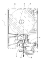
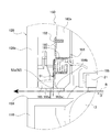
- FIG. 1 is a cross-sectional view showing a configuration of an image forming apparatus of Embodiment 1.
- FIG. 1 is an exploded perspective view showing a configuration of a cutter device of Example 1;
- FIG. 1 is a cross-sectional view showing a cutter device of Example 1;
- It is a perspective view which shows the structure of the rear cover of Example 1, and shows the state to which the static elimination brush was attached.
- FIG. 7 is an enlarged cross-sectional view of a protrusion of the rear cover of Example 1;
- FIG. 7 is a configuration diagram showing a configuration of a biasing portion of a rear cover of Example 1;
- FIG. 7 is an enlarged cross-sectional view of a biasing portion of the rear cover of the first embodiment.
- FIG. 6 is a cross-sectional view showing the configuration of the image forming apparatus of Example 2; It is sectional drawing which expands and shows the protrusion part of Example 2.
- FIG. 6 is a cross-sectional view showing the configuration of the image forming apparatus of Example 2; It is sectional drawing which expands and shows the protrusion part of Example 2.
- the image forming apparatus in the first embodiment is applied to a thermal printer.
- FIG. 1 is a perspective view showing a state in which the cover of the image forming apparatus of Embodiment 1 is closed.
- FIG. 2 is a perspective view showing a state in which the cover of the image forming apparatus of Embodiment 1 is opened.
- FIG. 3 is a cross-sectional view showing the configuration of the image forming apparatus of the first embodiment. The configuration of the image forming apparatus of the first embodiment will be described below based on FIGS. 1 to 3.
- the image forming apparatus 1 includes a main body 10 and a cover 20 which can be opened and closed with respect to the main body.
- the main body 10 includes a roll paper holding unit 12 for holding the roll paper 11, a platen roller 13 for supporting the paper supplied from the roll paper, and a cutter device 50 for cutting the paper. And.
- the roll paper holding unit 12 rotatably holds the roll paper 11.
- the roll paper 11 is a continuous paper in which thermal paper is wound in a roll, and supplies the paper to the conveyance path R.
- the platen roller 13 is disposed downstream of the roll paper 11 in the paper conveyance direction D.
- the platen roller 13 supports the sheet supplied from the roll sheet 11 from the back side in the image forming operation.
- the cutter device 50 is disposed downstream of the platen roller 13 in the sheet conveyance direction D.
- the cover 20 is provided with a thermal head unit 21.
- the thermal head unit 21 is disposed to face the platen roller 13 when the cover 20 is closed.
- the thermal head unit 21 is urged in a direction in contact with the platen roller 13 to form a nip N.
- the thermal head unit 21 performs thermal printing on the sheet at the nip N.
- the sheet supplied from the roll sheet 11 is conveyed to the nip N.
- the thermal head unit 21 performs thermal printing on the sheet conveyed to the nip N.
- the sheet subjected to the thermal printing is cut by the cutter device 50 and discharged from the discharge port 59.
- FIG. 4 is an exploded perspective view showing the configuration of the cutter device of the first embodiment.
- FIG. 5 is a cross-sectional view showing the cutter device of the first embodiment.
- the configuration of the cutter device of the first embodiment will be described based on FIGS. 4 and 5.
- the cutter device 50 is, as shown in FIGS. 4 and 5, a discharger brush 51 as a discharger, a rear cover 60 as an attachment member to which the discharger brush 51 is attached, and a cutter frame to which a fixed blade 56a and a movable blade 56b are attached. 55, a cutter motor 57 attached to the cutter frame 55, and a front cover 58.
- the static elimination brush 51 has a brush portion 52 as a static elimination portion and a conductive sheet 53 as a support portion for supporting the brush portion 52.
- the brush unit 52 is made of, for example, a SUS material, and has a plurality of flexible hair bundles 52a arranged at equal intervals in the width direction E of the sheet orthogonal to the sheet conveyance direction D. Each hair bundle 52a is set to a predetermined hair bundle density.
- the hair bundle 52 a constitutes the tip of the static elimination brush 51.
- the conductive sheet 53 extends in the width direction E and is formed in a band shape.
- the conductive sheet 53 can be a flexible and conductive sheet (for example, made of aluminum) (referred to as an aluminum tape).
- One end of the hair bundle 52a is attached to one surface of the conductive sheet 53 by a conductive double-sided tape.
- the conductive sheet 53 to which the hair bundle 52a is attached is attached to the later-described step portion 64 of the rear cover 60 with a double-sided tape.
- the static elimination brush 51 is attached to the stepped portion 64 such that a part of the brush portion 52 protrudes into the conveyance path R.
- the brush unit 52 contacts the sheet transported to the transport path R, and removes the charge on the sheet.
- the rear cover 60 is integrally formed by resin molding. The configuration of the rear cover 60 will be described later.
- the cutter frame 55 is formed by processing a conductive sheet of iron, aluminum, stainless steel or the like.
- the cutter frame 55 is composed of a blade mounting portion 55a as a facing member and a motor housing portion 55b.
- the blade attachment portion 55 a is formed in a plate shape and extends in the width direction E.
- the blade attachment portion 55 a is provided downstream of the static elimination brush 51 attached to the rear cover 60 in the transport direction D so as to face the static elimination brush 51.
- the fixed blade 56a is attached to the upper portion of the blade attachment portion 55a.
- the movable blade 56b is attached to the lower part of the blade attachment portion 55a.
- the fixed blade 56a is disposed to face the movable blade 56b.
- the movable blade 56b is connected to the cutter motor 57 via a gear, and operates up and down. By moving the movable blade 56b, the sheet conveyed to the cutter device 50 is cut.
- the motor accommodating portion 55b is formed in a box shape so as to cover a part of the blade attaching portion 55a below the blade attaching portion 55a, and accommodates the cutter motor 57 inside.
- An earth wire (not shown) is connected to the cutter frame 55, and is grounded via the earth wire.
- the front cover 58 is internally provided with an accommodating portion 58 a that accommodates the cutter frame 55, the cutter motor 57, and the discharging brush 51. Further, the front cover 58 is provided with a discharge port 59 for discharging the sheet.
- the rear cover 60 is attached to the front cover 58 so as to cover the front cover 58 in a state where the static elimination brush 51, the cutter frame 55, and the cutter motor 57 are accommodated in the housing portion 58a of the front cover 58. Then, two screws 91 are attached from the outside of the front cover 58 and one screw 91 is attached from the outside of the rear cover 60, whereby the cutter device 50 is assembled.
- FIG. 6 is a perspective view showing the configuration of the rear cover of the embodiment 1, and shows a state in which the discharging brush 51 is attached.
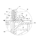
- FIG. 7 is an enlarged cross-sectional view of the protrusion of the rear cover of the first embodiment.
- FIG. 8 is a block diagram showing the biasing portion of the rear cover of the first embodiment.
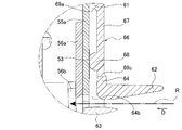
- FIG. 9 is an enlarged sectional view of a biasing portion of the rear cover of the first embodiment.
- the rear cover 60 is integrally formed by resin molding, and the upper cover 62 and the lower guide for guiding the conveyed sheet into the cutter device 50 with the rear cover main body 61 and the conveyance path R interposed vertically.
- the upper guide 62 is provided on the upper side of the conveyance path R so as to extend in the direction opposite to the conveyance direction D, as shown in FIG.
- the lower surface of the upper guide 62 is composed of a first lower surface 62 a substantially parallel to the transport direction D and a second lower surface 62 b inclined with respect to the transport direction D.
- the lower guide 63 is provided on the lower side of the conveyance path R so as to extend in the direction opposite to the conveyance direction D.
- the upper surface of the lower guide 63 is composed of a first upper surface 63 a substantially parallel to the conveyance direction D and a second lower surface 63 b inclined with respect to the conveyance direction D.
- the lower guide 63 extends longer than the upper guide 62 in the direction opposite to the transport direction D.
- the rear cover 60 has a step 64 recessed from the rear cover main body 61 in the direction opposite to the transport direction D, as shown in FIGS. 6 and 7.
- the static elimination brush 51 is attached to the step 64. That is, the static elimination brush 51 is attached to the step portion 64 disposed upstream of the static elimination brush 51 in the transport direction D.
- the lower end of the step portion 64 is formed to face the transport path R.
- a gap is formed between the blade attachment portion 55 a of the cutter frame 55 and the discharging brush 51 attached to the stepped portion 64 in the transport direction D.
- the gap is formed to open toward the conveyance path R.
- the discharging brush 51 is pressed by the sheet conveyed to the conveyance path R, and in a state of being in contact with the sheet, it is bent at this gap.
- the rear cover 60 has a projecting portion 65 that protrudes from the lower end of the step portion 64 in the transport direction D toward the blade attachment portion 55a.
- a plurality of projecting portions 65 are provided at equal intervals in the width direction E.
- the lower surface 65a of the projecting portion 65 is substantially parallel to the sheet conveyance direction D, and is the same surface as the first lower surface 62a.
- the protrusion 65 may be in contact with the blade attachment portion 55a.
- the protruding portion 65 restricts the sheet from entering the gap between the blade attachment portion 55 a and the static elimination brush 51.
- the protrusions 65 are provided at the same intervals as the intervals at which the hair bundles 52a of the static elimination brush 51 are provided, and do not come in contact with the hair bundles 52a. In addition, the protrusion part 65 and the hair bundle 52a do not need to be equal intervals, and the protrusion part 65 does not need to contact the hair bundle 52a.
- a corner R portion 64b rounded at a corner is formed at an angle portion formed by the surface 64a of the step portion 64 to which the discharging brush 51 is attached and the first lower surface 62a of the upper guide 62. That is, the first lower surface 62a is connected to the lower surface 65a of the projecting portion 65 in the portion having the projecting portion 65 in the width direction E, and is connected to the corner R portion 64b in the portion having no projecting portion 65 in the width direction E .
- the corner formed by the surface 64a of the step 64 to which the discharging brush 51 is attached and the first lower surface 62a of the upper guide 62 may be chamfered in a planar manner.
- the static elimination brush 51 is attached to the step portion 64 and the urging portion 66 described later by a double-sided tape, and the hair bundle 52 a of the static elimination brush 51 is ejected to the conveyance path R.
- the biasing portion 66 is provided at one end in the width direction E of the rear cover 60, as shown in FIG.
- the biasing portion 66 includes an elastic portion 67 having elasticity and a convex portion 68 provided at the tip of the elastic portion 67.
- the elastic portion 67 is provided at an opening 69 provided at one end of the rear cover 60 in the width direction E.
- the opening 69 is formed to straddle the rear cover main body 61 and the step 64.
- the opening 69 is formed in a rectangular shape, and the base end of the elastic portion 67 is connected to the top surface 69 a of the opening.
- the biasing portion 66 is not connected to the side surface 69 b and the bottom surface 69 c of the opening 69, and a slit is formed between the biasing portion 66 and the side surface 69 b and the bottom surface 69 c of the opening 69.
- the convex portion 68 protrudes from the tip of the elastic portion 67 in the transport direction D toward the blade attachment portion 55 a.
- the convex portion 68 is in contact with the blade attachment portion 55a.
- the convex portion 68 may be designed to interfere with the blade attachment portion 55a.
- the static elimination brush 51 is attached to the rear cover 60 configured in this way.
- the operator affixes the end of the conductive sheet 53 of the static elimination brush 51 to the convex portion 68 of the biasing portion 66.
- the worker sticks the conductive sheet 53 to the step 64.
- the elastic portion 67 may have a flat surface to which the conductive sheet 53 is attached.
- the conductive sheet 53 attached to the elastic portion 67 is urged toward the blade attachment portion 55a by the urging portion 66, and the conductive sheet 53 is in a state of always in contact with the blade attachment portion 55a.
- the image forming apparatus 1 is provided with a conveyance path R for conveying a sheet, and a portion protruding from the conveyance path R for discharging charges by contacting the sheet conveyed to the conveyance path R.
- the discharging unit (the discharging brush 51) is pressed against the sheet to be transported.
- the tip (hair bundle 52a) of the static elimination brush 51) bends and contacts the sheet. Therefore, the discharging means (the discharging brush 51) can be reliably brought into contact with the sheet, and the reliability of the discharging of the charge on the sheet can be improved.
- a regulating portion protruding portion 65 for regulating the sheet from entering the gap between the discharging means (the discharging brush 51) and the opposing member (the blade attaching portion 55a)
- the sheet is prevented from entering the gap. be able to. Therefore, occurrence of paper jam can be prevented.
- the static elimination brush By raising the transport path, the static elimination brush can be bent in the transport path without having a gap between the static elimination means and the opposing member. The reason is that the length of the hair bundle extending into the transport path is long, and the hair bundle is easily bent.
- the transport path is made high, there is a problem that the leading end of the sheet is rounded in the transport path and the sheet is not discharged from the discharge port.
- the height of the discharge port is increased in order to discharge the sheet which has been rolled in the transport path, there is a problem that the user puts a finger in the discharge port.
- such a problem is solved by providing a restricting portion that restricts the sheet from entering the gap between the charge removing unit and the facing member.
- the charge removing device (the charge removing brush 51) is attached to the attachment member (rear cover 60) disposed upstream or downstream of the charge removing device (the charge removing brush 51) in the transport direction D. ) Is a projection which protrudes from the mounting member (rear cover 60) toward the opposing member (the blade mounting portion 55a) (FIG. 7).
- the restricting portion (projecting portion 65) can be formed on the mounting member (rear cover 60) without providing a separate part. Therefore, the number of parts can be reduced.
- the restricting portion (projecting portion 65) is provided at a position not in contact with the tip portion (hair bundle 52a) of the static elimination unit (static charge brush 51) (FIG. 6).
- the hair bundle 52a of the discharging unit (the discharging brush 51) is spaced apart and disposed so as to avoid the regulating portion (the projecting portion 65). Therefore, the static elimination means (static elimination brush 51) can be easily attached to the attachment member (rear cover 60) in a state where the static elimination means (static elimination brush 51) does not interfere with the regulating portion (projecting portion 65).
- the tip portions (hair bundle 52a) of the discharging unit (the discharging brush 51) are arranged at equal intervals in the width direction E, and the regulating units (projections 65) are arranged at equal intervals in the width direction E ( Figure 6).
- the mounting member (rear cover 60) is provided on the upper side of the conveyance path R, and is provided on the lower side of the conveyance path R and an upper guide (upper guide 62) extending in the direction opposite to the conveyance direction D. And a lower guide (lower guide 63) extending in the direction opposite to the transport direction D, and the upper guide (upper guide 62) and the lower guide (lower guide 63) are attachment members (rear cover 60). And one-piece molding (Fig. 5).
- the upper guide (upper guide 62) and the lower guide (lower guide 63) can be formed on the mounting member (rear cover 60) without providing separate components. Therefore, the number of parts can be reduced.
- the lower surface of the protrusion 65 is substantially flush with the lower surface of the upper guide (upper guide 62) (FIG. 7).
- the corner formed by the surface of the mounting member (rear cover 60) to which the discharging means (the discharging brush 51) is attached and the lower surface of the upper guide (upper guide 62) is chamfered (FIG. 7).
- the discharging means (the discharging brush 51) can be largely bent in the direction opposite to the conveying direction D. Therefore, the discharging means (the discharging brush 51) can be made to inhibit the reverse running of the sheet as much as possible.
- a conductive metal piece and a metal made of a metal that presses this metallic piece to the static elimination brush in contact with the static elimination brush There is one configured by using a pressing member.
- the pressing member is further connected to a metal part such as a metal bracket grounded by a ground wire.
- the charge removing unit (the charge removing brush 51) is conductive and supports the charge removing unit (brush unit 52) in contact with the sheet and the charge removing unit (brush unit 52).
- the mounting member (rear cover 60) includes a biasing portion 66 having a biasing force toward the conductive opposing member (the blade mounting portion 55a), A part of the support portion (conductive sheet 53) is attached to the biasing portion 66 (FIG. 9).
- the support portion (conductive sheet 53) of the discharging means (the discharging brush 51) can be brought into contact with the opposing member (the blade mounting portion 55a) which is a conductive metal material by the biasing portion 66. Therefore, the charge carried by the discharging means (the discharging brush 51) can be released to the opposing member (the blade attachment portion 55a) by discharging the sheet with a small number of parts and a simple configuration.
- the mounting member (rear cover 60) is made of resin, and the biasing portion 66 is directed toward the opposing member (the blade mounting portion 55a) at the elastic portion 67 having elasticity and the tip of the elastic portion 67. And a protruding protrusion 68 (FIG. 9).
- the biasing portion 66 can be easily formed by resin molding. Therefore, the biasing portion 66 can be formed on the mounting member (rear cover 60) without providing a separate part, and the number of parts can be reduced.
- the biasing portion 66 is provided at the end of the support portion (conductive sheet 53) in the width direction E (FIG. 6).
- one end of the support portion (conductive sheet 53) can be attached to the biasing portion 66. Therefore, the biasing force of the biasing unit 66 can be utilized.
- the biasing portion is provided at, for example, the central portion of the support portion
- the conductive sheet attached to the step portion with double-sided tape or the like holds down the biasing portion in a state of being retracted from both sides. As a result, there is a problem that the biasing force of the biasing unit does not act.
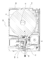
- FIG. 10 is a cross-sectional view showing the configuration of the image forming apparatus of the second embodiment.
- FIG. 11 is an enlarged cross-sectional view of the protrusion of the second embodiment.
- the configuration of the image forming apparatus of the second embodiment will be described based on FIGS. 10 and 11.
- FIG. The same or equivalent parts as the contents described in the first embodiment will be described using the same terms or the same reference numerals.
- the image forming apparatus 101 according to the second embodiment is different from the image forming apparatus according to the first embodiment in that the image forming apparatus 101 according to the second embodiment mainly includes no cutter device.
- the thermal head unit 21 includes an upper frame 160 to which various components such as a print head are attached.
- the upper frame 160 is a resin component, and as shown in FIG. 11, has a frame wall 160a as an attachment member disposed opposite to the front wall 120a of the cover 120 as an opposite member.
- the lower end of the frame wall 160 a is formed to face the transport path R.
- a gap is formed between the front wall 120 a and the discharging brush 51 attached to the frame wall 160 a via a ground plate 180 described later.
- the gap is formed to open toward the conveyance path R.
- the discharging brush 51 is pressed by the sheet conveyed to the conveyance path R, and in a state of being in contact with the sheet, it is bent at this gap.
- the upper frame 160 has a protrusion 165 as a restricting portion that protrudes toward the front wall 120 a in the transport direction D from the lower end of the frame wall 160 a.
- a plurality of projecting portions 165 are provided at equal intervals in the width direction E shown in the first embodiment.
- the lower surface 165a of the projecting portion 165 is substantially parallel to the sheet conveyance direction D, and is in the same plane as the lower surface 162a of the frame wall 160a.
- the protrusion 165 may abut on the front wall 120a.
- the projecting portion 165 is provided in the width direction E at the same interval as the interval at which the hair bundle 52a of the static elimination brush 51 is provided, and does not contact the hair bundle 52a.
- the protrusion part 165 and the hair bundle 52a do not need to be provided at equal intervals, and the protrusion part 165 does not need to contact the hair bundle 52a.
- a corner R-portion 164b rounded at a corner is formed at the corner between the surface of the frame wall 160a to which the static elimination brush 51 is attached and the lower surface 162a of the frame wall 160a. That is, the lower surface 162a of the frame wall 160a is connected to the lower surface 165a of the projecting portion 165 in the portion where the projecting portion 165 is in the width direction E, and is connected to the corner R portion 164b in the portion where the projecting portion 165 is not in the width direction E Be done.
- the corner formed by the surface of the frame wall 160a to which the discharging brush 51 is attached and the lower surface 162a of the frame wall 160a may be chamfered in a planar manner.
- the outer surface of the cover 120 and the lower surface facing the transport path R of the cover 120 form a corner on the upper side of the discharge port 159.
- the outer surface of the lower case 110 and the upper surface facing the conveyance path R of the lower case 110 form a corner below the discharge port 159. The user can cut the sheet discharged from the discharge port 159 by pressing it against either the upper or lower corner of the discharge port 159.
- Attached to the upper frame 160 are a ground plate 180 to which the static elimination brush 51 is attached, a ground spring 181 which is an elastic body contacting the ground plate, a head bracket 195 for supporting the head, and the like.
- the ground plate 180 is formed of a conductive metal in a plate shape.
- the static elimination brush 51 is attached to the ground plate 180 by a conductive double-sided tape.
- the static elimination brush 51 attached to the ground plate 180 is attached to the ground plate 180 such that a part of the brush portion 52 protrudes into the transport path R.
- the brush unit 52 contacts the sheet transported to the transport path R, and removes the charge on the sheet.
- the ground plate 180 is attached to the upper frame 160 by screws 192.
- the upper frame 160 has a housing portion 161 for housing the ground spring 181.
- the ground spring 181 is formed of a conductive and elastic metal in a linear shape.
- the ground spring 181 has one end in contact with the ground plate 180 and the other end extending linearly in the direction opposite to the transport direction in contact with the head bracket 195.
- the head bracket 195 is formed of conductive metal.
- the head bracket 195 is connected to a ground wire (not shown) and grounded.
- the present invention can be applied to a configuration that does not have a cutter device, and exhibits the same effects as the first embodiment.
- the projecting portions 65 and 165 are provided on the mounting member (rear cover 60, frame wall 160a) provided on the upstream side of the discharging brush 51 in the transport direction D is shown.
- the protrusion may be provided on the opposing member provided downstream of the static elimination brush 51 in the transport direction D.
- the plurality of projecting portions 65 and 165 may be united by connecting members in the width direction E by a connecting member, and may be formed as a separate component from the mounting member and the opposing member. In this case, the plurality of unitized projections are fixed to at least one of the attachment member and the opposing member.
- Example 1 and Example 2 the example which provides multiple protrusion parts 65 and 165 in the width direction E was shown. However, at least one protrusion may be provided in the width direction E. At least at the portion where the protruding portions 65 and 165 are provided, the effect of preventing the occurrence of paper jam can be obtained.
- the protruding portions 65 and 165 can be provided in the necessary number according to the position where paper jam is likely to occur, the frequency of the paper jam, and the like.
- Example 1 and Example 2 the example which provides the opposing member arrange
- an opposing member may be provided upstream of the static elimination means with a gap between the static elimination means, and in the transport direction D, upstream and downstream of the static elimination means in the transport direction D
- An opposing member may be provided to be disposed.
- the conductive sheet 53 to which the discharging brush 51 is attached may be directly attached to the upstream side wall surface in the transport direction D of the front wall 120a.
- the front wall 120 a is configured as a mounting member disposed downstream of the static elimination brush 51 in the transport direction D.
- the front wall 120a is also a facing member, and a large corner R portion is formed at a corner formed by the affixing surface of the conductive sheet 53 of the front wall 120a and the lower surface facing the transport path R of the front wall 120a.
- a gap is formed between the hair bundle 52a and the corner R portion.
- the hair bundle 52a can be sufficiently deformed in the transport direction D by the gap between the hair bundle 52a and the corner R portion.
- the protrusions 165 can be provided on either the front wall 120a or the frame wall 160a.
- the frame wall 160a disposed on the upstream side of the static elimination brush 51 in the transport direction D may be disposed with a gap from the static elimination brush 51 as another opposing member.
- the protrusion 165 is formed in the gap between the frame wall 160 a and the static elimination brush 51.
- Example 1 and Example 2 the example which uses a static elimination brush as a static elimination brush was shown.
- the static elimination means one having a conductive non-woven fabric formed in a comb shape may be used. That is, even if it does not have a brush shape, it may be one that contacts the sheet conveyed to the conveyance path R and deforms between the charge removing unit and the opposing member to such an extent that the conveyance of the sheet is not impeded.
- the blade mounting portion 55a, the front wall 120a, the frame wall 160a, and the like are opposed as the opposing members over the entire area in the longitudinal direction of the static elimination unit.
- the opposing member may be opposed to a part of the static elimination means in the longitudinal direction.
- Example 1 the example which provides several static elimination means equally to the width direction E was shown.
- the discharging means may not be evenly arranged.
- Example 1 and Example 2 the example which arrange
- the discharging means may be arranged to project upward from the lower side of the transport path.
- the charge removing means, the opposing member, and the protrusion are also provided on the lower side of the transport path.
- Example 1 and Example 2 the static elimination means showed the example which has the some hair bundle 52a.
- a hair bundle can be made into various shapes, for example, you may form in strip shape.
- the image forming apparatus is applied to a thermal printer.
- the image forming apparatus can be applied to an impact type printer, a laser printer, an ink jet printer, and the like.
Landscapes
- Engineering & Computer Science (AREA)
- Mechanical Engineering (AREA)
- Feeding Of Articles By Means Other Than Belts Or Rollers (AREA)
- Handling Of Continuous Sheets Of Paper (AREA)
- Accessory Devices And Overall Control Thereof (AREA)
- Electronic Switches (AREA)
- Elimination Of Static Electricity (AREA)
Applications Claiming Priority (2)
| Application Number | Priority Date | Filing Date | Title |
|---|---|---|---|
| JP2017249119A JP7066400B2 (ja) | 2017-12-26 | 2017-12-26 | 画像形成装置 |
| JP2017-249119 | 2017-12-26 |
Publications (1)
| Publication Number | Publication Date |
|---|---|
| WO2019131009A1 true WO2019131009A1 (ja) | 2019-07-04 |
Family
ID=67067234
Family Applications (1)
| Application Number | Title | Priority Date | Filing Date |
|---|---|---|---|
| PCT/JP2018/044507 Ceased WO2019131009A1 (ja) | 2017-12-26 | 2018-12-04 | 画像形成装置 |
Country Status (2)
| Country | Link |
|---|---|
| JP (1) | JP7066400B2 (enExample) |
| WO (1) | WO2019131009A1 (enExample) |
Families Citing this family (1)
| Publication number | Priority date | Publication date | Assignee | Title |
|---|---|---|---|---|
| JP7789558B2 (ja) * | 2021-12-28 | 2025-12-22 | シャープ株式会社 | 画像形成装置 |
Citations (4)
| Publication number | Priority date | Publication date | Assignee | Title |
|---|---|---|---|---|
| JP2001100535A (ja) * | 1999-09-28 | 2001-04-13 | Kyocera Mita Corp | 画像形成装置の除電装置 |
| JP2004213952A (ja) * | 2002-12-27 | 2004-07-29 | Kyocera Mita Corp | 除電部材の取り付け構造 |
| JP2005335902A (ja) * | 2004-05-27 | 2005-12-08 | Fuji Xerox Co Ltd | 除電装置及び画像形成装置 |
| JP2016099426A (ja) * | 2014-11-19 | 2016-05-30 | 富士ゼロックス株式会社 | 除電装置及び画像形成装置 |
Family Cites Families (1)
| Publication number | Priority date | Publication date | Assignee | Title |
|---|---|---|---|---|
| JP4366024B2 (ja) * | 2001-03-16 | 2009-11-18 | キヤノン株式会社 | 画像形成装置 |
-
2017
- 2017-12-26 JP JP2017249119A patent/JP7066400B2/ja active Active
-
2018
- 2018-12-04 WO PCT/JP2018/044507 patent/WO2019131009A1/ja not_active Ceased
Patent Citations (4)
| Publication number | Priority date | Publication date | Assignee | Title |
|---|---|---|---|---|
| JP2001100535A (ja) * | 1999-09-28 | 2001-04-13 | Kyocera Mita Corp | 画像形成装置の除電装置 |
| JP2004213952A (ja) * | 2002-12-27 | 2004-07-29 | Kyocera Mita Corp | 除電部材の取り付け構造 |
| JP2005335902A (ja) * | 2004-05-27 | 2005-12-08 | Fuji Xerox Co Ltd | 除電装置及び画像形成装置 |
| JP2016099426A (ja) * | 2014-11-19 | 2016-05-30 | 富士ゼロックス株式会社 | 除電装置及び画像形成装置 |
Also Published As
| Publication number | Publication date |
|---|---|
| JP2019112209A (ja) | 2019-07-11 |
| JP7066400B2 (ja) | 2022-05-13 |
Similar Documents
| Publication | Publication Date | Title |
|---|---|---|
| US8899742B2 (en) | Image recording apparatus | |
| US20080143046A1 (en) | Sliding Mechanism, sheet guide, sheet loading device, and image forming apparatus | |
| JP2015034066A (ja) | 搬送装置 | |
| CN107323105B (zh) | 打印装置 | |
| WO2019131009A1 (ja) | 画像形成装置 | |
| CN107393226B (zh) | 打印装置 | |
| JPH072209Y2 (ja) | プリンタ | |
| US20180345690A1 (en) | Printer | |
| JP2002120419A (ja) | 紙送り機構及びこの紙送り機構を用いた画像記録装置 | |
| US7552920B2 (en) | Paper feed cassette | |
| CN104070848A (zh) | 记录装置 | |
| JP2012171728A (ja) | カッター装置およびこれを備えるプリンター | |
| CN109835748B (zh) | 纸卷支架 | |
| US20110074094A1 (en) | Sheet feeder and image recording apparatus | |
| JP6185244B2 (ja) | 用紙ガイド機構 | |
| JP2013001528A (ja) | シート支持装置 | |
| JP7565813B2 (ja) | ラベルプリンタ | |
| CN209971908U (zh) | 印字装置 | |
| US9073371B1 (en) | Cutter apparatus and printer | |
| JP4207041B2 (ja) | 用紙ガイド装置及び画像形成装置 | |
| JPH0789069A (ja) | インクジェットプリンタ | |
| JP2002008890A (ja) | 除電ユニット | |
| JPS61173971A (ja) | 紙送装置 | |
| JP4151504B2 (ja) | 給紙装置 | |
| US8813619B2 (en) | Cutting assembly with ejector posts |
Legal Events
| Date | Code | Title | Description |
|---|---|---|---|
| 121 | Ep: the epo has been informed by wipo that ep was designated in this application |
Ref document number: 18894642 Country of ref document: EP Kind code of ref document: A1 |
|
| NENP | Non-entry into the national phase |
Ref country code: DE |
|
| 122 | Ep: pct application non-entry in european phase |
Ref document number: 18894642 Country of ref document: EP Kind code of ref document: A1 |