WO2019130987A1 - 押しボタンスイッチ - Google Patents
押しボタンスイッチ Download PDFInfo
- Publication number
- WO2019130987A1 WO2019130987A1 PCT/JP2018/044229 JP2018044229W WO2019130987A1 WO 2019130987 A1 WO2019130987 A1 WO 2019130987A1 JP 2018044229 W JP2018044229 W JP 2018044229W WO 2019130987 A1 WO2019130987 A1 WO 2019130987A1
- Authority
- WO
- WIPO (PCT)
- Prior art keywords
- plunger
- lever
- movable
- housing
- movable direction
- Prior art date
- Legal status (The legal status is an assumption and is not a legal conclusion. Google has not performed a legal analysis and makes no representation as to the accuracy of the status listed.)
- Ceased
Links
Images






Classifications
-
- H—ELECTRICITY
- H01—ELECTRIC ELEMENTS
- H01H—ELECTRIC SWITCHES; RELAYS; SELECTORS; EMERGENCY PROTECTIVE DEVICES
- H01H3/00—Mechanisms for operating contacts
- H01H3/02—Operating parts, i.e. for operating driving mechanism by a mechanical force external to the switch
- H01H3/022—Emergency operating parts, e.g. for stop-switch in dangerous conditions
-
- H—ELECTRICITY
- H01—ELECTRIC ELEMENTS
- H01H—ELECTRIC SWITCHES; RELAYS; SELECTORS; EMERGENCY PROTECTIVE DEVICES
- H01H13/00—Switches having rectilinearly-movable operating part or parts adapted for pushing or pulling in one direction only, e.g. push-button switch
- H01H13/02—Details
- H01H13/12—Movable parts; Contacts mounted thereon
- H01H13/14—Operating parts, e.g. push-button
-
- H—ELECTRICITY
- H01—ELECTRIC ELEMENTS
- H01H—ELECTRIC SWITCHES; RELAYS; SELECTORS; EMERGENCY PROTECTIVE DEVICES
- H01H13/00—Switches having rectilinearly-movable operating part or parts adapted for pushing or pulling in one direction only, e.g. push-button switch
- H01H13/02—Details
- H01H13/10—Bases; Stationary contacts mounted thereon
-
- H—ELECTRICITY
- H01—ELECTRIC ELEMENTS
- H01H—ELECTRIC SWITCHES; RELAYS; SELECTORS; EMERGENCY PROTECTIVE DEVICES
- H01H13/00—Switches having rectilinearly-movable operating part or parts adapted for pushing or pulling in one direction only, e.g. push-button switch
- H01H13/02—Details
- H01H13/04—Cases; Covers
-
- H—ELECTRICITY
- H01—ELECTRIC ELEMENTS
- H01H—ELECTRIC SWITCHES; RELAYS; SELECTORS; EMERGENCY PROTECTIVE DEVICES
- H01H13/00—Switches having rectilinearly-movable operating part or parts adapted for pushing or pulling in one direction only, e.g. push-button switch
- H01H13/02—Details
- H01H13/26—Snap-action arrangements depending upon deformation of elastic members
- H01H13/36—Snap-action arrangements depending upon deformation of elastic members using flexing of blade springs
- H01H13/44—Snap-action arrangements depending upon deformation of elastic members using flexing of blade springs having two or more snap-action motions in succession
-
- H—ELECTRICITY
- H01—ELECTRIC ELEMENTS
- H01H—ELECTRIC SWITCHES; RELAYS; SELECTORS; EMERGENCY PROTECTIVE DEVICES
- H01H13/00—Switches having rectilinearly-movable operating part or parts adapted for pushing or pulling in one direction only, e.g. push-button switch
- H01H13/50—Switches having rectilinearly-movable operating part or parts adapted for pushing or pulling in one direction only, e.g. push-button switch having a single operating member
- H01H13/52—Switches having rectilinearly-movable operating part or parts adapted for pushing or pulling in one direction only, e.g. push-button switch having a single operating member the contact returning to its original state immediately upon removal of operating force, e.g. bell-push switch
-
- H—ELECTRICITY
- H01—ELECTRIC ELEMENTS
- H01H—ELECTRIC SWITCHES; RELAYS; SELECTORS; EMERGENCY PROTECTIVE DEVICES
- H01H3/00—Mechanisms for operating contacts
- H01H3/02—Operating parts, i.e. for operating driving mechanism by a mechanical force external to the switch
- H01H3/04—Levers
-
- H—ELECTRICITY
- H01—ELECTRIC ELEMENTS
- H01H—ELECTRIC SWITCHES; RELAYS; SELECTORS; EMERGENCY PROTECTIVE DEVICES
- H01H3/00—Mechanisms for operating contacts
- H01H3/02—Operating parts, i.e. for operating driving mechanism by a mechanical force external to the switch
- H01H3/20—Operating parts, i.e. for operating driving mechanism by a mechanical force external to the switch wherein an auxiliary movement thereof, or of an attachment thereto, is necessary before the main movement is possible or effective, e.g. for unlatching, for coupling
-
- H—ELECTRICITY
- H01—ELECTRIC ELEMENTS
- H01H—ELECTRIC SWITCHES; RELAYS; SELECTORS; EMERGENCY PROTECTIVE DEVICES
- H01H3/00—Mechanisms for operating contacts
- H01H3/02—Operating parts, i.e. for operating driving mechanism by a mechanical force external to the switch
- H01H3/022—Emergency operating parts, e.g. for stop-switch in dangerous conditions
- H01H2003/0246—Resetting of bistable emergency operating part by rotating itself or an accessory
-
- H—ELECTRICITY
- H01—ELECTRIC ELEMENTS
- H01H—ELECTRIC SWITCHES; RELAYS; SELECTORS; EMERGENCY PROTECTIVE DEVICES
- H01H9/00—Details of switching devices, not covered by groups H01H1/00 - H01H7/00
- H01H9/08—Arrangements to facilitate replacement of a switch, e.g. cartridge housing
Definitions
- the present disclosure relates to a push button switch having a lock lever portion.
- Patent Document 1 discloses an operation including a contact portion having a B contact, an operation portion for opening and closing the B contact of the contact portion, and a lock mechanism having a lock lever capable of mutually fixing the operation portion and the contact portion.
- a switch is disclosed.
- the lock lever is provided with a cam that rotates in conjunction with the turning operation of the lock lever, and the B contact of the contact portion is configured to be able to open and close by this cam.
- the operation portion is fixed to the contact portion by moving the lock lever to the complete lock position in a state where one end portion of the operation portion is fitted in the attachment hole provided in the contact portion.
- the contact is configured to switch from the off state to the on state.
- the operation portion is attached to the contact portion in a state of being inclined with respect to the contact portion or in a state where one end of the operation portion is sufficiently inserted into the attachment hole of the contact portion
- the incomplete attachment state of the operation unit can not be determined from the outside, and the performance and safety of the operation switch may not be ensured.
- An object of the present disclosure is to provide a push button switch that can securely attach an operating unit in a complete state.
- An example push button switch of the present disclosure is: A housing having an operation surface provided with an operation hole, and an accommodating portion provided inside and connected to the operation hole; It is provided in the inside of the storage part, and can move between a return position away from the operation surface and an intermediate operation position between the operation surface and the return position along a movable direction intersecting the operation surface.
- the housing extends from the outside of the housing to the inside of the housing through the operation hole along the movable direction, and is attached to the housing with the end on the housing side in the extending direction positioned at the initial position And a pressing surface provided on the outside of the housing and disposed to face the operation surface, and the pressing surface is capable of approaching the operation surface along the movable direction.
- an operation unit for moving the end portion on the accommodation unit side from the initial position to the pressed position by the approach operation to position the plunger at the return position;
- a lever body exposed to the outside of the housing and movable in a direction intersecting the movable direction between the first position and the second position, and provided inside the receiving portion so as to be movable with the lever body
- a lock lever portion having a lever support portion connected to the lever body, and a holding portion capable of holding the lever body at the second position; It is provided between the lock lever portion and the plunger inside the housing portion, and the plunger is returned along the movable direction as the lever body moves from the first position toward the second position.
- Transmission mechanism for moving the plunger from the operating position to the return position along the movable direction as the lever body moves from the second position to the first position while moving from the position to the operating position Department,
- the end portion of the operation unit on the side of the accommodation portion is provided between the operation portion and the lock lever portion inside the accommodation portion and the lever main body is positioned at the first position.
- the lock lever portion having the lever main body movable between the first position and the second position, the holding portion capable of holding the lever main body at the second position, and the lever main body Transfer to move the plunger from the return position to the operating position as it moves from the position to the second position, while moving the plunger from the operating position to the return position as the lever body moves from the second position to the first position While the mechanism portion and the lever main body are located at the first position, the lever main body can be moved to the second position when the end portion on the accommodation portion side of the operation portion is located at the initial position A movement restricting portion that makes it impossible to move the lever main body to the second position when the end of the operation portion on the accommodation portion side is positioned closer to the operation surface than the initial position; And a first biasing portion for biasing toward a return position from.
- the lever main body in the push button switch, for example, when attaching the operation unit once removed for maintenance or the like to the housing, the lever main body is at the second position when the end on the accommodation unit side of the operation unit is positioned at the initial position.
- the lever main body can be moved to the second position when the end of the operation unit on the side of the storage unit is positioned closer to the operation surface than the initial position in the movable direction while being movable and held by the holding unit.
- the lever body is biased by the first biasing unit via the plunger to move to the first position.
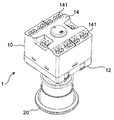
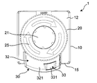
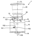
- FIG. 1 is a perspective view of a push button switch according to an embodiment of the present disclosure.
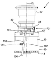
- FIG. 2 is a perspective view of the push button switch of FIG. 1 as viewed from a direction different from FIG. 1.
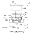
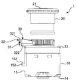
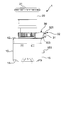
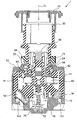
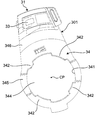
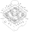
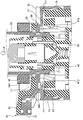
- the front view of the push button switch of FIG. FIG. 2 is a right side view of the push button switch of FIG. 1; The left view of the push button switch of FIG. The top view of the push button switch of FIG. The bottom view of the push button switch of FIG. Sectional drawing along the VIII-VIII line of FIG.
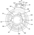
- the front view of the operation part of the push button switch of FIG. The bottom view of the operation part and lock lever part of the push button switch of FIG.
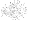
- the top view of the lever part of the push button switch of FIG. FIG. 6 is a perspective view of a part of the housing of the push button switch of FIG. 1 and the operation unit 20;
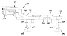
- the right view of the lever part of the push button switch of FIG. The perspective view of the plunger of the push button switch of FIG.
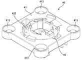
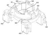
- the perspective view of the 1st plunger of the push button switch of FIG. The perspective view of the 2nd plunger of the push button switch of FIG.
- FIG. 19 is a first plan view seen from the direction of arrow A in FIG. 18 for explaining the operation of the transmission mechanism of the push button switch in FIG. 1;
- FIG. 19 is a second plan view seen from the direction of arrow A in FIG.
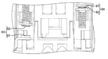
- FIG. 10 is a first plan view for explaining the operation of the contact mechanism portion of the push button switch of FIG. 1;
- FIG. 7 is a second plan view for explaining the operation of the contact mechanism portion of the push button switch of FIG. 1;
- FIG. 10 is a first front view for explaining the operation of the lever main body 31 using the jig of the push button switch of FIG. 1; The 2nd front view for demonstrating operation of the lever main body 31 using the jig
- the push button switch 1 according to the embodiment of the present disclosure is exposed to the outside of the substantially cubic housing 10, the operation unit 20 attached to the housing 10, and the housing 10 as shown in FIGS. 1 to 7. And a lock lever portion 30 provided on the
- the housing 10 has an operation surface 12 provided with an operation hole 13.
- the operation hole 13 has, for example, a substantially circular shape.
- the operation unit 20 extends from the outside to the inside of the housing through the operation hole 13 in a movable direction (hereinafter, simply referred to as a movable direction) intersecting (for example, orthogonal to) the operation surface 12, and the extending direction
- a movable direction hereinafter, simply referred to as a movable direction
- the lock lever portion 30 is disposed at the edge of the operation surface 12 of the housing 10.
- a housing portion 11 connected to the operation hole 13 is provided inside the housing 10. That is, one end portion in the extension direction of the operation unit 20 is disposed inside the storage unit 11.
- a plunger 40 having a first plunger 41 and a second plunger 42, a transmission mechanism portion 50 (shown in FIGS. 19 and 20), a contact mechanism portion 60, and a biasing portion 70. It is provided.
- the plunger 40 is disposed at the end on the operation surface 12 side in the movable direction of the housing portion 11, and the biasing portion 70 is on the end on the terminal connection surface 14 side facing the operation surface 12 in the movable direction of the housing portion 11. It is arranged. Further, the transmission mechanism unit 50 and the contact mechanism unit 60 are disposed between the plunger 40 and the biasing unit 70.
- the housing 10 has a terminal connection surface 14 facing the operation surface 12 and four side surfaces extending in a direction (for example, an orthogonal direction) intersecting the operation surface 12 and the terminal connection surface 14. And one of four side surfaces constitutes the fulcrum forming surface 15.
- the fulcrum forming surface 15 is provided with a fulcrum protrusion 151 projecting from the fulcrum forming surface 15 toward the outside of the housing 10 along a direction (for example, an orthogonal direction) intersecting the fulcrum forming surface 15.
- the fulcrum protrusion 151 has an oval shape extending in the direction orthogonal to the movable direction as viewed from the direction orthogonal to the fulcrum forming surface 15, and has the operation surface 12 and the terminal connection surface 14. , And one side of the center of the fulcrum forming surface 15 in the direction orthogonal to the movable direction.
- the fulcrum projection 151 extends in the movable direction of the operation portion 20 passing the centers of the first position P1 and the second position P2 in the movement direction of the lever main body 31 when viewed from the direction orthogonal to the fulcrum forming surface 15 It is disposed on the first position P1 side with respect to the line CL (see FIGS. 24 and 25).
- one curved surface 152 in the extending direction thereof is the first lever main body 31 of the lock lever portion 30 described later using the long jig 100 (see FIGS. 24 and 25).
- the tip end portion 101 which is one end of the jig 100 contacts the intermediate portion 102 of the jig 100 locked to the locking portion 312 of the lock lever 30 described later.
- the curved surface 152 is provided at a portion in contact with the intermediate portion 102 of the jig 100 and protrudes from the fulcrum projection 151 toward the jig 100.
- the terminal connection surface 14 is provided with a plurality of openings 141.
- Each of the openings 141 is configured, for example, such that a conductor of a wire (not shown) can be inserted, and is connected to the terminal connection mechanism 16 provided inside the housing 11 as shown in FIG.
- this terminal connection mechanism 16 adopts a so-called push-in connection type, and is configured such that the conductor of the wire can be connected to the push button switch 1 simply by inserting the conductor of the wire from the opening 141 It is done.
- the operation unit 20 has a substantially cylindrical shape, and a pressing surface 21 provided outside the housing 10 and disposed to face the operation surface 12.
- the operation unit 20 is configured to be capable of approaching operation in which the pressing surface 21 approaches the operation surface 12 along the movable direction, and the plunger 40 is positioned at a return position P3 (see FIG. 19) described later by this approaching operation. Is configured as. Specifically, when the plunger 40 is at the non-return position other than the return position P3 (more specifically, the second plunger 42 is at the non-return position other than the return position P32), the operation portion 20 receives the operation portion 20 by the approaching operation. The end 22 on the side of the portion 11 moves from the initial position (shown in FIG. 8) to the pressed position, and the plunger 40 is returned along the movable direction to the return position P3 (more specifically, the second plunger 42 is returned along the movable direction) Move to position P32).
- the pressing surface 21 is provided with a display unit 25 that indicates the rotational direction of the operating unit 20 when the operating unit 20 is attached to the housing 10.
- the display unit 25 is configured by a clockwise arrow when viewed from the approaching direction in which the pressing surface 21 in the movable direction approaches the operation surface 12 (hereinafter simply referred to as the approaching direction).
- a second groove 24 is provided which is connected to the U-shaped portion 231 and extends along the circumferential direction of the end 22 of the operation portion 20 on the side of the accommodation portion 11.
- the first groove portion 23 and the second groove portion 24 are configured to be able to accommodate a locking projection 342 provided on a lock lever portion 30 described later.
- the first groove portion 23 can accommodate the locking projection 342 when the lever main body 31 is positioned at the first position P1, and the second groove portion 24 is a lever main body as shown in FIG.
- the locking projection 342 is configured to be capable of being locked in the movable direction when the position 31 is in the second position P2.
- the locking projection 342 of the lock lever 30 and the first groove 23 and the second groove 24 of the operation unit 20 constitute a movement restricting portion 80.
- the movement restricting portion 80 when the lever main body 31 is positioned at the first position P1, the end 22 on the accommodation portion 11 side of the operation portion 20 is at the initial position (that is, as shown in FIG. 9)
- the portion 342 is located at the end portion 22 side of the operation portion 20 on the accommodation portion 11 side when the first groove portion 23 is located at the end portion 231 on the pressing surface 21 side in the movable direction
- the lever main body 31 when the end 22 of the operation unit 20 on the side of the storage unit 11 is positioned closer to the operation surface 12 than the initial position in the movable direction. Restrict movement to position P2 and make it impossible.
- the operation unit 20 is rotated only in one direction (in the embodiment, the direction of the arrow of the display unit 25).
- the first groove 23 and the second groove 24 are connected so as to be able to do so. That is, the movement restricting portion 80 is provided between the operation portion 20 and the lock lever portion 30 inside the accommodation portion 11 and depends on whether or not the lever main body 31 can be moved to the second position P2. It can be checked whether or not 20 is securely attached to the housing 10.
- a display 26 that indicates the mounting direction of the operation unit 20 to the housing 10 (in this embodiment, the housing 11 Arrows in the direction towards the end 22 of the side are provided.
- the lock lever portion 30 includes a lever portion 301 and an exterior portion 32 fixed to the housing 10 so as to cover the lever portion 301.
- the lever portion 301 has a lever main body 31 exposed to the outside of the housing 10 and a lever support portion 34 disposed in the housing portion 11, as shown in FIG.
- the lever main body 31 intersects (for example, is orthogonal to) the fulcrum forming surface 15 from the fulcrum forming surface 15 as shown in FIG. 7 and protrudes in the direction away from the fulcrum forming surface 15 as shown in FIG. It is disposed between the pressing surface 21 and the operation surface 12 in the movable direction.
- the lever main body 31 is a direction (for example, orthogonal to the movable direction between the first position P1 (see FIG. 24) and the second position P2 (see FIG. 25) when viewed from the direction orthogonal to the fulcrum forming surface 15.
- Direction is configured to be movable.
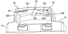
- the exterior portion 32 is an upper surface in the movable direction of the lever main body 31 (that is, an opposing surface 311 (shown only in FIG. 7) facing the operation surface 12 of the lever main body 31).
- the second wall 322 and the third wall 323 are connected to the first wall 321 and the operation surface 12 of the housing 10, respectively.
- the movement range of the lever main body 31 is defined by the exterior portion 32.
- a holding portion 33 capable of holding the lever main body 31 at the second position P2 is provided at one end (that is, the right end in FIG. 6) of the first wall 321 in the extending direction. ing.
- the holding portion 33 holds the lever main body 31 by pressing the lever main body 31 from one side to the other in the movable direction (that is, from the upper side of FIG. 11) at the second position P2.
- It has a possible elastic holding part 331.
- the elastic holding portion 331 extends in the extending direction of the first wall portion 321, and the end portion 332 of the other end side of the first wall portion 321 in the extending direction (that is, the left side in FIG.
- the end portion 333 connected to the first wall portion 321 and at one end side of the first wall portion 321 in the extending direction is disposed between the first wall portion 321 and the operation surface 12, and the operation surface in the movable direction It is configured to be elastically deformable in the direction away from 12.
- a display unit 37 is provided on the first position P1 side (that is, the left side in FIG. 11) of the surface of the first wall 321 facing the operation surface 12.
- the display unit 37 is configured of the characters "UNLOCK" and an arrow indicating a direction from the second position P2 to the first position P1.
- a locking portion 312 and a holding release portion 313 are provided on the opposite surface 311 of the lever main body 31.
- the locking portion 312 is a tip end portion 101 which is one end portion of the elongated jig 100 used for moving the lever main body 31 from the first position P1 to the second position P2 (see FIGS. 25 and 26). ) Can be locked.
- the holding release unit 313 presses the lever main body 31 from the other side in the movable direction to one side in the second position P2 (that is, from the front to the back in the paper surface penetrating direction of FIG. 7) 31 is configured to be able to be released.
- lever main body 31 is disposed on the opposite side of the fulcrum forming surface 15 to the holding releasing portion 313 (that is, the upper side in FIG. 7) in the direction intersecting the fulcrum forming surface 15 and intersects the fulcrum forming surface 15
- a protective wall portion 314 is provided which protects the holding release portion 313 in the direction.
- the lock lever portion 30 has a lever support portion 34 movably connected to the lever main body 31 with the lever main body 31.
- the lever support portion 34 is provided inside the housing portion 11 as shown in FIG. 13 and surrounds the end 22 on the housing portion 11 side of the operation portion 20 in the circumferential direction (that is, around the movable direction), An inner circumferential surface 341 of the lever support portion 34 is disposed to face an end 22 of the operation portion 20 on the accommodation portion 11 side.
- the lever support portion 34 is provided with a locking projection 342 which protrudes from the inner peripheral surface 341 toward the operation portion 20 (that is, inward in the radial direction of the lever support portion 34). It is done.
- four locking protrusions 342 are arranged at intervals in the circumferential direction of the inner circumferential surface 341 of the lever support 34.
- the lever support portion 34 is configured of a lever connection portion 345 and an inclined portion 346 as an example of the connection portion.
- the lever connection portion 345 has a substantially annular shape and extends along the operation surface 12, and the end portion 22 of the storage portion 11 of the operation portion 20 is accommodated in the substantially circular through hole portion 344 at the central portion thereof. It is done. That is, the lever main body 31 is pivoted about a pivoting axis which passes through the center of the lever connection portion 345 and extends in the movable direction.
- the lever connection portion 345 is connected to the operation portion 20 so as to be movable in the movable direction together with the operation portion 20 when the lever main body 31 is at the second position P2.
- the inclined portion 346 is connected to the lever connection portion 345 and the lever main body 31 and is separated from the operation surface 12 toward the pressing surface 21 along the movable direction as it goes from the lever connection portion 345 to the lever main body 31 It is inclined in the opposite direction).
- the lever connection portion 345 is provided with a plurality of cam protrusions 343 (two cam protrusions 343 as an example in this embodiment) projecting radially outward from the outer peripheral surface of the lever support 34 .
- each cam projection 343 is provided on the outer peripheral surface 351 of a pair of legs 35 extending in the direction away from the operation surface 12 along the movable direction from the edge of the through hole 344 of the lever connection portion 345 .
- each cam projection 343 has a rectangular shape in which all corner portions are chamfered, as viewed from the projecting direction.
- Each leg 35 is disposed on the same straight line passing through the center CP (shown in FIG. 12) of the through hole 344, and each cam projection 343 corresponds to each of a plurality of cam grooves 412 of the first plunger 41 described later. Are engageable with each other.
- the lever support portion 34, the plurality of cam projections 343, and the plurality of cam groove portions 412 constitute the transmission mechanism portion 50. That is, the transmission mechanism unit 50. It is disposed between the lock lever portion 30 and the plunger 40.
- the lever main body 31 is provided with a display portion 36 on an exposed side surface not covered by the exterior portion 32 when viewed from the direction orthogonal to the fulcrum forming surface 15.
- the display unit 36 is composed of the characters "LOCK" and an arrow indicating the direction from the first position P1 to the second position P2.
- the plunger 40 is disposed at the end of the housing 11 on the side of the operation surface 12 and is at a return position P3 (see FIG. 19) away from the operation surface 12 along the movable direction. It is configured to be movable between an operating position (see FIG. 20) between the operation surface 12 and the return position P3.
- the plunger 40 is disposed in series along the movable direction with respect to the substantially rectangular plate-like first plunger 41 and the first plunger 41 and is disposed away from the operation surface 12 And a second plunger 42 which is The first plunger 41 and the second plunger 42 are not connected, and are configured to be movable independently of each other.
- the first plunger 41 is provided in a substantially central portion and has a substantially circular through hole 411 penetrating in the movable direction, and is provided on the inner circumferential surface 414 of the through hole 411 and has an inner periphery And a plurality of cam grooves (in this embodiment, two cam grooves as an example in this embodiment) 412 which are spaced apart from each other (for example, 180 degrees apart) in the circumferential direction of the surface 414. .
- the end 22 of the operation unit 20 on the side of the storage unit 11 is rotatably accommodated in the through hole 411 in the circumferential direction of the inner circumferential surface 414 (that is, around the movable direction). ing.
- Each cam groove portion 412 moves closer to the operation surface 12 as it travels clockwise along the circumferential direction of the inner peripheral surface 414 of the through hole portion 411 as viewed from the approaching direction (in other words, the first of the lever main bodies 31 Are disposed so as to be separated from the operation surface 12 along the moving direction from the position P1 to the second position P2 and are engageable with the respective cam protrusions 343 of the lever support portion 34 of the lock lever portion 30. It is done. That is, the inner circumferential surface 414 of the through hole 411 faces the outer circumferential surface 351 of each leg 35 of the lever support 34, and each cam groove 412 corresponds to each cam projection 343. Further, at each corner of the first plunger 41, a circular recess 413 is provided. In each recess 413, as shown in FIG. 13, a coil spring 71 is accommodated.
- the second plunger 42 has an annular main body portion 421 provided with a through hole 423 at the center portion, and a plurality of plunger connection portions provided radially outward of the main body portion 421 (this In the embodiment, four plunger connections 422 are provided as an example.
- the main body portion 421 is provided with an annular wall portion 424 projecting in the direction approaching the operation surface 12 along the movable direction (that is, upward in FIG. 17) from the peripheral edge portion of the through hole portion 423 at the central portion.
- the annular wall portion 424 is configured to be insertable into the through hole portion 411 of the first plunger 41.
- a partially annular recess 425 in which the end 22 on the accommodation portion 11 side of the operation unit 20 is accommodated is formed on the radially outer side of the annular wall 424 of the main body 421.
- the respective plunger connection portions 422 are arranged at intervals along the circumferential direction of the outer peripheral surface of the main body portion 421.
- Each plunger connecting portion 422 has a substantially rectangular parallelepiped shape extending in the direction away from the operation surface 12 along the movable direction from the main body portion 421 (that is, downward in FIG. 17), and is connected to the contact mechanism portion 60.
- the LED unit 90 is disposed in the through hole 423 of the second plunger 42.
- FIG. 18 to FIG. 19 is a plan view seen from the direction indicated by arrow A in FIG. 18 in which the lever main body 31 is at the first position P1 and the plunger 40 is at the return position P3.
- FIG. FIG. 19 is a plan view seen from the direction indicated by arrow A in FIG. 18 in a state in which the plunger 40 is in the two position P2 and in the operating position P4.
- the first plunger 41 moves from the return position P31 to the operation position P41
- the lever main body 31 is moved from the second position P2 to the first position P1
- it is moved from the operating position P41 to the return position P31.
- the second plunger 42 is biased in a direction approaching the operation surface 12 along a movable direction by a coil spring 72 described later. Therefore, the second plunger 42 moves from the return position P32 to the operating position P42 along with the movement of the first plunger 41 from the return position P3 to the operating position P4, and returns from the operating position P4 of the first plunger 41 to the return position P3.
- the movement from the operation position P42 to the return position P32 is performed along with the movement to the
- the second plunger 42 is configured to be movable to the return position P32 along the movable direction by the approaching operation of the operation unit 20. That is, the second plunger 42 is configured to be positioned at the return position P32 by the approach operation of the operation unit 20.
- the second plunger 42 is moved to the return position P32 by the approaching operation of the operation unit 20, the second plunger 42 is held at the return position P32 by the end 22 of the operation unit 20 on the accommodation portion 11 side.
- the transmission mechanism unit 50 moves the plunger 40 along the movable direction from the return position P3 to the operation position P4 as the lever body 31 moves from the first position P1 to the second position P2, while the lever body 31 Moves the plunger 40 from the operating position P4 to the return position P3 along the movable direction as it moves from the second position P2 toward the first position P1.
- the transmission mechanism unit 50 has a function of transmitting the moving operation of the lever main body 31 to the plunger 40.
- the contact mechanism section 60 respectively opposes the plurality of fixed contact sections 61 provided inside the accommodation section 11 and each fixed contact section 61 in the movable direction inside the accommodation section 11. And a plurality of movable contact portions 62 provided.
- Each fixed contact portion 61 is connected to the terminal connection mechanism portion 16 respectively.
- Each movable contact portion 62 is connected to any one of the four plunger connection portions 422 of the second plunger 42, and contacts the fixed contact portion 61 opposed by the movement from the return position P32 of the second plunger 42 to the operation position P42. , And is separated from the stationary contact portion 61 in contact by the movement of the second plunger 42 from the operating position P42 to the return position P32.
- the contact mechanism portion 60 is configured to be opened and closed by the movement of the second plunger 42 along the movable direction.
- the terminal connection mechanism parts 16 are arranged in line along the surface facing the fulcrum forming surface 15 and the fulcrum forming surface 15 respectively.
- the fixed contact portion 61 connected to the terminal connection mechanism portion 16 (hereinafter referred to as the first terminal connection mechanism portion 161) disposed along the fulcrum forming surface 15 and the opposed movable contact portion 62 constitute an NO contact 63.
- the fixed contact portion 61 connected to the terminal connection mechanism portion 16 (hereinafter referred to as a second terminal connection mechanism portion 162) disposed along the surface facing the fulcrum forming surface 15 and the opposed movable contact portion 62 are NCs.
- the contact 64 is configured. That is, as shown in FIG.
- the biasing unit 70 has a coil spring 71 (shown in FIG. 13) as an example of a first biasing unit and a coil spring 72 (shown in FIG. 8) as an example of a second biasing unit.
- the coil springs 71 are respectively disposed in recesses 413 provided at the four corners of the first plunger 41 inside the housing portion 11 and return the plunger 40 from the operating position P4 along the movable direction. Energize toward P3. Specifically, each coil spring 71 is sandwiched by the bottom surface of the recess 413 of the first plunger 41 and the inner surface 111 (see FIG. 24) constituting the housing portion 11 of the housing 10 facing the bottom surface. The plunger 41 is pressed in a direction away from the operation surface 12 along the movable direction, and the first plunger 41 is arranged in a state of being biased from the operating position P41 toward the return position P31.
- each coil spring 71 is disposed so that the pressure applied to the first plunger 41 is equalized, and the lever main body 31 of the lock lever portion 30 is moved from the second position P2 to the first position P1 via the first plunger 41. I'm turning towards.
- the coil spring 72 is disposed between the terminal connection surface 14 and the contact mechanism 60 along the movable direction inside the housing 11 as shown in FIG. 8 to return the plunger 40 along the movable direction P3. To the operation position P4. Specifically, the coil spring 72 is disposed on the center line CL extending in the movable direction of the operation unit 20, and presses the portion of the contact mechanism 60 facing the terminal connection surface 14 toward the operation surface 12 to make the contact mechanism
- the second plunger 42 is arranged to be biased from the return position P32 toward the operation position P42 along the movable direction via the portion 60.
- the coil spring 71 is configured such that its biasing force is greater than the biasing force of the coil spring 72.
- the wall 18 on the operation surface 12 side of the housing 10 is provided with a deformation 17 that is connected to the exterior 32 of the lock lever 30 and extends along the slope 346 of the lever support 34. It is done.
- the inclined portion 346 of the lever support portion 34 moves toward the operation portion 20 and contacts the deformation portion 17 of the housing 10.
- the inclined portion 346 in contact with the deforming portion 17 deforms in the approaching direction, moves the lever main body 31 in the approaching direction, and releases the pressing on the lever main body 31 by the holding portion 33.
- the lever main body 31 is moved from the second position P2 to the first position P1 by the coil spring 71, and the movable contact portion 62 of the NC contact 64 is fixed correspondingly. It separates from the contact portion 61.
- the distal end portion 101 of the jig 100 is locked to the locking portion 312 of the lever main body 31 at the first position P1.
- the jig 100 is disposed such that the intermediate portion 102 contacts the curved surface 152 of the fulcrum protrusion 151.
- the lever body 31 can be moved from the first position P 1 to the second position P 2 using the jig 100.
- the first plunger 41 and the first plunger 41 can move the plunger 40 between the return position P 3 and the operation position P 4 by the transmission mechanism 50 of the lock lever 30.
- a second plunger 42 which is disposed farther from the operation surface 12 than the first plunger 41 and is movable to the return position P3 by the operation unit 20.
- the first plunger 41 and the second plunger 41 can move independently of each other, and the movable contact portion 62 contacts or separates from the fixed contact portion 61 by the movement of the second plunger 42. It is configured.
- the movable contact with respect to the fixed contact portion 61 can be achieved only by securing the position accuracy of the second plunger 42 and the contact mechanism portion 50 without being influenced by securing of the position accuracy of the lock lever portion 30.
- the contact reliability of the portion 62 can be secured. Therefore, for example, the contact reliability of the fixed contact portion 61 and the movable contact portion 62 is improved as compared with the operation switch of Patent Document 1 that needs to ensure the positional accuracy of the lock lever, the cam, the holder, and the B contact. It can be secured easily.
- the first plunger 41 is provided in the through hole 411 penetrating in the movable direction and in the inner circumferential surface 414 of the through hole 411 and is arranged to be spaced apart from each other in the circumferential direction of the inner circumferential surface 414,
- the lock lever portion 30 includes a plurality of through holes 411.
- the plurality of cam grooves 412 are each inclined to be separated from the operation surface 12 along the moving direction from the first position P1 to the second position P2 of the lever main body 31.
- the transmission mechanism unit 50 includes a plurality of cam groove portions 412, a lever support portion 34, and a plurality of cam projection portions 343. The transmission mechanism 50 can move the entire plunger 40 more reliably along the movable direction, so that the contact reliability between the fixed contact 61 and the movable contact 62 can be secured.
- the lever main body 31 of the lock lever portion 30 has the locking portion 312 capable of locking the one end portion 101 of the elongated jig 100 in the extending direction, and the housing 10 is When moving the lever main body 31 of the lock lever portion 30 from the first position P1 to the second position P2 using the jig 100, the intermediate portion 102 of the jig 100 in which the one end portion 101 is locked by the locking portion 312. And a fulcrum projection 151 which is a fulcrum of the jig 100 in contact therewith.
- the holding portion 33 has an elastic holding portion 331 capable of holding the lever main body 31 by pressing the lever main body 31 from the one side in the movable direction to the other at the second position P2, and the lever main body 31 has the second position P2.
- a holding release portion 313 capable of releasing the holding of the lever main body 31 by the elastic holding portion 331 by pressing the lever main body 31 from the other side in the movable direction to one side.
- the lever main body 31 is disposed on the opposite side of the fulcrum forming surface 15 to the holding releasing portion 313 in the direction intersecting the fulcrum forming surface 15 and protects the holding releasing portion 313 in the direction intersecting the fulcrum forming surface 15
- a protective wall portion 314 is provided. The protective wall portion 314 can reduce the erroneous operation of the holding release portion 313.
- a fulcrum protrusion 151 is provided at a portion in contact with the intermediate portion 102 of the jig 100, and has a curved surface 152 projecting toward the jig 100 from the fulcrum protrusion 151.
- the curved fulcrum 152 makes the turning fulcrum of the jig 100 constant, and the lever body 31 can be more easily operated using the jig 100.
- the fulcrum protrusion 151 is disposed closer to the first position P1 than the centers of the first position P1 and the second position P2 in the movement direction of the lever main body 31 when viewed from the direction orthogonal to the fulcrum forming surface 15. .
- the lever body 31 can be more easily operated using the jig 100.
- the lever support portion A deformation portion 17 is provided to move the lever main body 31 in contact with the movable portion 34 and to release the pressing on the lever main body 31 by the holding portion 33 so as to deform the lever main body 31.
- the lever main body 31 is disposed between the pressing surface 21 and the operation surface 12 in the movable direction, and the lever support portion 34 extends along the operation surface 12 so that the lever main body 31 is at the second position P2.
- the lever connection portion 345 is connected to the lever connection portion 345 and the lever main body 31 which are connected to the operation portion 20 so as to be movable in the movable direction together with the operation portion 20 in some cases.
- the deformation portion 17 is disposed to face the inclined portion 346 so as to be in contact therewith, and when the operation portion 20 is pulled in the separation direction, the deformation portion 17 contacts the inclined portion 346 to move the lever main body 31 in the approaching direction.
- the lever main body 31 is deformed so as to be able to release the pressing on the lever main body 31 by the holding portion 33.
- the operation portion 20 is separated from the housing 10. Even if the movable contact portion 62 is pulled in the opening direction, the holding of the lever main body 31 by the holding portion 33 can be released more reliably, and the movable contact portion 62 can be separated from the fixed contact portion 61.
- the lock lever portion has the lever main body 31 movable between the first position P1 and the second position P2, and the holding portion 33 capable of holding the lever main body 31 at the second position P2. 30 and as the lever main body 31 moves from the first position P1 to the second position P2, the plunger 40 is moved from the return position P3 to the operating position P4, while the lever main body 31 moves from the second position P2 to the first position P1.
- the transmission mechanism 50 moves the plunger 40 from the operating position P4 to the return position P3 as it moves toward the
- the end 22 is located at the initial position
- movement of the lever body 31 to the second position P2 is enabled, while the end 2 of the operation unit 20 on the side of the storage unit 11 Is located on the operation surface 12 side of the initial position, the movement restricting portion 80 which makes it impossible to move the lever main body 31 to the second position P2, and the plunger 40 from the operation position P4 toward the return position P3.
- a coil spring 71 for biasing.
- the push button switch 1 for example, when attaching the operation unit 20 once removed for maintenance or the like to the housing 10, when the end 22 on the accommodation unit 11 side of the operation unit 20 is positioned at the initial position
- the main body 31 can be moved to the second position P2 and held by the holding portion 33, while the end 22 on the accommodation portion 11 side of the operation portion 20 is positioned closer to the operation surface 12 than the initial position in the movable direction.
- the lever main body 31 can not be moved to the second position P2, and the lever main body 31 is biased by the first biasing portion 71 via the plunger 40 to move to the first position P1. This makes it possible to realize the push button switch 1 capable of securely attaching the operating unit 20 in a complete state.
- the coil spring 72 is further provided inside the housing portion 11 and urges the plunger 40 from the return position P3 toward the operation position P4 along the movable direction, and the biasing force of the coil spring 71 is the coil spring 72. It is configured to be larger than the biasing force of The plunger 40 is disposed so as to be capable of being biased by the coil spring 71, and along with the movement of the lever main body 31 between the first position P1 and the second position P2, the transmission mechanism portion 50 returns the return position P31 and A first plunger 41 movable in the movable direction between operating positions P41, and a position which can be biased by a coil spring 72 and is spaced apart from the operation surface 12 along the movable direction than the first plunger 41 and
- the second plunger 42 is disposed in series along the movable direction with respect to the one plunger 41, and is located at the return position P32 by the approach operation of the operation unit 20.
- first plunger 41 and the second plunger 42 can be moved independently of each other along the movable direction, and the movable contact portion 62 can be fixed contact portion 61 by the movement of the second plunger 42 along the movable direction.
- the contact reliability of the movable contact portion 62 with respect to the fixed contact portion 61 can be obtained only by securing the position accuracy of the second plunger 42 and the contact mechanism portion 50 without being influenced by the securing of the position accuracy of the lock lever portion 30. Can be secured.
- the first plunger 41 is provided in the through hole 411 penetrating in the movable direction and in the inner circumferential surface 414 of the through hole 411 and is arranged to be spaced apart from each other in the circumferential direction of the inner circumferential surface 414, And a plurality of cam groove portions 412 which are respectively inclined so as to be separated from the operation surface 12 along the moving direction from the first position P1 to the second position P2 of the lever main body 31; And extends along the inner circumferential surface 414 of the through hole 411 and is provided corresponding to each of the plurality of cam grooves 412, and is provided with an outer periphery facing the inner circumferential surface 414 of the lever support portion 34.
- the transmission mechanism unit 50 includes a plurality of cam groove portions 412, a lever support portion 34, and a plurality of cam projection portions 343.
- the transmission mechanism 50 can move the entire plunger 40 more reliably along the movable direction, so that the contact reliability between the fixed contact 61 and the movable contact 62 can be secured.
- lever support portion 34 surrounds the end 22 of the operation portion 20 on the accommodation portion 11 side in the circumferential direction (that is, around the movable direction), and the inner circumferential surface 341 thereof is an end of the operation portion 20 on the accommodation portion 11 side.
- the locking portion 342 is disposed to face the portion 22 and has a locking projection 342 protruding from the inner circumferential surface 341 toward the operation portion 20, and the end 22 on the accommodation portion 11 side of the operation portion 20 is movable Connected to the first groove 23 capable of accommodating the locking projection 342 when the lever body 31 extends in the first position P1 and the end 231 on the pressing surface 21 side in the movable direction of the first groove 23
- the lock projection 342 is extended along the circumferential direction of the end 22 of the operation unit 20 on the storage unit 11 side, and locked in the movable direction when the lever main body 31 is at the second position P2.
- Second groove 24 for locking the protrusion 342 The has.
- the movement restricting portion 80 is configured by the locking projection 342, the first groove 23 and the second groove 24. As a result, the movement of the lever main body 31 to the second position can be restricted with a simple configuration, so that the push button switch 1 capable of reliably attaching the operation unit 20 in a complete state can be easily realized.
- the first biasing unit is configured of a plurality of coil springs 71.
- the plunger 40 can be biased from the operating position P4 toward the return position P3 along the movable direction with a simple configuration.
- the second biasing portion is constituted by at least one coil spring 72.
- the plunger 40 can be biased from the return position P3 toward the operation position P4 along the movable direction with a simple configuration.
- the components other than the housing 10, the plunger 40, the operation unit 20, the lock lever 30, the transmission mechanism 50, the movement restricting unit 80, the contact mechanism 60, and the first urging unit 71 are omitted if possible.
- the push button switch 1 may be replaced with one having a different configuration.
- the deformation portion 17 of the housing 10 and the fulcrum projection 151 may be omitted.
- the transmission mechanism 50 is not limited to the case where the transmission mechanism 50 includes the lever support 34, the plurality of cam projections 343, and the plurality of cam grooves 412.
- the transmission mechanism unit 50 moves the plunger 40 from the return position P3 to the operation position P4 as the lever main body 31 moves from the first position P1 to the second position P2, while the lever main body 31 moves from the second position P2 It is possible to adopt any configuration that can move the plunger 40 from the operating position P4 to the return position P3 as it moves toward the 1 position P1.
- the contact mechanism portion 60 is provided to face the fixed contact portion 61 and the fixed contact portion 61 in the movable direction, and contacts the fixed contact portion 61 when the plunger 40 moves from the return position P3 to the operation position P4. If the movable contact portion 62 is separated from the fixed contact portion 61 when the plunger 40 moves from the operating position P4 to the return position P4, a contact mechanism portion having any configuration can be adopted.
- the lever connection portion 345 of the lever support portion 34 is not limited to the substantially annular shape, and may be, for example, a semicircular shape.
- the holding portion 33 is not limited to the case of being configured by the elastic holding portion 331, and any configuration can be adopted as long as the lever main body 31 can be held at the second position P2. Further, the holding releasing unit 313 can be appropriately changed according to the configuration of the holding unit 33.
- the protective wall portion 314 may be provided not only on the lever main body 31 but also on the exterior portion 32, for example.
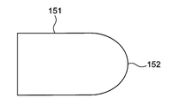
- the fulcrum protrusion 151 is not limited to the oval shape.
- it is a fulcrum protrusion 151 having a curved surface 152 only on the side in contact with the intermediate portion 102 of the jig 100 in the extending direction as seen from the direction orthogonal to the fulcrum forming surface 15.
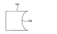
- a curved surface 152 in which the side in contact with the intermediate portion 102 of the jig 100 in the extension direction protrudes from the jig 100 in the direction orthogonal to the fulcrum forming surface 15.
- It may be a fulcrum projection 151 having the following.
- FIG. 27 it is a fulcrum protrusion 151 having a curved surface 152 only on the side in contact with the intermediate portion 102 of the jig 100 in the extending direction as seen from the direction orthogonal to the fulcrum forming surface 15.
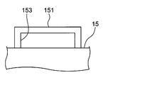
- the fulcrum projection 151 may be a fulcrum projection 151 having a through hole 153 penetrating in the movable direction.
- the inner peripheral surface of the through hole portion 153 contacts the intermediate portion 102 of the jig 100 and serves as a pivot of the jig 100.
- the first biasing unit is not limited to the case where the plurality of coil springs 71 are used, and may be any configuration capable of biasing the plunger 40 from the operating position P4 toward the return position P3 along the movable direction.
- the department can be adopted.
- the first biasing unit may be configured of a single or three or more coil springs 71.
- the second biasing portion is not limited to the case of being configured by a single coil spring 72, but may have any configuration capable of biasing the plunger 40 from the return position P3 toward the operation position P4 along the movable direction. It is possible to adopt the power section.
- the second biasing unit may be configured by a plurality of coil springs 72.
- the plunger 40 has a first plunger 41 and a second plunger 42 and may be movable between the return position P3 and the operation position P4 along the movable direction.
- the design can be changed as appropriate.
- the deformation portion 17 contacts the lever support portion 34 when the operation portion 20 is pulled in the separation direction in which the operation portion 20 is separated from the housing 10 when the lever main body 31 is positioned at the second position P2. , And the lever main body 31 may be deformed so as to be capable of releasing the pressing on the lever main body 31 by the holding portion 33. That is, the shape or the like of the deformation portion 17 can be appropriately changed in accordance with the shape or the like of the lever main body 31 and the lever support portion 34.
- the movement restricting portion 80 is not limited to the case where it is configured by the locking projection 342, the first groove 23 and the second groove 24.
- the movement restricting portion 80 is at the second position of the lever main body 31 when the end 22 on the accommodation portion 11 side of the operation portion 20 is positioned at the initial position. While movement to P2 is possible, when the end 22 of the operation unit 20 on the accommodation unit 11 side is positioned closer to the operation surface 12 than the initial position, movement of the lever main body 31 to the second position P2 is not performed. Any configuration that can be enabled can be employed.
- the push button switch 1 of the first aspect of the present disclosure is A housing 10 having an operation surface 12 provided with an operation hole 13 and a housing portion 11 provided inside and connected to the operation hole 13; A return position P3 provided inside the accommodation portion 11 and separated from the operation surface 12 along a movable direction intersecting the operation surface 12, and an operation position P4 between the operation surface 12 and the return position P3.
- a plunger 40 movable between the It extends along the movable direction from the outside of the housing 10 to the inside of the accommodation portion 11 through the operation hole 13 and the end 22 on the accommodation portion 11 side in the extending direction is located at the initial position It has a pressing surface 21 attached to the housing 10, provided outside the housing 10 and disposed to face the operation surface 12, and the pressing surface 21 extends along the movable direction.
- the end portion 22 on the accommodation portion 11 side is moved from the initial position to the pressed position by the approaching operation to position the plunger 40 at the return position P3.
- the operation unit 20 A lever main body 31 exposed to the outside of the housing 10 and movable in a direction crossing the movable direction between the first position P1 and the second position P2; A lock lever portion 30 having a lever supporting portion 34 movably connected to the main body 31 and the holding portion 33 capable of holding the lever main body 31 at the second position; It is provided between the lock lever portion 30 and the plunger 40 inside the accommodation portion 11, and the plunger 40 is moved as the lever main body 31 moves from the first position P1 toward the second position P2.
- the plunger 40 is moved along the movable direction as the lever main body 31 moves from the second position P2 toward the first position P1 while being moved from the return position P3 to the operation position P4 along the movable direction.
- the storage portion of the operation portion 20 is provided between the operation portion 20 and the lock lever portion 30 inside the storage portion 11 and the lever main body 31 is positioned at the first position P1.
- movement of the lever main body 31 to the second position P2 is enabled, while the end of the operation part 20 on the storage 11 side
- a movement restricting portion 80 which makes it impossible to move the lever main body 31 to the second position P2 when the movable body 22 is positioned closer to the operation surface 12 than the initial position in the movable direction;
- the fixed contact portion 61 provided in the interior of the accommodation portion 11 and the interior of the accommodation portion 11 are provided to face the stationary contact portion 61, and the plunger 40 is operated from the return position P3.
- a movable contact portion 62 which contacts the fixed contact portion 61 when moved to P2 and which is separated from the fixed contact portion 61 when the plunger 40 is moved from the operating position P3 to the return position P2
- a mechanism unit 60 A first biasing portion 71 is provided inside the storage portion 11, and biases the plunger 40 from the operating position P4 toward the return position P3 along the movable direction.
- the push button switch 1 of the first aspect for example, when attaching the operation unit 20 once removed for maintenance or the like to the housing 10, the end 22 on the accommodation unit 11 side of the operation unit 20 is located at the initial position At the same time, the lever main body 31 can be moved to the second position P2 and held by the holding portion 33, while the end 22 on the accommodation portion 11 side of the operation portion 20 is closer to the operation surface 12 than the initial position in the movable direction.
- the lever main body 31 can not be moved to the second position P2, and the lever main body 31 is biased to the first position P1 by the first biasing portion 71 via the plunger 40. .
- the push button switch 1 of the second aspect of the present disclosure is It further comprises a second biasing portion 72 provided inside the housing portion 11 and biasing the plunger 40 from the return position P3 toward the operation position P4 along the movable direction,
- the biasing force of the first biasing unit 71 is configured to be larger than the biasing force of the second biasing unit 72, and
- the plunger 40 is
- the return mechanism section 50 is configured to be biased by the first biasing section 71 and to be moved by the transmission mechanism section 50 along with the movement of the lever main body 31 between the first position P1 and the second position P2.
- the first plunger 41 is disposed apart from the operation surface 12 along the movable direction so as to be capable of being biased by the second biasing portion 72 and is arranged along the movable direction with respect to the first plunger 41.
- the second plunger 42 is disposed in series, and has a second plunger 42 positioned at the return position P3 by the approaching operation of the operation unit 20,
- the first plunger 41 and the second plunger 42 are movable independently of each other along the movable direction,
- the movable contact portion 62 is configured to be in contact with or separated from the fixed contact portion 61 by the movement of the second plunger 42 in the movable direction.
- the fixed contact portion 61 can be obtained only by securing the position accuracy of the second plunger 42 and the contact mechanism portion 50 without being influenced by the securing of the position accuracy of the lock lever portion 30.
- the contact reliability of the movable contact portion 62 with respect to the above can be secured.
- the push button switch 1 of the third aspect of the present disclosure is The first plunger 41 is From the first position P1 of the lever main body 31, provided on the inner circumferential surface 414 of the through hole 411 penetrating in the movable direction and spaced from each other in the circumferential direction of the inner circumferential surface 414, It has a plurality of cam groove portions 412 which are respectively inclined so as to be separated from the operation surface 12 along the movement direction toward the second position P2,
- the lever support 34 is It is disposed in the through hole 4111 and extends along the inner circumferential surface 414 of the through hole 411, and Each of the plurality of cam grooves 412 is provided to correspond to each of the plurality of cam grooves 412 and protrudes from the outer peripheral surface 351 facing the inner peripheral surface 414 of the lever support 34 toward the inner peripheral surface 414.
- a plurality of cam projections 343 respectively engaged with the respective cam grooves 412;
- the transmission mechanism unit 50 includes the plurality of cam groove portions 412, the lever support
- the entire plunger 40 can be moved more reliably along the movable direction by the transmission mechanism 50, the contact reliability of the fixed contact 61 and the movable contact 62 is achieved. Can be secured.
- the push button switch 1 of the fourth aspect of the present disclosure is
- the second biasing portion is constituted by at least one coil spring.
- the plunger 40 can be biased from the operating position P4 toward the return position P3 along the movable direction with a simple configuration.
- the push button switch 1 of the fifth aspect of the present disclosure is
- the first biasing unit is configured of a plurality of coil springs.
- the plunger 40 can be urged from the return position P3 toward the operation position P4 along the movable direction with a simple configuration.
- the push button switch 1 of the sixth aspect of the present disclosure is
- the lever support 34 is The end portion 22 of the operation portion 20 on the side of the accommodation portion 11 is surrounded around the movable direction, and the inner circumferential surface 341 thereof is disposed to face the end portion 22 on the accommodation portion 11 side of the operation portion 20 And has a locking projection 342 projecting from the inner circumferential surface 341 toward the operation portion 20,
- the end 22 of the operation unit 20 on the side of the housing 11 is: A first groove 23 capable of receiving the locking projection 342 when extending in the movable direction and the lever main body 31 is at the first position P1;
- the locking projection 342 is received along the circumferential direction of the end 22 of the operation portion 20 on the accommodation portion 11 side, which is connected to the end on the pressing surface 21 side in the movable direction of the first groove portion 23 And a second groove 24 for locking the locking projection 342 in the movable direction when the lever main body 31 is at the second position P2;
- the movement restricting portion 80 is
- the push button switch 1 of the sixth aspect since the movement of the lever main body 31 to the second position can be restricted with a simple configuration, the push button switch 1 capable of securely attaching the operation unit 20 in a complete state can be provided. It can be easily realized.
- the push button switch of the present disclosure can be applied to, for example, an emergency stop switch.
Landscapes
- Push-Button Switches (AREA)
- Rotary Switch, Piano Key Switch, And Lever Switch (AREA)
Abstract
Description
操作孔が設けられた操作面と、内部に設けられかつ前記操作孔に接続された収容部とを有するハウジングと、
前記収容部の内部に設けられ、前記操作面に交差する可動方向に沿って、前記操作面から離れた復帰位置と、前記操作面および前記復帰位置の中間の動作位置との間を移動可能なプランジャと、
前記ハウジングの外部から前記操作孔を介して前記収容部の前記内部まで前記可動方向に沿って延び、延在方向における収容部側の端部が初期位置に位置した状態で前記ハウジングに取り付けられていると共に、前記ハウジングの前記外部に設けられかつ前記操作面に対向するように配置された押圧面を有し、前記可動方向に沿って前記押圧面が前記操作面に対して接近動作可能であると共に、前記収容部側の端部が、前記接近動作によって前記初期位置から押圧位置まで移動して前記プランジャを前記復帰位置に位置させる操作部と、
前記ハウジングの外部に露出しかつ第1位置および第2位置の間を前記可動方向に交差する方向に移動可能なレバー本体と、前記収容部の前記内部に設けられて前記レバー本体と共に移動可能に前記レバー本体に接続されたレバー支持部と、前記レバー本体を前記第2位置で保持可能な保持部とを有するロックレバー部と、
前記収容部の内部で前記ロックレバー部と前記プランジャとの間に設けられ、前記レバー本体が前記第1位置から前記第2位置に向かって移動するにつれて前記プランジャを前記可動方向に沿って前記復帰位置から前記動作位置に移動させる一方、前記レバー本体が前記第2位置から前記第1位置に向かって移動するにつれて前記プランジャを前記可動方向に沿って前記動作位置から前記復帰位置に移動させる伝達機構部と、
前記収容部の内部で前記操作部と前記ロックレバー部との間に設けられ、前記レバー本体が前記第1位置に位置している場合において、前記操作部の前記収容部側の前記端部が前記初期位置に位置しているときには前記レバー本体の前記第2位置への移動を可能とする一方、前記操作部の前記収容部側の前記端部が前記可動方向において前記初期位置よりも操作面側に位置しているときには前記レバー本体の前記第2位置への移動を不可能とする移動規制部と、
前記収容部の前記内部に設けられた固定接点部と、前記収容部の前記内部で前記固定接点部に対向するように設けられ、前記プランジャが前記復帰位置から前記動作位置に移動した場合に前記固定接点部に接触し、前記プランジャが前記動作位置から前記復帰位置に移動した場合に前記固定接点部から開離する可動接点部とを有する接点機構部と、
前記収容部の内部に設けられ、前記プランジャを前記可動方向に沿って前記動作位置から前記復帰位置に向かって付勢する第1付勢部と
を備える。
操作孔13が設けられた操作面12と、内部に設けられかつ前記操作孔13に接続された収容部11とを有するハウジング10と、
前記収容部11の内部に設けられ、前記操作面12に交差する可動方向に沿って、前記操作面12から離れた復帰位置P3と、前記操作面12および前記復帰位置P3の中間の動作位置P4との間を移動可能なプランジャ40と、
前記ハウジング10の外部から前記操作孔13を介して前記収容部11の前記内部まで前記可動方向に沿って延び、延在方向における収容部11側の端部22が初期位置に位置した状態で前記ハウジング10に取り付けられていると共に、前記ハウジング10の前記外部に設けられかつ前記操作面12に対向するように配置された押圧面21を有し、前記可動方向に沿って前記押圧面21が前記操作面12に対して接近動作可能であると共に、前記収容部11側の前記端部22が、前記接近動作によって前記初期位置から押圧位置まで移動して前記プランジャ40を前記復帰位置P3に位置させる操作部20と、
前記ハウジング10の外部に露出しかつ第1位置P1および第2位置P2の間を前記可動方向に交差する方向に移動可能なレバー本体31と、前記収容部11の前記内部に設けられて前記レバー本体31と共に移動可能に前記レバー本体31に接続されたレバー支持部34と、前記レバー本体31を前記第2位置で保持可能な保持部33とを有するロックレバー部30と、
前記収容部11の内部で前記ロックレバー部30と前記プランジャ40との間に設けられ、前記レバー本体31が前記第1位置P1から前記第2位置P2に向かって移動するにつれて前記プランジャ40を前記可動方向に沿って前記復帰位置P3から前記動作位置P4に移動させる一方、前記レバー本体31が前記第2位置P2から前記第1位置P1に向かって移動するにつれて前記プランジャ40を前記可動方向に沿って前記動作位置P4から前記復帰位置P3に移動させる伝達機構部50と、
前記収容部11の内部で前記操作部20と前記ロックレバー部30との間に設けられ、前記レバー本体31が前記第1位置P1に位置している場合において、前記操作部20の前記収容部11側の前記端部22が前記初期位置に位置しているときには前記レバー本体31の前記第2位置P2への移動を可能とする一方、前記操作部20の前記収容部11側の前記端部22が前記可動方向において前記初期位置よりも前記操作面12側に位置しているときには前記レバー本体31の前記第2位置P2への移動を不可能とする移動規制部80と、
前記収容部11の前記内部に設けられた固定接点部61と、前記収容部11の前記内部で前記固定接点部61に対向するように設けられ、前記プランジャ40が前記復帰位置P3から前記動作位置P2に移動した場合に前記固定接点部61に接触し、前記プランジャ40が前記動作位置P3から前記復帰位置P2に移動した場合に前記固定接点部61から開離する可動接点部62とを有する接点機構部60と、
前記収容部11の内部に設けられ、前記プランジャ40を前記可動方向に沿って前記動作位置P4から前記復帰位置P3に向かって付勢する第1付勢部71と
を備える。
前記収容部11の内部に設けられ、前記プランジャ40を前記可動方向に沿って前記復帰位置P3から前記動作位置P4に向かって付勢する第2付勢部72をさらに備え、
前記第1付勢部71の付勢力が、前記第2付勢部72の付勢力よりも大きくなるように構成されており、
前記プランジャ40が、
前記第1付勢部71により付勢可能に配置されていると共に、前記レバー本体31の前記第1位置P1および前記第2位置P2の間の移動に伴い、前記伝達機構部50によって、前記復帰位置P3および前記動作位置P4の間を前記可動方向に沿って移動可能な第1プランジャ41と、
前記第2付勢部72により付勢可能な状態で前記第1プランジャ41よりも前記可動方向沿いに前記操作面12から離れて配置されかつ前記第1プランジャ41に対して前記可動方向に沿って直列的に配置されていると共に、前記操作部20の前記接近動作によって前記復帰位置P3に位置する第2プランジャ42と
を有し、
前記第1プランジャ41および前記第2プランジャ42が、前記可動方向に沿って相互に独立して移動可能であり、
前記第2プランジャ42の前記可動方向に沿った移動により、前記可動接点部62が前記固定接点部61に対して接触または開離するように構成されている。
前記第1プランジャ41が、
前記可動方向に貫通する貫通孔部411の内周面414に設けられかつ前記内周面414の周方向に相互に間隔を空けて配置されて、前記レバー本体31の前記第1位置P1から前記第2位置P2に向かう移動方向に沿って前記操作面12から離れるようにそれぞれ傾斜する複数のカム溝部412を有し、
前記レバー支持部34が、
前記貫通孔部4111に配置され、前記貫通孔部411の前記内周面414に沿って延びていると共に、
前記複数のカム溝部412の各々にそれぞれ対応するように設けられ、前記レバー支持部34の前記内周面414に対向する外周面351から前記内周面414に向かって突出しかつ対応する前記複数のカム溝部412の各々にそれぞれ係合する複数のカム突起部343を有し、
前記伝達機構部50が、前記複数のカム溝部412、前記レバー支持部34および前記複数のカム突起部343で構成されている。
前記第2付勢部が、少なくとも1つのコイルばねで構成されている。
前記第1付勢部が、複数のコイルばねで構成されている。
前記レバー支持部34が、
前記操作部20の前記収容部11側の端部22を前記可動方向回りに取り囲み、その内周面341が前記操作部20の前記収容部11側の前記端部22に対向するように配置されていると共に、前記内周面341から前記操作部20に向かって突出する係止突起部342を有し、
前記操作部20の前記収容部11側の前記端部22が、
前記可動方向に延びて前記レバー本体31が前記第1位置P1にある場合に前記係止突起部342を収容可能な第1溝部23と、
前記第1溝部23の前記可動方向における押圧面21側の端部に接続されかつ前記操作部20の前記収容部11側の前記端部22の周方向に沿って前記係止突起部342を収容可能に延びていると共に、前記レバー本体31が前記第2位置P2にあるときに前記可動方向において前記係止突起部342を係止する第2溝部24と
を有し、
前記移動規制部80が、前記係止突起部342、前記第1溝部23および前記第2溝部24で構成されている。
10 ハウジング
11 収容部
12 操作面
13 操作孔
14 端子接続面
141 開口部
15 支点形成面
151 支点突起部
152 湾曲面
16 端子接続機構部
161 第1端子接続機構部
162 第2端子接続機構部
17 変形部
18 壁部
20 操作部
21 押圧面
22 端部
23 第1溝部
231 端部
24 第2溝部
25、26 表示部
30 ロックレバー部
301 レバー部
31 レバー本体
311 対向面
312 係止部
313 保持解除部
314 保護壁部
32 外装部
321 第1壁部
322 第2壁部
323 第3壁部
33 保持部
331 弾性保持部
332、333 端部
34 レバー支持部
341 内周面
342 係止突起部
343 カム突起部
344 貫通孔部
345 レバー接続部
346 傾斜部
35 脚部
351 外周面
36、37 表示部
40 プランジャ
41 第1プランジャ
411 貫通孔部
412 カム溝部
413 凹部
414 内周面
42 第2プランジャ
421 本体部
422 プランジャ接続部
423 貫通孔部
424 環状壁部
50 伝達機構部
60 接点機構部
61 固定接点部
62 可動接点部
63 NO接点
64 NC接点
70 付勢部
71、72 コイルばね
80 移動規制部
90 LEDユニット
100 治具
101 先端部
102 中間部
P1 第1位置
P2 第2位置
P3、P31、P32 復帰位置
P4、P41、P42 動作位置
A、B 矢印
CP 中心
CL 中心線
Claims (6)
- 操作孔が設けられた操作面と、内部に設けられかつ前記操作孔に接続された収容部とを有するハウジングと、
前記収容部の内部に設けられ、前記操作面に交差する可動方向に沿って、前記操作面から離れた復帰位置と、前記操作面および前記復帰位置の中間の動作位置との間を移動可能なプランジャと、
前記ハウジングの外部から前記操作孔を介して前記収容部の前記内部まで前記可動方向に沿って延び、延在方向における収容部側の端部が初期位置に位置した状態で前記ハウジングに取り付けられていると共に、前記ハウジングの前記外部に設けられかつ前記操作面に対向するように配置された押圧面を有し、前記可動方向に沿って前記押圧面が前記操作面に対して接近動作可能であると共に、前記収容部側の前記端部が、前記接近動作によって前記初期位置から押圧位置まで移動して前記プランジャを前記復帰位置に位置させる操作部と、
前記ハウジングの外部に露出しかつ第1位置および第2位置の間を前記可動方向に交差する方向に移動可能なレバー本体と、前記収容部の前記内部に設けられて前記レバー本体と共に移動可能に前記レバー本体に接続されたレバー支持部と、前記レバー本体を前記第2位置で保持可能な保持部とを有するロックレバー部と、
前記収容部の内部で前記ロックレバー部と前記プランジャとの間に設けられ、前記レバー本体が前記第1位置から前記第2位置に向かって移動するにつれて前記プランジャを前記可動方向に沿って前記復帰位置から前記動作位置に移動させる一方、前記レバー本体が前記第2位置から前記第1位置に向かって移動するにつれて前記プランジャを前記可動方向に沿って前記動作位置から前記復帰位置に移動させる伝達機構部と、
前記収容部の内部で前記操作部と前記ロックレバー部との間に設けられ、前記レバー本体が前記第1位置に位置している場合において、前記操作部の前記収容部側の前記端部が前記初期位置に位置しているときには前記レバー本体の前記第2位置への移動を可能とする一方、前記操作部の前記収容部側の前記端部が前記可動方向において前記初期位置よりも操作面側に位置しているときには前記レバー本体の前記第2位置への移動を不可能とする移動規制部と、
前記収容部の前記内部に設けられた固定接点部と、前記収容部の前記内部で前記固定接点部に対向するように設けられ、前記プランジャが前記復帰位置から前記動作位置に移動した場合に前記固定接点部に接触し、前記プランジャが前記動作位置から前記復帰位置に移動した場合に前記固定接点部から開離する可動接点部とを有する接点機構部と、
前記収容部の内部に設けられ、前記プランジャを前記可動方向に沿って前記動作位置から前記復帰位置に向かって付勢する第1付勢部と
を備える、押しボタンスイッチ。 - 前記収容部の内部に設けられ、前記プランジャを前記可動方向に沿って前記復帰位置から前記動作位置に向かって付勢する第2付勢部をさらに備え、
前記第1付勢部の付勢力が、前記第2付勢部の付勢力よりも大きくなるように構成されており、
前記プランジャが、
前記第1付勢部により付勢可能に配置されていると共に、前記レバー本体の前記第1位置および前記第2位置の間の移動に伴い、前記伝達機構部によって、前記復帰位置および前記動作位置の間を前記可動方向に沿って移動可能な第1プランジャと、
前記第2付勢部により付勢可能な状態で前記第1プランジャよりも前記可動方向沿いに前記操作面から離れて配置されかつ前記第1プランジャに対して前記可動方向に沿って直列的に配置されていると共に、前記操作部の前記接近動作によって前記復帰位置に位置する第2プランジャと
を有し、
前記第1プランジャおよび前記第2プランジャが、前記可動方向に沿って相互に独立して移動可能であり、
前記第2プランジャの前記可動方向に沿った移動により、前記可動接点部が前記固定接点部に対して接触または開離するように構成されている、請求項1の押しボタンスイッチ。 - 前記第1プランジャが、
前記可動方向に貫通する貫通孔部の内周面に設けられかつ前記内周面の周方向に相互に間隔を空けて配置されて、前記レバー本体の前記第1位置から前記第2位置に向かう移動方向に沿って前記操作面から離れるようにそれぞれ傾斜する複数のカム溝部を有し、
前記レバー支持部が、
前記貫通孔部に配置され、前記貫通孔部の前記内周面に沿って延びていると共に、
前記複数のカム溝部の各々にそれぞれ対応するように設けられ、前記レバー支持部の前記内周面に対向する外周面から前記内周面に向かって突出しかつ対応する前記複数のカム溝部の各々にそれぞれ係合する複数のカム突起部を有し、
前記伝達機構部が、前記複数のカム溝部、前記レバー支持部および前記複数のカム突起部で構成されている、請求項2の押しボタンスイッチ。 - 前記第2付勢部が、少なくとも1つのコイルばねで構成されている、請求項2または3のいずれか1つの押しボタンスイッチ。
- 前記第1付勢部が、複数のコイルばねで構成されている、請求項1から4のいずれか1つの押しボタンスイッチ。
- 前記レバー支持部が、
前記操作部の前記収容部側の端部を前記可動方向回りに取り囲み、その内周面が前記操作部の前記収容部側の前記端部に対向するように配置されていると共に、前記内周面から前記操作部に向かって突出する係止突起部を有し、
前記操作部の前記収容部側の前記端部が、
前記可動方向に延びて前記レバー本体が前記第1位置にある場合に前記係止突起部を収容可能な第1溝部と、
前記第1溝部の前記可動方向における押圧面側の端部に接続されかつ前記操作部の前記収容部側の前記端部の周方向に沿って前記係止突起部を収容可能に延びていると共に、前記レバー本体が前記第2位置にあるときに前記可動方向において前記係止突起部を係止する第2溝部と
を有し、
前記移動規制部が、前記係止突起部、前記第1溝部および前記第2溝部で構成されている、請求項1から5のいずれか1つの押しボタンスイッチ。
Priority Applications (4)
| Application Number | Priority Date | Filing Date | Title |
|---|---|---|---|
| US16/644,774 US11024476B2 (en) | 2017-12-28 | 2018-11-30 | Push-button switch |
| DE112018006668.1T DE112018006668B4 (de) | 2017-12-28 | 2018-11-30 | Drucktastenschalter |
| KR1020207004893A KR102255613B1 (ko) | 2017-12-28 | 2018-11-30 | 누름버튼 스위치 |
| CN201880054082.4A CN111033664B (zh) | 2017-12-28 | 2018-11-30 | 按钮开关 |
Applications Claiming Priority (2)
| Application Number | Priority Date | Filing Date | Title |
|---|---|---|---|
| JP2017254316A JP6911756B2 (ja) | 2017-12-28 | 2017-12-28 | 押しボタンスイッチ |
| JP2017-254316 | 2017-12-28 |
Publications (1)
| Publication Number | Publication Date |
|---|---|
| WO2019130987A1 true WO2019130987A1 (ja) | 2019-07-04 |
Family
ID=67063514
Family Applications (1)
| Application Number | Title | Priority Date | Filing Date |
|---|---|---|---|
| PCT/JP2018/044229 Ceased WO2019130987A1 (ja) | 2017-12-28 | 2018-11-30 | 押しボタンスイッチ |
Country Status (7)
| Country | Link |
|---|---|
| US (1) | US11024476B2 (ja) |
| JP (1) | JP6911756B2 (ja) |
| KR (1) | KR102255613B1 (ja) |
| CN (1) | CN111033664B (ja) |
| DE (1) | DE112018006668B4 (ja) |
| TW (1) | TWI685006B (ja) |
| WO (1) | WO2019130987A1 (ja) |
Families Citing this family (6)
| Publication number | Priority date | Publication date | Assignee | Title |
|---|---|---|---|---|
| USD920924S1 (en) | 2017-12-26 | 2021-06-01 | Omron Corporation | Push switch |
| US11822361B2 (en) * | 2019-04-04 | 2023-11-21 | Kortek Corporation | Operating device |
| KR102458606B1 (ko) | 2020-03-06 | 2022-10-25 | 경희대학교 산학협력단 | 마이크로캐리어 기반 4차원 세포 배양기 및 이를 이용한 세포배양 모니터링 방법 |
| JP7375927B2 (ja) * | 2020-05-28 | 2023-11-08 | オムロン株式会社 | 押しボタンスイッチ、押しボタンスイッチユニット、操作ユニット、および遊技機 |
| EP4513520A1 (en) * | 2023-08-22 | 2025-02-26 | Black & Decker, Inc. | Switch activation mechanism |
| JP2025182949A (ja) * | 2024-06-04 | 2025-12-16 | 株式会社やまびこ | 作業機 |
Citations (4)
| Publication number | Priority date | Publication date | Assignee | Title |
|---|---|---|---|---|
| JPH10228835A (ja) * | 1997-02-13 | 1998-08-25 | Idec Izumi Corp | 操作スイッチ |
| US20120103769A1 (en) * | 2010-10-29 | 2012-05-03 | Rockwell Automation Technologies, Inc. | Electrical switch latch assembly |
| JP2015204297A (ja) * | 2014-04-16 | 2015-11-16 | 進聯工業股▲分▼有限公司 | スイッチデバイスのトグル組合せ構成 |
| JP2016207295A (ja) * | 2015-04-16 | 2016-12-08 | 富士電機機器制御株式会社 | 分離型操作スイッチ |
Family Cites Families (13)
| Publication number | Priority date | Publication date | Assignee | Title |
|---|---|---|---|---|
| US4147049A (en) | 1977-06-16 | 1979-04-03 | Textron, Inc. | Drawing heavy walled parts |
| WO1998049701A1 (en) | 1997-04-28 | 1998-11-05 | Idec Izumi Corporation | Push-button switch, and operating device and teaching pendant comprising the same |
| JP2000030568A (ja) * | 1998-07-09 | 2000-01-28 | Omron Corp | 押釦スイッチ |
| US6376785B1 (en) * | 1999-09-27 | 2002-04-23 | Rockwell Automation Technologies, Inc. | Removable latch assembly for an electrical switch |
| JP4147049B2 (ja) * | 2002-04-17 | 2008-09-10 | Idec株式会社 | 操作スイッチ |
| JP2005011672A (ja) | 2003-06-19 | 2005-01-13 | Omron Corp | 押しボタンスイッチ |
| US7232965B2 (en) * | 2004-03-19 | 2007-06-19 | Square D Company | Linear motion compensator |
| JP4850808B2 (ja) | 2007-10-24 | 2012-01-11 | 日本開閉器工業株式会社 | 表示装置付き押ボタンスイッチ |
| JP5095691B2 (ja) | 2008-10-27 | 2012-12-12 | 富士電機機器制御株式会社 | 押しボタンスイッチ |
| CN201478166U (zh) | 2009-08-12 | 2010-05-19 | 慈溪市公牛电器有限公司 | 一种具有塑胶塞的按钮开关 |
| US8420961B2 (en) * | 2010-06-22 | 2013-04-16 | Schneider Electric USA, Inc. | Contact block with interlock |
| FR2974232A1 (fr) * | 2011-04-18 | 2012-10-19 | Schneider Electric Ind Sas | Dispositif d'arret d'urgence |
| JP6499600B2 (ja) * | 2016-02-23 | 2019-04-10 | ミヤマ電器株式会社 | プッシュスイッチ |
-
2017
- 2017-12-28 JP JP2017254316A patent/JP6911756B2/ja active Active
-
2018
- 2018-11-30 KR KR1020207004893A patent/KR102255613B1/ko active Active
- 2018-11-30 WO PCT/JP2018/044229 patent/WO2019130987A1/ja not_active Ceased
- 2018-11-30 CN CN201880054082.4A patent/CN111033664B/zh active Active
- 2018-11-30 DE DE112018006668.1T patent/DE112018006668B4/de active Active
- 2018-11-30 US US16/644,774 patent/US11024476B2/en active Active
- 2018-12-07 TW TW107144105A patent/TWI685006B/zh active
Patent Citations (4)
| Publication number | Priority date | Publication date | Assignee | Title |
|---|---|---|---|---|
| JPH10228835A (ja) * | 1997-02-13 | 1998-08-25 | Idec Izumi Corp | 操作スイッチ |
| US20120103769A1 (en) * | 2010-10-29 | 2012-05-03 | Rockwell Automation Technologies, Inc. | Electrical switch latch assembly |
| JP2015204297A (ja) * | 2014-04-16 | 2015-11-16 | 進聯工業股▲分▼有限公司 | スイッチデバイスのトグル組合せ構成 |
| JP2016207295A (ja) * | 2015-04-16 | 2016-12-08 | 富士電機機器制御株式会社 | 分離型操作スイッチ |
Also Published As
| Publication number | Publication date |
|---|---|
| DE112018006668B4 (de) | 2025-06-12 |
| KR20200028471A (ko) | 2020-03-16 |
| JP6911756B2 (ja) | 2021-07-28 |
| US20210082638A1 (en) | 2021-03-18 |
| CN111033664A (zh) | 2020-04-17 |
| DE112018006668T5 (de) | 2020-09-17 |
| KR102255613B1 (ko) | 2021-05-25 |
| US11024476B2 (en) | 2021-06-01 |
| CN111033664B (zh) | 2022-02-25 |
| JP2019121479A (ja) | 2019-07-22 |
| TW201931401A (zh) | 2019-08-01 |
| TWI685006B (zh) | 2020-02-11 |
Similar Documents
| Publication | Publication Date | Title |
|---|---|---|
| WO2019130986A1 (ja) | 押しボタンスイッチ | |
| WO2019130925A1 (ja) | 押しボタンスイッチ | |
| JP2019121479A (ja) | 押しボタンスイッチ | |
| WO2019130985A1 (ja) | 押しボタンスイッチ | |
| CN110121617B (zh) | 电源盒装置 | |
| JP2021064604A (ja) | コネクタ | |
| JP7047802B2 (ja) | 無線スイッチ | |
| JP4638829B2 (ja) | 複合操作入力装置 |
Legal Events
| Date | Code | Title | Description |
|---|---|---|---|
| 121 | Ep: the epo has been informed by wipo that ep was designated in this application |
Ref document number: 18896809 Country of ref document: EP Kind code of ref document: A1 |
|
| ENP | Entry into the national phase |
Ref document number: 20207004893 Country of ref document: KR Kind code of ref document: A |
|
| 122 | Ep: pct application non-entry in european phase |
Ref document number: 18896809 Country of ref document: EP Kind code of ref document: A1 |
|
| WWG | Wipo information: grant in national office |
Ref document number: 112018006668 Country of ref document: DE |