WO2019130775A1 - ガイドワイヤ - Google Patents
ガイドワイヤ Download PDFInfo
- Publication number
- WO2019130775A1 WO2019130775A1 PCT/JP2018/039723 JP2018039723W WO2019130775A1 WO 2019130775 A1 WO2019130775 A1 WO 2019130775A1 JP 2018039723 W JP2018039723 W JP 2018039723W WO 2019130775 A1 WO2019130775 A1 WO 2019130775A1
- Authority
- WO
- WIPO (PCT)
- Prior art keywords
- tip
- guide wire
- wire
- distal end
- rotating body
- Prior art date
- Legal status (The legal status is an assumption and is not a legal conclusion. Google has not performed a legal analysis and makes no representation as to the accuracy of the status listed.)
- Ceased
Links
Images










Classifications
-
- A—HUMAN NECESSITIES
- A61—MEDICAL OR VETERINARY SCIENCE; HYGIENE
- A61M—DEVICES FOR INTRODUCING MEDIA INTO, OR ONTO, THE BODY; DEVICES FOR TRANSDUCING BODY MEDIA OR FOR TAKING MEDIA FROM THE BODY; DEVICES FOR PRODUCING OR ENDING SLEEP OR STUPOR
- A61M25/00—Catheters; Hollow probes
- A61M25/01—Introducing, guiding, advancing, emplacing or holding catheters
- A61M25/09—Guide wires
Definitions
- the present invention relates to a guide wire, and more particularly to a guide wire used in introducing a catheter into a living body lumen such as a blood vessel or a bile duct.
- PCI Percutaneous Coronary Intervention: percutaneous coronary intervention
- a medical device such as a balloon catheter or a stent is delivered to a lesion such as a stenosis to be treated, the balloon is used to expand the stenosis, and a stent is placed in the stenosis.
- Guidewires are used to deliver medical devices such as balloon catheters and stents around the lesion.
- procedures using balloon catheters and stents as described above are also carried out for treatment of peripheral blood vessels such as femoral, eliac, renal, and shunts.
- a guidewire is used to deliver the medical device around the lesion.
- the guide wire When guiding the medical device to a lesion such as a stenosis or an occlusion, the guide wire travels in a bent blood vessel. In addition, at a lesion site such as a constriction site or an occlusion site, the guide wire passes (penetrates) the lesion site. At this time, the operator manipulates the distal end portion of the guide wire by applying pushing force or rotation to the proximal end portion of the guide wire.
- Patent Document 1 discloses a rotor microrobot disposed at one end of a catheter in a ball and socket joint system.
- the rotor micro robot disclosed in Patent Document 1 opens the accurate part through the steering of the rotating member at the time of opening the closed lesion by rotating the connected rotating member according to the steering by the magnetic field. It is possible.
- the guide wire travels in a bent blood vessel or penetrates (penetrates) a lesion.
- the distal end portion of the guide wire may be pressed against the wall surface in the living body lumen.
- the frictional resistance between the guide wire and the wall surface of the living body lumen increases, and the operability of the guide wire may be reduced.
- the guide wire may have a distal end hooked on the stent strut or enter a gap between the wall surface of the living body lumen and the stent strut, thereby causing the guidewire to be removed. There is a risk that the operability of the Furthermore, if the guide wire is pushed while the distal end of the guide wire is hooked, the guide wire may be bent at the distal end. Movement of the distal end of the guidewire that occurs when this deflection is resolved can damage the wall within the biological lumen.
- the rotating member of the rotor microrobot disclosed in Patent Document 1 has a helical drill or propeller shape, and rotates in response to steering by a magnetic field. Therefore, there is a problem that the guide wire or the catheter to which the rotor micro robot disclosed in Patent Document 1 is applied has a complicated structure or a complicated operation.
- the present invention has been made to solve the above-mentioned problems, and it is an object of the present invention to provide a guide wire capable of reducing the frictional resistance between the surface of the guide wire and a portion in a living body lumen by a simple structure. I assume.
- the subject includes an elongated wire body, an outer layer portion disposed on an outer periphery of a tip end portion of the wire body and covering the tip portion, and a portion in a living body lumen with a portion thereof protruding outward of the outer layer portion
- the present invention provides a guide wire according to the present invention, characterized in that it comprises a rotating body that rotates upon contact and external force.
- a part of the rotating body protrudes toward the outside of the outer layer covering the tip of the wire body. Then, the rotating body comes in contact with a portion (for example, a wall surface or a narrowed portion) in the living body lumen, and rotates when receiving an external force.
- a portion for example, a wall surface or a narrowed portion
- the rotating body of the guide wire of the present invention is rotated by contact with a portion in a living body lumen and receiving an external force, even if magnetic or electric power is not supplied. Thereby, the guide wire of the present invention can reduce the frictional resistance between the surface of the outer layer portion and the portion of the living body lumen with a simple structure.
- the guide wire of the present invention reduces the frictional resistance at the tip of the guide wire.
- the distal end portion of the guide wire is less likely to be caught in a narrowed portion including a calcified lesion or the like, and the decrease in operability of the guide wire and the occurrence of bending can be suppressed.
- the distal end portion of the guide wire is less likely to be caught on the strut of the stent, and the decrease in operability of the guide wire and the occurrence of bending can be suppressed.
- the rotating body includes at least one of a tip rotating body provided at a tip of the outer layer portion and a side rotating body provided laterally of the outer layer portion.
- the rotating body includes at least one of the tip rotating body and the side rotating body.
- the distal end of the guidewire is likely to first contact a portion within the biological lumen as the guidewire is advanced through the biological lumen.
- the tip of the guide wire is the portion to which the load is most applied during the operation of the guide wire, the frictional resistance tends to increase. Therefore, when the rotating body is provided at the tip of the guide wire (the tip of the outer layer) (when the rotating body includes the tip rotating body), the space between the surface of the tip of the outer layer and the living lumen The frictional resistance is reduced, and the decrease in the operability of the guide wire is further suppressed.
- the guide wire can effectively suppress the tip portion from entering the gap between the wall surface in the biological lumen and the stent.
- the lateral portion of the outer layer portion is likely to contact the blood vessel wall when the surgeon deforms the distal end portion of the guide wire into a curved shape (reshape) in order to improve blood vessel selectivity. Therefore, when the rotating body is provided on the side of the outer layer (when the rotating body includes the side rotating body), when the operator deforms the distal end of the guide wire into a curved shape, The frictional resistance between the lateral surface and the portion of the biological lumen is reduced, and the decrease in the operability of the guide wire is further suppressed.
- the wire body has a flat plate portion provided on the tip side of the wire body, and the tip rotating body is formed when an ellipse is rotated around a major axis or a minor axis.
- the major axis of the spheroid is parallel to the main surface of the flat plate portion.
- the guide wire can reduce the frictional resistance between the distal end portion of the guide wire and the wall surface of the living body lumen, and can control the moving direction of the distal end portion of the guide wire in any direction. This improves the vascular selectivity of the guidewire.
- the surgeon can make the reshaping direction and the long axis of the distal end rotating body orthogonal to each other when the distal end portion of the guide wire is reshaped. Thereby, the guide wire further improves blood vessel selectivity.
- the direction in which the distal end portion of the guide wire is curved by reshaping is referred to as “reshaping direction”.
- the surgeon bends the distal end portion of the guide wire with the main surface of the flat plate portion as the inner surface or the outer surface when reshaping the distal end portion of the guide wire. be able to.
- the major axis of the distal end rotating body sinum-spheroid
- the surgeon can reshape the distal end portion of the guide wire when the length of the reshaping direction and the distal end rotating body
- the axes can be orthogonal to one another. Thereby, the guide wire further improves blood vessel selectivity.
- the guide wire of the present invention is characterized by further comprising a support portion fixed to at least one of the wire body and the outer layer portion and supporting the tip rotation body.
- the tip rotation body is supported by the support portion, the tip rotation body is stably disposed, and the drop of the tip rotation body is suppressed.
- the tip rotation body is supported by the support portion and is easy to rotate.
- the support portion for supporting the tip rotation body is fixed to at least one of the wire body and the outer layer portion. Therefore, the guide wire can ensure torque transmission.
- the support portion is connected to a pedestal bottom portion for receiving the tip rotation body, and an edge portion of the pedestal bottom portion to cover the periphery of the tip rotation body and, together with the pedestal bottom portion, at least the tip rotation body. It is characterized in that it has a tapered pedestal side surface portion which accommodates a part and whose outer shape is reduced toward the tip end, and an opening for allowing the part of the tip rotation body to protrude.
- the support unit accommodates at least a part of the tip rotating body in the space between the pedestal bottom and the pedestal side surface, the tip rotating body is stably disposed, and the tip rotating body Dropout is suppressed.
- the pedestal side surface portion has a tapered shape in which the outer shape is reduced toward the distal end side, the distal end portion of the guide wire can be easily inserted into a thin living body lumen.
- the support portion further includes a joint portion extended from the pedestal bottom portion and fixed to the outer layer portion.
- the joint portion extended from the pedestal bottom surface portion of the support portion is fixed to the outer layer portion, whereby the support portion can support the tip rotation body stably. Further, since the joint portion is fixed to the outer layer portion, torque transmission of the guide wire is secured.
- the supporting portion further includes a pedestal ring portion fixed to the pedestal side surface portion and receiving an outer peripheral portion of the tip rotating body.
- the pedestal ring portion receives the distal end rotating body on the distal end side with respect to the pedestal bottom portion, so that the distal end rotating body can be stably supported.
- the axial direction length (the axial direction length from a base base part to an opening part) of a base side part can be lengthened.
- the guide wire can be easily inserted into a thin living body lumen and penetrated into a lesion such as a narrowed portion or an obstructed portion.
- the space (the space between the pedestal bottom surface portion and the pedestal side surface portion) that accommodates the tip rotation body becomes wider. Thereby, the housing space of the tip rotor can hold a larger amount of medicine and lubricant.
- the outer layer portion is a coil formed by winding a wire in a helical shape
- the support portion is cylindrical with an opening fixed to the coil and receiving an outer peripheral portion of the tip rotating body. It is characterized by being a member.
- the support portion can have a simple structure in which the cylindrical member is fixed to the coil which is the outer layer portion.
- the outer layer portion is a first coil formed by winding a wire in a helical manner
- the support portion is formed by winding a wire in a helical manner, and at least one of the wire bodies is formed.
- It is a 2nd coil which covers a part, and the 2nd coil receives the above-mentioned tip rotation body in a tip part.
- the support portion which is the coil
- the tip rotor is in the axial direction of the guide wire according to the amount of pushing of the tip rotor supported by the tip of the second coil. It becomes movable. Therefore, the distal end portion of the guide wire is excellent in flexibility.
- the outer layer portion is a covering portion covering the tip portion of the wire body, and the rotating body is rotatably fitted in a hole formed in the covering portion.
- the rotating body is rotatably fitted in the hole of the covering portion, and a part of the rotating body protrudes outward from the surface of the covering portion. Then, the rotating body comes in contact with a portion (for example, a wall surface or a narrowed portion) in the living body lumen, and rotates when receiving an external force.
- a portion for example, a wall surface or a narrowed portion
- the rotating body of the guide wire of the present invention is rotated by contact with a portion in a living body lumen and receiving an external force, even if magnetic or electric power is not supplied.
- the guide wire of the present invention can reduce the frictional resistance between the surface of the covering portion and the portion of the living body lumen with a simple structure.
- the outer layer portion is a cylindrical member having an inner space into which the tip end portion of the wire main body is inserted and having a slit connecting the inner space and the outer space, and the adjacent outer layer portions are adjacent via the slit
- the cylindrical members are connected by a link portion, and the side rotating body is rotatably held in a state of being sandwiched between the cylindrical member and a support film fixed inside the cylindrical member. It is characterized in that a part of the side rotation body is provided to the outside of the cylindrical member through the slit.
- the tubular member can have flexibility and blood vessel followability is secured. Further, a part of the side rotation body protrudes outward from the surface of the cylindrical member.
- the side rotation body is rotatably provided in a state of being sandwiched between the tubular member and the support membrane fixed inside the tubular member, and a portion (for example, a wall surface or the like) of the living body lumen. It contacts with the constriction part etc. and rotates when receiving external force.
- the guide wire of the present invention the frictional resistance between the lateral surface of the tubular member and the portion of the living body lumen is reduced, and the decrease in the operability of the guide wire is suppressed.
- the lateral rotating body is rotated by contact with the wall surface in the living body lumen and receiving an external force, even if magnetic or electrical power is not supplied.
- the guide wire of the present invention can reduce the frictional resistance between the surface of the side of a cylindrical member, and the wall surface in a living body lumen by simple structure.
- the tip rotation body is provided at the tip of the cylindrical member (when the rotation body includes the tip rotation body)
- the frictional resistance between the surface of the tip of the cylindrical member and the portion of the living body lumen is thus, the operability of the guide wire can be further suppressed.
- the guide wire of the present invention reduces the frictional resistance at the tip of the guide wire. As a result, the distal end portion of the guide wire is less likely to be caught in the narrowing portion or the stent in the living body lumen, and the guide wire can suppress the decrease in operability of the guide wire and the occurrence of bending.
- the cylindrical member has an arc portion provided at the position of the side rotation body inside the slit, and the width of the slit and the inner diameter of the arc portion are the diameter of the side rotation body It is characterized by being smaller than.
- the side rotation body is disposed at the position of the arc portion and held by the arc portion, and the arc portion suppresses movement in the axial direction of the wire main body and the circumferential direction of the tubular member.
- a guide wire capable of reducing the frictional resistance between the surface of the guide wire and the portion in the living body lumen by a simple structure.
- FIG. 22 is an example of a cross-sectional view taken along section plane C3-C3 shown in FIG. 21. It is a sectional view showing the guide wire concerning a 3rd embodiment of the present invention.
- FIG. 24 is an enlarged view of a region A11 shown in FIG. 23; It is a top view when it sees from the direction of arrow A 9 represented to FIG.
- FIG. 25 is a cross sectional view taken along the cross section C4-C4 shown in FIG. 24.
- FIG. 1 is a cross-sectional view showing a guide wire according to a first embodiment of the present invention.
- the side to be inserted into the lumen of the guide wire is referred to as “distal” or “distal side”
- the side to be manipulated is referred to as “proximal” or “proximal”.
- the left side is “tip” or “tip side”
- the right is “base” or “base”. It is called "end side”.
- the distal end means a portion including a certain range in the axial direction from the distal end (the most distal end), and the proximal end means a certain range in the axial direction from the proximal end (the most proximal end) Shall mean the part including.
- the length direction of a guide wire is shortened and the thickness direction of a guide wire is exaggerated and shown in figure typically. That is, the ratio between the length direction and the thickness direction is different from the actual one.
- the guide wire 1 is a guide wire which is used by being inserted into the lumen of a catheter (including an endoscope).
- the guide wire 1 shown in FIG. 1 includes a wire main body 10, a coil (outer layer portion) 4 installed at the distal end of the wire main body 10, and a distal end unit 7 provided at the distal end of the coil 4.
- the “coil” in the present embodiment is an example of the "outer layer portion" in the present invention.
- the wire main body 10 is a flexible long wire, and has a first wire 2 disposed on the distal end side and a second wire 3 disposed on the proximal end side of the first wire 2.
- the first wire 2 and the second wire 3 are joined (connected) to each other at a joint (joining surface) 6 preferably by welding.
- the welding method of the first wire 2 and the second wire 3 is not particularly limited, and examples thereof include friction welding, spot welding using a laser, butt resistance welding such as butt seam welding and upset welding. Among these, butt resistance welding is preferred because of its relative simplicity and high joint strength.
- the total length of the guide wire 1 is not particularly limited, but preferably about 200 to 5000 mm.
- the first wire 2 includes the first diameter constant portion 21, the first taper portion 22, the second diameter constant portion 23, the second taper portion 24, and the third diameter constant portion 25.
- the outer diameter of the first constant diameter portion 21 is substantially constant.
- the second constant-diameter portion 23 is located closer to the tip than the first constant-diameter portion 21.
- the outer diameter of the second constant diameter portion 23 is smaller than the outer diameter of the first constant diameter portion 21 and is substantially constant.
- the first tapered portion 22 is located between the first diameter constant portion 21 and the second diameter constant portion 23 and is connected to the first diameter constant portion 21 and the second diameter constant portion 23. The outer diameter of the first tapered portion 22 gradually decreases in the distal direction.
- the third constant diameter portion 25 is positioned more proximal to the first constant diameter portion 21.
- the outer diameter of the third constant diameter portion 25 is larger than the outer diameter of the first constant diameter portion 21 and is substantially constant.
- the second tapered portion 24 is located between the first diameter constant portion 21 and the third diameter constant portion 25, and is connected to the first diameter constant portion 21 and the third diameter constant portion 25.
- the outer diameter of the second tapered portion 24 gradually decreases in the distal direction.
- the third diameter constant portion 25, the second taper portion 24, the first diameter constant portion 21, the first taper portion 22, and the second diameter constant portion 23 are directed from the proximal end side to the distal end side of the first wire 2. It is arranged in order.
- the shape of the first wire 2 is not limited to this.
- a flat plate portion formed in a flat plate shape may be provided at the tip of the third constant diameter portion 23. Details of the flat portion will be described later.
- the second diameter constant portion 23 and the first diameter constant portion 21 are formed via the first taper portion 22, and the first diameter constant portion 21 and the third diameter are provided via the second taper portion 24.
- a constant portion 25 is formed.
- the taper angle (the reduction rate of the outer diameter) of the first taper portion 22 and the second taper portion 24 may be constant along the longitudinal direction of the wire body 10 or may vary along the longitudinal direction.
- the first tapered portion 22 and the second tapered portion 24 may be formed alternately by repeating a portion where the taper angle is large and a portion where the taper angle is small a plurality of times.
- the average outer diameter of the first wire 2 is smaller than the average outer diameter of the second wire 3.
- the guide wire 1 has the property of being flexible on the first wire 2 disposed on the distal end side, and has the property of high rigidity on the second wire 3 disposed on the proximal side. Therefore, the guide wire 1 can achieve both the flexibility of the distal end portion and the excellent operability (pushability, torque transmission property, etc.).
- the length of the first wire 2 is not particularly limited, but preferably about 20 to 1000 mm.
- the outer diameter of the second wire 3 is substantially constant along the longitudinal direction.
- the outer diameter of the second wire 3 is approximately equal to the outer diameter of the third constant diameter portion 25 of the first wire 2.
- the second wire 3 has an outer diameter larger than the outer diameter of the first constant diameter portion 21 of the first wire 2.
- the outer diameter of the second wire 3 is, for example, about 1.02 to 5 times the outer diameter of the first constant-diameter portion 21 of the first wire 2.
- the length of the second wire 3 is not particularly limited, but is preferably about 20 to 4800 mm, and more preferably about 1400 to 3000 mm.
- the constituent materials of the first wire 2 and the second wire 3 are not particularly limited, and, for example, stainless steel (for example, SUS304, SUS303, SUS316, SUS316L, SUS316L, SUS316J1, SUS316J1L, SUS405, SUS430, SUS434, SUS444, SUS429, respectively.
- various metal materials such as SUS430F, SUS302, and all types of SUS), piano wire, cobalt-based alloy, alloy exhibiting pseudoelasticity (including superelastic alloy), and the like.
- the quasi-elastic alloy includes any shape of stress-strain curve by tension, and also includes those which can remarkably measure the transformation points such as As, Af, Ms, Mf and the like.
- the quasi-elastic alloy includes all materials which are largely deformed (strained) by stress and substantially return to the original shape by removal of stress.
- the constituent material of the first wire 2 is preferably a Ni-Ti based alloy
- the constituent material of the second wire 3 is preferably stainless steel.
- first wire 2 and the second wire 3 are made of different materials.
- first wire 2 and the second wire 3 may be made of the same or the same metal material.
- homogeneous means that the main metal materials in the alloy are equal.
- the wire main body 10 may be a wire of one member without a junction part.
- a constituent material of the wire in that case, the same material as the above-mentioned is mentioned.
- the constituent material of the wire is preferably stainless steel, a cobalt-based alloy, or a pseudoelastic alloy.
- the coil 4 is disposed on the outer periphery of the distal end portion of the wire main body 10 so as to cover the distal end portion of the wire main body 10.
- the installation of the coil 4 reduces the contact area of the surface of the wire body 10 with the inner wall of the catheter and the portion in the living body lumen. Thereby, the frictional resistance between the inner wall of the catheter or the inner wall of the living body lumen and the surface of the wire main body 10 is reduced, and the operability of the guide wire 1 is improved.
- the coil 4 is a member in which a wire (thin wire) 41 is spirally wound, and is disposed so as to cover at least a portion on the tip side of the first wire 2.
- a portion on the tip end side of the first wire 2 is inserted into a substantially central portion inside the coil 4 (a portion of the shaft 11 of the wire main body 10). Further, the portion on the tip end side of the first wire 2 is inserted in non-contact with the inner circumferential surface of the coil 4. That is, the coil 4 covers at least the tip side portion of the first wire 2 in a state of being separated from the first wire 2 (in a state of not contacting the first wire 2).
- the outer diameter of the coil 4 is substantially constant along the axis 11 direction (longitudinal direction), preferably about 0.25 to 0.89 mm, and more preferably about 0.25 to 0.46 mm. .
- the outer diameter of the coil refers not to the outer diameter (wire diameter) of the wire of the coil but to the outer diameter of the entire coil in which the wire is spirally wound.
- the outer diameter of the coil 4 is preferably approximately equal to the diameter of the second wire 3.
- the total length (length along the direction of the axis 11) of the coil 4 is not particularly limited, but is preferably about 5 to 500 mm, and more preferably about 30 to 300 mm.
- the diameter (wire diameter) of the strand 41 is preferably about 0.023 to 0.087 mm, and more preferably about 0.040 to 0.070 mm.
- the shape of the cross section of the strand 41 is a circle.
- the shape of the cross section of the strand 41 is not limited to only a circle.
- the shape of the cross section of the strand 41 may be, for example, an ellipse or a square.
- the “cross section of the wire” means a cut (cut surface) when cut in a plane perpendicular to the axis extending in the longitudinal direction of the wire.
- the strands 41 which are spirally wound are densely disposed without a gap.
- the arrangement of the strands 41 is not limited to this. A gap may be formed between the strands 41 in a state where no external force is applied.
- the constituent material of the coil 4 may be either a metal material or a resin material, and is more preferably a metal material.
- a metal material used for the coil 4 it is possible to use stainless steel, superelastic alloy, cobalt-based alloy, metals such as gold, platinum, tungsten, or an alloy containing these.
- the coil 4 can also be made of different materials for the distal end and the proximal end.
- the distal end of the coil 4 can be made of a material having radiopaque properties, and the proximal end of the coil 4 can be made of a material or the like that easily transmits X-rays compared to the distal end. It is.
- radiopaque properties can be obtained at the tip of the guide wire 1. Thereby, the operator can insert the guide wire 1 into the living body while confirming the position of the distal end portion under radioscopy.
- the coil 4 is fixed to the wire body 10 at two points.
- the tip of the coil 4 is fixed to the tip of the first wire 2 via the tip unit 7. That is, the tip unit 7 is fixed to the coil 4 and the first wire 2 by solder (brazing material) or an adhesive.
- the proximal end portion of the coil 4 is fixed in the middle of the first wire 2 (in the vicinity of the boundary between the first diameter constant portion 21 and the second tapered portion 24) by the fixing material 53.
- the fixing materials 53 are each made of solder (brazing material).
- the fixing material 53 is not limited to the solder, and may be, for example, an adhesive.
- the fixing method of the coil 4 with respect to the wire main body 10 and the tip unit 7 is not limited to the method by fixing material, For example, welding may be sufficient.
- the wire main body 10 has resin coated layers 8 and 9 as a covering layer covering all or a part of the outer peripheral surface (outer surface).
- the resin coating layer 8 is provided at least in the region from the tip of the guide wire 1 to the vicinity of the proximal end of the second tapered portion 24.
- the resin coating layer 8 is provided on the outer periphery of the coil 4.
- the resin coating layer 9 is provided on a part of the first wire 2 and the outer periphery of the second wire 3.
- the resin coating layer 8 is preferably formed of a hydrophilic material.
- the hydrophilic material wets to create lubricity, so the frictional resistance of the guide wire 1 is reduced to improve the operability of the guide wire 1.
- a hydrophilic material for example, a cellulose-based polymer substance, a polyethylene oxide-based polymer substance, and a maleic anhydride-based polymer substance (for example, a maleic anhydride copolymer such as methyl vinyl ether-maleic anhydride copolymer)
- acrylamide polymers for example, polyacrylamide, block copolymer of polyglycidyl methacrylate-dimethyl acrylamide (PGMA-DMAA)
- water-soluble nylon for example, polyvinyl alcohol, polyvinyl pyrrolidone and the like.
- the resin coating layer 9 is preferably made of a material that can reduce friction.
- materials capable of reducing such friction include polyolefins such as polyethylene and polypropylene, polyvinyl chloride, polyester (PET, PBT etc.), polyamide, polyimide, polyurethane, polystyrene, polycarbonate, silicone resin, fluorine resin ( PTFE, ETFE, etc.), or composite materials of these.
- each of the resin coating layers 8 and 9 is not particularly limited, and both are preferably about 1 to 100 ⁇ m, and more preferably about 1 to 30 ⁇ m.
- the outer peripheral surface of the coil 4 or the wire main body 10 is subjected to a treatment (rough surface processing, chemical treatment, heat treatment, etc.) for improving the adhesion of the resin coating layers 8 and 9.
- a treatment rough surface processing, chemical treatment, heat treatment, etc.
- An intermediate layer may be provided to improve the adhesion of the resin coating layers 8 and 9.
- the tip unit 7 is provided at the tip of the coil 4 and is fixed to the coil 4 and the first wire 2 by solder (brazing material) or an adhesive.
- the tip unit 7 has a tip rotation body 71 and a support portion 72.
- the tip rotation body 71 is provided at the tip of the coil 4.
- the guide wire 1 shown in FIG. 1 is an example in which the "rotating body" of the present invention includes a “tip rotating body”.
- the “rotating body” may include a "lateral rotating body” provided on the side of the outer layer portion. Examples in which the “rotary” includes the “lateral rotary” will be described later with reference to FIGS. 21 to 26.
- a part of the tip rotation body 71 protrudes or is exposed outward from the surface of the coil 4 or the support portion 72.
- the other part of the tip rotation body 71 is accommodated inside the support portion 72.
- the tip rotation body 71 is provided as a sphere or a spheroid, and can rotate in a state of being housed inside the support portion 72.
- the term "spheroid" refers to a solid formed by rotating the ellipse once around the major axis of the ellipse or the minor axis of the ellipse.
- the tip rotating body 71 contacts a portion in a living body lumen such as the inner wall of a blood vessel or a narrowed portion, and rotates when receiving an external force. The operation of the tip rotating body 71 will be further described with reference to the drawings.
- FIG. 2 is a cross-sectional view showing the distal end portion of the guide wire of the present embodiment.
- FIG. 3 is a cross-sectional view showing a state in which the guide wire of the present embodiment is in contact with the narrowed portion.
- FIG. 4 is a cross-sectional view showing the guide wire of the present embodiment in contact with the stent.
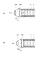
- FIG. 2A is a cross-sectional view showing a state before the distal end portion of the guide wire of the present embodiment is inserted into a living body lumen.
- FIG. 2B is a cross-sectional view showing a state in which the distal end portion of the guide wire of the present embodiment is inserted into the living body lumen and in contact with the wall surface in the living body lumen.
- the tip unit 7 is represented as a perspective view for convenience of explanation.
- a guide wire travels in a bent blood vessel or penetrates (penetrates) a lesion. At this time, the distal end portion of the guide wire may be pressed against the wall surface in the living body lumen. When the distal end of the guide wire is pressed against the wall surface of the living body lumen, the frictional resistance between the guide wire and the wall surface of the living body lumen increases, and the operability of the guide wire may be reduced.
- the guide wire may have a distal end hooked on the stent strut or enter a gap between the wall surface of the living body lumen and the stent strut, thereby causing the guidewire to be removed. There is a risk that the operability of the Furthermore, if the guide wire is pushed while the distal end of the guide wire is hooked, the guide wire may be bent at the distal end. Movement of the distal end of the guidewire that occurs when this deflection is resolved can damage the wall within the biological lumen.
- the guide wire 1 includes the distal end unit 7 provided at the distal end portion of the coil 4.
- the distal end of the coil 4 extends substantially straight before being inserted into the living body lumen.
- the distal end portion of the coil 4 may be pressed against the wall surface 55 in the living body lumen when advancing inside the living body lumen.
- a part of the tip rotating body 71 protrudes or is exposed outward from the surface of the coil 4 or the support portion 72. Then, as indicated by an arrow A1 shown in FIG. 2B, the distal-end rotating body 71 contacts a portion (for example, a wall surface or a narrowed portion) in the living body lumen and rotates when receiving an external force.
- a portion for example, a wall surface or a narrowed portion
- the tip rotation body 71 is rotated by contact with the wall surface 55 in the living body lumen and receiving an external force, even if magnetic or electric power is not supplied.
- the guide wire 1 according to the present embodiment can reduce the frictional resistance between the coil 4 or the tip unit 7 and the wall surface 55 in the living body lumen with a simple structure.
- tip part of the guide wire 1 reduces the guide wire 1 which concerns on this embodiment.
- the distal end portion of the guide wire 1 is less likely to be caught in the narrowed portion 56 including the calcified lesion 57, and the decrease in operability of the guide wire 1 and the occurrence of bending can be suppressed.
- the distal end portion of the guide wire 1 is not easily caught by the strut 58 of the stent, and the operability of the guide wire 1 is improved. It is possible to suppress the occurrence of deterioration or deflection.
- the tip unit 7 is preferably provided in a portion (region) including at least the tip of the guide wire 1 as shown in FIGS. 1 to 2B. More preferably, the distal end rotating body 71 is provided at least at the distal end of the guide wire 1. As shown in FIG. 2 (b), the distal end of the guide wire 1 is first placed on a portion in the living body lumen (the wall 55 in FIG. 2 (b)) when the guide wire 1 advances in the living body lumen. There is a high possibility of touching. In addition, since the tip of the guide wire 1 is a portion to which a load is most applied during the operation of the guide wire, the frictional resistance tends to increase.
- the rotating body at the tip of the guide wire 1 (the rotating body includes the tip rotating body 71), the frictional resistance between the surface of the tip of the guide wire 1 and the portion of the biological lumen is reduced. The deterioration of the operability of the guide wire 1 is further suppressed. In particular, by reducing the frictional resistance at the tip of the guide wire 1, the guide wire 1 can effectively suppress the tip from entering the gap between the wall surface 55 in the living body lumen and the stent.
- FIG. 5 is a perspective view showing the tip unit of the present embodiment.
- FIG. 6 is a perspective view showing the support portion of the present embodiment.
- FIG. 7 is a perspective view for explaining a modified example of the method of fixing the support portion of the present embodiment.
- FIG. 8 is a perspective view illustrating a first method of manufacturing the tip unit of the present embodiment.
- FIG. 9 is a perspective view illustrating a second method of manufacturing the tip unit of the present embodiment.
- the tip unit 7 of the present embodiment includes a tip rotation body 71 and a support portion 72.
- the tip rotation body 71 is a sphere or a spheroid.
- FIGS. 5 to 14 (b) and FIGS. 18 to 26 the case where the tip rotating body is a sphere is taken as an example.
- FIG. 15 to FIG. 17C the case where the tip rotating body is a spheroid is taken as an example.
- the constituent material of the tip rotating body 71 may be either a metal material or a resin material, and is more preferably a metal material.
- the metal material used for the tip rotating body 71 include the same materials as the materials listed as the constituent materials of the first wire 2 and the second wire 3. Among these, it is more preferable that a Ni—Ti based alloy or stainless steel be used as a constituent material of the tip rotating body 71.
- the constituent material of the tip rotating body 71 may be fluorine resin (PTFE, ETFE, etc.). In this case, the frictional resistance between the distal end of the guide wire 1 and the wall surface 55 in the living body lumen is further reduced.
- the tip rotation body 71 may be provided with a coating capable of reducing frictional resistance on the surface.
- the material of the coating may, for example, be a fluorine-based resin or a hydrophilic material that exhibits lubricity when wet.
- the tip rotation body 71 may reduce the frictional resistance between the surface of the tip rotation body 71 and the wall surface 55 in the living body lumen by providing a fine uneven shape on the surface.
- the size (diameter) of the tip rotating body 71 is not particularly limited, but is about 0.1 mm to 0.8 mm.
- the support portion 72 includes a pedestal bottom surface portion 721, a pedestal side surface portion 722, an opening portion 724, and a joint portion 726.
- the pedestal bottom portion 721 receives the tip rotating body 71 on the surface (main surface).
- the shape of the pedestal bottom portion 721 is preferably circular as shown in FIG.
- the shape of the pedestal bottom portion 721 is not limited to a circle, and may be, for example, a polygon such as a triangle, a square, or a pentagon.
- the pedestal side surface portion 722 corresponds to the side surface (outer surface) of the column having the pedestal bottom surface portion 721 as a bottom surface.
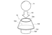
- the pedestal side surface portion 722 is connected to the edge (specifically, the outer peripheral edge portion) of the pedestal bottom surface portion 721, covers the periphery of the tip rotating body 71, and accommodates a part of the tip rotating body 71 together with the pedestal bottom portion 721. . That is, at least a part of the tip rotation body 71 is accommodated in a space 725 formed between the pedestal side surface portion 722 and the pedestal bottom surface portion 721.
- the pedestal side surface portion 722 has a tapered shape whose outer diameter decreases toward the distal end side of the support portion 72.
- the pedestal side surface portion 722 is a part of a pyramid whose bottom surface is the pedestal bottom surface portion 721. As shown in FIGS. 5 and 6, when the pedestal bottom portion 721 is circular, the pedestal side portion 722 is a part of a conical shape.
- the pedestal side surface portion 722 is not limited to a part of a conical shape, and may be a columnar shape, a barrel shape in which the middle part is curved outward, or a wound type in which the middle part is curved inward. Good.
- the opening 724 is provided on the distal end side of the support 72.
- the opening 724 corresponds to the bottom surface of the cylindrical body having the pedestal bottom surface portion 721 as the bottom surface on the opposite side to the pedestal bottom surface portion 721.
- the opening 724 is circular.
- the opening 724 causes a portion of the tip rotation body 71 accommodated in the space 725 to protrude outward from the surface of the support 72.
- the amount L1 of protrusion of the tip end rotating body 71 protruding from the opening 724 is not particularly limited, and in the volume ratio or diameter ratio (long axis ratio or short axis ratio when the tip rotating body 71 is a spheroid) It is 1% or more and less than 50%, more preferably 20% or more and 30% or less.
- the guide wire 1 has a high probability that the tip rotation body 71 contacts the wall surface 55 in the living body lumen.
- the gap L2 between them it is about 0.002 mm or more and 0.010 mm or less on one side.
- the joint 726 is a portion fixed to the coil 4 and the first wire 2.
- the joint portion 726 extends from the pedestal bottom portion 721 toward the proximal end side of the guide wire 1.
- the shape of the joint 726 is a cylinder or a cylinder.
- the outer diameter of the joint portion 726 is equal to or less than the inner diameter of the coil 4, and is inserted into the inside of the coil 4 from the tip end side of the coil 4.
- the outer peripheral surface of the joint portion 726 is fixed to the inner peripheral surface of the coil 4.
- the bonding portion 726 When the bonding portion 726 has a cylindrical shape, the bonding portion 726 is fixed to the distal end portion of the first wire 2 at the pedestal bottom surface portion 721.
- the joint portion 726 and the coil 4 and the first wire 2 are fixed by solder (brazing material) or an adhesive.
- the inner diameter of the bonding portion 726H is equal to or larger than the outer diameter of the coil 4 and It is also good.
- the bonding portion 726H extends from the pedestal bottom surface portion 721 toward the base end side, and is disposed to cover the outer peripheral surface of the distal end side of the coil 4 as shown by arrow A2 shown in FIG. 7A.
- the inner circumferential surface of the joint portion 726H is fixed to the outer circumferential surface of the coil 4 by a solder (brazing agent), an adhesive or the like.
- the tip unit 7 can be manufactured by pushing the tip rotating body 71 from the opening 724 into the space 725 between the pedestal side surface portion 722 and the pedestal bottom portion 721 as indicated by an arrow A3 shown in FIG.
- the tip unit 7 mounts the pedestal bottom portion 721 after pushing the tip rotating body 71 into the pedestal side surface portion 722 provided as a separate member from the pedestal bottom portion 721. It may be manufactured by bonding to the edge of the side surface portion 722.
- the tip rotation body 71 is supported by the support portion 72, the tip rotation body 71 is stably disposed, and the drop of the tip rotation body 71 is suppressed. Further, the tip rotation body 71 is supported by the support portion 72 and is easy to rotate. Furthermore, the support portion 72 that supports the tip rotation body 71 is fixed to the wire main body 10 (specifically, the first wire 2) and the coil 4. Therefore, the guide wire 1 ensures torque transmission.
- the pedestal side surface portion 722 has a tapered shape whose outer shape decreases toward the tip end side of the support portion 72. Therefore, the distal end portion of the guide wire 1 can be easily inserted into a thin living body lumen.
- the opening 724 is circular. When the opening 724 is circular, the tip rotation body 71 can apply a sphere having a larger diameter.
- the tip rotation body 71 Since the protrusion amount L1 of the tip rotation body 71 which protrudes from the opening part 724 can be enlarged as the tip rotation body 71 is a spherical body, the tip rotation body 71 becomes easy to contact the wall surface 55 in a biological lumen. Thereby, the frictional resistance between the guide wire 1 and the wall surface 55 in the living body lumen can be more reliably reduced.
- the support portion 72 can stably support the tip rotating body 71. Further, since the joint portion 726 is fixed to the coil 4 and the wire main body 10, torque transmission of the guide wire 1 is secured. Furthermore, when the bonding portion 726 is fixed to the inner peripheral surface of the coil 4, the outer shape of the support portion 72 becomes larger than the outer shape of the coil, or a step is generated between the support portion 72 and the coil 4. Therefore, the decrease in operability of the guide wire 1 is suppressed.
- a drug, a lubricant, or the like may be filled in a space 725 between the pedestal side surface portion 722 and the pedestal bottom surface portion 721.
- FIG. 10 is a perspective view showing a first modified example of the tip unit of the present embodiment.
- the tip unit 7A of this modification includes a tip rotating body 71 and a support 72A.
- the support portion 72A has a pedestal ring portion 727 provided in a space 725 between the pedestal side surface portion 722 and the pedestal bottom surface portion 721.
- the tip unit 7A of this modification is different from the tip unit 7 described above with reference to FIGS.
- the pedestal ring portion 727 is fixed to the inner peripheral surface of the pedestal side surface portion 722. Accordingly, the pedestal ring portion 727 receives the outer peripheral portion (outer surface) of the distal end rotating body 71 on the distal end side with respect to the pedestal bottom surface portion 721.
- the pedestal ring portion 727 receives the distal-end rotating body 71 on the distal end side relative to the pedestal bottom surface portion 721, the distal-end rotating body 71 can be stably supported. Further, compared to the case where the pedestal ring portion 727 is not provided, the axial length of the pedestal side surface portion 722 (the axial length from the pedestal bottom surface portion 721 to the opening 724) can be increased. As a result, the tapered shape of the pedestal side surface portion 722 can be made longer, and therefore, the guide wire can be easily inserted into a thin living body lumen and penetrated into a lesion such as a narrowed portion or an obstructed portion.
- the pedestal ring portion 727 receives the distal-end rotating body 71 at the distal end side relative to the pedestal bottom surface portion 721, so that a gap is formed between the distal-end rotating body 71 and the pedestal bottom surface portion 721. Becomes possible. Therefore, the accommodation space of the tip rotation body 71 (the space 725 between the pedestal bottom surface portion 721 and the pedestal side surface portion 722) can be made wider. Thereby, the accommodation space of tip rotation object 71 can hold a large amount of medicines and lubricants.
- FIG. 11 to 14 are views showing second to fifth modified examples of the tip unit of the present embodiment.
- FIG. 11B is a cross-sectional view taken along the cross section C1-C1 shown in FIG.
- FIG. 12 (b) is a cross-sectional view taken along the section plane C2-C2 shown in FIG. 12 (a).
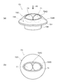
- FIG. 13 (b) is a plan view as viewed in the direction of arrow A 5 shown in FIG. 13 (a).
- FIG. 14 (b) is a plan view as viewed in the direction of arrow A 6 shown in FIG. 14 (a).
- the distal end rotating body 71 may be provided at a portion other than the distal end of the distal end units 7B and 7C.
- the tip end rotating body 71 may be provided on the pedestal side surface portions 722B and 722C.
- the tip rotating body 71 may not be provided at the tip of the tip unit 7B. Even when the rotating body is provided at a portion other than the tip of the tip unit, the tip unit is provided at the tip of the outer layer portion (in the present embodiment, the coil 4), and the rotating body is positioned at the tip of the outer layer portion. As long as it does, the rotary body corresponds to the "tip rotary body".
- the tip units 7B and 7C shown in FIGS. 11 (a) to 12 (b) have a plurality of tip rotators 71.
- the pedestal side surface portions 722 B and 722 C have a number of openings 724 corresponding to the number of tip rotating bodies 71.
- the openings 724 of the pedestal side surface portions 722B and 722C are disposed at different positions in the circumferential direction of the guide wire 1, respectively.
- a part of the tip rotation body 71 protrudes outward from the surface of the support portions 72B and 72C through the opening 724.
- the plurality of tip end rotating bodies 71 project from the pedestal side surface portions 722B and 722C of the support portions 72B and 72C. Therefore, even when the distal end portion of the guide wire 1 is bent in various directions, the distal end rotating body 71 can contact and rotate the wall surface 55 in the living body lumen. Thereby, even when the distal end of the guide wire 1 is bent in various directions, the frictional resistance between the distal end of the guide wire 1 and the wall surface 55 in the living body lumen can be reduced.
- the sizes of the plurality of tip rotating bodies 71 may be the same as or different from each other.
- a relatively large tip rotating body 71 is disposed in the central portion of the space 725 and relatively small. It becomes possible to arrange the tip rotation body 71 around the relatively large tip rotation body 71.
- a part of the plurality of tip rotating bodies 71 may protrude from one opening.
- the tip unit 7D shown in FIGS. 13 (a) and 13 (b) has two tip rotating bodies 71 and a support 72D.
- the pedestal bottom portion 721 of the support portion 72D has a circular shape.
- the pedestal side surface portion 722D of the support portion 72D has an elliptical opening 724D provided at the tip. At this time, the pedestal side surface portion 722D is smoothly formed from the circular pedestal bottom portion 721 toward the elliptical opening 724D.
- a part of the two tip rotating bodies 71 protrudes outward from the surface of the support 72D through the oval shaped opening 724D.
- the tip unit 7E shown in FIGS. 14 (a) and 14 (b) has three tip rotation bodies 71 and a support 72E.
- the pedestal bottom portion 721 of the support portion 72E has a circular shape.
- the pedestal side surface portion 722E of the support portion 72E has an opening 724 provided at the tip.
- the shape of the opening 724 may be circular or elliptical. Parts of the three tip rotating bodies 71 protrude outward from the surface of the support 72E through the openings 724.
- FIG. 15 is a cross-sectional view showing a guide wire according to a modification of the present embodiment.
- FIG. 16 is a perspective view showing the tip unit of this modification.
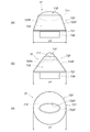
- FIG. 17 is a plan view showing the tip unit of this modification.
- FIG. 17A is a plan view when viewed from a direction orthogonal to the axis 11 of the wire main body 10 and the long axis 711 of the tip rotating body 71F.
- FIG. 17B is a plan view when viewed from the direction parallel to the long axis 711 of the tip rotation body 71F.
- FIG. 17C is a plan view when viewed from the tip side along the axis 11 of the wire main body 10.
- the first wire 2A has a first diameter constant portion 21, a second diameter constant portion 23, a first taper portion 22, and a flat portion 26. That is, compared to the first wire 2 described above with reference to FIG. 1, the first wire 2A of the guide wire 1A according to the present modification further includes the flat plate portion 26.
- the flat plate portion 26 is provided on the tip end side of the second constant diameter portion 23.
- the first diameter constant portion 21, the first taper portion 22, the second diameter constant portion 23, and the flat portion 26 are disposed in this order from the proximal end side to the distal end side of the first wire 2A. That is, the flat plate portion 26 is disposed closer to the tip than the second constant diameter portion 23 and is connected to the second constant diameter portion 23.
- the flat plate portion 26 has a flat plate shape (ribbon shape), and may be used after being deformed into a desired shape. That is, the operator may bend the tip of the guide wire into a desired shape in advance in order to increase the blood vessel selectivity of the guide wire at the bifurcation of the blood vessel. Thus, bending the distal end portion of the guide wire into a desired shape is called reshaping or preforming or the like. In the specification of the present application, the direction in which the distal end portion of the guide wire is curved by the reshape is referred to as the “reshape direction”.
- the reshaping direction of the guide wire 1A is a direction perpendicular to the main surface of the flat plate portion 26. That is, the reshaping direction is the direction perpendicular to the longitudinal section when the guide wire 1A is cut along a plane (longitudinal section of the guide wire shown in FIG. 15) including the axis 11 of the wire main body 10 (in FIG. In the depth direction).
- the guide wire 1A includes a tip unit 7F provided at the tip of the coil 4.
- the tip unit 7F is fixed to the coil 4 and the first wire 2A (specifically, the flat plate portion 26) by a solder (brazing material), an adhesive, or the like.
- the tip unit 7F of the present modification includes a tip rotation body 71F and a support portion 72F.
- the guide wire 1A according to the present modification is an example in which the "rotating body" of the present invention includes a "tip rotating body”.
- the tip rotation body 71F is a spheroid.
- the pedestal bottom surface portion 721 of the support portion 72F of this modification has a circular shape.
- the length L3 (diameter of the pedestal bottom portion 721) shown in FIG. 17 (a) is the length L4 (diameter of the pedestal bottom portion 721) shown in FIG. 17 (b) and FIG. It is the same as the length L5 (diameter of the pedestal bottom portion 721).
- the pedestal side surface portion 722F of the support portion 72F has an elliptically shaped opening 724F provided at the tip and along the shape of the tip rotation body 71F. At this time, the pedestal side surface portion 722F is smoothly formed from the circular pedestal bottom portion 721 toward the elliptical opening 724F.
- the support portion 72F has a pedestal ring portion 727F provided in a space 725 between the pedestal side surface portion 722F and the pedestal bottom surface portion 721.
- the pedestal ring portion 727F is fixed to the inner peripheral surface of the pedestal side surface portion 722F. Accordingly, the pedestal ring portion 727F receives the outer peripheral portion (outer surface) of the distal end rotating body 71F on the distal end side of the pedestal bottom surface portion 721.
- the tip rotating body 71F has anisotropy in the rotation direction.
- the major axis 711 of the distal end rotator 71F extends in a direction (radial direction) orthogonal to the axis 11, and the major axis 711 of the distal end rotator 71F is parallel to the main surface of the flat plate portion 26. That is, the long axis 711 of the tip rotation body 71F is included in a plane (longitudinal section of the guide wire shown in FIG. 15) including the axis 11 of the wire main body 10 of the guide wire 1A.
- the guide wire 1A can reduce the frictional resistance between the tip of the guide wire 1A and the wall surface 55 in the living body lumen, and can control the moving direction of the tip of the guide wire 1A in an arbitrary direction. Thereby, the guide wire 1A improves blood vessel selectivity.
- the major axis 711 of the tip rotation body 71F extends in a direction (radial direction) orthogonal to the axis 11, and is parallel to the main surface of the flat plate portion 26. Therefore, when the surgeon reshapes the distal end portion of the guide wire 1A, the reshaping direction and the long axis 711 of the distal end rotating body 71F can be orthogonal to each other. Thereby, the guide wire 1A further improves blood vessel selectivity.
- the reshaping direction and the major axis 711 of the tip rotating body 71F may be arranged in parallel with each other.
- the opening 724F provided at the tip of the support 72F has an elliptical shape along the shape of the tip rotating body 71F.
- the opening 724F can prevent the tip rotating body 71F from falling off and control the rotation direction of the tip rotating body 71F.
- the support portion 72F has a pedestal ring portion 727F provided in the space 725 between the pedestal side surface portion 722F and the pedestal bottom surface portion 721. Since the pedestal ring portion 727F receives the tip rotating body 71F at the tip side of the pedestal bottom portion 721, the tip ring rotating portion 71F can be stably supported. Further, the axial length of the pedestal side surface portion 722F (the axial length from the pedestal bottom surface portion 721 to the opening 724F) can be increased as compared with the case where the pedestal ring portion 727F is not provided.
- the tapered shape of the pedestal side surface portion 722F can be lengthened, and therefore, the guide wire 1A can be easily inserted into a thin living body lumen and penetrated into a lesion such as a narrowed portion or an obstructed portion. .
- the support portion 72F may not have the pedestal ring portion 727F.
- the tip rotation body 71F receives the outer peripheral portion (outer surface) of the tip rotation body 71F at the pedestal bottom surface portion 721.
- the tip rotating body may be a sphere as described above with reference to FIG.
- the tip end rotator is a sphere
- the tip end rotator 71 (see FIG. 5) can rotate uniformly over the entire circumferential direction (360 ° direction).
- the tip rotating body 71 rotates stably, and the tip portion of the guide wire 1A and the wall surface 55 in the living body lumen The friction resistance between them can be reduced.
- FIG. 18 is a cross-sectional view showing a first modified example of the support portion of the present embodiment.
- the coil 4 is represented as a cross-sectional view
- the support portion 72G is represented as a perspective view.
- the support portion 72G of this modification is a cylindrical member.
- a circular opening 724G is provided on the tip end side of the support portion 72G.
- a bottom surface portion 721G is provided on the base end side of the support portion 72G.
- the bottom surface portion 721G of the support portion 72G has a circular shape.
- Inside the support portion 72G a space 725G extending from the opening 724G to the bottom surface portion 721G is formed.
- the diameter of the space 725G as viewed along the axis 11 may be the same along the axis 11 or may decrease from the distal end to the proximal end.
- the support portion 72G of the present modification has a cylindrical shape in which the distal end side portion is opened as the opening portion 724G and the proximal end side portion is closed as the bottom surface portion 721G.
- the support portion 72G is fixed to the coil 4 and the first wire 2A inside the coil 4 by a solder (brazing material), an adhesive, or the like. Specifically, the support portion 72G is fixed to the inner circumferential surface of the coil 4 and the flat plate portion 26 of the first wire 2A. The flat plate portion 26 of the first wire 2A is fixed to the bottom surface portion 721G of the support portion 72G with an adhesive in a state where the tip end portion is inserted into the bottom surface portion 721G of the support portion 72G. The support portion 72G receives and supports the outer peripheral portion of the tip rotation body 71 at the edge of the opening 724G.
- the outer diameter and the inner diameter of the distal end portion of the coil 4 provided with the distal end rotating body 71 are reduced toward the distal end side.
- the tip rotating body 71 is provided between the tip of the coil 4 whose outer diameter and inner diameter are reduced and the support portion 72G. A part of the tip rotating body 71 protrudes outward from the surface of the coil 4. The other part of the tip rotating body 71 is accommodated inside the coil 4.
- the coil 4 may be reduced only in the inner diameter, and the outer diameter may not be reduced.
- the support portion 72 ⁇ / b> G can have a simple structure in which the cylindrical member is fixed to the inner peripheral surface of the coil 4.
- the support portion 72G is fixed to the wire main body 10 (specifically, the flat plate portion 26 of the first wire 2A), torque transmission of the guide wire 1A is secured.
- FIG. 19 is a cross-sectional view showing a second modified example of the support portion of the present embodiment.
- FIG. 20 is a cross-sectional view showing a third modified example of the support portion of the present embodiment.
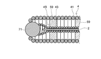
- the support portions 4A and 4B shown in FIG. 19 and FIG. 20 are coils formed by winding the wire 43 in a spiral shape.
- the support portions 4A and 4B shown in FIGS. 19 and 20 are examples of the “second coil” in the present invention.
- the coil 4 disposed on the outer periphery of the distal end portion of the wire main body 10 shown in FIGS. 19 and 20 and covering the distal end portion of the wire main body 10 is an example of the “first coil” in the present invention.
- the support portions 4A and 4B cover at least a part of the wire main body 10 (specifically, the first wire 2), and the inner peripheral surface of the coil 4 and the fixing material 59 such as solder (brazing material) and adhesive. It is fixed to both sides of the wire body 10.
- the support portions 4A and 4B may be fixed to the wire main body 10 or may be fixed to the coil 4. That is, the support portions 4A and 4B are fixed to at least one of the coil 4 and the wire main body 10.
- the support portions 4A and 4B are fixed to the inner peripheral surface of the coil 4 and the wire main body 10 at two points by the fixing material 59.
- the tip portions of the support portions 4A and 4B are fixed to both the inner circumferential surface of the coil 4 and the wire main body 10 in the vicinity of the tip rotation body 71.
- the proximal ends of the support portions 4A and 4B are fixed to both the inner circumferential surface of the coil 4 and the wire body 10 at the proximal ends of the support portions 4A and 4B.
- the fixed location and fixed number of support part 4A, 4B with respect to the coil 4 and the wire main body 10 are not limited to this.
- the support 4A receives the tip rotation body 71 at the tip.
- the support portion 4B receives the tip rotation body 71 at the tip portion (a portion where the outer diameter is enlarged). As shown in FIG. 20, the outer diameter of the tip end portion of the support portion 4B may be increased toward the tip end side.
- the outer diameter and the inner diameter of the distal end portion of the coil 4 provided with the distal end rotating body 71 decrease toward the distal end side.
- the tip rotation body 71 is provided between the tip of the coil 4 whose outer diameter and inner diameter are reduced and the tip of the support portions 4A and 4B. A part of the tip rotating body 71 protrudes outward from the surface of the coil 4. The other part of the tip rotating body 71 is accommodated inside the coil 4.
- the tip of the wire main body 10 is separated from the tip rotation body 71.
- the support portions 4A and 4B are formed by winding the strands 43 in a spiral shape.
- Coil second coil
- the distal end rotating body 71 is supported by the distal end portions of the support portions 4A and 4B. Since the support portions 4A and 4B, which are coils, are flexible and elastic, the tip rotation body 71 is the shaft of the guide wire 1 according to the amount of pressing of the tip rotation body 71 supported by the tip portions of the support portions 4A and 4B. It becomes movable in 11 directions. Therefore, the distal end portion of the guide wire 1 is excellent in flexibility.
- the guide wire 1 is excellent in torque transmission. Since the fixing material 59 is provided in the vicinity of the tip rotation body 71, the support portions 4A and 4B are fixed in the vicinity of the tip of the wire main body 10. Therefore, the torque transferability of the guide wire 1 is secured. Furthermore, since the tip of the wire main body 10 is separated from the tip rotating body 71, the tip rotating body 71 can be smoothly rotated. As shown in FIG. 20, when the outer diameter of the tip end portion of the support portion 4B is enlarged toward the tip end side, the support portion 4B can support the tip rotation body 71 more stably.
- FIG. 21 is a cross-sectional view showing a guide wire according to a second embodiment of the present invention.
- FIG. 22 is an example of a cross-sectional view taken along the section plane C3-C3 shown in FIG.
- the guide wire 1B according to the present embodiment includes the wire main body 10, a covering portion (outer layer portion) 4C that covers the tip end portion of the wire main body 10, a tip rotating body 71, and a side rotating body 73. That is, the guide wire 1B according to the present embodiment is an example in which the "rotating body” of the present invention includes the “tip rotating body” and the “lateral rotating body”. The “covering portion” in the present embodiment is an example of the "outer layer portion” in the present invention.
- the wire body 10 is as described above with respect to FIG. However, the shape of the wire main body 10 of the guide wire 1B according to the present embodiment may not necessarily be the same as the shape of the wire main body 10 described above with reference to FIG.
- the cover 4C is formed of a resin material.
- a resin material for forming the covering portion 4C polyolefins such as polyethylene and polypropylene, polyvinyl chloride, polyester (PET, PBT etc.), polyamide, polyimide, polyurethane, polystyrene, silicone resin, polyurethane elastomer, polyester elastomer, polyamide elastomer, etc. And various rubber materials such as latex rubber and silicone rubber, or composite materials such as polymer alloys or polymer blends in which two or more of them are combined.
- the cover 4C may have a structure (laminated structure) in which a plurality of layers are stacked. It is preferable that the covering portion 4C is flexible to such an extent that the bending of the wire main body 10 is not hindered, and the outer surface is a smooth surface without unevenness.
- coated parts contains the radiopaque substance.
- the radiopaque substance include elemental metals or alloys such as tungsten, barium sulfate, bismuth, gold, platinum and the like, and fine particles made of a compound.
- the particle size of the radiopaque substance is preferably 1 to 4 ⁇ m.
- the content of the X-ray opaque material in the synthetic resin is 70% by weight or more, and preferably 70 to 85% by weight. More preferably, it is 75 to 85% by weight.
- the surface of the covering portion 4C be coated with a hydrophilic material.
- the hydrophilic material of the covering portion 4C include the hydrophilic material of the resin coating layer 8 described above with reference to FIG.
- the tip rotation body 71 and the side rotation body 73 are provided at the tip portion of the covering portion 4C.
- the tip rotating body 71 is provided at the tip of the covering portion 4C.
- the side rotation body 73 is provided on the side (outer periphery) of the covering portion 4C.
- the tip rotation body 71 and the side rotation body 73 are rotatably fitted in a hole 41C formed at the tip of the covering 4C.
- the constituent material of the tip rotating body 71 is as described above with reference to FIG.
- the constituent material of the side rotary body 73 is the same as the constituent material of the tip rotary body 71.
- the side rotation body 73 is a sphere or a spheroid.
- each of the tip rotation body 71 and the side rotation body 73 of the guide wire 1B shown to FIG. 21 and FIG. 22 is a spherical body.
- the range in which the side rotating body 73 is provided is preferably about 25 cm from the tip of the guide wire 1B to the base end, and more preferably about 1 cm from the tip of the guide wire 1B to the base end.
- the number of the side rotating bodies 73 provided on the outer peripheral portion of the covering portion 4C is not particularly limited, as shown in FIG. There may be four, or three or less, or five or more.
- a part of the distal end rotating body 71 and the side rotating body 73 is protruded or exposed outward from the surface of the covering portion 4C. Then, the distal end rotating body 71 and the side rotating body 73 contact with a portion (for example, a wall surface or a narrowed portion) in the living body lumen and rotate when receiving an external force. Thereby, in the guide wire 1B according to the present embodiment, the frictional resistance between the tip and the side surface of the covering portion 4C and the portion of the living body lumen is reduced, and the operability of the guide wire 1B is lowered. It is suppressed.
- the tip rotation body 71 and the side rotation body 73 are rotated by contact with the wall surface 55 in the living body lumen and receiving an external force, even if magnetic or electric power is not supplied.
- the guide wire 1B which concerns on this embodiment can reduce the frictional resistance between the coating
- tip part of the guide wire 1B reduces the guide wire 1B which concerns on this embodiment.
- the distal end portion of the guide wire 1B is less likely to be caught on the narrowed portion or the stent in the biological lumen, and the guide wire 1B can suppress the decrease in operability of the guide wire 1B and the occurrence of bending.
- the side rotation body 73 is provided in a range of about 1 cm from the tip end of the guide wire 1B to the proximal end side in the covering portion 4C.
- the region from the distal end to the proximal end of the guide wire 1B is in contact with the blood vessel wall when the operator reshapes the distal end of the guide wire 1B into a curved shape to improve blood vessel selectivity. It is a part that is likely to Therefore, when the operator deforms the distal end portion of the guide wire 1B into a curved shape, the guide wire 1B according to the present embodiment is a frictional resistance between the surface of the covering portion 4C and the portion of the living body lumen. As a result, the operability of the guide wire 1B is reduced.
- FIG. 23 is a plan view showing a guide wire according to a third embodiment of the present invention.
- FIG. 24 is an enlarged view of the area A11 shown in FIG.
- FIG. 25 is a plan view as viewed in the direction of arrow A9 shown in FIG.
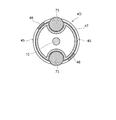
- FIG. 26 is a cross sectional view taken along the cross section C4-C4 shown in FIG.
- the guide wire 1C according to the present embodiment includes a wire main body 10, a tubular member (outer layer portion) 4D, a distal end rotating body 71, a side rotating body 73, and a support film 47. That is, the guide wire 1C according to the present embodiment is an example in which the "rotating body” of the present invention includes the “tip rotating body” and the “lateral rotating body”.
- the “cylindrical member” in the present embodiment is an example of the “outer layer portion” in the present invention.
- the tip of the cylindrical member 4D is fixed to the tip of the wire main body 10 by a fixing material 51 such as solder (brazing material) or an adhesive.
- the base end of the cylindrical member 4D is fixed in the middle of the wire main body 10 by a fixing material 53 such as a solder (brazing material) or an adhesive.
- a fixing material 53 such as a solder (brazing material) or an adhesive.
- the shape and constituent materials of the wire body 10 are as described above with reference to FIG.
- the shape of the wire main body 10 of the guide wire 1C according to the present embodiment may not necessarily be the same as the shape of the wire main body 10 described above with reference to FIGS.
- the cylindrical member 4D is manufactured, for example, by processing a metal pipe or the like.
- a metal used for forming the tubular member 4D a biocompatible metal is preferable.
- stainless steel, tantalum or tantalum alloy, platinum or platinum alloy, cobalt such as gold or gold alloy, cobalt chromium alloy, etc. Base alloys, nickel titanium alloys and the like can be mentioned.
- the tip of the first wire 2 is inserted into the internal space of the cylindrical member 4D.
- the slit 45 which connects the internal space of cylindrical member 4D and the external space of cylindrical member 4D is formed in the outer peripheral part of cylindrical member 4D.
- adjacent tubular members 4D are connected by the link portion 46 via the slits 45.
- cylindrical member 4D can have pliability and blood vessel followability is secured.
- the number of link portions 46 when viewed in the circumferential direction of the cylindrical member 4D is not limited to two, and may be three or more.
- the tip rotation body 71 and the side rotation body 73 are provided at the tip portion of the cylindrical member 4D.
- the tip rotation body 71 is provided at the tip of the cylindrical member 4D in a state where a part thereof protrudes outward from the surface of the support portion 72.
- the side rotating body 73 is rotatably provided in a state of being sandwiched between the support film 47 and the cylindrical member 4D. As shown in FIGS. 24 and 26, a part of the side rotation body 73 protrudes to the outside of the cylindrical member 4D through the slit 45 of the cylindrical member 4D. That is, the side rotation body 73 is provided in the portion of the slit 45.
- the constituent material of the tip rotating body 71 is as described above with reference to FIG.
- the constituent material of the side rotary body 73 is the same as the constituent material of the tip rotary body 71.
- the side rotation body 73 is a sphere or a spheroid. Note that each of the tip rotation body 71 and the side rotation body 73 of the guide wire 1C shown in FIG. 23 is a sphere.
- the range in which the side rotary body 73 is provided is preferably about 25 cm from the tip of the guide wire 1C to the base end, and more preferably about 1 cm from the tip of the guide wire 1C to the base end.
- the installation position of the side rotation body 73 is not limited to the example shown in FIG. 23 and may be provided from the distal end to the proximal end of the cylindrical member 4D.
- the side rotation body 73 is provided continuously along the axis 11 of the wire main body 10 in the portion of the slit 45.
- the installation position of the side rotation body 73 is not limited to the example shown in FIG.
- the slits 45 may be provided in the portion of the slit 45 at intervals along the axis 11 of the wire main body 10.
- the slits 45 provided with the side rotation bodies 73 and the slits 45 not provided with the side rotation bodies 73 are alternately arranged.
- the flexibility of the portion of the guide wire 1C provided with the cylindrical member 4D is further enhanced as compared to the case where the side rotation body 73 is provided continuously to the portion of the slit 45. .
- the side rotary bodies 73 adjacent to each other in the axial direction of the guide wire 1C are provided at the same position in the circumferential direction of the cylindrical member 4D.
- the installation position of the side rotary body 73 adjacent to the axial direction of the guide wire 1C is not limited to the example shown in FIG. 23, and may be provided at different positions in the circumferential direction of the cylindrical member 4D. .
- the tip rotation body 71 is provided at the tip (the portion of the fixing material 51) of the guide wire 1C using, for example, the support portion 72 described above with reference to FIGS. That is, in the guide wire 1C shown in FIG. 23, the tip unit 7 is fixed to the tip of the cylindrical member 4D and the wire main body 10 by the fixing material 51 such as solder (brazing material) or adhesive. Details of the tip unit 7 are as described above with reference to FIGS. 5 and 6.
- the support film 47 is, for example, a cylindrical body such as a tube, and is fixed inside the cylindrical member 4D.
- the support film 47 receives and supports the side rotation body 73 while the side rotation body 73 is rotatable.
- Examples of the material of the support film 47 include various urethane rubber materials such as polyurethane and polyurethane elastomer, and also include composite materials such as a polymer alloy or a polymer blend in which a plurality of rubber materials are combined.
- the width L6 of the slit 45 in the direction of the axis 11 is smaller than the diameter D1 of the side rotation body 73. Therefore, it is suppressed that the side rotation body 73 falls outside the cylindrical member 4D through the slit 45.
- an arc portion 48 formed as a part of a circumference is provided inside the slit 45.
- the arc portion 48 has an inner diameter D2 smaller than the diameter D1 of the side rotation body 73, and holds the side rotation body 73. That is, the side rotation body 73 is disposed at the position of the arc portion 48 of the slit 45, and the arc portion 48 suppresses movement in the direction of the axis 11 and the circumferential direction of the cylindrical member 4D.
- a part of the tip rotating body 71 and the side rotating body 73 protrudes or is exposed outward from the surface of the cylindrical member 4D. Then, the distal end rotating body 71 and the side rotating body 73 contact with a portion (for example, a wall surface or a narrowed portion) in the living body lumen and rotate when receiving an external force. Thereby, in the guide wire 1C according to the present embodiment, the frictional resistance between the tip and the side surface of the cylindrical member 4D and the portion of the living body lumen is reduced, and the operability of the guide wire 1C is lowered. Is reduced.
- tip rotation body 71 and the side rotation body 73 are rotated by contact with the wall surface 55 in the living body lumen and receiving an external force, even if magnetic or electric power is not supplied.
- 1 C of guide wires concerning this embodiment can reduce the frictional resistance between cylindrical member 4D and the wall surface 55 in a living body lumen by simple structure.
- tip part of the guide wire 1C reduces 1 C of guide wires which concern on this embodiment.
- the distal end portion of the guide wire 1C is less likely to be caught by the narrowing portion or the stent in the living body lumen, and the guide wire 1C can suppress the decrease in operability of the guide wire 1C and the occurrence of bending.
- the side rotation body 73 is provided in a range of about 1 cm from the tip end of the guide wire 1C to the base end side in the cylindrical member 4D.
- the region from the distal end of the guide wire 1C to the proximal end by about 1 cm contacts the blood vessel wall when the operator reshapes the distal end of the guide wire 1C to a curved shape to improve blood vessel selectivity. It is a part that is likely to Therefore, when the operator deforms the distal end portion of the guide wire 1C into a curved shape, the guide wire 1C according to the present embodiment is a friction between the lateral surface of the cylindrical member 4D and the portion of the living body lumen. The resistance is reduced, and the decrease in operability of the guide wire 1C is suppressed.
- 1, 1A, 1B, 1C guide wire
- 2, 2A first wire
- 3 second wire
- 4 coil
- 4A, 4B support portion
- 4C 4C Cover portion 4D: cylindrical member 6
- junction portion 7, 7A, 7B, 7C, 7D, 7E, 7F tip unit 8
- 9 resin coating layer
Landscapes
- Health & Medical Sciences (AREA)
- Life Sciences & Earth Sciences (AREA)
- Biophysics (AREA)
- Pulmonology (AREA)
- Engineering & Computer Science (AREA)
- Anesthesiology (AREA)
- Biomedical Technology (AREA)
- Heart & Thoracic Surgery (AREA)
- Hematology (AREA)
- Animal Behavior & Ethology (AREA)
- General Health & Medical Sciences (AREA)
- Public Health (AREA)
- Veterinary Medicine (AREA)
- Media Introduction/Drainage Providing Device (AREA)
Abstract
簡易的な構造によりガイドワイヤの表面と生体管腔内の部分との間の摩擦抵抗を低減できるガイドワイヤを提供する。ガイドワイヤ(1)は、長尺のワイヤ本体(10)と、ワイヤ本体(10)の先端部の外周に配置され先端部を覆う外層部(4)と、一部が外層部(4)の外側に向かって突出し生体管腔内の部分と接触し外力を受けると回転する回転体(71)と、を備える。
Description
本発明は、ガイドワイヤに関し、特に血管や胆管のような生体管腔内にカテーテルを導入する際に用いられるガイドワイヤに関する。
従来から、狭窄や閉塞が発症した血管等の治療のために、PCI(Percutaneous Coronary Intervention:経皮的冠状動脈インターベンション)という手技が実施されている。一般的なPCIでは、バルーンカテーテルやステントなどの医療デバイスを治療対象となる狭窄部等の病変部まで送達し、バルーンにより狭窄部を拡張させるとともに、狭窄部にステントを留置する。ガイドワイヤは、バルーンカテーテルやステントなどの医療デバイスを病変部周辺に送達するために使用される。
また、上記のようなバルーンカテーテルやステントを使用した手技は、フェモラール、イリアック、リーナル、シャントなどの末梢血管の治療にも実施されている。このときにも、ガイドワイヤは、医療デバイスを病変部周辺に送達するために使用される。
医療デバイスを狭窄部や閉塞部などの病変部まで誘導する際、ガイドワイヤは、屈曲した血管内を進行する。また、狭窄部や閉塞部などの病変部では、ガイドワイヤは、病変部を挿通(貫通)する。このとき、術者は、ガイドワイヤの基端部に押し込み力や回転を加えることにより、ガイドワイヤの先端部を操作する。
特許文献1には、ボールソケットジョイント方式でカテーテルの一端に配置される回転子マイクロロボットが開示されている。特許文献1に開示された回転子マイクロロボットは、磁場による操向に応じて連結された回転部材を回転させることにより、閉塞病変部の開通時に回転部材の操向を介して正確な部位の開通を可能にしている。
上記のように、ガイドワイヤは、屈曲した血管内を進行したり、病変部を挿通(貫通)したりする。このとき、ガイドワイヤの先端部は、生体管腔内の壁面に押し付けられることがある。ガイドワイヤの先端部が生体管腔内の壁面に押し付けられると、ガイドワイヤと生体管腔内の壁面との間の摩擦抵抗が増加し、ガイドワイヤは、操作性が低下するおそれがある。
また、ガイドワイヤは、先端部の摩擦抵抗が増加すると、先端部が生体管腔内の石灰化病変を含む狭窄部に引っ掛かりやすくなり、ガイドワイヤの操作性が低下するおそれがある。生体管腔内にステントが留置されている場合には、ガイドワイヤは、先端部がステントストラットに引っ掛かったり、生体管腔内の壁面とステントストラットとの間の隙間に入り込んだりして、ガイドワイヤの操作性が低下するおそれがある。さらに、ガイドワイヤの先端部が引っ掛かった状態でガイドワイヤを押し込むと、ガイドワイヤは、先端部に撓みが生ずることがある。この撓みが解消されるときに起こるガイドワイヤ先端部の動きは、生体管腔内の壁面を傷付けるおそれがある。
特許文献1に開示された回転子マイクロロボットの回転部材は、螺旋状のドリルまたはプロペラの形を有し、磁場による操向に応じて回転する。そのため、特許文献1に開示された回転子マイクロロボットが適用されたガイドワイヤやカテーテルは、構造が複雑になったり、操作が煩雑になったりするという問題がある。
本発明は、前記課題を解決するためになされたものであり、簡易的な構造によりガイドワイヤの表面と生体管腔内の部分との間の摩擦抵抗を低減できるガイドワイヤを提供することを目的とする。
前記課題は、長尺のワイヤ本体と、前記ワイヤ本体の先端部の外周に配置され前記先端部を覆う外層部と、一部が前記外層部の外側に向かって突出し生体管腔内の部分と接触し外力を受けると回転する回転体と、を備えたことを特徴とする本発明のガイドワイヤにより解決される。
前記構成によれば、回転体の一部は、ワイヤ本体の先端部を覆う外層部の外側に向かって突出している。そして、回転体は、生体管腔内の部分(例えば壁面や狭窄部など)と接触し外力を受けると回転する。これにより、本発明のガイドワイヤは、外層部の表面と生体管腔の部分との間の摩擦抵抗が低減し、ガイドワイヤの操作性の低下が抑えられる。また、本発明のガイドワイヤの回転体は、磁気的あるいは電気的な動力を供給されなくとも、生体管腔内の部分と接触して外力を受けることにより回転する。これにより、本発明のガイドワイヤは、外層部の表面と生体管腔の部分との間の摩擦抵抗を簡易的な構造により低減することができる。
また、本発明のガイドワイヤは、ガイドワイヤの先端部における摩擦抵抗が低減する。その結果、ガイドワイヤは、先端部が石灰化病変などを含む狭窄部に引っ掛かりにくくなり、ガイドワイヤの操作性の低下や撓みの発生が抑えられる。また、生体管腔内にステントが留置されている場合であっても、ガイドワイヤの先端部がステントのストラットに引っ掛かりにくくなり、ガイドワイヤの操作性の低下や撓みの発生が抑えられる。
好ましくは、前記回転体は、前記外層部の先端に設けられた先端回転体と、前記外層部の側方に設けられた側方回転体と、の少なくともいずれかを含むことを特徴とする。
前記構成によれば、回転体は、先端回転体および側方回転体の少なくともいずれかを含む。ガイドワイヤの先端は、ガイドワイヤが生体管腔内を進行する際に、生体管腔内の部分に最初に接触する可能性が高い。また、ガイドワイヤの先端は、ガイドワイヤ操作時に最も荷重が加わる部分であるため、摩擦抵抗が増加しやすい。そのため、ガイドワイヤの先端(外層部の先端)に回転体が設けられた場合(回転体が先端回転体を含む場合)には、外層部の先端の表面と生体管腔の部分との間の摩擦抵抗が低減し、ガイドワイヤの操作性の低下がより一層抑えられる。特に、外層部の先端における摩擦抵抗が低減することによって、ガイドワイヤは、先端部が生体管腔内の壁面とステントとの間の隙間に入り込むことを効果的に抑制できる。また、外層部の側方の部分は、血管選択性向上のために、術者がガイドワイヤの先端部を湾曲形状に変形(リシェイプ)した場合に、血管壁に接触する可能性が高い。そのため、外層部の側方に回転体が設けられた場合(回転体が側方回転体を含む場合)には、術者がガイドワイヤの先端部を湾曲形状に変形したときに、外層部の側方の表面と生体管腔の部分との間の摩擦抵抗が低減し、ガイドワイヤの操作性の低下がより一層抑えられる。
好ましくは、前記ワイヤ本体は、前記ワイヤ本体の先端側に設けられた平板状の平板部を有し、前記先端回転体は、楕円を長軸または短軸を中心として回転させたときに形成される回転楕円体であり、前記回転楕円体の前記長軸は、前記平板部の主面に平行であることを特徴とする。
前記構成によれば、先端回転体が回転楕円体であるため、先端回転体は、回転方向に異方性を有する。そのため、ガイドワイヤは、ガイドワイヤの先端部と生体管腔内の壁面との間の摩擦抵抗が低減できるとともに、ガイドワイヤの先端部の移動方向を任意の方向に制御できる。これにより、ガイドワイヤは、血管選択性が向上する。また、前記構成によれば、術者は、ガイドワイヤの先端部をリシェイプする場合、リシェイプ方向と先端回転体の長軸とを互いに直交させることができる。これにより、ガイドワイヤは、血管選択性がより向上する。なお、本願明細書では、リシェイプによってガイドワイヤ先端部が湾曲した方向を「リシェイプ方向」と称する。
さらに、前記構成によれば、ワイヤ本体が平板部を有することにより、術者は、ガイドワイヤの先端部をリシェイプする場合、平板部の主面を内面または外面としてガイドワイヤの先端部を湾曲させることができる。また、先端回転体(回転楕円体)の長軸が平板部の主面に対して平行であることにより、術者は、ガイドワイヤの先端部をリシェイプするとき、リシェイプ方向と先端回転体の長軸とを互いに直交させることができる。これにより、ガイドワイヤは、血管選択性がより向上する。
好ましくは、本発明のガイドワイヤは、前記ワイヤ本体および前記外層部の少なくともいずれかに固定され、前記先端回転体を支持する支持部をさらに備えたことを特徴とする。
前記構成によれば、先端回転体は、支持部により支持されているため、先端回転体が安定的に配置され、先端回転体の脱落が抑制される。また、先端回転体は、支持部により支持されて回転しやすい。さらに、先端回転体を支持する支持部は、ワイヤ本体および外層部の少なくともいずれかに固定されている。そのため、ガイドワイヤは、トルク伝達性が確保される。
好ましくは、前記支持部は、前記先端回転体を受ける台座底面部と、前記台座底面部の縁部に接続され、前記先端回転体の周囲を覆って前記台座底面部とともに前記先端回転体の少なくとも一部を収容し、先端側に向かうにつれて外形が縮小するテーパ形状の台座側面部と、前記先端回転体の前記一部を突出させる開口部と、を有することを特徴とする。
前記構成によれば、支持部は、先端回転体の少なくとも一部を台座底面部と台座側面部との間の空間に収容しているため、先端回転体が安定的に配置され、先端回転体の脱落が抑制される。また、台座側面部は、先端側に向かうにつれて外形が縮小するテーパ形状であるため、ガイドワイヤの先端部は、細い生体管腔内に挿入しやすい。
好ましくは、前記支持部は、前記台座底面部から延び前記外層部に固定された接合部をさらに有することを特徴とする。
前記構成によれば、支持部の台座底面部から延びた接合部が外層部に固定されることにより、支持部は、先端回転体を安定的に支持することができる。また、接合部は、外層部に固定されているため、ガイドワイヤのトルク伝達性が確保される。
好ましくは、前記支持部は、前記台座側面部に固定され前記先端回転体の外周部を受ける台座リング部をさらに有することを特徴とする。
前記構成によれば、台座リング部は、台座底面部よりも先端側で先端回転体を受けるため、先端回転体を安定して支持することができる。また、台座リング部を設けない場合と比較して、台座側面部の軸方向の長さ(台座底面部から開口部までの軸方向の長さ)を長くすることができる。これにより、台座側面部のテーパ形状を長くすることができるので、ガイドワイヤは、細い生体管腔内への挿入性や、狭窄部や閉塞部などの病変部への貫通性が向上する。さらに、前記構成によれば、先端回転体を収容する空間(台座底面部と台座側面部との間の空間)がより広くなる。これにより、先端回転体の収容空間は、より多くの量の薬剤や潤滑剤を保持することができる。
好ましくは、前記外層部は、素線が螺旋状に巻回されて形成されたコイルであり、前記支持部は、前記コイルに固定され前記先端回転体の外周部を受ける開口部を有する円筒状部材であることを特徴とする。
前記構成によれば、支持部を、円筒状部材を外層部であるコイルに固定するという簡易的な構造とすることができる。
好ましくは、前記外層部は、素線が螺旋状に巻回されて形成された第1コイルであり、前記支持部は、素線が螺旋状に巻回されて形成され前記ワイヤ本体の少なくとも一部を覆う第2コイルであり、前記第2コイルは、先端部において前記先端回転体を受けることを特徴とする。
前記構成によれば、コイルである支持部は、柔軟で弾性を有するため、第2コイルの先端部に支持された先端回転体の押し込み量に応じて、先端回転体がガイドワイヤの軸方向に可動となる。そのため、ガイドワイヤの先端部は、柔軟性に優れる。
好ましくは、前記外層部は、前記ワイヤ本体の先端部を被覆する被覆部であり、前記回転体は、前記被覆部に形成された穴部に回転自在に嵌められたことを特徴とする。
前記構成によれば、回転体は被覆部の穴部に回転自在に嵌められ、回転体の一部が被覆部の表面から外側に向かって突出している。そして、回転体は、生体管腔内の部分(例えば壁面や狭窄部など)と接触し外力を受けると回転する。これにより、本発明のガイドワイヤは、被覆部の表面と生体管腔の部分との間の摩擦抵抗が低減し、ガイドワイヤの操作性の低下が抑えられる。また、本発明のガイドワイヤの回転体は、磁気的あるいは電気的な動力を供給されなくとも、生体管腔内の部分と接触して外力を受けることにより回転する。これにより、本発明のガイドワイヤは、被覆部の表面と生体管腔の部分との間の摩擦抵抗を簡易的な構造により低減することができる。
好ましくは、前記外層部は、前記ワイヤ本体の先端部が挿通された内部空間を有するとともに前記内部空間と外部空間とを接続するスリットを有する筒状部材であり、前記スリットを介して隣り合う前記筒状部材同士は、リンク部により接続され、前記側方回転体は、前記筒状部材と、前記筒状部材の内部に固定された支持膜と、の間に挟まれた状態で回転自在に設けられ、前記側方回転体の一部は、前記スリットを通して前記筒状部材の外部に突出したことを特徴とする。
前記構成によれば、筒状部材は、柔軟性を有することができ、血管追従性が確保される。また、側方回転体の一部は、筒状部材の表面から外側に向かって突出している。そして、側方回転体は、筒状部材と、筒状部材の内部に固定された支持膜と、の間に挟まれた状態で回転自在に設けられ、生体管腔内の部分(例えば壁面や狭窄部など)と接触し外力を受けると回転する。これにより、本発明のガイドワイヤは、筒状部材の側方の表面と生体管腔の部分との間の摩擦抵抗が低減し、ガイドワイヤの操作性の低下が抑えられる。また、側方回転体は、磁気的あるいは電気的な動力を供給されなくとも、生体管腔内の壁面と接触して外力を受けることにより回転する。これにより、本発明のガイドワイヤは、筒状部材の側方の表面と生体管腔内の壁面との間の摩擦抵抗を簡易的な構造により低減することができる。また、先端回転体が筒状部材の先端に設けられた場合(回転体が先端回転体を含む場合)には、筒状部材の先端の表面と生体管腔の部分との間の摩擦抵抗が低減し、ガイドワイヤの操作性の低下がより一層抑えられる。
また、本発明のガイドワイヤは、ガイドワイヤの先端部における摩擦抵抗が低減する。その結果、ガイドワイヤの先端部が生体管腔内の狭窄部やステントに引っ掛かりにくくなり、ガイドワイヤは、ガイドワイヤの操作性の低下や撓みの発生が抑えられる。
好ましくは、前記筒状部材は、前記スリットの内側において前記側方回転体の位置に設けられた円弧部を有し、前記スリットの幅および前記円弧部の内径は、前記側方回転体の直径よりも小さいことを特徴とする。
前記構成によれば、側方回転体がスリットを通して筒状部材の外側に脱落することが、抑制される。また、側方回転体は、円弧部の位置に配置されるとともに円弧部に保持され、ワイヤ本体の軸方向や筒状部材の円周方向に移動することを円弧部により抑制される。
本発明によれば、簡易的な構造によりガイドワイヤの表面と生体管腔内の部分との間の摩擦抵抗を低減できるガイドワイヤを提供することができる。
以下に、本発明の好ましい実施形態を、図面を参照して詳しく説明する。
なお、以下に説明する実施形態は、本発明の好適な具体例であるから、技術的に好ましい種々の限定が付されているが、本発明の範囲は、以下の説明において特に本発明を限定する旨の記載がない限り、これらの態様に限られるものではない。また、各図面中、同様の構成要素には同一の符号を付して詳細な説明は適宜省略する。
なお、以下に説明する実施形態は、本発明の好適な具体例であるから、技術的に好ましい種々の限定が付されているが、本発明の範囲は、以下の説明において特に本発明を限定する旨の記載がない限り、これらの態様に限られるものではない。また、各図面中、同様の構成要素には同一の符号を付して詳細な説明は適宜省略する。
図1は、本発明の第1実施形態に係るガイドワイヤを表す断面図である。
本願明細書では、ガイドワイヤの管腔に挿入する側を「先端」若しくは「先端側」、操作する側を「基端」若しくは「基端側」と称する。具体的には、図1~図4、図7、図15、図18~図21および図23~図25において、左側を「先端」若しくは「先端側」、右側を「基端」若しくは「基端側」と称する。また、本明細書において先端部とは、先端(最先端)から軸方向における一定の範囲を含む部分を意味し、基端部とは、基端(最基端)から軸方向における一定の範囲を含む部分を意味するものとする。また、図1、図15および図23では、理解を容易にするため、ガイドワイヤの長さ方向を短縮し、ガイドワイヤの太さ方向を誇張して模式的に図示している。つまり、長さ方向と太さ方向との比率は、実際とは異なる。
本願明細書では、ガイドワイヤの管腔に挿入する側を「先端」若しくは「先端側」、操作する側を「基端」若しくは「基端側」と称する。具体的には、図1~図4、図7、図15、図18~図21および図23~図25において、左側を「先端」若しくは「先端側」、右側を「基端」若しくは「基端側」と称する。また、本明細書において先端部とは、先端(最先端)から軸方向における一定の範囲を含む部分を意味し、基端部とは、基端(最基端)から軸方向における一定の範囲を含む部分を意味するものとする。また、図1、図15および図23では、理解を容易にするため、ガイドワイヤの長さ方向を短縮し、ガイドワイヤの太さ方向を誇張して模式的に図示している。つまり、長さ方向と太さ方向との比率は、実際とは異なる。
ガイドワイヤ1は、カテーテル(内視鏡も含む)の管腔に挿入して用いられるガイドワイヤである。図1に表したガイドワイヤ1は、ワイヤ本体10と、ワイヤ本体10の先端部に設置されたコイル(外層部)4と、コイル4の先端部に設けられた先端ユニット7と、を備える。本実施形態の「コイル」は、本発明の「外層部」の一例である。
ワイヤ本体10は、可撓性を有する長尺のワイヤであり、先端側に配置された第1ワイヤ2と、第1ワイヤ2の基端側に配置された第2ワイヤ3と、を有する。第1ワイヤ2および第2ワイヤ3は、好ましくは溶接により接合部(接合面)6において互いに接合(連結)されている。第1ワイヤ2と第2ワイヤ3との溶接方法としては、特に限定されず、例えば、摩擦圧接、レーザを用いたスポット溶接、バットシーム溶接やアプセット溶接等の突き合わせ抵抗溶接などが挙げられる。これらの中において、突き合わせ抵抗溶接は、比較的簡単で高い接合強度が得られることから好ましい。ガイドワイヤ1の全長は、特に限定されないが、好ましくは200~5000mm程度である。
本実施形態では、第1ワイヤ2は、第1径一定部21と、第1テーパ部22と、第2径一定部23と、第2テーパ部24と、第3径一定部25と、を有する。第1径一定部21の外径は、ほぼ一定である。第2径一定部23は、第1径一定部21よりも先端側に位置している。第2径一定部23の外径は、第1径一定部21の外径よりも小さく、ほぼ一定である。第1テーパ部22は、第1径一定部21と第2径一定部23との間に位置しており、第1径一定部21と第2径一定部23とに接続されている。第1テーパ部22の外径は、先端方向に向かって漸減している。第3径一定部25は、第1径一定部21よりも基端側に位置している。第3径一定部25の外径は、第1径一定部21の外径よりも大きく、ほぼ一定である。第2テーパ部24は、第1径一定部21と第3径一定部25との間に位置しており、第1径一定部21と第3径一定部25とに接続されている。第2テーパ部24の外径は、先端方向に向かって漸減している。第3径一定部25、第2テーパ部24、第1径一定部21、第1テーパ部22、および第2径一定部23は、第1ワイヤ2の基端側から先端側に向かってこの順に配置されている。なお、第1ワイヤ2の形状は、これだけには限定されない。例えば、第3径一定部23の先端部には、平板状に形成された平板部が設けられていてもよい。平板部の詳細については、後述する。
第1ワイヤ2は、第1テーパ部22を介して第2径一定部23と第1径一定部21とが形成され、第2テーパ部24を介して第1径一定部21と第3径一定部25とが形成されている。これにより、第1ワイヤ2の剛性(曲げ剛性、ねじり剛性)は、ガイドワイヤ1の先端方向に向かって徐々に減少する。その結果、ガイドワイヤ1は、先端部において良好な柔軟性を得て、血管等への追従性、安全性が向上すると共に、折れ曲がり等を防止することができる。
第1テーパ部22および第2テーパ部24のテーパ角度(外径の減少率)は、ワイヤ本体10の長手方向に沿って一定でもよく、長手方向に沿って変化してもよい。第1テーパ部22および第2テーパ部24は、テーパ角度が大きい箇所と、テーパ角度が小さい箇所と、を複数回交互に繰り返して形成してもよい。
第1ワイヤ2の平均外径は、第2ワイヤ3の平均外径よりも小さい。これにより、ガイドワイヤ1は、先端側に配置された第1ワイヤ2上では柔軟性に富んだ性質を有し、基端側に配置された第2ワイヤ3上では剛性が高い性質を有する。そのため、ガイドワイヤ1は、先端部の柔軟性と、優れた操作性(押し込み性、トルク伝達性等)と、を両立することができる。第1ワイヤ2の長さは、特に限定されないが、好ましくは20~1000mm程度である。
第2ワイヤ3は、外径が長手方向に沿ってほぼ一定である。第2ワイヤ3の外径は、第1ワイヤ2の第3径一定部25の外径とほぼ等しい。これにより、第1ワイヤ2の第3径一定部25の基端と、第2ワイヤ3の先端と、が接合された際、第1ワイヤ2と第2ワイヤ3との間の外径の差による段差は、接合部6の外周においてほとんど生じない。これにより、第1ワイヤ2と第2ワイヤ3との接合部6において、連続した面が構成される。
また、第2ワイヤ3は、第1ワイヤ2の第1径一定部21の外径よりも大きい外径を有する。第2ワイヤ3の外径は、例えば、第1ワイヤ2の第1径一定部21の外径の1.02~5倍程度である。第2ワイヤ3の長さは、特に限定されないが、20~4800mm程度であることが好ましく、1400~3000mm程度であることがより好ましい。
第1ワイヤ2および第2ワイヤ3の構成材料としては、特に限定されず、それぞれ、例えば、ステンレス鋼(例えば、SUS304、SUS303、SUS316、SUS316L、SUS316J1、SUS316J1L、SUS405、SUS430、SUS434、SUS444、SUS429、SUS430F、SUS302等SUSの全品種)、ピアノ線、コバルト系合金、擬弾性を示す合金(超弾性合金を含む)などの各種金属材料が挙げられる。擬弾性合金には、引張りによる応力-ひずみ曲線のいずれの形状も含まれ、As、Af、Ms、Mf等の変態点が顕著に測定できるものも、できないものも含まれる。また、擬弾性合金には、応力により大きく変形(歪)し、応力の除去により元の形状にほぼ戻るものは全て含まれる。そのなかでも、第1ワイヤ2の構成材料はNi-Ti系合金であることが好ましく、第2ワイヤ3の構成材料はステンレス鋼であることが好ましい。
本実施形態では、第1ワイヤ2と第2ワイヤ3とは、互いに異なる材料で構成されていている。しかし、第1ワイヤ2と第2ワイヤ3とは、同一または同種の金属材料で構成されていてもよい。ここで、「同種」とは、合金において主とする金属材料が等しいことをいう。
なお、上記では、第1ワイヤ2と第2ワイヤ3とが接合された態様を例に挙げて説明したが、ワイヤ本体10は、接合部のない一部材のワイヤであってもよい。その場合のワイヤの構成材料としては、前述と同様の材料が挙げられる。ワイヤの構成材料は、ステンレス鋼、コバルト系合金、擬弾性合金であることが好ましい。
ワイヤ本体10の先端部の外周には、ワイヤ本体10の先端部を覆うようにコイル4が配置されている。コイル4の設置により、ワイヤ本体10は、カテーテルの内壁や生体管腔内の部分に対するワイヤ本体10の表面の接触面積が小さくなる。これにより、ガイドワイヤ1は、カテーテルの内壁や生体管腔の内壁と、ワイヤ本体10の表面との間の摩擦抵抗が低減し、ガイドワイヤ1の操作性が向上する。
コイル4は、素線(細線)41が螺旋状に巻回された部材であり、第1ワイヤ2の少なくとも先端側の部分を覆うように設置されている。図1に表したガイドワイヤ1では、第1ワイヤ2の先端側の部分は、コイル4の内側のほぼ中心部(ワイヤ本体10の軸11の部分)に挿通されている。また、第1ワイヤ2の先端側の部分は、コイル4の内周面と非接触で挿通されている。すなわち、コイル4は、第1ワイヤ2から離れた状態(第1ワイヤ2と非接触の状態)で第1ワイヤ2の少なくとも先端側の部分を覆っている。
コイル4の外径は、軸11方向(長手方向)に沿ってほぼ一定であり、0.25~0.89mm程度であることが好ましく、0.25~0.46mm程度であることがより好ましい。本願明細書において「コイルの外径」とは、コイルの素線の外径(線径)ではなく、素線が螺旋状に巻回されたコイル全体の外径をいう。コイル4の外径は、第2ワイヤ3の直径とほぼ等しいことが好ましい。
コイル4の全長(軸11方向に沿った長さ)は、特に限定されないが、5~500mm程度であることが好ましく、30~300mm程度であることがより好ましい。素線41の直径(線径)は、0.023~0.087mm程度であることが好ましく、0.040~0.070mm程度であることがより好ましい。
本実施形態の場合、素線41の横断面の形状は、円である。ただし、素線41の横断面の形状は、円だけには限定されない。素線41の横断面の形状は、例えば楕円や四角形等であってもよい。本願明細書において「素線の横断面」とは、素線の長手方向に延びる軸に対して垂直な平面で切断したときの切り口(切断面)をいう。
また、図1に表したガイドワイヤ1のコイル4では、外力が付与されていない状態で、螺旋状に巻回された素線41同士が隙間なく密に配置されている。ただし、素線41同士の配置形態は、これだけには限定されない。外力が付与されていない状態において、素線41同士の間に隙間が形成されていてもよい。
コイル4(素線41)の構成材料は、金属材料および樹脂材料のいずれでもよく、金属材料であることがより好ましい。コイル4に用いられる金属材料としては、ステンレス鋼、超弾性合金、コバルト系合金、金、白金、タングステン等の金属、またはこれらを含む合金等を用いることが可能である。コイル4は、先端部と基端部とを異なる材料で構成することも可能である。コイル4の先端部は、X線不透過性を有する材料で構成することができ、コイル4の基端部は、先端部と比較してX線を透過し易い材料等で構成することが可能である。コイル4が、貴金属のようなX線不透過材料で構成された場合には、ガイドワイヤ1の先端部にX線造影性が得られる。これにより、術者は、X線透視下で先端部の位置を確認しつつガイドワイヤ1を生体内に挿入することができる。
図1に表したように、コイル4は、ワイヤ本体10に対して2箇所で固定されている。コイル4の先端部は、先端ユニット7を介して第1ワイヤ2の先端に固定されている。すなわち、先端ユニット7は、半田(ろう材)や接着剤などによりコイル4および第1ワイヤ2に固定されている。コイル4の基端部は、固定材料53により第1ワイヤ2の途中(第1径一定部21と第2テーパ部24の境界付近)に固定されている。コイル4がこのような箇所でワイヤ本体10に固定されることにより、コイル4は、ガイドワイヤ1の先端部(コイル4が存在する部位)の柔軟性を損なうことなく、ワイヤ本体10と確実に固定される。なお、ワイヤ本体10に対するコイル4の固定箇所および固定数は、これだけには限定されない。
固定材料53は、それぞれ、半田(ろう材)で構成されている。なお、固定材料53は、半田には限定されず、例えば接着剤であってもよい。また、ワイヤ本体10および先端ユニット7に対するコイル4の固定方法は、固定材料による方法には限定されず、例えば溶接であってもよい。
図1に表したように、ワイヤ本体10は、外周面(外表面)の全部または一部を覆う被覆層として、樹脂被覆層8、9を有している。樹脂被覆層8は、少なくともガイドワイヤ1の先端から第2テーパ部24の基端付近に至るまでの領域に設けられている。図1に表したガイドワイヤ1では、樹脂被覆層8は、コイル4の外周に設けられている。また、樹脂被覆層9は、第1ワイヤ2の一部および第2ワイヤ3の外周に設けられている。
樹脂被覆層8は、親水性材料で形成されていることが好ましい。親水性材料は、湿潤して潤滑性を生じるため、ガイドワイヤ1の摩擦抵抗を低減してガイドワイヤ1の操作性を向上させる。親水性材料としては、例えば、セルロース系高分子物質、ポリエチレンオキサイド系高分子物質、無水マレイン酸系高分子物質(例えば、メチルビニルエーテル-無水マレイン酸共重合体のような無水マレイン酸共重合体)、アクリルアミド系高分子物質(例えば、ポリアクリルアミド、ポリグリシジルメタクリレート-ジメチルアクリルアミド(PGMA-DMAA)のブロック共重合体)、水溶性ナイロン、ポリビニルアルコール、ポリビニルピロリドン等が挙げられる。
樹脂被覆層9は、摩擦を低減し得る材料で構成されていることが好ましい。このような摩擦を低減し得る材料としては、例えば、ポリエチレン、ポリプロピレン等のポリオレフィン、ポリ塩化ビニル、ポリエステル(PET、PBT等)、ポリアミド、ポリイミド、ポリウレタン、ポリスチレン、ポリカーボネート、シリコーン樹脂、フッ素系樹脂(PTFE、ETFE等)、またはこれらの複合材料が挙げられる。
樹脂被覆層8、9の厚さは、特に限定されず、共に1~100μm程度であることが好ましく、1~30μm程度であることがより好ましい。
なお、本実施形態では、コイル4やワイヤ本体10の外周面に、樹脂被覆層8、9の密着性を向上するための処理(粗面加工、化学処理、熱処理等)が施されていたり、樹脂被覆層8、9の密着性を向上し得る中間層が設けられたりしていてもよい。
先端ユニット7は、コイル4の先端部に設けられ、半田(ろう材)や接着剤などによりコイル4および第1ワイヤ2に固定されている。先端ユニット7は、先端回転体71と、支持部72と、を有する。先端回転体71は、コイル4の先端に設けられている。図1に表したガイドワイヤ1は、本発明の「回転体」が「先端回転体」を含む一例である。なお、「回転体」は、外層部の側方に設けられた「側方回転体」を含んでいてもよい。「回転体」が「側方回転体」を含む例については、図21~図26に関して後述する。先端回転体71の一部は、コイル4あるいは支持部72の表面から外側に向かって突出あるいは露出している。先端回転体71の他の一部は、支持部72の内部に収容されている。先端回転体71は、球体や回転楕円体として設けられ、支持部72の内部に収容された状態において回転可能である。本願明細書において、「回転楕円体」とは、楕円の長軸または楕円の短軸を中心として楕円を一回転してできる立体をいう。先端回転体71は、血管内壁や狭窄部などの生体管腔内の部分と接触し外力を受けると回転する。先端回転体71の作用を、図面を参照してさらに説明する。
図2は、本実施形態のガイドワイヤの先端部を表す断面図である。
図3は、本実施形態のガイドワイヤが狭窄部と接触した状態を表す断面図である。
図4は、本実施形態のガイドワイヤがステントと接触した状態を表す断面図である。
なお、図2(a)は、本実施形態のガイドワイヤの先端部が生体管腔内に挿入される前の状態を表す断面図である。図2(b)は、本実施形態のガイドワイヤの先端部が生体管腔内に挿入され生体管腔内の壁面と接触した状態を表す断面図である。また、図2および図3では、説明の便宜上、先端ユニット7は、斜視図として表されている。
図3は、本実施形態のガイドワイヤが狭窄部と接触した状態を表す断面図である。
図4は、本実施形態のガイドワイヤがステントと接触した状態を表す断面図である。
なお、図2(a)は、本実施形態のガイドワイヤの先端部が生体管腔内に挿入される前の状態を表す断面図である。図2(b)は、本実施形態のガイドワイヤの先端部が生体管腔内に挿入され生体管腔内の壁面と接触した状態を表す断面図である。また、図2および図3では、説明の便宜上、先端ユニット7は、斜視図として表されている。
一般的に、ガイドワイヤは、屈曲した血管内を進行したり、病変部を挿通(貫通)したりする。このとき、ガイドワイヤの先端部は、生体管腔内の壁面に押し付けられることがある。ガイドワイヤの先端部が生体管腔内の壁面に押し付けられると、ガイドワイヤと生体管腔内の壁面との間の摩擦抵抗が増加し、ガイドワイヤは、操作性が低下するおそれがある。
また、ガイドワイヤは、先端部の摩擦抵抗が増加すると、先端部が生体管腔内の石灰化病変を含む狭窄部に引っ掛かりやすくなり、ガイドワイヤの操作性が低下するおそれがある。生体管腔内にステントが留置されている場合には、ガイドワイヤは、先端部がステントストラットに引っ掛かったり、生体管腔内の壁面とステントストラットとの間の隙間に入り込んだりして、ガイドワイヤの操作性が低下するおそれがある。さらに、ガイドワイヤの先端部が引っ掛かった状態でガイドワイヤを押し込むと、ガイドワイヤは、先端部に撓みが生ずることがある。この撓みが解消されるときに起こるガイドワイヤ先端部の動きは、生体管腔内の壁面を傷付けるおそれがある。
これに対して、本実施形態に係るガイドワイヤ1は、コイル4の先端部に設けられた先端ユニット7を備える。図2(a)に表したように、コイル4の先端部は、生体管腔内に挿入される前においては、略直線に延びている。一方で、図2(b)に表したように、コイル4の先端部は、生体管腔内を進行する際に生体管腔内の壁面55に押し付けられることがある。
本実施形態に係るガイドワイヤ1によれば、先端回転体71の一部は、コイル4あるいは支持部72の表面から外側に向かって突出あるいは露出している。そして、図2(b)に表した矢印A1のように、先端回転体71は、生体管腔内の部分(例えば壁面や狭窄部など)と接触し外力を受けると回転する。これにより、本実施形態に係るガイドワイヤ1は、コイル4の先端部と生体管腔の部分との間の摩擦抵抗が低減し、ガイドワイヤ1の操作性の低下が抑えられる。また、先端回転体71は、磁気的あるいは電気的な動力を供給されなくとも、生体管腔内の壁面55と接触して外力を受けることにより回転する。これにより、本実施形態に係るガイドワイヤ1は、コイル4あるいは先端ユニット7と生体管腔内の壁面55との間の摩擦抵抗を簡易的な構造により低減することができる。
また、本実施形態に係るガイドワイヤ1は、ガイドワイヤ1の先端部における摩擦抵抗が低減する。その結果、図3に表したように、ガイドワイヤ1は、先端部が石灰化病変57を含む狭窄部56に引っ掛かりにくくなり、ガイドワイヤ1の操作性の低下や撓みの発生が抑えられる。また、図4に表したように、ステントが生体管腔内に留置されている場合であっても、ガイドワイヤ1の先端部がステントのストラット58に引っ掛かりにくくなり、ガイドワイヤ1の操作性の低下や撓みの発生が抑えられる。
先端ユニット7は、図1~図2(b)に表したように、ガイドワイヤ1の少なくとも先端を含む部分(領域)に設けられていることが好ましい。そして、先端回転体71は、ガイドワイヤ1の少なくとも先端に設けられていることがより好ましい。図2(b)に表したように、ガイドワイヤ1の先端は、ガイドワイヤ1が生体管腔内を進行する際に、生体管腔内の部分(図2(b)では壁面55)に最初に接触する可能性が高い。また、ガイドワイヤ1の先端は、ガイドワイヤ操作時に最も荷重が加わる部分であるため、摩擦抵抗が増加しやすい。そのため、ガイドワイヤ1の先端に回転体が設けられた(回転体が先端回転体71を含む)ことにより、ガイドワイヤ1の先端の表面と生体管腔の部分との間の摩擦抵抗が低減し、ガイドワイヤ1の操作性の低下がより一層抑えられる。特に、ガイドワイヤ1の先端における摩擦抵抗が低減することによって、ガイドワイヤ1は、先端が生体管腔内の壁面55とステントとの間の隙間に入り込むことを効果的に抑制できる。
次に、本実施形態の先端ユニットを、図面を参照してさらに説明する。
図5は、本実施形態の先端ユニットを表す斜視図である。
図6は、本実施形態の支持部を表す斜視図である。
図7は、本実施形態の支持部の固定方法の変形例を説明する斜視図である。
図8は、本実施形態の先端ユニットの第1製造方法を表す斜視図である。
図9は、本実施形態の先端ユニットの第2製造方法を表す斜視図である。
図5は、本実施形態の先端ユニットを表す斜視図である。
図6は、本実施形態の支持部を表す斜視図である。
図7は、本実施形態の支持部の固定方法の変形例を説明する斜視図である。
図8は、本実施形態の先端ユニットの第1製造方法を表す斜視図である。
図9は、本実施形態の先端ユニットの第2製造方法を表す斜視図である。
図5に表したように、本実施形態の先端ユニット7は、先端回転体71と、支持部72と、を有する。先端回転体71は、球体や回転楕円体である。以下、図5~図14(b)、図18~図26に関する説明では、先端回転体が球体である場合を例に挙げる。また、図15~図17(c)に関する説明では、先端回転体が回転楕円体である場合を例に挙げる。
先端回転体71の構成材料は、金属材料および樹脂材料のいずれでもよく、金属材料であることがより好ましい。先端回転体71に用いられる金属材料としては、第1ワイヤ2および第2ワイヤ3の構成材料で挙げた材料と同様のものが挙げられる。これらの中でも、Ni-Ti系合金やステンレス鋼が先端回転体71の構成材料として用いられることがより好ましい。あるいは、先端回転体71の構成材料は、フッ素系樹脂(PTFE、ETFE等)などであってもよい。この場合には、ガイドワイヤ1の先端部と生体管腔内の壁面55との間の摩擦抵抗がより低減する。
先端回転体71は、表面に摩擦抵抗を低減することができるコーティングが施されていてもよい。コーティングの材料は、フッ素系樹脂や、湿潤時に潤滑性を生ずる親水性材料が挙げられる。また、先端回転体71は、表面に微細な凹凸形状を設けることによって、先端回転体71の表面と生体管腔内の壁面55との間の摩擦抵抗を低減してもよい。
先端回転体71の大きさ(直径)は、特に限定されないが、0.1mm~0.8mm程度である。
支持部72は、台座底面部721と、台座側面部722と、開口部724と、接合部726と、を有する。
台座底面部721は、表面(主面)において先端回転体71を受ける。台座底面部721の形状は、図5に表したように、円形であることが好ましい。なお、台座底面部721の形状は円形には限定されず、例えば、三角形、四角形、あるいは五角形などの多角形であってもよい。
台座側面部722は、台座底面部721を底面とする柱体の側面(外表面)に相当する。台座側面部722は、台座底面部721の縁部(具体的には外周縁部)に接続され、先端回転体71の周囲を覆って台座底面部721とともに先端回転体71の一部を収容する。すなわち、先端回転体71のうちの少なくとも一部は、台座側面部722と、台座底面部721と、の間に形成された空間725に収容されている。台座側面部722は、支持部72の先端側に向かうにつれて外形が縮小するテーパ形状である。すなわち、台座側面部722は、台座底面部721を底面とする錐体の一部である。図5および図6に表したように、台座底面部721が円形である場合、台座側面部722は、円錐形状の一部である。なお、台座側面部722は、円錐形状の一部には限定されず、柱形状、中腹部が外側に向かって湾曲した樽型、あるいは中腹部が内側に向かって湾曲した糸巻き型であってもよい。
開口部724は、支持部72の先端側に設けられている。言い換えれば、開口部724は、台座底面部721を底面とする柱体のうち、台座底面部721とは反対側の底面に相当する。図5および図6に表したように、台座底面部721が円形であり、台座側面部722が円錐形状の一部である場合、開口部724は円形である。
開口部724は、空間725に収容された先端回転体71の一部を支持部72の表面から外側に向かって突出させている。開口部724から突出した先端回転体71の突出量L1は、特には限定されず、体積比あるいは直径比(先端回転体71が回転楕円体である場合には長軸比あるいは短軸比)において1%以上、50%未満、より好ましくは、20%以上、30%以下である。先端回転体71の突出量L1が少ない場合には、ガイドワイヤ1は、長さの増加や、先端部の外径の増加が抑えられるとともに、先端回転体71の脱落が抑制される。一方で、先端回転体71の突出量L1が多い場合には、ガイドワイヤ1は、先端回転体71が生体管腔内の壁面55に接触する確率が高くなる。先端回転体71がガイドワイヤ1の基端側に押し込まれた状態、すなわち先端回転体71と台座底面部721とが接している状態において、先端回転体71と、開口部724の縁部と、の間の隙間L2は、特には限定されないが、例えば片側0.002mm以上、0.010mm以下程度である。
接合部726は、コイル4および第1ワイヤ2に固定される部分である。接合部726は、台座底面部721からガイドワイヤ1の基端側に向かって延びている。図1に表したように、接合部726の形状は、円柱や円筒である。接合部726の外径は、コイル4の内径以下であり、コイル4の先端側からコイル4の内側に挿入される。接合部726の外周面は、コイル4の内周面に固定される。接合部726が円柱形状の場合、接合部726は、第1ワイヤ2の先端部と、接合部726の底面(台座底面部721とは反対側の主面)において固定される。接合部726が円筒形状の場合、接合部726は、第1ワイヤ2の先端部と、台座底面部721において固定される。接合部726と、コイル4および第1ワイヤ2とは、半田(ろう材)や接着剤などにより固定される。
なお、図7(a)および図7(b)に表したように、支持部72Hの接合部726Hの形状が円筒である場合、接合部726Hの内径は、コイル4の外径以上であってもよい。接合部726Hは、台座底面部721から基端側に向かって延びており、図7(a)に表した矢印A2のように、コイル4の先端側の外周面を覆うように配置される。接合部726Hの内周面は、半田(ろう材)や接着剤などによりコイル4の外周面に固定される。
先端ユニット7は、図8に表した矢印A3のように、先端回転体71を開口部724から台座側面部722と台座底面部721との間の空間725に押し込むことによって製造できる。あるいは、先端ユニット7は、図9に表した矢印A4のように、台座底面部721とは別部材として設けられた台座側面部722に先端回転体71を押し込んだ後に、台座底面部721を台座側面部722の縁部に接合して製造してもよい。
本実施形態によれば、先端回転体71は、支持部72により支持されているため、先端回転体71が安定的に配置され、先端回転体71の脱落が抑制される。また、先端回転体71は、支持部72により支持されて回転しやすい。さらに、先端回転体71を支持する支持部72は、ワイヤ本体10(具体的には第1ワイヤ2)およびコイル4に固定されている。そのため、ガイドワイヤ1は、トルク伝達性が確保される。
また、台座側面部722は、支持部72の先端側に向かうにつれて外形が縮小するテーパ形状である。そのため、ガイドワイヤ1の先端部は、細い生体管腔内に挿入しやすい。また、図5および図6に表したように、台座底面部721が円形であり、台座側面部722が円錐形状の一部である場合、開口部724は円形である。開口部724が円形の場合、先端回転体71は、より大きい径を有する球体が適用できる。先端回転体71が球体であると、開口部724から突出する先端回転体71の突出量L1を大きくすることができるため、先端回転体71が生体管腔内の壁面55と接触しやすくなる。これにより、ガイドワイヤ1と生体管腔内の壁面55との間の摩擦抵抗がより確実に低減できる。
また、台座底面部721から延びた接合部726がコイル4およびワイヤ本体10に固定されているため、支持部72は、先端回転体71を安定的に支持することができる。また、接合部726は、コイル4およびワイヤ本体10に固定されているため、ガイドワイヤ1のトルク伝達性が確保される。さらに、接合部726がコイル4の内周面に固定される場合には、支持部72の外形がコイルの外形よりも大きくなったり、支持部72とコイル4との間に段差が生じたりすることが抑えられるので、ガイドワイヤ1の操作性の低下が抑制される。
なお、台座側面部722と台座底面部721との間の空間725には、薬剤や潤滑剤などが充填されてもよい。この場合には、先端回転体71が生体管腔内の狭窄部56などの病変部と接触して回転することで、空間725に充填された薬剤や潤滑剤などを塗布することが可能である。
次に、本実施形態の先端ユニットの変形例を、図面を参照して説明する。
なお、変形例に係る先端ユニットの構成要素が、図1~図9に関して前述した本実施形態の先端ユニット7の構成要素と同様である場合には、重複する説明は適宜省略し、以下、相違点を中心に説明する。
なお、変形例に係る先端ユニットの構成要素が、図1~図9に関して前述した本実施形態の先端ユニット7の構成要素と同様である場合には、重複する説明は適宜省略し、以下、相違点を中心に説明する。
図10は、本実施形態の先端ユニットの第1変形例を表す斜視図である。
本変形例の先端ユニット7Aは、先端回転体71と、支持部72Aと、を有する。支持部72Aは、台座側面部722と台座底面部721との間の空間725に設けられた台座リング部727を有する。この点において、本変形例の先端ユニット7Aは、図1~図9に関して前述した先端ユニット7とは異なる。台座リング部727は、台座側面部722の内周面に固定される。したがって、台座リング部727は、台座底面部721よりも先端側で先端回転体71の外周部(外表面)を受ける。
本変形例の先端ユニット7Aは、先端回転体71と、支持部72Aと、を有する。支持部72Aは、台座側面部722と台座底面部721との間の空間725に設けられた台座リング部727を有する。この点において、本変形例の先端ユニット7Aは、図1~図9に関して前述した先端ユニット7とは異なる。台座リング部727は、台座側面部722の内周面に固定される。したがって、台座リング部727は、台座底面部721よりも先端側で先端回転体71の外周部(外表面)を受ける。
本変形例によれば、台座リング部727は、台座底面部721よりも先端側で先端回転体71を受けるため、先端回転体71を安定して支持することができる。また、台座リング部727を設けない場合と比較して、台座側面部722の軸方向の長さ(台座底面部721から開口部724までの軸方向の長さ)を長くすることができる。これにより、台座側面部722のテーパ形状を長くすることができるので、ガイドワイヤは、細い生体管腔内への挿入性や、狭窄部や閉塞部などの病変部への貫通性が向上する。
さらに、本変形例によれば、台座リング部727は、台座底面部721よりも先端側で先端回転体71を受けるため、先端回転体71と台座底面部721との間に隙間を形成することが可能になる。そのため、先端回転体71の収容空間(台座底面部721と台座側面部722との間の空間725)をより広くすることができる。これにより、先端回転体71の収容空間は、より多くの量の薬剤や潤滑剤を保持することができる。
図11~図14は、本実施形態の先端ユニットの第2~5変形例を表す図である。
なお、図11(b)は、図11(a)に表した切断面C1-C1における断面図である。図12(b)は、図12(a)に表した切断面C2-C2における断面図である。図13(b)は、図13(a)に表した矢印A5の方向からみたときの平面図である。図14(b)は、図14(a)に表した矢印A6の方向からみたときの平面図である。
なお、図11(b)は、図11(a)に表した切断面C1-C1における断面図である。図12(b)は、図12(a)に表した切断面C2-C2における断面図である。図13(b)は、図13(a)に表した矢印A5の方向からみたときの平面図である。図14(b)は、図14(a)に表した矢印A6の方向からみたときの平面図である。
図11(a)~図12(b)に表したように、先端回転体71は、先端ユニット7B、7Cの先端以外の部分に設けられていてもよい。言い換えれば、先端回転体71は、台座側面部722B、722Cに設けられていてもよい。また、図11(a)および図11(b)に表したように、先端回転体71は、先端ユニット7Bの先端に設けられていなくともよい。なお、回転体が先端ユニットの先端以外の部分に設けられる場合であっても、先端ユニットが外層部(本実施形態ではコイル4)の先端部に設けられ、回転体が外層部の先端に位置する限りにおいて、その回転体は「先端回転体」に相当する。
図11(a)~図12(b)に表した先端ユニット7B、7Cは、複数の先端回転体71を有する。台座側面部722B、722Cは、先端回転体71の数に対応した数の開口部724を有する。台座側面部722B、722Cの開口部724は、それぞれ、ガイドワイヤ1の周方向の異なる位置に配置している。先端回転体71の一部は、開口部724を通して支持部72B、72Cの表面から外側に向かって突出している。
図11(a)~図12(b)に表した先端ユニット7B、7Cによれば、複数の先端回転体71が支持部72B、72Cの台座側面部722B、722Cから突出している。そのため、ガイドワイヤ1の先端部が種々の方向に屈曲した場合であっても、先端回転体71は、生体管腔内の壁面55に接触し回転することができる。これにより、ガイドワイヤ1の先端部が種々の方向に屈曲した場合であっても、ガイドワイヤ1の先端部と生体管腔内の壁面55との間の摩擦抵抗が低減できる。
なお、複数の先端回転体71の大きさは、互いに同じであってもよく、それぞれ異なっていてもよい。複数の先端回転体71の大きさがそれぞれ異なる場合には、例えば図12(a)に表したように、相対的に大きい先端回転体71を空間725の中央部に配置し、相対的に小さい先端回転体71を相対的に大きい先端回転体71の周囲に配置させることが可能になる。
また、図13(a)~図14(b)に表した先端ユニット7D、7Eのように、複数の先端回転体71の一部が1つの開口部から突出していてもよい。図13(a)および図13(b)に表した先端ユニット7Dは、2つの先端回転体71と、支持部72Dと、を有する。支持部72Dの台座底面部721は、円形を有する。支持部72Dの台座側面部722Dは、先端に設けられた楕円形状の開口部724Dを有する。このとき、台座側面部722Dは、円形の台座底面部721から楕円形状の開口部724Dに向けて滑らかに形成されている。2つの先端回転体71の一部は、楕円形状の開口部724Dを通して支持部72Dの表面から外側に向かって突出している。
図14(a)および図14(b)に表した先端ユニット7Eは、3つの先端回転体71と、支持部72Eと、を有する。支持部72Eの台座底面部721は、円形を有する。支持部72Eの台座側面部722Eは、先端に設けられた開口部724を有する。開口部724の形状は、円であってもよく楕円であってもよい。3つの先端回転体71の一部は、開口部724を通して支持部72Eの表面から外側に向かって突出している。
次に、本実施形態の変形例に係るガイドワイヤを、図面を参照して説明する。
なお、変形例に係るガイドワイヤ1Aの構成要素が、図1~図9に関して前述した本実施形態に係るガイドワイヤ1の構成要素と同様である場合には、重複する説明は適宜省略し、以下、相違点を中心に説明する。
なお、変形例に係るガイドワイヤ1Aの構成要素が、図1~図9に関して前述した本実施形態に係るガイドワイヤ1の構成要素と同様である場合には、重複する説明は適宜省略し、以下、相違点を中心に説明する。
図15は、本実施形態の変形例に係るガイドワイヤを表す断面図である。
図16は、本変形例の先端ユニットを表す斜視図である。
図17は、本変形例の先端ユニットを表す平面図である。
なお、図17(a)は、ワイヤ本体10の軸11および先端回転体71Fの長軸711に対して直交する方向から眺めたときの平面図である。図17(b)は、先端回転体71Fの長軸711に平行な方向から眺めたときの平面図である。図17(c)は、ワイヤ本体10の軸11に沿って先端側から眺めたときの平面図である。
図16は、本変形例の先端ユニットを表す斜視図である。
図17は、本変形例の先端ユニットを表す平面図である。
なお、図17(a)は、ワイヤ本体10の軸11および先端回転体71Fの長軸711に対して直交する方向から眺めたときの平面図である。図17(b)は、先端回転体71Fの長軸711に平行な方向から眺めたときの平面図である。図17(c)は、ワイヤ本体10の軸11に沿って先端側から眺めたときの平面図である。
本変形例に係るガイドワイヤ1Aにおいて、第1ワイヤ2Aは、第1径一定部21と、第2径一定部23と、第1テーパ部22と、平板部26と、を有する。すなわち、図1に関して前述した第1ワイヤ2と比較して、本変形例に係るガイドワイヤ1Aの第1ワイヤ2Aは、平板部26をさらに有する。平板部26は、第2径一定部23の先端側に設けられている。第1径一定部21、第1テーパ部22、第2径一定部23、および平板部26は、第1ワイヤ2Aの基端側から先端側に向かってこの順に配置されている。すなわち、平板部26は、第2径一定部23よりも先端側に配置され、第2径一定部23に接続されている。
平板部26は、平板状(リボン状)をなしており、所望の形状に変形されて用いられることがある。すなわち、術者は、血管の分岐部におけるガイドワイヤの血管選択性を高めるために、ガイドワイヤの先端部を予め所望の形状に曲げることがある。このように、ガイドワイヤの先端部を所望の形状に曲げることは、リシェイプあるいは予備成形などと呼ばれる。本願明細書では、リシェイプによってガイドワイヤ先端部が湾曲した方向を「リシェイプ方向」と称する。術者は、ガイドワイヤ1Aの先端部をリシェイプする場合、平板部26の主面を内面または外面としてガイドワイヤ1Aの先端部を湾曲させる。したがって、ガイドワイヤ1Aのリシェイプ方向は、平板部26の主面に対して垂直の方向である。すなわち、リシェイプ方向は、ガイドワイヤ1Aをワイヤ本体10の軸11を含む平面(図15に表したガイドワイヤの縦断面)で切断したときの縦断面に対して垂直方向(図15の手前方向および奥行き方向)である。
また、本変形例に係るガイドワイヤ1Aは、コイル4の先端部に設けられた先端ユニット7Fを備える。先端ユニット7Fは、半田(ろう材)や接着剤などによりコイル4および第1ワイヤ2A(具体的には平板部26)に固定されている。
図16に表したように、本変形例の先端ユニット7Fは、先端回転体71Fと、支持部72Fと、を有する。本変形例に係るガイドワイヤ1Aは、本発明の「回転体」が「先端回転体」を含む一例である。先端回転体71Fは、回転楕円体である。本変形例の支持部72Fの台座底面部721は、円形を有する。つまり、図17(a)に表した長さL3(台座底面部721の直径)は、図17(b)に表した長さL4(台座底面部721の直径)および図17(c)に表した長さL5(台座底面部721の直径)と同じである。支持部72Fの台座側面部722Fは、先端に設けられ、先端回転体71Fの形状に沿った楕円形状の開口部724Fを有する。このとき、台座側面部722Fは、円形の台座底面部721から楕円形状の開口部724Fに向けて、滑らかに形成されている。支持部72Fは、台座側面部722Fと台座底面部721との間の空間725に設けられた台座リング部727Fを有する。台座リング部727Fは、台座側面部722Fの内周面に固定される。したがって、台座リング部727Fは、台座底面部721よりも先端側で先端回転体71Fの外周部(外表面)を受ける。
図16に表した矢印A7およびA8のように、先端回転体71Fは、生体管腔内の壁面55と接触し外力を受けると、先端回転体71Fの長軸711(回転楕円体の長軸)を中心として回転する。すなわち、先端回転体71Fは、回転方向に異方性を有する。
先端回転体71Fの長軸711は、軸11に直交する方向(径方向)に延び、かつ、先端回転体71Fの長軸711は、平板部26の主面に対して平行である。すなわち、先端回転体71Fの長軸711は、ガイドワイヤ1Aのワイヤ本体10の軸11を含む平面(図15に表したガイドワイヤの縦断面)に含まれる。
本変形例によれば、先端回転体71Fが回転楕円体であるため、先端回転体71Fは、回転方向に異方性を有する。そのため、ガイドワイヤ1Aは、ガイドワイヤ1Aの先端部と生体管腔内の壁面55との間の摩擦抵抗が低減できるとともに、ガイドワイヤ1Aの先端部の移動方向を任意の方向に制御できる。これにより、ガイドワイヤ1Aは、血管選択性が向上する。
また、先端回転体71Fの長軸711は、軸11に直交する方向(径方向)に延び、かつ、平板部26の主面に対して平行である。そのため、術者は、ガイドワイヤ1Aの先端部をリシェイプする場合、リシェイプ方向と先端回転体71Fの長軸711とを互いに直交させることができる。これにより、ガイドワイヤ1Aは、血管選択性がより向上する。なお、リシェイプ方向と先端回転体71Fの長軸711とは、互いに平行に配置されてもよい。
本変形例によれば、支持部72Fの先端部に設けられた開口部724Fは、先端回転体71Fの形状に沿った楕円形状である。これにより、開口部724Fは、先端回転体71Fの脱落を防ぐとともに、先端回転体71Fの回転方向を制御することができる。
また、本変形例によれば、支持部72Fは、台座側面部722Fと台座底面部721との間の空間725に設けられた台座リング部727Fを有する。台座リング部727Fは、台座底面部721よりも先端側で先端回転体71Fを受けるため、先端回転体71Fを安定して支持することができる。また、台座リング部727Fを設けない場合と比較して、台座側面部722Fの軸方向の長さ(台座底面部721から開口部724Fまでの軸方向の長さ)を長くすることができる。これにより、台座側面部722Fのテーパ形状を長くすることができるので、ガイドワイヤ1Aは、細い生体管腔内への挿入性や、狭窄部や閉塞部などの病変部への貫通性が向上する。
本変形例に係るガイドワイヤ1Aにおいて、支持部72Fは、台座リング部727Fを有さなくともよい。この場合、先端回転体71Fは、台座底面部721で先端回転体71Fの外周部(外表面)を受ける。
本変形例に係るガイドワイヤ1Aにおいて、先端回転体は、図5に関して前述したように、球体であってもよい。先端回転体が球体である場合には、先端回転体71(図5参照)は、全周方向(360°方向)にわたって均一に回転することができる。これにより、ガイドワイヤ1Aが生体管腔内の壁面55に接触する角度にかかわらず、先端回転体71は、安定的に回転し、ガイドワイヤ1Aの先端部と生体管腔内の壁面55との間の摩擦抵抗を低減できる。
次に、本実施形態の支持部の変形例を、図面を参照して説明する。
図18は、本実施形態の支持部の第1変形例を表す断面図である。
なお、図18では、説明の便宜上、コイル4が断面図として表され、支持部72G(円筒状部材)が斜視図として表されている。
図18は、本実施形態の支持部の第1変形例を表す断面図である。
なお、図18では、説明の便宜上、コイル4が断面図として表され、支持部72G(円筒状部材)が斜視図として表されている。
本変形例の支持部72Gは、円筒状部材である。支持部72Gの先端側には、円形の開口部724Gが設けられている。支持部72Gの基端側には、底面部721Gが設けられている。支持部72Gの底面部721Gは、円形を有する。支持部72Gの内部には、開口部724Gから底面部721Gに向かって延びた空間725Gが形成されている。軸11に沿ってみたときの空間725Gの直径は、軸11に沿って同一であってもよく、先端から基端に向かって小さくなっていてもよい。このように、本変形例の支持部72Gは、先端側の部分が開口部724Gとして開口し、基端側の部分が底面部721Gとして閉口した円筒形状を呈する。
支持部72Gは、コイル4の内部において、半田(ろう材)や接着剤などによりコイル4および第1ワイヤ2Aに固定されている。具体的には、支持部72Gは、コイル4の内周面と、第1ワイヤ2Aの平板部26と、に固定されている。第1ワイヤ2Aの平板部26は、先端部が支持部72Gの底面部721Gに差し込まれた状態で接着剤により支持部72Gの底面部721Gに固定されている。支持部72Gは、先端回転体71の外周部を開口部724Gの縁で受けて支持している。
図18に表したように、先端回転体71が設けられたコイル4の先端部の外径および内径は、先端側に向かうにつれて縮小している。先端回転体71は、外径および内径が縮小したコイル4の先端部と、支持部72Gと、の間に設けられている。先端回転体71の一部は、コイル4表面から外側に向かって突出している。先端回転体71の他の一部は、コイル4の内側に収容されている。なお、コイル4は、内径のみが縮小していればよく、外径は縮小していなくともよい。
本変形例によれば、支持部72Gを、円筒状部材をコイル4の内周面に固定するという簡易的な構造とすることができる。また、支持部72Gは、ワイヤ本体10(具体的には第1ワイヤ2Aの平板部26)に固定されているため、ガイドワイヤ1Aのトルク伝達性が確保される。
図19は、本実施形態の支持部の第2変形例を表す断面図である。
図20は、本実施形態の支持部の第3変形例を表す断面図である。
図19および図20に表した支持部4A、4Bは、素線43が螺旋状に巻回されて形成されたコイルである。図19および図20に表した支持部4A、4Bは、本発明の「第2コイル」の一例である。また、図19および図20に表したワイヤ本体10の先端部の外周に配置されワイヤ本体10の先端部を覆うコイル4は、本発明の「第1コイル」の一例である。
図20は、本実施形態の支持部の第3変形例を表す断面図である。
図19および図20に表した支持部4A、4Bは、素線43が螺旋状に巻回されて形成されたコイルである。図19および図20に表した支持部4A、4Bは、本発明の「第2コイル」の一例である。また、図19および図20に表したワイヤ本体10の先端部の外周に配置されワイヤ本体10の先端部を覆うコイル4は、本発明の「第1コイル」の一例である。
支持部4A、4Bは、ワイヤ本体10(具体的には第1ワイヤ2)の少なくとも一部を覆っており、半田(ろう材)や接着剤などの固定材料59によりコイル4の内周面およびワイヤ本体10の両方に固定されている。あるいは、支持部4A、4Bは、ワイヤ本体10に固定されていてもよく、コイル4に固定されていてもよい。つまり、支持部4A、4Bは、コイル4およびワイヤ本体10の少なくともいずれかに固定されている。
図19および図20に表したように、支持部4A、4Bは、固定材料59によりコイル4の内周面およびワイヤ本体10に対して2箇所で固定されている。支持部4A、4Bの先端部は、先端回転体71の近傍において、コイル4の内周面およびワイヤ本体10の両方に固定されている。支持部4A、4Bの基端部は、支持部4A、4Bの基端において、コイル4の内周面およびワイヤ本体10の両方に固定されている。なお、コイル4およびワイヤ本体10に対する支持部4A、4Bの固定箇所および固定数は、これだけには限定されない。
図19に表したように、支持部4Aは、先端部において先端回転体71を受けている。支持部4Bは、先端部(外径が拡大した部分)において先端回転体71を受けている。なお、図20に表したように、支持部4Bの先端部は、先端側に向かうにつれて外径が拡大していてもよい。
図19および図20に表したように、先端回転体71が設けられたコイル4の先端部の外径および内径は、先端側に向かうにつれて縮小している。先端回転体71は、外径および内径が縮小したコイル4の先端部と、支持部4A、4Bの先端部と、の間に設けられている。先端回転体71の一部は、コイル4表面から外側に向かって突出している。先端回転体71の他の一部は、コイル4の内側に収容されている。
図19および図20に表したように、ワイヤ本体10の先端は、先端回転体71と離間している。
図19に関して前述した第2変形例の支持部4Aおよび図20に関して前述した第3変形例の支持部4Bによれば、支持部4A、4Bは、素線43が螺旋状に巻回されて形成されたコイル(第2コイル)である。そして、先端回転体71は、支持部4A、4Bの先端部に支持されている。コイルである支持部4A、4Bは、柔軟で弾性を有するため、支持部4A、4Bの先端部に支持された先端回転体71の押し込み量に応じて、先端回転体71がガイドワイヤ1の軸11方向に可動となる。そのため、ガイドワイヤ1の先端部は、柔軟性に優れる。また、支持部4A、4Bがコイル4の内周面およびワイヤ本体10の両方に固定されていることにより、ガイドワイヤ1はトルク伝達性に優れる。固定材料59が先端回転体71の近傍に設けられていることにより、支持部4A、4Bは、ワイヤ本体10の先端に近いところで固定される。そのため、ガイドワイヤ1のトルク伝達性が確保される。さらに、ワイヤ本体10の先端が先端回転体71と離間していることにより、先端回転体71は、滑らかに回転することができる。図20に表したように、支持部4Bの先端部の外径が先端側に向かうにつれて拡大している場合、支持部4Bは、先端回転体71をより安定的に支持することができる。
次に、本発明の他の実施形態に係るガイドワイヤを、図面を参照して説明する。
なお、本発明の他の実施形態に係るガイドワイヤ1B、1Cの構成要素が、図1~図9に関して前述した本実施形態に係るガイドワイヤ1の構成要素と同様である場合には、重複する説明は適宜省略し、以下、相違点を中心に説明する。
なお、本発明の他の実施形態に係るガイドワイヤ1B、1Cの構成要素が、図1~図9に関して前述した本実施形態に係るガイドワイヤ1の構成要素と同様である場合には、重複する説明は適宜省略し、以下、相違点を中心に説明する。
図21は、本発明の第2実施形態に係るガイドワイヤを表す断面図である。
図22は、図21に表した切断面C3-C3における断面図の一例である。
図22は、図21に表した切断面C3-C3における断面図の一例である。
本実施形態に係るガイドワイヤ1Bは、ワイヤ本体10と、ワイヤ本体10の先端部を被覆する被覆部(外層部)4Cと、先端回転体71と、側方回転体73と、を備える。すなわち、本実施形態に係るガイドワイヤ1Bは、本発明の「回転体」が「先端回転体」および「側方回転体」を含む一例である。本実施形態の「被覆部」は、本発明の「外層部」の一例である。ワイヤ本体10は、図1に関して前述した通りである。ただし、本実施形態に係るガイドワイヤ1Bのワイヤ本体10の形状は、図1に関して前述したワイヤ本体10の形状とは必ずしも同じでなくともよい。
被覆部4Cは、樹脂材料により形成される。被覆部4Cを形成する樹脂材料としては、ポリエチレン、ポリプロピレン等のポリオレフィン、ポリ塩化ビニル、ポリエステル(PET、PBT等)、ポリアミド、ポリイミド、ポリウレタン、ポリスチレン、シリコーン樹脂、ポリウレタンエラストマー、ポリエステルエラストマー、ポリアミドエラストマー等の熱可塑性エラストマー、ラテックスゴム、シリコーンゴム等の各種ゴム材料、またはこれらのうち2以上を組み合わせたポリマーアロイあるいはポリマーブレンドなどの複合材料が挙げられる。また、被覆部4Cは、複数の層が積み重ねられた構造(積層構造)を有していてもよい。被覆部4Cは、ワイヤ本体10の湾曲の妨げにならない程度に柔軟であり、外表面は凹凸のない滑らかな表面となっていることが好ましい。
被覆部4Cを構成する樹脂材料は、X線不透過物質を含んでいることが好ましい。X線不透過物質としては、例えばタングステン、硫酸バリウム、ビスマス、金、白金等の金属単体もしくは合金、化合物による微小粒体などが挙げられる。X線不透過物質の粒径としては、1~4μmが好適である。そして、合成樹脂中のX線不透過物質含有量は、70重量%以上であり、特に、70~85重量%であることが好ましい。より好ましくは、75~85重量%である。
被覆部4Cの表面には、親水性材料によるコーティングが施されていることが好ましい。被覆部4Cの親水性材料としては、図1に関して前述した樹脂被覆層8の親水性材料が挙げられる。
先端回転体71および側方回転体73は、被覆部4Cの先端部に設けられている。具体的には、先端回転体71は、被覆部4Cの先端に設けられている。側方回転体73は、被覆部4Cの側方(外周部)に設けられている。先端回転体71および側方回転体73は、被覆部4Cの先端部に形成された穴部41Cに、回転自在に嵌められている。先端回転体71の構成材料は、図5に関して前述した通りである。側方回転体73の構成材料は、先端回転体71の構成材料と同様である。側方回転体73は、球体や回転楕円体である。なお、図21および図22に表したガイドワイヤ1Bの先端回転体71および側方回転体73のそれぞれは、球体である。側方回転体73が設けられる範囲は、ガイドワイヤ1Bの先端から基端側に25cm程度であることが好ましく、ガイドワイヤ1Bの先端から基端側に1cm程度であることがより好ましい。なお、軸11に対して交差する平面で切断したときの横断面において、被覆部4Cの外周部に設けられた側方回転体73の数は、特には限定されず、図22に表したように4つであってもよく、3つ以下であってもよく、5つ以上であってもよい。
本実施形態に係るガイドワイヤ1Bによれば、先端回転体71および側方回転体73の一部は、被覆部4Cの表面から外側に向かって突出あるいは露出している。そして、先端回転体71および側方回転体73は、生体管腔内の部分(例えば壁面や狭窄部など)と接触し外力を受けると回転する。これにより、本実施形態に係るガイドワイヤ1Bは、被覆部4Cの先端および側方の表面と、生体管腔の部分と、の間の摩擦抵抗が低減し、ガイドワイヤ1Bの操作性の低下が抑えられる。また、先端回転体71および側方回転体73は、磁気的あるいは電気的な動力を供給されなくとも、生体管腔内の壁面55と接触して外力を受けることにより回転する。これにより、本実施形態に係るガイドワイヤ1Bは、被覆部4Cと生体管腔内の壁面55との間の摩擦抵抗を簡易的な構造により低減することができる。
また、本実施形態に係るガイドワイヤ1Bは、ガイドワイヤ1Bの先端部における摩擦抵抗が低減する。その結果、ガイドワイヤ1Bの先端部が生体管腔内の狭窄部やステントに引っ掛かりにくくなり、ガイドワイヤ1Bは、ガイドワイヤ1Bの操作性の低下や撓みの発生が抑えられる。
さらに、本実施形態に係るガイドワイヤ1Bは、被覆部4Cのうち、ガイドワイヤ1Bの先端から基端側に1cm程度までの範囲に側方回転体73が設けられている。ガイドワイヤ1Bの先端から基端側に1cm程度までの範囲は、血管選択性向上のために、術者がガイドワイヤ1Bの先端部を湾曲形状に変形(リシェイプ)した場合に、血管壁に接触する可能性が高い部分である。そのため、術者がガイドワイヤ1Bの先端部を湾曲形状に変形した場合に、本実施形態に係るガイドワイヤ1Bは、被覆部4Cの側方の表面と生体管腔の部分との間の摩擦抵抗が低減し、ガイドワイヤ1Bの操作性の低下が抑えられる。
図23は、本発明の第3実施形態に係るガイドワイヤを表す平面図である。
図24は、図23に表した領域A11を拡大した拡大図である。
図25は、図24に表した矢印A9の方向からみたときの平面図である。
図26は、図24に表した切断面C4-C4における断面図である。
図24は、図23に表した領域A11を拡大した拡大図である。
図25は、図24に表した矢印A9の方向からみたときの平面図である。
図26は、図24に表した切断面C4-C4における断面図である。
本実施形態に係るガイドワイヤ1Cは、ワイヤ本体10と、筒状部材(外層部)4Dと、先端回転体71と、側方回転体73と、支持膜47と、を備える。すなわち、本実施形態に係るガイドワイヤ1Cは、本発明の「回転体」が「先端回転体」および「側方回転体」を含む一例である。本実施形態の「筒状部材」は、本発明の「外層部」の一例である。筒状部材4Dの先端部は、半田(ろう材)や接着剤などの固定材料51によりワイヤ本体10の先端に固定されている。筒状部材4Dの基端部は、半田(ろう材)や接着剤などの固定材料53によりワイヤ本体10の途中に固定されている。ワイヤ本体10の形状および構成材料は、図1に関して前述した通りである。ただし、本実施形態に係るガイドワイヤ1Cのワイヤ本体10の形状は、図1や図15に関して前述したワイヤ本体10の形状とは必ずしも同じでなくともよい。
筒状部材4Dは、例えば金属製のパイプなどを加工することにより作製される。筒状部材4Dの形成材料に使用される金属としては、生体適合性を有する金属が好ましく、例えば、ステンレス鋼、タンタルもしくはタンタル合金、プラチナもしくはプラチナ合金、金もしくは金合金、コバルトクロム合金等のコバルトベース合金、ニッケルチタン合金等が挙げられる。第1ワイヤ2の先端部は、筒状部材4Dの内部空間に挿通されている。筒状部材4Dの外周部には、筒状部材4Dの内部空間と筒状部材4Dの外部空間とを接続するスリット45が形成されている。図24~図26に表したように、スリット45を介して隣り合う筒状部材4D同士は、リンク部46により接続されている。これにより、筒状部材4Dは、柔軟性を有することができ、血管追従性が確保されている。なお、筒状部材4Dの円周方向に沿ってみたときのリンク部46の数は、2つには限定されず、3つ以上であってもよい。
先端回転体71および側方回転体73は、筒状部材4Dの先端部に設けられている。具体的には、先端回転体71は、一部が支持部72の表面から外側に向かって突出した状態で、筒状部材4Dの先端に設けられている。側方回転体73は、支持膜47と筒状部材4Dとの間に挟まれた状態で、回転自在に設けられている。図24および図26に表したように、側方回転体73の一部は、筒状部材4Dのスリット45を通して筒状部材4Dの外部に突出している。つまり、側方回転体73は、スリット45の部分に設けられている。先端回転体71の構成材料は、図5に関して前述した通りである。側方回転体73の構成材料は、先端回転体71の構成材料と同様である。側方回転体73は、球体や回転楕円体である。なお、図23に表したガイドワイヤ1Cの先端回転体71および側方回転体73のそれぞれは、球体である。
側方回転体73が設けられる範囲は、ガイドワイヤ1Cの先端から基端側に25cm程度であることが好ましく、ガイドワイヤ1Cの先端から基端側に1cm程度であることがより好ましい。ただし、側方回転体73の設置位置は、図23に表した例には限定されず、筒状部材4Dの先端部から基端部にわたって設けられていてもよい。また、図23に表したガイドワイヤ1Cでは、側方回転体73は、ワイヤ本体10の軸11に沿ってスリット45の部分に連続して設けられている。ただし、側方回転体73の設置位置は、図23に表した例には限定されず、ワイヤ本体10の軸11に沿って間隔をおいてスリット45の部分に設けられていてもよい。例えば、ワイヤ本体10の軸11に沿ってみたときに、側方回転体73が設けられたスリット45と、側方回転体73が設けられていないスリット45と、が交互に配置されていてもよい。この場合には、側方回転体73がスリット45の部分に連続して設けられている場合と比較して、ガイドワイヤ1Cのうちで筒状部材4Dが設けられた部分の柔軟性がより高まる。また、図23に表したガイドワイヤ1Cでは、ガイドワイヤ1Cの軸方向に隣り合う側方回転体73は、筒状部材4Dの周方向において同じ位置に設けられている。ただし、ガイドワイヤ1Cの軸方向に隣り合う側方回転体73の設置位置は、図23に表した例には限定されず、筒状部材4Dの周方向において異なる位置に設けられていてもよい。
先端回転体71は、例えば図5および図6に関して前述した支持部72などを用いてガイドワイヤ1Cの先端(固定材料51の部分)に設けられている。すなわち、図23に表したガイドワイヤ1Cでは、先端ユニット7が、半田(ろう材)や接着剤などの固定材料51により筒状部材4Dおよびワイヤ本体10の先端に固定されている。先端ユニット7の詳細は、図5および図6に関して前述した通りである。
支持膜47は、例えばチューブ等の筒体であり、筒状部材4Dの内部に固定されている。支持膜47は、側方回転体73が回転自在な状態で、側方回転体73を受けて支持している。支持膜47の材料としては、例えば、ポリウレタンやポリウレタンエラストマーなどのウレタン系の各種ゴム材料が挙げられるとともに、複数のゴム材料を組み合わせたポリマーアロイあるいはポリマーブレンドなどの複合材料が挙げられる。
図25に表したように、軸11方向におけるスリット45の幅L6は、側方回転体73の直径D1よりも小さい。そのため、側方回転体73がスリット45を通して筒状部材4Dの外側に脱落することは、抑制されている。また、スリット45の内側には、円周の一部として形成された円弧部48が設けられている。円弧部48は、側方回転体73の直径D1よりも小さい内径D2を有し、側方回転体73を保持している。つまり、側方回転体73は、スリット45のうちの円弧部48の位置に配置され、軸11方向や筒状部材4Dの円周方向に移動することを円弧部48により抑制されている。
本実施形態に係るガイドワイヤ1Cによれば、先端回転体71および側方回転体73の一部は、筒状部材4Dの表面から外側に向かって突出あるいは露出している。そして、先端回転体71および側方回転体73は、生体管腔内の部分(例えば壁面や狭窄部など)と接触し外力を受けると回転する。これにより、本実施形態に係るガイドワイヤ1Cは、筒状部材4Dの先端および側方の表面と、生体管腔の部分と、の間の摩擦抵抗が低減し、ガイドワイヤ1Cの操作性の低下が抑えられる。また、先端回転体71および側方回転体73は、磁気的あるいは電気的な動力を供給されなくとも、生体管腔内の壁面55と接触して外力を受けることにより回転する。これにより、本実施形態に係るガイドワイヤ1Cは、筒状部材4Dと生体管腔内の壁面55との間の摩擦抵抗を簡易的な構造により低減することができる。
また、本実施形態に係るガイドワイヤ1Cは、ガイドワイヤ1Cの先端部における摩擦抵抗が低減する。その結果、ガイドワイヤ1Cの先端部が生体管腔内の狭窄部やステントに引っ掛かりにくくなり、ガイドワイヤ1Cは、ガイドワイヤ1Cの操作性の低下や撓みの発生が抑えられる。
さらに、本実施形態に係るガイドワイヤ1Cは、筒状部材4Dのうち、ガイドワイヤ1Cの先端から基端側に1cm程度までの範囲に側方回転体73が設けられている。ガイドワイヤ1Cの先端から基端側に1cm程度までの範囲は、血管選択性向上のために、術者がガイドワイヤ1Cの先端部を湾曲形状に変形(リシェイプ)した場合に、血管壁に接触する可能性が高い部分である。そのため、術者がガイドワイヤ1Cの先端部を湾曲形状に変形した場合に、本実施形態に係るガイドワイヤ1Cは、筒状部材4Dの側方の表面と生体管腔の部分との間の摩擦抵抗が低減し、ガイドワイヤ1Cの操作性の低下が抑えられる。
以上、本発明の実施形態について説明した。しかし、本発明は、上記実施形態に限定されず、特許請求の範囲を逸脱しない範囲で種々の変更を行うことができる。上記実施形態の構成は、その一部を省略したり、上記とは異なるように任意に組み合わせたりすることができる。
1、1A、1B、1C・・・ガイドワイヤ、 2、2A・・・第1ワイヤ、 3・・・第2ワイヤ、 4・・・コイル、 4A、4B・・・支持部、 4C・・・被覆部、 4D・・・筒状部材、 6・・・接合部、 7、7A、7B、7C、7D、7E、7F・・・先端ユニット、 8、9・・・樹脂被覆層、 10・・・ワイヤ本体、 11・・・軸、 21・・・第1径一定部、 22・・・第1テーパ部、 23・・・第2径一定部、 24・・・第2テーパ部、 25・・・第3径一定部、 26・・・平板部、 41・・・素線、 41C・・・穴部、 43・・・素線、 45・・・スリット、 46・・・リンク部、 47・・・支持膜、 48・・・円弧部、 51、53・・・固定材料、 55・・・壁面、 56・・・狭窄部、 57・・・石灰化病変、 58・・・ストラット、 59・・・固定材料、 71、71F・・・先端回転体、 72、72A、72B、72C、72D、72E、72F、72G、72H・・・支持部、 73・・・側方回転体、 711・・・長軸、 721・・・台座底面部、 721G・・・底面部、 722、722B、722C、722D、722E、722F・・・台座側面部、 724、724D、724F、724G・・・開口部、 725、725G・・・空間、 726、726H・・・接合部、 727、727F・・・台座リング部
Claims (12)
- 長尺のワイヤ本体と、
前記ワイヤ本体の先端部の外周に配置され前記先端部を覆う外層部と、
一部が前記外層部の外側に向かって突出し生体管腔内の部分と接触し外力を受けると回転する回転体と、
を備えたことを特徴とするガイドワイヤ。 - 前記回転体は、前記外層部の先端に設けられた先端回転体と、前記外層部の側方に設けられた側方回転体と、の少なくともいずれかを含むことを特徴とする請求項1に記載のガイドワイヤ。
- 前記ワイヤ本体は、前記ワイヤ本体の先端側に設けられた平板状の平板部を有し、
前記先端回転体は、楕円を長軸または短軸を中心として回転させたときに形成される回転楕円体であり、
前記回転楕円体の前記長軸は、前記平板部の主面に平行であることを特徴とする請求項2に記載のガイドワイヤ。 - 前記ワイヤ本体および前記外層部の少なくともいずれかに固定され、前記先端回転体を支持する支持部をさらに備えたことを特徴とする請求項2または3に記載のガイドワイヤ。
- 前記支持部は、
前記先端回転体を受ける台座底面部と、
前記台座底面部の縁部に接続され、前記先端回転体の周囲を覆って前記台座底面部とともに前記先端回転体の少なくとも一部を収容し、先端側に向かうにつれて外形が縮小するテーパ形状の台座側面部と、
前記先端回転体の前記一部を突出させる開口部と、
を有することを特徴とする請求項4に記載のガイドワイヤ。 - 前記支持部は、前記台座底面部から延び前記外層部に固定された接合部をさらに有することを特徴とする請求項5に記載のガイドワイヤ。
- 前記支持部は、前記台座側面部に固定され前記先端回転体の外周部を受ける台座リング部をさらに有することを特徴とする請求項5または6に記載のガイドワイヤ。
- 前記外層部は、素線が螺旋状に巻回されて形成されたコイルであり、
前記支持部は、前記コイルに固定され前記先端回転体の外周部を受ける開口部を有する円筒状部材であることを特徴とする請求項4に記載のガイドワイヤ。 - 前記外層部は、素線が螺旋状に巻回されて形成された第1コイルであり、
前記支持部は、素線が螺旋状に巻回されて形成され前記ワイヤ本体の少なくとも一部を覆う第2コイルであり、
前記第2コイルは、先端部において前記先端回転体を受けることを特徴とする請求項4に記載のガイドワイヤ。 - 前記外層部は、前記ワイヤ本体の先端部を被覆する被覆部であり、
前記回転体は、前記被覆部に形成された穴部に回転自在に嵌められたことを特徴とする請求項1~3のいずれか1項に記載のガイドワイヤ。 - 前記外層部は、前記ワイヤ本体の先端部が挿通された内部空間を有するとともに前記内部空間と外部空間とを接続するスリットを有する筒状部材であり、
前記スリットを介して隣り合う前記筒状部材同士は、リンク部により接続され、
前記側方回転体は、前記筒状部材と、前記筒状部材の内部に固定された支持膜と、の間に挟まれた状態で回転自在に設けられ、
前記側方回転体の一部は、前記スリットを通して前記筒状部材の外部に突出したことを特徴とする請求項2~7に記載のガイドワイヤ。 - 前記筒状部材は、前記スリットの内側において前記側方回転体の位置に設けられた円弧部を有し、
前記スリットの幅および前記円弧部の内径は、前記側方回転体の直径よりも小さいことを特徴とする請求項11に記載のガイドワイヤ。
Applications Claiming Priority (2)
| Application Number | Priority Date | Filing Date | Title |
|---|---|---|---|
| JP2017-249277 | 2017-12-26 | ||
| JP2017249277A JP2021036923A (ja) | 2017-12-26 | 2017-12-26 | ガイドワイヤ |
Publications (1)
| Publication Number | Publication Date |
|---|---|
| WO2019130775A1 true WO2019130775A1 (ja) | 2019-07-04 |
Family
ID=67063377
Family Applications (1)
| Application Number | Title | Priority Date | Filing Date |
|---|---|---|---|
| PCT/JP2018/039723 Ceased WO2019130775A1 (ja) | 2017-12-26 | 2018-10-25 | ガイドワイヤ |
Country Status (2)
| Country | Link |
|---|---|
| JP (1) | JP2021036923A (ja) |
| WO (1) | WO2019130775A1 (ja) |
Citations (5)
| Publication number | Priority date | Publication date | Assignee | Title |
|---|---|---|---|---|
| JPH07178103A (ja) * | 1993-10-18 | 1995-07-18 | Ethicon Inc | 鈍い点の針 |
| US5843152A (en) * | 1997-06-02 | 1998-12-01 | Irvine Biomedical, Inc. | Catheter system having a ball electrode |
| US5902254A (en) * | 1996-07-29 | 1999-05-11 | The Nemours Foundation | Cathether guidewire |
| US6139571A (en) * | 1997-07-09 | 2000-10-31 | Fuller Research Corporation | Heated fluid surgical instrument |
| JP2014045848A (ja) * | 2012-08-30 | 2014-03-17 | Asahi Intecc Co Ltd | ガイドワイヤ |
-
2017
- 2017-12-26 JP JP2017249277A patent/JP2021036923A/ja active Pending
-
2018
- 2018-10-25 WO PCT/JP2018/039723 patent/WO2019130775A1/ja not_active Ceased
Patent Citations (5)
| Publication number | Priority date | Publication date | Assignee | Title |
|---|---|---|---|---|
| JPH07178103A (ja) * | 1993-10-18 | 1995-07-18 | Ethicon Inc | 鈍い点の針 |
| US5902254A (en) * | 1996-07-29 | 1999-05-11 | The Nemours Foundation | Cathether guidewire |
| US5843152A (en) * | 1997-06-02 | 1998-12-01 | Irvine Biomedical, Inc. | Catheter system having a ball electrode |
| US6139571A (en) * | 1997-07-09 | 2000-10-31 | Fuller Research Corporation | Heated fluid surgical instrument |
| JP2014045848A (ja) * | 2012-08-30 | 2014-03-17 | Asahi Intecc Co Ltd | ガイドワイヤ |
Also Published As
| Publication number | Publication date |
|---|---|
| JP2021036923A (ja) | 2021-03-11 |
Similar Documents
| Publication | Publication Date | Title |
|---|---|---|
| JP6082807B2 (ja) | ガイドワイヤ | |
| JP4981471B2 (ja) | ガイドワイヤ | |
| JP5020630B2 (ja) | ガイドワイヤ | |
| US8444577B2 (en) | Medical guide wire | |
| US11890428B2 (en) | Catheter | |
| JP6356850B2 (ja) | ガイドワイヤ | |
| JP6765415B2 (ja) | ガイドワイヤ | |
| WO2022092001A1 (ja) | ガイドワイヤおよびガイドワイヤの製造方法 | |
| JP6155199B2 (ja) | ガイドワイヤ | |
| JP4375951B2 (ja) | ガイドワイヤ | |
| JP2006271901A (ja) | コイル状造影マーカーとその製造方法、及びカテーテル | |
| JP7425208B2 (ja) | ガイドワイヤ | |
| JP2021036923A (ja) | ガイドワイヤ | |
| JP2019097777A (ja) | ガイドワイヤ | |
| JP7857833B2 (ja) | ガイドワイヤ | |
| CN109069804B (zh) | 导丝 | |
| WO2024236760A1 (ja) | 血管用ガイドワイヤ、血管用ガイドワイヤの撮像方法 | |
| JP2004065794A (ja) | ガイドワイヤ | |
| JP2017164039A (ja) | ガイドワイヤ | |
| WO2014162391A1 (ja) | ガイドワイヤ | |
| JP2011194070A (ja) | 延長ワイヤ | |
| JP2004130087A (ja) | ガイドワイヤ | |
| JP2018051154A (ja) | ガイドワイヤ | |
| JP2008161219A (ja) | ガイドワイヤ |
Legal Events
| Date | Code | Title | Description |
|---|---|---|---|
| 121 | Ep: the epo has been informed by wipo that ep was designated in this application |
Ref document number: 18896364 Country of ref document: EP Kind code of ref document: A1 |
|
| NENP | Non-entry into the national phase |
Ref country code: DE |
|
| 122 | Ep: pct application non-entry in european phase |
Ref document number: 18896364 Country of ref document: EP Kind code of ref document: A1 |
|
| NENP | Non-entry into the national phase |
Ref country code: JP |