WO2019124524A1 - 超音波観測装置、超音波観測装置の作動方法および超音波観測装置の作動プログラム - Google Patents
超音波観測装置、超音波観測装置の作動方法および超音波観測装置の作動プログラム Download PDFInfo
- Publication number
- WO2019124524A1 WO2019124524A1 PCT/JP2018/047107 JP2018047107W WO2019124524A1 WO 2019124524 A1 WO2019124524 A1 WO 2019124524A1 JP 2018047107 W JP2018047107 W JP 2018047107W WO 2019124524 A1 WO2019124524 A1 WO 2019124524A1
- Authority
- WO
- WIPO (PCT)
- Prior art keywords
- sensitivity
- ultrasonic
- observation apparatus
- unit
- image
- Prior art date
- Legal status (The legal status is an assumption and is not a legal conclusion. Google has not performed a legal analysis and makes no representation as to the accuracy of the status listed.)
- Ceased
Links
Images


Classifications
-
- A—HUMAN NECESSITIES
- A61—MEDICAL OR VETERINARY SCIENCE; HYGIENE
- A61B—DIAGNOSIS; SURGERY; IDENTIFICATION
- A61B8/00—Diagnosis using ultrasonic, sonic or infrasonic waves
- A61B8/52—Devices using data or image processing specially adapted for diagnosis using ultrasonic, sonic or infrasonic waves
- A61B8/5269—Devices using data or image processing specially adapted for diagnosis using ultrasonic, sonic or infrasonic waves involving detection or reduction of artifacts
-
- G—PHYSICS
- G01—MEASURING; TESTING
- G01S—RADIO DIRECTION-FINDING; RADIO NAVIGATION; DETERMINING DISTANCE OR VELOCITY BY USE OF RADIO WAVES; LOCATING OR PRESENCE-DETECTING BY USE OF THE REFLECTION OR RERADIATION OF RADIO WAVES; ANALOGOUS ARRANGEMENTS USING OTHER WAVES
- G01S7/00—Details of systems according to groups G01S13/00, G01S15/00, G01S17/00
- G01S7/52—Details of systems according to groups G01S13/00, G01S15/00, G01S17/00 of systems according to group G01S15/00
- G01S7/52017—Details of systems according to groups G01S13/00, G01S15/00, G01S17/00 of systems according to group G01S15/00 particularly adapted to short-range imaging
- G01S7/5205—Means for monitoring or calibrating
-
- A—HUMAN NECESSITIES
- A61—MEDICAL OR VETERINARY SCIENCE; HYGIENE
- A61B—DIAGNOSIS; SURGERY; IDENTIFICATION
- A61B8/00—Diagnosis using ultrasonic, sonic or infrasonic waves
- A61B8/13—Tomography
- A61B8/14—Echo-tomography
- A61B8/145—Echo-tomography characterised by scanning multiple planes
-
- A—HUMAN NECESSITIES
- A61—MEDICAL OR VETERINARY SCIENCE; HYGIENE
- A61B—DIAGNOSIS; SURGERY; IDENTIFICATION
- A61B8/00—Diagnosis using ultrasonic, sonic or infrasonic waves
- A61B8/46—Ultrasonic, sonic or infrasonic diagnostic devices with special arrangements for interfacing with the operator or the patient
- A61B8/461—Displaying means of special interest
- A61B8/463—Displaying means of special interest characterised by displaying multiple images or images and diagnostic data on one display
-
- A—HUMAN NECESSITIES
- A61—MEDICAL OR VETERINARY SCIENCE; HYGIENE
- A61B—DIAGNOSIS; SURGERY; IDENTIFICATION
- A61B8/00—Diagnosis using ultrasonic, sonic or infrasonic waves
- A61B8/46—Ultrasonic, sonic or infrasonic diagnostic devices with special arrangements for interfacing with the operator or the patient
- A61B8/467—Ultrasonic, sonic or infrasonic diagnostic devices with special arrangements for interfacing with the operator or the patient characterised by special input means
- A61B8/469—Ultrasonic, sonic or infrasonic diagnostic devices with special arrangements for interfacing with the operator or the patient characterised by special input means for selection of a region of interest
-
- A—HUMAN NECESSITIES
- A61—MEDICAL OR VETERINARY SCIENCE; HYGIENE
- A61B—DIAGNOSIS; SURGERY; IDENTIFICATION
- A61B8/00—Diagnosis using ultrasonic, sonic or infrasonic waves
- A61B8/52—Devices using data or image processing specially adapted for diagnosis using ultrasonic, sonic or infrasonic waves
- A61B8/5207—Devices using data or image processing specially adapted for diagnosis using ultrasonic, sonic or infrasonic waves involving processing of raw data to produce diagnostic data, e.g. for generating an image
-
- A—HUMAN NECESSITIES
- A61—MEDICAL OR VETERINARY SCIENCE; HYGIENE
- A61B—DIAGNOSIS; SURGERY; IDENTIFICATION
- A61B8/00—Diagnosis using ultrasonic, sonic or infrasonic waves
- A61B8/54—Control of the diagnostic device
-
- G—PHYSICS
- G01—MEASURING; TESTING
- G01S—RADIO DIRECTION-FINDING; RADIO NAVIGATION; DETERMINING DISTANCE OR VELOCITY BY USE OF RADIO WAVES; LOCATING OR PRESENCE-DETECTING BY USE OF THE REFLECTION OR RERADIATION OF RADIO WAVES; ANALOGOUS ARRANGEMENTS USING OTHER WAVES
- G01S15/00—Systems using the reflection or reradiation of acoustic waves, e.g. sonar systems
- G01S15/88—Sonar systems specially adapted for specific applications
- G01S15/89—Sonar systems specially adapted for specific applications for mapping or imaging
- G01S15/8906—Short-range imaging systems; Acoustic microscope systems using pulse-echo techniques
- G01S15/8909—Short-range imaging systems; Acoustic microscope systems using pulse-echo techniques using a static transducer configuration
- G01S15/8915—Short-range imaging systems; Acoustic microscope systems using pulse-echo techniques using a static transducer configuration using a transducer array
-
- G—PHYSICS
- G01—MEASURING; TESTING
- G01S—RADIO DIRECTION-FINDING; RADIO NAVIGATION; DETERMINING DISTANCE OR VELOCITY BY USE OF RADIO WAVES; LOCATING OR PRESENCE-DETECTING BY USE OF THE REFLECTION OR RERADIATION OF RADIO WAVES; ANALOGOUS ARRANGEMENTS USING OTHER WAVES
- G01S7/00—Details of systems according to groups G01S13/00, G01S15/00, G01S17/00
- G01S7/52—Details of systems according to groups G01S13/00, G01S15/00, G01S17/00 of systems according to group G01S15/00
- G01S7/52017—Details of systems according to groups G01S13/00, G01S15/00, G01S17/00 of systems according to group G01S15/00 particularly adapted to short-range imaging
- G01S7/52053—Display arrangements
- G01S7/52057—Cathode ray tube displays
- G01S7/52071—Multicolour displays; using colour coding; Optimising colour or information content in displays, e.g. parametric imaging
-
- G—PHYSICS
- G01—MEASURING; TESTING
- G01S—RADIO DIRECTION-FINDING; RADIO NAVIGATION; DETERMINING DISTANCE OR VELOCITY BY USE OF RADIO WAVES; LOCATING OR PRESENCE-DETECTING BY USE OF THE REFLECTION OR RERADIATION OF RADIO WAVES; ANALOGOUS ARRANGEMENTS USING OTHER WAVES
- G01S7/00—Details of systems according to groups G01S13/00, G01S15/00, G01S17/00
- G01S7/52—Details of systems according to groups G01S13/00, G01S15/00, G01S17/00 of systems according to group G01S15/00
- G01S7/52017—Details of systems according to groups G01S13/00, G01S15/00, G01S17/00 of systems according to group G01S15/00 particularly adapted to short-range imaging
- G01S7/52053—Display arrangements
- G01S7/52057—Cathode ray tube displays
- G01S7/52073—Production of cursor lines, markers or indicia by electronic means
-
- G—PHYSICS
- G01—MEASURING; TESTING
- G01S—RADIO DIRECTION-FINDING; RADIO NAVIGATION; DETERMINING DISTANCE OR VELOCITY BY USE OF RADIO WAVES; LOCATING OR PRESENCE-DETECTING BY USE OF THE REFLECTION OR RERADIATION OF RADIO WAVES; ANALOGOUS ARRANGEMENTS USING OTHER WAVES
- G01S7/00—Details of systems according to groups G01S13/00, G01S15/00, G01S17/00
- G01S7/52—Details of systems according to groups G01S13/00, G01S15/00, G01S17/00 of systems according to group G01S15/00
- G01S7/523—Details of pulse systems
- G01S7/526—Receivers
- G01S7/53—Means for transforming coordinates or for evaluating data, e.g. using computers
-
- G—PHYSICS
- G01—MEASURING; TESTING
- G01S—RADIO DIRECTION-FINDING; RADIO NAVIGATION; DETERMINING DISTANCE OR VELOCITY BY USE OF RADIO WAVES; LOCATING OR PRESENCE-DETECTING BY USE OF THE REFLECTION OR RERADIATION OF RADIO WAVES; ANALOGOUS ARRANGEMENTS USING OTHER WAVES
- G01S7/00—Details of systems according to groups G01S13/00, G01S15/00, G01S17/00
- G01S7/52—Details of systems according to groups G01S13/00, G01S15/00, G01S17/00 of systems according to group G01S15/00
- G01S7/56—Display arrangements
-
- A—HUMAN NECESSITIES
- A61—MEDICAL OR VETERINARY SCIENCE; HYGIENE
- A61B—DIAGNOSIS; SURGERY; IDENTIFICATION
- A61B8/00—Diagnosis using ultrasonic, sonic or infrasonic waves
Definitions
- the present invention relates to an ultrasound observation apparatus, an operation method of the ultrasound observation apparatus, and an operation program of the ultrasound observation apparatus.
- an ultrasound diagnostic system that performs diagnosis using an ultrasound probe, it is required to notify the user of the state of the ultrasound transducer provided in the ultrasound probe each time the ultrasound probe is connected to the ultrasound observation apparatus. It is getting worse.
- an electronic scanning ultrasonic probe a plurality of elements included in an ultrasonic transducer are driven at one time to acquire sound ray data. Therefore, even if the sensitivity reduction occurs in one element, the influence on the image is small, and it is difficult for the user to view the image and judge the sensitivity reduction.
- Patent Document 1 has a circuit for detecting an abnormal state for each of the transmission and reception channels of the ultrasonic probe, and when an abnormal state is detected, judgment as to whether or not diagnosis is possible is made.
- Techniques for display are disclosed. In this technology, information on a channel in an abnormal state is displayed by characters to notify the user.
- Patent Document 2 it is determined whether the sensitivity characteristic of the evaluation vibrating element is normal based on the reception signal obtained from the predetermined evaluation vibrating element of the ultrasonic probe, and based on the determination result.
- a technique is disclosed that generates characteristic distribution data indicating the distribution of sensitivity characteristics of a plurality of transducer elements, and determines the propriety of diagnosis.
- the display unit informs the user of the abnormal part of the ultrasonic probe by displaying the vibrating element determined to be abnormal as distinguishable from the normal vibrating element.
- the present invention has been made in view of the above, and it is an ultrasonic observation that enables the user to intuitively grasp the influence on the ultrasonic image caused by the decrease in sensitivity of the element of the ultrasonic probe.
- Device, method of operating ultrasound observation device, and operation program of ultrasound observation device are provided.
- the ultrasonic observation apparatus can connect an ultrasonic probe provided with an ultrasonic transducer having a plurality of elements for generating ultrasonic waves, It is an ultrasonic observation device that generates data of an ultrasonic image based on an echo signal received from the ultrasonic probe while transmitting a transmission signal for generating an ultrasonic wave to the ultrasonic probe connected to the ultrasonic probe.
- a determination unit that determines whether or not each element is a sensitivity reducing element that causes a decrease in reception sensitivity using data of a digital signal corresponding to the echo signal obtained by receiving from a plurality of elements; And a sensitivity reduction unit display image generation unit configured to generate display data indicating an image area whose sensitivity has decreased in the ultrasonic image based on the position of the element determined by the determination unit as the sensitivity reduction element. And wherein the door.
- the determination unit acquires sensitivity information of the plurality of elements, and determines whether each element is a sensitivity reducing element based on the sensitivity information. It is characterized by
- the determination unit extracts candidate elements to be candidates for sensitivity reduction elements, and the sensitivity of a predetermined number of elements located in the vicinity region of the candidate elements. It is characterized in that the statistical value of the information is used to determine whether the candidate element is a sensitivity reducing element.
- the ultrasound observation apparatus is characterized in that, in the above-mentioned invention, the predetermined number is a number related to the transmission numerical aperture or the reception numerical aperture of the ultrasonic transducer.
- the ultrasonic observation apparatus is characterized in that, in the above-mentioned invention, the predetermined number is different depending on the depth at which the ultrasonic wave reaches.
- the ultrasonic observation apparatus is characterized in that, in the above-mentioned invention, the sensitivity information is a sensitivity value obtained based on an amplitude of the echo signal or a luminance value when the echo signal is imaged. Do.
- the ultrasonic observation apparatus is characterized in that, in the above-mentioned invention, the judgment section carries out judgment based on a reference of sensitivity information which differs according to the depth at which the ultrasonic wave reaches.
- the ultrasonic observation apparatus is characterized in that, in the above-mentioned invention, the judgment unit judges presence or absence of sensitivity deterioration of each element based on a condition determined for each type of the connected ultrasonic probe. Do.
- the ultrasonic observation apparatus is characterized in that, in the above-mentioned invention, the judgment unit carries out the judgment when the connection of the ultrasonic probe is detected.
- the ultrasonic observation apparatus is characterized in that, in the above-mentioned invention, the digital signal is a signal for generating data of the ultrasonic image.
- an ultrasonic probe provided with an ultrasonic transducer having a plurality of elements generating ultrasonic waves can be connected, and ultrasonic waves are transmitted to the connected ultrasonic probe.
- An operation method of an ultrasonic observation apparatus which generates ultrasonic image data based on an echo signal received from the ultrasonic probe while transmitting a transmission signal to be generated, wherein a determination unit is configured to transmit data from the plurality of elements.
- the generation unit generates display data indicating an image area in the ultrasonic image in which the sensitivity is reduced based on the position of the element determined to be the sensitivity reduction element in the determination step. Characterized in that it comprises a reduction unit display image generating step.
- the operation program of the ultrasonic observation apparatus is connectable to an ultrasonic probe provided with an ultrasonic transducer having a plurality of elements generating ultrasonic waves, and the ultrasonic wave is connected to the connected ultrasonic probe.
- An operation program of an ultrasonic observation apparatus that generates data of an ultrasonic image based on an echo signal received from the ultrasonic probe while transmitting a transmission signal to be generated, wherein the determination unit is configured to transmit data from the plurality of elements.
- a sensitivity reduction unit display image generation step of generating is characterized by a run.
- the user it is possible for the user to intuitively grasp the influence on the ultrasound image caused by the decrease in sensitivity of the ultrasound element of the ultrasound probe.
- FIG. 1 is a block diagram showing a configuration of an ultrasound diagnostic system provided with the ultrasound observation apparatus according to Embodiment 1 of the present invention.
- FIG. 2 is a diagram showing an outline of the determination process performed by the determination unit of the ultrasonic observation apparatus according to the first embodiment of the present invention.
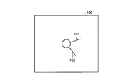
- FIG. 3 is a view showing a display example of the sensitivity reduction unit display image displayed by the display device.
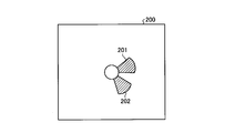
- FIG. 4 is a view showing another display example of the sensitivity reduction unit display image displayed by the display device.
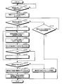
- FIG. 5 is a flowchart showing an outline of the element sensitivity determination process performed by the ultrasonic observation apparatus according to the first embodiment of the present invention.
- FIG. 1 is a block diagram showing a configuration of an ultrasound diagnostic system provided with the ultrasound observation apparatus according to Embodiment 1 of the present invention.
- FIG. 2 is a diagram showing an outline of the determination process performed by the determination unit of the ultrasonic observation apparatus according to the first embodiment of the present invention.
- FIG. 3 is a view showing a
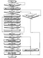
- FIG. 6 is a flowchart showing an outline of the element sensitivity determination process performed by the ultrasound observation apparatus according to the second embodiment of the present invention.
- FIG. 7 is a diagram for explaining the near area.
- FIG. 8 is a diagram showing an example of the setting method of the near region.
- FIG. 9 is a diagram for describing changing the vicinity region of the candidate element according to the depth.
- FIG. 10 is a diagram showing a display example of a sensitivity reduction portion display image according to the first modification of the second embodiment of the present invention.
- FIG. 11 is a diagram showing another example of the setting method of the near region.
- FIG. 12 is a diagram showing an outline of processing of the determination unit in the second modification of the second embodiment of the present invention.
- FIG. 13 is a flowchart showing an outline of the element determination processing performed by the ultrasonic observation apparatus according to the third embodiment of the present invention.
- FIG. 1 is a block diagram showing a configuration of an ultrasound diagnostic system provided with the ultrasound observation apparatus according to Embodiment 1 of the present invention.
- the ultrasound diagnostic system 1 shown in the figure transmits an ultrasound wave to a subject to be observed, and receives an ultrasound wave reflected by the subject.
- generated are provided.
- the ultrasonic probe 2 converts an electrical pulse signal received from the ultrasonic observation apparatus 3 into an ultrasonic pulse (acoustic pulse) at its tip and irradiates the object with the ultrasonic pulse, and
- the ultrasonic transducer 21 has an ultrasonic transducer 21 for converting an acoustic echo into an electrical echo signal (ultrasound signal) that is expressed by a voltage change.
- the ultrasonic transducer 21 is an electronic scanning type having a plurality of elements arranged in an array. The element is configured using a piezoelectric material such as lead zirconate titanate (PZT), lead titanate (PT), or lead niobate, and converts ultrasonic waves by converting mechanical energy and electrical energy. Send and receive.
- PZT lead zirconate titanate
- PT lead titanate
- lead niobate lead niobate
- the ultrasound probe 2 may be an ultrasound endoscope further having an imaging optical system and an imaging element, or may be a small diameter miniature probe not having an optical system. Further, the ultrasonic probe 2 may be of an extracorporeal type in which ultrasonic waves are irradiated from the body surface of the subject as well as the type inserted into the body of the subject.
- the ultrasound observation apparatus 3 includes a transmission unit 31, a reception unit 32, a signal processing unit 33, an ultrasound image generation unit 34, a determination unit 35, a sensitivity reduction unit display image generation unit 36, and an input unit 37. , Control unit 38, and storage unit 39.
- the transmission unit 31 is electrically connected to the ultrasound probe 2 and transmits a transmission signal (pulse signal) to the ultrasound transducer 21.
- the frequency band of the pulse signal transmitted by the transmission unit 31 may be a wide band that substantially covers the linear response frequency band of the electroacoustic conversion of the pulse signal in the ultrasonic transducer 21 to the ultrasonic pulse.
- the transmission unit 31 transmits a transmission signal to a plurality of elements constituting one sound ray while controlling the transmission timing to each element.
- the plurality of elements receiving the transmission signal in this manner emit ultrasonic beams.
- the transmitter 31 transmits various control signals output from the controller 38 to the ultrasound probe 2.
- the power of the transmission signal transmitted by the transmission unit 31 when detecting an element with reduced sensitivity (sensitivity reduction element) may be stronger than the power of the transmission signal at the time of inspection.
- the receiving unit 32 receives an echo signal, which is an electrical reception signal, from the ultrasonic transducer 21 and performs A / D conversion to convert data of a digital radio frequency (RF) signal (hereinafter referred to as RF data). Generate).
- the receiving unit 32 also has a function of receiving various types of information including the identification ID from the ultrasound probe 2.
- the signal processing unit 33 generates digital ultrasound image reception data based on the RF data received from the receiving unit 32. Specifically, the signal processing unit 33 performs known processing such as digital beam forming (DBF) processing for adjusting and adding phases of a plurality of RF data, envelope detection processing, and logarithmic conversion processing, and Generate reception data for ultrasound image.
- the ultrasonic image reception data is a plurality of line data (sound ray data) in which the amplitude or intensity of an echo signal indicating the intensity of reflection of ultrasonic pulses is arranged along the transmission / reception direction (depth direction) of ultrasonic pulses. It consists of
- the signal processing unit 33 outputs the generated reception data for ultrasound image for one frame to the ultrasound image generation unit 34.
- the ultrasound image generation unit 34 generates ultrasound image data based on the reception data for ultrasound image received from the signal processing unit 33.
- the ultrasound image generation unit 34 has a digital scan converter (DSC) that converts the ultrasound image reception data into data according to the display method of the display device 4.
- the ultrasound image generation unit 34 further performs known signal processing such as gain processing and contrast processing to generate ultrasound image data.
- This ultrasound image data is so-called B mode image data.
- the B-mode image is a grayscale image in which the values of R (red), G (green), and B (blue), which are variables when an RGB color system is adopted as a color space, are matched.
- the determination unit 35 analyzes the RF data received from the reception unit 32 to determine whether each element included in the ultrasonic transducer 21 is a sensitivity reducing element. After detecting the amplitude of the RF data as a sensitivity value, the determination unit 35 compares the sensitivity value with a predetermined threshold value, and detects an element having a sensitivity value smaller than the threshold value as a factor causing a drop in reception sensitivity (hereinafter referred to as sensitivity It is determined that the reduction element). The determination unit 35 writes, for example, sensitivity information in which the element determined as the sensitivity reducing element is 1 and the other elements are 0 in the storage unit 39 and stores the information.
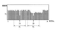
- FIG. 2 is a diagram showing an outline of the determination process of the determination unit 35.
- sensitivity values of N (N: integer) elements of the ultrasonic transducer 21 are shown.
- This determination process is intended to determine whether each element is a sensitivity reducing element before the inspection of the object by the ultrasound diagnostic system 1 is performed.
- This determination process is performed in a state where the distal end portion of the ultrasonic probe 2 is held in the air after the user connects the ultrasonic probe 2 to the ultrasonic observation apparatus 3.
- an echo signal received by the receiving unit 32 with respect to the transmission signal transmitted by the transmitting unit 31 is reflected at the interface between the ultrasonic transducer 21 and air. It is an echo signal that has returned.
- the sensitivity reduction unit display image generation unit 36 performs processing such as coordinate conversion to coordinates corresponding to the ultrasonic image using the sensitivity information for each element stored in the storage unit 39 to obtain the position of the sensitivity reduction element.
- the display data indicating the image area whose sensitivity has been lowered in the ultrasound image is generated.
- the image (hereinafter referred to as sensitivity reduced portion display image) displayed by the display device based on the display data is an image in which the position of the element in the ultrasonic transducer 21 is the same as the ultrasonic image.
- FIG. 3 is a view showing a display example of the sensitivity reduction unit display image displayed by the display device 4.
- the sensitivity reduced portion display image 100 shown in the figure is an image generated corresponding to the detection result shown in FIG. 2, and the sensitivities respectively corresponding to the positions of the two elements determined by the determination unit 35 as the sensitivity reduced elements.
- the reduced parts 101 and 102 are displayed.
- the sensitivity reduced portion display image 100 may be displayed in reverse in black and white in FIG.
- the sensitivity reduction parts 101 and 102 may be displayed in a predetermined color other than black.
- FIG. 4 is a diagram showing another display example of the sensitivity reduction unit display image displayed by the display device 4.
- the sensitivity reduced portion display image 200 shown in the figure is an image generated corresponding to the detection result shown in FIG. 2, and is an image area affected by the two elements determined by the determination unit 35 as the sensitivity reduced element. Is displayed as the sensitivity reduction units 201 and 202.
- the sensitivity reduced portion display image 200 may be displayed in reverse in black and white in FIG.
- the sensitivity reduction units 201 and 202 may be displayed with a predetermined color, or may be displayed with a predetermined pattern.
- the user who has viewed the sensitivity reduction portion display image 100 or 200 can intuitively grasp the position of the sensitivity reduction portion in the ultrasound image.
- the input unit 37 is configured using a user interface such as a keyboard, a button, a mouse, a trackball, a touch panel, and a touch pad, and receives input of various operation signals. As one of various operation signals, a signal instructing start of sensitivity determination processing of the element of the ultrasonic transducer 21 is included.
- the control unit 38 reads the information stored in the storage unit 39 from the storage unit 39 and executes various arithmetic processing related to the operation method of the ultrasound observation apparatus 3 to perform ultrasound diagnosis including the ultrasound observation apparatus 3 Integrate and control the operation of the system 1.
- the storage unit 39 stores information such as a threshold of a sensitivity value to be referred to when the determination unit 35 makes a determination, and a result of the determination made by the determination unit 35 for each element.
- the threshold of the sensitivity value stored in the storage unit 39 may be different depending on the type of the ultrasound probe 2.
- the storage unit 39 stores various programs for operating the ultrasound diagnostic system 1 and data including various parameters and the like necessary for the operation of the ultrasound diagnostic system 1.
- the various programs include an operating program for executing the operating method of the ultrasound diagnostic system 1.
- the various programs can be stored in a computer readable storage medium such as a hard disk, a flash memory, a CD-ROM, a DVD-ROM, a flexible disk and the like, and can be widely distributed. Also, various programs can be acquired by downloading via a communication network.
- the communication network referred to here is realized by, for example, an existing public line network, LAN (Local Area Network), WAN (Wide Area Network) or the like, and may be wired or wireless.
- the ultrasound observation apparatus 3 having the above configuration is a dedicated integration that executes a specific function such as a general processor such as a central processing unit (CPU) or an application specific integrated circuit (ASIC) or a field programmable gate array (FPGA).
- the circuit is realized using a ROM (Read Only Memory) in which various programs and the like are previously installed, and a RAM (Random Access Memory) storing operation parameters and data of each process.
- ROM Read Only Memory
- RAM Random Access Memory
- the display device 4 receives and displays data signals of the ultrasonic image generated by the ultrasonic observation device 3 and the display image of the sensitivity reduction unit via the video cable.
- the display device 4 is configured using a monitor such as liquid crystal or organic EL (Electro Luminescence).
- FIG. 5 is a flowchart showing an outline of the element sensitivity determination process performed by the ultrasonic observation apparatus 3 having the above configuration. In the flowchart shown below, it is assumed that the ultrasonic observation apparatus 3 is powered on.
- the control unit 38 causes the display device 4 to display a start message of the element sensitivity determination process (step S102).
- This start message is, for example, "Start the element sensitivity determination process of the element of the ultrasonic probe. Please hold the tip of the ultrasonic probe in the air and press the OK button.”
- Step S101: No the ultrasound observation apparatus 3 repeats Step S101.
- the control unit 38 sets the counter i to the initial value 1 (step S104). Subsequently, the transmission unit 31 selects an element of the element number i (hereinafter referred to as an element i) among the plurality of elements included in the ultrasonic transducer 21 and transmits a transmission signal to the element i (step S105). Although the case where the transmitting unit 31 transmits the transmission signal to the element 1 when the input unit 37 receives the input of the start instruction signal has been described here, the control unit 38 detects the connection of the ultrasound probe 2 When this occurs, the transmitter 31 may automatically start transmitting a transmission signal to the element 1.
- the receiving unit 32 receives an echo signal from the ultrasonic transducer 21, performs A / D conversion to generate RF data, and outputs the RF data to the determination unit 35 (step S106).
- the determination unit 35 uses the RF data received from the reception unit 32 to determine whether or not the element i is a sensitivity reducing element, and stores sensitivity information according to the determination result in the storage unit 39 (step S107).
- the determination unit 35 calculates the sensitivity value of the element i from the amplitude of the RF data, and when the sensitivity value is lower than the threshold value, determines the element i as a sensitivity reduction element. In the case shown in FIG. 2, the determination unit 35 determines that the two elements 10 and 20 are sensitivity reducing elements.
- control unit 38 determines whether the counter i is smaller than the number N of elements (step S108). If the counter i is smaller than N (step S108: YES), the control unit 38 increments the counter i by 1 (step S109) and performs control to return to step S105 because the determination processing for all elements is not completed. On the other hand, when the counter i is not smaller than N (step S108: No), the control unit 38 performs control to shift to step S110 because the determination processing for all elements is completed.
- step S110 If there is a sensitivity reduction element as a result of the determination by the determination unit 35 (step S110: Yes), the sensitivity reduction unit display image generation unit 36 generates data of the sensitivity reduction unit display image with reference to the storage unit 39. (Step S111). Subsequently, the control unit 38 causes the display device 4 to display the sensitivity reduction unit display image (step S112).
- the display device 4 displays, for example, the sensitivity reduction unit display image 100 shown in FIG. 3 or the sensitivity reduction unit display image 200 shown in FIG. 4. At this time, the control unit 38 may cause the display device 4 to display a message notifying that the sensitivity lowering element is present, together with the sensitivity lowering unit display image.
- the ultrasound observation apparatus 3 ends the series of processes.
- the control unit 38 causes the display device 4 to end the display of the sensitivity reduction unit display image. It is also good. In addition, after a predetermined time has elapsed since the display device 4 starts displaying the sensitivity reduction portion display image, the control unit 38 may cause the display device 4 to end the display of the sensitivity reduction portion display image.
- step S110 when there is no sensitivity reducing element (step S110: No), the control unit 38 causes the display device 4 to display a message notifying that there is no sensitivity reducing element (step S113).
- step S113 instead of displaying a message on the display device 4, a means for outputting sound or a means for blinking a lamp may be used to notify that there is no sensitivity reducing element.
- the ultrasound observation apparatus 3 ends the series of processes.
- step S103 when the input unit 37 does not receive the input of the start instruction signal (step S103: No), when a predetermined time has elapsed after the start message is displayed (step S114: Yes), the ultrasonic observation is performed.
- the device 3 ends the series of processes.
- step S114: No the ultrasound observation apparatus 3 returns to step S103.
- the ultrasonic observation apparatus differs from that of the first embodiment in the element sensitivity determination process in the determination unit.
- the configuration of the ultrasound diagnostic system according to the second embodiment is the same as that of the first embodiment.
- components of the ultrasound diagnostic system will be described with the same reference numerals as in the first embodiment.
- FIG. 6 is a flowchart showing an outline of the element sensitivity determination process performed by the ultrasonic observation apparatus according to the second embodiment.
- the processes of steps S201 to S206 correspond to the processes of steps S101 to S106 described in the first embodiment, respectively.
- step S207 the determination unit 35 calculates the sensitivity value of the element i using the RF data received from the reception unit 32 and stores the sensitivity value in the storage unit 39 (step S207). Thereafter, the control unit 38 determines whether the counter i is smaller than the number N of elements (step S208). If the counter i is smaller than N (step S208: Yes), the control unit 38 increments the counter i by 1 (step S209), and performs control to return to step S205. On the other hand, when the counter i is not smaller than N (step S208: No), the control unit 38 performs control to shift to step S210.
- step S210 the determination unit 35 compares the sensitivity value of each element with the threshold value Th, and extracts an element having a sensitivity value smaller than the threshold value Th as a candidate element to be a candidate for the sensitivity reduction element (step S210).
- the determination unit 35 extracts a candidate element (step S211: Yes)
- the determination unit 35 reads out the sensitivity value of the element in the vicinity region of the candidate element from the storage unit 39, and averages the read sensitivity values of the read element Is calculated (step S212).
- FIG. 7 is a diagram for explaining the near area.
- FIG. 7 shows the sensitivity values of N elements of the ultrasonic transducer 21 as in FIG. 2, and shows the case where the sensitivity values of the elements 10 and 20 are below the threshold value Th.
- the determination unit 35 extracts the element 10 and the element 20 as candidate elements, sets an area including a predetermined number of elements centering on each candidate element as a near area, and determines the sensitivity value of the elements in the near area. Calculate the average.
- the sensitivity values of the neighboring region D 1 of the element 10 is relatively higher than the sensitivity values of the neighboring region D 2 of the element 20. Accordingly, the average sensitivity value of the elements in the neighboring region D 1 is greater than the average sensitivity value of the elements in the neighboring region D 2.
- the number of elements included in the near region may be, for example, a transmission numerical aperture set to generate an ultrasound image, or may be a number close to the transmission numerical aperture. Such numbers are given as a function of the transmit numerical aperture.
- the elements included in the near area may not be all elements in the area, and may be thinned at predetermined intervals in the area, for example, or a predetermined number of elements may be randomly selected in the area. . Also, the sensitivity value of the candidate element may not be included in the average.
- the determination unit 35 determines that the candidate element whose average of the elements in the calculated near region is smaller than the second threshold is the sensitivity reduction element (step S213).
- the second threshold at this time may be the same as or different from the threshold Th.
- the sensitivity reduction unit display image generation unit 36 If it is determined that there is a sensitivity reduction element (step S214: Yes), the sensitivity reduction unit display image generation unit 36 generates data of the sensitivity reduction unit display image (step S215). If the case shown in FIG. 7, for example, one average sensitivity value of the elements in the neighboring region D 1 is greater than the second threshold value, the average sensitivity value of the elements in the neighboring region D 2 smaller than the second threshold value, The determination unit 35 determines that only the element 20 among the two candidate elements is the sensitivity reduction element.
- the control unit 38 causes the display device 4 to display the sensitivity reduction unit display image (step S216).
- the display example of the sensitivity reduction portion display image when only the element 20 is determined as the sensitivity reduction element is an image obtained by removing the sensitivity reduction portion 101 from the sensitivity reduction portion display image 100 shown in FIG. 7 is an image obtained by removing the sensitivity reduction unit 201 from the sensitivity reduction unit display image 200 shown in FIG.
- the ultrasound observation apparatus 3 ends the series of processes.
- the control unit 38 causes the display device 4 to end the display of the sensitivity reduction unit display image. It is also good. Alternatively, after a predetermined time has elapsed since the display device 4 displayed the sensitivity reduction portion display image, the control unit 38 may cause the display device 4 to end the display of the sensitivity reduction portion display image.
- step S214 when there is no sensitivity reducing element (step S214: No), the control unit 38 causes the display device 4 to display a message notifying that there is no sensitivity reducing element (step S217).
- step S217 the ultrasound observation apparatus 3 ends the series of processes.
- step S211 when the determination unit 35 does not extract a candidate element (step S211: No), the control unit 38 performs control to shift to step S217.
- step S203 when the input unit 37 does not receive the input of the start instruction signal (step S203: No), when a predetermined time has elapsed after the start message is displayed (step S218: Yes), the ultrasonic observation apparatus 3 finishes a series of processing. When the predetermined time has not elapsed in step S218 (step S218: No), the ultrasound observation apparatus 3 returns to step S203.
- the user can intuitively grasp the influence on the ultrasonic image caused by the decrease in the sensitivity of the ultrasonic element of the ultrasonic probe. It will be possible.
- the ultrasonic wave is used to determine whether or not the element is a sensitivity reducing element, including the sensitivity information of the element included in the vicinity region with respect to the candidate element of the sensitivity reducing element. It is possible to more accurately detect the sensitivity-reduced portion that affects the image.
- the second threshold may be set according to the statistical value.
- the value of the second threshold may be changed according to the number of elements constituting the population.
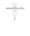
- the near region may be set in accordance with the reception numerical aperture at the time of generating the ultrasonic image. As shown in FIG. 8, the reception numerical aperture may be set larger as the depth at which the ultrasonic waves reach is larger. Therefore, the number of elements in the near region may be set larger as the depth is larger.
- FIG. 9 is a diagram for describing changing the vicinity region of the candidate element according to the depth. In the first modification, the determination unit 35 may set the second threshold used for the determination in accordance with the depth.
- FIG. 10 is a view showing a display example of the sensitivity reduction portion display image in the first modification.
- the reduced sensitivity portion display image 300 shown in the figure displays two sensitivity reduced portions 301 and 302.
- the lengths of the lines of the reduced sensitivity portion 301 and the reduced sensitivity portion 302 are different. This indicates that the sensitivity reduction portion 302 has an influence of the sensitivity reduction to a region where the depth is larger than that of the sensitivity reduction portion 301.
- the user can grasp not only the sensitivity reduction position but also the range in the depth direction where the sensitivity reduction is applied.
- the near region is set according to the depth, and the presence or absence of the sensitivity reduction is determined for each depth, so that more detailed and highly accurate sensitivity reduction information can be provided.
- the near region may be set based on the magnitude relationship between the reception numerical aperture and the transmission numerical aperture. As shown in FIG. 11, at the time of ultrasonic image generation, the transmission numerical aperture may be fixed and the reception numerical aperture may be changed according to the depth. In such a case, the smaller one of the transmission numerical aperture and the reception numerical aperture may be used to set the near region for each depth.
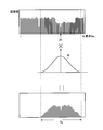
- FIG. 12 is a diagram showing an outline of processing of the determination unit 35 in the second modification.
- the determination unit 35 multiplies the sensitivity value of the near region by a weighting factor, and calculates a statistical value such as an average for the multiplication result.
- the weighting factor W has a larger value as the distance from the candidate element increases with the distance from the candidate element.
- the sensitivity reduction element is determined using the weighted sensitivity value, it is possible to perform the determination reflecting the contribution of the elements included in the near region.
- the ultrasonic observation apparatus performs a process of determining whether each element is a sensitivity reducing element or not, using an ultrasonic beam irradiated when generating an ultrasonic image.
- the configuration of the ultrasound diagnostic system according to the third embodiment is the same as that of the first embodiment.
- components of the ultrasound diagnostic system will be described with the same reference numerals as in the first embodiment.
- FIG. 13 is a flowchart showing an outline of the element determination processing performed by the ultrasound observation apparatus according to the third embodiment.
- the processes of steps S301 to S304 correspond to the processes of steps S101 to S104 described in the first embodiment, respectively.
- step S305 in order to cause the ultrasonic transducer 21 to output the ultrasonic beam, the transmission unit 31 controls the transmission timing for a plurality of elements for the transmission numerical aperture centered on the element i, and transmits the transmission signal. It transmits (step S305).
- the receiving unit 32 receives an echo signal from the ultrasonic transducer 21, generates A / D data by performing A / D conversion, and outputs the RF data to the determination unit 35 (step S306).
- the determination unit 35 calculates sensitivity values of a plurality of elements using the RF data received from the reception unit 32, calculates the average of those sensitivity values, and stores the average in the storage unit 39 (step S307).
- the determining unit 35 determines whether the element i is a sensitivity reducing element by comparing the average of the sensitivity values with the threshold value, and stores the determination result in the storage unit 39 (step S308).
- control unit 38 determines whether the counter i is smaller than the number N of elements (step S309). If the counter i is smaller than N (step S309: Yes), the control unit 38 increments the counter i by 1 (step S310), and performs control to return to step S305. On the other hand, when the counter i is not smaller than N (step S309: No), the control unit 38 performs control to shift to step S311.
- steps S311 to S315 correspond to steps S110 to S114 described in the first embodiment, respectively.
- the display mode of the sensitivity reduction portion display image is the same as the sensitivity reduction portion display image 100 (see FIG. 3) described in the first embodiment.
- the sensitivity reduction units 101 and 102 correspond to the sound rays of the ultrasonic image.
- the user intuitively grasps the influence on the ultrasonic image caused by the decrease in sensitivity of the ultrasonic element of the ultrasonic probe. It will be possible to
- the determination unit 35 calculates the average of the luminance value of each pixel after imaging the RF data by the same process as the ultrasound image, and calculates this average The presence or absence of a decrease in sensitivity of the element may be determined by using it as sensitivity information.
- the sensitivity reduction unit may be displayed while the examination is performed using the ultrasound diagnostic system 1.
- the sensitivity reduction unit display image generation unit 36 refers to the storage unit 39 to specify the sensitivity reduction element, and the ultrasonic image
- the data of the sensitivity reduced portion display image is generated in accordance with the display of.
- the sensitivity reduction unit display image generation unit 36 also changes the display mode of the sensitivity reduction unit display image according to the scroll.
- the control unit 38 causes the display device 4 to display the sensitivity reduction unit display image side by side with the ultrasound image.
- the control unit 38 may cause the display device 4 to display the sensitivity reduction unit display image smaller than the ultrasound image.
- the control unit 38 causes the display device 4 to end the display of the sensitivity reduction unit display image.
- the ultrasound observation apparatus may further include a superimposed image generation unit that generates data of a superimposed image in which the ultrasound image and the sensitivity reduction unit display image are superimposed.
- a superimposed image generation unit that generates data of a superimposed image in which the ultrasound image and the sensitivity reduction unit display image are superimposed.
- the input unit 37 receives the display instruction input of the sensitivity reduction unit during the examination
- the sensitivity reduction unit display image generation unit 36 generates the data of the sensitivity reduction unit display image in the same manner as described above, and then the superimposed image is generated.
- the generation unit superimposes this data on the data of the ultrasound image to generate data of the superimposed image.
- the superimposed image may be displayed by giving visual information such as color, saturation, lightness, pattern or pattern to the reduced sensitivity portion, or by increasing the transparency of the decreased sensitivity portion to make it semitransparent It is also good.
- the user can grasp the sensitivity reduction portion even during the inspection and can use it in the inspection or diagnosis.
Landscapes
- Engineering & Computer Science (AREA)
- Health & Medical Sciences (AREA)
- Life Sciences & Earth Sciences (AREA)
- Physics & Mathematics (AREA)
- Radar, Positioning & Navigation (AREA)
- Remote Sensing (AREA)
- Animal Behavior & Ethology (AREA)
- Medical Informatics (AREA)
- Veterinary Medicine (AREA)
- Biophysics (AREA)
- Nuclear Medicine, Radiotherapy & Molecular Imaging (AREA)
- Pathology (AREA)
- Radiology & Medical Imaging (AREA)
- Biomedical Technology (AREA)
- Heart & Thoracic Surgery (AREA)
- Public Health (AREA)
- Molecular Biology (AREA)
- Surgery (AREA)
- General Health & Medical Sciences (AREA)
- Computer Networks & Wireless Communication (AREA)
- General Physics & Mathematics (AREA)
- Acoustics & Sound (AREA)
- Computer Vision & Pattern Recognition (AREA)
- Ultra Sonic Daignosis Equipment (AREA)
Priority Applications (1)
| Application Number | Priority Date | Filing Date | Title |
|---|---|---|---|
| US16/901,145 US11432807B2 (en) | 2017-12-20 | 2020-06-15 | Ultrasound imaging system, operating method of ultrasound imaging system, and computer-readable recording medium |
Applications Claiming Priority (2)
| Application Number | Priority Date | Filing Date | Title |
|---|---|---|---|
| JP2017-244257 | 2017-12-20 | ||
| JP2017244257A JP6954826B2 (ja) | 2017-12-20 | 2017-12-20 | 超音波観測装置、超音波観測装置の作動方法および超音波観測装置の作動プログラム |
Related Child Applications (1)
| Application Number | Title | Priority Date | Filing Date |
|---|---|---|---|
| US16/901,145 Continuation US11432807B2 (en) | 2017-12-20 | 2020-06-15 | Ultrasound imaging system, operating method of ultrasound imaging system, and computer-readable recording medium |
Publications (1)
| Publication Number | Publication Date |
|---|---|
| WO2019124524A1 true WO2019124524A1 (ja) | 2019-06-27 |
Family
ID=66994763
Family Applications (1)
| Application Number | Title | Priority Date | Filing Date |
|---|---|---|---|
| PCT/JP2018/047107 Ceased WO2019124524A1 (ja) | 2017-12-20 | 2018-12-20 | 超音波観測装置、超音波観測装置の作動方法および超音波観測装置の作動プログラム |
Country Status (3)
| Country | Link |
|---|---|
| US (1) | US11432807B2 (https=) |
| JP (1) | JP6954826B2 (https=) |
| WO (1) | WO2019124524A1 (https=) |
Cited By (1)
| Publication number | Priority date | Publication date | Assignee | Title |
|---|---|---|---|---|
| JP2024045777A (ja) * | 2020-05-15 | 2024-04-02 | キヤノンメディカルシステムズ株式会社 | 超音波診断装置 |
Families Citing this family (3)
| Publication number | Priority date | Publication date | Assignee | Title |
|---|---|---|---|---|
| JP2022178120A (ja) * | 2021-05-19 | 2022-12-02 | コニカミノルタ株式会社 | 超音波診断装置、超音波診断装置の制御方法、及び、超音波診断装置の制御プログラム |
| JP7725384B2 (ja) * | 2022-01-31 | 2025-08-19 | キヤノンメディカルシステムズ株式会社 | 超音波診断装置及びプローブ点検装置 |
| JP7825337B1 (ja) * | 2025-05-20 | 2026-03-06 | 本多電子株式会社 | 超音波ソナー装置 |
Citations (5)
| Publication number | Priority date | Publication date | Assignee | Title |
|---|---|---|---|---|
| JPH09313488A (ja) * | 1996-05-31 | 1997-12-09 | Matsushita Electric Ind Co Ltd | 超音波診断装置 |
| JP2008220690A (ja) * | 2007-03-13 | 2008-09-25 | Toshiba Corp | 超音波診断装置 |
| JP2013165880A (ja) * | 2012-02-16 | 2013-08-29 | Hitachi Aloka Medical Ltd | 超音波診断装置 |
| JP2015053961A (ja) * | 2013-09-10 | 2015-03-23 | セイコーエプソン株式会社 | 超音波測定装置、超音波画像装置、及び超音波測定方法 |
| JP2015097619A (ja) * | 2013-11-19 | 2015-05-28 | 株式会社東芝 | 超音波診断装置及び超音波診断装置用のプログラム |
Family Cites Families (3)
| Publication number | Priority date | Publication date | Assignee | Title |
|---|---|---|---|---|
| JP3658429B2 (ja) | 1995-06-23 | 2005-06-08 | 株式会社東芝 | 超音波診断装置 |
| JP2002159492A (ja) * | 2000-11-27 | 2002-06-04 | Aloka Co Ltd | 超音波診断装置及び素子試験方法 |
| JP2009178262A (ja) | 2008-01-29 | 2009-08-13 | Toshiba Corp | 超音波診断装置 |
-
2017
- 2017-12-20 JP JP2017244257A patent/JP6954826B2/ja active Active
-
2018
- 2018-12-20 WO PCT/JP2018/047107 patent/WO2019124524A1/ja not_active Ceased
-
2020
- 2020-06-15 US US16/901,145 patent/US11432807B2/en active Active
Patent Citations (5)
| Publication number | Priority date | Publication date | Assignee | Title |
|---|---|---|---|---|
| JPH09313488A (ja) * | 1996-05-31 | 1997-12-09 | Matsushita Electric Ind Co Ltd | 超音波診断装置 |
| JP2008220690A (ja) * | 2007-03-13 | 2008-09-25 | Toshiba Corp | 超音波診断装置 |
| JP2013165880A (ja) * | 2012-02-16 | 2013-08-29 | Hitachi Aloka Medical Ltd | 超音波診断装置 |
| JP2015053961A (ja) * | 2013-09-10 | 2015-03-23 | セイコーエプソン株式会社 | 超音波測定装置、超音波画像装置、及び超音波測定方法 |
| JP2015097619A (ja) * | 2013-11-19 | 2015-05-28 | 株式会社東芝 | 超音波診断装置及び超音波診断装置用のプログラム |
Cited By (2)
| Publication number | Priority date | Publication date | Assignee | Title |
|---|---|---|---|---|
| JP2024045777A (ja) * | 2020-05-15 | 2024-04-02 | キヤノンメディカルシステムズ株式会社 | 超音波診断装置 |
| JP7796153B2 (ja) | 2020-05-15 | 2026-01-08 | キヤノンメディカルシステムズ株式会社 | 超音波診断装置 |
Also Published As
| Publication number | Publication date |
|---|---|
| JP2019107419A (ja) | 2019-07-04 |
| US11432807B2 (en) | 2022-09-06 |
| JP6954826B2 (ja) | 2021-10-27 |
| US20200305848A1 (en) | 2020-10-01 |
Similar Documents
| Publication | Publication Date | Title |
|---|---|---|
| US11432807B2 (en) | Ultrasound imaging system, operating method of ultrasound imaging system, and computer-readable recording medium | |
| WO2020075609A1 (ja) | 超音波診断装置および超音波診断装置の制御方法 | |
| EP3865070B1 (en) | Ultrasound diagnosis device and ultrasound diagnosis device control method | |
| JPWO2013011800A1 (ja) | 超音波診断装置及び超音波探触子の振動子劣化検出方法 | |
| JPWO2020075575A1 (ja) | 超音波診断装置および超音波診断装置の制御方法 | |
| JP7191949B2 (ja) | 超音波システムおよび超音波システムの制御方法 | |
| JP6443056B2 (ja) | 超音波診断装置 | |
| JP6589619B2 (ja) | 超音波診断装置 | |
| US11723627B2 (en) | Ultrasound imaging system, operating method of ultrasound imaging system, and computer-readable recording medium | |
| US20140200451A1 (en) | Ultrasonic measuring device, ultrasonic diagnosis device, ultrasonic measurement sheet, and measuring method | |
| US12611164B2 (en) | Ultrasound diagnostic apparatus with function for highlight-displaying excrement region in ultrasound image and control method for ultrasound diagnostic apparatus | |
| JP2019208591A (ja) | 超音波診断装置および自動保存制御プログラム | |
| US20240108307A1 (en) | Ultrasound diagnostic apparatus and control method for ultrasound diagnostic apparatus | |
| JP2011087841A (ja) | 超音波診断装置 | |
| WO2019124171A1 (ja) | 超音波観測装置、超音波観測装置の作動方法および超音波観測装置の作動プログラム | |
| US12414757B2 (en) | Ultrasound diagnostic apparatus and control method for ultrasound diagnostic apparatus | |
| JP7251843B1 (ja) | 超音波診断装置及びそのためのプログラム | |
| JP2024064182A (ja) | 超音波診断装置および超音波診断装置の制御方法 | |
| JP7190851B2 (ja) | 超音波観測装置、超音波観測装置の作動方法、及び超音波観測装置の作動プログラム | |
| WO2023281987A1 (ja) | 超音波システムおよび超音波システムの制御方法 | |
| JP2024039872A (ja) | 超音波診断装置の制御方法および超音波診断装置 | |
| WO2024252739A1 (ja) | 超音波診断装置、目的結果抽出方法及び目的結果抽出プログラム | |
| JP2024025865A (ja) | 超音波診断装置の制御方法および超音波診断装置 | |
| JP2024042416A (ja) | 超音波診断装置および超音波診断装置の制御方法 | |
| JP2024068927A (ja) | 超音波診断システムの制御方法および超音波診断システム |
Legal Events
| Date | Code | Title | Description |
|---|---|---|---|
| 121 | Ep: the epo has been informed by wipo that ep was designated in this application |
Ref document number: 18891595 Country of ref document: EP Kind code of ref document: A1 |
|
| NENP | Non-entry into the national phase |
Ref country code: DE |
|
| 122 | Ep: pct application non-entry in european phase |
Ref document number: 18891595 Country of ref document: EP Kind code of ref document: A1 |