WO2019106993A1 - Dispositif d'affichage d'image virtuelle, boîtier et couvercle d'ouverture - Google Patents
Dispositif d'affichage d'image virtuelle, boîtier et couvercle d'ouverture Download PDFInfo
- Publication number
- WO2019106993A1 WO2019106993A1 PCT/JP2018/038658 JP2018038658W WO2019106993A1 WO 2019106993 A1 WO2019106993 A1 WO 2019106993A1 JP 2018038658 W JP2018038658 W JP 2018038658W WO 2019106993 A1 WO2019106993 A1 WO 2019106993A1
- Authority
- WO
- WIPO (PCT)
- Prior art keywords
- opening
- virtual image
- case
- light
- display light
- Prior art date
Links
Images

Classifications
-
- B—PERFORMING OPERATIONS; TRANSPORTING
- B60—VEHICLES IN GENERAL
- B60K—ARRANGEMENT OR MOUNTING OF PROPULSION UNITS OR OF TRANSMISSIONS IN VEHICLES; ARRANGEMENT OR MOUNTING OF PLURAL DIVERSE PRIME-MOVERS IN VEHICLES; AUXILIARY DRIVES FOR VEHICLES; INSTRUMENTATION OR DASHBOARDS FOR VEHICLES; ARRANGEMENTS IN CONNECTION WITH COOLING, AIR INTAKE, GAS EXHAUST OR FUEL SUPPLY OF PROPULSION UNITS IN VEHICLES
- B60K35/00—Arrangement of adaptations of instruments
-
- G—PHYSICS
- G02—OPTICS
- G02B—OPTICAL ELEMENTS, SYSTEMS OR APPARATUS
- G02B27/00—Optical systems or apparatus not provided for by any of the groups G02B1/00 - G02B26/00, G02B30/00
- G02B27/01—Head-up displays
Definitions
- the present disclosure relates to a virtual image display device that visibly displays a virtual image.
- Patent Document 1 a virtual image display device that displays a virtual image in a visible manner.
- the device disclosed in Patent Document 1 includes a display, a case, and an opening cover.
- the display emits display light.
- the case is a case that accommodates the display, and has an opening that emits the display light to the outside of the case so that the display light is projected to a projection unit located outside the case.
- the opening cover blocks the opening.
- the opening cover of Patent Document 1 is adapted to absorb a part of external light such as sunlight which is to be incident from the outside of the case into the inside of the case.
- the opening cover of Patent Document 1 is formed in a flat plate shape. A part of the external light incident on such a flat aperture cover may be reflected on the surface, and this reflected light may be incident on the eye of the viewer. When such reflected light is incident on the eyes of the viewer in a large amount, the viewer feels dazzling, which makes it difficult to view a virtual image.
- One object disclosed is to provide a virtual image display device with high visibility of a virtual image and a case and an aperture cover used therefor.
- the virtual image display device uses the reflection of display light at the projection unit to visually display a virtual image.
- the virtual image display apparatus includes a display that emits the display light.
- the virtual image display device is a case that accommodates the display, and has a case that emits the display light to the outside of the case so that the display light is projected onto the projection unit located outside the case. , Further provided.
- the virtual image display device further includes an opening cover that closes the opening.
- the opening cover is curved along a parabola so as to be concave toward the display light incident side on the both sides separated by the opening.
- the drawing is It is sectional drawing which shows the mounting state to the vehicle of the HUD apparatus of 1st Embodiment. It is sectional drawing which shows schematic structure of the display part of the HUD apparatus of 1st Embodiment, and a light guide. It is a top view of HUD device of a 1st embodiment. It is sectional drawing for demonstrating the structure of the opening cover of 1st Embodiment. It is a figure corresponding to FIG. 4 in 2nd Embodiment. It is a figure corresponding to FIG. 1 in the modification 1. FIG. It is a figure corresponding to FIG. 1 in the modification 2. FIG.
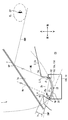
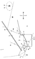
- the virtual image display device according to the first embodiment of the present disclosure is used in a vehicle 1 and is a head-up display device (hereinafter referred to as HUD) accommodated in an instrument panel 2 of the vehicle 1.
- the device is abbreviated to 100).
- the vehicle 1 is not limited to a car as in the present embodiment, but can be broadly understood to include a vehicle such as an aircraft, a ship, a housing that does not move, or the like, as well as a rail car.
- the HUD device 100 projects an image toward the projection unit 7 a set on the front windshield 7 of the vehicle 1.
- the HUD device 100 displays a virtual image so that the image can be viewed visually by the occupant of the vehicle 1 as a viewer. That is, the display light of the image reflected by the projection unit 7a reaches the eye point EP located in the visible area in the passenger sitting in the seat inside the vehicle 1, and the passenger makes a virtual image VRI of the display light. To perceive.
- Examples of various information displayed as a virtual image as an image include information indicating a vehicle state such as a vehicle speed and a remaining amount of fuel, or navigation information such as visibility auxiliary information and road information.
- the front windshield 7 of the vehicle 1 is formed of, for example, glass or synthetic resin in a translucent plate shape.
- the front windshield 7 is disposed to face the upper surface 2a of the instrument panel 2 facing upward, and is inclined, for example, to be separated from the upper surface 2a toward the rear.
- the front windshield 7 forms a projecting portion 7a on which an image is projected in a smooth concave shape or a planar shape.
- the projection unit 7 a may not be provided on the front windshield 7.
- a combiner that is separate from the vehicle 1 may be installed near the front windshield 7 in the vehicle 1, and the projector 7a may be provided in the combiner.
- the visual recognition area is a spatial area where the virtual image VRI displayed by the HUD device 100 can be visually recognized so as to satisfy a predetermined standard, and is also referred to as an eye box.
- the visual recognition area is typically set to overlap with the eyelid EL set in the vehicle 1.
- the eye lip EL is set in an elliptical shape based on an eye range that statistically represents the distribution of the eye position of the driver as the occupant of the vehicle 1 (for details, see JIS D 0021: 1998).
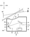
- the HUD device 100 includes a case 10, an opening cover 20, a display 30, a light guide 40, and the like.
- the case 10 is in the form of a hollow box made of, for example, a synthetic resin or metal, and is installed in the instrument panel 2 of the vehicle 1.
- the case 10 has a housing portion 11 configured to house the display 30 and the light guide portion 40, and a case opening 12 opened at the upper side facing the projection portion 7a.
- the entire area of the case opening 12 is closed by an opening cover 20 capable of transmitting display light.
- an instrument panel opening 2 b is opened in the upper surface portion 2 a of the instrument panel 2 of the vehicle 1 at a position corresponding to the case opening 12.
- the display 30 of the present embodiment is a liquid crystal display as shown in FIG.
- the display 30 has a backlight 31 and a liquid crystal panel 32, and is configured by housing them in a box-shaped casing having a light shielding property, for example.
- the display 30 transmits and illuminates the display screen of the liquid crystal panel 32 with the backlight 31 to display an image on the display screen, and emits display light contributing to the display of the virtual image VRI toward the light guide 40. It is supposed to be.
- the liquid crystal panel 32 of the present embodiment is a liquid crystal panel using thin film transistors (TFTs), and is an active matrix liquid crystal panel formed of, for example, a plurality of liquid crystal pixels arranged in a two-dimensional direction. It is.
- the liquid crystal panel 32 can control the transmittance of light of each liquid crystal pixel by the incidence of light from the backlight 31, and can form an image by display light emitted from the display screen. More adjacent liquid crystal pixels are provided with color filters of different colors (for example, red, green and blue), and various colors are realized by combining these.
- the display light emitted from the display 30 is linearly polarized.
- liquid crystal display an organic EL display, a display of a laser scanner system, or various displays of a DLP (Digital Light Processing (registered trademark)) system or the like can be adopted as the display 30.
- DLP Digital Light Processing (registered trademark)
- a plurality of displays 30 may be provided.
- the light guide unit 40 guides the display light incident from the display unit 30 to the projection unit 7a.
- the light guide 40 has, for example, a plane mirror 41 and a concave mirror 42.
- the plane mirror 41 is a reflecting mirror in which a reflecting surface 41 a is formed by depositing aluminum or the like on the surface of a base material made of a synthetic resin or glass.
- the reflecting surface 41a of the plane mirror 41 is formed in a smooth plane shape.
- the display light that has entered the flat mirror 41 from the display 30 is reflected by the reflective surface 41 a toward the concave mirror 42.
- the concave mirror 42 is a reflecting mirror in which a reflecting surface 42 a is formed by depositing aluminum or the like on the surface of a base material made of synthetic resin or glass.
- the reflecting surface 42 a of the concave mirror 42 is formed in a smooth concave shape by curving in a concave shape.
- the display light that has entered the concave mirror 42 is reflected by the reflecting surface 42 a toward the projection unit 7 a and, at the same time, is subjected to a magnifying action that magnifies the virtual image VRI.
- the concave mirror 42 is rotatable around a rotating shaft 43 extending in the left-right direction, so that the vertical position at which the virtual image VRI is displayed can be adjusted.
- the display light reflected by the reflection surface 42 a of the concave mirror 42 in this way is transmitted through the opening cover 20 provided in the case opening 12 and emitted from the inside of the case to the outside of the case to the projection unit 7 a located outside the case. It will be incident.
- the display light reflected by the projection unit 7a reaches the eyes of the occupant, the occupant can visually recognize the virtual image VRI.
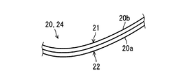
- the opening cover 20 has a rectangular outer shape and is formed in a flexible sheet shape.
- the cover surfaces 21 and 22 on both sides of the opening cover 20 are formed in a mirror-like shape with reduced roughness.
- the opening cover 20 of the present embodiment includes a light transmitting substrate layer 20a and a polarizing layer 20b formed in a stacked state with respect to the light transmitting substrate layer 20a.
- the polarizing layer 20 b is a polarizing element realized by a polarizing film or the like formed in a film shape.
- the polarizing layer 20b is formed, for example, by adding iodine to polyvinyl alcohol, and has a transmission axis and a light shielding axis (in particular, an absorption axis in the present embodiment) substantially orthogonal to each other depending on the orientation direction of iodine molecules.
- the polarizing layer 20b transmits the polarized light along the transmission axis at the maximum transmittance, and absorbs the polarized light along the absorption axis at the maximum absorptivity.
- the absorption axis is set to intersect the polarization direction of the display light emitted from the display 30.
- the transmission axis is set along the polarization direction of the display light.
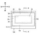
- the opening cover 20 has a holding portion 23 and a cover portion 24.
- the holding portion 23 is provided on the outer peripheral portion of the opening cover 20 and is held by the case 10 as a holding member for holding the opening cover 20.
- a rectangular frame-shaped adhesive sheet 50 is attached to the case side.
- the adhesive sheet 50 has adhesiveness on both sides.
- the adhesive sheet 50 connects the holding portion 23 and the case edge 13 bordering the case opening 12 in the case 10 in a close contact state over the entire circumference.
- the cover portion 24 is configured to be surrounded by the holding portion 23 and to cover the entire case opening 12.
- the cover portion 24 is curved along the case edge 13 by the holding portion 23 being in close contact with the case edge 13.
- the case edge 13 has four sides 13a to 13d in accordance with the outer shape of the opening cover 20.
- the front side 13 a extends linearly in the left-right direction in front of the case opening 12.
- the rear side 13 b extends linearly in the left-right direction at the rear of the case opening 12.
- the front side 13a and the rear side 13b are disposed substantially parallel to each other. In the present embodiment, the front side 13a and the rear side 13b are located at substantially the same height in the vertical direction.
- the left side 13c and the right side 13d are formed in substantially the same shape to form a pair.
- the left side 13 c extends in the front-rear direction in the left with respect to the case opening 12, thereby connecting the front side 13 a and the rear side 13 b.
- the right side 13 d extends in the front-rear direction on the right side of the case opening 12 to connect the front side 13 a and the rear side 13 b.
- the left side 13c and the right side 13d are disposed substantially parallel to each other. In the present embodiment, the left side 13 c and the right side 13 d are located at substantially the same height in the vertical direction.
- the left side 13c and the right side 13d are curved along a parabola so as to be concave toward the space side where the display light is incident on both sides separated by the case opening 12 or the instrument panel opening 2b. It has become a parabola curved side.
- the side on which the display light is incident can also be referred to as the incident side of the display light, the inside of the case, the opposite side to the projection unit 7 a or the lower side of the vehicle 1.
- the cover 24 of the opening cover 20 disposed along the left side 13c and the right side 13d as the parabolic curved side also has a case opening 12 or an instrument panel in a cross section CS along the longitudinal and vertical directions of the vehicle 1 It curves along a parabola so that it may be dented to the incident side of a display light among the both sides separated by the opening 2b.
- the opening cover 20 is curved in a parabolic cylinder shape in which the extension direction of the cylinder is along the left-right direction.
- the cover surface 21 facing the outer side of the case, that is, the upper side has a reflection surface that can reflect external light such as sunlight which is transmitted through the front windshield 7 from the outside of the vehicle 1 and enters. It has a parabolic cylindrical surface.
- a bezel wall 3 of the vehicle 1 is formed around the cover surface 21.
- the bezel wall 3 is formed in the shape of an upright wall covering the entire circumference so as to surround both the openings 2 b and 12.
- the bezel wall 3 is disposed to be in contact with the outermost periphery of the opening cover 20 by filling the gap, and the display light emission side (i.e., the upper side) of both sides separated from the opening cover 20 by the case opening 12 or the instrument panel opening 2b.
- the wall surface of the bezel wall 3 has a light shielding property by being formed in dark color (for example, black) so as to suppress reflection of external light and more preferably absorb external light.
- the bezel wall 3 has a front bezel wall 4 positioned forward with respect to the openings 2 b and 12, and a rear bezel wall 5 positioned rearward with respect to the openings 2 b and 12.
- the front bezel wall 4 is slightly inclined to be positioned rearward as it goes upward, and in a portion in contact with the opening cover 20, the front bezel wall 4 and the outermost periphery of the opening cover 20 form an acute angle ⁇ It is arranged in a way.
- the rear bezel wall 5 is slightly inclined so as to be positioned rearward as it goes upward, and in a portion in contact with the opening cover 20, the rear bezel wall 5 and the outermost periphery of the opening cover 20 have an obtuse angle It is arranged to make ⁇ .
- the apex Vp of the parabola forming the opening cover 20 of the present embodiment is set to be eccentric forward with respect to the center of the opening cover 20.
- the apex Vp of the parabola appears in the aperture cover 20 without being offset.
- the symmetry axis Ap of the parabola is inclined with respect to the horizontal plane to fall back.
- the locus of a virtual ray IMR (see the broken line in FIG. 1) assumed as external light is considered.
- This light beam IMR enters the front windshield 7 of the vehicle 1 obliquely from the front, passes through the front windshield 7, is reflected by the cover surface 21, and passes through the upper end 5a of the rear bezel wall 5 (or It is a ray that passes through so that it is reflected, then is reflected at the reflection position RP of the projection part 7a of the front windshield 7, and passes through the eyelid EL from below, and defines the locus of the ray IMR as a virtual optical path.
- a straight line connecting the upper end 5a of the rear bezel wall 5 and the reflection position RP of the projection unit 7a is defined as a virtual line IML.
- eyedrop EL it is preferable to use an eyedrop of 90th percentile or more and 99th percentile or less such as 90th percentile eyedrops, 95th percentile eyedrops, 99th percentile eyedrops, or the like.
- the imaginary line IML normally extends in a direction going backward as going upward, and the direction of the symmetry axis Ap of the parabola of the opening cover 20 is set along the direction of the imaginary line IML. More preferably, the symmetry axis Ap of the parabola should be set substantially parallel to the imaginary line IML.
- the parabola has a property of collecting light rays incident in parallel to the symmetry axis Ap at a certain point (focus Fp). According to this property, by setting the symmetry axis Ap substantially parallel to the imaginary line IML, the ray IMR along the imaginary line IML passes through the focal point Fp of the parabola. By shielding the lower side of the focal point Fp with a light shielding member such as the front bezel wall 4 or the like, it is possible to suppress external light from entering the eyelid EL after being reflected by the cover surface 21.
- a light shielding member such as the front bezel wall 4 or the like
- the height of the focal point Fp along the symmetry axis Ap is given by a / 4 using the second-order coefficient a of the parabola.
- the height h of the front bezel wall 4 is defined as h, light passing below the focal point Fp can be blocked by the front bezel wall 4 if the conditional expression of h> a / 4 is satisfied. It can be expected to have the effect of suppressing entry into the inside. That is, it is desirable to set the degree of opening of the parabola so that a ⁇ 4 ⁇ h holds.
- the height h of the front bezel wall 4 in this embodiment is a dimension along the vertical direction with respect to the tangent plane IMP from the virtual tangent plane IMP in contact with the apex Vp of the parabola to the upper end 4a of the front bezel wall 4 It is defined.
- the position of the focal point Fp of the parabola is located on the space behind the front bezel wall 4.
- the opening cover 20 for closing the case opening 12 is curved along a parabola so as to be recessed toward the incident side of the display light. Due to this curved form, a part of the external light incident on the aperture cover 20 is reflected and condensed at the same time using the property of a parabola. That is, since the spread of the external light reflected by the opening cover 20 is suppressed, the probability of reaching the eyes of the occupant can be reduced. Therefore, it is also possible to reduce the probability that it becomes difficult for the occupant to visually recognize the virtual image VRI when the occupant feels that the reflected light is dazzling.
- the opening cover 20 is curved in a parabolic cylinder shape.
- this curved form generation of unintended wrinkles and distortion for curving the opening cover 20 can be suppressed, and external light which is shifted in the non-parabolic direction of the parabolic cylinder (for example, the left and right direction of the vehicle)
- external light which is shifted in the non-parabolic direction of the parabolic cylinder (for example, the left and right direction of the vehicle)
- the case opening 12 is disposed in the instrument panel 2 of the vehicle 1 so as to be surrounded by the bezel wall 3 in the upright wall shape.
- Such a bezel wall 3 can block an optical path that reaches the eyes of the occupant after the outside light enters the opening cover 20, so that the occupant feels the reflected light dazzling, and the occupant can make a virtual image VRI.
- the suppression effect of becoming difficult to visually recognize can be heightened.
- the parabola is configured such that a ⁇ 4 ⁇ h is established. Therefore, since the light passing below the focal point Fp of the parabola can be blocked by the front bezel wall 4, the blocking action of blocking the light path reaching the eyes of the occupant by the front bezel wall 4 becomes even higher.
- the symmetry axis Ap of the parabola is substantially parallel to the imaginary line IML.
- external light that is reflected by the aperture cover 20 and reaches the lower end of the eyelid EL just passes through the focal point Fp, so if light below the focal point Fp is blocked by the bezel wall 3, it is efficient It is possible to suppress the entrance of external light to eye Rip EL. Therefore, the probability that the outside light reaches the eyes of the occupant is further reduced, and the suppression effect of making it difficult for the occupant to visually recognize the virtual image VRI is remarkable.
- the aperture cover 20 has a polarizing layer 20b as a polarizing element.
- the outside light enters the inside of the case and is converted to heat, thereby reducing the life of the HUD device 100 and suppressing the occupant from looking into the inside of the case. it can.
- the left side 13 c and the right side 13 d as parabola curved sides are provided at the case edge 13 which borders the case opening 12, whereby the case opening 12 is covered by the opening cover 20.
- the opening cover 20 can be easily curved along a parabola by holding the opening cover 20 along the sides 13 c and 13 d when the opening cover 20 is closed. Therefore, the HUD device 100 with high visibility of the virtual image VRI can be easily provided.
- the cover portion 24 is curved along a parabola so as to be recessed toward the incident side of the display light. Due to this curvature, a part of the external light incident on the aperture cover 20 is reflected and condensed at the same time using the property of a parabola. That is, since the spread of the external light reflected by the opening cover 20 is suppressed, the probability of reaching the eyes of the occupant can be reduced. Therefore, it is also possible to reduce the probability that it becomes difficult for the occupant to visually recognize the virtual image VRI when the occupant feels that the reflected light is dazzling.
- the second embodiment is a modification of the first embodiment.
- the second embodiment will be described focusing on differences from the first embodiment.
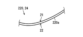
- the aperture cover 220 of the second embodiment has a polycarbonate sheet 220 a that causes a phase difference in display light.
- the polycarbonate sheet 220a is formed to have flexibility by rolling a polycarbonate resin with a plurality of rollers.
- the polycarbonate sheet 220 a is a birefringent material sheet in which the refractive index along the rolling direction and the refractive index along the orthogonal direction orthogonal to the rolling direction are different from each other. Due to the difference in refractive index, the polycarbonate sheet 220a causes a phase difference between the polarization component in the rolling direction and the polarization component in the orthogonal direction in the display light.
- the aperture cover 220 includes the polycarbonate sheet 220 a that causes the display light to have a phase difference.
- the polycarbonate sheet 220a optimizes the polarization state of the display light. As a result, it is possible to increase the reflectance of the display light in the projection unit 7 a or to increase the transmittance of the display light in the polarized sunglasses worn by the occupant. Therefore, the visibility of the virtual image VRI is enhanced.
- the polycarbonate sheet 220a changes the polarization direction of the display light or converts the linearly polarized display light into elliptically polarized light. It is possible to impart polarization components in the vertical direction of the vehicle 1 to the display light, and to increase the transmittance of the display light in the polarization sunglasses worn by the occupant.
- the focal point Fp of the parabola may be positioned so as to overlap on the wall surface of the front bezel wall 4.
- the front bezel wall 4 can be configured to be lower, and the design freedom of the vehicle 1 can be enhanced.
- the position of the focal point Fp of the parabola may be located forward of the wall surface of the front bezel wall 4.
- the apex Vp of the parabola is offset and does not appear in the aperture cover 20. Therefore, since the focal point Fp of the parabola is located further downward, it is easy to establish h> a / 4 even if the front bezel wall 4 itself is miniaturized. Therefore, the front bezel wall 4 can be configured to be lower, and the design freedom of the vehicle 1 can be enhanced.
- a hard coat film, an antireflection film, or the like may be formed on the cover surfaces 21 and 22 of the opening cover 20.
- the opening cover 20 may be held by the case 10 by a method other than the adhesive sheet, for example, locking by a claw, locking by screwing, locking by a pin, or the like.
- the holding member for holding the opening cover 20 is not limited to the case 10, and may be, for example, the bezel wall 3.
- the light transmitting substrate layer 20a in the opening cover 20 of the first embodiment may be replaced with the polycarbonate sheet 220a of the second embodiment.
- the virtual image display device displays the virtual image VRI in a visible manner by using the reflection of the display light by the projection unit 7a.
- the virtual image display device includes a display 30 that emits display light.
- the virtual image display device is a case for housing a display, and further includes a case 10 having an opening 12 for emitting display light to the outside of the case so that the display light is projected on a projection unit located outside the case.
- the virtual image display device further includes an opening cover 20, 220 that closes the opening.
- the opening cover is curved along a parabola so as to be concave toward the display light incident side on both sides separated by the opening.
- the opening cover closing the opening of the case is curved along a parabola so as to be recessed toward the incident side of the display light. Due to this curved form, a part of the external light incident on the aperture cover is reflected and condensed at the same time using the property of the parabola. That is, since the spread of external light reflected by the aperture cover is suppressed, the probability of reaching the eye of the viewer can be reduced. Therefore, when the viewer feels that the reflected light is dazzling, it is possible to reduce the probability that the viewer does not easily recognize the virtual image.
- the case for the virtual image display device is used for the virtual image display device 100 that displays the virtual image VRI in a viewable manner by using the reflection of the display light by the projection unit 7a.
- the virtual image display case includes an accommodating portion 11 configured to accommodate the display 30 that emits display light.
- the case for a virtual image display device further includes an opening 12 for emitting display light to the outside of the case so that the display light is projected onto the projection unit 7a located outside the case.
- the edge 13 for bordering the opening has parabolic curved sides 13c and 13d curved along a parabola so as to be recessed toward the display light incident side on both sides separated by the opening.
- the parabolic curved side is provided at the edge bordering the opening, so that the opening cover is held along the parabolic curved side when the opening is closed by the opening cover. This allows the opening cover to be easily curved along a parabola. Therefore, a virtual image display device with high visibility of the virtual image can be easily provided.
- the aperture cover disclosed herein is used for the virtual image display device 100 that displays the virtual image VRI in a viewable manner by using the reflection of the display light at the projection unit 7a, and the display light is projected on the projection unit
- the openings 2 b and 12 for emitting display light to the projection unit side are closed.
- the opening cover has a holding portion 23 held by the holding member 10.
- the opening cover further includes a cover portion 24 which is curved along a parabola so as to be recessed on the opposite side to the projection of the two sides separated by the opening.
- the cover portion is curved along a parabola so as to be recessed toward the display light incident side. Due to this curved form, a part of the external light incident on the aperture cover is reflected and condensed at the same time using the property of the parabola. That is, since the spread of external light reflected by the aperture cover is suppressed, the probability of reaching the eye of the viewer can be reduced. Therefore, when the viewer feels that the reflected light is dazzling, it is possible to reduce the probability that the viewer does not easily recognize the virtual image.
Abstract
La présente invention concerne un dispositif d'affichage tête haute (100) qui utilise la réflexion de la lumière d'affichage sur une partie de projection (7a) pour afficher visiblement une image virtuelle. Le dispositif d'affichage tête haute (100) comprend : un dispositif d'affichage destiné à émettre une lumière d'affichage; un boîtier (10) destiné à recevoir le dispositif d'affichage, le boîtier comprenant une ouverture (12) pour émettre la lumière d'affichage vers l'extérieur du boîtier de telle sorte que la lumière d'affichage est projetée sur une partie de projection (7a) qui est positionnée à l'extérieur du boîtier; et un couvercle d'ouverture (20) destiné à fermer l'ouverture (12). Le couvercle d'ouverture (20) est incurvé le long d'une parabole de façon à se rétracter vers le côté, parmi les deux côtés séparés par l'ouverture (12), sur laquelle la lumière d'affichage est incidente.
Applications Claiming Priority (2)
| Application Number | Priority Date | Filing Date | Title |
|---|---|---|---|
| JP2017231876A JP6777062B2 (ja) | 2017-12-01 | 2017-12-01 | 虚像表示装置及び虚像表示装置用ケース |
| JP2017-231876 | 2017-12-01 |
Publications (1)
| Publication Number | Publication Date |
|---|---|
| WO2019106993A1 true WO2019106993A1 (fr) | 2019-06-06 |
Family
ID=66664964
Family Applications (1)
| Application Number | Title | Priority Date | Filing Date |
|---|---|---|---|
| PCT/JP2018/038658 WO2019106993A1 (fr) | 2017-12-01 | 2018-10-17 | Dispositif d'affichage d'image virtuelle, boîtier et couvercle d'ouverture |
Country Status (2)
| Country | Link |
|---|---|
| JP (1) | JP6777062B2 (fr) |
| WO (1) | WO2019106993A1 (fr) |
Cited By (2)
| Publication number | Priority date | Publication date | Assignee | Title |
|---|---|---|---|---|
| CN114077063A (zh) * | 2020-08-13 | 2022-02-22 | 矢崎总业株式会社 | 车辆用显示装置 |
| WO2022185768A1 (fr) * | 2021-03-05 | 2022-09-09 | 株式会社デンソー | Dispositif d'affichage |
Families Citing this family (2)
| Publication number | Priority date | Publication date | Assignee | Title |
|---|---|---|---|---|
| JP2022072753A (ja) * | 2020-10-30 | 2022-05-17 | 住友ベークライト株式会社 | カバー部材 |
| JP2023131325A (ja) * | 2022-03-09 | 2023-09-22 | 矢崎総業株式会社 | 車両用表示装置 |
Citations (10)
| Publication number | Priority date | Publication date | Assignee | Title |
|---|---|---|---|---|
| JPS63121529A (ja) * | 1986-11-12 | 1988-05-25 | Nissan Motor Co Ltd | 車両用表示装置 |
| JPH068854U (ja) * | 1992-07-09 | 1994-02-04 | 株式会社アマダ | 二次元運動装置 |
| JPH07137562A (ja) * | 1993-11-19 | 1995-05-30 | Nippon Seiki Co Ltd | 車両用表示装置 |
| JP2008040091A (ja) * | 2006-08-04 | 2008-02-21 | Yazaki Corp | ヘッドアップディスプレイ用カバー及び車両用表示ユニット |
| JP2010105555A (ja) * | 2008-10-30 | 2010-05-13 | Nippon Seiki Co Ltd | ヘッドアップディスプレイ装置 |
| JP2013032087A (ja) * | 2011-08-01 | 2013-02-14 | Denso Corp | 車両用ヘッドアップディスプレイ |
| US20140307324A1 (en) * | 2013-04-16 | 2014-10-16 | Hyundai Motor Company | Cover of head up display and housing including the cover |
| JP2015000586A (ja) * | 2013-06-13 | 2015-01-05 | 矢崎総業株式会社 | 車両用表示装置 |
| JP2016197173A (ja) * | 2015-04-03 | 2016-11-24 | 株式会社デンソー | ヘッドアップディスプレイ装置 |
| JP2017116882A (ja) * | 2015-12-25 | 2017-06-29 | 住友ベークライト株式会社 | カバー部材 |
Family Cites Families (1)
| Publication number | Priority date | Publication date | Assignee | Title |
|---|---|---|---|---|
| JPH06885U (ja) * | 1992-06-05 | 1994-01-11 | 日本精機株式会社 | 車両用表示装置 |
-
2017
- 2017-12-01 JP JP2017231876A patent/JP6777062B2/ja active Active
-
2018
- 2018-10-17 WO PCT/JP2018/038658 patent/WO2019106993A1/fr active Application Filing
Patent Citations (10)
| Publication number | Priority date | Publication date | Assignee | Title |
|---|---|---|---|---|
| JPS63121529A (ja) * | 1986-11-12 | 1988-05-25 | Nissan Motor Co Ltd | 車両用表示装置 |
| JPH068854U (ja) * | 1992-07-09 | 1994-02-04 | 株式会社アマダ | 二次元運動装置 |
| JPH07137562A (ja) * | 1993-11-19 | 1995-05-30 | Nippon Seiki Co Ltd | 車両用表示装置 |
| JP2008040091A (ja) * | 2006-08-04 | 2008-02-21 | Yazaki Corp | ヘッドアップディスプレイ用カバー及び車両用表示ユニット |
| JP2010105555A (ja) * | 2008-10-30 | 2010-05-13 | Nippon Seiki Co Ltd | ヘッドアップディスプレイ装置 |
| JP2013032087A (ja) * | 2011-08-01 | 2013-02-14 | Denso Corp | 車両用ヘッドアップディスプレイ |
| US20140307324A1 (en) * | 2013-04-16 | 2014-10-16 | Hyundai Motor Company | Cover of head up display and housing including the cover |
| JP2015000586A (ja) * | 2013-06-13 | 2015-01-05 | 矢崎総業株式会社 | 車両用表示装置 |
| JP2016197173A (ja) * | 2015-04-03 | 2016-11-24 | 株式会社デンソー | ヘッドアップディスプレイ装置 |
| JP2017116882A (ja) * | 2015-12-25 | 2017-06-29 | 住友ベークライト株式会社 | カバー部材 |
Cited By (2)
| Publication number | Priority date | Publication date | Assignee | Title |
|---|---|---|---|---|
| CN114077063A (zh) * | 2020-08-13 | 2022-02-22 | 矢崎总业株式会社 | 车辆用显示装置 |
| WO2022185768A1 (fr) * | 2021-03-05 | 2022-09-09 | 株式会社デンソー | Dispositif d'affichage |
Also Published As
| Publication number | Publication date |
|---|---|
| JP6777062B2 (ja) | 2020-10-28 |
| JP2019098923A (ja) | 2019-06-24 |
Similar Documents
| Publication | Publication Date | Title |
|---|---|---|
| WO2019106993A1 (fr) | Dispositif d'affichage d'image virtuelle, boîtier et couvercle d'ouverture | |
| JP6547138B2 (ja) | 自由曲面レンズ、および、ヘッドアップディスプレイ | |
| JP7081021B2 (ja) | 情報表示装置 | |
| US10095028B2 (en) | Display light projection optical device | |
| US20180252917A1 (en) | Display Image Projection Apparatus and Display Image Projection System | |
| JP7060137B2 (ja) | 反射スクリーン、映像表示装置 | |
| WO2010103596A1 (fr) | Dispositif d'affichage tête haute | |
| US20180252918A1 (en) | Display Image Projection System | |
| WO2018131444A1 (fr) | Dispositif de visualisation à tête haute | |
| JP6648818B2 (ja) | スクリーン及びヘッドアップディスプレイ装置 | |
| JP2017049371A (ja) | ヘッドアップディスプレイ装置 | |
| KR102215823B1 (ko) | 표시 장치 및 표시 방법 | |
| US11520143B2 (en) | Display device for vehicle | |
| US11561394B2 (en) | Information display apparatus and reflecting mirror used therein | |
| US20180370362A1 (en) | Vehicle display device | |
| WO2022210362A1 (fr) | Dispositif de projection d'image | |
| TW201723585A (zh) | 抬頭顯示裝置 | |
| US20210072537A1 (en) | Vehicular display device | |
| JP6958309B2 (ja) | 車両用機器 | |
| JP6335524B2 (ja) | ヘッドアップディスプレイ装置 | |
| JP2017211455A (ja) | 反射スクリーン、映像表示装置 | |
| JP7342790B2 (ja) | 虚像表示装置 | |
| JP2021089322A (ja) | 虚像表示装置 | |
| WO2022210363A1 (fr) | Dispositif de projection d'image | |
| US20230393391A1 (en) | Display device and head-up display |
Legal Events
| Date | Code | Title | Description |
|---|---|---|---|
| 121 | Ep: the epo has been informed by wipo that ep was designated in this application |
Ref document number: 18882379 Country of ref document: EP Kind code of ref document: A1 |
|
| NENP | Non-entry into the national phase |
Ref country code: DE |
|
| 122 | Ep: pct application non-entry in european phase |
Ref document number: 18882379 Country of ref document: EP Kind code of ref document: A1 |