WO2019106993A1 - Virtual image display device, case, and opening cover - Google Patents
Virtual image display device, case, and opening cover Download PDFInfo
- Publication number
- WO2019106993A1 WO2019106993A1 PCT/JP2018/038658 JP2018038658W WO2019106993A1 WO 2019106993 A1 WO2019106993 A1 WO 2019106993A1 JP 2018038658 W JP2018038658 W JP 2018038658W WO 2019106993 A1 WO2019106993 A1 WO 2019106993A1
- Authority
- WO
- WIPO (PCT)
- Prior art keywords
- opening
- virtual image
- case
- light
- display light
- Prior art date
Links
- 239000004417 polycarbonate Substances 0.000 claims description 9
- 229920000515 polycarbonate Polymers 0.000 claims description 9
- 239000004973 liquid crystal related substance Substances 0.000 description 11
- 238000012986 modification Methods 0.000 description 9
- 230000004048 modification Effects 0.000 description 9
- 230000010287 polarization Effects 0.000 description 8
- 230000000694 effects Effects 0.000 description 5
- 239000003889 eye drop Substances 0.000 description 5
- 210000000744 eyelid Anatomy 0.000 description 5
- 239000000853 adhesive Substances 0.000 description 4
- 230000001070 adhesive effect Effects 0.000 description 4
- 239000010408 film Substances 0.000 description 4
- 238000005096 rolling process Methods 0.000 description 4
- 229920003002 synthetic resin Polymers 0.000 description 4
- 239000000057 synthetic resin Substances 0.000 description 4
- 238000002834 transmittance Methods 0.000 description 4
- 238000010521 absorption reaction Methods 0.000 description 3
- 230000005540 biological transmission Effects 0.000 description 3
- 229940012356 eye drops Drugs 0.000 description 3
- 239000011521 glass Substances 0.000 description 3
- 239000000463 material Substances 0.000 description 3
- 239000000758 substrate Substances 0.000 description 3
- ZCYVEMRRCGMTRW-UHFFFAOYSA-N 7553-56-2 Chemical compound [I] ZCYVEMRRCGMTRW-UHFFFAOYSA-N 0.000 description 2
- 229910052782 aluminium Inorganic materials 0.000 description 2
- XAGFODPZIPBFFR-UHFFFAOYSA-N aluminium Chemical compound [Al] XAGFODPZIPBFFR-UHFFFAOYSA-N 0.000 description 2
- 230000000903 blocking effect Effects 0.000 description 2
- 239000003086 colorant Substances 0.000 description 2
- 238000000151 deposition Methods 0.000 description 2
- 229910052740 iodine Inorganic materials 0.000 description 2
- 239000011630 iodine Substances 0.000 description 2
- 230000003287 optical effect Effects 0.000 description 2
- 230000001629 suppression Effects 0.000 description 2
- 230000000007 visual effect Effects 0.000 description 2
- 239000004372 Polyvinyl alcohol Substances 0.000 description 1
- 230000001154 acute effect Effects 0.000 description 1
- 210000000078 claw Anatomy 0.000 description 1
- 238000009792 diffusion process Methods 0.000 description 1
- 239000000446 fuel Substances 0.000 description 1
- 239000011159 matrix material Substances 0.000 description 1
- 229910052751 metal Inorganic materials 0.000 description 1
- 239000002184 metal Substances 0.000 description 1
- 238000000034 method Methods 0.000 description 1
- 230000002093 peripheral effect Effects 0.000 description 1
- 229920003217 poly(methylsilsesquioxane) Polymers 0.000 description 1
- 229920005668 polycarbonate resin Polymers 0.000 description 1
- 239000004431 polycarbonate resin Substances 0.000 description 1
- 229920002451 polyvinyl alcohol Polymers 0.000 description 1
- 239000010409 thin film Substances 0.000 description 1
- 230000037303 wrinkles Effects 0.000 description 1
Images

Classifications
-
- B—PERFORMING OPERATIONS; TRANSPORTING
- B60—VEHICLES IN GENERAL
- B60K—ARRANGEMENT OR MOUNTING OF PROPULSION UNITS OR OF TRANSMISSIONS IN VEHICLES; ARRANGEMENT OR MOUNTING OF PLURAL DIVERSE PRIME-MOVERS IN VEHICLES; AUXILIARY DRIVES FOR VEHICLES; INSTRUMENTATION OR DASHBOARDS FOR VEHICLES; ARRANGEMENTS IN CONNECTION WITH COOLING, AIR INTAKE, GAS EXHAUST OR FUEL SUPPLY OF PROPULSION UNITS IN VEHICLES
- B60K35/00—Instruments specially adapted for vehicles; Arrangement of instruments in or on vehicles
- B60K35/20—Output arrangements, i.e. from vehicle to user, associated with vehicle functions or specially adapted therefor
- B60K35/21—Output arrangements, i.e. from vehicle to user, associated with vehicle functions or specially adapted therefor using visual output, e.g. blinking lights or matrix displays
- B60K35/23—Head-up displays [HUD]
-
- B—PERFORMING OPERATIONS; TRANSPORTING
- B60—VEHICLES IN GENERAL
- B60K—ARRANGEMENT OR MOUNTING OF PROPULSION UNITS OR OF TRANSMISSIONS IN VEHICLES; ARRANGEMENT OR MOUNTING OF PLURAL DIVERSE PRIME-MOVERS IN VEHICLES; AUXILIARY DRIVES FOR VEHICLES; INSTRUMENTATION OR DASHBOARDS FOR VEHICLES; ARRANGEMENTS IN CONNECTION WITH COOLING, AIR INTAKE, GAS EXHAUST OR FUEL SUPPLY OF PROPULSION UNITS IN VEHICLES
- B60K35/00—Instruments specially adapted for vehicles; Arrangement of instruments in or on vehicles
- B60K35/20—Output arrangements, i.e. from vehicle to user, associated with vehicle functions or specially adapted therefor
- B60K35/21—Output arrangements, i.e. from vehicle to user, associated with vehicle functions or specially adapted therefor using visual output, e.g. blinking lights or matrix displays
- B60K35/22—Display screens
-
- B—PERFORMING OPERATIONS; TRANSPORTING
- B60—VEHICLES IN GENERAL
- B60K—ARRANGEMENT OR MOUNTING OF PROPULSION UNITS OR OF TRANSMISSIONS IN VEHICLES; ARRANGEMENT OR MOUNTING OF PLURAL DIVERSE PRIME-MOVERS IN VEHICLES; AUXILIARY DRIVES FOR VEHICLES; INSTRUMENTATION OR DASHBOARDS FOR VEHICLES; ARRANGEMENTS IN CONNECTION WITH COOLING, AIR INTAKE, GAS EXHAUST OR FUEL SUPPLY OF PROPULSION UNITS IN VEHICLES
- B60K37/00—Dashboards
- B60K37/20—Dashboard panels
-
- G—PHYSICS
- G02—OPTICS
- G02B—OPTICAL ELEMENTS, SYSTEMS OR APPARATUS
- G02B27/00—Optical systems or apparatus not provided for by any of the groups G02B1/00 - G02B26/00, G02B30/00
- G02B27/01—Head-up displays
Definitions
- the present disclosure relates to a virtual image display device that visibly displays a virtual image.
- Patent Document 1 a virtual image display device that displays a virtual image in a visible manner.
- the device disclosed in Patent Document 1 includes a display, a case, and an opening cover.
- the display emits display light.
- the case is a case that accommodates the display, and has an opening that emits the display light to the outside of the case so that the display light is projected to a projection unit located outside the case.
- the opening cover blocks the opening.
- the opening cover of Patent Document 1 is adapted to absorb a part of external light such as sunlight which is to be incident from the outside of the case into the inside of the case.
- the opening cover of Patent Document 1 is formed in a flat plate shape. A part of the external light incident on such a flat aperture cover may be reflected on the surface, and this reflected light may be incident on the eye of the viewer. When such reflected light is incident on the eyes of the viewer in a large amount, the viewer feels dazzling, which makes it difficult to view a virtual image.
- One object disclosed is to provide a virtual image display device with high visibility of a virtual image and a case and an aperture cover used therefor.
- the virtual image display device uses the reflection of display light at the projection unit to visually display a virtual image.
- the virtual image display apparatus includes a display that emits the display light.
- the virtual image display device is a case that accommodates the display, and has a case that emits the display light to the outside of the case so that the display light is projected onto the projection unit located outside the case. , Further provided.
- the virtual image display device further includes an opening cover that closes the opening.
- the opening cover is curved along a parabola so as to be concave toward the display light incident side on the both sides separated by the opening.
- the drawing is It is sectional drawing which shows the mounting state to the vehicle of the HUD apparatus of 1st Embodiment. It is sectional drawing which shows schematic structure of the display part of the HUD apparatus of 1st Embodiment, and a light guide. It is a top view of HUD device of a 1st embodiment. It is sectional drawing for demonstrating the structure of the opening cover of 1st Embodiment. It is a figure corresponding to FIG. 4 in 2nd Embodiment. It is a figure corresponding to FIG. 1 in the modification 1. FIG. It is a figure corresponding to FIG. 1 in the modification 2. FIG.
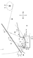
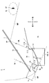
- the virtual image display device according to the first embodiment of the present disclosure is used in a vehicle 1 and is a head-up display device (hereinafter referred to as HUD) accommodated in an instrument panel 2 of the vehicle 1.
- the device is abbreviated to 100).
- the vehicle 1 is not limited to a car as in the present embodiment, but can be broadly understood to include a vehicle such as an aircraft, a ship, a housing that does not move, or the like, as well as a rail car.
- the HUD device 100 projects an image toward the projection unit 7 a set on the front windshield 7 of the vehicle 1.
- the HUD device 100 displays a virtual image so that the image can be viewed visually by the occupant of the vehicle 1 as a viewer. That is, the display light of the image reflected by the projection unit 7a reaches the eye point EP located in the visible area in the passenger sitting in the seat inside the vehicle 1, and the passenger makes a virtual image VRI of the display light. To perceive.
- Examples of various information displayed as a virtual image as an image include information indicating a vehicle state such as a vehicle speed and a remaining amount of fuel, or navigation information such as visibility auxiliary information and road information.
- the front windshield 7 of the vehicle 1 is formed of, for example, glass or synthetic resin in a translucent plate shape.
- the front windshield 7 is disposed to face the upper surface 2a of the instrument panel 2 facing upward, and is inclined, for example, to be separated from the upper surface 2a toward the rear.
- the front windshield 7 forms a projecting portion 7a on which an image is projected in a smooth concave shape or a planar shape.
- the projection unit 7 a may not be provided on the front windshield 7.
- a combiner that is separate from the vehicle 1 may be installed near the front windshield 7 in the vehicle 1, and the projector 7a may be provided in the combiner.
- the visual recognition area is a spatial area where the virtual image VRI displayed by the HUD device 100 can be visually recognized so as to satisfy a predetermined standard, and is also referred to as an eye box.
- the visual recognition area is typically set to overlap with the eyelid EL set in the vehicle 1.
- the eye lip EL is set in an elliptical shape based on an eye range that statistically represents the distribution of the eye position of the driver as the occupant of the vehicle 1 (for details, see JIS D 0021: 1998).
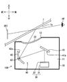
- the HUD device 100 includes a case 10, an opening cover 20, a display 30, a light guide 40, and the like.
- the case 10 is in the form of a hollow box made of, for example, a synthetic resin or metal, and is installed in the instrument panel 2 of the vehicle 1.
- the case 10 has a housing portion 11 configured to house the display 30 and the light guide portion 40, and a case opening 12 opened at the upper side facing the projection portion 7a.
- the entire area of the case opening 12 is closed by an opening cover 20 capable of transmitting display light.
- an instrument panel opening 2 b is opened in the upper surface portion 2 a of the instrument panel 2 of the vehicle 1 at a position corresponding to the case opening 12.
- the display 30 of the present embodiment is a liquid crystal display as shown in FIG.
- the display 30 has a backlight 31 and a liquid crystal panel 32, and is configured by housing them in a box-shaped casing having a light shielding property, for example.
- the display 30 transmits and illuminates the display screen of the liquid crystal panel 32 with the backlight 31 to display an image on the display screen, and emits display light contributing to the display of the virtual image VRI toward the light guide 40. It is supposed to be.
- the liquid crystal panel 32 of the present embodiment is a liquid crystal panel using thin film transistors (TFTs), and is an active matrix liquid crystal panel formed of, for example, a plurality of liquid crystal pixels arranged in a two-dimensional direction. It is.
- the liquid crystal panel 32 can control the transmittance of light of each liquid crystal pixel by the incidence of light from the backlight 31, and can form an image by display light emitted from the display screen. More adjacent liquid crystal pixels are provided with color filters of different colors (for example, red, green and blue), and various colors are realized by combining these.
- the display light emitted from the display 30 is linearly polarized.
- liquid crystal display an organic EL display, a display of a laser scanner system, or various displays of a DLP (Digital Light Processing (registered trademark)) system or the like can be adopted as the display 30.
- DLP Digital Light Processing (registered trademark)
- a plurality of displays 30 may be provided.
- the light guide unit 40 guides the display light incident from the display unit 30 to the projection unit 7a.
- the light guide 40 has, for example, a plane mirror 41 and a concave mirror 42.
- the plane mirror 41 is a reflecting mirror in which a reflecting surface 41 a is formed by depositing aluminum or the like on the surface of a base material made of a synthetic resin or glass.
- the reflecting surface 41a of the plane mirror 41 is formed in a smooth plane shape.
- the display light that has entered the flat mirror 41 from the display 30 is reflected by the reflective surface 41 a toward the concave mirror 42.
- the concave mirror 42 is a reflecting mirror in which a reflecting surface 42 a is formed by depositing aluminum or the like on the surface of a base material made of synthetic resin or glass.
- the reflecting surface 42 a of the concave mirror 42 is formed in a smooth concave shape by curving in a concave shape.
- the display light that has entered the concave mirror 42 is reflected by the reflecting surface 42 a toward the projection unit 7 a and, at the same time, is subjected to a magnifying action that magnifies the virtual image VRI.
- the concave mirror 42 is rotatable around a rotating shaft 43 extending in the left-right direction, so that the vertical position at which the virtual image VRI is displayed can be adjusted.
- the display light reflected by the reflection surface 42 a of the concave mirror 42 in this way is transmitted through the opening cover 20 provided in the case opening 12 and emitted from the inside of the case to the outside of the case to the projection unit 7 a located outside the case. It will be incident.
- the display light reflected by the projection unit 7a reaches the eyes of the occupant, the occupant can visually recognize the virtual image VRI.
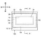
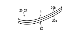
- the opening cover 20 has a rectangular outer shape and is formed in a flexible sheet shape.
- the cover surfaces 21 and 22 on both sides of the opening cover 20 are formed in a mirror-like shape with reduced roughness.
- the opening cover 20 of the present embodiment includes a light transmitting substrate layer 20a and a polarizing layer 20b formed in a stacked state with respect to the light transmitting substrate layer 20a.
- the polarizing layer 20 b is a polarizing element realized by a polarizing film or the like formed in a film shape.
- the polarizing layer 20b is formed, for example, by adding iodine to polyvinyl alcohol, and has a transmission axis and a light shielding axis (in particular, an absorption axis in the present embodiment) substantially orthogonal to each other depending on the orientation direction of iodine molecules.
- the polarizing layer 20b transmits the polarized light along the transmission axis at the maximum transmittance, and absorbs the polarized light along the absorption axis at the maximum absorptivity.
- the absorption axis is set to intersect the polarization direction of the display light emitted from the display 30.
- the transmission axis is set along the polarization direction of the display light.
- the opening cover 20 has a holding portion 23 and a cover portion 24.
- the holding portion 23 is provided on the outer peripheral portion of the opening cover 20 and is held by the case 10 as a holding member for holding the opening cover 20.
- a rectangular frame-shaped adhesive sheet 50 is attached to the case side.
- the adhesive sheet 50 has adhesiveness on both sides.
- the adhesive sheet 50 connects the holding portion 23 and the case edge 13 bordering the case opening 12 in the case 10 in a close contact state over the entire circumference.
- the cover portion 24 is configured to be surrounded by the holding portion 23 and to cover the entire case opening 12.
- the cover portion 24 is curved along the case edge 13 by the holding portion 23 being in close contact with the case edge 13.
- the case edge 13 has four sides 13a to 13d in accordance with the outer shape of the opening cover 20.
- the front side 13 a extends linearly in the left-right direction in front of the case opening 12.
- the rear side 13 b extends linearly in the left-right direction at the rear of the case opening 12.
- the front side 13a and the rear side 13b are disposed substantially parallel to each other. In the present embodiment, the front side 13a and the rear side 13b are located at substantially the same height in the vertical direction.
- the left side 13c and the right side 13d are formed in substantially the same shape to form a pair.
- the left side 13 c extends in the front-rear direction in the left with respect to the case opening 12, thereby connecting the front side 13 a and the rear side 13 b.
- the right side 13 d extends in the front-rear direction on the right side of the case opening 12 to connect the front side 13 a and the rear side 13 b.
- the left side 13c and the right side 13d are disposed substantially parallel to each other. In the present embodiment, the left side 13 c and the right side 13 d are located at substantially the same height in the vertical direction.
- the left side 13c and the right side 13d are curved along a parabola so as to be concave toward the space side where the display light is incident on both sides separated by the case opening 12 or the instrument panel opening 2b. It has become a parabola curved side.
- the side on which the display light is incident can also be referred to as the incident side of the display light, the inside of the case, the opposite side to the projection unit 7 a or the lower side of the vehicle 1.
- the cover 24 of the opening cover 20 disposed along the left side 13c and the right side 13d as the parabolic curved side also has a case opening 12 or an instrument panel in a cross section CS along the longitudinal and vertical directions of the vehicle 1 It curves along a parabola so that it may be dented to the incident side of a display light among the both sides separated by the opening 2b.
- the opening cover 20 is curved in a parabolic cylinder shape in which the extension direction of the cylinder is along the left-right direction.
- the cover surface 21 facing the outer side of the case, that is, the upper side has a reflection surface that can reflect external light such as sunlight which is transmitted through the front windshield 7 from the outside of the vehicle 1 and enters. It has a parabolic cylindrical surface.
- a bezel wall 3 of the vehicle 1 is formed around the cover surface 21.
- the bezel wall 3 is formed in the shape of an upright wall covering the entire circumference so as to surround both the openings 2 b and 12.
- the bezel wall 3 is disposed to be in contact with the outermost periphery of the opening cover 20 by filling the gap, and the display light emission side (i.e., the upper side) of both sides separated from the opening cover 20 by the case opening 12 or the instrument panel opening 2b.
- the wall surface of the bezel wall 3 has a light shielding property by being formed in dark color (for example, black) so as to suppress reflection of external light and more preferably absorb external light.
- the bezel wall 3 has a front bezel wall 4 positioned forward with respect to the openings 2 b and 12, and a rear bezel wall 5 positioned rearward with respect to the openings 2 b and 12.
- the front bezel wall 4 is slightly inclined to be positioned rearward as it goes upward, and in a portion in contact with the opening cover 20, the front bezel wall 4 and the outermost periphery of the opening cover 20 form an acute angle ⁇ It is arranged in a way.
- the rear bezel wall 5 is slightly inclined so as to be positioned rearward as it goes upward, and in a portion in contact with the opening cover 20, the rear bezel wall 5 and the outermost periphery of the opening cover 20 have an obtuse angle It is arranged to make ⁇ .
- the apex Vp of the parabola forming the opening cover 20 of the present embodiment is set to be eccentric forward with respect to the center of the opening cover 20.
- the apex Vp of the parabola appears in the aperture cover 20 without being offset.
- the symmetry axis Ap of the parabola is inclined with respect to the horizontal plane to fall back.
- the locus of a virtual ray IMR (see the broken line in FIG. 1) assumed as external light is considered.
- This light beam IMR enters the front windshield 7 of the vehicle 1 obliquely from the front, passes through the front windshield 7, is reflected by the cover surface 21, and passes through the upper end 5a of the rear bezel wall 5 (or It is a ray that passes through so that it is reflected, then is reflected at the reflection position RP of the projection part 7a of the front windshield 7, and passes through the eyelid EL from below, and defines the locus of the ray IMR as a virtual optical path.
- a straight line connecting the upper end 5a of the rear bezel wall 5 and the reflection position RP of the projection unit 7a is defined as a virtual line IML.
- eyedrop EL it is preferable to use an eyedrop of 90th percentile or more and 99th percentile or less such as 90th percentile eyedrops, 95th percentile eyedrops, 99th percentile eyedrops, or the like.
- the imaginary line IML normally extends in a direction going backward as going upward, and the direction of the symmetry axis Ap of the parabola of the opening cover 20 is set along the direction of the imaginary line IML. More preferably, the symmetry axis Ap of the parabola should be set substantially parallel to the imaginary line IML.
- the parabola has a property of collecting light rays incident in parallel to the symmetry axis Ap at a certain point (focus Fp). According to this property, by setting the symmetry axis Ap substantially parallel to the imaginary line IML, the ray IMR along the imaginary line IML passes through the focal point Fp of the parabola. By shielding the lower side of the focal point Fp with a light shielding member such as the front bezel wall 4 or the like, it is possible to suppress external light from entering the eyelid EL after being reflected by the cover surface 21.
- a light shielding member such as the front bezel wall 4 or the like
- the height of the focal point Fp along the symmetry axis Ap is given by a / 4 using the second-order coefficient a of the parabola.
- the height h of the front bezel wall 4 is defined as h, light passing below the focal point Fp can be blocked by the front bezel wall 4 if the conditional expression of h> a / 4 is satisfied. It can be expected to have the effect of suppressing entry into the inside. That is, it is desirable to set the degree of opening of the parabola so that a ⁇ 4 ⁇ h holds.
- the height h of the front bezel wall 4 in this embodiment is a dimension along the vertical direction with respect to the tangent plane IMP from the virtual tangent plane IMP in contact with the apex Vp of the parabola to the upper end 4a of the front bezel wall 4 It is defined.
- the position of the focal point Fp of the parabola is located on the space behind the front bezel wall 4.
- the opening cover 20 for closing the case opening 12 is curved along a parabola so as to be recessed toward the incident side of the display light. Due to this curved form, a part of the external light incident on the aperture cover 20 is reflected and condensed at the same time using the property of a parabola. That is, since the spread of the external light reflected by the opening cover 20 is suppressed, the probability of reaching the eyes of the occupant can be reduced. Therefore, it is also possible to reduce the probability that it becomes difficult for the occupant to visually recognize the virtual image VRI when the occupant feels that the reflected light is dazzling.
- the opening cover 20 is curved in a parabolic cylinder shape.
- this curved form generation of unintended wrinkles and distortion for curving the opening cover 20 can be suppressed, and external light which is shifted in the non-parabolic direction of the parabolic cylinder (for example, the left and right direction of the vehicle)
- external light which is shifted in the non-parabolic direction of the parabolic cylinder (for example, the left and right direction of the vehicle)
- the case opening 12 is disposed in the instrument panel 2 of the vehicle 1 so as to be surrounded by the bezel wall 3 in the upright wall shape.
- Such a bezel wall 3 can block an optical path that reaches the eyes of the occupant after the outside light enters the opening cover 20, so that the occupant feels the reflected light dazzling, and the occupant can make a virtual image VRI.
- the suppression effect of becoming difficult to visually recognize can be heightened.
- the parabola is configured such that a ⁇ 4 ⁇ h is established. Therefore, since the light passing below the focal point Fp of the parabola can be blocked by the front bezel wall 4, the blocking action of blocking the light path reaching the eyes of the occupant by the front bezel wall 4 becomes even higher.
- the symmetry axis Ap of the parabola is substantially parallel to the imaginary line IML.
- external light that is reflected by the aperture cover 20 and reaches the lower end of the eyelid EL just passes through the focal point Fp, so if light below the focal point Fp is blocked by the bezel wall 3, it is efficient It is possible to suppress the entrance of external light to eye Rip EL. Therefore, the probability that the outside light reaches the eyes of the occupant is further reduced, and the suppression effect of making it difficult for the occupant to visually recognize the virtual image VRI is remarkable.
- the aperture cover 20 has a polarizing layer 20b as a polarizing element.
- the outside light enters the inside of the case and is converted to heat, thereby reducing the life of the HUD device 100 and suppressing the occupant from looking into the inside of the case. it can.
- the left side 13 c and the right side 13 d as parabola curved sides are provided at the case edge 13 which borders the case opening 12, whereby the case opening 12 is covered by the opening cover 20.
- the opening cover 20 can be easily curved along a parabola by holding the opening cover 20 along the sides 13 c and 13 d when the opening cover 20 is closed. Therefore, the HUD device 100 with high visibility of the virtual image VRI can be easily provided.
- the cover portion 24 is curved along a parabola so as to be recessed toward the incident side of the display light. Due to this curvature, a part of the external light incident on the aperture cover 20 is reflected and condensed at the same time using the property of a parabola. That is, since the spread of the external light reflected by the opening cover 20 is suppressed, the probability of reaching the eyes of the occupant can be reduced. Therefore, it is also possible to reduce the probability that it becomes difficult for the occupant to visually recognize the virtual image VRI when the occupant feels that the reflected light is dazzling.
- the second embodiment is a modification of the first embodiment.
- the second embodiment will be described focusing on differences from the first embodiment.
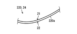
- the aperture cover 220 of the second embodiment has a polycarbonate sheet 220 a that causes a phase difference in display light.
- the polycarbonate sheet 220a is formed to have flexibility by rolling a polycarbonate resin with a plurality of rollers.
- the polycarbonate sheet 220 a is a birefringent material sheet in which the refractive index along the rolling direction and the refractive index along the orthogonal direction orthogonal to the rolling direction are different from each other. Due to the difference in refractive index, the polycarbonate sheet 220a causes a phase difference between the polarization component in the rolling direction and the polarization component in the orthogonal direction in the display light.
- the aperture cover 220 includes the polycarbonate sheet 220 a that causes the display light to have a phase difference.
- the polycarbonate sheet 220a optimizes the polarization state of the display light. As a result, it is possible to increase the reflectance of the display light in the projection unit 7 a or to increase the transmittance of the display light in the polarized sunglasses worn by the occupant. Therefore, the visibility of the virtual image VRI is enhanced.
- the polycarbonate sheet 220a changes the polarization direction of the display light or converts the linearly polarized display light into elliptically polarized light. It is possible to impart polarization components in the vertical direction of the vehicle 1 to the display light, and to increase the transmittance of the display light in the polarization sunglasses worn by the occupant.
- the focal point Fp of the parabola may be positioned so as to overlap on the wall surface of the front bezel wall 4.
- the front bezel wall 4 can be configured to be lower, and the design freedom of the vehicle 1 can be enhanced.
- the position of the focal point Fp of the parabola may be located forward of the wall surface of the front bezel wall 4.
- the apex Vp of the parabola is offset and does not appear in the aperture cover 20. Therefore, since the focal point Fp of the parabola is located further downward, it is easy to establish h> a / 4 even if the front bezel wall 4 itself is miniaturized. Therefore, the front bezel wall 4 can be configured to be lower, and the design freedom of the vehicle 1 can be enhanced.
- a hard coat film, an antireflection film, or the like may be formed on the cover surfaces 21 and 22 of the opening cover 20.
- the opening cover 20 may be held by the case 10 by a method other than the adhesive sheet, for example, locking by a claw, locking by screwing, locking by a pin, or the like.
- the holding member for holding the opening cover 20 is not limited to the case 10, and may be, for example, the bezel wall 3.
- the light transmitting substrate layer 20a in the opening cover 20 of the first embodiment may be replaced with the polycarbonate sheet 220a of the second embodiment.
- the virtual image display device displays the virtual image VRI in a visible manner by using the reflection of the display light by the projection unit 7a.
- the virtual image display device includes a display 30 that emits display light.
- the virtual image display device is a case for housing a display, and further includes a case 10 having an opening 12 for emitting display light to the outside of the case so that the display light is projected on a projection unit located outside the case.
- the virtual image display device further includes an opening cover 20, 220 that closes the opening.
- the opening cover is curved along a parabola so as to be concave toward the display light incident side on both sides separated by the opening.
- the opening cover closing the opening of the case is curved along a parabola so as to be recessed toward the incident side of the display light. Due to this curved form, a part of the external light incident on the aperture cover is reflected and condensed at the same time using the property of the parabola. That is, since the spread of external light reflected by the aperture cover is suppressed, the probability of reaching the eye of the viewer can be reduced. Therefore, when the viewer feels that the reflected light is dazzling, it is possible to reduce the probability that the viewer does not easily recognize the virtual image.
- the case for the virtual image display device is used for the virtual image display device 100 that displays the virtual image VRI in a viewable manner by using the reflection of the display light by the projection unit 7a.
- the virtual image display case includes an accommodating portion 11 configured to accommodate the display 30 that emits display light.
- the case for a virtual image display device further includes an opening 12 for emitting display light to the outside of the case so that the display light is projected onto the projection unit 7a located outside the case.
- the edge 13 for bordering the opening has parabolic curved sides 13c and 13d curved along a parabola so as to be recessed toward the display light incident side on both sides separated by the opening.
- the parabolic curved side is provided at the edge bordering the opening, so that the opening cover is held along the parabolic curved side when the opening is closed by the opening cover. This allows the opening cover to be easily curved along a parabola. Therefore, a virtual image display device with high visibility of the virtual image can be easily provided.
- the aperture cover disclosed herein is used for the virtual image display device 100 that displays the virtual image VRI in a viewable manner by using the reflection of the display light at the projection unit 7a, and the display light is projected on the projection unit
- the openings 2 b and 12 for emitting display light to the projection unit side are closed.
- the opening cover has a holding portion 23 held by the holding member 10.
- the opening cover further includes a cover portion 24 which is curved along a parabola so as to be recessed on the opposite side to the projection of the two sides separated by the opening.
- the cover portion is curved along a parabola so as to be recessed toward the display light incident side. Due to this curved form, a part of the external light incident on the aperture cover is reflected and condensed at the same time using the property of the parabola. That is, since the spread of external light reflected by the aperture cover is suppressed, the probability of reaching the eye of the viewer can be reduced. Therefore, when the viewer feels that the reflected light is dazzling, it is possible to reduce the probability that the viewer does not easily recognize the virtual image.
Landscapes
- Engineering & Computer Science (AREA)
- Chemical & Material Sciences (AREA)
- Combustion & Propulsion (AREA)
- Transportation (AREA)
- Mechanical Engineering (AREA)
- Physics & Mathematics (AREA)
- General Physics & Mathematics (AREA)
- Optics & Photonics (AREA)
- Instrument Panels (AREA)
Abstract
A HUD device (100) of the present invention uses the reflection of display light on a projection part (7a) to visibly display a virtual image. The HUD device (100) comprises: a display device for emitting display light; a case (10) for accommodating the display device, the case comprising an opening (12) for emitting the display light to the exterior of the case so that the display light is projected onto a projection part (7a), which is positioned to the exterior of the case; and an opening cover (20) for closing off the opening (12). The opening cover (20) is curved along a parabola so as to recede toward the side, among the two sides partitioned by the opening (12), on which the display light is incident.
Description
本出願は、2017年12月1日に出願された日本出願番号2017-231876号に基づくもので、ここにその記載内容を援用する。
This application is based on Japanese Patent Application No. 2017-231876 filed on Dec. 1, 2017, the contents of which are incorporated herein by reference.
本開示は、虚像を視認可能に表示する虚像表示装置に関する。
The present disclosure relates to a virtual image display device that visibly displays a virtual image.
従来、虚像を視認可能に表示する虚像表示装置が知られている。特許文献1に開示の装置は、表示器、ケース、及び開口カバーを備えている。表示器は、表示光を発する。ケースは、表示器を収容するケースであって、表示光がケース外部に位置する投影部に投影されるように、当該表示光をケース外部に射出する開口を有する。開口カバーは、開口を塞いでいる。
BACKGROUND Conventionally, a virtual image display device that displays a virtual image in a visible manner is known. The device disclosed in Patent Document 1 includes a display, a case, and an opening cover. The display emits display light. The case is a case that accommodates the display, and has an opening that emits the display light to the outside of the case so that the display light is projected to a projection unit located outside the case. The opening cover blocks the opening.
特許文献1の開口カバーは、ケース外部からケース内部へ入射しようとする太陽光等の外光の一部を吸収するようになっている。しかしその一方で、特許文献1の開口カバーは、平板状に形成されている。このような平板状の開口カバーに入射する外光の一部がその表面で反射され、この反射光が視認者の目に入射し得る。こうした反射光が視認者の目に多く入射すると、視認者が眩しく感じるため、虚像を視認し難い状態となってしまう。
The opening cover of Patent Document 1 is adapted to absorb a part of external light such as sunlight which is to be incident from the outside of the case into the inside of the case. However, on the other hand, the opening cover of Patent Document 1 is formed in a flat plate shape. A part of the external light incident on such a flat aperture cover may be reflected on the surface, and this reflected light may be incident on the eye of the viewer. When such reflected light is incident on the eyes of the viewer in a large amount, the viewer feels dazzling, which makes it difficult to view a virtual image.
開示されるひとつの目的は、虚像の視認性が高い虚像表示装置並びにこれに用いられるケース及び開口カバーを提供することにある。
One object disclosed is to provide a virtual image display device with high visibility of a virtual image and a case and an aperture cover used therefor.
本開示の第一の態様における虚像表示装置は、投影部での表示光の反射を用いて、虚像を視認可能に表示する。虚像表示装置は、前記表示光を発する表示器を備える。虚像表示装置は、前記表示器を収容するケースであって、前記表示光がケース外部に位置する前記投影部に投影されるように、前記表示光をケース外部へと射出する開口を有するケースを、更に備える。虚像表示装置は、前記開口を塞ぐ開口カバーを、更に備える。前記開口カバーは、前記開口により隔てられた両側のうち前記表示光の入射側へ凹むように、放物線に沿って湾曲している。
The virtual image display device according to the first aspect of the present disclosure uses the reflection of display light at the projection unit to visually display a virtual image. The virtual image display apparatus includes a display that emits the display light. The virtual image display device is a case that accommodates the display, and has a case that emits the display light to the outside of the case so that the display light is projected onto the projection unit located outside the case. , Further provided. The virtual image display device further includes an opening cover that closes the opening. The opening cover is curved along a parabola so as to be concave toward the display light incident side on the both sides separated by the opening.
本開示についての上記目的およびその他の目的、特徴や利点は、添付の図面を参照しながら下記の詳細な記述により、より明確になる。その図面は、
第1実施形態のHUD装置の車両への搭載状態を示す断面図である。
第1実施形態のHUD装置の表示部及び導光部の概略構成を示す断面図である。
第1実施形態のHUD装置の上面図である。
第1実施形態の開口カバーの構成を説明するための断面図である。
第2実施形態における図4に対応する図である。
変形例1における図1に対応する図である。
変形例2における図1に対応する図である。
The above object and other objects, features and advantages of the present disclosure will become more apparent from the following detailed description with reference to the attached drawings. The drawing is
It is sectional drawing which shows the mounting state to the vehicle of the HUD apparatus of 1st Embodiment. It is sectional drawing which shows schematic structure of the display part of the HUD apparatus of 1st Embodiment, and a light guide. It is a top view of HUD device of a 1st embodiment. It is sectional drawing for demonstrating the structure of the opening cover of 1st Embodiment. It is a figure corresponding to FIG. 4 in 2nd Embodiment. It is a figure corresponding to FIG. 1 in the modification 1. FIG. It is a figure corresponding to FIG. 1 in the modification 2. FIG.
以下、複数の実施形態を図面に基づいて説明する。なお、各実施形態において対応する構成要素には同一の符号を付すことにより、重複する説明を省略する場合がある。各実施形態において構成の一部分のみを説明している場合、当該構成の他の部分については、先行して説明した他の実施形態の構成を適用することができる。また、各実施形態の説明において明示している構成の組み合わせばかりではなく、特に組み合わせに支障が生じなければ、明示していなくても複数の実施形態の構成同士を部分的に組み合せることができる。
Hereinafter, a plurality of embodiments will be described based on the drawings. In addition, the overlapping description may be abbreviate | omitted by attaching the same code | symbol to the corresponding component in each embodiment. When only a part of the configuration is described in each embodiment, the configuration of the other embodiments described above can be applied to other parts of the configuration. In addition to the combinations of the configurations explicitly described in the description of each embodiment, the configurations of the plurality of embodiments can be partially combined with each other even if they are not explicitly specified unless any problem occurs in the combination. .
(第1実施形態)
図1,2に示すように、本開示の第1実施形態による虚像表示装置は、車両1に用いられ、当該車両1のインストルメントパネル2内に収容されているヘッドアップディスプレイ装置(以下、HUD装置を略称とする)100である。ここで車両1とは、本実施形態のような自動車だけに限られず、鉄道車両の他、航空機、船舶、移動しない筐体等の乗り物を含むように広義に解される。HUD装置100は、車両1のフロントウインドシールド7に設定された投影部7aへ向けて画像を投影する。これによりHUD装置100は、画像を視認者としての車両1の乗員により視認可能に虚像表示する。すなわち、投影部7aにて反射される画像の表示光が、車両1の室内の座席に着座する乗員において、視認領域内に位置するアイポイントEPに到達し、当該乗員が当該表示光を虚像VRIとして知覚する。画像として虚像表示される各種情報としては、例えば車速、燃料残量等の車両の状態を示す情報、又は視界補助情報、道路情報等のナビゲーション情報等が挙げられる。 First Embodiment
As shown in FIGS. 1 and 2, the virtual image display device according to the first embodiment of the present disclosure is used in avehicle 1 and is a head-up display device (hereinafter referred to as HUD) accommodated in an instrument panel 2 of the vehicle 1. The device is abbreviated to 100). Here, the vehicle 1 is not limited to a car as in the present embodiment, but can be broadly understood to include a vehicle such as an aircraft, a ship, a housing that does not move, or the like, as well as a rail car. The HUD device 100 projects an image toward the projection unit 7 a set on the front windshield 7 of the vehicle 1. As a result, the HUD device 100 displays a virtual image so that the image can be viewed visually by the occupant of the vehicle 1 as a viewer. That is, the display light of the image reflected by the projection unit 7a reaches the eye point EP located in the visible area in the passenger sitting in the seat inside the vehicle 1, and the passenger makes a virtual image VRI of the display light. To perceive. Examples of various information displayed as a virtual image as an image include information indicating a vehicle state such as a vehicle speed and a remaining amount of fuel, or navigation information such as visibility auxiliary information and road information.
図1,2に示すように、本開示の第1実施形態による虚像表示装置は、車両1に用いられ、当該車両1のインストルメントパネル2内に収容されているヘッドアップディスプレイ装置(以下、HUD装置を略称とする)100である。ここで車両1とは、本実施形態のような自動車だけに限られず、鉄道車両の他、航空機、船舶、移動しない筐体等の乗り物を含むように広義に解される。HUD装置100は、車両1のフロントウインドシールド7に設定された投影部7aへ向けて画像を投影する。これによりHUD装置100は、画像を視認者としての車両1の乗員により視認可能に虚像表示する。すなわち、投影部7aにて反射される画像の表示光が、車両1の室内の座席に着座する乗員において、視認領域内に位置するアイポイントEPに到達し、当該乗員が当該表示光を虚像VRIとして知覚する。画像として虚像表示される各種情報としては、例えば車速、燃料残量等の車両の状態を示す情報、又は視界補助情報、道路情報等のナビゲーション情報等が挙げられる。 First Embodiment
As shown in FIGS. 1 and 2, the virtual image display device according to the first embodiment of the present disclosure is used in a
以下において、特に断り書きが無い限り、前後、上下、左右等の方向は、水平面上の車両を基準として表記される。
In the following, unless stated otherwise, directions such as front and rear, up and down, left and right, etc. are written based on a vehicle on a horizontal surface.
車両1のフロントウインドシールド7は、例えばガラスないしは合成樹脂により透光性の板状に形成されている。フロントウインドシールド7は、インストルメントパネル2において上方を向く上面部2aと対向するように配置され、例えば後方へ向かう程上面部2aとは離間するように傾斜して配置されている。フロントウインドシールド7は、画像が投影される投影部7aを、滑らかな凹面状又は平面状に形成している。なお、投影部7aは、フロントウインドシールド7に設けられていなくてもよい。例えば、車両1と別体となっているコンバイナを車両1内のフロントウインドシールド7付近に設置して、当該コンバイナに投影部7aが設けられていてもよい。
The front windshield 7 of the vehicle 1 is formed of, for example, glass or synthetic resin in a translucent plate shape. The front windshield 7 is disposed to face the upper surface 2a of the instrument panel 2 facing upward, and is inclined, for example, to be separated from the upper surface 2a toward the rear. The front windshield 7 forms a projecting portion 7a on which an image is projected in a smooth concave shape or a planar shape. The projection unit 7 a may not be provided on the front windshield 7. For example, a combiner that is separate from the vehicle 1 may be installed near the front windshield 7 in the vehicle 1, and the projector 7a may be provided in the combiner.
視認領域は、HUD装置100により表示される虚像VRIが所定の規格を満たすように視認可能となる空間領域であって、アイボックスとも称される。視認領域は、典型的には、車両1に設定されたアイリプスELと重なるように設定される。アイリプスELは、車両1の乗員としての運転者の目の位置の分布を統計的に表したアイレンジに基づいて、楕円体状に設定されている(詳細は、JISD0021:1998参照)。
The visual recognition area is a spatial area where the virtual image VRI displayed by the HUD device 100 can be visually recognized so as to satisfy a predetermined standard, and is also referred to as an eye box. The visual recognition area is typically set to overlap with the eyelid EL set in the vehicle 1. The eye lip EL is set in an elliptical shape based on an eye range that statistically represents the distribution of the eye position of the driver as the occupant of the vehicle 1 (for details, see JIS D 0021: 1998).
このようなHUD装置100の具体的構成を、以下に説明する。HUD装置100は、図2に示すように、ケース10、開口カバー20、表示器30及び導光部40等により構成されている。
The specific configuration of such a HUD device 100 will be described below. As shown in FIG. 2, the HUD device 100 includes a case 10, an opening cover 20, a display 30, a light guide 40, and the like.
ケース10は、例えば合成樹脂ないしは金属により、中空箱状を呈しており、車両1のインストルメントパネル2内に設置されている。ケース10は、表示器30及び導光部40を収容するように構成された収容部11と、投影部7aと対向する上方において開口するケース開口12とを、有している。図3にも示すように、ケース開口12の全域は、表示光を透過可能な開口カバー20により塞がれている。また、車両1のインストルメントパネル2の上面部2aにおいて、ケース開口12と対応する箇所には、インパネ開口2bが開口している。
The case 10 is in the form of a hollow box made of, for example, a synthetic resin or metal, and is installed in the instrument panel 2 of the vehicle 1. The case 10 has a housing portion 11 configured to house the display 30 and the light guide portion 40, and a case opening 12 opened at the upper side facing the projection portion 7a. As also shown in FIG. 3, the entire area of the case opening 12 is closed by an opening cover 20 capable of transmitting display light. Further, an instrument panel opening 2 b is opened in the upper surface portion 2 a of the instrument panel 2 of the vehicle 1 at a position corresponding to the case opening 12.
本実施形態の表示器30は、図2に示すように、液晶表示器となっている。表示器30は、バックライト31及び液晶パネル32を有し、例えば遮光性を有する箱状のケーシングにこれらを収容して構成されている。表示器30は、バックライト31により液晶パネル32の表示画面を透過照明することで、当該表示画面に画像を表示し、虚像VRIの表示に寄与する表示光を導光部40側へ向けて発するようになっている。
The display 30 of the present embodiment is a liquid crystal display as shown in FIG. The display 30 has a backlight 31 and a liquid crystal panel 32, and is configured by housing them in a box-shaped casing having a light shielding property, for example. The display 30 transmits and illuminates the display screen of the liquid crystal panel 32 with the backlight 31 to display an image on the display screen, and emits display light contributing to the display of the virtual image VRI toward the light guide 40. It is supposed to be.
ここで本実施形態の液晶パネル32は、薄膜トランジスタ(Thin Film Transistor、TFT)を用いた液晶パネルであって、例えば二次元方向に配列された複数の液晶画素から形成されたアクティブマトリクス型の液晶パネルである。液晶パネル32は、バックライト31からの光の入射により、液晶画素毎の当該光の透過率を制御可能となっており、表示画面から射出される表示光によって画像を形成することができる。より隣り合う液晶画素には、互いに異なる色(例えば、赤色、緑色、及び青色)のカラーフィルタが設けられており、これらの組み合わせにより様々な色が実現されるようになっている。表示器30から発せられる表示光は、直線偏光となっている。
Here, the liquid crystal panel 32 of the present embodiment is a liquid crystal panel using thin film transistors (TFTs), and is an active matrix liquid crystal panel formed of, for example, a plurality of liquid crystal pixels arranged in a two-dimensional direction. It is. The liquid crystal panel 32 can control the transmittance of light of each liquid crystal pixel by the incidence of light from the backlight 31, and can form an image by display light emitted from the display screen. More adjacent liquid crystal pixels are provided with color filters of different colors (for example, red, green and blue), and various colors are realized by combining these. The display light emitted from the display 30 is linearly polarized.
なお、表示器30には、液晶表示器に代えて、有機ELディスプレイ、レーザスキャナ方式の表示器、又はDLP(Digital Light Processing;登録商標)方式の各種の表示器等を採用することができる。また、表示器30を複数設けるようにしてもよい。
Note that, instead of the liquid crystal display, an organic EL display, a display of a laser scanner system, or various displays of a DLP (Digital Light Processing (registered trademark)) system or the like can be adopted as the display 30. In addition, a plurality of displays 30 may be provided.
導光部40は、表示器30から入射した表示光を、投影部7aへと導光する。導光部40は、例えば平面鏡41及び凹面鏡42を有している。平面鏡41は、合成樹脂ないしはガラス等からなる基材の表面に、アルミニウムを蒸着されること等により反射面41aを形成した反射鏡である。平面鏡41の反射面41aは、滑らかな平面状に形成されている。表示器30から平面鏡41に入射した表示光は、反射面41aにより凹面鏡42へ向けて反射される。
The light guide unit 40 guides the display light incident from the display unit 30 to the projection unit 7a. The light guide 40 has, for example, a plane mirror 41 and a concave mirror 42. The plane mirror 41 is a reflecting mirror in which a reflecting surface 41 a is formed by depositing aluminum or the like on the surface of a base material made of a synthetic resin or glass. The reflecting surface 41a of the plane mirror 41 is formed in a smooth plane shape. The display light that has entered the flat mirror 41 from the display 30 is reflected by the reflective surface 41 a toward the concave mirror 42.
凹面鏡42は、合成樹脂ないしはガラス等からなる基材の表面に、アルミニウムを蒸着すること等により反射面42aを形成した反射鏡である。凹面鏡42の反射面42aは、凹状に湾曲することで、滑らかな凹面状に形成されている。凹面鏡42に入射した表示光は、反射面42aにより投影部7aへ向けて反射されると同時に、虚像VRIを拡大させる拡大作用を受ける。また、凹面鏡42は、左右方向に延びる回転軸43まわりに回動可能となっており、虚像VRIが表示される上下方向の位置を調整できるようになっている。
The concave mirror 42 is a reflecting mirror in which a reflecting surface 42 a is formed by depositing aluminum or the like on the surface of a base material made of synthetic resin or glass. The reflecting surface 42 a of the concave mirror 42 is formed in a smooth concave shape by curving in a concave shape. The display light that has entered the concave mirror 42 is reflected by the reflecting surface 42 a toward the projection unit 7 a and, at the same time, is subjected to a magnifying action that magnifies the virtual image VRI. In addition, the concave mirror 42 is rotatable around a rotating shaft 43 extending in the left-right direction, so that the vertical position at which the virtual image VRI is displayed can be adjusted.
こうして凹面鏡42の反射面42aに反射された表示光は、ケース開口12に設けられた開口カバー20を透過することで、ケース内部からケース外部へ射出され、ケース外部に位置する投影部7aへと入射する。投影部7aに反射された表示光が乗員の眼に到達することによって、当該乗員は虚像VRIを視認可能となる。
The display light reflected by the reflection surface 42 a of the concave mirror 42 in this way is transmitted through the opening cover 20 provided in the case opening 12 and emitted from the inside of the case to the outside of the case to the projection unit 7 a located outside the case. It will be incident. When the display light reflected by the projection unit 7a reaches the eyes of the occupant, the occupant can visually recognize the virtual image VRI.
ここで、開口カバー20とその周囲の構成についてより詳細に説明する。開口カバー20は、図3に示すように、矩形状の外形をなし、可撓性を有するシート状に形成されている。開口カバー20を透過する表示光が拡散して乱されることを抑制するため、開口カバー20において両側のカバー面21,22は、粗さを低減した鏡面状に形成されている。本実施形態の開口カバー20は、図4に示すように、透光基板層20aと、透光基板層20aに対して積層状態に形成された偏光層20bを有している。
Here, the configuration of the opening cover 20 and the periphery thereof will be described in more detail. As shown in FIG. 3, the opening cover 20 has a rectangular outer shape and is formed in a flexible sheet shape. In order to suppress diffusion and disturbance of display light transmitted through the opening cover 20, the cover surfaces 21 and 22 on both sides of the opening cover 20 are formed in a mirror-like shape with reduced roughness. As shown in FIG. 4, the opening cover 20 of the present embodiment includes a light transmitting substrate layer 20a and a polarizing layer 20b formed in a stacked state with respect to the light transmitting substrate layer 20a.
偏光層20bは、フィルム状に形成された偏光フィルム等により実現されている偏光素子である。偏光層20bは、例えばポリビニルアルコールにヨウ素を添加して形成され、ヨウ素分子の配向方向によって透過軸と遮光軸(特に本実施形態では吸収軸)を互いに実質直交した状態で有している。偏光層20bは、透過軸に沿った偏光を最大の透過率にて透過させると共に、吸収軸に沿った偏光を最大の吸収率にて吸収する。ここで、吸収軸が表示器30から発せられた表示光の偏光方向とは交差するように設定される。好ましくは、透過軸が表示光の偏光方向に沿うように設定される。
The polarizing layer 20 b is a polarizing element realized by a polarizing film or the like formed in a film shape. The polarizing layer 20b is formed, for example, by adding iodine to polyvinyl alcohol, and has a transmission axis and a light shielding axis (in particular, an absorption axis in the present embodiment) substantially orthogonal to each other depending on the orientation direction of iodine molecules. The polarizing layer 20b transmits the polarized light along the transmission axis at the maximum transmittance, and absorbs the polarized light along the absorption axis at the maximum absorptivity. Here, the absorption axis is set to intersect the polarization direction of the display light emitted from the display 30. Preferably, the transmission axis is set along the polarization direction of the display light.
開口カバー20は、保持部23及びカバー部24を有している。保持部23は、開口カバー20の外周部に設けられ、当該開口カバー20を保持する保持部材としてのケース10に保持されている。例えば図3に示すように、保持部23において、ケース側には、矩形枠状の粘着シート50が貼り付けられている。粘着シート50は、両面に粘着性を有している。粘着シート50は、保持部23と、ケース10においてケース開口12を縁取っているケース縁部13とを、全周に亘って密着状態で接続している。
The opening cover 20 has a holding portion 23 and a cover portion 24. The holding portion 23 is provided on the outer peripheral portion of the opening cover 20 and is held by the case 10 as a holding member for holding the opening cover 20. For example, as shown in FIG. 3, in the holding unit 23, a rectangular frame-shaped adhesive sheet 50 is attached to the case side. The adhesive sheet 50 has adhesiveness on both sides. The adhesive sheet 50 connects the holding portion 23 and the case edge 13 bordering the case opening 12 in the case 10 in a close contact state over the entire circumference.
カバー部24は、保持部23に囲まれてケース開口12の全域を塞ぐように構成されている。カバー部24は、保持部23がケース縁部13と密着していることにより、当該ケース縁部13に沿うように湾曲している。
The cover portion 24 is configured to be surrounded by the holding portion 23 and to cover the entire case opening 12. The cover portion 24 is curved along the case edge 13 by the holding portion 23 being in close contact with the case edge 13.
ケース縁部13は、開口カバー20の外形に合わせて、4つの辺13a~dをなしている。前側辺13aは、ケース開口12に対する前方において左右方向に沿って直線的に延伸している。後側辺13bは、ケース開口12に対する後方において左右方向に沿って直線的に延伸している。前側辺13a及び後側辺13bは、互いに実質平行に配置されている。本実施形態では、前側辺13a及び後側辺13bは、上下方向において、略同じ高さに位置している。
The case edge 13 has four sides 13a to 13d in accordance with the outer shape of the opening cover 20. The front side 13 a extends linearly in the left-right direction in front of the case opening 12. The rear side 13 b extends linearly in the left-right direction at the rear of the case opening 12. The front side 13a and the rear side 13b are disposed substantially parallel to each other. In the present embodiment, the front side 13a and the rear side 13b are located at substantially the same height in the vertical direction.
左側辺13cと右側辺13dとは、実質同形状に形成されて対をなしている。左側辺13cは、ケース開口12に対する左方において前後方向に延伸していることで、前側辺13aと後側辺13bとを接続している。右側辺13dは、ケース開口12に対する右方において前後方向に延伸していることで、前側辺13aと後側辺13bとを接続している。左側辺13cと右側辺13dとは、互いに実質平行に配置されている。本実施形態では、左側辺13c及び右側辺13dは、上下方向において、略同じ高さに位置している。
The left side 13c and the right side 13d are formed in substantially the same shape to form a pair. The left side 13 c extends in the front-rear direction in the left with respect to the case opening 12, thereby connecting the front side 13 a and the rear side 13 b. The right side 13 d extends in the front-rear direction on the right side of the case opening 12 to connect the front side 13 a and the rear side 13 b. The left side 13c and the right side 13d are disposed substantially parallel to each other. In the present embodiment, the left side 13 c and the right side 13 d are located at substantially the same height in the vertical direction.
ここで図1に示すように、左側辺13c及び右側辺13dは、ケース開口12又はインパネ開口2bにより隔てられた両側のうち表示光が入射する空間側へ凹むように、放物線に沿って湾曲している放物湾曲辺となっている。ここで本実施形態において、表示光が入射する側とは、表示光の入射側、ケース内部側、投影部7aとは反対側又は車両1における下側とも換言できる。
Here, as shown in FIG. 1, the left side 13c and the right side 13d are curved along a parabola so as to be concave toward the space side where the display light is incident on both sides separated by the case opening 12 or the instrument panel opening 2b. It has become a parabola curved side. Here, in the present embodiment, the side on which the display light is incident can also be referred to as the incident side of the display light, the inside of the case, the opposite side to the projection unit 7 a or the lower side of the vehicle 1.
放物湾曲辺としての左側辺13c及び右側辺13dに沿って配置される開口カバー20の主にカバー部24も、車両1の前後方向及び上下方向に沿った断面CSにおいて、ケース開口12又はインパネ開口2bにより隔てられた両側のうち表示光の入射側へ凹むように、放物線に沿って湾曲している。
The cover 24 of the opening cover 20 disposed along the left side 13c and the right side 13d as the parabolic curved side also has a case opening 12 or an instrument panel in a cross section CS along the longitudinal and vertical directions of the vehicle 1 It curves along a parabola so that it may be dented to the incident side of a display light among the both sides separated by the opening 2b.
より詳細に開口カバー20は、筒の延伸方向が左右方向に沿った放物筒状に湾曲している。こうした開口カバー20において、ケース外部側、すなわち上側を向くカバー面21は、例えば車両1の外部からフロントウインドシールド7を透過して入射する太陽光等の外光を、反射し得る反射面を、放物筒面状に形成している。
In more detail, the opening cover 20 is curved in a parabolic cylinder shape in which the extension direction of the cylinder is along the left-right direction. In such an opening cover 20, the cover surface 21 facing the outer side of the case, that is, the upper side, has a reflection surface that can reflect external light such as sunlight which is transmitted through the front windshield 7 from the outside of the vehicle 1 and enters. It has a parabolic cylindrical surface.
カバー面21の周囲には、車両1のベゼル壁3が形成されている。ベゼル壁3は、両開口2b,12を囲むように、全周に亘る立壁状に形成されている。ベゼル壁3は、開口カバー20の最外周部と隙間を埋めて接するように配置され、開口カバー20から、ケース開口12又はインパネ開口2bにより隔てられた両側のうち表示光の射出側(すなわち上側へ)へ突出するように形成されている。ベゼル壁3の壁面は、外光の反射を抑制し、より好適には外光を吸収するように、暗色(例えば黒色)に形成されていることで、遮光性を有している。
A bezel wall 3 of the vehicle 1 is formed around the cover surface 21. The bezel wall 3 is formed in the shape of an upright wall covering the entire circumference so as to surround both the openings 2 b and 12. The bezel wall 3 is disposed to be in contact with the outermost periphery of the opening cover 20 by filling the gap, and the display light emission side (i.e., the upper side) of both sides separated from the opening cover 20 by the case opening 12 or the instrument panel opening 2b. To be projected to the The wall surface of the bezel wall 3 has a light shielding property by being formed in dark color (for example, black) so as to suppress reflection of external light and more preferably absorb external light.
ベゼル壁3は、両開口2b,12に対して前方に位置する前側ベゼル壁4、両開口2b,12に対して後方に位置する後側ベゼル壁5を有している。前側ベゼル壁4は、上方へ向かう程、後方に位置するように、僅かに傾斜しており、開口カバー20と接する部分では、前側ベゼル壁4と開口カバー20の最外周部とが鋭角αをなすように配置されている。後側ベゼル壁5は、上方へ向かう程、後方に位置するように、僅かに傾斜しており、開口カバー20と接する部分では、後側ベゼル壁5と開口カバー20の最外周部とが鈍角βをなすように配置されている。
The bezel wall 3 has a front bezel wall 4 positioned forward with respect to the openings 2 b and 12, and a rear bezel wall 5 positioned rearward with respect to the openings 2 b and 12. The front bezel wall 4 is slightly inclined to be positioned rearward as it goes upward, and in a portion in contact with the opening cover 20, the front bezel wall 4 and the outermost periphery of the opening cover 20 form an acute angle α It is arranged in a way. The rear bezel wall 5 is slightly inclined so as to be positioned rearward as it goes upward, and in a portion in contact with the opening cover 20, the rear bezel wall 5 and the outermost periphery of the opening cover 20 have an obtuse angle It is arranged to make β.
本実施形態の開口カバー20を形付ける放物線の頂点Vpは、開口カバー20の中心に対して、前方に偏心して設定される。特に第1実施形態では、放物線の頂点Vpは、オフセットされずに、開口カバー20内に現出している。放物線の対称軸Apは、後方に倒れるように、水平面に対して傾斜している。
The apex Vp of the parabola forming the opening cover 20 of the present embodiment is set to be eccentric forward with respect to the center of the opening cover 20. In particular, in the first embodiment, the apex Vp of the parabola appears in the aperture cover 20 without being offset. The symmetry axis Ap of the parabola is inclined with respect to the horizontal plane to fall back.
このような開口カバー20をより詳細に説明するため、外光として想定される仮想の光線IMR(図1の破線参照)の軌跡を考える。この光線IMRは、斜め前方から車両1のフロントウインドシールド7に入射し、当該フロントウインドシールド7を透過し、カバー面21に反射され、さらに後側ベゼル壁5における上端部5aを掠る(又は接する)ように通過し、その後フロントウインドシールド7の投影部7aの反射位置RPにて反射されてアイリプスELを下方から接するように通過する光線であり、当該光線IMRの軌跡を仮想光路として定義する。さらに、仮想光路において、後側ベゼル壁5の上端部5aと投影部7aの反射位置RPとを結ぶ直線を、仮想線IMLと定義する。
In order to describe such an opening cover 20 in more detail, the locus of a virtual ray IMR (see the broken line in FIG. 1) assumed as external light is considered. This light beam IMR enters the front windshield 7 of the vehicle 1 obliquely from the front, passes through the front windshield 7, is reflected by the cover surface 21, and passes through the upper end 5a of the rear bezel wall 5 (or It is a ray that passes through so that it is reflected, then is reflected at the reflection position RP of the projection part 7a of the front windshield 7, and passes through the eyelid EL from below, and defines the locus of the ray IMR as a virtual optical path. . Furthermore, in the virtual light path, a straight line connecting the upper end 5a of the rear bezel wall 5 and the reflection position RP of the projection unit 7a is defined as a virtual line IML.
なお、アイリプスELに関しては、90パーセンタイルアイリプス、95パーセンタイルアイリプス、99パーセンタイルアイリプス等の、90パーセンタイル以上99パーセンタイル以下のアイリプスを採用することが好ましい。
In addition, regarding eyedrop EL, it is preferable to use an eyedrop of 90th percentile or more and 99th percentile or less such as 90th percentile eyedrops, 95th percentile eyedrops, 99th percentile eyedrops, or the like.
この仮想線IMLは、通常、上方へ進む程後方へ行くような方向に延びており、開口カバー20の放物線の対称軸Apの方向は、この仮想線IMLの方向に沿うように設定される。より好ましくは、放物線の対称軸Apが、この仮想線IMLに実質平行に設定されるとよい。
The imaginary line IML normally extends in a direction going backward as going upward, and the direction of the symmetry axis Ap of the parabola of the opening cover 20 is set along the direction of the imaginary line IML. More preferably, the symmetry axis Ap of the parabola should be set substantially parallel to the imaginary line IML.
すなわち、放物線には、対称軸Apに平行に入射する光線をある1点(焦点Fp)に集める性質がある。この性質によれば、仮想線IMLに実質平行な対称軸Apを設定することによって、仮想線IMLに沿う光線IMRは、放物線の焦点Fpを通過することとなる。その焦点Fpより下側を前側ベゼル壁4等の遮光部材によって遮光することにより、外光がカバー面21を反射した後アイリプスEL内に進入することが抑制できる。
That is, the parabola has a property of collecting light rays incident in parallel to the symmetry axis Ap at a certain point (focus Fp). According to this property, by setting the symmetry axis Ap substantially parallel to the imaginary line IML, the ray IMR along the imaginary line IML passes through the focal point Fp of the parabola. By shielding the lower side of the focal point Fp with a light shielding member such as the front bezel wall 4 or the like, it is possible to suppress external light from entering the eyelid EL after being reflected by the cover surface 21.
放物線の頂点Vpの位置を高さ0としたとき、焦点Fpの対称軸Apに沿った高さは、放物線の二次の係数aを用いて、a/4で与えられる。前側ベゼル壁4の高さをhと定義したとき、h>a/4の条件式が成立すれば、前側ベゼル壁4によって焦点Fpより下側を通る光を遮光できるので、外光のアイリプスEL内への進入抑制効果が期待できる。すなわち、a<4・hが成立するように、放物線の開き度合を設定することが望ましい。
Assuming that the position of the apex Vp of the parabola is a height of 0, the height of the focal point Fp along the symmetry axis Ap is given by a / 4 using the second-order coefficient a of the parabola. When the height h of the front bezel wall 4 is defined as h, light passing below the focal point Fp can be blocked by the front bezel wall 4 if the conditional expression of h> a / 4 is satisfied. It can be expected to have the effect of suppressing entry into the inside. That is, it is desirable to set the degree of opening of the parabola so that a <4 · h holds.
なお、本実施形態における前側ベゼル壁4の高さhは、放物線の頂点Vpに接する仮想の接平面IMPから前側ベゼル壁4の上端部4aまでの当該接平面IMPに対する垂直方向に沿った寸法として定義される。
The height h of the front bezel wall 4 in this embodiment is a dimension along the vertical direction with respect to the tangent plane IMP from the virtual tangent plane IMP in contact with the apex Vp of the parabola to the upper end 4a of the front bezel wall 4 It is defined.
また、本実施形態では、放物線の焦点Fpの位置が前側ベゼル壁4よりも後方の空間上に位置する。このようにすると、開口カバー20を放物線に沿って湾曲させても、ケース10の前側辺13aと後側辺13bの上下方向における高低差を小さくすることが可能となり、ケース10の後側壁の上下方向の寸法を小さくすることができる。
Also, in the present embodiment, the position of the focal point Fp of the parabola is located on the space behind the front bezel wall 4. With this configuration, even if the opening cover 20 is curved along a parabola, the height difference between the front side 13a and the rear side 13b of the case 10 in the vertical direction can be reduced, and the upper and lower sides of the rear side wall of the case 10 can be reduced. The dimension of the direction can be reduced.
(作用効果)
以上説明した第1実施形態の作用効果を以下に改めて説明する。 (Action effect)
The effects and advantages of the first embodiment described above will be described again below.
以上説明した第1実施形態の作用効果を以下に改めて説明する。 (Action effect)
The effects and advantages of the first embodiment described above will be described again below.
第1実施形態によると、ケース開口12を塞ぐ開口カバー20は、表示光の入射側へ凹むように、放物線に沿って湾曲している。この湾曲形態により、開口カバー20に入射する外光の一部は、放物線の性質を利用して、反射されると同時に集光される。すなわち、開口カバー20に反射された外光が広範囲に拡がることが抑制されるので、乗員の目に到達する確率を、低下させることができる。故に、乗員が反射光を眩しく感じることにより、当該乗員が虚像VRIを視認し難くなってしまう確率も低減できる。
According to the first embodiment, the opening cover 20 for closing the case opening 12 is curved along a parabola so as to be recessed toward the incident side of the display light. Due to this curved form, a part of the external light incident on the aperture cover 20 is reflected and condensed at the same time using the property of a parabola. That is, since the spread of the external light reflected by the opening cover 20 is suppressed, the probability of reaching the eyes of the occupant can be reduced. Therefore, it is also possible to reduce the probability that it becomes difficult for the occupant to visually recognize the virtual image VRI when the occupant feels that the reflected light is dazzling.
また、第1実施形態によると、開口カバー20は、放物筒状に湾曲している。この湾曲形態では、開口カバー20を湾曲させるための意図しない皺及び歪みの発生を抑制できると共に、放物筒の非放物線方向(例えば車両の左右方向)にずれて開口カバー20に入射する外光に対しても、実質的に均しい反射作用を及ぼすことが可能となるので、開口カバー20全体において安定的な効果を奏することができる。
Further, according to the first embodiment, the opening cover 20 is curved in a parabolic cylinder shape. In this curved form, generation of unintended wrinkles and distortion for curving the opening cover 20 can be suppressed, and external light which is shifted in the non-parabolic direction of the parabolic cylinder (for example, the left and right direction of the vehicle) On the other hand, it is possible to exert a substantially even reflection effect, so that a stable effect can be exhibited in the entire aperture cover 20.
また、第1実施形態によると、ケース開口12は、車両1のインストルメントパネル2において、立壁状のベゼル壁3に囲まれて配置されている。こうしたベゼル壁3によって、外光が開口カバー20に入射した後、乗員の目に到達するような光路を遮断することができるので、乗員が反射光を眩しく感じることにより、当該乗員が虚像VRIを視認し難くなってしまうことの抑制効果を高めることができる。
Further, according to the first embodiment, the case opening 12 is disposed in the instrument panel 2 of the vehicle 1 so as to be surrounded by the bezel wall 3 in the upright wall shape. Such a bezel wall 3 can block an optical path that reaches the eyes of the occupant after the outside light enters the opening cover 20, so that the occupant feels the reflected light dazzling, and the occupant can make a virtual image VRI. The suppression effect of becoming difficult to visually recognize can be heightened.
また、第1実施形態によると、a<4・hが成立するように放物線が構成されている。したがって、前側ベゼル壁4によって放物線の焦点Fpより下側を通る光を遮光できるので、前側ベゼル壁4により乗員の目に到達するような光路を遮断する遮断作用は、一層高いものとなる。
Moreover, according to the first embodiment, the parabola is configured such that a <4 · h is established. Therefore, since the light passing below the focal point Fp of the parabola can be blocked by the front bezel wall 4, the blocking action of blocking the light path reaching the eyes of the occupant by the front bezel wall 4 becomes even higher.
また、第1実施形態によると、放物線の対称軸Apは、仮想線IMLに実質平行である。このようにすると、開口カバー20を反射してアイリプスELの下端に達する外光が、丁度焦点Fpを通るようになるため、この焦点Fpより下方の光をベゼル壁3によって遮断してやれば、効率的に外光のアイリプスELへの進入を抑制することができる。故に、外光が乗員の目に到達する確率は一層低下し、乗員が虚像VRIを視認し難くなってしまうことの抑制効果は格別なものとなる。
Further, according to the first embodiment, the symmetry axis Ap of the parabola is substantially parallel to the imaginary line IML. In this case, external light that is reflected by the aperture cover 20 and reaches the lower end of the eyelid EL just passes through the focal point Fp, so if light below the focal point Fp is blocked by the bezel wall 3, it is efficient It is possible to suppress the entrance of external light to eye Rip EL. Therefore, the probability that the outside light reaches the eyes of the occupant is further reduced, and the suppression effect of making it difficult for the occupant to visually recognize the virtual image VRI is remarkable.
また、第1実施形態によると、開口カバー20は、偏光素子としての偏光層20bを有する。このようにすると、外光がケース内部に進入して熱に変換されることにより、HUD装置100の寿命を低減してしまうこと、また、乗員がケース内部を覗き見ることを、抑制することができる。
Further, according to the first embodiment, the aperture cover 20 has a polarizing layer 20b as a polarizing element. In this case, the outside light enters the inside of the case and is converted to heat, thereby reducing the life of the HUD device 100 and suppressing the occupant from looking into the inside of the case. it can.
また、第1実施形態のケース10によると、ケース開口12を縁取るケース縁部13に放物湾曲辺としての左側辺13c及び右側辺13dが設けられることにより、当該ケース開口12を開口カバー20で塞いだときに、当該辺13c,13dに開口カバー20を沿わせて保持することで、簡単に開口カバー20を放物線に沿って湾曲させることができる。したがって、虚像VRIの視認性が高いHUD装置100を、容易に提供することができる。
Further, according to the case 10 of the first embodiment, the left side 13 c and the right side 13 d as parabola curved sides are provided at the case edge 13 which borders the case opening 12, whereby the case opening 12 is covered by the opening cover 20. The opening cover 20 can be easily curved along a parabola by holding the opening cover 20 along the sides 13 c and 13 d when the opening cover 20 is closed. Therefore, the HUD device 100 with high visibility of the virtual image VRI can be easily provided.
また、第1実施形態の開口カバー20によると、カバー部24は、表示光の入射側へ凹むように、放物線に沿って湾曲している。この湾曲により、開口カバー20に入射する外光の一部は、放物線の性質を利用して、反射されると同時に集光される。すなわち、開口カバー20に反射された外光が広範囲に拡がることが抑制されるので、乗員の目に到達する確率を、低下させることができる。故に、乗員が反射光を眩しく感じることにより、当該乗員が虚像VRIを視認し難くなってしまう確率も低減できる。
Further, according to the opening cover 20 of the first embodiment, the cover portion 24 is curved along a parabola so as to be recessed toward the incident side of the display light. Due to this curvature, a part of the external light incident on the aperture cover 20 is reflected and condensed at the same time using the property of a parabola. That is, since the spread of the external light reflected by the opening cover 20 is suppressed, the probability of reaching the eyes of the occupant can be reduced. Therefore, it is also possible to reduce the probability that it becomes difficult for the occupant to visually recognize the virtual image VRI when the occupant feels that the reflected light is dazzling.
(第2実施形態)
図5に示すように、第2実施形態は第1実施形態の変形例である。第2実施形態について、第1実施形態とは異なる点を中心に説明する。 Second Embodiment
As shown in FIG. 5, the second embodiment is a modification of the first embodiment. The second embodiment will be described focusing on differences from the first embodiment.
図5に示すように、第2実施形態は第1実施形態の変形例である。第2実施形態について、第1実施形態とは異なる点を中心に説明する。 Second Embodiment
As shown in FIG. 5, the second embodiment is a modification of the first embodiment. The second embodiment will be described focusing on differences from the first embodiment.
第2実施形態の開口カバー220は、表示光に位相差を生じさせるポリカーボネートシート220aを有している。
The aperture cover 220 of the second embodiment has a polycarbonate sheet 220 a that causes a phase difference in display light.
ポリカーボネートシート220aは、ポリカーボネイト樹脂を、複数のローラーで挟んで圧延加工することにより、可撓性を有して形成されている。ポリカーボネートシート220aは、圧延方向に沿う屈折率と、圧延方向に直交する直交方向に沿う屈折率とが互いに異なる複屈折材シートとなっている。こうした屈折率の相違により、ポリカーボネートシート220aは、表示光のうち、圧延方向に沿った偏光成分と、直交方向に沿った偏光成分との間に、位相差を生じさせる。
The polycarbonate sheet 220a is formed to have flexibility by rolling a polycarbonate resin with a plurality of rollers. The polycarbonate sheet 220 a is a birefringent material sheet in which the refractive index along the rolling direction and the refractive index along the orthogonal direction orthogonal to the rolling direction are different from each other. Due to the difference in refractive index, the polycarbonate sheet 220a causes a phase difference between the polarization component in the rolling direction and the polarization component in the orthogonal direction in the display light.
以上説明した第2実施形態によると、開口カバー220は、表示光に位相差を生じさせるポリカーボネートシート220aを有する。こうしたポリカーボネートシート220aは、表示光の偏極状態を最適化する。その結果、投影部7aでの表示光の反射率を高めること、又は、乗員が装用する偏光サングラスでの表示光の透過率を高めることができる。したがって、虚像VRIの視認性が高まる。
According to the second embodiment described above, the aperture cover 220 includes the polycarbonate sheet 220 a that causes the display light to have a phase difference. The polycarbonate sheet 220a optimizes the polarization state of the display light. As a result, it is possible to increase the reflectance of the display light in the projection unit 7 a or to increase the transmittance of the display light in the polarized sunglasses worn by the occupant. Therefore, the visibility of the virtual image VRI is enhanced.
特に、直線偏光の表示光が開口カバー220に入射する本実施形態においては、ポリカーボネートシート220aは、表示光の偏光方向を変えること、又は、直線偏光の表示光を楕円偏光に変換することにより、表示光に車両1の上下方向の偏光成分を付与し、乗員が装用する偏光サングラスでの表示光の透過率を高めることができる。
In particular, in the present embodiment in which linearly polarized display light is incident on the aperture cover 220, the polycarbonate sheet 220a changes the polarization direction of the display light or converts the linearly polarized display light into elliptically polarized light. It is possible to impart polarization components in the vertical direction of the vehicle 1 to the display light, and to increase the transmittance of the display light in the polarization sunglasses worn by the occupant.
(他の実施形態)
以上、複数の実施形態について説明したが、本開示は、それらの実施形態に限定して解釈されるものではなく、本開示の要旨を逸脱しない範囲内において種々の実施形態及び組み合わせに適用することができる。 (Other embodiments)
As mentioned above, although a plurality of embodiments were described, the present disclosure should not be construed as being limited to these embodiments, and applied to various embodiments and combinations within the scope of the gist of the present disclosure. Can.
具体的に変形例1としては、図6に示すように、放物線の焦点Fpが前側ベゼル壁4の壁面上に重なるように位置していてもよい。この構成では、前側ベゼル壁4の高さhについて、h=a/4が成立すれば、外光がカバー面21を反射した後アイリプスEL内に進入することは非常に困難になる。故に、前側ベゼル壁4をより低く構成することが可能となり、車両1のデザインの自由度を高めることができる。
Specifically, as a first modification, as shown in FIG. 6, the focal point Fp of the parabola may be positioned so as to overlap on the wall surface of the front bezel wall 4. In this configuration, if h = a / 4 holds for the height h of the front bezel wall 4, it will be very difficult for external light to enter the eyelid EL after being reflected by the cover surface 21. Therefore, the front bezel wall 4 can be configured to be lower, and the design freedom of the vehicle 1 can be enhanced.
変形例2としては、図7に示すように、放物線の焦点Fpの位置が前側ベゼル壁4の壁面よりも前方に位置していてもよい。この例では、放物線の頂点Vpは、オフセットされており、開口カバー20内に現出していない。故に、放物線の焦点Fpがより下方に位置することとなるので、前側ベゼル壁4自体を小型化しても、h>a/4を成立させることが容易となる。故に、前側ベゼル壁4をより低く構成することが可能となり、車両1のデザインの自由度を高めることができる。
As a second modification, as shown in FIG. 7, the position of the focal point Fp of the parabola may be located forward of the wall surface of the front bezel wall 4. In this example, the apex Vp of the parabola is offset and does not appear in the aperture cover 20. Therefore, since the focal point Fp of the parabola is located further downward, it is easy to establish h> a / 4 even if the front bezel wall 4 itself is miniaturized. Therefore, the front bezel wall 4 can be configured to be lower, and the design freedom of the vehicle 1 can be enhanced.
変形例3としては、開口カバー20のカバー面21,22に、ハードコート膜、反射防止膜等が形成されていてもよい。
As a third modification, a hard coat film, an antireflection film, or the like may be formed on the cover surfaces 21 and 22 of the opening cover 20.
変形例4としては、開口カバー20は、粘着シート以外の方法、例えば爪による係止、螺合による係止、ピンによる係止等により、ケース10に保持されていてもよい。また、開口カバー20を保持する保持部材は、ケース10に限らず、例えばベゼル壁3であってもよい。
As a fourth modification, the opening cover 20 may be held by the case 10 by a method other than the adhesive sheet, for example, locking by a claw, locking by screwing, locking by a pin, or the like. Further, the holding member for holding the opening cover 20 is not limited to the case 10, and may be, for example, the bezel wall 3.
変形例5としては、第1実施形態の開口カバー20における透光基板層20aを、第2実施形態のポリカーボネートシート220aに置換してもよい。
As a fifth modification, the light transmitting substrate layer 20a in the opening cover 20 of the first embodiment may be replaced with the polycarbonate sheet 220a of the second embodiment.
上述したように、虚像表示装置は、投影部7aでの表示光の反射を用いて、虚像VRIを視認可能に表示する。虚像表示装置は、表示光を発する表示器30を備える。虚像表示装置は、表示器を収容するケースであって、表示光がケース外部に位置する投影部に投影されるように、表示光をケース外部へと射出する開口12を有するケース10を、更に備える。虚像表示装置は、開口を塞ぐ開口カバー20,220を、更に備える。開口カバーは、開口により隔てられた両側のうち表示光の入射側へ凹むように、放物線に沿って湾曲している。
As described above, the virtual image display device displays the virtual image VRI in a visible manner by using the reflection of the display light by the projection unit 7a. The virtual image display device includes a display 30 that emits display light. The virtual image display device is a case for housing a display, and further includes a case 10 having an opening 12 for emitting display light to the outside of the case so that the display light is projected on a projection unit located outside the case. Prepare. The virtual image display device further includes an opening cover 20, 220 that closes the opening. The opening cover is curved along a parabola so as to be concave toward the display light incident side on both sides separated by the opening.
このように、ケースの開口を塞ぐ開口カバーは、表示光の入射側へ凹むように、放物線に沿って湾曲している。この湾曲形態により、開口カバーに入射する外光の一部は、放物線の性質を利用して、反射されると同時に集光される。すなわち、開口カバーに反射された外光が広範囲に拡がることが抑制されるので、視認者の目に到達する確率を、低下させることができる。故に、視認者が反射光を眩しく感じることにより、当該視認者が虚像を視認し難くなってしまう確率も低減できる。
Thus, the opening cover closing the opening of the case is curved along a parabola so as to be recessed toward the incident side of the display light. Due to this curved form, a part of the external light incident on the aperture cover is reflected and condensed at the same time using the property of the parabola. That is, since the spread of external light reflected by the aperture cover is suppressed, the probability of reaching the eye of the viewer can be reduced. Therefore, when the viewer feels that the reflected light is dazzling, it is possible to reduce the probability that the viewer does not easily recognize the virtual image.
上述したように、虚像表示装置用ケースは、投影部7aでの表示光の反射を用いて、虚像VRIを視認可能に表示する虚像表示装置100に用いられる。虚像表示装置用ケースは、表示光を発する表示器30を収容するように構成された収容部11を、備える。虚像表示装置用ケースは、表示光がケース外部に位置する投影部7aに投影されるように、表示光をケース外部へと射出する開口12を、更に備える。開口を縁取る縁部13は、開口により隔てられた両側のうち表示光の入射側へ凹むように、放物線に沿って湾曲する放物湾曲辺13c,13dを有する。
As described above, the case for the virtual image display device is used for the virtual image display device 100 that displays the virtual image VRI in a viewable manner by using the reflection of the display light by the projection unit 7a. The virtual image display case includes an accommodating portion 11 configured to accommodate the display 30 that emits display light. The case for a virtual image display device further includes an opening 12 for emitting display light to the outside of the case so that the display light is projected onto the projection unit 7a located outside the case. The edge 13 for bordering the opening has parabolic curved sides 13c and 13d curved along a parabola so as to be recessed toward the display light incident side on both sides separated by the opening.
このようなケースによると、開口を縁取る縁部に放物湾曲辺が設けられることにより、当該開口を開口カバーで塞いだときに、当該放物湾曲辺に開口カバーを沿わせて保持する。これにより、簡単に開口カバーを放物線に沿って湾曲させることができる。したがって、虚像の視認性が高い虚像表示装置を、容易に提供することができる。
According to such a case, the parabolic curved side is provided at the edge bordering the opening, so that the opening cover is held along the parabolic curved side when the opening is closed by the opening cover. This allows the opening cover to be easily curved along a parabola. Therefore, a virtual image display device with high visibility of the virtual image can be easily provided.
ここに開示された開口カバーは、投影部7aでの表示光の反射を用いて、虚像VRIを視認可能に表示する虚像表示装置100に用いられ、表示光が投影部に投影されるように、表示光を投影部側へ射出する開口2b,12を、塞ぐ。開口カバーは、保持部材10に保持される保持部23を有する。開口カバーは、開口により隔てられた両側のうち投影部とは反対側へ凹むように、放物線に沿って湾曲しているカバー部24を、更に有する。
The aperture cover disclosed herein is used for the virtual image display device 100 that displays the virtual image VRI in a viewable manner by using the reflection of the display light at the projection unit 7a, and the display light is projected on the projection unit The openings 2 b and 12 for emitting display light to the projection unit side are closed. The opening cover has a holding portion 23 held by the holding member 10. The opening cover further includes a cover portion 24 which is curved along a parabola so as to be recessed on the opposite side to the projection of the two sides separated by the opening.
このような開口カバーによると、カバー部は、表示光の入射側へ凹むように、放物線に沿って湾曲している。この湾曲形態により、開口カバーに入射する外光の一部は、放物線の性質を利用して、反射されると同時に集光される。すなわち、開口カバーに反射された外光が広範囲に拡がることが抑制されるので、視認者の目に到達する確率を、低下させることができる。故に、視認者が反射光を眩しく感じることにより、当該視認者が虚像を視認し難くなってしまう確率も低減できる。
According to such an aperture cover, the cover portion is curved along a parabola so as to be recessed toward the display light incident side. Due to this curved form, a part of the external light incident on the aperture cover is reflected and condensed at the same time using the property of the parabola. That is, since the spread of external light reflected by the aperture cover is suppressed, the probability of reaching the eye of the viewer can be reduced. Therefore, when the viewer feels that the reflected light is dazzling, it is possible to reduce the probability that the viewer does not easily recognize the virtual image.
本開示は、実施例に準拠して記述されたが、本開示は当該実施例や構造に限定されるものではないと理解される。本開示は、様々な変形例や均等範囲内の変形をも包含する。加えて、様々な組み合わせや形態、さらには、それらに一要素のみ、それ以上、あるいはそれ以下、を含む他の組み合わせや形態をも、本開示の範疇や思想範囲に入るものである。
Although the present disclosure has been described based on the examples, it is understood that the present disclosure is not limited to the examples and structures. The present disclosure also includes various modifications and variations within the equivalent range. In addition, various combinations and forms, and further, other combinations and forms including only one element, or more or less than these elements are also within the scope and the scope of the present disclosure.
Claims (9)
- 投影部(7a)での表示光の反射を用いて、虚像(VRI)を視認可能に表示する虚像表示装置であって、
前記表示光を発する表示器(30)と、
前記表示器を収容するケースであって、前記表示光がケース外部に位置する前記投影部に投影されるように、前記表示光をケース外部へと射出する開口(12)を有するケース(10)と、
前記開口を塞ぐ開口カバー(20,220)と、を備え、
前記開口カバーは、前記開口により隔てられた両側のうち前記表示光の入射側へ凹むように、放物線に沿って湾曲している虚像表示装置。 A virtual image display device for displaying a virtual image (VRI) so as to be visible using reflection of display light in the projection unit (7a),
A display (30) that emits the display light;
A case (10) having an opening (12) for emitting the display light to the outside of the case, which is a case for housing the display, so that the display light is projected onto the projection unit located outside the case. When,
And an opening cover (20, 220) for closing the opening;
The said opening cover is a virtual image display curved along a parabola so that it may be dented to the incident side of said display light among both sides separated by said opening. - 前記開口カバーは、放物筒状に湾曲している請求項1に記載の虚像表示装置。 The virtual image display device according to claim 1, wherein the opening cover is curved in a parabolic cylinder shape.
- 車両のインストルメントパネルにおいて、立壁状のベゼル壁(3)に囲まれて前記開口が配置されるように構成された請求項1又は2に記載の虚像表示装置。 The virtual image display device according to claim 1 or 2, wherein in the instrument panel of the vehicle, the opening is disposed so as to be surrounded by an upright bezel wall (3).
- 前記ベゼル壁のうち、前記開口に対して前方に位置する前側ベゼル壁(4)の高さをhと定義し、車両前後方向及び車両上下方向に沿った断面(CS)における前記放物線の二次の係数をaと定義すると、
a<4・h
が成立する請求項3に記載の虚像表示装置。 Among the bezel walls, the height of the front bezel wall (4) positioned forward with respect to the opening is defined as h, and the secondary of the parabola in the cross section (CS) along the vehicle longitudinal direction and the vehicle vertical direction If we define the coefficient of as a,
a <4 · h
The virtual image display device according to claim 3, wherein - 前記ベゼル壁のうち、前記開口に対して後方に位置する後側ベゼル壁(5)の上端部(5a)を通過し、前記投影部にて反射され、前記車両のアイリプス(EL)に下方から接する仮想の光線(IMR)の軌跡として仮想光路を定義し、前記仮想光路において前記上端部と前記投影部の反射位置(RP)とを結ぶ仮想線(IML)を定義すると、
前記放物線の対称軸(Ap)は、前記仮想線と平行である請求項3又は4に記載の虚像表示装置。 Of the bezel wall, it passes through the upper end portion (5a) of the rear bezel wall (5) located rearward with respect to the opening, is reflected by the projection portion, and is directed from below to the eye lip (EL) of the vehicle If a virtual light path is defined as a locus of a virtual light ray (IMR) in contact, and a virtual line (IML) connecting the upper end and the reflection position (RP) of the projection unit in the virtual light path is defined,
The virtual image display device according to claim 3, wherein a symmetry axis (Ap) of the parabola is parallel to the virtual line. - 前記開口カバーは、偏光素子(20b)を有する請求項1から5のいずれか1項に記載の虚像表示装置。 The virtual image display device according to any one of claims 1 to 5, wherein the aperture cover has a polarizing element (20b).
- 前記開口カバーは、前記表示光に位相差を生じさせるポリカーボネートシート(220a)を有する請求項1から6のいずれか1項に記載の虚像表示装置。 The virtual image display device according to any one of claims 1 to 6, wherein the aperture cover includes a polycarbonate sheet (220a) that causes a phase difference in the display light.
- 投影部(7a)での表示光の反射を用いて、虚像(VRI)を視認可能に表示する虚像表示装置(100)に用いられる虚像表示装置用ケースであって、
前記表示光を発する表示器(30)を収容するように構成された収容部(11)と、
前記表示光がケース外部に位置する前記投影部(7a)に投影されるように、前記表示光をケース外部へと射出する開口(12)と、を有し、
前記開口を縁取る縁部(13)は、前記開口により隔てられた両側のうち前記表示光の入射側へ凹むように、放物線に沿って湾曲する放物湾曲辺(13c,13d)を有する虚像表示装置用ケース。 A case for a virtual image display device used in a virtual image display device (100) for displaying a virtual image (VRI) in a visible manner by using reflection of display light in the projection unit (7a),
A receptacle (11) configured to receive the indicator (30) that emits the display light;
And an opening (12) for emitting the display light to the outside of the case so that the display light is projected onto the projection unit (7a) located outside the case;
An edge (13) bordering the opening is a virtual image having a parabolic curved side (13c, 13d) curved along a parabola so as to be recessed toward the display light incident side of the two sides separated by the opening Display case. - 投影部(7a)での表示光の反射を用いて、虚像(VRI)を視認可能に表示する虚像表示装置(100)に用いられ、前記表示光が前記投影部に投影されるように、前記表示光を前記投影部側へ射出する開口(2b,12)を、塞ぐ開口カバーであって、
保持部材(10)に保持される保持部(23)と、
前記開口により隔てられた両側のうち前記投影部とは反対側へ凹むように、放物線に沿って湾曲しているカバー部(24)と、を有する開口カバー。 It is used for a virtual image display device (100) that displays a virtual image (VRI) so as to be visible using reflection of display light in the projection unit (7a), and the display light is projected onto the projection unit. An opening cover for closing an opening (2b, 12) for emitting display light to the projection unit side,
A holding unit (23) held by the holding member (10);
And a cover portion (24) curved along a parabola so as to be recessed on the opposite side to the projection portion on both sides separated by the opening.
Applications Claiming Priority (2)
| Application Number | Priority Date | Filing Date | Title |
|---|---|---|---|
| JP2017-231876 | 2017-12-01 | ||
| JP2017231876A JP6777062B2 (en) | 2017-12-01 | 2017-12-01 | Virtual image display device and case for virtual image display device |
Publications (1)
| Publication Number | Publication Date |
|---|---|
| WO2019106993A1 true WO2019106993A1 (en) | 2019-06-06 |
Family
ID=66664964
Family Applications (1)
| Application Number | Title | Priority Date | Filing Date |
|---|---|---|---|
| PCT/JP2018/038658 WO2019106993A1 (en) | 2017-12-01 | 2018-10-17 | Virtual image display device, case, and opening cover |
Country Status (2)
| Country | Link |
|---|---|
| JP (1) | JP6777062B2 (en) |
| WO (1) | WO2019106993A1 (en) |
Cited By (2)
| Publication number | Priority date | Publication date | Assignee | Title |
|---|---|---|---|---|
| CN114077063A (en) * | 2020-08-13 | 2022-02-22 | 矢崎总业株式会社 | Display device for vehicle |
| WO2022185768A1 (en) * | 2021-03-05 | 2022-09-09 | 株式会社デンソー | Display device |
Families Citing this family (2)
| Publication number | Priority date | Publication date | Assignee | Title |
|---|---|---|---|---|
| JP2022072753A (en) * | 2020-10-30 | 2022-05-17 | 住友ベークライト株式会社 | Cover member |
| JP7502356B2 (en) | 2022-03-09 | 2024-06-18 | 矢崎総業株式会社 | Vehicle display device |
Citations (10)
| Publication number | Priority date | Publication date | Assignee | Title |
|---|---|---|---|---|
| JPS63121529A (en) * | 1986-11-12 | 1988-05-25 | Nissan Motor Co Ltd | Display device for vehicle |
| JPH068854U (en) * | 1992-07-09 | 1994-02-04 | 株式会社アマダ | Two-dimensional motion device |
| JPH07137562A (en) * | 1993-11-19 | 1995-05-30 | Nippon Seiki Co Ltd | Display device for vehicle |
| JP2008040091A (en) * | 2006-08-04 | 2008-02-21 | Yazaki Corp | Cover for head-up display and display unit for vehicle |
| JP2010105555A (en) * | 2008-10-30 | 2010-05-13 | Nippon Seiki Co Ltd | Head-up display device |
| JP2013032087A (en) * | 2011-08-01 | 2013-02-14 | Denso Corp | Vehicle head-up display |
| US20140307324A1 (en) * | 2013-04-16 | 2014-10-16 | Hyundai Motor Company | Cover of head up display and housing including the cover |
| JP2015000586A (en) * | 2013-06-13 | 2015-01-05 | 矢崎総業株式会社 | Display device for vehicle |
| JP2016197173A (en) * | 2015-04-03 | 2016-11-24 | 株式会社デンソー | Head-up display device |
| JP2017116882A (en) * | 2015-12-25 | 2017-06-29 | 住友ベークライト株式会社 | Cover member |
Family Cites Families (1)
| Publication number | Priority date | Publication date | Assignee | Title |
|---|---|---|---|---|
| JPH06885U (en) * | 1992-06-05 | 1994-01-11 | 日本精機株式会社 | Vehicle display |
-
2017
- 2017-12-01 JP JP2017231876A patent/JP6777062B2/en active Active
-
2018
- 2018-10-17 WO PCT/JP2018/038658 patent/WO2019106993A1/en active Application Filing
Patent Citations (10)
| Publication number | Priority date | Publication date | Assignee | Title |
|---|---|---|---|---|
| JPS63121529A (en) * | 1986-11-12 | 1988-05-25 | Nissan Motor Co Ltd | Display device for vehicle |
| JPH068854U (en) * | 1992-07-09 | 1994-02-04 | 株式会社アマダ | Two-dimensional motion device |
| JPH07137562A (en) * | 1993-11-19 | 1995-05-30 | Nippon Seiki Co Ltd | Display device for vehicle |
| JP2008040091A (en) * | 2006-08-04 | 2008-02-21 | Yazaki Corp | Cover for head-up display and display unit for vehicle |
| JP2010105555A (en) * | 2008-10-30 | 2010-05-13 | Nippon Seiki Co Ltd | Head-up display device |
| JP2013032087A (en) * | 2011-08-01 | 2013-02-14 | Denso Corp | Vehicle head-up display |
| US20140307324A1 (en) * | 2013-04-16 | 2014-10-16 | Hyundai Motor Company | Cover of head up display and housing including the cover |
| JP2015000586A (en) * | 2013-06-13 | 2015-01-05 | 矢崎総業株式会社 | Display device for vehicle |
| JP2016197173A (en) * | 2015-04-03 | 2016-11-24 | 株式会社デンソー | Head-up display device |
| JP2017116882A (en) * | 2015-12-25 | 2017-06-29 | 住友ベークライト株式会社 | Cover member |
Cited By (3)
| Publication number | Priority date | Publication date | Assignee | Title |
|---|---|---|---|---|
| CN114077063A (en) * | 2020-08-13 | 2022-02-22 | 矢崎总业株式会社 | Display device for vehicle |
| WO2022185768A1 (en) * | 2021-03-05 | 2022-09-09 | 株式会社デンソー | Display device |
| JP7521459B2 (en) | 2021-03-05 | 2024-07-24 | 株式会社デンソー | Display device |
Also Published As
| Publication number | Publication date |
|---|---|
| JP2019098923A (en) | 2019-06-24 |
| JP6777062B2 (en) | 2020-10-28 |
Similar Documents
| Publication | Publication Date | Title |
|---|---|---|
| JP7081021B2 (en) | Information display device | |
| JP6547138B2 (en) | Free-form surface lens and head-up display | |
| WO2019106993A1 (en) | Virtual image display device, case, and opening cover | |
| JP7060137B2 (en) | Reflective screen, video display device | |
| US10095028B2 (en) | Display light projection optical device | |
| US20180252917A1 (en) | Display Image Projection Apparatus and Display Image Projection System | |
| US20180252918A1 (en) | Display Image Projection System | |
| WO2010103596A1 (en) | Head-up display device | |
| WO2018131444A1 (en) | Head-up display device | |
| JP6648818B2 (en) | Screen and head-up display device | |
| JP2017049371A (en) | Head-up display device | |
| KR102215823B1 (en) | Display device and display method | |
| WO2022210362A1 (en) | Image projection device | |
| US11520143B2 (en) | Display device for vehicle | |
| TW201723585A (en) | Head-up display | |
| US11561394B2 (en) | Information display apparatus and reflecting mirror used therein | |
| JP6958309B2 (en) | Vehicle equipment | |
| US20180370362A1 (en) | Vehicle display device | |
| JP6335524B2 (en) | Head-up display device | |
| US20210072537A1 (en) | Vehicular display device | |
| JP2017211455A (en) | Screen and image display device | |
| JP7342790B2 (en) | virtual image display device | |
| JP2021089322A (en) | Virtual image display unit | |
| WO2022210363A1 (en) | Image projection device | |
| US20230393391A1 (en) | Display device and head-up display |
Legal Events
| Date | Code | Title | Description |
|---|---|---|---|
| 121 | Ep: the epo has been informed by wipo that ep was designated in this application |
Ref document number: 18882379 Country of ref document: EP Kind code of ref document: A1 |
|
| NENP | Non-entry into the national phase |
Ref country code: DE |
|
| 122 | Ep: pct application non-entry in european phase |
Ref document number: 18882379 Country of ref document: EP Kind code of ref document: A1 |