WO2019097695A1 - Dispositif d'affichage - Google Patents
Dispositif d'affichage Download PDFInfo
- Publication number
- WO2019097695A1 WO2019097695A1 PCT/JP2017/041552 JP2017041552W WO2019097695A1 WO 2019097695 A1 WO2019097695 A1 WO 2019097695A1 JP 2017041552 W JP2017041552 W JP 2017041552W WO 2019097695 A1 WO2019097695 A1 WO 2019097695A1
- Authority
- WO
- WIPO (PCT)
- Prior art keywords
- light
- prism
- incident
- reflective
- display device
- Prior art date
Links
Images


Classifications
-
- G—PHYSICS
- G02—OPTICS
- G02B—OPTICAL ELEMENTS, SYSTEMS OR APPARATUS
- G02B27/00—Optical systems or apparatus not provided for by any of the groups G02B1/00 - G02B26/00, G02B30/00
- G02B27/01—Head-up displays
- G02B27/017—Head mounted
- G02B27/0172—Head mounted characterised by optical features
-
- G—PHYSICS
- G02—OPTICS
- G02B—OPTICAL ELEMENTS, SYSTEMS OR APPARATUS
- G02B26/00—Optical devices or arrangements for the control of light using movable or deformable optical elements
- G02B26/08—Optical devices or arrangements for the control of light using movable or deformable optical elements for controlling the direction of light
- G02B26/0816—Optical devices or arrangements for the control of light using movable or deformable optical elements for controlling the direction of light by means of one or more reflecting elements
- G02B26/0833—Optical devices or arrangements for the control of light using movable or deformable optical elements for controlling the direction of light by means of one or more reflecting elements the reflecting element being a micromechanical device, e.g. a MEMS mirror, DMD
-
- G—PHYSICS
- G02—OPTICS
- G02B—OPTICAL ELEMENTS, SYSTEMS OR APPARATUS
- G02B27/00—Optical systems or apparatus not provided for by any of the groups G02B1/00 - G02B26/00, G02B30/00
- G02B27/01—Head-up displays
- G02B27/0101—Head-up displays characterised by optical features
-
- G—PHYSICS
- G03—PHOTOGRAPHY; CINEMATOGRAPHY; ANALOGOUS TECHNIQUES USING WAVES OTHER THAN OPTICAL WAVES; ELECTROGRAPHY; HOLOGRAPHY
- G03B—APPARATUS OR ARRANGEMENTS FOR TAKING PHOTOGRAPHS OR FOR PROJECTING OR VIEWING THEM; APPARATUS OR ARRANGEMENTS EMPLOYING ANALOGOUS TECHNIQUES USING WAVES OTHER THAN OPTICAL WAVES; ACCESSORIES THEREFOR
- G03B21/00—Projectors or projection-type viewers; Accessories therefor
- G03B21/005—Projectors using an electronic spatial light modulator but not peculiar thereto
- G03B21/008—Projectors using an electronic spatial light modulator but not peculiar thereto using micromirror devices
-
- G—PHYSICS
- G02—OPTICS
- G02B—OPTICAL ELEMENTS, SYSTEMS OR APPARATUS
- G02B27/00—Optical systems or apparatus not provided for by any of the groups G02B1/00 - G02B26/00, G02B30/00
- G02B27/01—Head-up displays
- G02B27/0101—Head-up displays characterised by optical features
- G02B2027/0112—Head-up displays characterised by optical features comprising device for genereting colour display
-
- G—PHYSICS
- G02—OPTICS
- G02B—OPTICAL ELEMENTS, SYSTEMS OR APPARATUS
- G02B27/00—Optical systems or apparatus not provided for by any of the groups G02B1/00 - G02B26/00, G02B30/00
- G02B27/01—Head-up displays
- G02B27/0101—Head-up displays characterised by optical features
- G02B2027/0118—Head-up displays characterised by optical features comprising devices for improving the contrast of the display / brillance control visibility
-
- G—PHYSICS
- G02—OPTICS
- G02B—OPTICAL ELEMENTS, SYSTEMS OR APPARATUS
- G02B26/00—Optical devices or arrangements for the control of light using movable or deformable optical elements
- G02B26/08—Optical devices or arrangements for the control of light using movable or deformable optical elements for controlling the direction of light
- G02B26/0816—Optical devices or arrangements for the control of light using movable or deformable optical elements for controlling the direction of light by means of one or more reflecting elements
- G02B26/0833—Optical devices or arrangements for the control of light using movable or deformable optical elements for controlling the direction of light by means of one or more reflecting elements the reflecting element being a micromechanical device, e.g. a MEMS mirror, DMD
- G02B26/0841—Optical devices or arrangements for the control of light using movable or deformable optical elements for controlling the direction of light by means of one or more reflecting elements the reflecting element being a micromechanical device, e.g. a MEMS mirror, DMD the reflecting element being moved or deformed by electrostatic means
-
- G—PHYSICS
- G02—OPTICS
- G02B—OPTICAL ELEMENTS, SYSTEMS OR APPARATUS
- G02B5/00—Optical elements other than lenses
- G02B5/04—Prisms
Definitions
- the present invention relates to a display apparatus including a virtual image optical system such as a head mount display (HMD: Head Mount Display) and a head-up display (HUD) having a light guide for enlarging a light beam (exit pupil).
- a virtual image optical system such as a head mount display (HMD: Head Mount Display) and a head-up display (HUD) having a light guide for enlarging a light beam (exit pupil).
- a head-up display which projects characters and images displayed on a screen and forms a virtual image in front of the driver's eye through a virtual image optical system including a combiner.
- a virtual image optical system including a combiner provided on the helmet worn by the operator on the head is also used to project characters and images in front of the operator's eyes by using a similar mechanism.
- a head mounted display to be formed is used.
- a method of introducing a display of a small luminous flux (exit pupil) formed by an image forming unit having a light source and a display element and a collimator optical system into a light guide It is used (for example, Patent Documents 1 to 4).
- the display element a transmissive liquid crystal display element, a reflective liquid crystal display element, a digital micro mirror device (DMD) or the like is used.
- FIG. 1 An example of a conventionally used configuration of a display device formed by combining an image forming unit, a collimator optical system, and a light guide is shown in FIG.
- the display device 100 controls operations of the light source unit 111, the polarizing plate 112, the polarization beam splitter 113, the digital micro mirror device 114, the 1 ⁇ 4 ⁇ wavelength plate 115, and the light source unit 111 and the digital micro mirror device 114.
- An image forming unit 110 having a unit 116, a collimating optical system 120, and a light guide 130 are provided.
- the digital micro mirror device 114 is a display element provided with a large number of mirrors arranged in a grid shape, each corresponding to one pixel, and a driving unit for individually changing the angles of the reflecting surfaces of the large number of mirrors, Under control of the control unit 116, the ON state and the OFF state of each pixel can be switched by applying a predetermined voltage to the drive unit.
- the light source unit 111 includes LED light sources that emit light of three primary colors of red, green, and blue, and non-polarized pulse light of each color is repeatedly emitted in order from each LED light source.
- the non-polarized light emitted from the light source unit 111 is introduced to the polarizing plate 112, and light of a predetermined polarization (for example, S-polarized light) is extracted and enters the polarization beam splitter 113.
- the polarization beam splitter 113 has a reflection surface for reflecting the light of the predetermined polarization (light of S polarization) inside, and the light of the predetermined polarization (light of S polarization) is reflected by the reflection surface.
- the digital micro mirror device 114 is irradiated through the 1 ⁇ 4 ⁇ wave plate 115.
- the light irradiated to the digital micro mirror device 114 only the light at the mirror portion in the ON state is reflected by the mirror, passes through the 1 ⁇ 4 ⁇ wavelength plate 115 again, and is incident on the polarization beam splitter 113.
- the light of the predetermined polarization (light of S-polarization) reciprocated between the polarization beam splitter 113 and the digital micro mirror device 114 passes through the 1 ⁇ 4 ⁇ wavelength plate 115 twice, so that the polarization state becomes (P-polarization ) Is converted.
- the light which is reflected only at a predetermined pixel (thus, an image is formed) and the polarization state is converted (to P polarization) is again incident on the polarization beam splitter 113 and passes through the reflection surface, and is collimated by the collimating optical system 120
- the light is converted into parallel light and introduced into the light guide 130.
- the light flux (exit pupil) of the image formed by the image forming unit 110 and the collimating optical system 120 is enlarged.
- a display apparatus including a virtual image optical system provided with a light guide
- high brightness is required to improve the visibility of a display image.
- the conventional image forming unit shown in FIG. 1 only non-polarized light emitted from the LED light sources of each color is only S-polarized (or P-polarized) light. Since about half is wasted, there is a problem that it is difficult to increase the brightness of the image.
- the problem to be solved by the present invention is to provide a display device including a virtual image optical system provided with a light guide which can effectively use light emitted from a light source.
- the display device made to solve the above problems is: a) An optical member having therein a wall surface that totally reflects light incident at an incident angle equal to or greater than a predetermined angle; b) a light source unit which emits light so as to be incident on the wall surface at an incident angle equal to or more than the predetermined angle; c) A reflective display element in which a plurality of reflective portions each having a reflective surface whose direction can be changed in the first direction and the second direction by a control signal from the outside are two-dimensionally arrayed, An image forming unit having a reflective display element disposed such that a reflective surface directed to a first direction reflects light reflected by the wall surface in a direction different from the incident direction; d) a collimating optical system for converting light emitted from the image forming unit into parallel light; e) A light guide which magnifies the parallel light.
- a prism can be used as the optical member, and in this case, the wall surface can be an inner wall surface of the prism.
- the reflective display element is, for example, a digital micro mirror device.
- the two-dimensional arrangement is typically a lattice-like arrangement, but may be a honeycomb-like arrangement or the like.
- the first direction corresponds to the direction of the reflecting surface when the reflecting portion is turned ON by the control signal from the outside, and the second direction is the direction of the reflecting surface when the reflecting portion is turned OFF It corresponds to And an image is formed by the light reflected by the reflective surface which turns to a 1st direction.
- the light source unit emits light so as to be incident on the wall surface inside the optical member at an incident angle equal to or more than a critical angle (the predetermined angle).
- the light totally reflected by the wall surface is incident on the reflective display element.
- the reflection surface facing the first direction (controlled to the ON state) has a direction different from the incident direction of light on the reflection surface ( That is, the light is reflected so that the reflected light does not return to the light source unit.
- the reflected light forms an image.
- the light from the light source section is totally reflected by the wall surface inside the optical member to be incident on the reflective display element. Therefore, the light emitted from the light source is effectively used to efficiently display an image It can be made brighter.
- the light source unit may sequentially emit a plurality of light beams having different wavelengths.
- the repetition frequency By setting the repetition frequency to be sufficiently higher than a frequency that can be identified by a person, the formed image can be visually recognized as a composite image formed by combining images of a plurality of colors.
- the display device is The optical member is a triangular prism-shaped first prism, and further, f) provided at a position where the light reflected by the plurality of reflecting surfaces facing the first direction and passed through the first prism is incident, and arranged to compensate for the difference in optical path length inside the first prism
- the second prism is provided.
- the second prism may have the same shape as the first prism, or may have a different shape. Further, one surface of the first prism and the second prism may be disposed in parallel, or may be disposed non-parallel.
- the display device of this aspect is configured by arranging, for example, two identical triangular prisms (triangular prisms) of the same shape so as to be parallelograms (rectangular in the case of a right angle prism) in plan view. be able to. Thereby, the distance (optical path length) in which the light reflected by the reflective surface facing the first direction and forming the image passes through the inside of the first prism and the second prism becomes uniform, and the design of the optical system becomes easy. .
- the first prism and the second prism are right-angle prisms, and the slopes of the first prisms and the second prisms face each other in parallel.
- the external shape which combined two prisms can be made into a rectangular parallelepiped shape, and a display apparatus can be miniaturized.
- the light source section vertically enters light with respect to the optical member. Therefore, the distance between the light source unit and the optical member can be shortened to miniaturize the display device.
- a chief ray of reflected light when the predetermined reflective surface of the plurality of reflective surfaces of the reflective display element faces the first direction is vertically incident on the optical member. Therefore, the distance between the reflective display element and the optical member can be shortened to miniaturize the display device.
- the predetermined reflective surface is a reflective surface (central pixel) located at the center among the reflective surfaces used to form an image.
- the predetermined reflective surfaces are two-dimensionally arranged (of the reflective portions) among the reflective surfaces. It becomes a reflective surface located in the center.
- the reflecting surface is located at the center of the part of the reflecting surfaces.
- the schematic block diagram of the conventional display apparatus BRIEF DESCRIPTION OF THE DRAWINGS The schematic block diagram of one Example of the display apparatus based on this invention. The schematic block diagram of another Example of the display apparatus based on this invention.
- FIG. 2 is a schematic block diagram of the display device of this embodiment.
- the display device includes an image forming unit 10, a collimating optical system 20, and a light guide 30.
- the image forming unit 10 includes a light source unit 11, an optical member 13 including a first prism 131 and a second prism 132 which are right-angled prisms having the same shape, and a digital micro mirror device 14.
- the first prism 131 and the second prism 132 are disposed opposite to each other with their slopes slightly separated from each other, and their combined outer shape is rectangular (therefore, all surfaces of the same shape are parallel to each other) It is in the state).
- two right-angle prisms are used in the present embodiment, it is also possible to use an optical member in which two triangular prisms of the same shape or different shapes are combined so as to form a quadrangle in top view.
- the light source unit 11 has a red LED, a green LED, and a blue LED and a diffusion plate.
- the light emitted repeatedly in order from the red LED, the green LED and the blue LED in accordance with the control signal from the control unit 16 is spread into planar light by the diffusion plate.
- Each of the red LED, the green LED, and the blue LED can adjust the light amount of the emitted light, and the color arrangement of the formed image can be adjusted by appropriately changing the light amount of each color light.
- the light of each color emitted from the LED is spread in a plane, but it is also possible to use a light source unit for two-dimensionally scanning the light of each color emitted from the LED at high speed.
- the digital micro mirror device 14 is a display element provided with a large number of mirrors arranged in a grid shape, each corresponding to one pixel, and a drive unit for individually changing the angles of the reflecting surfaces of the large number of mirrors.
- the ON state and the OFF state of each pixel can be switched by applying a predetermined voltage to the drive unit under the control of the control unit 16.
- Each mirror is controlled so that its reflecting surface faces in the first direction in the ON state and in the second direction in the OFF state.
- the light emitted from the three LEDs is switched at a frequency sufficiently higher than the frequency at which the person can identify the switching of the light emission. Since the angle of the reflective surface is also controlled following this, the image displayed on the light guide 30 can be viewed as a composite image obtained by combining the images of the respective colors.
- the planar light emitted from the light source unit 11 is perpendicularly incident on the first prism 131. Then, the light is incident on the inclined surface from the inside of the first prism 131 at a predetermined angle.
- the predetermined angle means that the light reaching the slope through the medium of the first prism 131 is larger than the angle (critical angle) at which the light is totally reflected without being emitted to the atmosphere, and the angle is It differs depending on the medium of the first prism 131.
- the critical angle is 41 degrees, and the light is sloped so that the incident angle is larger than this. Irradiate.
- the first prism 131 may be made of a material other than N-BK-7 (for example, glass, resin, etc.), and the angle of incidence on the slope in the first prism 131 is the refraction of the material used. It is adjusted to an angle according to the rate (ie, to be totally reflected by the slope).
- each mirror of the digital micro mirror device 14 is controlled to be in the ON state in which the reflection surface faces in the first direction or in the OFF state in which the reflection surface faces in the second direction. Reflected light (that is, light constituting an image) from the mirror controlled to be in the ON state facing the first direction is incident on the first prism 131. On the other hand, the reflected light from the mirror controlled to the OFF state travels in the direction in which it does not enter the first prism 131.
- the digital micro mirror device 14 is disposed in parallel to one side surface of the first prism 131, and when arranged in this manner, the digital micro mirror device 14
- the first prism 131 having an inclined surface such that the chief ray of the reflected light from the central pixel of the above-mentioned mirror is perpendicularly incident on the first prism 131 is used.
- the chief ray of light reflected from the central pixel of the digital micro mirror device 14 (a mirror controlled to be in the ON state) is the mirror (central pixel) located at the center among the mirrors used for forming an image. Rays of light passing through the center of the reflected light (light flux) of
- the display device 1 of the present embodiment as described above, the configuration in which the planar light emitted from the light source unit 11 in the image forming unit 10 is perpendicularly incident on the first prism 131 is adopted. And the first prism 131 can be shortened. In addition, since the principal ray of the reflected light from the central pixel of the digital micro mirror device 14 (the mirror controlled to be in the ON state) is vertically incident on the first prism 131, the digital micro mirror device 14 is And the first prism 131 can be shortened. By adopting such a configuration, the image forming unit 10 can be miniaturized, and the display 1 can also be miniaturized.
- the light that has entered the first prism 131 from the digital micro mirror device 14 passes through the first prism 131 as it is, and then enters the second prism 132 and also passes through it.
- the digital micro mirror device 14 since the first prism 131 and the second prism 132 having the same shape are arranged so that the external shape combining them becomes a rectangular solid, the digital micro mirror device 14 The optical path length of the reflected light from the mirror controlled to the ON state becomes uniform regardless of the position of the mirror, and the design of the optical system becomes easy.
- the image formed by the image forming unit 10 (the light forming the same) is converted into parallel light in a collimating optical system 20 including a collimating lens or the like, and is introduced into the light guide 30.
- the light guide 30 is a plate-like optical member made of optical glass (BK7 or the like), and a reflective surface 301 is formed on one side in the inside, and a plurality of semi-transmissive surfaces 302 are formed on the other side. .
- the light introduced to the one side of the light guide 30 is reflected by the reflection surface 301, and while being totally reflected inside the light guide 30, it is directed to the other side while being reflected by the plurality of semi-transmissive surfaces 302 to be a light guide Emit to the outside of 30.
- the light guide 30 which has the reflective surface 301 and the some semi-transmissive surface 302 is used in a present Example, the light guide which has another structure can also be used.
- the planar light emitted from the light source unit 11 is irradiated on the wall surface inside the first prism 131 at an incident angle equal to or more than the critical angle and totally reflected, thereby the digital micro mirror device 14 It is configured to be incident on the Therefore, it is possible to form a high-brightness image by effectively using the light amount without loss of the light amount emitted from the light source unit as in a conventional display device using a polarization beam splitter.
- the luminous flux of the image formed by the image forming unit 10 is enlarged by the light guide 30 as in the display device 1 of the present embodiment, the luminance decreases as the luminous flux (exit pupil) is expanded.
- the configuration of the present embodiment in which the amount of light emitted from the light source unit 11 can be effectively used can be suitably used.
- the optical member 13 is configured by combining the first prism 131 and the second prism 132.
- the light quantity emitted from the light source unit 11 is the same as the above embodiment. It can be used effectively.
- the light reflected by the digital micro mirror device 14 may be directly incident on the collimating optical system 20 without being incident on the first prism 131.
- a glass plate or the like having an appropriate shape capable of totally reflecting light can be used.
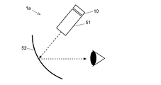
- the display device using the light guide 30 is used, a display device using the combiner 52 as shown in FIG. 3 can also be used.
- the display device 1a light constituting the image formed by the image forming unit 10 is reflected on the curved surface or flat surface of the combiner 52 through the virtual image display optical system 51, and enters the eye of the user. Thereby, the user can observe the virtual image displayed in front through the combiner 52.
- a head-up display can also be realized with the same configuration.
- the light source unit 11 including the LEDs emitting the three primary colors of red, green, and blue is used, a composite image or a monochrome image formed by combining one or two color images is displayed.
- the apparatus can be configured in the same manner as described above.
Landscapes
- Physics & Mathematics (AREA)
- General Physics & Mathematics (AREA)
- Optics & Photonics (AREA)
- Instrument Panels (AREA)
Abstract
La présente invention concerne un dispositif d'affichage (1) comprenant un module de formation d'image (10), un système optique de collimation (20) pour convertir la lumière émise par le module de formation d'image (10) en lumière parallèle, et un guide de lumière (30) pour agrandir la lumière parallèle. Le module de formation d'image (10) comprend : un élément optique (131) ayant une surface de paroi interne pour réfléchir totalement la lumière incidente avec un angle prescrit ou supérieur à ce dernier ; une source de lumière (11) qui émet de la lumière de telle sorte que la lumière soit incidente sur la surface de paroi avec un angle prescrit ou supérieur à ce dernier ; et un dispositif d'affichage de type à réflexion (14) constitué d'une pluralité de pièces de réflecteur en réseau bidimensionnelles ayant chacune une surface réfléchissante qui peut changer sa direction dans une première direction ou dans une seconde direction en fonction d'un signal de commande externe, une surface réfléchissante faisant face à la première direction étant disposée de manière à réfléchir la lumière réfléchie par la surface interne dans une direction différente de la direction d'incidence.
Priority Applications (4)
| Application Number | Priority Date | Filing Date | Title |
|---|---|---|---|
| EP17932069.2A EP3712681A4 (fr) | 2017-11-17 | 2017-11-17 | Dispositif d'affichage |
| US16/756,984 US20210373321A1 (en) | 2017-11-17 | 2017-11-17 | Display device |
| JP2019553645A JPWO2019097695A1 (ja) | 2017-11-17 | 2017-11-17 | 表示装置 |
| PCT/JP2017/041552 WO2019097695A1 (fr) | 2017-11-17 | 2017-11-17 | Dispositif d'affichage |
Applications Claiming Priority (1)
| Application Number | Priority Date | Filing Date | Title |
|---|---|---|---|
| PCT/JP2017/041552 WO2019097695A1 (fr) | 2017-11-17 | 2017-11-17 | Dispositif d'affichage |
Publications (1)
| Publication Number | Publication Date |
|---|---|
| WO2019097695A1 true WO2019097695A1 (fr) | 2019-05-23 |
Family
ID=66539425
Family Applications (1)
| Application Number | Title | Priority Date | Filing Date |
|---|---|---|---|
| PCT/JP2017/041552 WO2019097695A1 (fr) | 2017-11-17 | 2017-11-17 | Dispositif d'affichage |
Country Status (4)
| Country | Link |
|---|---|
| US (1) | US20210373321A1 (fr) |
| EP (1) | EP3712681A4 (fr) |
| JP (1) | JPWO2019097695A1 (fr) |
| WO (1) | WO2019097695A1 (fr) |
Cited By (3)
| Publication number | Priority date | Publication date | Assignee | Title |
|---|---|---|---|---|
| KR102156417B1 (ko) * | 2019-05-28 | 2020-09-15 | (주)엘비전테크 | 스위칭 미러 렌즈를 이용한 See-through 광학 시스템 |
| CN112285930A (zh) * | 2019-07-22 | 2021-01-29 | 苹果公司 | 用于头戴式设备的光学对准 |
| CN113109945A (zh) * | 2021-04-14 | 2021-07-13 | 安徽中科光栅科技有限公司 | 波导显示装置 |
Families Citing this family (1)
| Publication number | Priority date | Publication date | Assignee | Title |
|---|---|---|---|---|
| TW202346937A (zh) * | 2022-04-03 | 2023-12-01 | 以色列商魯姆斯有限公司 | 採用與光導集成的二向色組合器的顯示器 |
Citations (7)
| Publication number | Priority date | Publication date | Assignee | Title |
|---|---|---|---|---|
| JP2013117668A (ja) * | 2011-12-05 | 2013-06-13 | Nikon Corp | スペックル低減装置、プロジェクタ、およびスペックル低減装置の製造方法 |
| JP5299391B2 (ja) | 2004-03-29 | 2013-09-25 | ソニー株式会社 | 画像表示装置 |
| JP5698297B2 (ja) | 2000-06-05 | 2015-04-08 | ラマス リミテッド | 基板によって誘導される光学ビーム拡大器 |
| JP2015184561A (ja) | 2014-03-25 | 2015-10-22 | ソニー株式会社 | 導光装置、画像表示装置及び表示装置 |
| JP2015184560A (ja) * | 2014-03-25 | 2015-10-22 | ソニー株式会社 | 導光装置、画像表示装置及び表示装置 |
| JP2016031401A (ja) * | 2014-07-28 | 2016-03-07 | パナソニックIpマネジメント株式会社 | 表示装置 |
| JP2018004817A (ja) * | 2016-06-29 | 2018-01-11 | 株式会社リコー | 画像表示装置およびヘッドアップディスプレイシステム |
Family Cites Families (5)
| Publication number | Priority date | Publication date | Assignee | Title |
|---|---|---|---|---|
| US6560018B1 (en) * | 1994-10-27 | 2003-05-06 | Massachusetts Institute Of Technology | Illumination system for transmissive light valve displays |
| JP2007288169A (ja) * | 2006-03-24 | 2007-11-01 | Ricoh Co Ltd | 光学素子、照明装置および画像表示装置 |
| US7483200B1 (en) * | 2008-01-14 | 2009-01-27 | Spatial Photonics, Inc. | Multiple stop micro-mirror array display |
| US9076368B2 (en) * | 2012-02-06 | 2015-07-07 | Battelle Memorial Institute | Image generation systems and image generation methods |
| US9494800B2 (en) * | 2014-01-21 | 2016-11-15 | Osterhout Group, Inc. | See-through computer display systems |
-
2017
- 2017-11-17 WO PCT/JP2017/041552 patent/WO2019097695A1/fr unknown
- 2017-11-17 JP JP2019553645A patent/JPWO2019097695A1/ja active Pending
- 2017-11-17 EP EP17932069.2A patent/EP3712681A4/fr not_active Withdrawn
- 2017-11-17 US US16/756,984 patent/US20210373321A1/en not_active Abandoned
Patent Citations (8)
| Publication number | Priority date | Publication date | Assignee | Title |
|---|---|---|---|---|
| JP5698297B2 (ja) | 2000-06-05 | 2015-04-08 | ラマス リミテッド | 基板によって誘導される光学ビーム拡大器 |
| JP5299391B2 (ja) | 2004-03-29 | 2013-09-25 | ソニー株式会社 | 画像表示装置 |
| JP5447714B2 (ja) | 2004-03-29 | 2014-03-19 | ソニー株式会社 | 画像表示装置 |
| JP2013117668A (ja) * | 2011-12-05 | 2013-06-13 | Nikon Corp | スペックル低減装置、プロジェクタ、およびスペックル低減装置の製造方法 |
| JP2015184561A (ja) | 2014-03-25 | 2015-10-22 | ソニー株式会社 | 導光装置、画像表示装置及び表示装置 |
| JP2015184560A (ja) * | 2014-03-25 | 2015-10-22 | ソニー株式会社 | 導光装置、画像表示装置及び表示装置 |
| JP2016031401A (ja) * | 2014-07-28 | 2016-03-07 | パナソニックIpマネジメント株式会社 | 表示装置 |
| JP2018004817A (ja) * | 2016-06-29 | 2018-01-11 | 株式会社リコー | 画像表示装置およびヘッドアップディスプレイシステム |
Non-Patent Citations (2)
| Title |
|---|
| "SmartEyeglass Developer Edition", 24 October 2017, SONY MOBILE COMMUNICATIONS JAPAN, INC. |
| See also references of EP3712681A4 * |
Cited By (3)
| Publication number | Priority date | Publication date | Assignee | Title |
|---|---|---|---|---|
| KR102156417B1 (ko) * | 2019-05-28 | 2020-09-15 | (주)엘비전테크 | 스위칭 미러 렌즈를 이용한 See-through 광학 시스템 |
| CN112285930A (zh) * | 2019-07-22 | 2021-01-29 | 苹果公司 | 用于头戴式设备的光学对准 |
| CN113109945A (zh) * | 2021-04-14 | 2021-07-13 | 安徽中科光栅科技有限公司 | 波导显示装置 |
Also Published As
| Publication number | Publication date |
|---|---|
| JPWO2019097695A1 (ja) | 2020-04-02 |
| US20210373321A1 (en) | 2021-12-02 |
| EP3712681A1 (fr) | 2020-09-23 |
| EP3712681A4 (fr) | 2020-11-11 |
Similar Documents
| Publication | Publication Date | Title |
|---|---|---|
| CN112969955B (zh) | 具有二向色分束器颜色组合器的光学装置和系统 | |
| US7710655B2 (en) | Display with image-guiding substrate | |
| JP2022160457A (ja) | ウェアラブルディスプレイのための照明装置 | |
| JP4395802B2 (ja) | 画像表示装置 | |
| EP1626585B1 (fr) | Unité d'éclairage pour un dispositif de projection d'image | |
| WO2019097695A1 (fr) | Dispositif d'affichage | |
| US20220317467A1 (en) | Optical Devices Having Dichroic Beam Combiners, Optical Devices for Use with Dichroic Beam Combiners, and Methods of Manufacture Therefor | |
| JP2010510643A (ja) | 視覚表示用照明システム | |
| JP2003329978A (ja) | 照明装置および投射型表示装置 | |
| US11598971B2 (en) | Image device with a compact homogenizer | |
| KR101976991B1 (ko) | 웨어러블 디스플레이 장치 | |
| US11982818B2 (en) | Method and system for projection display with polarization selective reflectors | |
| CN108333781B (zh) | 近眼显示系统 | |
| JP2008107521A (ja) | 光源装置、照明装置及び画像表示装置 | |
| JP5239237B2 (ja) | 画像投影装置 | |
| CN112513718A (zh) | 用于rgb照明器的方法和系统 | |
| EP3843866A1 (fr) | Réseaux de couplage d'entrée dynamiques dans des systèmes d'imagerie | |
| JP2001194723A (ja) | 映像表示装置 | |
| JP2007279436A (ja) | 投射型画像表示装置 | |
| CN117826427A (zh) | 一种光机及ar设备 | |
| KR20220086456A (ko) | 3차원 증강 현실을 제공하는 증강 현실 장치 및 그 동작 방법 | |
| JP2009047881A (ja) | プロジェクタ | |
| JP2006145720A (ja) | 偏光変換素子、照明装置、及びプロジェクタ |
Legal Events
| Date | Code | Title | Description |
|---|---|---|---|
| 121 | Ep: the epo has been informed by wipo that ep was designated in this application |
Ref document number: 17932069 Country of ref document: EP Kind code of ref document: A1 |
|
| ENP | Entry into the national phase |
Ref document number: 2019553645 Country of ref document: JP Kind code of ref document: A |
|
| NENP | Non-entry into the national phase |
Ref country code: DE |
|
| ENP | Entry into the national phase |
Ref document number: 2017932069 Country of ref document: EP Effective date: 20200617 |