WO2019093243A1 - 風力発電装置付き照明設備 - Google Patents
風力発電装置付き照明設備 Download PDFInfo
- Publication number
- WO2019093243A1 WO2019093243A1 PCT/JP2018/040871 JP2018040871W WO2019093243A1 WO 2019093243 A1 WO2019093243 A1 WO 2019093243A1 JP 2018040871 W JP2018040871 W JP 2018040871W WO 2019093243 A1 WO2019093243 A1 WO 2019093243A1
- Authority
- WO
- WIPO (PCT)
- Prior art keywords
- foundation
- wind power
- power generator
- ground
- wind turbine
- Prior art date
- Legal status (The legal status is an assumption and is not a legal conclusion. Google has not performed a legal analysis and makes no representation as to the accuracy of the status listed.)
- Ceased
Links
Images






Classifications
-
- F—MECHANICAL ENGINEERING; LIGHTING; HEATING; WEAPONS; BLASTING
- F03—MACHINES OR ENGINES FOR LIQUIDS; WIND, SPRING, OR WEIGHT MOTORS; PRODUCING MECHANICAL POWER OR A REACTIVE PROPULSIVE THRUST, NOT OTHERWISE PROVIDED FOR
- F03D—WIND MOTORS
- F03D13/00—Assembly, mounting or commissioning of wind motors; Arrangements specially adapted for transporting wind motor components
- F03D13/20—Arrangements for mounting or supporting wind motors; Masts or towers for wind motors
-
- F—MECHANICAL ENGINEERING; LIGHTING; HEATING; WEAPONS; BLASTING
- F03—MACHINES OR ENGINES FOR LIQUIDS; WIND, SPRING, OR WEIGHT MOTORS; PRODUCING MECHANICAL POWER OR A REACTIVE PROPULSIVE THRUST, NOT OTHERWISE PROVIDED FOR
- F03D—WIND MOTORS
- F03D9/00—Adaptations of wind motors for special use; Combinations of wind motors with apparatus driven thereby; Wind motors specially adapted for installation in particular locations
- F03D9/10—Combinations of wind motors with apparatus storing energy
- F03D9/11—Combinations of wind motors with apparatus storing energy storing electrical energy
-
- F—MECHANICAL ENGINEERING; LIGHTING; HEATING; WEAPONS; BLASTING
- F03—MACHINES OR ENGINES FOR LIQUIDS; WIND, SPRING, OR WEIGHT MOTORS; PRODUCING MECHANICAL POWER OR A REACTIVE PROPULSIVE THRUST, NOT OTHERWISE PROVIDED FOR
- F03D—WIND MOTORS
- F03D9/00—Adaptations of wind motors for special use; Combinations of wind motors with apparatus driven thereby; Wind motors specially adapted for installation in particular locations
- F03D9/30—Wind motors specially adapted for installation in particular locations
- F03D9/34—Wind motors specially adapted for installation in particular locations on stationary objects or on stationary man-made structures
- F03D9/43—Wind motors specially adapted for installation in particular locations on stationary objects or on stationary man-made structures using infrastructure primarily used for other purposes, e.g. masts for overhead railway power lines
-
- F—MECHANICAL ENGINEERING; LIGHTING; HEATING; WEAPONS; BLASTING
- F21—LIGHTING
- F21S—NON-PORTABLE LIGHTING DEVICES; SYSTEMS THEREOF; VEHICLE LIGHTING DEVICES SPECIALLY ADAPTED FOR VEHICLE EXTERIORS
- F21S9/00—Lighting devices with a built-in power supply; Systems employing lighting devices with a built-in power supply
- F21S9/02—Lighting devices with a built-in power supply; Systems employing lighting devices with a built-in power supply the power supply being a battery or accumulator
- F21S9/03—Lighting devices with a built-in power supply; Systems employing lighting devices with a built-in power supply the power supply being a battery or accumulator rechargeable by exposure to light
-
- F—MECHANICAL ENGINEERING; LIGHTING; HEATING; WEAPONS; BLASTING
- F21—LIGHTING
- F21S—NON-PORTABLE LIGHTING DEVICES; SYSTEMS THEREOF; VEHICLE LIGHTING DEVICES SPECIALLY ADAPTED FOR VEHICLE EXTERIORS
- F21S9/00—Lighting devices with a built-in power supply; Systems employing lighting devices with a built-in power supply
- F21S9/04—Lighting devices with a built-in power supply; Systems employing lighting devices with a built-in power supply the power supply being a generator
-
- Y—GENERAL TAGGING OF NEW TECHNOLOGICAL DEVELOPMENTS; GENERAL TAGGING OF CROSS-SECTIONAL TECHNOLOGIES SPANNING OVER SEVERAL SECTIONS OF THE IPC; TECHNICAL SUBJECTS COVERED BY FORMER USPC CROSS-REFERENCE ART COLLECTIONS [XRACs] AND DIGESTS
- Y02—TECHNOLOGIES OR APPLICATIONS FOR MITIGATION OR ADAPTATION AGAINST CLIMATE CHANGE
- Y02B—CLIMATE CHANGE MITIGATION TECHNOLOGIES RELATED TO BUILDINGS, e.g. HOUSING, HOUSE APPLIANCES OR RELATED END-USER APPLICATIONS
- Y02B10/00—Integration of renewable energy sources in buildings
- Y02B10/30—Wind power
-
- Y—GENERAL TAGGING OF NEW TECHNOLOGICAL DEVELOPMENTS; GENERAL TAGGING OF CROSS-SECTIONAL TECHNOLOGIES SPANNING OVER SEVERAL SECTIONS OF THE IPC; TECHNICAL SUBJECTS COVERED BY FORMER USPC CROSS-REFERENCE ART COLLECTIONS [XRACs] AND DIGESTS
- Y02—TECHNOLOGIES OR APPLICATIONS FOR MITIGATION OR ADAPTATION AGAINST CLIMATE CHANGE
- Y02B—CLIMATE CHANGE MITIGATION TECHNOLOGIES RELATED TO BUILDINGS, e.g. HOUSING, HOUSE APPLIANCES OR RELATED END-USER APPLICATIONS
- Y02B20/00—Energy efficient lighting technologies, e.g. halogen lamps or gas discharge lamps
- Y02B20/72—Energy efficient lighting technologies, e.g. halogen lamps or gas discharge lamps in street lighting
-
- Y—GENERAL TAGGING OF NEW TECHNOLOGICAL DEVELOPMENTS; GENERAL TAGGING OF CROSS-SECTIONAL TECHNOLOGIES SPANNING OVER SEVERAL SECTIONS OF THE IPC; TECHNICAL SUBJECTS COVERED BY FORMER USPC CROSS-REFERENCE ART COLLECTIONS [XRACs] AND DIGESTS
- Y02—TECHNOLOGIES OR APPLICATIONS FOR MITIGATION OR ADAPTATION AGAINST CLIMATE CHANGE
- Y02E—REDUCTION OF GREENHOUSE GAS [GHG] EMISSIONS, RELATED TO ENERGY GENERATION, TRANSMISSION OR DISTRIBUTION
- Y02E10/00—Energy generation through renewable energy sources
- Y02E10/70—Wind energy
- Y02E10/72—Wind turbines with rotation axis in wind direction
-
- Y—GENERAL TAGGING OF NEW TECHNOLOGICAL DEVELOPMENTS; GENERAL TAGGING OF CROSS-SECTIONAL TECHNOLOGIES SPANNING OVER SEVERAL SECTIONS OF THE IPC; TECHNICAL SUBJECTS COVERED BY FORMER USPC CROSS-REFERENCE ART COLLECTIONS [XRACs] AND DIGESTS
- Y02—TECHNOLOGIES OR APPLICATIONS FOR MITIGATION OR ADAPTATION AGAINST CLIMATE CHANGE
- Y02E—REDUCTION OF GREENHOUSE GAS [GHG] EMISSIONS, RELATED TO ENERGY GENERATION, TRANSMISSION OR DISTRIBUTION
- Y02E10/00—Energy generation through renewable energy sources
- Y02E10/70—Wind energy
- Y02E10/728—Onshore wind turbines
-
- Y—GENERAL TAGGING OF NEW TECHNOLOGICAL DEVELOPMENTS; GENERAL TAGGING OF CROSS-SECTIONAL TECHNOLOGIES SPANNING OVER SEVERAL SECTIONS OF THE IPC; TECHNICAL SUBJECTS COVERED BY FORMER USPC CROSS-REFERENCE ART COLLECTIONS [XRACs] AND DIGESTS
- Y02—TECHNOLOGIES OR APPLICATIONS FOR MITIGATION OR ADAPTATION AGAINST CLIMATE CHANGE
- Y02E—REDUCTION OF GREENHOUSE GAS [GHG] EMISSIONS, RELATED TO ENERGY GENERATION, TRANSMISSION OR DISTRIBUTION
- Y02E70/00—Other energy conversion or management systems reducing GHG emissions
- Y02E70/30—Systems combining energy storage with energy generation of non-fossil origin
Definitions
- the present invention relates to a lighting installation with a wind power generator used for street lights and the like.
- the wind turbine generator 2 As a self-generating type street light that does not use a commercial power source, there is a type that stores electricity generated by a solar power generation device in a storage battery and lights a lighting fixture using the electricity stored in the storage battery.
- FIGS. 11 and 12 it is known that wind power generation equipment is additionally provided to compensate for the power shortage.
- the wind turbine generator 2 In the lighting installation with a wind turbine generator shown in FIGS. 11 and 12, the wind turbine generator 2, the solar power generator 3, and the lighting fixture 4 are provided on the top of the support 1.
- the lower end of the support 1 is fixed to the base 10.
- the foundation 10 is a cuboid caisson foundation, and as shown in FIG.
- the wind turbine of the wind turbine 2 rotates at high speed when the wind is strong.
- the excitation frequency of the wind turbine at the time of high speed rotation is that of the entire lighting installation including the support 1 and the wind power generator 2 attached to the support 1 and the solar power generator 3 etc. It may coincide with or be as close as possible to the resonant frequency. In that case, the support 1 vibrates largely due to resonance. This can be said about the lighting installation which does not have the solar power generation device 3 and generates electric power only with the wind power generation device 2.
- the following proposals have been made to prevent the above-mentioned resonance.
- the wind turbine is driven by resonance when the wind turbine that receives and rotates the wind power serves as the vibration source and the vibration frequency matches the natural frequency of the wind power generator. It is used as a measure against vibration, and the wind turbine is controlled by the wind turbine damping device.
- the “ ⁇ damping device” of Patent Document 2 is a mass damper type damping device provided on the top of a tower-like structure such as a pillar of a wind power generator. Since the same document does not describe special measures for the foundation of the tower structure, it seems that the same foundation as before is adopted.
- FIG. 1 in order to prevent resonance, it is effective to set the natural frequency of the wind power generation facility sufficiently higher than the bending frequency generated by the rotation of the wind turbine portion (to enhance the rigidity of the pole). Specifically, it is described that there are measures such as (1) increasing the diameter of the pole, (2) reinforcing the pole by providing a rib, and (3) tapering the shape of the pole.
- the cylindrical member (pole) supporting the wind turbine portion of the wind power generation facility the first cylindrical member supporting the wind turbine portion, and the second concentric with the first cylindrical portion It has been proposed to constitute a cylindrical member and to provide a damping material between the first and second cylindrical members.
- the “base of the offshore wind turbine” of Patent Document 4 supports the foundation receiving frame and the foundation block with steel pipe piles placed on the seabed, thereby eliminating cost for drilling work on the seabed. .
- piles are used as the foundation.
- Patent Documents 1 to 3 in order to prevent the resonance that is generated when the vibration frequency of the wind turbine matches the resonance frequency of the wind power generator, the vibration control device and the vibration control material are provided.
- Patent Document 3 describes that resonance can be prevented by increasing the natural frequency of the support, no measures utilizing that fact are taken.
- the excitation frequency of the wind turbine does not approach the resonance frequency even when the wind turbine is rotating at high speed, which leads to the prevention of resonance.
- it is not only the natural frequency of the pillars that determines the resonance frequency of the entire lighting equipment, but also the mass of the foundation that supports the stanchions, and the rigidity of the part of the foundation that contacts the ground "Stiffness.” That is, when the mass of the base increases, the resonance frequency of the entire lighting installation decreases, and when the support rigidity of the base increases, the resonance frequency of the entire lighting installation increases.
- the object of the present invention is to prevent the resonance with the wind turbine as an excitation source by increasing the resonance frequency of the entire lighting installation by increasing the supporting rigidity of the base while suppressing the increase of the base mass. It is providing a lighting installation with a wind power generator.
- At least a wind turbine and a lighting fixture are provided on a pillar built on the ground, electricity generated by the wind turbine is stored in a storage battery, and stored in the storage battery
- the maximum value of the dimension in the direction along the horizontal surface of the bottom surface of the foundation is made larger than the height dimension of the foundation, so that the sum of the reaction force that the foundation receives from the ground can be obtained without increasing the mass of the foundation. It can be enlarged to increase the support stiffness of the foundation. Thereby, the resonant frequency of the whole lighting installation becomes high. For this reason, even when the wind turbine is rotating at high speed, the vibration frequency of the wind turbine does not coincide with or as close as possible to the resonance frequency of the lighting equipment, and resonance using the wind turbine as a vibration source is prevented. it can.
- the bottom surface of the base may be provided with a recess.
- Providing a recess in the bottom of the foundation reduces the mass of the foundation, which increases the resonant frequency of the entire lighting installation.
- the contact area between the base and the ground becomes wider, so that the support rigidity of the base is increased, thereby increasing the resonance frequency of the entire lighting installation. In this way, the resonant frequency of the entire lighting installation can be increased from both the mass of the base and the support rigidity of the base.
- the inner wall surface of the recess may be an inclined surface positioned inward as it goes upward. Also in this case, the contact area between the foundation and the ground is increased, and the support rigidity of the foundation can be increased. If the inner wall surface of the recess is an inclined surface, there is an effect that it is difficult to separate the ground portion on the lower side of the foundation and the ground portion in the recess of the foundation, as compared to the case where the inner wall surface is a vertical surface.
- the outer peripheral surface of the foundation may be provided with an inclined surface portion which is inclined so as to be positioned inward toward the upper side.
- the foundation with the wide bottom area has a higher resonant frequency of the entire lighting installation than the narrow foundation.
- part or all of the foundation may be located above the ground surface of the ground.
- the contact area between the foundation and the ground is narrowed and the support rigidity of the foundation is lowered compared to the case where the foundation is embedded in the ground. Since the bottom surface is in contact with the ground, the decrease in support rigidity of the foundation is limited. For this reason, depending on the geographical conditions of the installation place, etc., the lighting equipment with a wind turbine may be installed so that a part or the whole of the foundation is located above the ground surface of the ground.
- the foundation may have a block-like foundation body to which the lower ends of the columns are fixed, and a pile which protrudes downward from the bottom surface of the foundation body and whose projection extends into the ground .
- a pile By adopting a pile, the mass of the foundation can be reduced.
- the reaction force from the ground is increased and the rigidity of the foundation is increased. From these things, the resonant frequency of the whole lighting installation can be made high.
- the wind turbine of the wind turbine may be a vertical axis wind turbine having a plurality of wings, or may be a horizontal axis wind turbine having a plurality of wings. In any case, the above-described functions and effects can be obtained.
- FIG. 1 is a perspective view of a lighting installation with a wind turbine generator according to a first embodiment of the present invention
- FIG. 2 is a front view showing the installation state thereof.
- a wind power generator 2 a solar power generator 3, and a lighting fixture 4 are provided on a pole 1 built on the ground.
- the wind turbine of the wind turbine generator 2 according to this embodiment is a vertical axis wind turbine 2A having a plurality of (for example, two) blades 2a.
- the column lower portion 1a has a diameter larger than that of the column upper portion 1b, and the storage battery 5 is built in the column lower portion 1a.
- the storage battery 5 stores the electricity generated by the wind power generation device 2 and the solar power generation device 3 and lights the lighting fixture 4 at night or the like using the stored electricity.
- the storage battery 5 may be provided at a location other than the support 1. Instead of providing the solar power generation device 3, power may be generated only by the wind power generation device 2.
- the support 1 is fixed to a block-shaped foundation 10 made of concrete or the like by an anchor bolt 11 at a flange portion 1c at the lower end.
- the foundation 10 of this embodiment is in the form of a rectangular parallelepiped, but may be in the form of a cylinder or another shape. As shown in FIG. 2, the foundation 10 is embedded in the ground 12, for example, with the upper surface exposed to the ground surface.
- the dimensions of the block-shaped foundation 10 are determined as follows. That is, as shown in FIG. 3, the maximum value B of the dimension of the bottom surface in the direction along the horizontal surface is larger than the height dimension D.
- the maximum value B is the dimension of the long side of a rectangle forming the bottom, and when the foundation 10 is cylindrical, the maximum value B is a circle forming the bottom.
- FIG. 4 is a diagram showing the magnitude of the reaction force that the foundation 10 receives from the ground 12.
- the reaction force (it shows by the arrow in the figure) which the side of foundation 10 receives becomes large in proportion to the depth of ground 12.
- the reaction force which the bottom surface of the foundation 10 receives is the same magnitude everywhere. Therefore, if the mass of the base 10 is the same, increasing the area of the bottom surface is more effective in increasing the support rigidity of the base 10 than increasing the area of the side surface.
- the resonance frequency of the entire lighting installation is increased.
- the excitation frequency of the wind turbine 2A will not coincide with or be as close as possible to the resonance frequency of the lighting equipment.
- resonance with the wind turbine 2A as an excitation source can be prevented.
- the natural frequency of the lighting installation including the foundation 10 is inversely proportional to the 1/2 power of the mass of the foundation 10. Therefore, it is not preferable to increase the mass of the base 10 because the natural frequency becomes low.
- the support rigidity of the foundation 10 can be increased without increasing the mass of the foundation 10, and the resonant frequency of the entire lighting installation Can be raised.
- the base 10 shown in FIG. 5 is provided with a recess 20 on the bottom surface.
- the inner wall surface 20a of the recess 20 is a plane perpendicular to the horizontal plane.
- the mass of the base 10 is reduced, thereby increasing the resonant frequency of the entire lighting installation.
- the area in which the foundation 10 contacts the ground 12 becomes wider, so the support rigidity of the foundation 10 and the ground 12 is increased, thereby increasing the resonance frequency of the entire lighting equipment.
- the foundation 10 shown in FIG. 6 is one in which the inner wall surface 21a of the recess 21 provided on the bottom surface is an inclined surface positioned inward as it goes upward.
- the "inside” is the center side.
- the contact area between the foundation 10 and the ground 12 is increased, and the support rigidity of the foundation 10 can be increased.
- the inner wall surface 21a of the recess 21 is an inclined surface, compared with the case where the inner wall surface is a vertical surface (FIG. 5), the ground portion under the foundation 10 and the ground portion in the recess 21 of the foundation Has the effect of being difficult to separate.
- the foundation 10 shown in FIG. 7 is inclined such that it is positioned on the outer peripheral surface inward as it goes upward, in addition to the recess 21 similar to the recess 21 of the foundation 10 shown in FIG.
- An inclined surface portion 23 is provided.
- the foundation with the wide bottom area has a higher resonant frequency of the entire lighting installation than the narrow foundation.
- the area of the bottom surface can be increased without changing the mass. Thereby, the resonant frequency of the whole lighting installation can be made high.
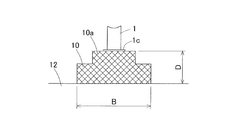
- the foundation 10 shown in FIG. 8 is entirely located above the ground surface of the ground 12, and only the bottom surface is in contact with the ground 12. Although the foundation 10 is stepped in the illustrated example, it may have other shapes. As shown in FIG. 8, the entire foundation 10 is not limited to being located above the ground surface of the ground 12, and only a portion of the foundation 10, for example, only the portion 10 a above the step portion is the ground of the ground 12. It may be located above the surface.
- the contact area between the foundation 10 and the ground 12 is narrower than when the entire foundation 10 is embedded in the ground 12.
- the support rigidity of the foundation 10 is reduced, the decrease in support rigidity of the foundation 10 is limited because the bottom surface of the foundation 10 is in contact with the ground 12. For this reason, depending on the geographical conditions of the installation location, etc., the lighting equipment with a wind turbine may be installed so that a part or the whole of the foundation 10 is located above the ground surface of the ground 12.
- the foundation 10 shown in FIG. 9 includes a block-shaped foundation main body 24 to which the lower end of the support 1 is fixed, and a plurality of piles 25 projecting downward from the bottom surface of the foundation main body 24 and extending to the ground 12. .
- the mass of the foundation 10 can be reduced by adopting the pile 25. Moreover, by increasing the surface area where the pile 25 and the ground 12 contact, the reaction force from the ground 12 is increased, and the rigidity of the foundation 10 is increased. From these things, the resonant frequency of the whole lighting installation can be made high.
- the lighting equipment with wind turbines shown in Figs. 1 and 2 uses a two-bladed vertical axis wind turbine 2A as a wind turbine, but using the vertical axis wind turbine 2A having three or more wings 2a. It is also good. Further, as shown in FIG. 10, a horizontal axis wind turbine 2B having a plurality of blades 2b may be used as a wind turbine. In any case, the above-mentioned respective actions and effects can be obtained.
Landscapes
- Engineering & Computer Science (AREA)
- General Engineering & Computer Science (AREA)
- Life Sciences & Earth Sciences (AREA)
- Sustainable Development (AREA)
- Sustainable Energy (AREA)
- Chemical & Material Sciences (AREA)
- Combustion & Propulsion (AREA)
- Mechanical Engineering (AREA)
- Power Engineering (AREA)
- Wind Motors (AREA)
- Non-Portable Lighting Devices Or Systems Thereof (AREA)
Abstract
基礎の質量の増大を抑えつつ、基礎の支持剛性を増大させて、照明設備全体の共振周波数を高くすることにより、風車を加振源とする共振を防止することができる風力発電装置付き照明設備を提供する。風力発電装置付き照明設備は、地面に建てられた支柱(1)に少なくとも風力発電装置(2)および照明器具(4)が設けられている。風力発電装置(2)で発電された電気を蓄電池(5)に蓄電し、この蓄電池に蓄電されている電気を使って照明器具(4)を点灯させる。支柱(1)の下端が固定され地盤(12)に対して支柱(1)を支持する基礎(10)を有する。基礎(10)の底面における水平面に沿う方向の寸法の最大値が、基礎(10)の高さ寸法よりも大きい。
Description
この出願は、2017年11月8日出願の特願2017-215437の優先権を主張するものであり、その全体を参照によりこの出願の一部をなすものとして引用する。
この発明は、街路灯等に使用される風力発電装置付き照明設備に関する。
商用電源を使用しない自己発電型の街路灯として、太陽光発電装置により発電された電気を蓄電池に蓄電し、この蓄電池に蓄電された電気を使って照明器具を点灯させるものがある。しかし、太陽光発電装置だけでは日照時間が少ない場合に十分な発電ができないことから、図11、図12に示すように、電力不足を補うために風力発電装置を併設したものが知られている。図11、図12に図示する風力発電装置付き照明設備は、支柱1の上部に風力発電装置2、太陽光発電装置3、および照明器具4が設けられている。支柱1の下端は、基礎10に固定されている。図示例の場合、基礎10は直方体のケーソン基礎であって、図12のように、地盤12に埋め込んで設置される。
風力発電装置2の風車は、強風時に高速で回転する。風車を支持する支柱1の剛性が小さい場合、高速回転時の風車の加振周波数が、支柱1とこの支柱1に取り付けられた風力発電装置2、太陽光発電装置3等を含む照明設備全体の共振周波数と一致または限りなく近づくことがある。その場合、支柱1が共振により大きく振動する。このことは、太陽光発電装置3を有しておらず、風力発電装置2のみで発電する照明設備についても言える。
上記共振を防止するために、例えば以下の提案がなされている。特許文献1の「風車用制振装置~」は、風力を受けて回転する風車が加振源となり、加振周波数が風力発電装置の固有振動数と一致した場合に、共振により風力発電装置が振動することへの対策として用いられ、風車用制振装置により風車を制振するようにしている。
特許文献2の「~制振装置」は、風力発電装置の支柱等のタワー状建造物の上部に設けられるマスダンパー型の制振装置である。同文献には、タワー状建造物の基礎に対して特別な対策が記載されていないので、従来と同様の基礎が採用されると思われる。
特許文献3の「風力発電設備用の円筒部材」には、垂直回転型風車を備えた風力発電設備に適用した例が示されている。同文献に、共振を防止するためには、風力発電設備の固有振動数を風車部の回転により生じる曲げ振動数よりも十分に高く設定する(ポールの剛性を高める)ことが有効であり、具体的に、(1)ポールの径を大きくする、(2)リブを設けてポールを補強する、(3)ポールの形状をテーパ状にする等の対策があることが記載されている。しかし、これらの対策にはそれぞれ課題があることから、風力発電設備の風車部を支持する円筒部材(ポール)を、風車部を支持する第一円筒部材と、第一円筒部と同心の第二円筒部材とで構成し、これら第一および第二円筒部材の間に制振材を設けることが提案されている。
特許文献4の「洋上風力発電装置の基礎~」は、海底に打設した鋼管杭により、基礎受けフレームと基礎ブロックを支持することで、海底の掘削作業を不要にしてコスト削減を図っている。このように、洋上風力発電装置では、基礎に杭が用いられる。
上記のように、特許文献1~3では、風車の加振周波数が風力発電装置の共振周波数と一致することで発生する共振を防止するために、制振装置や制振材を設けている。特許文献3には、支柱の固有振動数を高くすることで共振を防止できることが記載されているが、そのことを利用した対策はとっていない。
風力発電装置付き照明設備において、照明設備全体の共振周波数を高くすれば、風車が高速回転している時でも風車の加振周波数が前記共振周波数に近づくことがなくなり、共振の防止につながる。ところで、照明設備全体の共振周波数を決定するのは、支柱の固有振動数だけではなく、支柱を支持する基礎の質量や、基礎における地盤に対して接触する部分の剛性(以下、「基礎の支持剛性」とする。)が影響する。つまり、基礎の質量が増加すると照明設備全体の共振周波数が低くなり、基礎の支持剛性が大きくなると、照明設備全体の共振周波数が高くなる。
基礎の支持剛性を増加させるためには、基礎と地盤との接地面積を大きくすることが有効である。しかし、単に基礎の寸法を大きくするのでは、基礎の質量が増大して、照明設備全体の共振周波数を低くしてしまうため、有効な対策にならない。したがって、基礎の質量の増大を抑えつつ、基礎の支持剛性を増大させることが重要である。
この発明の目的は、基礎の質量の増大を抑えつつ、基礎の支持剛性を増大させて、照明設備全体の共振周波数を高くすることにより、風車を加振源とする共振を防止することができる風力発電装置付き照明設備を提供することである。
この発明の風力発電装置付き照明設備は、地面に建てられた支柱に少なくとも風力発電装置および照明器具が設けられ、前記風力発電装置で発電された電気を蓄電池に蓄電し、この蓄電池に蓄電されている電気を使って前記照明器具を点灯させる風力発電装置付き照明設備であって、前記支柱の下端が固定され地盤に対して前記支柱を支持する基礎を有し、この基礎の底面における水平面に沿う方向の寸法の最大値が、前記基礎の高さ寸法よりも大きい。
この構成によると、基礎の底面における水平面に沿う方向の寸法の最大値を基礎の高さ寸法よりも大きくしたことにより、基礎の質量を増大させずに、基礎が地盤から受ける反力の総和を大きくして、基礎の支持剛性を増大させることができる。それにより、照明設備全体の共振周波数が高くなる。このため、風車の高速回転時においても、風車の加振周波数が照明設備の共振周波数と一致したり、あるいは限りなく近づいたりすることがなく、風車を加振源とする共振を防止することができる。
この発明において、前記基礎の底面に凹部が設けられていてもよい。基礎の底面に凹部を設けると、基礎の質量が小さくなり、それにより照明設備全体の共振周波数が高くなる。また、凹部を設けると、基礎と地盤との接触面積がより広くなるため、基礎の支持剛性が増大し、それにより照明設備全体の共振周波数が高くなる。このように、基礎の質量、および基礎の支持剛性の両面から、照明設備全体の共振周波数を高くすることができる。
前記凹部の内壁面は、上側に行くに従い内側に位置する傾斜面であってもよい。この場合も、基礎と地盤との接触面積が広くなり、基礎の支持剛性を増大させることができる。えて、凹部の内壁面が傾斜面であると、内壁面が垂直面である場合と比べて、基礎の下側の地盤部分と基礎の凹部内の地盤部分とが分離し難いという効果がある。
この発明において、前記基礎の外周面に、上側に行くに従い内側に位置するように傾斜する傾斜面部が設けられていてもよい。質量が同じで底面の面積が互いに異なる二つの基礎を比べた場合、底面の面積が広い基礎の方が狭い基礎よりも、照明設備全体の共振周波数が高い。基礎の外周面に傾斜面部を設けることで、質量を変えずに底面の面積を広くすることができる。これにより、照明設備全体の共振周波数を高くすることができる。
この発明において、前記基礎の一部または全体が前記地盤の地表面よりも上側に位置していてもよい。基礎が地盤の地表面よりも上側に位置していると、基礎が地盤に埋め込まれている場合と比べて、基礎と地盤との接触面積が狭くなり基礎の支持剛性が低下するが、基礎の底面は地盤に接しているため、基礎の支持剛性の低下は限定的である。このため、設置場所の地理的条件等によっては、基礎の一部または全体が地盤の地表面よりも上側に位置に位置するように風力発電装置付き照明設備を設置しても構わない。
この発明において、前記基礎は、前記支柱の下端が固定されるブロック状の基礎本体と、この基礎本体の底面から下方に突出しその突出部が前記地盤中に延びる杭とを有していてもよい。杭を採用することで、基礎の質量を小さくできる。また、杭と地盤とが接触する表面積を大きくすることで、地盤からの反力が増加して、基礎の剛性が増大する。これらのことから、照明設備全体の共振周波数を高くすることができる。
この発明において、前記風力発電装置の風車は、複数枚の翼を有する垂直軸風車であってもよく、また複数枚の翼を有する水平軸風車であってもよい。いずれの場合も、上記各作用・効果が得られる。
この発明は、添付の図面を参考にした以下の好適な実施形態の説明から、より明確に理解されるであろう。しかしながら、実施形態および図面は単なる図示および説明のためのものであり、この発明の範囲を定めるために利用されるべきものではない。この発明の範囲は添付の請求の範囲によって定まる。添付図面において、複数の図面における同一の符号は、同一または相当する部分を示す。
この発明の第1実施形態に係る風力発電装置付き照明設備の斜視図である。
同風力発電装置付き照明設備の設置状態を示す正面図である。
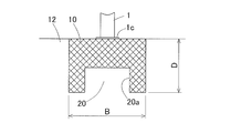
同風力発電装置付き照明設備の基礎の縦断面図である。
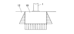
基礎が地盤から受ける反力の大きさを示す図である。
他の基礎の断面形状を示す図である。
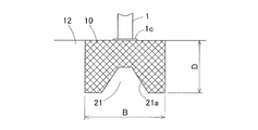
さらに他の基礎の断面形状を示す図である。
さらに他の基礎の断面形状を示す図である。
さらに他の基礎の断面形状を示す図である。
さらに他の基礎の断面形状を示す図である。
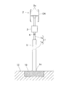
この発明の第2実施形態に係る風力発電装置付き照明設備の設置状態を示す図である。
従来の風力発電装置付き照明設備の斜視図である。
同風力発電装置付き照明設備の設置状態を示す図である。
この発明の実施形態を図面と共に説明する。図1はこの発明の第1実施形態に係る風力発電装置付き照明設備の斜視図、図2はその設置状態を示す正面図である。この照明設備は、地面に建てられた支柱1に、風力発電装置2、太陽光発電装置3、および照明器具4が設けられている。この実施形態の風力発電装置2の風車は、複数枚(例えば2枚)の翼2aを有する垂直軸風車2Aである。支柱下部1aは支柱上部1bよりも径が太くなっていて、この支柱下部1aに蓄電池5が内蔵されている。蓄電池5は、風力発電装置2および太陽光発電装置3で発電された電気を蓄電し、その蓄電された電気を使って夜間等に照明器具4を点灯させる。支柱1以外の箇所に蓄電池5が設けられていてもよい。太陽光発電装置3を設けずに、風力発電装置2のみで発電するようにしてもよい。
支柱1は、下端のフランジ部1cで、コンクリート等からなるブロック状の基礎10に、アンカーボルト11によって固定されている。この実施形態の基礎10は、直方体形状であるが、円柱形状あるいは他の形状であってもよい。図2に示すように、基礎10は、例えば上面を地表に露出させて地盤12に埋め込まれる。
ブロック状の基礎10は、その寸法が次のように定められている。すなわち、図3に示すように、底面における水平面に沿う方向の寸法の最大値Bが、高さ寸法Dよりも大きい。この実施形態のように基礎10が直方体形状である場合、前記最大値Bは底面を成す長方形の長辺の寸法であり、基礎10が円柱状である場合、前記最大値Bは底面を成す円の直径である。
上記のように寸法を定める理由について説明する。図4は、基礎10が地盤12から受ける反力の大きさを示す図である。同図に示すように、基礎10の側面が受ける反力(図中、矢印で示す)は、地盤12の深さに比例して大きくなる。これに対し、基礎10の底面が受ける反力は、どこでも同じ大きさである。従って、基礎10の質量が同じである場合、側面の面積を広くするよりも、底面の面積を広くすることが、基礎10の支持剛性を増大させることに有効である。
基礎10の支持剛性が増大することで、照明設備全体の共振周波数が高くなる。これにより、風車2Aの高速回転時においても、風車2Aの加振周波数が照明設備の共振周波数と一致したり、あるいは限りなく近づいたりすることがなくなる。その結果、風車2Aを加振源とする共振を防止することができる。
なお、基礎10を含む照明設備の固有振動数は、基礎10の質量の1/2乗に反比例する。よって、基礎10の質量を増やすのは、固有振動数が低くなるため、好ましくない。底面の寸法の最大値Bと高さ寸法Dとの関係を上記のように定めることにより、基礎10の質量を大きくすることなく、基礎10の支持剛性を増大させて、照明設備全体の共振周波数を高くすることができる。
つまり、底面の寸法の最大値B<高さ寸法Dとした場合に対して、図3に示すように、底面の寸法の最大値B>高さ寸法Dとすると、図4に示すように側面よりも底面の剛性が大きくなることから、共振周波数が大きくなり、共振が生じ難くなる。
[基礎の他の形状]
図5に示す基礎10は、底面に凹部20が設けられている。凹部20の内壁面20aは、水平面に対して垂直面である。
図5に示す基礎10は、底面に凹部20が設けられている。凹部20の内壁面20aは、水平面に対して垂直面である。
基礎10の底面に凹部20を設けると、基礎10の質量が低減し、それにより照明設備全体の共振周波数が高くなる。また、凹部20を設けると、基礎10が地盤12と接する面積がより広くなるため、基礎10と地盤12の支持剛性を増大し、それにより照明設備全体の共振周波数が高くなる。このように、基礎10の質量、および基礎10と地盤12の支持剛性の両面から、照明設備全体の共振周波数を高くすることができる。
図6に示す基礎10は、底面に設けられた凹部21の内壁面21aを、上側に行くに従い内側に位置する傾斜面としたものである。「内側」とは、中心側のことである。
この場合も、図5の例と同様に、基礎10と地盤12との接触面積が広くなり、基礎10の支持剛性を増大させることができる。加えて、凹部21の内壁面21aが傾斜面であると、内壁面が垂直面である場合(図5)と比べて、基礎10の下側の地盤部分と基礎の凹部21内の地盤部分とが分離し難いという効果がある。
図7に示す基礎10は、底面に図6に示す基礎10の凹部21と同様の凹部21が設けられていることに加えて、外周面に、上側に行くに従い内側に位置するように傾斜する傾斜面部23が設けられている。
質量が同じで底面の面積が互いに異なる二つの基礎を比べた場合、底面の面積が広い基礎の方が狭い基礎よりも、照明設備全体の共振周波数が高い。図7のように、基礎10の外周面に傾斜面部23を設けることで、質量を変えずに底面の面積を広くすることができる。これにより、照明設備全体の共振周波数を高くすることができる。
図8に示す基礎10は、全体が地盤12の地表面よりも上側に位置していて、底面のみが地盤12に接触している。図の例では、基礎10が段付きの形状であるが、他の形状であってもよい。図8のように、基礎10の全体が地盤12の地表面よりも上側に位置することに限らず、基礎10の一部だけ、例えば段の部分よりも上の部分10aのみが地盤12の地表面よりも上側に位置していてもよい。
基礎10の一部または全体が地盤12の地表面よりも上側に位置していると、基礎10全体が地盤12に埋め込まれている場合と比べて、基礎10と地盤12との接触面積が狭くなり基礎10の支持剛性が低下するが、基礎10の底面は地盤12に接しているため、基礎10の支持剛性の低下は限定的である。このため、設置場所の地理的条件等によっては、基礎10の一部または全体が地盤12の地表面よりも上側に位置するように風力発電装置付き照明設備を設置しても構わない。
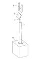
図9に示す基礎10は、支柱1の下端が固定されるブロック状の基礎本体24と、この基礎本体24の底面から下方に突出しその突出部が地盤12に延びる複数本の杭25とからなる。
杭25を採用することで、基礎10の質量を小さくできる。また、杭25と地盤12とが接触する表面積を大きくすることで、地盤12からの反力が増加して、基礎10の剛性を増大する。これらのことから、照明設備全体の共振周波数を高くすることができる。
図1、図2に示す風力発電装置付き照明設備は、風車として、2枚翼の垂直軸風車2Aが使用されているが、翼2aの数が3枚以上の垂直軸風車2Aを使用してもよい。また、図10に示すように、風車として、複数枚の翼2bを有する水平軸風車2Bを使用してもよい。いずれの場合も、前記各作用・効果が得られる。
以上のとおり、図面を参照しながら好適な実施形態を説明したが、当業者であれば、本件明細書を見て、自明な範囲内で種々の変更および修正を容易に想定するであろう。したがって、そのような変更および修正は、請求の範囲から定まる発明の範囲内のものと解釈される。
1…支柱
2…風力発電装置
2A…垂直軸風車
2B…水平軸風車
3…太陽光発電装置
4…照明器具
5…蓄電池
10…基礎
12…地盤
20…凹部
20a…内壁面
21…凹部
21a…内壁面
23…傾斜面部
24…基礎本体
25…杭
B…基礎の底面における水平面に沿う方向の寸法の最大値
D…基礎の高さ寸法
2…風力発電装置
2A…垂直軸風車
2B…水平軸風車
3…太陽光発電装置
4…照明器具
5…蓄電池
10…基礎
12…地盤
20…凹部
20a…内壁面
21…凹部
21a…内壁面
23…傾斜面部
24…基礎本体
25…杭
B…基礎の底面における水平面に沿う方向の寸法の最大値
D…基礎の高さ寸法
Claims (8)
- 地面に建てられた支柱に少なくとも風力発電装置および照明器具が設けられ、前記風力発電装置で発電された電気を蓄電池に蓄電し、この蓄電池に蓄電されている電気を使って前記照明器具を点灯させる風力発電装置付き照明設備であって、
前記支柱の下端が固定され地盤に対して前記支柱を支持する基礎を有し、この基礎の底面における水平面に沿う方向の寸法の最大値が、前記基礎の高さ寸法よりも大きい風力発電装置付き照明設備。 - 請求項1に記載の風力発電装置付き照明設備において、前記基礎の底面に凹部が設けられた風力発電装置付き照明設備。
- 請求項2に記載の風力発電装置付き照明設備において、前記凹部の内壁面は、上側に行くに従い内側に位置する傾斜面である風力発電装置付き照明設備。
- 請求項1ないし請求項3のいずれか1項に記載の風力発電装置付き照明設備において、前記基礎の外周面に、上側に行くに従い内側に位置するように傾斜する傾斜面部が設けられている風力発電装置付き照明設備。
- 請求項1ないし請求項4のいずれか1項に記載の風力発電装置付き照明設備において、前記基礎の一部または全体が前記地盤の地表面よりも上側に位置する風力発電装置付き照明設備。
- 請求項1ないし請求項5のいずれか1項に記載の風力発電装置付き照明設備において、前記基礎は、前記支柱の下端が固定されるブロック状の基礎本体と、この基礎本体の底面から下方に突出しその突出部が前記地盤中に延びる杭とを有する風力発電装置付き照明設備。
- 請求項1ないし請求項6のいずれか1項に記載の風力発電装置付き照明設備において、前記風力発電装置の風車は、複数枚の翼を有する垂直軸風車である風力発電装置付き照明設備。
- 請求項1ないし請求項6のいずれか1項に記載の風力発電装置付き照明設備において、前記風力発電装置の風車は、複数枚の翼を有する水平軸風車である風力発電装置付き照明設備。
Applications Claiming Priority (2)
| Application Number | Priority Date | Filing Date | Title |
|---|---|---|---|
| JP2017-215437 | 2017-11-08 | ||
| JP2017215437A JP2019085937A (ja) | 2017-11-08 | 2017-11-08 | 風力発電装置付き照明設備 |
Publications (1)
| Publication Number | Publication Date |
|---|---|
| WO2019093243A1 true WO2019093243A1 (ja) | 2019-05-16 |
Family
ID=66439132
Family Applications (1)
| Application Number | Title | Priority Date | Filing Date |
|---|---|---|---|
| PCT/JP2018/040871 Ceased WO2019093243A1 (ja) | 2017-11-08 | 2018-11-02 | 風力発電装置付き照明設備 |
Country Status (2)
| Country | Link |
|---|---|
| JP (1) | JP2019085937A (ja) |
| WO (1) | WO2019093243A1 (ja) |
Citations (5)
| Publication number | Priority date | Publication date | Assignee | Title |
|---|---|---|---|---|
| JPH1162811A (ja) * | 1997-08-11 | 1999-03-05 | Akiji Matoba | 風力を繰返し利用する風車発電装置及び強風遮断装置 |
| JP2004308427A (ja) * | 2003-04-01 | 2004-11-04 | Technical Support:Kk | 風力発電装置 |
| JP2006029226A (ja) * | 2004-07-16 | 2006-02-02 | Suzuki Sangyo Kk | 風力発電装置・照明装置 |
| JP2010106656A (ja) * | 2008-11-03 | 2010-05-13 | Siemens Ag | 特に風車のための基礎及び風車 |
| JP2011099299A (ja) * | 2009-11-09 | 2011-05-19 | Takenaka Komuten Co Ltd | 構造物 |
-
2017
- 2017-11-08 JP JP2017215437A patent/JP2019085937A/ja active Pending
-
2018
- 2018-11-02 WO PCT/JP2018/040871 patent/WO2019093243A1/ja not_active Ceased
Patent Citations (5)
| Publication number | Priority date | Publication date | Assignee | Title |
|---|---|---|---|---|
| JPH1162811A (ja) * | 1997-08-11 | 1999-03-05 | Akiji Matoba | 風力を繰返し利用する風車発電装置及び強風遮断装置 |
| JP2004308427A (ja) * | 2003-04-01 | 2004-11-04 | Technical Support:Kk | 風力発電装置 |
| JP2006029226A (ja) * | 2004-07-16 | 2006-02-02 | Suzuki Sangyo Kk | 風力発電装置・照明装置 |
| JP2010106656A (ja) * | 2008-11-03 | 2010-05-13 | Siemens Ag | 特に風車のための基礎及び風車 |
| JP2011099299A (ja) * | 2009-11-09 | 2011-05-19 | Takenaka Komuten Co Ltd | 構造物 |
Also Published As
| Publication number | Publication date |
|---|---|
| JP2019085937A (ja) | 2019-06-06 |
Similar Documents
| Publication | Publication Date | Title |
|---|---|---|
| KR101384165B1 (ko) | 해상풍력 기초의 세굴방지용 캡 | |
| JP2021510793A (ja) | 風力および太陽光発電のためのマルチ風力タービンおよびソーラーを支持する風に対向して自己整列する浮体式プラットフォーム、ならびにその構築方法 | |
| JP7313212B2 (ja) | 洋上施設用浮体構造物及びその設置構造 | |
| WO2021070786A1 (ja) | 着床式洋上架台、洋上風力発電装置及び洋上風況観測装置 | |
| JP2011108854A (ja) | 太陽光発電装置の設置構造及び設置方法 | |
| EP2327619A2 (en) | A wind turbine installation vessel and an adjustment device for its center of gravity | |
| KR101354591B1 (ko) | 자세 평형 유지 기능을 갖는 부유식 해상 풍력 발전기 | |
| JP2018115636A (ja) | 水上風力発電施設支持構造物およびその施工方法 | |
| KR20120002184A (ko) | 해상 풍력발전장치 | |
| KR101383159B1 (ko) | 암반 설치용 중력식 해상풍력 기초 슬래브 | |
| WO2019093243A1 (ja) | 風力発電装置付き照明設備 | |
| KR101501652B1 (ko) | 해상풍력발전 하부구조물 | |
| KR101383596B1 (ko) | 유공을 이용한 해상풍력 지지구조물 및 그 시공방법 | |
| KR101689884B1 (ko) | 탑상 구조물의 기초 구조 | |
| KR20130047950A (ko) | 해상 풍력 발전기의 지지구조물 및 그 설치방법 | |
| KR101304934B1 (ko) | 멀티복합하이브리드기초형 해상풍력타워 | |
| KR101549194B1 (ko) | 모노파일 타입의 해상 풍력발전기 구조물 및 그 설치방법 | |
| JP2013079536A (ja) | 支柱の設置構造 | |
| KR101384168B1 (ko) | 위치센서를 이용한 해상풍력 발전기의 기초슬래브 설치 방법 | |
| KR101409975B1 (ko) | 태양전지판 설치용 기초파일 | |
| JP2014163167A (ja) | 杭柱及びその施工方法 | |
| KR101432272B1 (ko) | 부유식 해상 풍력발전기의 운동 감쇄 장치 | |
| KR20160044241A (ko) | 부유식 풍력발전장치의 하부구조물 | |
| JP7492283B1 (ja) | 着床式洋上架台の構築方法、着床式洋上架台、及び洋上風力発電装置 | |
| KR101427603B1 (ko) | 절단 스파형 부유식 해상풍력 플랫폼 |
Legal Events
| Date | Code | Title | Description |
|---|---|---|---|
| 121 | Ep: the epo has been informed by wipo that ep was designated in this application |
Ref document number: 18875168 Country of ref document: EP Kind code of ref document: A1 |
|
| NENP | Non-entry into the national phase |
Ref country code: DE |
|
| 122 | Ep: pct application non-entry in european phase |
Ref document number: 18875168 Country of ref document: EP Kind code of ref document: A1 |