WO2019088202A1 - 家畜舎システム - Google Patents
家畜舎システム Download PDFInfo
- Publication number
- WO2019088202A1 WO2019088202A1 PCT/JP2018/040585 JP2018040585W WO2019088202A1 WO 2019088202 A1 WO2019088202 A1 WO 2019088202A1 JP 2018040585 W JP2018040585 W JP 2018040585W WO 2019088202 A1 WO2019088202 A1 WO 2019088202A1
- Authority
- WO
- WIPO (PCT)
- Prior art keywords
- pipe
- medium
- heat
- livestock
- temperature
- Prior art date
- Legal status (The legal status is an assumption and is not a legal conclusion. Google has not performed a legal analysis and makes no representation as to the accuracy of the status listed.)
- Ceased
Links
Images

Classifications
-
- A—HUMAN NECESSITIES
- A01—AGRICULTURE; FORESTRY; ANIMAL HUSBANDRY; HUNTING; TRAPPING; FISHING
- A01K—ANIMAL HUSBANDRY; AVICULTURE; APICULTURE; PISCICULTURE; FISHING; REARING OR BREEDING ANIMALS, NOT OTHERWISE PROVIDED FOR; NEW BREEDS OF ANIMALS
- A01K1/00—Housing animals; Equipment therefor
- A01K1/0047—Air-conditioning, e.g. ventilation, of animal housings
- A01K1/0082—Water misting or cooling systems
-
- A—HUMAN NECESSITIES
- A01—AGRICULTURE; FORESTRY; ANIMAL HUSBANDRY; HUNTING; TRAPPING; FISHING
- A01K—ANIMAL HUSBANDRY; AVICULTURE; APICULTURE; PISCICULTURE; FISHING; REARING OR BREEDING ANIMALS, NOT OTHERWISE PROVIDED FOR; NEW BREEDS OF ANIMALS
- A01K1/00—Housing animals; Equipment therefor
-
- A—HUMAN NECESSITIES
- A01—AGRICULTURE; FORESTRY; ANIMAL HUSBANDRY; HUNTING; TRAPPING; FISHING
- A01K—ANIMAL HUSBANDRY; AVICULTURE; APICULTURE; PISCICULTURE; FISHING; REARING OR BREEDING ANIMALS, NOT OTHERWISE PROVIDED FOR; NEW BREEDS OF ANIMALS
- A01K1/00—Housing animals; Equipment therefor
- A01K1/0005—Stable partitions
- A01K1/0011—Cubicle partitions
-
- A—HUMAN NECESSITIES
- A01—AGRICULTURE; FORESTRY; ANIMAL HUSBANDRY; HUNTING; TRAPPING; FISHING
- A01K—ANIMAL HUSBANDRY; AVICULTURE; APICULTURE; PISCICULTURE; FISHING; REARING OR BREEDING ANIMALS, NOT OTHERWISE PROVIDED FOR; NEW BREEDS OF ANIMALS
- A01K1/00—Housing animals; Equipment therefor
- A01K1/0047—Air-conditioning, e.g. ventilation, of animal housings
- A01K1/0076—Arrangement of heaters or heat exchangers
-
- F—MECHANICAL ENGINEERING; LIGHTING; HEATING; WEAPONS; BLASTING
- F24—HEATING; RANGES; VENTILATING
- F24D—DOMESTIC- OR SPACE-HEATING SYSTEMS, e.g. CENTRAL HEATING SYSTEMS; DOMESTIC HOT-WATER SUPPLY SYSTEMS; ELEMENTS OR COMPONENTS THEREFOR
- F24D3/00—Hot-water central heating systems
- F24D3/12—Tube and panel arrangements for ceiling, wall, or underfloor heating
- F24D3/14—Tube and panel arrangements for ceiling, wall, or underfloor heating incorporated in a ceiling, wall or floor
- F24D3/145—Convecting elements concealed in wall or floor
-
- F—MECHANICAL ENGINEERING; LIGHTING; HEATING; WEAPONS; BLASTING
- F24—HEATING; RANGES; VENTILATING
- F24D—DOMESTIC- OR SPACE-HEATING SYSTEMS, e.g. CENTRAL HEATING SYSTEMS; DOMESTIC HOT-WATER SUPPLY SYSTEMS; ELEMENTS OR COMPONENTS THEREFOR
- F24D3/00—Hot-water central heating systems
- F24D3/18—Hot-water central heating systems using heat pumps
-
- Y—GENERAL TAGGING OF NEW TECHNOLOGICAL DEVELOPMENTS; GENERAL TAGGING OF CROSS-SECTIONAL TECHNOLOGIES SPANNING OVER SEVERAL SECTIONS OF THE IPC; TECHNICAL SUBJECTS COVERED BY FORMER USPC CROSS-REFERENCE ART COLLECTIONS [XRACs] AND DIGESTS
- Y02—TECHNOLOGIES OR APPLICATIONS FOR MITIGATION OR ADAPTATION AGAINST CLIMATE CHANGE
- Y02A—TECHNOLOGIES FOR ADAPTATION TO CLIMATE CHANGE
- Y02A40/00—Adaptation technologies in agriculture, forestry, livestock or agroalimentary production
- Y02A40/70—Adaptation technologies in agriculture, forestry, livestock or agroalimentary production in livestock or poultry
-
- Y—GENERAL TAGGING OF NEW TECHNOLOGICAL DEVELOPMENTS; GENERAL TAGGING OF CROSS-SECTIONAL TECHNOLOGIES SPANNING OVER SEVERAL SECTIONS OF THE IPC; TECHNICAL SUBJECTS COVERED BY FORMER USPC CROSS-REFERENCE ART COLLECTIONS [XRACs] AND DIGESTS
- Y02—TECHNOLOGIES OR APPLICATIONS FOR MITIGATION OR ADAPTATION AGAINST CLIMATE CHANGE
- Y02A—TECHNOLOGIES FOR ADAPTATION TO CLIMATE CHANGE
- Y02A40/00—Adaptation technologies in agriculture, forestry, livestock or agroalimentary production
- Y02A40/70—Adaptation technologies in agriculture, forestry, livestock or agroalimentary production in livestock or poultry
- Y02A40/76—Adaptation technologies in agriculture, forestry, livestock or agroalimentary production in livestock or poultry using renewable energy
-
- Y—GENERAL TAGGING OF NEW TECHNOLOGICAL DEVELOPMENTS; GENERAL TAGGING OF CROSS-SECTIONAL TECHNOLOGIES SPANNING OVER SEVERAL SECTIONS OF THE IPC; TECHNICAL SUBJECTS COVERED BY FORMER USPC CROSS-REFERENCE ART COLLECTIONS [XRACs] AND DIGESTS
- Y02—TECHNOLOGIES OR APPLICATIONS FOR MITIGATION OR ADAPTATION AGAINST CLIMATE CHANGE
- Y02B—CLIMATE CHANGE MITIGATION TECHNOLOGIES RELATED TO BUILDINGS, e.g. HOUSING, HOUSE APPLIANCES OR RELATED END-USER APPLICATIONS
- Y02B30/00—Energy efficient heating, ventilation or air conditioning [HVAC]
-
- Y—GENERAL TAGGING OF NEW TECHNOLOGICAL DEVELOPMENTS; GENERAL TAGGING OF CROSS-SECTIONAL TECHNOLOGIES SPANNING OVER SEVERAL SECTIONS OF THE IPC; TECHNICAL SUBJECTS COVERED BY FORMER USPC CROSS-REFERENCE ART COLLECTIONS [XRACs] AND DIGESTS
- Y02—TECHNOLOGIES OR APPLICATIONS FOR MITIGATION OR ADAPTATION AGAINST CLIMATE CHANGE
- Y02B—CLIMATE CHANGE MITIGATION TECHNOLOGIES RELATED TO BUILDINGS, e.g. HOUSING, HOUSE APPLIANCES OR RELATED END-USER APPLICATIONS
- Y02B30/00—Energy efficient heating, ventilation or air conditioning [HVAC]
- Y02B30/12—Hot water central heating systems using heat pumps
-
- Y—GENERAL TAGGING OF NEW TECHNOLOGICAL DEVELOPMENTS; GENERAL TAGGING OF CROSS-SECTIONAL TECHNOLOGIES SPANNING OVER SEVERAL SECTIONS OF THE IPC; TECHNICAL SUBJECTS COVERED BY FORMER USPC CROSS-REFERENCE ART COLLECTIONS [XRACs] AND DIGESTS
- Y02—TECHNOLOGIES OR APPLICATIONS FOR MITIGATION OR ADAPTATION AGAINST CLIMATE CHANGE
- Y02P—CLIMATE CHANGE MITIGATION TECHNOLOGIES IN THE PRODUCTION OR PROCESSING OF GOODS
- Y02P60/00—Technologies relating to agriculture, livestock or agroalimentary industries
- Y02P60/12—Technologies relating to agriculture, livestock or agroalimentary industries using renewable energies, e.g. solar water pumping
-
- Y—GENERAL TAGGING OF NEW TECHNOLOGICAL DEVELOPMENTS; GENERAL TAGGING OF CROSS-SECTIONAL TECHNOLOGIES SPANNING OVER SEVERAL SECTIONS OF THE IPC; TECHNICAL SUBJECTS COVERED BY FORMER USPC CROSS-REFERENCE ART COLLECTIONS [XRACs] AND DIGESTS
- Y02—TECHNOLOGIES OR APPLICATIONS FOR MITIGATION OR ADAPTATION AGAINST CLIMATE CHANGE
- Y02P—CLIMATE CHANGE MITIGATION TECHNOLOGIES IN THE PRODUCTION OR PROCESSING OF GOODS
- Y02P60/00—Technologies relating to agriculture, livestock or agroalimentary industries
- Y02P60/50—Livestock or poultry management
Definitions
- the present invention relates to a livestock barn system.
- the livestock barn system is required to maintain a good breeding environment for livestock.
- livestock For example, in a poultry farming system, it is necessary to take measures against cold in winter and heat in summer to maintain a good breeding environment for chickens.
- newly born juveniles need to be reared in a high temperature and windless environment near body temperature because they are fragile.
- Examples of methods for heating the livestock house include warm air heating and blueder heating.
- Warm air heating is not preferable because it will take the temperature of the juveniles by irradiating the juveniles with wind.
- a fossil fuel is used for Bruder heating, a carbon dioxide will generate
- the gas blueder method used for heating local heating occurs, so the temperature of the bedding (flooring) becomes nonuniform, and the condition of the bedding (flooring) deteriorates.
- the exhaust gas, soot and the like have an influence on the ecology, and it is difficult to make the inside of the building a suitable environment as a whole.
- a method of cooling the livestock house for example, according to the outside air temperature and the temperature in the livestock house, a method of increasing or decreasing the ventilation amount with a ventilation fan attached to the livestock house, or spraying mist in the house
- a method of cooling by heat of vaporization and a method of directly watering livestock when the temperature is extremely high.
- spraying mist if the humidity is high, the heat of vaporization can not be used, and it is difficult to suitably cool.
- water is directly applied to livestock, the condition of the bedding (bed) gets worse because the bedding (bed) gets wet.
- Patent Document 1 discloses rearing a young chick by floor heating.
- Floor heating is a method of burying a pipe under the floor of a barn and heating the floor surface by circulating a heating medium in the pipe. According to this floor heating, it is possible to preferably breed chickens because the juvenile chicks are not irradiated with wind and there is no need to use fossil fuel.
- floor heating is preferable for heating, but natural temperature cooling is the only way to lower the temperature in the livestock house, and there is a problem that responsiveness to the external environment, which changes from moment to moment, is poor. .
- floor heating can heat the floor entirely, but when the temperature is lowered, it is only natural cooling and difficult to control to a suitable temperature.
- the present invention was invented to solve the above-mentioned problems, and it is intended to prevent cold in winter, while keeping the inside of a livestock building in a suitable environment and preventing deterioration of the condition of bedding (bed).
- the purpose is to provide a livestock barn system that can take measures against summer heat.
- the temperature of the floor surface of the stall is adjusted by the medium circulating inside the pipe. For this reason, floor heating and floor cooling can be employed appropriately. For this reason, it is possible to take measures against cold in winter and heat in summer while maintaining the inside of the livestock house in a suitable environment and preventing deterioration of the condition of the bedding. Furthermore, it is possible to provide a comfortable livestock house not only in winter and summer but also throughout the year.
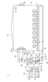
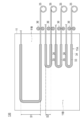
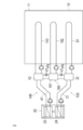
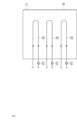
- FIG. 1 It is a systematic diagram which shows the poultry farming system which concerns on 2nd Embodiment, Comprising: A 1st medium and a 2nd medium are mixed, and it is a figure which shows a mode at the time of making the floor surface of a poultry house predetermined temperature. It is a systematic diagram showing a part of heating unit of a poultry farming system concerning modification 1. It is a schematic systematic diagram which shows the poultry farming system which concerns on the modification 2. FIG. It is a schematic systematic diagram which shows a part of the poultry farming system which concerns on the modification 3. FIG.
- FIGS. 1 to 3 A first embodiment of the present invention will be described with reference to FIGS. 1 to 3.
- the same elements will be denoted by the same reference symbols, without redundant description.
- the dimensional proportions of the drawings are exaggerated for the convenience of the description, and may differ from the actual proportions.
- a poultry farming system for raising chickens will be described as an example of a livestock barn system.
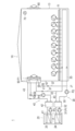
- FIG. 1 is a system diagram showing a poultry farming system (livestock system) 1 according to the first embodiment.
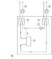
- FIG. 2 is a systematic diagram which shows the heat pump 20 of the poultry farming system 1 which concerns on 1st Embodiment.
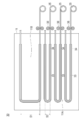
- FIG. 3 is a system diagram showing a part of the heating unit 30 of the poultry farming system 1 according to the first embodiment, as viewed from above. In FIG. 3, the heating unit 30 is shown by a solid line for easy understanding.
- the poultry farming system cools the chicken house 10, a heat pump 20 capable of simultaneously extracting cold heat and heat, a heating unit 30 for heating the inside of the chicken house 10, and a chicken house 10. It has cooling unit 40, adjustment part 50 which adjusts temperature and humidity in chicken house 10, exhaust fan 60 which exhausts air in chicken house 10, and sterilizer 70 which sterilizes chicken house 10 inside.
- Chicken house 10 has floor surface 11, left side wall 12, and right side wall 13 as shown in FIG.
- a bedding straw laying material
- a second pipe 33 described later is disposed below the floor surface 11.
- the adjustment unit 50 is attached to the left side wall 12. Further, an exhaust fan 60 is attached to the right side wall 13.
- the heat pump 20 is configured to be able to simultaneously take cold heat and heat. Further, the heat pump 20 is configured to be able to take out only heat or only cold together with a heating tank 32 and a cooling tank 42 which will be described later. Since the heat pump 20 is an electric type, it does not use fire and there is no need to worry about fire. Hereinafter, the configuration of the heat pump 20 will be described in detail with reference to FIG.
- the heat pump 20 includes a refrigerant flow path 21 through which the refrigerant circulates, a compressor 22 that compresses the refrigerant, an expansion valve 23 that expands the refrigerant, and a first medium that circulates in the heating unit 30 ( And a cold heat exchanger 25 for supplying cold heat to the second medium circulating in the cooling unit 40.
- the refrigerant circulating through the refrigerant channel 21 is not particularly limited, but carbon dioxide can be used, for example.
- the compressor 22 is provided in the refrigerant channel 21. Although the compressor 22 is not particularly limited, for example, a CO 2 compressor can be used. The compression of the refrigerant as it passes through the compressor 22 raises the temperature of the refrigerant.
- the expansion valve 23 is provided in the refrigerant channel 21.
- the expansion valve 23 reduces the temperature of the refrigerant by being expanded when the refrigerant passes through the expansion valve 23.
- the heat exchanger 24 is disposed between the compressor 22 and the expansion valve 23.
- the heat-to-heat heat exchanger 24 heats the first medium circulating in the heating unit 30 by the high-temperature refrigerant circulating from the compressor 22 toward the expansion valve 23.
- the temperature of the first medium heated by the heat exchanger 24 can be, for example, 65 ° C. or 90 ° C.
- the cold heat exchanger 25 is disposed between the expansion valve 23 and the compressor 22.
- the cold heat exchanger 25 cools the second medium circulating in the cooling unit 40 by the low temperature refrigerant circulating from the expansion valve 23 toward the compressor 22.
- the thermal heat exchanger 24 heats the first medium circulating in the heating unit 30, and the cold heat exchanger 25 circulates in the cooling unit 40. 2 Cool the medium. For this reason, the heat pump 20 is in a state where it is possible to simultaneously take out heat and cold.
- the heating unit 30 heats the inside of the poultry house 10 by circulating the first medium heated by the heat taken out of the heat pump 20.
- the heating unit 30 includes a first pipe 31 receiving heat from the heat heat exchanger 24 and a heating tank 32 in which the first medium receiving heat from the heat heat exchanger 24 is stored.
- a second pipe (corresponding to a pipe) 33 disposed under the floor of the poultry house 10, a positioning portion 34 for positioning and fixing the second pipe 33, and a winding portion 35 capable of winding the second pipe 33.
- a cleaning unit 36 for cleaning the second pipe 33, and a third pipe 37 connected to the adjusting unit 50 via the first pipe 55.
- the circulation of the first medium in the first pipe 31 is performed by the first heating pump P1.
- the circulation of the first medium in the second pipe 33 is performed by the second heating pump P2.
- the first medium circulating in the first pipe 31, the second pipe 33, and the third pipe 37 is not particularly limited, and is, for example, water.
- the first medium which has received the heat from the heat exchanger 24 is circulated inside the first pipe 31 inside the first pipe 31 inside the first pipe 31. Then, in the heating tank 32, the first medium which has received the heat from the heat-to-heat heat exchanger 24 is stored. By storing the first medium in the heating tank 32 in this manner, the first medium can be sent to the second pipe 33 at a desired timing.
- the second pipe 33 is branched to the third pipe 37 at the branch portion J1.
- the third pipe 37 is connected to the first pipe 55 at the switching valve V1.
- the switching valve V ⁇ b> 1 switches on / off the supply of the first medium passing through the third pipe 37 to the adjustment unit 50.
- the outer circumferences of the first pipe 31, the second pipe 33, and the third pipe 37 preferably have corrosion resistance.
- the positioning unit 34 can position the second pipe 33 so that the position of the second pipe 33 can be changed as shown in FIG. 3.
- the positioning unit 34 includes a recess (not shown) in which the second pipe 33 is placed.
- the positioning unit 34 positions the second pipe 33 such that the intervals S1 and S2 between the adjacent second pipes 33 are different from each other.
- the positioning unit 34 positions the second pipe 33 so that the distance from the floor surface 11 is constant.
- the positioning unit 34 also plays a role as a heat shield sheet. According to this configuration, it is possible to save the heat necessary for heating the floor surface 11.
- the winding unit 35 can wind the second pipe 33.
- the winding portion 35 is a drum for storage, and in FIG. 3, the second pipe 33 can be delivered from the winding portion 35 by rotating counterclockwise, and by rotating clockwise. , The second pipe 33 can be recovered. Since the winding portion 35 is provided as described above, the second pipe 33 can be easily recovered and laid easily when it is desired to change the position for raising chickens.
- the cleaning unit 36 is provided adjacent to the winding unit 35.
- the cleaning unit 36 is disposed to abut on the second pipe 33, and removes dust attached to the surface of the second pipe 33 when the second pipe 33 is wound around the winding unit 35. Wash.
- the cooling unit 40 cools the inside of the poultry house 10, as shown in FIG.
- the cooling unit 40 includes a fourth pipe 41 receiving cold heat from the cold heat exchanger 25, a cooling tank 42 storing the second medium receiving cold heat from the cold heat exchanger 25, a controller 50, and a second pipe 56. And a fifth pipe 43 connected via the
- the circulation of the second medium in the fourth pipe 41 is performed by the first cooling pump P3, as shown in FIG.
- the circulation of the second medium in the fifth pipe 43 is performed by the second cooling pump P4.
- the second medium circulating in the fourth pipe 41 and the fifth pipe 43 is not particularly limited, and is, for example, water.
- the temperature of the second medium circulating in the fourth pipe 41 and the fifth pipe 43 is, for example, 7 to 10 ° C.
- a second medium which receives cold heat from the cold heat exchanger 25 circulates. Then, the second medium which has received the cold heat from the cold heat exchanger 25 is stored in the cooling tank 42. Thus, by storing the second medium in the cooling tank 42, the second medium can be sent to the fifth pipe 43 at a desired timing.
- the fifth pipe 43 is connected to the second pipe 56 at the switching valve V2.
- the switching valve V ⁇ b> 2 switches on / off the supply of the second medium passing through the fifth pipe 43 to the adjustment unit 50.
- the outer circumferences of the fourth pipe 41 and the fifth pipe 43 have corrosion resistance.
- the heating unit 30 and the cooling unit 40 are provided, only the heat can be taken out by turning on the second heating pump P2 and turning off the second cooling pump P4.
- only the cold heat can be taken out by turning off the second heating pump P2 and turning on the second cooling pump P4.
- the adjustment unit 50 adjusts the temperature and humidity in the poultry house 10.
- the adjustment unit 50 is disposed in the first pipe 55 and the second pipe 56.
- a fan F1 is disposed next to the adjustment unit 50.
- the switching valve V1 turns on the supply of the first medium passing through the third pipe 37 to the adjusting unit 50, and the switching valve V2 cools it.
- the supply of the second medium passing through the fifth pipe 43 of the unit 40 to the adjustment unit 50 is turned off.
- the supply of the first medium passing through the third pipe 37 to the adjustment unit 50 is turned off in the switching valve V1, and in the switching valve V2.
- the supply of the second medium passing through the fifth pipe 43 of the cooling unit 40 to the adjustment unit 50 is turned on.
- the supply of the first medium passing through the third pipe 37 to the adjustment unit 50 is turned off in the switching valve V1, and the cooling unit in the switching valve V2.
- the supply of the second medium passing through the forty-fifth pipe 43 to the adjustment unit 50 is turned on.
- the air in the vicinity of the adjustment unit 50 is cooled by the second medium, and the moisture is converted into water droplets to be condensed and eliminated, whereby the dried air is released to perform dehumidification.
- the supply of the first medium passing through the third pipe 37 to the adjusting unit 50 is turned off in the switching valve V1, and the cooling in the switching valve V2 is performed.
- the supply of the second medium passing through the fifth pipe 43 of the unit 40 to the adjustment unit 50 is turned off.
- the sterilizer 70 is provided in the chicken house 10 and sterilizes the chicken house 10.
- an excimer lamp can be used, for example.
- ozone and radicals having good diffusibility are generated to suppress sterilization and the growth of viruses, and the deodorizing effect on odor and ammonia can be enhanced. Therefore, it is possible to safely promote the growth of the young chick by realizing a comfortable environment.
- the inside of the poultry house 10 a high temperature environment so as to be able to cope with a rapid drop in the outside air temperature.
- the first medium that has received the heat from the heat-to-heat heat exchanger 24 circulates, and the first medium that receives the heat is stored in the heating tank 32.
- the second pipe 33 can warm the inside of the poultry house 10 from below the floor of the poultry house 10.
- the positioning unit 34 positions the second pipe 33 such that the intervals S1 and S2 between the adjacent second pipes 33 are different from each other. For this reason, as shown in FIG. 3, a warm spot 11A and a cool spot 11B can be provided on the floor surface 11 of the poultry house 10. Therefore, chickens can select and move their own warm spot 11A or cool spot 11B.
- the adjustment unit 50 can warm the inside of the poultry house 10.
- the second medium is circulated through the fifth pipe 43 of the cooling unit 40. Then, in the switching valve V1, the supply of the first medium passing through the third pipe 37 to the adjustment unit 50 is turned off, and in the switching valve V2, the second medium passing through the fifth pipe 43 of the cooling unit 40 , Supply to the adjustment unit 50 is turned on. As a result, the adjusting unit 50 can cool the inside of the poultry house 10.
- the above-mentioned summer mode and winter mode are appropriately switched according to the temperature of the day. Moreover, in a humid climate such as rainy season, it is preferable to turn on the dehumidifying function in the adjustment unit 50 to dehumidify the inside of the poultry house 10.
- the first medium when used to heat the chicken house 10, it is preferable to use, for example, 65 ° C. as the temperature of the first medium.
- the first medium when the first medium is subjected to drying in the poultry house 10 in an open house period, for example, 90 ° C. is preferably used as the temperature of the first medium.
- the drying period can be shortened by raising the temperature of the first medium in the vacant period, and the vacant period can be shortened, for example, for 2 days. Therefore, the productivity of the poultry farming system 1 can be improved.
- the poultry farming system 1 is disposed to pass under the floor of the poultry house 10 in which the chicken is fed and the floor of the poultry house 10, and the first medium circulates inside the poultry house 10 And a second pipe 33 for adjusting the temperature of the floor surface 11 of the According to the poultry farming system 1 configured in this manner, the temperature of the floor surface 11 of the poultry house 10 is adjusted by the first medium circulating inside the second pipe 33. For this reason, it is possible to take measures against cold in winter and heat in summer while maintaining the inside of chicken house 10 in a suitable environment and preventing deterioration of the condition of bedding (bed). Furthermore, even when the temperature difference during the daytime is large, the temperature in the poultry house 10 can be suitably adjusted. Therefore, a comfortable chicken house 10 can be provided not only in winter and summer but also throughout the year.
- the second pipe 33 is disposed so that a temperature difference occurs in the floor surface 11.
- the floor 11 of the poultry house 10 can be provided with a warm spot 11A and a cool spot 11B. Therefore, it is possible to provide a poultry farming system 1 in which the chicken can move to the warm spot 11A or the cool spot 11B by himself.
- the poultry farming system 1 further includes a positioning unit 34 that positions the second pipe 33 so that the position of the second pipe 33 can be changed.
- the second pipe 33 can be positioned and fixed so that there is a place where the second pipe 33 is placed and a place where the second pipe 33 is not placed under the floor of the poultry house 10 .
- the floor 11 of the poultry house 10 can be provided with a warm spot 11A and a cool spot 11B.
- the second pipes 33 are disposed such that the intervals S1 and S2 between the adjacent second pipes 33 are different from each other. According to the poultry farming system 1 configured in this manner, the warm spot 11A and the cool spot 11B can be surely provided on the floor surface 11 of the poultry house 10.
- the poultry farming system 1 further includes a winding unit 35 capable of winding the second pipe 33.
- the second pipe 33 can be easily recovered and laid easily.
- the poultry farming system 1 when the 2nd pipe 33 is wound by the winding part 35, the poultry farming system 1 further has the washing
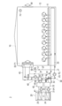
- FIG. 4 is a block diagram showing a poultry farming system 2 according to a second embodiment, and is a view showing a state when floor heating is performed.
- FIG. 5 is a block diagram showing a poultry farming system 2 according to a second embodiment, and is a view showing a state when floor cooling is performed.
- FIG. 6 is a system diagram showing the poultry farming system 2 according to the second embodiment, and shows a state in which the first medium and the second medium are mixed to bring the floor surface 11 of the poultry house 10 to a predetermined temperature.
- FIG. Descriptions of parts in common with the first embodiment will be omitted, and parts characterized only in the second embodiment will be described.
- the same members as those in the first embodiment described above are denoted by the same reference numerals, and redundant description will be omitted.
- the first medium stored in the heating tank 32 and the second medium stored in the cooling tank 42 can be mixed as compared with the chicken farming system 1 according to the first embodiment. It differs in the point which is constituted.
- the poultry farming system 2 includes a chicken house 10 in which chickens are fed, a heat pump 20 capable of simultaneously extracting cold and heat, a heating unit 30 for heating the inside of the chicken house 10, and a chicken house 10.
- a first bypass 81 for circulating the first medium at 33 and a second bypass 82 and a third bypass 83 connecting the second pipe 33 and the fifth pipe 43 are provided.
- the configuration of the chicken house 10, the heat pump 20, the heating unit 30, the cooling unit 40, the adjustment unit 50, the exhaust fan 60, and the sterilizer 70 is the same as the configuration of the poultry system 1 according to the first embodiment described above. Is omitted. That is, the chicken breeding system 2 according to the second embodiment further includes a first bypass 81, a second bypass 82, and a third bypass 83 in addition to the chicken breeding system 1 according to the first embodiment.
- the first bypass 81 is provided to circulate the first medium in the second pipe 33, as shown in FIG.
- a three-way valve V4 is disposed at a position where the first bypass 81 is connected to the second pipe 33 (a connection position on the left side of FIG. 4).
- the first medium circulated in the second pipe 33 returns to the second pipe 33 via the first bypass 81 and the three-way valve V4.
- a three-way valve V5 is disposed at a position where the second bypass 82 is connected to the second pipe 33.
- a three-way valve V6 is disposed at a point where the third bypass 83 is connected to the second pipe 33.
- the inside of the poultry house 10 a high temperature environment so as to be able to cope with a rapid drop in the outside air temperature.
- the second heating pump P2 is turned on and the second cooling pump P4 is turned off, and the three-way valves V4, V5 and V6 are adjusted to make only the first medium in the second pipe 33 Circulate.
- the floor surface 11 of the poultry house 10 is warmed by floor heating.
- the second heating pump P2 is turned off and the second cooling pump P4 is turned on, and the three-way valves V4, V5 and V6 are adjusted to make only the second medium 33 into the second pipe 33. Circulate.
- the floor surface 11 of the poultry house 10 is cooled by floor cooling.
- the second medium stored in the cooling tank 42 includes the fifth pipe 43, the second bypass 82, the three-way valve V5, the second pipe 33, the three-way valve V6, the third bypass 83, and the fifth pipe 43 in this order. Circulate.
- the temperature of the floor surface 11 of the poultry house 10 is set to a predetermined temperature according to the temperature of the day in the middle of the spring or fall.
- the second heating pump P2 is turned on, the second cooling pump P4 is turned on, and the three-way valves V4, V5, V6 are adjusted to make the second medium 33 the first medium.
- the mixed medium of the second medium are circulated.
- the floor surface 11 of the poultry house 10 can be set to a predetermined desired temperature.
- the amount of the second medium flowing into the second pipe 33 can be adjusted by adjusting the three-way valves V5 and V6. As a result, the temperature of the mixed medium can be adjusted.
- the poultry farming system 2 further includes the heat pump 20 capable of simultaneously extracting cold energy and warm energy, and the second medium cooled by the cold energy circulates the inside of the second pipe 33
- the floor surface 11 of the poultry house 10 is thereby cooled.
- floor cooling can be performed. Therefore, it is possible to actively cool the vicinity of the body height of the chicken and efficiently create a comfortable space with less energy than cooling the entire chicken house 10 with an air conditioner.
- the floor surface 11 of the poultry house 10 is brought to a predetermined temperature by circulating the mixed medium in which the second medium cooled by cold heat and the first medium heated by heat are mixed in the second pipe 33. . According to this configuration, it is possible to keep the condition of the bedding (bed) and the air in the poultry house 10 good. Furthermore, in order to freely control the temperature of the floor surface 11, when it is desired to lower the temperature, it is not the conventional natural heat radiation but by adjusting the mixed medium to the required temperature and supplying it, the rapid temperature change of the external environment Can follow without time lag.
- FIG. 7 is a system diagram showing a part of the heating unit 130 of the poultry farming system according to the first modification.
- the positioning unit 34 positions the second pipe 33 such that the intervals S1 and S2 between the adjacent second pipes 33 are different from each other.
- the positioning portion 34 is configured such that the second pipe 33 has a variable length in the intervals S1 and S2 and a partial length in the lateral direction of the second pipe 33. May be positioned.
- a warm spot 11A and a cool spot 11B are formed on the floor surface 11 of the poultry house 10, and the cool spot 11B can be formed in a wider range.
- FIG. 8 is a schematic diagram showing a poultry farming system 3 according to a second modification.
- the poultry farming system 3 includes a poultry house 10, a heat pump 20, a heating unit 130, a cooling unit 140, an adjustment unit 50, an exhaust fan 60, and a sterilizer 70. And a mixing unit 180.
- the configuration of the chicken house 10, the heat pump 20, the adjustment unit 50, the exhaust fan 60, and the sterilizer 70 is the same as that of the above-described embodiment, and thus the description thereof is omitted.
- the heating unit 130 includes a first pipe 31 receiving heat from the heat heat exchanger 24, a heating tank 32 storing the first medium receiving heat from the heat heat exchanger 24, and a chicken house And a second pipe 33 disposed under the floor of 10.
- the cooling unit 140 includes a fourth pipe 41 receiving cold heat from the cold heat heat exchanger 25, a cooling tank 42 in which a second medium receiving cold heat from the cold heat heat exchanger 25, and And a sixth pipe 143 disposed under the floor of 10. The circulation of the second medium in the sixth pipe 143 is performed by the third cooling pump P5.
- the mixing unit 180 mixes the first medium stored in the heating tank 32 and the second medium stored in the cooling tank 42 to produce a third medium.
- the mixing unit 180 has a mixing tank 181 continuous with the heating tank 32 and the cooling tank 42, and a seventh pipe 182 disposed below the floor of the poultry house 10. The circulation of the third medium in the seventh pipe 182 is performed by the pump P6.
- the heating tank 32 and the mixing tank 181 and the cooling tank 42 and the mixing tank 181 are connected via a valve V3.
- the amount of the first medium supplied from the heating tank 32 to the mixing tank 181 can be adjusted by the opening degree of the valve V3. Further, the amount of the second medium supplied from the cooling tank 42 to the mixing tank 181 can be adjusted by the opening degree of the valve V3.
- the floor surface 11 is in the order of the place where the second pipe 33 is placed, the place where the seventh pipe 182 is placed, and the place where the sixth pipe 143 is placed. Temperature can be raised. Therefore, the chicken can move to a warm place or a cool place by himself.
- the media flowing through the second pipe 33, the seventh pipe 182, and the sixth pipe 143 have different temperatures from one another.
- the temperature of the media flowing through the second pipe 33 and the seventh pipe 182 is The temperatures of the media flowing through the seventh pipe 182 and the sixth pipe 143 may be the same.
- FIG. 9 is a schematic diagram showing a part of a poultry farming system 4 according to a third modification.
- the poultry farming system 4 according to the modification 3 is provided in each of a plurality of (three in FIG. 9) second pipes 33 and a plurality of second pipes 33 as shown in FIG. And a control valve V7 capable of adjusting the flow rate of the first medium.
- the heated first medium circulates through the plurality of second pipes 33.
- the temperature of the floor surface 11 can be obtained by providing an appropriate difference between the flow rates of the first medium flowing through the plurality of second pipes 33 by the adjusting valve V7. Can make a difference.
- the present invention is applied to a poultry farming system that breeds chickens as a livestock house system, but can also be applied to breeding of pigs and the like.
- the positioning unit 34 positions the second pipe 33 so that the distance from the floor surface 11 is constant.
- the positioning unit 34 may position the second pipe 33 so that the distance from the floor surface 11 differs depending on the place. According to this configuration, it is possible to generate a temperature gradient on the floor surface 11 according to the depth from the floor surface 11. Thus, the chicken can move to a place where the temperature environment is more favorable.
- the heating unit 30 includes the heating tank 32, and the cooling unit 40 includes the cooling tank 42.
- the heating unit may not include the heating tank, and the cooling unit may not include the cooling tank.
- a radiator for exhausting the cold heat and the warm heat extracted from the heat pump is provided.
- the supply of the first medium to the adjustment unit 50 is turned off, and the supply of the second medium to the adjustment unit 50 is turned on. I made it.
- the supply of the first medium to the adjustment unit 50 may be turned on, and the supply of the second medium to the adjustment unit 50 may be turned on.
- the dehumidifying mode has been described using a so-called compressor system that dehumidifies using condensation generated by cooling air.
- it may be dehumidified by a so-called desiccant method of dehumidifying by adsorbing the moisture to the desiccant.
- the three-way valve V4 is provided at a place where the first bypass 81 is connected to the second pipe 33, and the three-way valve V5 is provided at a place where the second bypass 82 is connected to the second pipe 33.
- a three-way valve V6 is provided at a position where the third bypass 83 is connected to the second pipe 33.
- the valves located at each point may be two-way valves.
- Poultry system Livestock system
Landscapes
- Life Sciences & Earth Sciences (AREA)
- Environmental Sciences (AREA)
- Engineering & Computer Science (AREA)
- Zoology (AREA)
- Animal Husbandry (AREA)
- Biodiversity & Conservation Biology (AREA)
- Thermal Sciences (AREA)
- Chemical & Material Sciences (AREA)
- Physics & Mathematics (AREA)
- Combustion & Propulsion (AREA)
- Mechanical Engineering (AREA)
- General Engineering & Computer Science (AREA)
- Housing For Livestock And Birds (AREA)
Abstract
Description
本発明の第1実施形態を、図1~図3を参照しつつ説明する。なお、図面の説明において同一の要素には同一の符号を付し、重複する説明を省略する。図面の寸法比率は、説明の都合上誇張されており、実際の比率とは異なる場合がある。
次に、図4~図6を参照して、第2実施形態に係る養鶏システム2について説明する。図4は、第2実施形態に係る養鶏システム2を示す系統図であって、床暖房する際の様子を示す図である。図5は、第2実施形態に係る養鶏システム2を示す系統図であって、床冷房する際の様子を示す図である。図6は、第2実施形態に係る養鶏システム2を示す系統図であって、第1媒体および第2媒体を混合して、鶏舎10の床面11を所定の温度にする際の様子を示す図である。第1実施形態と共通する部分は説明を省略し、第2実施形態のみに特徴のある箇所について説明する。なお、上述した第1実施形態と同一の部材には同一の符号を付して説明し、重複した説明は省略する。第2実施形態に係る養鶏システム2は、第1実施形態に係る養鶏システム1と比較して、加熱タンク32に貯蔵される第1媒体および冷却タンク42に貯蔵される第2媒体が混合可能に構成されている点について異なる。
次に、図7を参照して、変形例1に係る養鶏システムの構成について説明する。図7は、変形例1に係る養鶏システムの加熱ユニット130の一部を示す系統図である。
次に、図8を参照して、変形例2に係る養鶏システム3の構成について説明する。図8は、変形例2に係る養鶏システム3を示す概略系統図である。
次に、図9を参照して、変形例3に係る養鶏システム4の構成について説明する。図9は、変形例3に係る養鶏システム4の一部を示す概略系統図である。
10 鶏舎、
11 床面、
20 ヒートポンプ、
31 第1パイプ、
32 加熱タンク、
33 第2パイプ(パイプ)、
34 位置決め部、
35 巻回部、
36 洗浄部、
S1、S2 第1パイプ間の間隔。
Claims (7)
- 家畜が養育される家畜舎と、
前記家畜舎の床下を通過するように配置され、内部を媒体が循環することによって前記家畜舎の床面の温度を調整するパイプと、を有する家畜舎システム。 - 冷熱および温熱を同時に取り出し可能なヒートポンプをさらに有し、
前記パイプの前記内部を前記冷熱によって冷却された前記媒体が循環することによって、前記家畜舎の床面が冷却される、請求項1に記載の家畜舎システム。 - 前記パイプの前記内部を、前記冷熱によって冷却された冷却媒体および前記温熱によって加熱された加熱媒体が混合した混合媒体が循環することによって、前記家畜舎の床面を所定の温度にする、請求項2に記載の家畜舎システム。
- 前記パイプは、前記床面に温度差が生じるように配設されている、請求項1~3のいずれか1項に記載の家畜舎システム。
- 前記パイプは、隣り合う前記パイプ間の間隔が互いに異なるように、配設されている、請求項4に記載の家畜舎システム。
- 前記パイプは複数設けられ、
少なくとも2つの前記パイプを循環する前記媒体の温度は、互いに異なる請求項1~5のいずれか1項に記載の家畜舎システム。 - 前記パイプは複数設けられ、
複数の前記パイプのそれぞれに設けられ、複数の前記パイプにおける前記媒体の流量を調整可能な調整弁をさらに有する、請求項1~6のいずれか1項に記載の家畜舎システム。
Priority Applications (4)
| Application Number | Priority Date | Filing Date | Title |
|---|---|---|---|
| JP2019550474A JP6989614B2 (ja) | 2017-11-01 | 2018-10-31 | 家畜舎システム |
| US16/756,505 US20200281152A1 (en) | 2017-11-01 | 2018-10-31 | Livestock stall system |
| BR112020008699-1A BR112020008699A2 (pt) | 2017-11-01 | 2018-10-31 | sistema de baias para criação de aves |
| RU2020115162A RU2748946C1 (ru) | 2017-11-01 | 2018-10-31 | Система стойлового содержания скота |
Applications Claiming Priority (2)
| Application Number | Priority Date | Filing Date | Title |
|---|---|---|---|
| JPPCT/JP2017/039586 | 2017-11-01 | ||
| PCT/JP2017/039586 WO2019087334A1 (ja) | 2017-11-01 | 2017-11-01 | 家畜舎システム |
Publications (1)
| Publication Number | Publication Date |
|---|---|
| WO2019088202A1 true WO2019088202A1 (ja) | 2019-05-09 |
Family
ID=66331602
Family Applications (2)
| Application Number | Title | Priority Date | Filing Date |
|---|---|---|---|
| PCT/JP2017/039586 Ceased WO2019087334A1 (ja) | 2017-11-01 | 2017-11-01 | 家畜舎システム |
| PCT/JP2018/040585 Ceased WO2019088202A1 (ja) | 2017-11-01 | 2018-10-31 | 家畜舎システム |
Family Applications Before (1)
| Application Number | Title | Priority Date | Filing Date |
|---|---|---|---|
| PCT/JP2017/039586 Ceased WO2019087334A1 (ja) | 2017-11-01 | 2017-11-01 | 家畜舎システム |
Country Status (5)
| Country | Link |
|---|---|
| US (1) | US20200281152A1 (ja) |
| JP (1) | JP6989614B2 (ja) |
| BR (1) | BR112020008699A2 (ja) |
| RU (1) | RU2748946C1 (ja) |
| WO (2) | WO2019087334A1 (ja) |
Cited By (2)
| Publication number | Priority date | Publication date | Assignee | Title |
|---|---|---|---|---|
| EP3785531A1 (en) * | 2019-08-26 | 2021-03-03 | Yuanhu Cheng | Livestock central air conditioner and livestock house |
| JP2022030824A (ja) * | 2020-08-07 | 2022-02-18 | 株式会社エアロ・ピュア | 畜舎の空気調和システム |
Families Citing this family (6)
| Publication number | Priority date | Publication date | Assignee | Title |
|---|---|---|---|---|
| US11369081B2 (en) * | 2020-11-06 | 2022-06-28 | The Heated Dog House | Protective enclosure for an animal and method of making |
| CN114667935B (zh) * | 2022-03-22 | 2023-04-28 | 西藏自治区农牧科学院畜牧兽医研究所 | 一种用于提高牦牛泌乳养殖舍温控系统及方法 |
| BE1030649B1 (nl) * | 2022-06-20 | 2024-01-30 | Dave Vandenbrande | Restwarmte opvang van biologische organisme om gas/vloeistof opwarming te bekomen |
| US20240255190A1 (en) * | 2023-01-28 | 2024-08-01 | Visionergy, LLC | Systems and methods for utilizing geothermal cooling to cool open air structures |
| CN117814122B (zh) * | 2024-01-08 | 2025-12-19 | 华中农业大学 | 一种养殖场供暖方法和系统 |
| CN117717007A (zh) * | 2024-01-29 | 2024-03-19 | 张耀辰 | 牲畜养殖工厂和在牲畜养殖工厂中养殖牲畜的方法 |
Citations (8)
| Publication number | Priority date | Publication date | Assignee | Title |
|---|---|---|---|---|
| JPS4859670U (ja) * | 1971-11-06 | 1973-07-28 | ||
| JPS5344377A (en) * | 1976-10-04 | 1978-04-21 | Furukawa Electric Co Ltd:The | Apparatus for heating floor of breeding animals |
| JPH05276847A (ja) * | 1992-01-07 | 1993-10-26 | Nashat N Helmy | 温度制御畜房用フローリング構成体、畜房内の家畜の挙動反応誘起方法及び畜房の温度制御システム |
| JPH0595278U (ja) * | 1992-06-03 | 1993-12-27 | ダイワ精工株式会社 | 魚釣用リ−ル |
| JPH0968368A (ja) * | 1995-08-31 | 1997-03-11 | Matsushita Electric Works Ltd | 給湯・空調システム |
| JP2005009701A (ja) * | 2003-06-17 | 2005-01-13 | Yukio Inoguchi | 床暖房システム |
| JP2012083049A (ja) * | 2010-10-13 | 2012-04-26 | Daikin Industries Ltd | 暖房装置 |
| WO2017029819A1 (ja) * | 2015-08-17 | 2017-02-23 | 三菱電機株式会社 | 熱利用装置 |
Family Cites Families (10)
| Publication number | Priority date | Publication date | Assignee | Title |
|---|---|---|---|---|
| JPS6144117U (ja) * | 1984-08-27 | 1986-03-24 | 東京瓦斯株式会社 | 放熱装置 |
| JPH02100114U (ja) * | 1989-01-26 | 1990-08-09 | ||
| JPH0719255Y2 (ja) * | 1989-07-20 | 1995-05-10 | 有限会社ミナギ技研 | 分娩豚房 |
| JPH0595268U (ja) * | 1992-06-01 | 1993-12-27 | 株式会社セキネ | 簀の子状分娩豚房床 |
| JP3763906B2 (ja) * | 1996-10-23 | 2006-04-05 | 株式会社ガスター | 温度調節装置 |
| JPH10267300A (ja) * | 1997-03-26 | 1998-10-09 | Tokyo Gas Co Ltd | 床暖房用パネルユニット及びそれを用いた床暖房用パネル |
| JPH10286038A (ja) * | 1997-04-15 | 1998-10-27 | Aisin Seiki Co Ltd | 動物用冷暖房装置 |
| JPH11142071A (ja) * | 1997-11-13 | 1999-05-28 | Toyox Co Ltd | パイプユニット |
| RU69703U1 (ru) * | 2007-04-11 | 2008-01-10 | Государственное образовательное учреждение высшего профессионального образования "Томский государственный архитектурно-строительный университет" (ГОУВПО "ТГАСУ") | Тепловая секция родильного отделения свинокомплекса |
| KR20120041828A (ko) * | 2010-08-27 | 2012-05-03 | 주식회사 에이케이 | 냉?온수 배관 파이프를 부설한 고상식 가금류 위생사육시설구조 |
-
2017
- 2017-11-01 WO PCT/JP2017/039586 patent/WO2019087334A1/ja not_active Ceased
-
2018
- 2018-10-31 US US16/756,505 patent/US20200281152A1/en not_active Abandoned
- 2018-10-31 WO PCT/JP2018/040585 patent/WO2019088202A1/ja not_active Ceased
- 2018-10-31 RU RU2020115162A patent/RU2748946C1/ru active
- 2018-10-31 JP JP2019550474A patent/JP6989614B2/ja active Active
- 2018-10-31 BR BR112020008699-1A patent/BR112020008699A2/pt not_active Application Discontinuation
Patent Citations (8)
| Publication number | Priority date | Publication date | Assignee | Title |
|---|---|---|---|---|
| JPS4859670U (ja) * | 1971-11-06 | 1973-07-28 | ||
| JPS5344377A (en) * | 1976-10-04 | 1978-04-21 | Furukawa Electric Co Ltd:The | Apparatus for heating floor of breeding animals |
| JPH05276847A (ja) * | 1992-01-07 | 1993-10-26 | Nashat N Helmy | 温度制御畜房用フローリング構成体、畜房内の家畜の挙動反応誘起方法及び畜房の温度制御システム |
| JPH0595278U (ja) * | 1992-06-03 | 1993-12-27 | ダイワ精工株式会社 | 魚釣用リ−ル |
| JPH0968368A (ja) * | 1995-08-31 | 1997-03-11 | Matsushita Electric Works Ltd | 給湯・空調システム |
| JP2005009701A (ja) * | 2003-06-17 | 2005-01-13 | Yukio Inoguchi | 床暖房システム |
| JP2012083049A (ja) * | 2010-10-13 | 2012-04-26 | Daikin Industries Ltd | 暖房装置 |
| WO2017029819A1 (ja) * | 2015-08-17 | 2017-02-23 | 三菱電機株式会社 | 熱利用装置 |
Cited By (2)
| Publication number | Priority date | Publication date | Assignee | Title |
|---|---|---|---|---|
| EP3785531A1 (en) * | 2019-08-26 | 2021-03-03 | Yuanhu Cheng | Livestock central air conditioner and livestock house |
| JP2022030824A (ja) * | 2020-08-07 | 2022-02-18 | 株式会社エアロ・ピュア | 畜舎の空気調和システム |
Also Published As
| Publication number | Publication date |
|---|---|
| WO2019087334A1 (ja) | 2019-05-09 |
| RU2748946C1 (ru) | 2021-06-02 |
| JPWO2019088202A1 (ja) | 2020-11-12 |
| US20200281152A1 (en) | 2020-09-10 |
| JP6989614B2 (ja) | 2022-01-05 |
| BR112020008699A2 (pt) | 2020-10-27 |
Similar Documents
| Publication | Publication Date | Title |
|---|---|---|
| JP6989614B2 (ja) | 家畜舎システム | |
| WO2019087335A1 (ja) | 家畜舎システム | |
| JP7245781B2 (ja) | 家畜舎システム | |
| KR101790015B1 (ko) | 축사 냉난방 및 냉온음용수 급수 병행 시스템 | |
| NL1038219C2 (en) | Arrangement for even distribution of gaseous material in a spatial area. | |
| KR102091191B1 (ko) | 건물 온도 및 악취 관리를 위한 온도조절 환기시스템 | |
| JP6548338B2 (ja) | 家畜舎システム | |
| KR101680985B1 (ko) | 착탈식 히팅장치를 구비한 시설하우스용 제습기 | |
| JP2002051657A (ja) | 牛体冷房装置 | |
| JP2020074758A (ja) | 園芸用施設の除湿システム | |
| CN210094279U (zh) | 家禽养殖专用除湿机 | |
| KR101677052B1 (ko) | 열회수 환기장치 및 열회수 환기방법 | |
| CN104381139B (zh) | 一种带调温装置的猪舍 | |
| JP7798701B2 (ja) | 二酸化炭素含有ガス供給システム及び二酸化炭素含有ガス供給方法 | |
| JP3993940B2 (ja) | 植物工場における空調システム及びその装置 | |
| KR20150137567A (ko) | 축열식 공기소독 냉열 교환기 | |
| JP6746069B2 (ja) | 植物栽培施設 | |
| US20220378007A1 (en) | Livestock house air filtration system | |
| KR101176303B1 (ko) | 농축산용 온풍난방형 열회수형 환기장치 | |
| CN220326480U (zh) | 一种牛养殖用牛舍通风装置 | |
| Bray et al. | Environmental temperatures in a tunnel ventilated barn and in an air conditioned barn in Florida | |
| KR20250066082A (ko) | 돈사와 온실의 자원 순환을 위한 돈사-온실 통합시스템 | |
| KR100690078B1 (ko) | 농축산용 냉난방장치 | |
| Bray et al. | Latest on tunnel barns for cow comfort | |
| Bleizgys et al. | The problems of microclimate in lithuanian cowsheds |
Legal Events
| Date | Code | Title | Description |
|---|---|---|---|
| 121 | Ep: the epo has been informed by wipo that ep was designated in this application |
Ref document number: 18873451 Country of ref document: EP Kind code of ref document: A1 |
|
| ENP | Entry into the national phase |
Ref document number: 2019550474 Country of ref document: JP Kind code of ref document: A |
|
| NENP | Non-entry into the national phase |
Ref country code: DE |
|
| REG | Reference to national code |
Ref country code: BR Ref legal event code: B01A Ref document number: 112020008699 Country of ref document: BR |
|
| ENP | Entry into the national phase |
Ref document number: 112020008699 Country of ref document: BR Kind code of ref document: A2 Effective date: 20200430 |
|
| 122 | Ep: pct application non-entry in european phase |
Ref document number: 18873451 Country of ref document: EP Kind code of ref document: A1 |