WO2019087890A1 - ティルティングパッド軸受 - Google Patents
ティルティングパッド軸受 Download PDFInfo
- Publication number
- WO2019087890A1 WO2019087890A1 PCT/JP2018/039459 JP2018039459W WO2019087890A1 WO 2019087890 A1 WO2019087890 A1 WO 2019087890A1 JP 2018039459 W JP2018039459 W JP 2018039459W WO 2019087890 A1 WO2019087890 A1 WO 2019087890A1
- Authority
- WO
- WIPO (PCT)
- Prior art keywords
- pad
- recess
- liner
- axis
- bearing
- Prior art date
- Legal status (The legal status is an assumption and is not a legal conclusion. Google has not performed a legal analysis and makes no representation as to the accuracy of the status listed.)
- Ceased
Links
Images


Classifications
-
- F—MECHANICAL ENGINEERING; LIGHTING; HEATING; WEAPONS; BLASTING
- F16—ENGINEERING ELEMENTS AND UNITS; GENERAL MEASURES FOR PRODUCING AND MAINTAINING EFFECTIVE FUNCTIONING OF MACHINES OR INSTALLATIONS; THERMAL INSULATION IN GENERAL
- F16C—SHAFTS; FLEXIBLE SHAFTS; ELEMENTS OR CRANKSHAFT MECHANISMS; ROTARY BODIES OTHER THAN GEARING ELEMENTS; BEARINGS
- F16C17/00—Sliding-contact bearings for exclusively rotary movement
- F16C17/04—Sliding-contact bearings for exclusively rotary movement for axial load only
- F16C17/06—Sliding-contact bearings for exclusively rotary movement for axial load only with tiltably-supported segments, e.g. Michell bearings
-
- F—MECHANICAL ENGINEERING; LIGHTING; HEATING; WEAPONS; BLASTING
- F16—ENGINEERING ELEMENTS AND UNITS; GENERAL MEASURES FOR PRODUCING AND MAINTAINING EFFECTIVE FUNCTIONING OF MACHINES OR INSTALLATIONS; THERMAL INSULATION IN GENERAL
- F16C—SHAFTS; FLEXIBLE SHAFTS; ELEMENTS OR CRANKSHAFT MECHANISMS; ROTARY BODIES OTHER THAN GEARING ELEMENTS; BEARINGS
- F16C17/00—Sliding-contact bearings for exclusively rotary movement
- F16C17/02—Sliding-contact bearings for exclusively rotary movement for radial load only
- F16C17/03—Sliding-contact bearings for exclusively rotary movement for radial load only with tiltably-supported segments, e.g. Michell bearings
-
- F—MECHANICAL ENGINEERING; LIGHTING; HEATING; WEAPONS; BLASTING
- F16—ENGINEERING ELEMENTS AND UNITS; GENERAL MEASURES FOR PRODUCING AND MAINTAINING EFFECTIVE FUNCTIONING OF MACHINES OR INSTALLATIONS; THERMAL INSULATION IN GENERAL
- F16C—SHAFTS; FLEXIBLE SHAFTS; ELEMENTS OR CRANKSHAFT MECHANISMS; ROTARY BODIES OTHER THAN GEARING ELEMENTS; BEARINGS
- F16C17/00—Sliding-contact bearings for exclusively rotary movement
- F16C17/10—Sliding-contact bearings for exclusively rotary movement for both radial and axial load
-
- F—MECHANICAL ENGINEERING; LIGHTING; HEATING; WEAPONS; BLASTING
- F16—ENGINEERING ELEMENTS AND UNITS; GENERAL MEASURES FOR PRODUCING AND MAINTAINING EFFECTIVE FUNCTIONING OF MACHINES OR INSTALLATIONS; THERMAL INSULATION IN GENERAL
- F16C—SHAFTS; FLEXIBLE SHAFTS; ELEMENTS OR CRANKSHAFT MECHANISMS; ROTARY BODIES OTHER THAN GEARING ELEMENTS; BEARINGS
- F16C17/00—Sliding-contact bearings for exclusively rotary movement
- F16C17/12—Sliding-contact bearings for exclusively rotary movement characterised by features not related to the direction of the load
- F16C17/24—Sliding-contact bearings for exclusively rotary movement characterised by features not related to the direction of the load with devices affected by abnormal or undesired positions, e.g. for preventing overheating, for safety
- F16C17/243—Sliding-contact bearings for exclusively rotary movement characterised by features not related to the direction of the load with devices affected by abnormal or undesired positions, e.g. for preventing overheating, for safety related to temperature and heat, e.g. for preventing overheating
-
- F—MECHANICAL ENGINEERING; LIGHTING; HEATING; WEAPONS; BLASTING
- F16—ENGINEERING ELEMENTS AND UNITS; GENERAL MEASURES FOR PRODUCING AND MAINTAINING EFFECTIVE FUNCTIONING OF MACHINES OR INSTALLATIONS; THERMAL INSULATION IN GENERAL
- F16C—SHAFTS; FLEXIBLE SHAFTS; ELEMENTS OR CRANKSHAFT MECHANISMS; ROTARY BODIES OTHER THAN GEARING ELEMENTS; BEARINGS
- F16C27/00—Elastic or yielding bearings or bearing supports, for exclusively rotary movement
- F16C27/02—Sliding-contact bearings
-
- F—MECHANICAL ENGINEERING; LIGHTING; HEATING; WEAPONS; BLASTING
- F16—ENGINEERING ELEMENTS AND UNITS; GENERAL MEASURES FOR PRODUCING AND MAINTAINING EFFECTIVE FUNCTIONING OF MACHINES OR INSTALLATIONS; THERMAL INSULATION IN GENERAL
- F16C—SHAFTS; FLEXIBLE SHAFTS; ELEMENTS OR CRANKSHAFT MECHANISMS; ROTARY BODIES OTHER THAN GEARING ELEMENTS; BEARINGS
- F16C33/00—Parts of bearings; Special methods for making bearings or parts thereof
- F16C33/02—Parts of sliding-contact bearings
- F16C33/04—Brasses; Bushes; Linings
- F16C33/06—Sliding surface mainly made of metal
- F16C33/10—Construction relative to lubrication
- F16C33/1025—Construction relative to lubrication with liquid, e.g. oil, as lubricant
- F16C33/106—Details of distribution or circulation inside the bearings, e.g. details of the bearing surfaces to affect flow or pressure of the liquid
- F16C33/1075—Wedges, e.g. ramps or lobes, for generating pressure
-
- F—MECHANICAL ENGINEERING; LIGHTING; HEATING; WEAPONS; BLASTING
- F16—ENGINEERING ELEMENTS AND UNITS; GENERAL MEASURES FOR PRODUCING AND MAINTAINING EFFECTIVE FUNCTIONING OF MACHINES OR INSTALLATIONS; THERMAL INSULATION IN GENERAL
- F16C—SHAFTS; FLEXIBLE SHAFTS; ELEMENTS OR CRANKSHAFT MECHANISMS; ROTARY BODIES OTHER THAN GEARING ELEMENTS; BEARINGS
- F16C33/00—Parts of bearings; Special methods for making bearings or parts thereof
- F16C33/02—Parts of sliding-contact bearings
- F16C33/04—Brasses; Bushes; Linings
- F16C33/06—Sliding surface mainly made of metal
- F16C33/10—Construction relative to lubrication
- F16C33/1025—Construction relative to lubrication with liquid, e.g. oil, as lubricant
- F16C33/106—Details of distribution or circulation inside the bearings, e.g. details of the bearing surfaces to affect flow or pressure of the liquid
- F16C33/108—Details of distribution or circulation inside the bearings, e.g. details of the bearing surfaces to affect flow or pressure of the liquid with a plurality of elements forming the bearing surfaces, e.g. bearing pads
-
- F—MECHANICAL ENGINEERING; LIGHTING; HEATING; WEAPONS; BLASTING
- F16—ENGINEERING ELEMENTS AND UNITS; GENERAL MEASURES FOR PRODUCING AND MAINTAINING EFFECTIVE FUNCTIONING OF MACHINES OR INSTALLATIONS; THERMAL INSULATION IN GENERAL
- F16C—SHAFTS; FLEXIBLE SHAFTS; ELEMENTS OR CRANKSHAFT MECHANISMS; ROTARY BODIES OTHER THAN GEARING ELEMENTS; BEARINGS
- F16C2360/00—Engines or pumps
- F16C2360/23—Gas turbine engines
-
- F—MECHANICAL ENGINEERING; LIGHTING; HEATING; WEAPONS; BLASTING
- F16—ENGINEERING ELEMENTS AND UNITS; GENERAL MEASURES FOR PRODUCING AND MAINTAINING EFFECTIVE FUNCTIONING OF MACHINES OR INSTALLATIONS; THERMAL INSULATION IN GENERAL
- F16C—SHAFTS; FLEXIBLE SHAFTS; ELEMENTS OR CRANKSHAFT MECHANISMS; ROTARY BODIES OTHER THAN GEARING ELEMENTS; BEARINGS
- F16C33/00—Parts of bearings; Special methods for making bearings or parts thereof
- F16C33/02—Parts of sliding-contact bearings
- F16C33/04—Brasses; Bushes; Linings
- F16C33/06—Sliding surface mainly made of metal
- F16C33/12—Structural composition; Use of special materials or surface treatments, e.g. for rust-proofing
- F16C33/121—Use of special materials
Definitions
- the present invention relates to a tilting pad bearing.
- Priority is claimed on Japanese Patent Application No. 2017-211141, filed Oct. 31, 2017, the content of which is incorporated herein by reference.
- Patent Document 1 describes a journal bearing.
- the journal bearing described in Patent Document 1 supports the rotation shaft by a plurality of pads arranged in the circumferential direction of the rotation shaft. An oil film of lubricating oil is formed between the pad and the outer peripheral surface of the rotating shaft.
- there is one called a tilting pad bearing In the tilting pad bearing, each pad is pivotally supported by a pointed pivot provided on the inner circumferential surface of the housing.
- the present invention has been made in view of the above circumstances, and provides a tilting pad bearing capable of stably supporting a rotating shaft while suppressing an increase in pad temperature and occurrence of local plastic flow. .
- the tilting pad bearing supports the pad disposed so as to face the outer peripheral surface of the rotating shaft, and supports the pad radially outward around the axis of the rotating shaft.
- the liner includes: a liner; and a pivot that supports the pad at a radially outer side about the axis and at a central position in an axial direction of the rotation axis, whereby the pad can swing.
- the surface of the liner facing the pad is at least at the central position, in the direction away from the pad, in one of the surface of the pad facing the pad and the surface of the pad facing the liner. It has a concave recess.
- a recess is formed at the center of either the surface of the liner facing the pad or the surface of the pad facing the liner, and a gap is formed between the liner and the pad.
- Be done That is, when a recess is formed in the liner, when a bearing load acts on the pad, a portion of the pad adjacent to the recess is bent and enters the gap to reduce the contact pressure at the radially inner position of the corresponding portion. Can.
- the central position of the pad in which the recess is formed is bent and the gap is reduced, so the contact pressure at the radially inner position of the corresponding portion Can be reduced.
- the distribution of the contact pressure between the pad and the rotation axis can be prevented from being concentrated only near the position supported by the pivot, and the distribution of the contact pressure can be averaged. Therefore, it can suppress that pad temperature rise and local plastic flow occur.
- the recess according to the first aspect may be formed in an arc shape when viewed from the direction orthogonal to the axis. With this configuration, no corner is formed in the recess. Therefore, under high bearing load conditions, local angular contact can be avoided when the pad is bent and contact between the pad and the inner surface of the recess or contact between the liner and the inner surface of the recess occurs.
- the recess according to the second aspect includes a small recess at a central position in the axial direction, and the small recess is the recess when viewed from a direction orthogonal to the axis. It may be formed in an arc shape having a smaller radius of curvature. By configuring in this manner, a small recess is formed in the recess. Therefore, when the bearing load is large, the central position of the pad can be bent in two steps toward the small recess. This can further suppress the distribution of the contact pressure between the pad and the rotation axis from being concentrated only in the vicinity of the pivot. Therefore, the thickness of the oil film on the pad can be kept more constant.
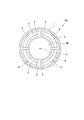
- the tilting pad bearing 100 of this embodiment is used to support the load of the rotating shaft 90 rotating about the axis A from the radial direction around the axis A.
- the tilting pad bearing 100 has an annular housing 1 centered on the axis A, and a plurality of (for example, four) pads 2 circumferentially spaced along the outer peripheral surface of the rotating shaft 90;
- a liner 3 supports the pads 2 from the outside in the radial direction, and a plurality of (for example, four) pivots 4 support the liners 3 on the inner peripheral surface of the housing 1.
- the rotating shaft 90 is used, for example, as a rotor of a rotating machine such as a steam turbine or a gas turbine.
- the rotation axis 90 has a cylindrical shape centered on the axis A. The rotation axis 90 rotates around the axis A.
- the pad 2 has a plate shape curved along the outer peripheral surface of the rotation shaft 90.
- the pad 2 is integrally formed of a metal material such as white metal.
- four pads 2 are arranged at intervals in the circumferential direction of the axis A.
- Lubricating oil is supplied between the inner peripheral surface of the pad 2 and the outer peripheral surface of the rotary shaft 90 by an oil supply device (not shown). The lubricating oil forms an oil film between the pad 2 and the rotating shaft 90.
- Each pad 2 is supported by the liner 3 from the radially outer side.
- the liner 3 when viewed in the direction of the axis A, the liner 3 is in the form of a curved plate having a radius of curvature substantially the same as that of the pad 2.
- the liner 3 is supported by a pivot 4 provided on the inner peripheral surface of the housing 1.
- a radially inner end of the pivot 4 is formed, for example, in a pointed shape, and supports the liner 3 at a point.
- the liner 3 can swing around the tip of the pivot 4.
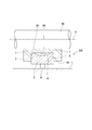
- FIG. 2 is a cross-sectional view of the rotation shaft 90 and the tilting pad bearing 100 in a plane including the axis A.
- the liner 3 is accommodated in an accommodation recess 5 formed in an outer side surface 2 ⁇ / b> A facing radially outward with respect to the axis A among the surfaces of the pad 2.
- the accommodation recess 5 is recessed in the shape of a square groove radially inward with respect to the axis A on the outer side surface 2A.
- the bottom surface 5A of the housing recess 5 is in the form of a plane extending substantially parallel to the axis A.
- the dimension of the liner 3 in the direction of the axis A is smaller than the dimension of the pad 2 in the direction of the axis A, and slightly smaller than the dimension of the accommodation recess 5 in the direction of the axis A.
- the pivot 4 supports the liner 3 from the radially outer side at a central position in the direction of the axis A of the liner 3.
- the inner surface 3A of the liner 3 (that is, the surface facing the pad 2) is formed with a recess 6 recessed in a direction away from the pad 2 (in other words, radially outward around the axis A).
- the recess 6 has an arc-shaped inner surface having a predetermined radius of curvature when viewed in a cross section including the axis A shown in FIG. 2, that is, in a direction orthogonal to the axis A.
- the recess 6 exemplified in this embodiment is formed in a shallow circular groove shape having the same radius of curvature at all positions in the direction orthogonal to the axis A (the front and back direction in FIG. 2).
- the end faces on both sides in the direction of the axis A of the recess 6 in the liner 3 formed in this way are contact portions 7 that contact the outer surface 2 A of the pad 2 (the bottom 5 A of the accommodation recess 5).
- the predetermined radius of curvature of the recess 6 in the liner 3 may be determined by simulation based on, for example, the material of the liner 3, the shape of the liner 3, the shape of the pad 2, the maximum value of the bearing load applied to the pad 2, etc. it can.
- the dimension of the recess 6 in the direction of the axis A is 1/2 or more, and may be 2/3 or more, with respect to the dimension of the liner 3 in the direction of the axis A.
- the recess 6 is formed at the center position of the liner 3 facing the pad 2. Therefore, a gap is formed between the liner 3 and the pad 2. That is, the liner 3 supports the bearing load applied to the pad 2 by the portion excluding the recess 6 (gap). In other words, both sides of the liner 3 adjacent to the recess 6 are pushed by the pad 2. When the bearing load is large, the pad 2 slightly bends in the direction in which the gap of the recess 6 narrows in the radial direction around the axis A.
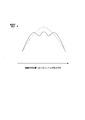
- FIG. 3 is a graph showing the distribution of the contact pressure in the direction of the axis A of the pad 2.
- the solid line indicates the pressure distribution when the recess 6 is formed in the liner 3 as in this embodiment
- the broken line indicates the pressure distribution when the recess 6 is not formed in the liner 3. .
- the pressure distribution of the pad 2 becomes chevron (in other words, reverse V-shaped) when the bearing load increases, and the center supported by the pivot 4 A peak of contact pressure appears at the position.
- the peak value of the pressure distribution is higher than when the recess 6 shown by the broken line is not formed even if the bearing load increases.
- the number of peaks increases from one to three. That is, the pressure distribution is averaged without the contact pressure being concentrated at a local position such as a central position. As a result, it is possible to suppress that the pad temperature rise and the local plastic flow occur.
- a second embodiment of the present invention will be described based on the drawings.
- the second embodiment is different from the first embodiment only in the configuration of the liner 3. Therefore, while attaching and explaining the same code to the same portion as a first embodiment, the overlapping explanation is omitted.
- a recess 6 is formed in the liner 3 of the tilting pad bearing 200 of the second embodiment.
- the small recess 8 is formed in the recess 6.
- the small recess 8 is formed in the recess 6 at a central position in the direction of the axis A.
- the small recess 8 has a smaller radius of curvature than the recess 6.
- the small recessed portion 8 is formed in a shallow circular groove shape having the same radius of curvature at all positions in the direction orthogonal to the axis line A (the front and back direction in FIG. 4). ing.
- the radius of curvature of the small recess 8 may be set in accordance with the peak value of the pressure distribution appearing at the central portion when only the recess 6 is formed.
- the radius of curvature of the small recess 8 can also be determined, for example, by simulation based on various conditions such as the shape and material of the pad 2 and the liner 3 as in the recess 6.
- the small recess 8 is further formed in the recess 6, when the bearing load is large, the pad 2 in the radial direction centering on the axis A, that is, the receiving recess
- the gap between the bottom surface 5A of 5 and the inner surface of the recess 6 can be bent in the narrowing direction.
- the small recessed part 8 is formed, even if the inner surface of the recessed part 6 contacts the pad 2, the condition where the inner surface of the small recessed part 8 does not contact the pad 2 can be created.
- the peak of the load at the central position where the pivot 4 is disposed can be reduced by the portion where the small concave portion 8 is formed and even when the bearing load is large. Thereby, the distribution of the contact pressure between the pad 2 and the rotation shaft 90 can be further suppressed from being concentrated only in the vicinity of the pivot 4.
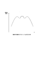
- FIG. 5 is a graph showing the distribution of the contact pressure in the direction of the axis A of the pad 2.
- the solid line shows the pressure distribution in the case where the recess 6 and the small recess 8 are formed in the liner 3 as in this embodiment, and the broken line shows that only the recess 6 is formed in the liner 3 and the small recess 8 is formed. It shows the pressure distribution when not being used.
- the peak value of the pressure distribution is smaller than in the case shown by the broken line, and the number of peaks is three to five. To increase. That is, the pressure distribution is averaged without the contact pressure being concentrated at a local position such as a central position. As a result, it is possible to further suppress the occurrence of the pad temperature rise and the local plastic flow.
- journal bearing in a third embodiment of the present invention will be described based on the drawings.
- the journal bearing of the third embodiment differs from the first embodiment described above only in that a recess is formed on the pad side. Therefore, while attaching and explaining the same code to the same portion as a first embodiment, the overlapping explanation is omitted.
- FIG. 6 is a cross-sectional view corresponding to FIG. 2 in the third embodiment of the present invention.
- the tilting pad bearing 300 in the third embodiment includes a housing 1, a pad 2, a liner 3 and a pivot 4.
- the liner 3 is housed in a housing recess 5 formed on the outer side surface 2A of the pad 2 facing radially outward with respect to the axis A.
- the accommodation recess 5 is recessed in the shape of a square groove radially inward with respect to the axis A on the outer side surface 2A.
- the inner surface 3A of the liner 3 (that is, the surface facing the pad 2) has a planar shape that extends substantially parallel to the axis A in a cross-sectional view in a plane including the axis A.
- the dimension of the liner 3 in the direction of the axis A is smaller than the dimension of the pad 2 in the direction of the axis A, and slightly smaller than the dimension of the accommodation recess 5 in the direction of the axis A.
- the pivot 4 supports the liner 3 from the radially outer side at a central position in the direction of the axis A of the liner 3.
- the bottom surface 5A of the housing recess 5 (that is, the surface facing the inner surface 3A of the liner 3) has a recess 306 recessed in a direction away from the liner 3 (in other words, radially inward around the axis A). It is formed. Similar to the recess 6 of the first embodiment described above, the recess 306 has an arc-shaped inner surface having a predetermined radius of curvature when viewed in a cross section including the axis A shown in FIG. 6, ie, a direction orthogonal to the axis A. have.
- the concave portion 306 exemplified in this embodiment is formed in a shallow circular groove shape having the same radius of curvature at all positions in the direction orthogonal to the axis A (the front and back direction in the drawing of FIG. 6).
- the end surface (bottom surface 5A of the accommodation recess 5) on both sides in the axial line A direction of the recess 306 in the pad 2 thus formed is an abutment portion 307 that abuts on the inner side surface 3A of the liner 3.
- the predetermined curvature radius of the concave portion 306 in the pad 2 is, for example, the material of the pad 2, the shape of the liner 3, the shape of the pad 2, the maximum value of the bearing load applied to the pad 2, etc. Based on this, it can be obtained by simulation or the like.
- the dimension of the recess 306 in the direction of the axis A is 1/2 or more, and may be 2/3 or more, with respect to the dimension of the liner 3 in the direction of the axis A.
- the recess 306 is formed at the central position of the pad 2 facing the liner 3. Therefore, a gap is formed between the liner 3 and the pad 2. That is, the liner 3 supports the bearing load applied to the pad 2 by the portion excluding the recess 306 (gap). In other words, both sides of the liner 3 adjacent to the recess 306 are pushed by the pad 2. When the bearing load is large, the pad 2 slightly bends in the direction in which the gap of the recess 306 narrows in the radial direction around the axis A.
- the present invention is not limited to the configurations of the above-described embodiments, and design changes can be made without departing from the scope of the invention.
- the configuration in which four pads 2 are provided has been described.
- the number of pads 2 is not limited to four, and may be four or less or five or more.
- Reference Signs List 1 housing 2 pad 2A outer surface 3 liner 3A inner surface 4 pivot 5 accommodation recess 5A bottom surface 6, 306 recess 306A inner surface 7 contact portion 8, 308 small recess 90 rotation shaft 100, 200, 300 tilting pad bearing A axis
Landscapes
- Engineering & Computer Science (AREA)
- General Engineering & Computer Science (AREA)
- Mechanical Engineering (AREA)
- Chemical & Material Sciences (AREA)
- Oil, Petroleum & Natural Gas (AREA)
- Physics & Mathematics (AREA)
- Fluid Mechanics (AREA)
- Sliding-Contact Bearings (AREA)
Priority Applications (4)
| Application Number | Priority Date | Filing Date | Title |
|---|---|---|---|
| CN201880065918.0A CN111201381B (zh) | 2017-10-31 | 2018-10-24 | 可倾瓦轴承 |
| KR1020207010613A KR102340555B1 (ko) | 2017-10-31 | 2018-10-24 | 틸팅 패드 베어링 |
| DE112018005071.8T DE112018005071T5 (de) | 2017-10-31 | 2018-10-24 | Kippsegmentlager |
| US16/754,252 US11261908B2 (en) | 2017-10-31 | 2018-10-24 | Tilting pad bearing |
Applications Claiming Priority (2)
| Application Number | Priority Date | Filing Date | Title |
|---|---|---|---|
| JP2017211141A JP6979332B2 (ja) | 2017-10-31 | 2017-10-31 | ティルティングパッド軸受 |
| JP2017-211141 | 2017-10-31 |
Publications (1)
| Publication Number | Publication Date |
|---|---|
| WO2019087890A1 true WO2019087890A1 (ja) | 2019-05-09 |
Family
ID=66331804
Family Applications (1)
| Application Number | Title | Priority Date | Filing Date |
|---|---|---|---|
| PCT/JP2018/039459 Ceased WO2019087890A1 (ja) | 2017-10-31 | 2018-10-24 | ティルティングパッド軸受 |
Country Status (6)
| Country | Link |
|---|---|
| US (1) | US11261908B2 (enExample) |
| JP (1) | JP6979332B2 (enExample) |
| KR (1) | KR102340555B1 (enExample) |
| CN (1) | CN111201381B (enExample) |
| DE (1) | DE112018005071T5 (enExample) |
| WO (1) | WO2019087890A1 (enExample) |
Families Citing this family (2)
| Publication number | Priority date | Publication date | Assignee | Title |
|---|---|---|---|---|
| DE102021124856A1 (de) | 2021-09-27 | 2023-03-30 | Voith Patent Gmbh | Kippsegmentradiallager und Wellenanordnung |
| JP7774487B2 (ja) | 2022-03-28 | 2025-11-21 | 三菱重工コンプレッサ株式会社 | ティルティングパッド軸受 |
Citations (5)
| Publication number | Priority date | Publication date | Assignee | Title |
|---|---|---|---|---|
| US2167882A (en) * | 1935-09-16 | 1939-08-01 | Gustave Fast Engineering Corp | Block bearing |
| JPS617616U (ja) * | 1984-06-20 | 1986-01-17 | 株式会社日立製作所 | テイルテイングパツド軸受 |
| JPH0979275A (ja) * | 1995-09-12 | 1997-03-25 | Mitsubishi Heavy Ind Ltd | 冷却装置付きジャーナル軸受 |
| JP2001124062A (ja) * | 1999-10-21 | 2001-05-08 | Hitachi Ltd | ティルティングパッド軸受装置 |
| JP2018159462A (ja) * | 2017-03-24 | 2018-10-11 | 三菱重工業株式会社 | ティルティングパッド軸受用の軸受パッド、ティルティングパッド軸受及び回転機械 |
Family Cites Families (14)
| Publication number | Priority date | Publication date | Assignee | Title |
|---|---|---|---|---|
| CH422435A (de) * | 1964-10-09 | 1966-10-15 | Escher Wyss Ag | Wellenlager mit auf kippbar gelagerten Lagersegmenten gleitendem Rotor |
| CH668811A5 (de) * | 1984-07-19 | 1989-01-31 | Glyco Metall Werke | Hydrodynamisches gleitlager. |
| CN87102236A (zh) * | 1987-05-19 | 1988-12-07 | 无锡机床厂 | 具有预加载荷的组装式多瓦调位轴承 |
| IE920985A1 (en) * | 1991-04-15 | 1992-10-21 | Russell D Ide | Hydrodynamic Bearings Having Spaced Bearing Pads and Methods¹of Making Same |
| JPH10288220A (ja) * | 1997-04-14 | 1998-10-27 | Ebara Corp | ティルティグパッド軸受 |
| JP2001271829A (ja) | 2000-03-28 | 2001-10-05 | Ntn Corp | 動圧型軸受ユニットおよびその製造方法 |
| DE10130253B4 (de) | 2001-06-22 | 2004-08-12 | Man B & W Diesel Ag | Gleitlager, insbesondere einer Pleuelstange für Hubkolbenbrennkraftmaschinen |
| JP4764486B2 (ja) | 2009-02-27 | 2011-09-07 | 三菱重工業株式会社 | ジャーナル軸受 |
| CN101761546A (zh) * | 2009-11-04 | 2010-06-30 | 西安交通大学 | 一种具有可倾瓦块和固定瓦块的组合型径向滑动轴承 |
| DE102010040244A1 (de) * | 2010-09-03 | 2012-03-08 | Man Diesel & Turbo Se | Kurbelwellenlagerung einer Kurbelwelle einer Brennkraftmaschine |
| JP6045813B2 (ja) | 2012-05-11 | 2016-12-14 | 株式会社東芝 | ティルティングパッドジャーナル軸受 |
| CN205298262U (zh) * | 2015-12-18 | 2016-06-08 | 中车集团台州第七八一六工厂 | 一种用于转子的可倾瓦轴承 |
| JP6793467B2 (ja) | 2016-05-25 | 2020-12-02 | 株式会社神戸製鋼所 | アルミニウム合金製部材及びlng気化器 |
| CN106015314B (zh) * | 2016-07-28 | 2019-04-12 | 西安交通大学 | 一种瓦块支点带弹簧的刚度可调式径向滑动轴承 |
-
2017
- 2017-10-31 JP JP2017211141A patent/JP6979332B2/ja active Active
-
2018
- 2018-10-24 KR KR1020207010613A patent/KR102340555B1/ko active Active
- 2018-10-24 WO PCT/JP2018/039459 patent/WO2019087890A1/ja not_active Ceased
- 2018-10-24 US US16/754,252 patent/US11261908B2/en active Active
- 2018-10-24 CN CN201880065918.0A patent/CN111201381B/zh active Active
- 2018-10-24 DE DE112018005071.8T patent/DE112018005071T5/de active Pending
Patent Citations (5)
| Publication number | Priority date | Publication date | Assignee | Title |
|---|---|---|---|---|
| US2167882A (en) * | 1935-09-16 | 1939-08-01 | Gustave Fast Engineering Corp | Block bearing |
| JPS617616U (ja) * | 1984-06-20 | 1986-01-17 | 株式会社日立製作所 | テイルテイングパツド軸受 |
| JPH0979275A (ja) * | 1995-09-12 | 1997-03-25 | Mitsubishi Heavy Ind Ltd | 冷却装置付きジャーナル軸受 |
| JP2001124062A (ja) * | 1999-10-21 | 2001-05-08 | Hitachi Ltd | ティルティングパッド軸受装置 |
| JP2018159462A (ja) * | 2017-03-24 | 2018-10-11 | 三菱重工業株式会社 | ティルティングパッド軸受用の軸受パッド、ティルティングパッド軸受及び回転機械 |
Also Published As
| Publication number | Publication date |
|---|---|
| DE112018005071T5 (de) | 2020-06-18 |
| KR20200047713A (ko) | 2020-05-07 |
| CN111201381B (zh) | 2022-03-11 |
| US11261908B2 (en) | 2022-03-01 |
| JP2019082233A (ja) | 2019-05-30 |
| JP6979332B2 (ja) | 2021-12-15 |
| US20200277985A1 (en) | 2020-09-03 |
| CN111201381A (zh) | 2020-05-26 |
| KR102340555B1 (ko) | 2021-12-20 |
Similar Documents
| Publication | Publication Date | Title |
|---|---|---|
| US10487871B2 (en) | Air foil journal bearing | |
| US20110150376A1 (en) | Trust foil bearing | |
| CN110462229B (zh) | 可倾瓦块轴承用的轴瓦、可倾瓦块轴承及旋转机械 | |
| US20150159692A1 (en) | Tilt pad bearing with through-pivot lubrication | |
| EP2850327B1 (en) | Journal oil bearing | |
| KR102166622B1 (ko) | 에어 포일 저널 베어링 | |
| WO2020130124A1 (ja) | スラストフォイル軸受 | |
| JP5922809B1 (ja) | ティルティングパッド軸受および回転機械 | |
| JP4554583B2 (ja) | スラスト軸受装置 | |
| WO2019087890A1 (ja) | ティルティングパッド軸受 | |
| US9618036B2 (en) | Tilting-pad bearing | |
| JP7482000B2 (ja) | ティルティングパッド式ジャーナル軸受およびそれを備える回転機械 | |
| JP2018013162A (ja) | フォイル軸受 | |
| EP2679842A1 (en) | Hydrodynamic journal bearing - especially for the use in steam turbine and other rotary equipment | |
| KR102371286B1 (ko) | 에어 포일 저널 베어링 | |
| JP6654081B2 (ja) | フォイル軸受 | |
| WO2024176423A1 (ja) | フォイル軸受及び回転機械 | |
| JP5807416B2 (ja) | ティルティングパッドジャーナル軸受 | |
| JP2015124775A (ja) | 軸受装置、回転機械 | |
| US20130071055A1 (en) | Fluid-riding device | |
| JP2006077871A (ja) | 軸受構造 | |
| JP2009287583A (ja) | フォイル軸受 | |
| JP2013194630A (ja) | ガスタービン | |
| JP2002188636A (ja) | すべり軸受 | |
| JP2008128318A (ja) | スラスト軸受構造 |
Legal Events
| Date | Code | Title | Description |
|---|---|---|---|
| 121 | Ep: the epo has been informed by wipo that ep was designated in this application |
Ref document number: 18874302 Country of ref document: EP Kind code of ref document: A1 |
|
| ENP | Entry into the national phase |
Ref document number: 20207010613 Country of ref document: KR Kind code of ref document: A |
|
| 122 | Ep: pct application non-entry in european phase |
Ref document number: 18874302 Country of ref document: EP Kind code of ref document: A1 |