WO2019082249A1 - 吸引成分生成装置、吸引成分生成装置を制御する方法、及びプログラム - Google Patents
吸引成分生成装置、吸引成分生成装置を制御する方法、及びプログラムInfo
- Publication number
- WO2019082249A1 WO2019082249A1 PCT/JP2017/038223 JP2017038223W WO2019082249A1 WO 2019082249 A1 WO2019082249 A1 WO 2019082249A1 JP 2017038223 W JP2017038223 W JP 2017038223W WO 2019082249 A1 WO2019082249 A1 WO 2019082249A1
- Authority
- WO
- WIPO (PCT)
- Prior art keywords
- threshold
- power supply
- control unit
- value
- notification
- Prior art date
Links
Images


Classifications
-
- A—HUMAN NECESSITIES
- A24—TOBACCO; CIGARS; CIGARETTES; SIMULATED SMOKING DEVICES; SMOKERS' REQUISITES
- A24F—SMOKERS' REQUISITES; MATCH BOXES; SIMULATED SMOKING DEVICES
- A24F40/00—Electrically operated smoking devices; Component parts thereof; Manufacture thereof; Maintenance or testing thereof; Charging means specially adapted therefor
- A24F40/50—Control or monitoring
- A24F40/53—Monitoring, e.g. fault detection
-
- A—HUMAN NECESSITIES
- A24—TOBACCO; CIGARS; CIGARETTES; SIMULATED SMOKING DEVICES; SMOKERS' REQUISITES
- A24F—SMOKERS' REQUISITES; MATCH BOXES; SIMULATED SMOKING DEVICES
- A24F40/00—Electrically operated smoking devices; Component parts thereof; Manufacture thereof; Maintenance or testing thereof; Charging means specially adapted therefor
- A24F40/60—Devices with integrated user interfaces
-
- A—HUMAN NECESSITIES
- A24—TOBACCO; CIGARS; CIGARETTES; SIMULATED SMOKING DEVICES; SMOKERS' REQUISITES
- A24F—SMOKERS' REQUISITES; MATCH BOXES; SIMULATED SMOKING DEVICES
- A24F40/00—Electrically operated smoking devices; Component parts thereof; Manufacture thereof; Maintenance or testing thereof; Charging means specially adapted therefor
- A24F40/80—Testing
-
- A—HUMAN NECESSITIES
- A24—TOBACCO; CIGARS; CIGARETTES; SIMULATED SMOKING DEVICES; SMOKERS' REQUISITES
- A24F—SMOKERS' REQUISITES; MATCH BOXES; SIMULATED SMOKING DEVICES
- A24F40/00—Electrically operated smoking devices; Component parts thereof; Manufacture thereof; Maintenance or testing thereof; Charging means specially adapted therefor
- A24F40/90—Arrangements or methods specially adapted for charging batteries thereof
-
- A—HUMAN NECESSITIES
- A61—MEDICAL OR VETERINARY SCIENCE; HYGIENE
- A61M—DEVICES FOR INTRODUCING MEDIA INTO, OR ONTO, THE BODY; DEVICES FOR TRANSDUCING BODY MEDIA OR FOR TAKING MEDIA FROM THE BODY; DEVICES FOR PRODUCING OR ENDING SLEEP OR STUPOR
- A61M15/00—Inhalators
- A61M15/06—Inhaling appliances shaped like cigars, cigarettes or pipes
-
- G—PHYSICS
- G01—MEASURING; TESTING
- G01R—MEASURING ELECTRIC VARIABLES; MEASURING MAGNETIC VARIABLES
- G01R19/00—Arrangements for measuring currents or voltages or for indicating presence or sign thereof
- G01R19/165—Indicating that current or voltage is either above or below a predetermined value or within or outside a predetermined range of values
- G01R19/16533—Indicating that current or voltage is either above or below a predetermined value or within or outside a predetermined range of values characterised by the application
- G01R19/16538—Indicating that current or voltage is either above or below a predetermined value or within or outside a predetermined range of values characterised by the application in AC or DC supplies
- G01R19/16542—Indicating that current or voltage is either above or below a predetermined value or within or outside a predetermined range of values characterised by the application in AC or DC supplies for batteries
-
- G—PHYSICS
- G01—MEASURING; TESTING
- G01R—MEASURING ELECTRIC VARIABLES; MEASURING MAGNETIC VARIABLES
- G01R31/00—Arrangements for testing electric properties; Arrangements for locating electric faults; Arrangements for electrical testing characterised by what is being tested not provided for elsewhere
- G01R31/36—Arrangements for testing, measuring or monitoring the electrical condition of accumulators or electric batteries, e.g. capacity or state of charge [SoC]
- G01R31/3644—Constructional arrangements
- G01R31/3646—Constructional arrangements for indicating electrical conditions or variables, e.g. visual or audible indicators
-
- G—PHYSICS
- G01—MEASURING; TESTING
- G01R—MEASURING ELECTRIC VARIABLES; MEASURING MAGNETIC VARIABLES
- G01R31/00—Arrangements for testing electric properties; Arrangements for locating electric faults; Arrangements for electrical testing characterised by what is being tested not provided for elsewhere
- G01R31/36—Arrangements for testing, measuring or monitoring the electrical condition of accumulators or electric batteries, e.g. capacity or state of charge [SoC]
- G01R31/392—Determining battery ageing or deterioration, e.g. state of health
-
- H—ELECTRICITY
- H01—ELECTRIC ELEMENTS
- H01M—PROCESSES OR MEANS, e.g. BATTERIES, FOR THE DIRECT CONVERSION OF CHEMICAL ENERGY INTO ELECTRICAL ENERGY
- H01M10/00—Secondary cells; Manufacture thereof
- H01M10/42—Methods or arrangements for servicing or maintenance of secondary cells or secondary half-cells
- H01M10/48—Accumulators combined with arrangements for measuring, testing or indicating the condition of cells, e.g. the level or density of the electrolyte
-
- H—ELECTRICITY
- H02—GENERATION; CONVERSION OR DISTRIBUTION OF ELECTRIC POWER
- H02J—CIRCUIT ARRANGEMENTS OR SYSTEMS FOR SUPPLYING OR DISTRIBUTING ELECTRIC POWER; SYSTEMS FOR STORING ELECTRIC ENERGY
- H02J7/00—Circuit arrangements for charging or depolarising batteries or for supplying loads from batteries
-
- A—HUMAN NECESSITIES
- A61—MEDICAL OR VETERINARY SCIENCE; HYGIENE
- A61M—DEVICES FOR INTRODUCING MEDIA INTO, OR ONTO, THE BODY; DEVICES FOR TRANSDUCING BODY MEDIA OR FOR TAKING MEDIA FROM THE BODY; DEVICES FOR PRODUCING OR ENDING SLEEP OR STUPOR
- A61M2205/00—General characteristics of the apparatus
- A61M2205/82—Internal energy supply devices
- A61M2205/8206—Internal energy supply devices battery-operated
-
- H—ELECTRICITY
- H02—GENERATION; CONVERSION OR DISTRIBUTION OF ELECTRIC POWER
- H02J—CIRCUIT ARRANGEMENTS OR SYSTEMS FOR SUPPLYING OR DISTRIBUTING ELECTRIC POWER; SYSTEMS FOR STORING ELECTRIC ENERGY
- H02J7/00—Circuit arrangements for charging or depolarising batteries or for supplying loads from batteries
- H02J7/0063—Circuit arrangements for charging or depolarising batteries or for supplying loads from batteries with circuits adapted for supplying loads from the battery
Definitions
- the present invention relates to a suction component generating device including a load that vaporizes or atomizes a suction component source by power from a power source.
- a suction component generation device (electronic cigarette) has been proposed which tastes suction components generated by vaporizing or atomizing a flavor source such as tobacco or an aerosol source with a load such as a heater instead of cigarettes (Patent Document 1- 8).
- the suction component generation device includes a load that vaporizes or atomizes the flavor source and / or the aerosol source, a power supply that supplies power to the load, and a control unit that controls the load and the power supply.
- Patent documents 2 to 7 disclose a suction component generating device provided with an LED (light emitting diode).
- Patent Documents 4 to 7 disclose changing the number of lighting or the lighting pattern of the light emitting elements (LEDs) provided in the device according to the charging rate of the power supply.
- Patent Document 9 discloses setting a management voltage value according to deterioration information of the power supply before the voltage of the power supply reaches the discharge termination voltage.
- the control unit executes processing for terminating the discharge of the secondary battery when the voltage of the power supply becomes equal to or lower than the management voltage value.
- the first feature acquires a load that vaporizes or atomizes a suction component source by power from a power source, a notification unit, and a value representing the remaining amount of the power source, and acquires an operation request signal to the load.
- Control unit for generating a command for operating the load the control unit, in the notification unit, a value representing the remaining amount of the power supply is less than a first threshold, and is more than the first threshold
- the second notification is configured to be performed when the second threshold is smaller than the second threshold, and the control unit performs the third notification when the value indicating the remaining amount of the power supply is less than the second threshold.
- the first threshold may be changed based on an algorithm, and the control unit may select one of the first threshold derived by the algorithm, among the plurality of first thresholds previously changed. To perform an annealing process close to at least one of Based on the derived value I, and summarized in that is configured to set the first threshold value.
- a second feature is the suction component production device according to the first feature, wherein the intensity of the smoothing process is changed based on the number of the first threshold values changed previously.
- a third feature is the suction component generation device according to the first feature or the second feature, wherein the number of the first threshold used for the smoothing process is the number of the first threshold previously changed.
- the gist is to be changed based on
- a fourth feature is the suction component generation device according to any one of the first feature to the third feature, wherein the control unit is capable of acquiring the degradation state of the power supply, and the strength of the smoothing process is The gist is to be changed based on the deterioration state.
- a fifth feature is the suction component generation device according to any of the fourth features, wherein the number of the first threshold used for the smoothing process is changed based on the deterioration state. .
- a sixth feature is the suction component production device according to the fourth feature or the fifth feature, wherein the strength of the annealing process is weakened as the deterioration state progresses.
- a seventh feature is the suction component generation device according to any one of the fourth to sixth features, wherein the control unit is configured to determine whether the deterioration state has progressed beyond a predetermined determination state.
- the gist of the present invention is to set the threshold to one-on-one threshold derived by the predetermined algorithm.
- An eighth feature is the suction component generation device according to any one of the fourth to seventh features, wherein the control unit is capable of acquiring the degradation state of the power supply, and the strength of the smoothing process is The method may be changed based on the number of the first threshold that has been changed and the degradation state weighted by the number of the first threshold.
- a ninth feature is the suction component production device according to the eighth feature, wherein the number of the first threshold used for the smoothing process is the number of the first threshold previously changed, and the first threshold.
- the gist is that the change is made based on the degradation state weighted by the number of threshold values.
- a tenth feature is the suction component generation device according to any one of the first feature to the ninth feature, wherein the control unit is configured to set the power supply when the set first threshold is greater than or equal to a predetermined determination value. And detecting the deterioration or abnormality of the
- An eleventh feature is the suction component generation device according to the tenth feature, wherein the control unit controls the notification unit to perform a fourth notification when the deterioration or abnormality of the power supply is detected. It is a summary.
- a twelfth feature is the suction component production device according to any one of the first feature to the eleventh feature, including a connecting portion capable of electrically connecting and disconnecting the load and the power source, wherein the control portion is In the smoothing process, it is a gist to use only the first threshold obtained after the load is attached to the connection.
- a thirteenth feature is a suction component generation device according to any one of the first to twelfth features, wherein a memory for storing a history of the first threshold, a load and the power supply are electrically disconnected.
- a possible connection unit, and the control unit is configured to disable or delete at least a part of the first threshold stored in the memory based on the removal of the load from the connection unit. I assume.
- a fourteenth feature is the suction component generation device according to any one of the first to thirteenth features, wherein the control unit determines that the value representing the remaining amount of the power supply is equal to or less than the second threshold. Alternatively, when the power supply is charged, the first threshold is changed.
- a fifteenth feature is a method of controlling a suction component generation device having a load for vaporizing or atomizing a suction component source by power from a power source, and obtaining a value indicating the remaining amount of the power source; Performing a second notification when the value representing the remaining amount of the power acquired in the acquiring step is less than a first threshold and equal to or greater than a second threshold smaller than the first threshold; and the power acquired in the acquiring step Performing a third notification when the value representing the remaining amount of the second threshold is less than the second threshold, and a plurality of the first thresholds that are previously changed with respect to the one-on-one threshold derived using the algorithm And setting the first threshold value based on the value subjected to the annealing process approaching at least one of them.
- a sixteenth feature is summarized as a program that causes the suction component generation device to perform the method according to the fifteenth feature.
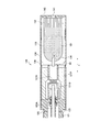
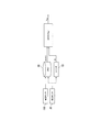
- FIG. 1 is a schematic view of a suction component generation device according to one embodiment.
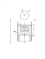
- FIG. 2 is a schematic view of an atomization unit according to an embodiment.
- FIG. 3 is a schematic view showing an example of the configuration of a suction sensor according to an embodiment.
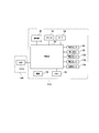
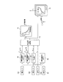
- FIG. 4 is a block diagram of a suction component generation device.
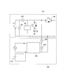
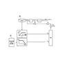
- FIG. 5 is a diagram showing an electric circuit of the atomization unit and the electrical component unit in a state where a load is connected.
- FIG. 6 is a diagram showing an electric circuit of the charger and the electrical unit in a state where the charger is connected.
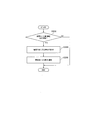
- FIG. 7 is a flowchart showing an example of a control method of the suction component generation device.
- FIG. 1 is a schematic view of a suction component generation device according to one embodiment.
- FIG. 2 is a schematic view of an atomization unit according to an embodiment.
- FIG. 3 is a schematic view showing an example of the configuration of a suction sensor according to an embodiment.
- FIG. 8 is a graph showing the relationship between the number of puff operations by the user and the value indicating the remaining amount of power.
- FIG. 9 is a view showing an example of a light emission pattern of the light emitting element in the normal use mode and the charge request mode.
- FIG. 10 is a diagram showing an example of the light emission pattern of the light emitting element in the abnormality notification mode.
- FIG. 11 is a flowchart illustrating an example of the threshold value changing process.
- FIG. 12 shows an example of a block diagram of a control unit for implementing a predetermined algorithm.
- FIG. 13 shows another example of a block diagram of a control unit for implementing a predetermined algorithm.
- FIG. 14 is a flowchart illustrating another example of the threshold value changing process.
- FIG. 15 is a graph showing how the voltage value of the power supply is charged when charging is started before the voltage of the power supply reaches the discharge termination voltage.
- FIG. 16 shows another example of a block diagram of a control unit for implementing a predetermined algorithm.
- FIG. 17 shows an example of a block diagram of a control unit for performing the smoothing process.
- FIG. 18 illustrates an example of a block diagram of a control unit for performing the correction of the first threshold in the case of performing the threshold value changing process after leaving for a long time.
- FIG. 19 is a flowchart illustrating an example of the abnormality determination process.
- Patent Document 9 discloses setting a management voltage value according to deterioration information of a secondary battery before the voltage of the power supply reaches the discharge termination voltage.
- the control voltage value is used as an index for terminating the discharge of the secondary battery.
- this control voltage value is set based on the deterioration information of the secondary battery, it is difficult to accurately calculate the deterioration information of the secondary battery. Therefore, the calculated value of the deterioration information of the secondary battery may greatly vary every time it is calculated. As described above, it is not preferable to control the apparatus based on the value that may greatly vary with each calculation.
- the suction component generation device acquires a load that vaporizes or atomizes the suction component source by the power from the power source, a notification unit, and a value representing the remaining amount of the power source, and And a controller configured to acquire an operation request signal and generate a command for operating the load.
- the control unit is configured to cause the notification unit to perform the second notification when the value indicating the remaining amount of the power supply is less than a first threshold and greater than or equal to a second threshold that is smaller than the first threshold. Further, the control unit is configured to cause the notification unit to perform a third notification when the value indicating the remaining amount of the power supply is less than the second threshold.
- the first threshold can be changed based on an algorithm.
- the control unit is based on a value derived by performing an averaging process that brings the one-time-one threshold value derived by the algorithm closer to at least one of the plurality of first threshold values changed previously.
- the first threshold is configured to be set.
- the first threshold described above is set based on the value derived by performing the averaging process closer to at least one of the plurality of previously changed first thresholds. Therefore, even if the accuracy of the one threshold derived by the above algorithm is not good, the variation in the first threshold is reduced by the smoothing process. Therefore, it is possible to suppress the user from performing the second notification at an undesirable timing due to the derived one-to-one variation in the threshold value, and it is possible to prevent a sense of discomfort given to the user.
- FIG. 1 is an exploded view showing a suction component generation device according to one embodiment.
- FIG. 2 is a view showing an atomization unit according to an embodiment.
- FIG. 3 is a schematic view showing an example of the configuration of a suction sensor according to an embodiment.
- FIG. 4 is a block diagram of a suction component generation device.
- FIG. 5 is a diagram showing an electric circuit of the atomization unit and the electrical component unit in a state where a load is connected.
- FIG. 6 is a diagram showing an electric circuit of the charger and the electrical unit in a state where the charger is connected.
- the suction component generation device 100 may be a non-burning type flavor suction device for suctioning a suction component (flavoring component) without combustion.
- the suction component generation device 100 may have a shape extending along a predetermined direction A which is a direction from the non-sucking end E2 to the suction end E1.
- the suction component generation device 100 may include one end E1 having a suction port 141 for suctioning a suction component, and the other end E2 opposite to the suction port.
- the suction component generation device 100 may have an electrical unit 110 and an atomization unit 120.
- the atomization unit 120 may be configured to be detachable from the electrical unit 110 via mechanical connection parts 111 and 121.
- a load 121R which will be described later, in the atomization unit 120 is provided with the electrical unit 110 via the electrical connection terminals 110t and 120t.
- the power supply 10 is electrically connected. That is, the electrical connection terminals 110 t and 120 t constitute a connection portion capable of electrically connecting and disconnecting the load 121 R and the power supply 10.
- the atomization unit 120 has a suction component source sucked by the user, and a load 121 R that vaporizes or atomizes the suction component source by the power from the power source 10.
- the aspiration component source may include an aerosol source that generates an aerosol, and / or a flavor source that generates a flavor component.
- the load 121R may be any device capable of generating an aerosol and / or a flavor component from an aerosol source and / or a flavor source by receiving power.
- the load 121R may be a heating element such as a heater or an element such as an ultrasonic wave generator.
- the heat generating element include a heat generating resistor, a ceramic heater, and a heater of an induction heating type.
- the atomization unit 120 may include a reservoir 121P, a wick 121Q, and a load 121R.
- the reservoir 121P may be configured to store a liquid aerosol source or a flavor source.
- the reservoir 121P may be, for example, a porous body made of a material such as a resin web.
- the wick 121Q may be a liquid holding member that draws in an aerosol source or a flavor source from the reservoir 121P using capillary action.
- the wick 121Q can be made of, for example, glass fiber or porous ceramic.
- the load 121R atomizes the aerosol source held by the wick 121Q or heats the flavor source.
- the load 121R is formed of, for example, a resistive heating element (for example, a heating wire) wound around the wick 121Q.
- the air flowing in from the inflow hole 122A passes near the load 121R in the atomization unit 120.
- the suction component generated by the load 121R flows with the air towards the suction port.
- the aerosol source may be liquid at ambient temperature.
- polyhydric alcohols can be used as an aerosol source.
- the aerosol source itself may have a flavor component.
- the aerosol source may include a tobacco material which releases flavoring ingredients by heating, or an extract derived from the tobacco material.
- the atomization unit 120 may include a replaceable flavor unit 130.
- the flavor unit 130 has a cylinder 131 containing a flavor source.
- the cylinder 131 may include the film member 133 and the filter 132.
- a flavor source may be provided in the space formed by the membrane member 133 and the filter 132.
- the atomization unit 120 may include the destruction unit 90.
- the destruction part 90 is a member for destroying a part of the membrane member 133 of the flavor unit 130.
- the destruction portion 90 may be held by a partition member 126 for separating the atomization unit 120 and the flavor unit 130.
- the partition member 126 is, for example, polyacetal resin.
- the breaking part 90 is, for example, a cylindrical hollow needle. By piercing the tip of the hollow needle into the membrane member 133, an air flow path is formed that allows the atomization unit 120 and the flavoring unit 130 to be in air communication.
- a mesh having a roughness that does not allow passage of the flavor source is provided inside the hollow needle.
- the flavor source in the flavor unit 130 imparts a flavor ingredient to the aerosol generated by the load 121 R of the atomization unit 120.
- the flavor imparted to the aerosol by the flavor source is carried to the mouth of the aspiration component generator 100.
- the suction component generation device 100 may have a plurality of suction component sources.
- the aspiration component generator 100 may have only one aspiration component source.
- the flavor source in the flavor unit 130 may be solid at normal temperature.
- the flavor source is constituted by a raw material piece of plant material that imparts a flavor and taste component to the aerosol.
- a raw material piece which comprises a flavor source the molded object which shape
- the flavor source may be a molded article obtained by forming the tobacco material into a sheet.
- the raw material piece which comprises a flavor source may be comprised by plants (for example, mint, herbs, etc.) other than tobacco.
- the flavor source may be provided with a flavor such as menthol.
- the suction component generation device 100 may include a mouthpiece 142 having a suction port 141 for the user to suction the suction component.
- the mouthpiece 142 may be configured to be removable from the atomization unit 120 or the flavor unit 130, and may be configured to be integral and inseparable.
- the electrical unit 110 may include the power supply 10, the suction sensor 20, the push button 30, the notification unit 40, and the control unit 50.
- the power supply 10 stores the power necessary for the operation of the flavor suction device 100.
- the power source 10 may be removable from the electrical unit 110.
- the power source 10 may be a rechargeable battery, such as, for example, a lithium ion secondary battery.
- the load 121R provided in the atomization unit 120 is electrically connected to the power supply 10 of the electrical unit 110 (see FIG. 5).
- the suction component generation device 100 may include a switch 140 capable of electrically connecting and disconnecting the load 121R and the power supply 10.
- the switch 140 is opened and closed by the control unit 50.
- the switch 140 may be configured of, for example, a MOSFET.
- switch 140 When the switch 140 is turned on, power is supplied from the power supply 10 to the load 121R. On the other hand, when the switch 140 is turned off, the supply of power from the power supply 10 to the load 121R is stopped. The on / off of the switch 140 is controlled by the control unit 50.
- the control unit 50 may include an operation request sensor that detects an operation related to the user's operation request.
- the operation request sensor may be, for example, a push button 30 pressed by the user or a suction sensor 20 that detects a suction operation of the user.
- the control unit 50 acquires an operation request signal to the load 121R and generates a command for operating the load 121R.
- the control unit 50 outputs a command for operating the load 121R to the switch 140, and the switch 140 is turned on according to the command.
- the control unit 50 is configured to control power feeding from the power supply 10 to the load 121R. When power is supplied from the power supply 10 to the load 121R, the load 121R vaporizes or atomizes the suction component source.
- the suction component generation device 100 may include at least one of a voltage sensor 150, a current sensor 152, and a temperature sensor 154, as necessary.
- the temperature sensor 154 is not shown in FIGS. 5 and 6.
- Voltage sensor 150 may be configured to be capable of detecting the voltage of power supply 10.
- the current sensor 152 may be configured to be able to detect the amount of current flowing out of the power supply 10 and the amount of current flowing into the power supply 10.
- the temperature sensor 154 may be configured to be able to detect, for example, the temperature near the power supply 10.
- the control unit 50 is configured to be able to obtain the outputs of the voltage sensor 150, the current sensor 152, and the temperature sensor 154. The control unit 50 performs various controls using these outputs.
- the suction sensor 20 is a sensor that outputs a value (for example, a voltage value or a current value) that changes in accordance with the flow rate of air sucked from the non-sucking side toward the sucking side (that is, puff operation of the user). Good.
- a value for example, a voltage value or a current value
- Such sensors include, for example, condenser microphone sensors and known flow sensors.
- FIG. 3 shows a specific example of the suction sensor 20.
- the suction sensor 20 illustrated in FIG. 3 includes a sensor body 21, a cover 22, and a substrate 23.
- the sensor body 21 is configured of, for example, a capacitor.
- the electric capacity of the sensor body 21 changes due to the vibration (pressure) generated by the air drawn from the air introduction hole 125 (that is, the air drawn from the non-suction side toward the suction side).
- the cover 22 is provided on the suction side with respect to the sensor body 21 and has an opening 22A. By providing the cover 22 having the opening 22A, the electric capacity of the sensor body 21 is easily changed, and the response characteristic of the sensor body 21 is improved.
- the substrate 23 outputs a value (here, a voltage value) indicating the electric capacitance of the sensor body 21 (capacitor).
- the suction component generation device 100 may be configured to be connectable to a charger 200 for charging the power supply 10 in the electrical unit 110 (see FIG. 6).
- the charger 200 is electrically connected to the power supply 10 of the electrical unit 110.
- the electrical unit 110 may have a determination unit that determines whether the charger 200 is connected.
- the determination unit may be, for example, a unit that determines the presence or absence of connection of the charger 200 based on a change in potential difference between a pair of electric terminals to which the charger 200 is connected.
- the determination unit is not limited to this means, and may be any means as long as it can determine the presence or absence of the connection of the charger 200.
- the charger 200 has an external power supply 210 for charging the power supply 10 in the electrical unit 110.
- the aspiration component generator 100 may be in communication with the processor 250 of the charger 200.
- the processor 250 may be configured to be capable of controlling at least one of the discharge from the power supply 10 to the external power supply 210 and the charging from the external power supply 210 to the power supply 10.
- the charger 200 may have a current sensor 230 for acquiring the value of the charging current, and a voltage sensor 240 for acquiring the value of the charging voltage.
- the control unit 50 may have a counter 52 that counts the number of times the puff operation of the user is detected.
- the control unit 50 may have a timer 54 that measures the time elapsed from the detection of the puff operation of the user, that is, the acquisition of the operation request signal to the load 121R.
- the notification unit 40 issues a notification for notifying the user of various types of information.
- the notification unit 40 may be, for example, a light emitting element such as an LED. Instead of this, the notification unit 40 may be an element that generates a sound or a vibrator.
- the control unit 50 may be configured to be able to control the notification unit 40 to operate in any of the normal use mode, the charge request mode, and the abnormality notification mode. The normal use mode, the charge request mode, and the abnormality notification mode will be described later.
- the light emitting element is preferably provided on the side surface 124 extending between the suction end E1 and the non-sucking end E2 (see FIG. 1).
- the length from the suction end E1 to the light emitting element is preferably 58 mm or more, more preferably 100 mm or more.
- the length from one end E1 to the other end E2 is preferably 135 mm or less.
- the light emitting element may be provided across the non-sucking end E2 of the suction component generating device 100 and a part of the side surface 124 extending between the sucking end E1 and the non-sucking end E2.
- the length from one end E1 to the other end E2 that is, the approximate length from the suction end E1 to the light emitting element is preferably 58 mm or more, more preferably 100 mm or more.
- the length from one end E1 to the other end E2 is preferably 135 mm or less. This length may be set from the viewpoint of imitating the shape of a widely distributed cigarette, or from the viewpoint that the notification unit 40 falls within the field of view of the user when the user holds the end E1 in the mouth .
- the distance from the user's eye to the other end E2 of the suction component generation device 100, that is, the light emitting element can be secured.
- the distance between both eyes of a general user is 100 mm and considering the consideration of peripheral vision, when the light emitting element emits light in purple, the length from the suction end E1 to the light emitting element is 58 mm or more
- the user can start to recognize the color of the light emitting element even in the state where the front is facing the front center. That is, even if the user does not look at the light emitting element, it is possible to easily recognize the difference in color of the light emitting element.
- the recognition rate for purple of the user exceeds 50%.
- color recognition refers to the ability to distinguish one color from another. Further, it is not necessary to be able to distinguish between a plurality of colors belonging to similar colors, and at least a plurality of colors that do not belong to similar colors and are easy to distinguish may be distinguished.
- the length by which the user starts to recognize the color of the light emitting element and the length at which the recognition rate for the color of the user exceeds 50% are values in an example in which the light emitting element emits purple light. .
- the length from the inlet end E1 to the light emitting element may be determined based on the color that the user particularly wants to recognize among the emission colors of the light emitting element.
- the light emitting element is provided on a part of the side surface 124 extending between the suction end E1 and the non-sucking end E2, it is easy for the user to recognize the color of the light emitting element while wearing the suction component generating device. There is a merit.
- FIG. 7 is a flowchart showing an example of a control method of the suction component generation device.
- FIG. 8 shows the relationship between the number of puff operations by the user and a value indicating the remaining amount of power.
- the counter 52 preferably measures the number of times the user has performed a puff operation.
- Control unit 50 monitors whether or not charging of power supply 10 has been performed by charger 200 (step S100). The determination as to whether charging has been performed can be made by monitoring a value indicating the remaining amount of the power supply 10. For example, when the value indicating the remaining amount of the power supply 10 has increased to a predetermined amount or more, the control unit 50 can determine that charging has been performed. Alternatively, when the current sensor 152 provided in the electrical unit 110 detects a charging current for charging the power supply 10, it may be determined that charging has been performed. Alternatively, if it is communicated that charging is being performed from the charger 200 to the electrical unit 110 by means of communication means (not shown) enabling communication between the electrical unit 110 and the charger 200 instead. It may be determined that charging has been performed.
- PLC power line carrier communication
- the value indicating the remaining amount of the power source 10 may be, for example, the voltage of the power source 10, the charging rate (SOC) of the power source 10, or the remaining capacity of the power source.
- the voltage of the power supply 10 may be an open circuit voltage (OCV) obtained without electrically connecting the load 121R to the power supply 10, or a closed circuit voltage obtained by electrically connecting the load to the power supply (CCV) may be sufficient.
- OCV open circuit voltage
- CCV closed circuit voltage obtained by electrically connecting the load to the power supply
- the remaining amount of the power supply 10 is indicated in order to eliminate the influence of changes in internal resistance and temperature accompanying voltage drop or discharge accompanying electrical connection of the load 121R.
- the value is preferably defined by the open circuit voltage (OCV) rather than the closed circuit voltage (CCV).
- control unit 50 When charging is performed, the control unit 50 preferably sets the value of the counter 52 to "0" (step S102). As a result, the counter 52 can measure the number of puff operations since the charging.
- control unit 50 may perform the threshold value changing process S104 as necessary when the charging is performed.
- the threshold value changing process S104 will be described in detail below.
- control unit 50 stands by until an operation request signal to the load 121R is acquired (step S106).
- the operation request signal to the load 121R is input to the control unit 50 from the above-described operation request sensor according to the operation of the user.
- the control unit 50 acquires a value indicating the remaining amount of the power supply 10 (step S108).
- the example of the value which shows the residual amount of the power supply 10 is as having mentioned above.
- the acquired value indicating the remaining amount of the power supply 10 is stored in the memory 58.
- the abnormality notification mode is a mode indicating that the remaining amount of the power supply 10 is 0 or extremely low, and the load 121R can not normally generate the aspiration component from the aspiration component source.
- the second threshold may be defined by, for example, a value corresponding to 0 or a remaining amount of power in the vicinity of 0.
- the second threshold may be defined by, for example, a discharge termination voltage or a voltage slightly larger than the discharge termination voltage.
- the second threshold is defined, for example, by the charging end rate or the remaining capacity corresponding to the discharge end voltage or a voltage slightly larger than the discharge end voltage. It may be done.
- the control unit 50 may stand by in the abnormality notification mode without supplying power to the load 121R. Alternatively, the control unit 50 may automatically turn off the suction component generation device 100 when entering the abnormality notification mode.
- the control unit 50 executes threshold value change processing (step S114) as necessary. Details of the threshold value changing process S114 will be described later.
- the control unit 50 controls the notification unit 40 in the normal use mode to cause the notification unit 40 to perform the first notification.
- the normal use mode is a mode in which the remaining amount of the power supply 10 is sufficiently large and the load 121R can generate a suction component from the suction component source.
- the first threshold is used to distinguish between the normal use mode and the charge request mode described later.
- control unit 50 obtains an operation request signal to load 121R and generates a command for operating load 121R.
- the switch 140 is turned on based on this command, whereby power is supplied to the load 121R (step S120).
- the load 121R generates a suction component from the suction component source.
- the generated suction component is inhaled by the user via the suction port.
- the control unit 50 may control the amount of power supplied to the load 121R by pulse width control (PWM).
- PWM pulse width control
- control unit 50 determines that the operation request operation (suction operation) of the user is completed based on the operation request signal from the operation request sensor, the control unit 50 turns off the switch 140 to stop the power supply to the load 121R (step S122, step S124).
- control unit 50 may forcibly stop the power supply to the load 121R when the operation request operation (suction operation) of the user continues beyond the predetermined period.
- the above predetermined period for forcibly stopping the power supply to the load 121R may be set based on the period of one suction operation of a normal user, for example, set in the range of 2 to 4 seconds It may be done.
- control unit 50 When the control unit 50 detects a puff operation of the user based on the operation request signal from the operation request sensor, the control unit 50 increases the value of the counter 52 that measures the number of puff operations by one. Further, the control unit 50 resets the timer 54, and measures the elapsed time by the timer 54 (step S128). As a result, the control unit 50 can use the timer 54 to measure the leaving time, which is a period during which power is not supplied to the load 121R.
- Step S100 When the power supply to the load 121R is stopped, the control unit 50 returns to the standby state, and the control unit 50 again monitors whether charging has been performed (step S100) and whether an operation request signal to the load 121R has been acquired. (Step S106).
- the control unit 50 controls the notification unit 40 in the charge request mode and performs the second notification to the notification unit 40. (Steps S110, S116 and S119).
- the charge request mode is provided for notifying the user of a decrease in the remaining amount of the power supply 10 and requesting the user to charge although the suction component can be generated by the power supply to the load 121R.
- the control unit 50 acquires an operation request signal to the load 121R and generates a command for operating the load 121R, as in the normal use mode.
- the switch 140 is turned on based on this command, whereby power is supplied to the load 121R (step S120).
- the load 121R generates a suction component from the suction component source.
- the steps (steps S120, S122, and S124) from the start to the end of the power supply to the load 121R in the charge request mode can be performed as in the normal use mode, as described above.
- the control unit 50 detects a puff operation of the user, the control unit 50 also increases the value of the counter 52 by one even in the charge request mode (step S126).
- control unit 50 resets the timer 54, and measures the elapsed time by the timer 54 (step S128). As a result, the control unit 50 can use the timer 54 to measure the leaving time, which is a period during which power is not supplied to the load 121R.
- the first threshold described above is a variable value that can be changed based on the operation request signal to the load 121R acquired by the control unit 50. That is, the conditions for switching between the normal use mode and the charge request mode are changed based on the operation request signal.
- the change of the first threshold is automatically performed by the control unit 50, for example, in the above-described threshold change process.
- the first threshold is changed based on a value relating to the power supply from the power supply 10 to the load 121R.
- the value regarding the power supply may be the voltage of the power supply 10, the charging rate of the power supply 10, or the remaining capacity of the power supply. More specifically, the first threshold is changed based on, for example, the voltage drop of the power supply 10 for each puff, the decrease of the charging rate of the power supply 10 for each puff, or the decrease of the remaining capacity of the power supply 10 for each puff. Just do it.
- the operation request signal outputs a signal according to the usage by the user.
- the suction sensor 20 outputs an output signal (operation request signal) according to the suction amount per suction and the suction time per puff of the user (see the upper graphs in FIGS. 9 and 10).
- the first threshold when the first threshold can be changed based on an operation request signal to the load 121R, for example, a value related to power supply to the load 121R, the first threshold can be changed according to how the load 121R is used.
- the timing at which the second notification is notified can be changed according to how the suction component generation device is used by the user. Therefore, according to this aspect, it is possible to notify the second notification at a more appropriate timing according to how the suction component generation device is used by the user.
- the first notification, the second notification, and the third notification described above are different from each other. That is, in the embodiment described above, the notifications of the notification unit 40 in the normal use mode, the charge request mode, and the abnormality notification mode are different from each other. Therefore, the notification unit 40 can cause the user to recognize the distinction between the remaining amount and / or the mode of the power supply 10 by at least three different types of notification according to the remaining amount of the power supply 10.
- the notification unit 40 can notify the user of the difference between the normal use mode, the charge request mode, and the abnormality notification mode by different notifications.
- An aspiration component generation device such as an electronic cigarette includes a reservoir 121P and a flavor unit 130 for storing or containing an aerosol source or / and a flavor source, and a difficult-to-miniaturize component such as the power source 10 as an essential component. It must mimic the shape and weight of widely distributed cigarettes. Therefore, restrictions on user interface (U / I) and layout (L / O) are particularly severe.
- the notification unit 40 effectively uses the difference between the notification different from each other, for example, the notification mode, to effectively use the difference between the normal use mode, the charge request mode, and the abnormality notification mode. It can be made to recognize.
- the notification unit 40 preferably includes a light emitting element.
- the first notification, the second notification, and the third notification may be respectively configured by a first light emission color, a second light emission color, and a third light emission color by the light emitting element.
- the first light emission color, the second light emission color, and the third light emission color are different from each other.
- the first light emission color includes a cold color
- the second light emission color includes a middle color
- the third light emission color includes a warm color.
- the “middle color” as the second light emission color is defined by the color located between the first light emission color that is “cold” and the third light emission color that is “warm” in the hue circle.
- the “hue ring” is defined, for example, by a hue ring in which the hues in the Munsell color system are ordered and annularly arranged.
- the “warm color” may be defined by light having a light spectrum peak in a region having a hue of 10 RP to 10 Y in the Munsell color system, or in a wavelength range of 570 nm to 830 nm.
- the "warm color” can exemplify, for example, red.
- “Cold color” may be defined by light having a light spectrum peak in a region having a hue of 5BG to 5PB in the Munsell color system, or in a wavelength band of 450 nm to 500 nm.
- Cold color can illustrate, for example, blue.
- the “intermediate color” may be defined by light having a light spectral peak in a region having a hue of 5 PB to 10 RP in the Munsell color system, or in a wavelength band of 380 to 450 nm.
- the “middle color” may be, for example, purple.
- the third light emission color in the abnormality notification mode includes a warm color, it is possible to effectively impress the user that an abnormality has occurred, specifically, that the remaining amount of the power supply 10 has been exhausted.
- the first luminescent color in the normal use mode includes a cold color, it is possible to impress the user that the suction component generating device 100 is operating without any problem.
- the second emission color in the charge request mode is an intermediate color between the first emission color and the third emission color, the remaining amount of the power supply 10 is depleted from the normal use mode in which the remaining amount of the power supply 10 is sufficient. It is possible to effectively impress the user that the transition to the abnormal notification mode is being made.
- the distance on the hue circle between the complementary color of the first light emission color and the third light emission color is shorter than the distance on the hue circle between the complementary color of the first light emission color and the second light emission color.
- the distance on the hue circle between the complementary color of the third luminescent color and the first luminescent color is on the hue circle between the complementary color of the third luminescent color and the second luminescent color It is preferable to be shorter than the distance.
- the “complementary color” of a certain color means a color located on the hue circle in the opposite (ie, diagonally opposite) to the color.
- the combination of a certain color and its complementary color corresponds to a combination of colors that make each other stand out. Therefore, when the third light emission color is closer to the complementary color of the first light emission color on the hue circle than the second light emission color, the user can more easily distinguish the third light emission color from the first light emission color. Thereby, it is possible to effectively impress the user that the mode associated with the third light emission color is a mode opposite to the normal use mode related to the first light emission color, that is, the abnormality notification mode.
- the wavelength of the light corresponding to the second emission color may be closer to the wavelength of the light corresponding to the first emission color than the wavelength of the light corresponding to the third emission color.
- the light emitting element has a light spectrum peak that protrudes in a specific wavelength band, such as an LED, it is preferable that the wavelength of light in each emission color satisfy such a relationship.
- the first notification may be configured by blue light by the light emitting element
- the second notification may be configured by violet light by the light emitting element
- the third notification may be configured by red light by the light emitting element.
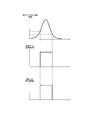
- FIG. 9 is a view showing an example of a light emission pattern of the light emitting element in the normal use mode and the charge request mode.
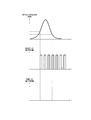
- FIG. 10 is a diagram showing an example of the light emission pattern of the light emitting element in the abnormality notification mode.
- the upper graph shows the time dependency of the output value of the operation request sensor, for example, the suction sensor 20.
- the middle graphs show the time dependency of the power supply to the light emitting element.
- the lower graph shows the time dependency of the power supply to the load 121R.
- the light emitting element may continuously emit light in each of the normal use mode, the charge request mode, and the abnormality notification mode, or may blink by repeating light emission and non-light emission.
- the light emitting element emits light for a desired period in the normal use mode and the charge request mode.
- the light emitting element repeats light emission and non-light emission in the abnormality notification mode.
- the control unit 50 may start emitting light from the light emitting element using the operation request signal as a trigger.
- the operation request sensor is the suction sensor 20 that outputs a value related to the flow velocity in the suction component generation device 100, as shown in FIGS. 9 and 10, the output value of the suction sensor 20 has a predetermined threshold value.
- the control unit 50 may start supplying power to the light emitting element and may cause the light emitting element to emit light.
- the control unit 50 determines that the operation request operation (suction operation) of the user is completed, the light emission of the light emitting element may be ended.
- the operation request sensor is the suction sensor 20 that outputs a value related to the flow velocity in the suction component generation device 100, as shown in FIG. 9, the output value of the suction sensor 20 falls below another predetermined threshold.
- the control unit 50 may stop the supply of the power to the light emitting element to make the light emitting element emit no light. That is, the control unit 50 variably controls the periods of the first notification and the second notification performed by the notification unit 40 according to the period in which the operation request signal from the suction sensor 20 is continuously acquired.
- the operation request signal may be output from a sensor other than the suction sensor 20.
- the control unit 50 controls the period of the first notification and the second notification performed by the notification unit 40 according to the period in which the operation request signal from the push button 30 is continuously acquired. May be variably controlled.
- the light emission patterns of the light emitting elements in the first notification in the normal use mode and the second notification in the charge request mode are the same (see FIG. 9). Specifically, at least one, and more preferably both of the notification timing and notification period of the first notification and the second notification when the control unit 50 detects the operation request signal may be the same as each other.
- the timing at which the notification unit 40 starts and ends the first notification and the second notification may be the same as the timing at which the supply of power to the load 121R is started and the timing at which the supply is ended. .
- the timing for ending the second notification in the charge request mode may be longer than the timing for ending the supply of power to the load 121R, more preferably the timing for ending the puff operation.
- the control unit 50 may be configured to control the notification unit 40 so as to perform the third notification only during a predetermined period that does not depend on the period in which the operation request signal is continuously acquired (see FIG. 10). That is, the notification unit 40 may perform the third notification only for a predetermined period without being influenced by the time of the puff operation of the user. In this case, it is preferable that the period in which the notification unit 40 performs the first notification and the second notification is shorter than the above-described predetermined period in which the third notification is performed.
- the predetermined period in which the third notification is performed may be set to be longer than the period of one suction operation of a normal user, and may be set in the range of 4.5 to 6 seconds, for example.
- the third notification in the abnormality notification mode can be easily distinguished from the first notification in the normal use mode and the second notification in the charge request mode.
- the third notification continues for a longer period than the first notification in the normal use mode and the second notification in the charge request mode, the user can be effectively notified that charging is required.
- the first notification in the normal use mode is configured by blue light by the light emitting element
- the second notification in the charge request mode is configured by violet light by the light emitting element
- the third notification in the abnormality notifying mode is the light emitting element Described an embodiment configured by red light.
- the light emitting element may be configured by a plurality of light emitting colors. More specifically, the emission color of the light emitting element may be changed even in the same mode according to the elapsed time since the start of each notification. In addition, the light emitting element may emit light in a plurality of emission colors at the same time.
- At least a part of the light emitting element is formed of blue light in at least a part of the first notification in the normal use mode, and the light emitting element in the at least part of the second notification in the charge request mode At least a part of the light emitting element may be formed of violet light, and at least a part of the light emitting element may be formed of red light during at least a part of the third notification in the abnormality notification mode.
- FIG. 11 shows an example of a flowchart of threshold value change processing.
- the control unit 50 preferably executes the threshold value changing process S114 when the value representing the remaining amount of the power supply 10 becomes equal to or less than the second threshold value.
- FIG. 12 shows a block diagram of a control unit for implementing a predetermined algorithm according to this example.
- the value indicating the remaining amount of the power supply 10 is defined by the voltage of the power supply 10.
- the full charge may be defined by the full charge voltage
- the second threshold may be defined by the discharge voltage.
- the control unit 50 acquires the voltage of the power supply 10 as a value representing the remaining amount of the power supply 10.
- the voltage of the power supply 10 is preferably an open circuit voltage (OCV) acquired with the switch 140 turned off.
- OCV open circuit voltage
- the predetermined algorithm according to the present embodiment is executed when the voltage of the power supply 10 falls below the discharge termination voltage.
- the first threshold value is changed based on the value of the voltage of the power supply 10 when the load 121R is operated a predetermined number of times before the voltage of the power supply 10 reaches the discharge termination voltage.
- the control unit 50 determines the voltage (OCV (N ⁇ N re ) of the power supply 10 acquired a predetermined number of times (N re ) before the number (N) of puff operations measured after the charging. Is obtained from the memory 58 and set as one threshold as soon as possible (see FIG. 12).
- the control unit 50 immediately sets one threshold to a new first threshold (steps S202 and S208).
- the control unit 50 sets a value obtained by performing an averaging process on the first threshold as soon as one is set as the first threshold (steps S202, S204, and S206).
- the first predetermined condition may be, for example, a condition that the deterioration state of the power supply 10 has not progressed beyond the predetermined judgment state, as described later. The annealing process will be described later.
- the predetermined number of times (N re ) may be a preset fixed value or a variable value that can be set by the user.
- the predetermined number of times (N re ) is not particularly limited, but is preferably 15 to 35 times, more preferably 20 to 30 times.
- the predetermined number of times (N re ) is preferably smaller than the number of times the unused aspiration component source can be used.
- the suction component generation device 100 has a plurality of suction component sources, it is more preferable that the predetermined number of times is smaller than the number of times of use from the minimum unused among the plurality of suction component sources.
- the predetermined number of times is smaller than the number of times the atomization unit 120 and the flavor unit 130 can be used. It may be set smaller than the other value.
- the usable number of times may be a value set in advance according to the design of the atomization unit 120 or the flavor unit 130.
- the usable number of times is, for example, the maximum number of times when the suction smoke amount for each puff is within the design range in advance for each suction component source, and the maximum number of use when the suction component for each puff is within the design range Good.
- the predetermined number (N re ) is smaller than the available number of unused suction component sources, it is possible to prevent the replacement time of the atomization unit 120 or the flavor unit 130 from coming during the charge request mode. . Therefore, it is possible to suppress a situation in which the recognition that the puff operation can be performed about the predetermined number of times in the charge request mode is reversed.
- control unit 50 performs an annealing process to bring the one-time-one threshold derived by the predetermined algorithm closer to at least one of the plurality of previously-changed first thresholds, as necessary (Ste S204).
- control unit 50 sets a first threshold based on the value derived by performing the smoothing process (step S206).
- the first threshold is preferably stored in the memory 58 each time it is changed (step S210). That is, the memory 58 stores the history of the first threshold.
- abnormality diagnosis processing S300 When the first threshold is changed, it is preferable to carry out abnormality diagnosis processing S300 as necessary.
- the abnormality diagnosis processing S300 will be described later.
- the suction component generation device 100 can be prevented from suddenly becoming unusable after entering the charge request mode, and the suction component generation device 100 having high convenience for the user can be provided.
- FIG. 13 shows a block diagram of a control unit for implementing a predetermined algorithm according to this example.
- the value indicating the remaining amount of the power supply 10 is defined by the state of charge (SOC) or the remaining capacity of the power supply 10.
- the second threshold may be the charging rate or the remaining capacity of the power supply when the voltage of the power supply reaches the discharge termination voltage.
- the control unit 50 acquires the charging rate or the remaining capacity of the power supply 10 as a value representing the remaining capacity of the power supply 10. The acquired charging rate or remaining capacity is stored in the memory 58 each time a puff operation is performed.
- the second threshold in step S110 and the first threshold in step S116 are values suitable for comparison with the state of charge (SOC).
- the dimension (unit) is (%).
- the remaining capacity of the power supply 10 is used as a value representing the remaining capacity of the power supply 10
- the first threshold in step S110 and the second threshold in step S116 are values suitable for comparison with the remaining capacity.
- the predetermined algorithm according to the present embodiment is preferably executed when the charging rate of the power source 10 becomes equal to or less than the charging rate corresponding to the discharge termination voltage.
- the first threshold is changed based on a value obtained by adding the charging rate or the remaining capacity of the power supply 10 necessary to operate the load 121R by an amount corresponding to the above-described predetermined number of times to the second threshold.
- the charging rate (SOC) or remaining capacity of the power source 10 can be estimated, for example, by a known SOC-OCV method, current integration method (coulomb counting method) or the like.
- FIG. 13 shows an example using the SOC-OCV method.
- the control unit 50 includes a degradation state estimation unit 70 that estimates the degradation state of the power supply 10.
- the control unit 50 includes an integrated discharge current deriving unit 62, an integrated charging current deriving unit 64, an impedance measuring unit 66, and an integrated consumption capacity deriving unit 68.
- the integrated discharge current derivation unit 62 and the integrated charge current derivation unit 64 calculate the integrated value of the current flowing out of the power supply 10 and the integrated value of the current flowing into the power supply 10 using the current sensor 152.
- the impedance measurement unit 66 measures the impedance (internal resistance) using the voltage sensor 150 and the current sensor 152.
- Deterioration state estimation unit 70 is based on the integrated value of the current flowing out of power supply 10, the integrated value of the current flowing into power supply 10, the impedance, and the temperature measured using temperature sensor 154 by a known method. Acquire the degradation state (SOH) of
- the control unit 50 acquires the full charge capacity of the power supply 10 by the mapping 72 from the deteriorated state (SOH) of the power supply 10. Using the integrated consumption capacity of the power supply 10 and the full charge capacity derived by the integration consumption capacity derivation unit 68, the charging rate or the remaining amount of the power supply 10 necessary to operate the load 121R by an amount corresponding to the above-mentioned predetermined number of times Deriving capacity. From the necessary charging rate or remaining capacity of the power source 10 derived using the mapping 74 between the charging rate (SOC) of the power source 10 and the open circuit voltage of the power source 10, the open circuit voltage (V th1 ) as one threshold Derive
- mapping 74 between the charging rate (SOC) of the power supply 10 and the open circuit voltage of the power supply 10 depends on the deterioration state of the power supply 10, so multiple mappings 74 corresponding to the deterioration state of the power supply Preferably, it is stored in the memory 58.
- the charge ratio and the voltage of the power supply have a one-to-one relationship, and the mapping between the charge ratio and the voltage of the power supply according to the type of the power supply is used in advance.
- the charging rate can be estimated from the voltage of the power source acquired at the time of use.
- the voltage of the power supply is preferably an open circuit voltage.
- the algorithm for deriving the open circuit voltage as one threshold as soon as possible is described in detail.
- the charging rate (SOC) or the remaining capacity of the power supply 10 is used as a value representing the remaining amount of the power supply 10
- the charging rate or remaining capacity of the power supply 10 necessary to operate the 121 R may be used as one threshold.
- the “charge rate or remaining capacity” of “1” may be used as one threshold.
- the threshold value changing process can be executed as the flowchart shown in FIG.
- FIG. 14 shows an example of the flowchart of the threshold value changing process.
- the control unit 50 preferably executes the threshold value changing process S104 when the power supply 10 is charged before the value representing the remaining amount of the power supply 10 becomes less than the second threshold.
- FIG. 15 shows the voltage value of the power supply when the voltage of the power supply 10 starts charging before reaching the second threshold, for example, the discharge termination voltage.
- the threshold value changing process when the second predetermined condition is not satisfied, it is preferable to end the threshold value changing process without changing the first threshold (steps S220 and S222).
- the second predetermined condition is a condition that the operation amount of the load 121R until the charging start or before of the power supply 10 or the generation amount of the suction component by the load 121R is equal to or more than the reference amount. That is, when the operation amount of the load 121R until the charging start or before of the power supply 10 or the generation amount of the suction component by the load 121R is less than the reference amount, the first threshold is not changed.
- the operation amount of the load 121R or the generation amount of the suction component by the load 121R is calculated from the time when charging was performed previously.
- the second predetermined condition is a condition that the value acquired by the control unit 50 at or before the start of charging of the power supply 10 is less than the first threshold. That is, when the value indicating the remaining amount of the power supply 10 acquired by the control unit 50 at or before the start of charging of the power supply 10 is equal to or greater than the first threshold, the first threshold is not changed. More specifically, when the value indicating the remaining amount of the power supply 10 is equal to or greater than the first threshold, it is preferable that the first threshold is not changed even if the power supply 10 is charged.
- the first threshold for separating the normal use mode and the charge request mode remains set to a relatively appropriate value without changing.
- the second predetermined condition is a condition that the leaving time, which is a period during which power is not supplied to the load 121R, is less than the predetermined time. That is, the first threshold is not changed when the leaving time, which is a period during which power is not supplied to the load 121R, is equal to or longer than the predetermined time.
- the leaving time can be measured by the timer 54 described above.
- the accuracy of the threshold value changing process more specifically, the value of the one threshold value derived from the predetermined algorithm may decrease.
- the first threshold is changed using such one-on-one threshold, the first threshold that separates the normal use mode and the charge request mode may deviate from an appropriate value. Therefore, it is preferable not to change the first threshold in the case where a significant voltage drop occurs due to the natural discharge as described above.
- one threshold value is derived according to a predetermined algorithm (step S200).
- the first threshold is changed based on a value larger than the second threshold by an amount corresponding to the amount of drop of the voltage of the power supply 10 when the load 121R is operated by an amount corresponding to the predetermined number.
- the amount of voltage drop of the power supply 10 when the load 121R is operated by an amount corresponding to the predetermined number of times may be a value estimated by the control unit 50. That is, the amount of voltage drop of the power supply 10 is estimated based on the value representing the remaining amount of the power supply 10 acquired by the control unit 50 at or before the start of charging of the power supply. That is, in the present example, the first threshold is changed to enable the puff operation about the predetermined number of times in the charge request mode.
- control unit 50 acquires the voltage of the power supply 10 as a value representing the remaining amount of the power supply 10 for each puff operation.
- control unit 50 can acquire the voltage drop amount ⁇ V (i) for each puff operation.
- i is an index indicating the number of puff operations.
- the control unit 50 obtains the average value delta V AVE of voltage drop amount per puff operation.
- the average value delta V AVE of voltage drop amount per puff operation may be calculated over the number of puffs operation the power supply 10 is performed since the charged before.
- the average value delta V AVE of voltage drop amount per puff operation the voltage of the power source 10 may be calculated over the number of puffs operations performed from below the predetermined value.
- the predetermined value may be the currently set first threshold. In this case, when charging of the power supply 10 is started before the voltage of the power supply 10 falls below the first threshold, the control unit 50 may not change the first threshold.
- Control unit 50 uses the average value delta V AVE of voltage drop amount to estimate the remaining puff number when charging starts.
- the remaining number of puffs is an index of how many more puff operations can be performed on the remaining amount of power at the start of charging.
- the remaining number of puffs can be estimated, for example, by assuming that the voltage of the power supply 10 decreases linearly with puff operation.
- V (N) means the voltage of the power supply 10 at the start of charging.
- Control unit 50 thus using the estimated remaining puff count puff Remain was, from the sum of the number of puffs operation charge is measured from taking place (N) and the rest of the puff count (puff Remain)
- the voltage (OCV (N + puff remain- N re )) of the power supply 10 acquired a predetermined number of times (N re ) earlier may be acquired from the memory 58 and set as one threshold as soon as possible.
- the control unit 50 when the first predetermined condition is not satisfied, the control unit 50 immediately sets one threshold to a new first threshold (steps S202 and S208). When the first predetermined condition is satisfied, the control unit 50 sets a value obtained by performing an averaging process on the first threshold as soon as one is set as the first threshold (steps S202, S204, and S206).
- the first predetermined condition may be, for example, a condition that the deterioration state of the power supply 10 has not progressed beyond the predetermined judgment state.
- the predetermined number of times (N re ) is as described above, and may be a preset fixed value or a variable value that can be set by the user.
- FIG. 16 shows a block diagram of a control unit for implementing a predetermined algorithm according to this example.
- the value indicating the remaining amount of the power supply 10 is defined by the state of charge (SOC) or the remaining capacity of the power supply 10.
- the second threshold may be the charging rate or the remaining capacity of the power supply when the voltage of the power supply reaches the discharge termination voltage.
- the control unit 50 acquires the charging rate or the remaining capacity of the power supply 10 as a value representing the remaining capacity of the power supply 10. The acquired charging rate or remaining capacity is stored in the memory 58 each time a puff operation is performed.
- the second threshold in step S110 and the first threshold in step S116 are values suitable for comparison with the state of charge (SOC).
- the dimension (unit) is (%).
- the remaining capacity of the power supply 10 is used as a value representing the remaining capacity of the power supply 10
- the first threshold in step S110 and the second threshold in step S116 are values suitable for comparison with the remaining capacity.
- the predetermined algorithm according to the present embodiment is preferably executed when the charging rate of the power source 10 becomes equal to or less than the charging rate or the remaining capacity corresponding to the discharge termination voltage.
- the first threshold is based on a value larger than the second threshold by an amount corresponding to the charging rate of the power supply 10 or the amount of decrease in the remaining capacity when the load 121R is operated by an amount corresponding to a predetermined number of times. Be changed.
- the reduction rate of the charging rate or the remaining capacity of the power supply 10 may be estimated based on the charging rate or the remaining capacity acquired by the control unit 50 at or before the start of charging of the power supply 10.
- the charging rate (SOC) or remaining capacity of the power source 10 can be estimated, for example, by a known SOC-OCV method, current integration method (coulomb counting method) or the like.
- FIG. 16 shows an example using the SOC-OCV method.
- the control unit 50 includes a degradation state estimation unit 70 that estimates the degradation state of the power supply 10.
- the control unit 50 includes an integrated discharge current deriving unit 62, an integrated charging current deriving unit 64, an impedance measuring unit 66, and a power consumption deriving unit 69 for each puff.
- the integrated discharge current derivation unit 62 and the integrated charge current derivation unit 64 calculate the integrated value of the current flowing out of the power supply 10 and the integrated value of the current flowing into the power supply 10 using the current sensor 152.
- the impedance measurement unit 66 measures the impedance (internal resistance) using the voltage sensor 150 and the current sensor 152.
- Deterioration state estimation unit 70 is based on the integrated value of the current flowing out of power supply 10, the integrated value of the current flowing into power supply 10, the impedance, and the temperature measured using temperature sensor 154 by a known method. Acquire the degradation state (SOH) of
- the control unit 50 acquires the full charge capacity of the power supply 10 by the mapping 72 from the deteriorated state (SOH) of the power supply 10. In addition, the control unit 50 derives the charging rate (%) of the power supply 10 from the voltage value of the power supply 10 at the start of charging, using the appropriate mapping 74 based on the degradation state (SOH) of the power supply 10. The control unit 50 can estimate the remaining capacity of the power supply 10 at the start of charging by multiplying the acquired full charge capacity and the charging rate (SOC) of the power supply 10.
- control unit 50 estimates the power consumption amount required for one puff operation by a value obtained by dividing the accumulated value of the power consumption amount for each puff derived by the power consumption deriving portion 69 for each puff by the number of puffs. Derive Control unit 50, the remaining capacity of the power source 10 at the beginning of charging, divided by the estimated value of power consumption that requires a 1 puff operation, it is possible to estimate the remaining puff count (puff remain).
- Control unit 50 thus using the estimated remaining puff count puff Remain was, from the sum of the number of puffs operation charge is measured from taking place (N) and the rest of the puff count (puff Remain)
- the voltage (OCV (N + puff remain- N re )) of the power supply 10 acquired a predetermined number of times (N re ) earlier may be acquired from the memory 58 and set as one threshold as soon as possible.
- the control unit 50 when the first predetermined condition is not satisfied, the control unit 50 immediately sets one threshold to a new first threshold (steps S202 and S208). When the first predetermined condition is satisfied, the control unit 50 sets a value obtained by performing an averaging process on the first threshold as soon as one is set as the first threshold (steps S202, S204, and S206).
- the first predetermined condition may be, for example, a condition that the deterioration state of the power supply 10 has not progressed beyond the predetermined judgment state.
- the predetermined number of times (N re ) may be a fixed value preset as described above, or may be a variable value settable by the user.
- the algorithm for deriving the open circuit voltage as one threshold as soon as possible is described in detail.
- the charging rate (SOC) or the remaining capacity of the power supply 10 is used as a value representing the remaining amount of the power supply 10
- the charging rate or remaining capacity of the power supply 10 necessary to operate the 121 R may be used as one threshold.
- the “charge rate or remaining capacity” of “1” may be used as one threshold.
- the threshold value changing process can be executed, for example, according to the flowchart shown in FIG.
- control unit 50 performs all the process of changing the first threshold according to a predetermined algorithm using the value indicating the remaining amount of the power supply 10.
- at least part of the processing may be performed by the processor 250 of the external power supply, for example, the processor of the charger 200.
- the suction component generation device 100 may be able to communicate with the processor 250 of the external power supply capable of estimating the remaining amount of the power supply 10 at the start of discharge or before.
- the processor 250 can estimate the remaining amount of the power supply 10 at the start of charging of the power supply 10 or before, and may transmit a value representing the estimated remaining amount of the power supply 10 to the suction component generation device 100.
- the processor 250 estimates the remaining amount of the power supply 10 based on at least one of a value representing the amount of power discharged from the power supply 10 to the external power supply 210 and a value representing the amount of power charged to the power supply 10 from the external power supply 210. be able to. These amounts of power can be derived using current sensor 230 and voltage sensor 240.
- the estimation of the remaining amount of the power supply 10 by the processor 250 may be performed by any known method. For example, when the power supply 10 is connected to the charger 200, the ratio between the discharged power amount when the power supply 10 is discharged to the discharge termination voltage and the charged power amount when the power supply 10 is charged from the discharge termination voltage to the full charge voltage , And the remaining amount of the power supply 10 can be estimated.
- the discharge power amount and the charge power amount can be derived, for example, by discharging the one-end power supply 10 to the discharge termination voltage and then charging it to the full charge voltage.
- the control unit 50 may change the first threshold based on the remaining amount of the power supply 10 acquired from the processor 250. Specifically, the control unit 50 can derive one threshold by one using the remaining amount of the power supply 10 acquired from the processor 250 and applying any of the predetermined algorithms described above.
- FIG. 17 shows an example of a block diagram of a control unit for performing the smoothing process.
- the smoothing process may be, for example, a process of taking a moving average of a predetermined number of nearest first threshold values among a plurality of first threshold values changed in the past. That is, the averaging process is an average value of a predetermined number of first threshold values sequentially extracted from the newer one among the plurality of first threshold values (V th1 ) stored in the memory 58.
- the predetermined algorithm derives one threshold based on the value of the voltage of the power supply 10.
- the value of the voltage of the power supply 10 may include changes and errors due to various environments such as temperature conditions
- simply setting one threshold as the first threshold causes the first threshold to be different from the previous first threshold. It can change significantly.
- By setting a new first threshold value to a value obtained by performing the annealing process to one threshold value as soon as possible it is possible to reduce changes and errors due to various environments such as temperature conditions.
- by suppressing a large change in the newly set first threshold it is possible to reduce the discomfort given to the user.
- the intensity of the smoothing process may be changed based on the number of previously modified first thresholds, specifically, the number of first thresholds stored in the memory 58. For example, when the number of first thresholds already stored in the memory 58 is 0, the control unit 50 does not perform the smoothing process, and uses the one threshold 1 derived by the predetermined algorithm as the first threshold. Set That is, in this case, the number (n1) of first threshold values used for the smoothing process is zero.
- the control unit 50 averages the first threshold values stored in the memory 58 and one-by-one threshold value derived by a predetermined algorithm.
- a value may be set as the first threshold. That is, in this case, the number (n1) of first threshold values used for the smoothing process is one.
- the control unit 50 when the number of first threshold values already stored in the memory 58 is two or more, the control unit 50 generates two first threshold values stored in the memory and one threshold value derived by a predetermined algorithm.
- the strength of the smoothing process can be appropriately set by changing the number of values used to obtain the moving average according to the number of the first threshold values stored in the memory 58.
- the first threshold value can not be appropriately changed due to the strong annealing process, and to prevent the processing failure due to the weak annealing process.
- the intensity of the smoothing process may be changed based on the degradation state (SOH) of the power supply 10.
- the intensity of the smoothing process is preferably weakened as the deterioration of the power supply 10 progresses.
- the number (n2) of first threshold values used for the smoothing process may be reduced. More preferably, the number of first threshold values used in the smoothing process is obtained based on the number (n1) according to the number of first threshold values stored in the memory 58 and the deterioration state (SOH) of the power supply 10 It may be the smaller of the numbers (n2) (see FIG. 17).
- the control unit 50 determines two first threshold values already stored in the memory 58 and one decision 1 derived by a predetermined algorithm.
- the average value with the threshold may be set as the first threshold.
- the number of first threshold values stored in the memory 58 is less than two, the number of first threshold values used for the smoothing process is reduced according to the number of first threshold values stored in the memory 58. It is also good.
- the smoothing process may not be performed.
- the control unit 50 sets one first threshold already stored in the memory 58 and the default.
- An average value with one-on-one threshold derived by the algorithm of (1) may be set as the first threshold.
- the smoothing process may not be performed.
- the control unit 50 preferably sets the first threshold to one threshold which is derived by a predetermined algorithm ((1) Steps S202 and S208).
- the value indicating the remaining amount of the power supply 10 for example, the voltage of the power supply 10, the charging rate of the power supply 10, and the value of the remaining capacity of the power supply 10 may change rapidly.
- the control unit 50 preferably uses only the first threshold value obtained after the load 121R is attached to the connection unit 120t in the smoothing process.
- the control unit 50 may disable or delete at least a part, preferably all of the first threshold stored in the memory 58 based on the attachment and detachment of the load 121R to the connection part 120t.
- the control unit 50 can avoid using the first threshold obtained before the load 121R is attached to the connection unit 120t in the smoothing process.
- the process of taking the moving average of the one-in-one threshold and the first threshold stored in the memory 58 has been described in detail. Instead of this, it is possible to use a least squares smoothing process of a plurality of first threshold values stored in the memory 58 or a data group having one more than one threshold value added thereto. Alternatively, in the averaging process, a weighted weighted moving average or an exponential moving average may be performed such that the nearest one of the first threshold values stored in the memory 58 is larger.
- the first one threshold value derived in step S200 of FIGS. 11 and 14 may be stored in the memory 58 before the smoothing process. That is, in FIG. 17, the newest data V th1 (n) stored in the memory 58 becomes one threshold value which is derived in step S200 in FIGS. 11 and 14 before the annealing process is performed.
- the smoothing process in the case where the voltage of the power supply 10 is used as the value representing the remaining amount of the power supply 10, the one-on-one threshold and the first threshold has been described in detail.
- the value representing the remaining amount of the power supply 10 the charge ratio (SOC) of the power supply 10 or the remaining capacity may be used as the first threshold and the first threshold.
- the control unit 50 corrects the first threshold value that is changed based on the operation request signal according to the leaving time.
- the leaving time is defined by a period in which power is not supplied to the load 121R as described above, and can be measured by the timer 54.
- FIG. 18 illustrates an example of a block diagram of a control unit for performing the correction of the first threshold in the case of performing the threshold value changing process after leaving for a long time.
- V th1 _amend is one threshold immediately after correction.
- V th1 is a one-on-one threshold before correction, that is, a one-on-one threshold obtained by the above-described predetermined algorithm.
- ⁇ 1, ⁇ 2 and ⁇ 3 are correction coefficients respectively.
- the correction coefficient ⁇ 1 is a coefficient for compensating for the natural drop of the voltage of the power supply 10 accompanying the leaving of the power supply 10. According to the above-described predetermined algorithm, if the correction according to the leaving time is not performed, the one-time threshold may be set to a value higher by a voltage drop due to the natural discharge. Therefore, the correction coefficient ⁇ 1 may be set to cancel the voltage drop due to the natural discharge. That is, it is preferable that the control unit 50 corrects one threshold value to a smaller value as soon as possible according to the standing time.
- the correction coefficients ⁇ 2 and ⁇ 3 are coefficients for compensating for the capacity deterioration of the power supply 10 (in other words, the decrease of the full charge capacity) accompanying the leaving of the power supply 10.
- the power source 10 deteriorates when left for a long time, and the full charge capacity decreases.
- the degree of this reduction depends on the remaining amount of the power supply 10 at the time of leaving.
- one threshold may be set to a lower value by a decrease in the full charge capacity if correction is not performed according to the leaving time. Therefore, it is preferable to perform the correction based on the correction coefficients ⁇ 2 and ⁇ 3 in consideration of the decrease in the full charge capacity accompanying long-term storage.
- the correction coefficient ⁇ 3 is a value corresponding to the remaining amount of the power supply 10 when the load 121R operates or generates a suction component. More specifically, the correction coefficient ⁇ 3 is a value corresponding to the remaining amount of the power supply 10 when the load 121R is operated after the power supply 10 is left.
- the decrease in the full charge capacity of the power supply 10 due to long-term leaving depends on the remaining amount of the power at the time of leaving. In particular, when the power supply 10 is left for a long time near the remaining amount corresponding to the full charge voltage or the discharge termination voltage, the full charge capacity of the power supply 10 is likely to decrease. From this point of view, it is preferable to correct one threshold value to a larger value as soon as the remaining amount of the power supply 10 at the time of leaving is closer to the full charge voltage or the discharge termination voltage.
- control unit 50 may correct the one threshold by adding the product of the correction coefficient ⁇ 2 and the correction coefficient ⁇ 3 based on the remaining amount of the power source 10 when the power source 10 is left to the one threshold.
- the relationship between the correction coefficients ⁇ 1 and ⁇ 2 and the leaving time is determined by the type (design) of the power supply 10 used.
- the relationship between the correction coefficient ⁇ 3 and the discharge voltage, the charging rate of the power source, or the remaining capacity is determined by the type (design) of the power source 10 used. Therefore, the correction coefficients ⁇ 1, ⁇ 2, ⁇ 3 can be derived in advance by experiment for the power source 10 to be used.
- the control unit 50 sets the value thus corrected as the first threshold.
- the value obtained by performing the smoothing process on the value thus corrected may be set as the first threshold.
- the smoothing process in the case where the voltage of the power supply 10 is used as the value representing the remaining amount of the power supply 10, the one-on-one threshold and the first threshold has been described in detail.
- the value representing the remaining amount of the power supply 10 the charge ratio (SOC) of the power supply 10 or the remaining capacity may be used as the first threshold and the first threshold.
- FIG. 19 is a flowchart illustrating an example of the abnormality determination process.
- Control part 50 detects degradation or abnormalities of power supply 10, when the changed 1st threshold is more than a predetermined judgment value (Step S302).
- the value indicating the remaining amount of the power supply 10 decreases rapidly with the number of puff operations. Therefore, if it is attempted to change the first threshold based on a value capable of operating the load 121 R or generating the suction component by an amount corresponding to the predetermined number of times, the first threshold increases with the deterioration of the power supply 10. Therefore, when the changed first threshold is equal to or more than the predetermined determination value, it can be considered that the power supply 10 is deteriorated or an abnormality occurs in the power supply 10.
- the predetermined determination value may be set to a predetermined value that is considered to be deterioration of the power supply 10 or abnormality of the power supply 10.
- the predetermined determination value may be, for example, in the range of 3.7 to 3.9V.
- the control unit 50 controls the notification unit 40 to perform the fourth notification when the deterioration or the abnormality of the power supply 10 is detected (step S306).
- the fourth notification is preferably different from the first notification, the second notification, and the third notification described above.
- the notification unit 40 is a light emitting element
- the emission color and / or emission pattern of the light emitting element in the fourth notification are different from the emission color and / or emission pattern of the light emitting element in the first notification, the second notification and the third notification. Good.
- the control unit 50 may stop any operation of the suction component generation device 100 when detecting an abnormality.
Priority Applications (10)
| Application Number | Priority Date | Filing Date | Title |
|---|---|---|---|
| EP21166608.6A EP3864982A1 (de) | 2017-10-23 | 2017-10-23 | Vorrichtung zur erzeugung eines inhalationsbestandteils |
| KR1020207013929A KR102233241B1 (ko) | 2017-10-23 | 2017-10-23 | 흡인 성분 생성 장치, 흡인 성분 생성 장치를 제어하는 방법, 및 프로그램을 저장한 컴퓨터 판독 가능한 기억 매체 |
| EP23192378.0A EP4268643A3 (de) | 2017-10-23 | 2017-10-23 | Vorrichtung zur erzeugung einer inhalationskomponente, verfahren zur steuerung der vorrichtung zur erzeugung einer inhalationskomponente und programm |
| CN201780096210.7A CN111278304B (zh) | 2017-10-23 | 2017-10-23 | 抽吸成分生成装置、控制抽吸成分生成装置的方法及程序 |
| PCT/JP2017/038223 WO2019082249A1 (ja) | 2017-10-23 | 2017-10-23 | 吸引成分生成装置、吸引成分生成装置を制御する方法、及びプログラム |
| EP17929641.3A EP3701816B1 (de) | 2017-10-23 | 2017-10-23 | Vorrichtung zur erzeugung einer inhalatkomponente, verfahren zur steuerung einer vorrichtung zur erzeugung einer inhalatkomponente und programm |
| JP2019549696A JP6778981B2 (ja) | 2017-10-23 | 2017-10-23 | 吸引成分生成装置、吸引成分生成装置を制御する方法、及びプログラム |
| TW106137925A TW201916822A (zh) | 2017-10-23 | 2017-11-02 | 吸嚐成分產生裝置、控制吸嚐成分產生裝置之方法及程式 |
| US16/856,260 US11445763B2 (en) | 2017-10-23 | 2020-04-23 | Inhalation component generation device, method of controlling inhalation component generation device, and program |
| US17/880,679 US20220369723A1 (en) | 2017-10-23 | 2022-08-04 | Inhalation component generation device, method of controlling inhalation component generation device, and program |
Applications Claiming Priority (1)
| Application Number | Priority Date | Filing Date | Title |
|---|---|---|---|
| PCT/JP2017/038223 WO2019082249A1 (ja) | 2017-10-23 | 2017-10-23 | 吸引成分生成装置、吸引成分生成装置を制御する方法、及びプログラム |
Related Child Applications (1)
| Application Number | Title | Priority Date | Filing Date |
|---|---|---|---|
| US16/856,260 Continuation US11445763B2 (en) | 2017-10-23 | 2020-04-23 | Inhalation component generation device, method of controlling inhalation component generation device, and program |
Publications (1)
| Publication Number | Publication Date |
|---|---|
| WO2019082249A1 true WO2019082249A1 (ja) | 2019-05-02 |
Family
ID=66246260
Family Applications (1)
| Application Number | Title | Priority Date | Filing Date |
|---|---|---|---|
| PCT/JP2017/038223 WO2019082249A1 (ja) | 2017-10-23 | 2017-10-23 | 吸引成分生成装置、吸引成分生成装置を制御する方法、及びプログラム |
Country Status (7)
| Country | Link |
|---|---|
| US (2) | US11445763B2 (de) |
| EP (3) | EP3864982A1 (de) |
| JP (1) | JP6778981B2 (de) |
| KR (1) | KR102233241B1 (de) |
| CN (1) | CN111278304B (de) |
| TW (1) | TW201916822A (de) |
| WO (1) | WO2019082249A1 (de) |
Cited By (7)
| Publication number | Priority date | Publication date | Assignee | Title |
|---|---|---|---|---|
| CN112237303A (zh) * | 2019-07-17 | 2021-01-19 | 日本烟草产业株式会社 | 气溶胶吸取装置的供电单元和电源诊断方法 |
| WO2021079139A1 (en) * | 2019-10-25 | 2021-04-29 | Nicoventures Trading Limited | Battery charging |
| JP2022510364A (ja) * | 2019-10-11 | 2022-01-26 | ケイティー アンド ジー コーポレイション | 光源を用いて液体組成物の残量を示すエアロゾル生成装置及び方法 |
| JP2022044474A (ja) * | 2020-09-07 | 2022-03-17 | 日本たばこ産業株式会社 | エアロゾル発生システム、吸引器用コントローラ、および電源装置 |
| JP2022044475A (ja) * | 2020-09-07 | 2022-03-17 | 日本たばこ産業株式会社 | エアロゾル発生システム |
| WO2022219673A1 (ja) * | 2021-04-12 | 2022-10-20 | 日本たばこ産業株式会社 | 制御装置、制御方法、及びプログラム |
| WO2023188099A1 (ja) * | 2022-03-30 | 2023-10-05 | 日本たばこ産業株式会社 | エアロゾル生成装置、制御方法、及びプログラム |
Families Citing this family (5)
| Publication number | Priority date | Publication date | Assignee | Title |
|---|---|---|---|---|
| CN112533498A (zh) * | 2018-06-14 | 2021-03-19 | 日本烟草产业株式会社 | 电源单元、香味生成装置、方法以及程序 |
| JP6608083B1 (ja) * | 2019-01-17 | 2019-11-20 | 日本たばこ産業株式会社 | エアロゾル吸引器用の電源ユニット |
| CN113597259B (zh) * | 2021-07-30 | 2023-09-15 | 广州佳帆计算机有限公司 | 供料器状态检测方法及装置 |
| EP4197375A1 (de) * | 2021-12-16 | 2023-06-21 | Imperial Tobacco Limited | Aerosolabgabevorrichtung |
| WO2024045172A1 (en) * | 2022-09-02 | 2024-03-07 | Philip Morris Products S.A. | Aerosol-generating device |
Citations (11)
| Publication number | Priority date | Publication date | Assignee | Title |
|---|---|---|---|---|
| JP2008072870A (ja) * | 2006-09-15 | 2008-03-27 | Canon Inc | 電子機器、電池残量表示方法、及びコンピュータプログラム |
| JP2011053097A (ja) | 2009-09-02 | 2011-03-17 | Panasonic Corp | 放電管理回路、及び電池パック |
| JP2011064646A (ja) * | 2009-09-18 | 2011-03-31 | Nec Saitama Ltd | 低電圧検出装置、低電圧検出方法、及びプログラム |
| US20130019887A1 (en) | 2010-04-13 | 2013-01-24 | Qiuming Liu | Electric-cigarette |
| WO2014150942A2 (en) | 2013-03-15 | 2014-09-25 | Altria Client Services Inc. | System and method of obtaining smoking topography data |
| WO2015046386A1 (ja) | 2013-09-30 | 2015-04-02 | 日本たばこ産業株式会社 | 非燃焼型香味吸引器 |
| WO2015073975A1 (en) | 2013-11-15 | 2015-05-21 | VMR Products, LLC | Vaporizer with cover sleeve |
| WO2015119918A1 (en) | 2014-02-05 | 2015-08-13 | R. J. Reynolds Tobacco Company | Aerosol delivery device with an illuminated outer surface and related method |
| US20150272223A1 (en) | 2014-03-28 | 2015-10-01 | Aaron Arye Weigensberg | Systems and methods for providing battery voltage indication in an electronic vapor device |
| WO2015161502A1 (zh) | 2014-04-25 | 2015-10-29 | 吉瑞高新科技股份有限公司 | 电子烟及电子烟充电提醒方法 |
| WO2015165747A1 (en) | 2014-04-30 | 2015-11-05 | Philip Morris Products S.A. | Aerosol generating device with battery indication |
Family Cites Families (27)
| Publication number | Priority date | Publication date | Assignee | Title |
|---|---|---|---|---|
| JPH08191502A (ja) | 1995-01-09 | 1996-07-23 | Suzuki Motor Corp | 電動車両のバッテリ残存容量表示装置 |
| JP3269996B2 (ja) | 1997-09-25 | 2002-04-02 | 株式会社日立国際電気 | 携帯無線電話機 |
| JP2008160647A (ja) * | 2006-12-26 | 2008-07-10 | Fujitsu Ltd | 携帯無線端末のバッテリー劣化検出装置 |
| EP2100525A1 (de) | 2008-03-14 | 2009-09-16 | Philip Morris Products S.A. | Elektrisch beheiztes Aerosolerzeugungssystem und Verfahren |
| JP2010104310A (ja) | 2008-10-31 | 2010-05-13 | Samuraing Co Ltd | 擬似喫煙具 |
| JP5532966B2 (ja) * | 2010-01-29 | 2014-06-25 | ミツミ電機株式会社 | 平滑電流算出装置、平滑電流算出方法、電池監視モジュール |
| JP5412383B2 (ja) * | 2010-07-21 | 2014-02-12 | シャープ株式会社 | 携帯通信端末 |
| IL291500B2 (en) * | 2011-08-16 | 2024-03-01 | Juul Labs Inc | Low temperature electronic evaporation device and methods |
| JP5674697B2 (ja) | 2012-03-14 | 2015-02-25 | 田中貴金属工業株式会社 | フューエルセンダ用摺動子に好適な接点材料及びフューエルセンダ用摺動子 |
| WO2014029078A1 (zh) * | 2012-08-21 | 2014-02-27 | Liu Qiuming | 电子烟装置 |
| JP2014150942A (ja) | 2013-02-07 | 2014-08-25 | Toshiba Home Technology Corp | ヘアードライヤー |
| US9423152B2 (en) * | 2013-03-15 | 2016-08-23 | R. J. Reynolds Tobacco Company | Heating control arrangement for an electronic smoking article and associated system and method |
| JP6274046B2 (ja) | 2013-07-29 | 2018-02-07 | 王子ホールディングス株式会社 | 光源ユニット |
| CN203522243U (zh) * | 2013-09-23 | 2014-04-02 | 刘秋明 | 一种电子烟充电装置 |
| GB2519101A (en) | 2013-10-09 | 2015-04-15 | Nicoventures Holdings Ltd | Electronic vapour provision system |
| JP2015073975A (ja) | 2013-10-11 | 2015-04-20 | 株式会社リコー | 乾式クリーニング筐体、乾式クリーニング装置及び乾式クリーニング方法 |
| US20160278436A1 (en) * | 2013-11-12 | 2016-09-29 | VMR Products, LLC | Vaporizer |
| JP6227398B2 (ja) | 2013-12-25 | 2017-11-08 | 志村 征男 | 車いす |
| CN203662027U (zh) * | 2014-01-24 | 2014-06-25 | 惠州市吉瑞科技有限公司 | 一种电子烟 |
| JP6313609B2 (ja) | 2014-02-25 | 2018-04-18 | 国立大学法人京都大学 | 硝酸塩粒子測定装置及びその測定方法 |
| JP6295726B2 (ja) | 2014-03-03 | 2018-03-20 | コベルコ建機株式会社 | 電動機 |
| CN105011373B (zh) * | 2014-04-25 | 2018-04-06 | 惠州市吉瑞科技有限公司 | 电子烟及电子烟充电提醒方法 |
| WO2016075746A1 (ja) * | 2014-11-10 | 2016-05-19 | 日本たばこ産業株式会社 | 非燃焼型香味吸引器及び制御方法 |
| US10736356B2 (en) * | 2015-06-25 | 2020-08-11 | Altria Client Services Llc | Electronic vaping device having pressure sensor |
| US9936734B2 (en) | 2016-03-11 | 2018-04-10 | Altria Client Services, Llc. | Personal carrying case for electronic vaping device |
| US20170258135A1 (en) * | 2016-03-11 | 2017-09-14 | Altria Client Services Llc | Personal charging case for electronic vaping device |
| CN106714288A (zh) | 2016-12-16 | 2017-05-24 | 广东美晨通讯有限公司 | 一种电量处理方法、装置及终端 |
-
2017
- 2017-10-23 KR KR1020207013929A patent/KR102233241B1/ko active IP Right Grant
- 2017-10-23 JP JP2019549696A patent/JP6778981B2/ja active Active
- 2017-10-23 EP EP21166608.6A patent/EP3864982A1/de not_active Withdrawn
- 2017-10-23 EP EP23192378.0A patent/EP4268643A3/de active Pending
- 2017-10-23 WO PCT/JP2017/038223 patent/WO2019082249A1/ja unknown
- 2017-10-23 EP EP17929641.3A patent/EP3701816B1/de active Active
- 2017-10-23 CN CN201780096210.7A patent/CN111278304B/zh active Active
- 2017-11-02 TW TW106137925A patent/TW201916822A/zh unknown
-
2020
- 2020-04-23 US US16/856,260 patent/US11445763B2/en active Active
-
2022
- 2022-08-04 US US17/880,679 patent/US20220369723A1/en active Pending
Patent Citations (11)
| Publication number | Priority date | Publication date | Assignee | Title |
|---|---|---|---|---|
| JP2008072870A (ja) * | 2006-09-15 | 2008-03-27 | Canon Inc | 電子機器、電池残量表示方法、及びコンピュータプログラム |
| JP2011053097A (ja) | 2009-09-02 | 2011-03-17 | Panasonic Corp | 放電管理回路、及び電池パック |
| JP2011064646A (ja) * | 2009-09-18 | 2011-03-31 | Nec Saitama Ltd | 低電圧検出装置、低電圧検出方法、及びプログラム |
| US20130019887A1 (en) | 2010-04-13 | 2013-01-24 | Qiuming Liu | Electric-cigarette |
| WO2014150942A2 (en) | 2013-03-15 | 2014-09-25 | Altria Client Services Inc. | System and method of obtaining smoking topography data |
| WO2015046386A1 (ja) | 2013-09-30 | 2015-04-02 | 日本たばこ産業株式会社 | 非燃焼型香味吸引器 |
| WO2015073975A1 (en) | 2013-11-15 | 2015-05-21 | VMR Products, LLC | Vaporizer with cover sleeve |
| WO2015119918A1 (en) | 2014-02-05 | 2015-08-13 | R. J. Reynolds Tobacco Company | Aerosol delivery device with an illuminated outer surface and related method |
| US20150272223A1 (en) | 2014-03-28 | 2015-10-01 | Aaron Arye Weigensberg | Systems and methods for providing battery voltage indication in an electronic vapor device |
| WO2015161502A1 (zh) | 2014-04-25 | 2015-10-29 | 吉瑞高新科技股份有限公司 | 电子烟及电子烟充电提醒方法 |
| WO2015165747A1 (en) | 2014-04-30 | 2015-11-05 | Philip Morris Products S.A. | Aerosol generating device with battery indication |
Cited By (12)
| Publication number | Priority date | Publication date | Assignee | Title |
|---|---|---|---|---|
| CN112237303A (zh) * | 2019-07-17 | 2021-01-19 | 日本烟草产业株式会社 | 气溶胶吸取装置的供电单元和电源诊断方法 |
| EP3767780A1 (de) * | 2019-07-17 | 2021-01-20 | Japan Tobacco Inc. | Stromversorgungseinheit für aerosolabsaugvorrichtung, diagnoseverfahren für stromversorgung einer aerosolabsaugvorrichtung und diagnoseprogramm für aerosolabsaugvorrichtung |
| US11122837B2 (en) | 2019-07-17 | 2021-09-21 | Japan Tobacco Inc. | Power supply unit for aerosol suction device and power supply diagnosis method of aerosol suction device |
| JP2022510364A (ja) * | 2019-10-11 | 2022-01-26 | ケイティー アンド ジー コーポレイション | 光源を用いて液体組成物の残量を示すエアロゾル生成装置及び方法 |
| JP7320606B2 (ja) | 2019-10-11 | 2023-08-03 | ケーティー アンド ジー コーポレイション | 光源を用いて液体組成物の残量を示すエアロゾル生成装置及び方法 |
| WO2021079139A1 (en) * | 2019-10-25 | 2021-04-29 | Nicoventures Trading Limited | Battery charging |
| JP2022044474A (ja) * | 2020-09-07 | 2022-03-17 | 日本たばこ産業株式会社 | エアロゾル発生システム、吸引器用コントローラ、および電源装置 |
| JP2022044475A (ja) * | 2020-09-07 | 2022-03-17 | 日本たばこ産業株式会社 | エアロゾル発生システム |
| US11330845B2 (en) | 2020-09-07 | 2022-05-17 | Japan Tobacco Inc. | Aerosol generation system and power supply device with first and second sleep modes |
| US11445764B2 (en) | 2020-09-07 | 2022-09-20 | Japan Tobacco Inc. | Aerosol generation system |
| WO2022219673A1 (ja) * | 2021-04-12 | 2022-10-20 | 日本たばこ産業株式会社 | 制御装置、制御方法、及びプログラム |
| WO2023188099A1 (ja) * | 2022-03-30 | 2023-10-05 | 日本たばこ産業株式会社 | エアロゾル生成装置、制御方法、及びプログラム |
Also Published As
| Publication number | Publication date |
|---|---|
| CN111278304A (zh) | 2020-06-12 |
| EP3701816A4 (de) | 2021-07-14 |
| EP4268643A3 (de) | 2023-12-20 |
| EP3701816B1 (de) | 2022-07-27 |
| US20200245688A1 (en) | 2020-08-06 |
| EP3864982A1 (de) | 2021-08-18 |
| JP6778981B2 (ja) | 2020-11-04 |
| JPWO2019082249A1 (ja) | 2020-07-02 |
| EP4268643A2 (de) | 2023-11-01 |
| US20220369723A1 (en) | 2022-11-24 |
| KR102233241B1 (ko) | 2021-03-26 |
| KR20200061410A (ko) | 2020-06-02 |
| TW201916822A (zh) | 2019-05-01 |
| CN111278304B (zh) | 2021-05-04 |
| EP3701816A1 (de) | 2020-09-02 |
| US11445763B2 (en) | 2022-09-20 |
Similar Documents
| Publication | Publication Date | Title |
|---|---|---|
| WO2019082249A1 (ja) | 吸引成分生成装置、吸引成分生成装置を制御する方法、及びプログラム | |
| JP6735932B2 (ja) | 吸引成分生成装置、外部電源のプロセッサ、吸引成分生成装置を制御する方法、及びプログラム | |
| WO2019082250A1 (ja) | 吸引成分生成装置、吸引成分生成装置を制御する方法、及びプログラム | |
| JP7148754B2 (ja) | 吸引成分生成装置 | |
| JP7005706B2 (ja) | 吸引成分生成装置及びシステム | |
| JP7285974B2 (ja) | 吸引成分生成装置及びシステム | |
| JP6748328B2 (ja) | 吸引成分生成装置、吸引成分生成装置を制御する方法、及びプログラム | |
| JP7302110B2 (ja) | 吸引成分生成装置 | |
| JP7228740B2 (ja) | 吸引成分生成装置 | |
| JP7116853B2 (ja) | 吸引成分生成装置及びシステム | |
| JP2023112064A (ja) | 吸引成分生成装置 |
Legal Events
| Date | Code | Title | Description |
|---|---|---|---|
| 121 | Ep: the epo has been informed by wipo that ep was designated in this application |
Ref document number: 17929641 Country of ref document: EP Kind code of ref document: A1 |
|
| ENP | Entry into the national phase |
Ref document number: 2019549696 Country of ref document: JP Kind code of ref document: A |
|
| NENP | Non-entry into the national phase |
Ref country code: DE |
|
| ENP | Entry into the national phase |
Ref document number: 20207013929 Country of ref document: KR Kind code of ref document: A |
|
| ENP | Entry into the national phase |
Ref document number: 2017929641 Country of ref document: EP Effective date: 20200525 |