WO2019077771A1 - 放電装置 - Google Patents
放電装置 Download PDFInfo
- Publication number
- WO2019077771A1 WO2019077771A1 PCT/JP2018/006012 JP2018006012W WO2019077771A1 WO 2019077771 A1 WO2019077771 A1 WO 2019077771A1 JP 2018006012 W JP2018006012 W JP 2018006012W WO 2019077771 A1 WO2019077771 A1 WO 2019077771A1
- Authority
- WO
- WIPO (PCT)
- Prior art keywords
- opening
- plate
- discharge device
- housing
- disposed
- Prior art date
- Legal status (The legal status is an assumption and is not a legal conclusion. Google has not performed a legal analysis and makes no representation as to the accuracy of the status listed.)
- Ceased
Links
Images












Classifications
-
- H—ELECTRICITY
- H01—ELECTRIC ELEMENTS
- H01T—SPARK GAPS; OVERVOLTAGE ARRESTERS USING SPARK GAPS; SPARKING PLUGS; CORONA DEVICES; GENERATING IONS TO BE INTRODUCED INTO NON-ENCLOSED GASES
- H01T19/00—Devices providing for corona discharge
- H01T19/04—Devices providing for corona discharge having pointed electrodes
-
- H—ELECTRICITY
- H01—ELECTRIC ELEMENTS
- H01T—SPARK GAPS; OVERVOLTAGE ARRESTERS USING SPARK GAPS; SPARKING PLUGS; CORONA DEVICES; GENERATING IONS TO BE INTRODUCED INTO NON-ENCLOSED GASES
- H01T23/00—Apparatus for generating ions to be introduced into non-enclosed gases, e.g. into the atmosphere
Definitions
- the present invention relates to a discharge device.
- the present application claims priority based on Japanese Patent Application No. 2017-203485, which is a Japanese patent application filed on October 20, 2017. The entire contents of the description of the Japanese patent application are incorporated herein by reference.
- Patent Document 1 discloses an example of a structure in which an electronic component constituting a high voltage generating circuit is molded with a resin.
- Patent Document 2 An ion generator provided with a needle electrode is disclosed in Japanese Patent Laid-Open No. 2015-5387 (Patent Document 2).
- An ion generator provided with a discharge electrode is disclosed in JP-A-2017-33883 (Patent Document 3).
- the discharge electrode comprises a brush-like conductor.
- JP 2012-252800 A JP, 2015-5387, A JP 2017-33883 A
- a circuit for generating a high voltage is provided, and there are components to which a high voltage is applied.
- Such parts are molded with a polymeric material or the like in order to prevent performance degradation due to occurrence of abnormal discharge with the surroundings and to ensure safety.
- the resin which is a polymer material used here, shrinks upon curing, it is necessary to inject a large amount of resin in order to ensure molding, which may hinder the miniaturization of the device. .
- An object of the present invention is to provide a discharge device in which air bubbles are unlikely to remain inside a housing.
- the discharge device has a first plate disposed on the first side and a second side opposite to the first side so as to face the first plate.
- a housing including a second plate disposed and having a first opening and defining an inner space between the first plate and the second plate; a base disposed in the inner space; and the base
- a discharge electrode which is held by the material and disposed such that the tip end portion protrudes to the outside of the housing through the first opening, and an insulating sealing portion which seals the base in the internal space
- the second plate has a second opening separately from the first opening, and the discharge electrode does not penetrate through the second opening.
- the air bubbles can escape from not only the first opening but also the second opening, it is possible to provide a discharge device in which air bubbles are less likely to remain inside the housing.
- FIG. 3 is a cross-sectional view taken along line III-III in FIG. It is arrow sectional drawing regarding the IV-IV line in FIG. It is arrow sectional drawing regarding the VV line
- FIG. 3 is a cross-sectional view taken along line III-III in FIG. It is arrow sectional drawing regarding the IV-IV line in FIG. It is arrow sectional drawing regarding the VV line
- FIG. 3 is
- FIG. 21 is a partial plan view of a second modification of the discharge device in the second embodiment according to the present invention.
- FIG. 21 is a partial plan view of a third modification of the discharge device in the second embodiment according to the present invention. It is a partial top view of the discharge device in Embodiment 3 based on this invention. It is arrow sectional drawing regarding the XII-XII line in FIG.
- FIG. 12 is a cross-sectional view taken along line XIII-XIII in FIG. It is a partial top view of the discharge device in Embodiment 4 based on this invention.
- FIG. 15 is a cross-sectional view along the line XV-XV in FIG. It is a fragmentary top view of the electric discharge apparatus in Embodiment 5 based on this invention.
- FIG. 17 is a cross-sectional view taken along line XVII-XVII in FIG. It is a fragmentary top view of the electric discharge apparatus in Embodiment 5 based on this invention. It is sectional drawing of the 1st example of the 2nd opening shown as Embodiment 6 based on this invention. It is sectional drawing of the 2nd example of the 2nd opening shown as Embodiment 6 based on this invention. It is sectional drawing of the 3rd example of the 2nd opening shown as Embodiment 6 based on this invention. It is sectional drawing of the 1st example of the housing
- FIG. 26 is a cross-sectional view taken along line XXVI-XXVI in FIG.
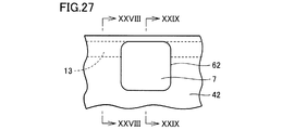
- FIG. 28 is a cross-sectional view along the line XXVIII-XXVIII in FIG. FIG.
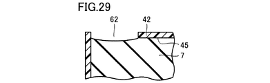
- FIG. 28 is a cross-sectional view along the line XXIX-XXIX in FIG. It is sectional drawing of the discharge device in Embodiment 9 based on this invention. It is a perspective view of the discharge device in Embodiment 10 based on this invention. It is sectional drawing of the discharge device in Embodiment 10 based on this invention.
- Embodiment 1 A discharge device according to the first embodiment of the present invention will be described with reference to FIGS. 1 to 5.
- the appearance of the discharge device 101 in the present embodiment is shown in FIG.
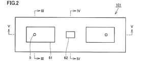
- a plan view of the discharge device 101 is shown in FIG.
- FIG. 3 shows a cross-sectional view taken along line III-III in FIG.
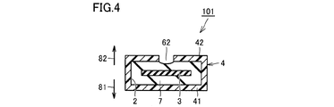
- FIG. 4 is a sectional view taken along the line IV-IV in FIG.
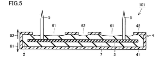
- FIG. 5 is a cross-sectional view taken along the line VV in FIG.
- the discharge device 101 includes a housing 4, a base 3, a discharge electrode 5, and an insulating sealing portion 7.
- the housing 4 is disposed so as to face the first plate 41 on the first side 41 disposed on the first side 81 and on the second side 82 opposite to the first side 81 and has a first opening. And a second plate 42 having a portion 61.
- the housing 4 defines an internal space 2 between the first plate 41 and the second plate 42.
- the substrate 3 is disposed in the internal space 2.
- the discharge electrode 5 is held by the base material 3, and the tip end portion of the discharge electrode 5 is disposed to protrude to the outside of the housing 4 through the first opening 61.
- the discharge electrode 5 is illustrated as an example of a needle electrode, but the discharge electrode 5 may be an electrode of another form.
- the insulating sealing portion 7 seals the base 3 in the internal space 2.
- the substrate 3 may be a substrate, for example, a printed wiring board.
- various components and the like disposed on or near the surface of the base material 3 are not shown, but in actuality, various components may be mounted on the surface of the base material 3.
- the second plate 42 has a second opening 62 separately from the first opening 61. The discharge electrode does not penetrate through the second opening 62.
- the bubble is the first opening at the time of resin injection for forming the insulating sealing portion 7. Not only from the portion 61 but also from the second opening 62 can be escaped. This makes it difficult for the air bubbles to stay inside the housing 4. Therefore, according to the present embodiment, it is possible to provide a discharge device in which air bubbles are unlikely to remain inside the housing 4.
- the injection of the resin is performed from the first opening 61.
- the second opening 62 is an opening exclusively for the purpose of discharging air bubbles. Although an example in which one second opening 62 is disposed at the center is described in the present embodiment, the position, number, and size of the second openings 62 may be selected as appropriate.
- the second opening 62 is an opening for the purpose of discharging air bubbles, it is preferable that not only the discharge electrode does not penetrate but also other kinds of members do not penetrate.
- first plate and “second plate” have appeared in the description so far, the “plate” mentioned here is not limited to a flat plate, but is a plate having irregularities, It is intended to include plates that are partially or entirely deformed somewhat, such as curved. Moreover, it is meant that the plate-like part in the member which the plate-like part and the part which is not plate-like connect, and becomes integral. The same applies to the following description.
- the structure described in this embodiment can be applied to a discharge device which generates ions, electrons, radicals, and the like.
- the configuration described in this embodiment can be applied to a discharge device that generates active species such as ozone.
- the ions generated by the discharge device may be only positive ions or only negative ions.
- the discharge device may generate both positive and negative ions.
- FIG. 7 is a sectional view taken along the line VII-VII in FIG.
- the discharge device in the present embodiment includes a housing 4i in place of the housing 4 shown in the first embodiment.
- the housing 4i includes a first plate 41 and a second plate 42.
- the surface of the first side 81 of the second plate 42 has a flat first region 45.
- the second opening 62 is disposed adjacent to the outer periphery of the first region 45.
- the housing 4i has a longitudinal shape whose longitudinal direction is the left and right direction in FIG. 6, and the two second openings 62 are arranged in the width direction of the housing 4i. There is.
- the second opening 62 is arranged adjacent to the outer periphery of the flat first region 45, the air bubbles are easily released from the second opening 62.
- FIG. 6 shows an example in which the pair of second openings 62 is provided, not only one pair but a plurality of pairs may be provided as shown in FIG.
- the discharge device includes a housing 4 j, and a plurality of pairs of second openings 62 are provided to be aligned in the longitudinal direction of the housing 4 j.
- the arrangement in which the pair of second openings 62 are arranged in the width direction at a specific place in the longitudinal direction of the housing as described above is merely an example.
- the second openings 62 do not have to be paired.
- the arrangement of the second openings 62 does not have to be equally spaced.
- the second openings 62 may be arranged in a staggered or irregular manner.
- the discharge device may be as shown in FIG.
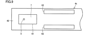
- This discharge device comprises a housing 4k. Also in the housing 4k, the second opening 62 is disposed adjacent to the outer periphery of the flat first region 45. However, in this case, the second opening 62 is a long opening along the longitudinal direction of the housing 4k.
- the discharge device may be as shown in FIG.
- This discharge device comprises a housing 4n. Also in the case 4n, the second opening 62 is disposed adjacent to the outer periphery of the flat first region 45. In this example, the second opening 62 is provided to cross the upper surface of the housing 4 n in the width direction.
- FIG. 12 shows a cross-sectional view taken along the line XII-XII in FIG.
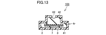
- FIG. 13 shows a cross-sectional view taken along line XIII-XIII in FIG.
- the discharge device 103 includes a housing 4r.
- the housing 4r has a step on the top surface.
- One part of the top surface is higher than the other part.
- the high part is called “high back” and the low part is called “low back”.
- the rectangular region occupying the center is the high back, and the outer edge portion is the low back.
- the positional relationship between the high back and the low back when viewed in a plan view is not limited to the example shown here.
- the second plate 42 is at the high back. Since the first opening 61 and the second opening 62 are provided in the second plate 42, both the first opening 61 and the second opening 62 are at the back.
- the configuration is the discharge device 103 in the present embodiment, the same effects as those described in the first embodiment and the like can be obtained.
- the bubbles move upward and have a high probability of coming into contact with the second high-back plate 42. Since the second plate 42 is provided with the second opening 62, the air bubbles can pass out of the housing 4r through the second opening 62.
- Embodiment 4 Fourth Embodiment A discharge device according to a fourth embodiment of the present invention will be described with reference to FIGS. A partial plan view of the discharge device 104 in the present embodiment is shown in FIG.
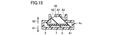
- the discharge device 104 in the present embodiment includes a housing 4 u.
- the housing 4 u two second openings 62 are provided in line along the width direction of the high back.
- FIG. 15 shows a cross-sectional view along the line XV-XV in FIG.
- the surface of the first side 81 of the second plate 42 has a flat first region 45.
- the second opening 62 is disposed adjacent to the outer periphery of the first region 45.
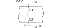
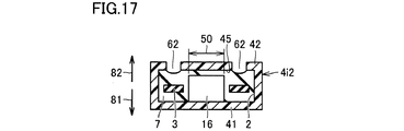
- FIGS. 16 to 17 A partial plan view of the discharge device in the present embodiment is shown in FIG. FIG. 17 shows a cross-sectional view taken along line XVII-XVII in FIG.
- This discharge device comprises a housing 4i2.
- the discharge device in the present embodiment includes component 16.
- the component 16 is disposed in the internal space 2 of the housing 4i2 to which a voltage is applied.
- the second opening 62 is arranged to avoid the area 50 where the component 16 is projected to the second plate 42.
- Component 16 may be a high voltage component.
- the second opening 62 is disposed so as to avoid the area 50 where the component 16 is projected toward the second plate 42, so that the component 16 is only covered with the insulating sealing unit 7. It will be covered by the 2nd board 42 further.
- the insulation around the component 16 can be further enhanced. Further, more reliable protection of the component 16 can be achieved.
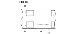
- the discharge device comprises a housing 4i3.
- the second opening 62 is provided so as to avoid the component 16 in the longitudinal direction of the housing 4i3 in plan view.
- the number of second openings 62 provided in one housing is not limited to the examples described above. When there are a plurality of second openings 62, they may be provided asymmetrically. The plurality of second openings 62 may be a combination of openings of different shapes and different sizes.
- FIG. 6 A cross-sectional view in the vicinity of the second opening 62 provided in the second plate 42 is shown in FIG.
- the second opening 62 has a straight inner circumferential surface. This may be a basic configuration, but other configurations are also conceivable.
- the second opening 62 may be, for example, as shown in FIG. In this case, the second opening 62 has an inclined inner peripheral surface. The second opening 62 extends toward the inner surface of the housing.
- the second opening 62 is a combination of a straight portion and an inclined portion.
- the side closer to the inside of the housing is inclined.
- part of the first side 81 is inclined
- part of the second side 82 is straight.
- the second opening 62 preferably includes a shape in which the first side is expanded when viewed in a cross-sectional view taken along a cross section perpendicular to the second plate 42.
- Embodiment 7 As Embodiment 7 based on this invention, the variation of the shape of the circumference
- FIG. 1 A first example of the present embodiment is shown in FIG.
- the surface of the first side 81 of the second plate has a flat first region 45 and is separated from the outer periphery of the first region 45 along at least a part of the outer periphery of the first region 45
- the slope 13 is inclined toward the first side 81 as it is.
- FIG. 15 A second example of the present embodiment is shown in FIG. In this example, along at least a part of the outer periphery of the first region 45, the curved surface 15 which continuously changes from the first region 45 and faces the first side 81 as it is separated from the outer periphery of the first region 45 is formed It is done.
- the upper surface of the housing includes a step.
- the second plate 42 raised by the step includes the first region 45 as a surface directed to the first side 81.
- a slope 13 inclined toward the first side 81 as it goes away from the outer periphery of the first region 45 is provided along at least a part of the outer periphery of the first region 45.
- the 4th example in this embodiment is not illustrated, the 4th example is the composition which replaced slope 13 in the 3rd example with curved surface 15. As shown in FIG.
- Embodiment 8 As Embodiment 8 based on this invention, the positional relationship of the slope 13 and the 2nd opening part 62 is demonstrated.
- the entire configuration may be the first example, the third example or any other configuration of the seventh embodiment. It is sufficient that the structure has the slope 13.
- FIG. 26 is a sectional view taken along line XXVI-XXVI in FIG.
- the upper end of the slope 13 and one side of the second opening 62 coincide with each other. With this configuration, the air bubbles moved upward in the figure along the slope 13 are smoothly discharged from the second opening 62.
- FIG. 28 is a sectional view taken along line XXVIII-XXVIII in FIG.
- FIG. 29 shows a sectional view taken along line XXIX-XXIX in FIG.
- the slope 13 extends along the outline of the housing.
- a second opening 62 is provided so as to cut out the middle of the extending slope 13. In this case, the air bubbles are more smoothly discharged from the second opening 62.
- FIG. 30 is a cross-sectional view when the discharge device in the present embodiment is cut in a cross section passing through the second opening 62.
- the second plate 42 of the housing thus includes a portion having a non-uniform thickness. At least a part of the lower surface of the second plate 42 is a slope 14.
- the slope 14 inclines so as to approach the first side 81 as it goes away from the second opening 62.
- the bevel 14 may be present throughout the second plate 42. In this case, the air bubbles are guided toward the second opening 62 and are more smoothly discharged from the second opening 62.
- the slope 14 is provided large, the internal space 2 is slightly narrowed. However, if there is no problem in the arrangement of objects in the internal space 2, such a configuration is also effective.
- FIG. 1 A cross-sectional view of the discharge device 110 is shown in FIG.
- the discharge device 110 includes a housing 4v and two discharge electrodes 5i.
- the housing 4 v has two first openings 61 and one second opening 62 on the top surface.
- the second opening 62 is located approximately at the center between the two first openings 61.
- the two discharge electrodes 5i are disposed to penetrate each of the two first openings 61.
- Each of the discharge electrodes 5i is a brush-like electrode.
- one of the two discharge electrodes 5i plays a role of a positive electrode and the other plays a role of a negative electrode.
- guard portions 19 are provided on the upper surface of the housing 4v. Two guard portions 19 are provided for one discharge electrode 5i, and the two guard portions 19 are disposed so as to sandwich the discharge electrode 5i.
- the guard part 19 shown here is gate-shaped. That is, the guard portion 19 includes two columnar portions rising from the upper surface of the housing 4v and a rod-like portion connecting the upper ends of the two columnar portions.
- the shape of the guard portion is not limited to the one shown here, and may be another shape.
- the card portion 19 may be integrally formed with the housing 4v. The presence of the guard part 19 is not essential. That is, the guard unit 19 may not be provided in the discharge device 110.
- the base 3 is disposed inside the housing 4v.
- Components 16 a, 16 b and 17 are mounted on the upper surface of the base 3.
- At least components 16a and 16b are components to which a high voltage is applied.
- the first opening 61 and the second opening 62 are provided at positions avoiding the components 16a and 16b.
- the components 16a, 16b, 17 are disposed on the upper surface of the base 3, but the components are not limited to the upper surface of the substrate 3, but may be disposed on the lower surface of the housing .
- the base 3 may be provided with notches or through holes as appropriate. The parts may be arranged to penetrate through the notches or through holes of the substrate 3.
- the case may have a shape other than a rectangular parallelepiped.
- the 1st opening and the 2nd opening showed the example which is a rectangle, the 1st opening may be shapes other than a rectangle.
- the second opening may have a shape other than a rectangle.
- the shape of the discharge electrode is not limited to this.
- various shapes such as rod shape, linear shape, fibrous shape, planar shape, are considered, for example.
Landscapes
- Physics & Mathematics (AREA)
- Engineering & Computer Science (AREA)
- Plasma & Fusion (AREA)
- Plasma Technology (AREA)
Abstract
放電装置(101)は、第1の側(81)に配置された第1板(41)および第1の側(81)とは逆の第2の側(82)において第1板(41)に対向するように配置されて第1開口部(61)を有する第2板(42)を含み、第1板(41)と第2板(42)との間に内部空間(2)を規定する筐体(4)と、内部空間(2)に配置される基材(3)と、基材(3)に保持され、先端部が第1開口部(61)を通って筐体(4)の外部に突出するように配置された放電電極(5)と、内部空間(2)において基材(3)を封止する絶縁封止部(7)とを備え、第2板(42)は、第1開口部(61)とは別に第2開口部(62)を有し、放電電極(5)は第2開口部(62)を貫通していない。
Description
本発明は、放電装置に関するものである。本出願は、2017年10月20日に出願した日本特許出願である特願2017-203485号に基づく優先権を主張する。当該日本特許出願に記載された全ての記載内容は、参照によって本明細書に援用される。
高電圧発生回路を構成する電子部品が樹脂でモールドされた構造の一例が特開2012-252800号公報(特許文献1)に開示されている。
針状電極を備えるイオン発生装置が、特開2015-5387号公報(特許文献2)に開示されている。
放電電極を備えるイオン発生装置が特開2017-33883号公報(特許文献3)に開示されている。放電電極はブラシ状の導電体を備える。
一般的に、特許文献1に開示されるような装置では、高電圧を発生させる回路が備えられており、高電圧が印加される部品が存在する。そのような部品は、周囲との間で異常放電が起こることによる性能低下を防ぐため、および安全性を確保するために高分子材料などでモールドされている。しかしながら、ここで用いられる高分子材料であるところの樹脂は硬化時に収縮するため、確実にモールドするためには多めに樹脂を注入する必要があり、装置の小型化の妨げになるおそれがあった。この問題を解決するための方法として、高電圧が印加される部品を筐体で覆う方法が考えられるが、その場合は気泡が表面に出にくくなる。高電圧が印加される部品の近くに気泡が残存した場合には、気泡に起因して異常放電が発生し、性能が低下してしまうおそれがあった。特に、筐体の角は気泡が溜まりやすく、特別に配慮する必要があった。放電装置の信頼性を確保し、かつ装置の小型化を図るためには、高電圧が印加される部品を筐体で覆い、かつ気泡が残りにくい構造が求められる。
本発明は、筐体の内部に気泡が残りにくい放電装置を提供することを目的とする。
上記目的を達成するため、本発明に基づく放電装置は、第1の側に配置された第1板および上記第1の側とは逆の第2の側において上記第1板に対向するように配置されて第1開口部を有する第2板を含み、上記第1板と上記第2板との間に内部空間を規定する筐体と、上記内部空間に配置される基材と、上記基材に保持され、先端部が上記第1開口部を通って上記筐体の外部に突出するように配置された放電電極と、上記内部空間において上記基材を封止する絶縁封止部とを備え、上記第2板は、上記第1開口部とは別に第2開口部を有し、上記放電電極は上記第2開口部を貫通していない。
本発明によれば、気泡は第1開口部からだけでなく第2開口部からも外に抜けることができるので、筐体の内部に気泡が残りにくい放電装置とすることができる。
(実施の形態1)
図1~図5を参照して、本発明に基づく実施の形態1における放電装置について説明する。本実施の形態における放電装置101の外観を図1に示す。放電装置101の平面図を図2に示す。図2におけるIII-III線に関する矢視断面図を図3に示す。図2におけるIV-IV線に関する矢視断面図を図4に示す。図2におけるV-V線に関する矢視断面図を図5に示す。
図1~図5を参照して、本発明に基づく実施の形態1における放電装置について説明する。本実施の形態における放電装置101の外観を図1に示す。放電装置101の平面図を図2に示す。図2におけるIII-III線に関する矢視断面図を図3に示す。図2におけるIV-IV線に関する矢視断面図を図4に示す。図2におけるV-V線に関する矢視断面図を図5に示す。
放電装置101は、筐体4と、基材3と、放電電極5と、絶縁封止部7とを備える。筐体4は、第1の側81に配置された第1板41と、第1の側81とは逆の第2の側82において第1板41に対向するように配置されて第1開口部61を有する第2板42とを含む。筐体4は、第1板41と第2板42との間に内部空間2を規定する。基材3は、内部空間2に配置される。放電電極5は、基材3に保持され、先端部が第1開口部61を通って筐体4の外部に突出するように配置されている。ここでは一例として放電電極5が針状電極であるものとして示すが、放電電極5は他の形態の電極であってもよい。絶縁封止部7は、内部空間2において基材3を封止する。基材3は基板であってよく、たとえばプリント配線基板であってよい。図3~図5では、基材3の表面または近傍に配置された各種部品などを図示省略しているが、実際には基材3の表面に各種部品が実装されていてよい。第2板42は、第1開口部61とは別に第2開口部62を有する。放電電極は第2開口部62を貫通していない。
本実施の形態では、放電電極5が貫通する第1開口部61とは別に第2開口部62が設けられているので、絶縁封止部7形成のための樹脂注入時に、気泡は第1開口部61からだけでなく第2開口部62からも外に抜けることができる。これにより、気泡は、筐体4の内部に留まりにくくなる。したがって、本実施の形態によれば、筐体4の内部に気泡が残りにくい放電装置とすることができる。
なお、樹脂の注入は第1開口部61から行なわれる。第2開口部62は専ら気泡の排出を目的とした開口部である。本実施の形態では1個の第2開口部62を中央に配置した例を示したが、第2開口部62の位置、個数、サイズは、適宜選択してよい。
第2開口部62は、気泡の排出を目的とした開口部であるので、放電電極が貫通していないということだけでなく、他の種類の部材も貫通していないことが好ましい。
なお、ここまでの説明の中で、「第1板」および「第2板」という概念が登場したが、ここでいう「板」とは平坦な板とは限らず、凹凸を有する板、一部または全部が湾曲など多少の変形をしている板を含む意である。また、板状の部分と板状でない部分とがつながって一体的となっている部材における板状の部分も含む意である。以下の説明においても同様である。
なお、本実施の形態で示した構成は、イオン、電子、ラジカルなどを発生させる放電装置に適用することができる。本実施の形態で示した構成は、オゾンなどの活性種を発生させる放電装置に適用することができる。なお、放電装置によって発生させるイオンは、正イオンのみであってもよく、負イオンのみであってもよい。放電装置は、正負イオンの両方を発生させるものであってもよい。
(実施の形態2)
図6~図7を参照して、本発明に基づく実施の形態2における放電装置について説明する。本実施の形態における放電装置の部分平面図を図6に示す。図6におけるVII-VII線に関する矢視断面図を図7に示す。
図6~図7を参照して、本発明に基づく実施の形態2における放電装置について説明する。本実施の形態における放電装置の部分平面図を図6に示す。図6におけるVII-VII線に関する矢視断面図を図7に示す。
本実施の形態における放電装置は、実施の形態1で示した筐体4に代えて筐体4iを備える。筐体4iは、第1板41と第2板42とを備える。
本実施の形態では、第2板42の第1の側81の面は、平坦な第1領域45を有する。第2開口部62は、第1領域45の外周に隣接するように配置されている。本実施の形態で示す例では、筐体4iが図6における左右方向を長手方向とする長手形状であり、2個の第2開口部62が筐体4iの幅方向に並ぶように配置されている。
筐体内部に樹脂を注入する際には、内部空間2において上方に移動し、第2板42の第1領域45に到達した気泡は、第1領域45の外周まで移動してその場に留まる確率が高い。これに対して、本実施の形態では、平坦な第1領域45の外周に隣接するように第2開口部62が配置されているので、気泡は第2開口部62から外に抜けやすくなる。
図6では、1対の第2開口部62が設けられている例を示したが、1対に限らず図8に示すように複数対設けられていてもよい。図8では、放電装置は筐体4jを備えており、筐体4jの長手方向に並ぶように複数対の第2開口部62が設けられている。このように1対の第2開口部62が筐体の長手方向のうち特定の場所で幅方向に並んでいる配置はあくまで1例である。第2開口部62は対をなしていなければならないわけではない。第2開口部62の配置は等間隔でなければならないわけではない。第2開口部62は、千鳥状に配置されてもよいし、不規則に配置されてもよい。
なお、放電装置は、図9に示すようなものであってもよい。この放電装置は筐体4kを備える。筐体4kにおいても、平坦な第1領域45の外周に隣接するように第2開口部62が配置されている。ただし、この場合、第2開口部62は筐体4kの長手方向に沿って長い開口部となっている。
放電装置は、図10に示すようなものであってもよい。この放電装置は筐体4nを備える。筐体4nにおいても、平坦な第1領域45の外周に隣接するように第2開口部62が配置されている。この例では、第2開口部62は筐体4nの上面を幅方向に横切るように設けられている。
(実施の形態3)
図11~図13を参照して、本発明に基づく実施の形態3における放電装置について説明する。本実施の形態における放電装置103の部分平面図を図11に示す。図11におけるXII-XII線に関する矢視断面図を図12に示す。図11におけるXIII-XIII線に関する矢視断面図を図13に示す。
図11~図13を参照して、本発明に基づく実施の形態3における放電装置について説明する。本実施の形態における放電装置103の部分平面図を図11に示す。図11におけるXII-XII線に関する矢視断面図を図12に示す。図11におけるXIII-XIII線に関する矢視断面図を図13に示す。
放電装置103は筐体4rを備える。筐体4rは、上面に段差を有している。上面のうち一部が他の部分に比べて高くなっている。以下では説明の便宜のため、高くなっている部分を「高背部」といい、低くなっている部分を「低背部」という。ここで示す例では、中央を占める長方形の領域が高背部となっており、それ以外の外縁部分が低背部となっている。平面図で見たときの高背部と低背部との位置関係はここで示した例に限らない。
筐体4rにおいては、第2板42は高背部にある。第1開口部61および第2開口部62は第2板42に設けられているものであるので、第1開口部61および第2開口部62はいずれも高背部にある。
本実施の形態における放電装置103のような構成であっても、実施の形態1などで説明したのと同様の効果を得ることができる。絶縁封止部7形成のために内部空間2に樹脂を注入する際には、気泡は上に移動して高背部の第2板42に当接する確率が高い。第2板42には第2開口部62が設けられているので、気泡は第2開口部62を通って筐体4rの外へ出ることができる。
なお、ここでは第1開口部61および第2開口部62はいずれも高背部にあるものとして説明したが、第1開口部61および第2開口部62のいずれかが低背部に設けられていてもよい。
(実施の形態4)
図14~図15を参照して、本発明に基づく実施の形態4における放電装置について説明する。本実施の形態における放電装置104の部分平面図を図14に示す。
図14~図15を参照して、本発明に基づく実施の形態4における放電装置について説明する。本実施の形態における放電装置104の部分平面図を図14に示す。
図14に示すように、本実施の形態における放電装置104は筐体4uを備える。筐体4uにおいては、2個の第2開口部62が高背部の幅方向に沿って並ぶように設けられている。図14におけるXV-XV線に関する矢視断面図を図15に示す。
本実施の形態においては、第2板42の第1の側81の面は、平坦な第1領域45を有する。第2開口部62は、第1領域45の外周に隣接するように配置されている。
本実施の形態における放電装置104のような構成であっても、実施の形態2などで説明したのと同様の効果を得ることができる。
(実施の形態5)
図16~図17を参照して、本発明に基づく実施の形態5における放電装置について説明する。本実施の形態における放電装置の部分平面図を図16に示す。図16におけるXVII-XVII線に関する矢視断面図を図17に示す。この放電装置は、筐体4i2を備える。
図16~図17を参照して、本発明に基づく実施の形態5における放電装置について説明する。本実施の形態における放電装置の部分平面図を図16に示す。図16におけるXVII-XVII線に関する矢視断面図を図17に示す。この放電装置は、筐体4i2を備える。
本実施の形態における放電装置は、部品16を備える。部品16は、筐体4i2の内部空間2に配置され、電圧が印加されるものである。この放電装置においては、第2開口部62は、部品16を第2板42に向けて投影した領域50を避けるように配置されている。部品16は高電圧部品であってもよい。
本実施の形態では、第2開口部62は、部品16を第2板42に向けて投影した領域50を避けるように配置されているので、部品16は絶縁封止部7で覆われるだけでなく、さらに第2板42によって覆われていることとなる。この構成を採用することにより、部品16周辺の絶縁性をより高めることができる。また、部品16のより確実な保護を図ることができる。
本実施の形態では、平面視したときに、筐体4i2の幅方向に並ぶ2つの第2開口部62が部品16を挟んでいる例を示したが、図18に示すような構成も考えられる。この例では、放電装置は筐体4i3を備える。筐体4i3においては、平面視したときに、部品16を筐体4i3の長手方向に避けるようにして第2開口部62が設けられている。
1つの筐体に設けられる第2開口部62の個数は、これまでに示した例に限らない。複数の第2開口部62がある場合に、これらは非対称に設けられていてもよい。複数の第2開口部62は、異なる形状、異なる大きさの開口部の組合せであってもよい。
(実施の形態6)
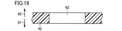
本発明に基づく実施の形態6としては、第2開口部62の詳細な形状について説明する。第2板42に設けられた第2開口部62の近傍の断面図を図19に示す。この例では、第2開口部62は、ストレート形状の内周面を有する。これが基本的な構成であってよいが、これ以外の構成も考えられる。
本発明に基づく実施の形態6としては、第2開口部62の詳細な形状について説明する。第2板42に設けられた第2開口部62の近傍の断面図を図19に示す。この例では、第2開口部62は、ストレート形状の内周面を有する。これが基本的な構成であってよいが、これ以外の構成も考えられる。
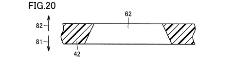
第2開口部62は、たとえば図20に示すようなものであってもよい。この場合、第2開口部62は、傾斜形状の内周面を有する。第2開口部62は、筐体の内表面に向かって広がっている。
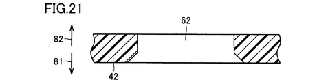
さらに、図21に示すようなものであってもよい。この場合、第2開口部62は、ストレート形状の部分と傾斜形状の部分との組合せとなっている。第2開口部62のうち筐体の内部に近い側では傾斜形状となっている。言い換えれば、第1の側81の一部は傾斜形状となっており、第2の側82の一部はストレート形状となっている。
図20、図21に示すように、第2開口部62は、第2板42に垂直な断面で切った断面図で見たとき、第1の側が広がった形状を含むことが好ましい。この構成を採用することにより、気泡を排出しやすくなる。
(実施の形態7)
本発明に基づく実施の形態7としては、筐体の第2板42の周囲の形状のバリエーションについて説明する。
本発明に基づく実施の形態7としては、筐体の第2板42の周囲の形状のバリエーションについて説明する。
(第1例)
本実施の形態における第1例を図22に示す。この例では、第2板の第1の側81の面は、平坦な第1領域45を有し、第1領域45の外周の少なくとも一部に沿うように、第1領域45の外周から離れるにつれて第1の側81に向かうように傾斜した斜面13を有する。
本実施の形態における第1例を図22に示す。この例では、第2板の第1の側81の面は、平坦な第1領域45を有し、第1領域45の外周の少なくとも一部に沿うように、第1領域45の外周から離れるにつれて第1の側81に向かうように傾斜した斜面13を有する。
(第2例)
本実施の形態における第2例を図23に示す。この例では、第1領域45の外周の少なくとも一部に沿うように、第1領域45から連続的に変化しつつ第1領域45の外周から離れるにつれて第1の側81に向かう曲面15が形成されている。
本実施の形態における第2例を図23に示す。この例では、第1領域45の外周の少なくとも一部に沿うように、第1領域45から連続的に変化しつつ第1領域45の外周から離れるにつれて第1の側81に向かう曲面15が形成されている。
(第3例)
本実施の形態における第3例を図24に示す。この例では、筐体の上面が段差を含んでいる。段差によって高くなっている第2板42が第1の側81に向く面として第1領域45を含んでいる。第1領域45の外周の少なくとも一部に沿うように、第1領域45の外周から離れるにつれて第1の側81に向かうように傾斜した斜面13を有する。
本実施の形態における第3例を図24に示す。この例では、筐体の上面が段差を含んでいる。段差によって高くなっている第2板42が第1の側81に向く面として第1領域45を含んでいる。第1領域45の外周の少なくとも一部に沿うように、第1領域45の外周から離れるにつれて第1の側81に向かうように傾斜した斜面13を有する。
(第4例)
本実施の形態における第4例は図示しないが、第4例は、第3例における斜面13を曲面15に置き換えた構成である。
本実施の形態における第4例は図示しないが、第4例は、第3例における斜面13を曲面15に置き換えた構成である。
ここで示したいくつかの例のように、斜面13または曲面15が設けられていれば、樹脂注入時に気泡は筐体4の内部に留まりにくく、気泡は第2開口部62から出やすい。したがって、本実施の形態によれば、筐体4の内部に気泡が残りにくい放電装置とすることができる。
(実施の形態8)
本発明に基づく実施の形態8としては、斜面13と第2開口部62との位置関係について説明する。全体の構成としては、実施の形態7の第1例、第3例またはそれ以外の構成であってもよい。斜面13を備える構成であればよい。
本発明に基づく実施の形態8としては、斜面13と第2開口部62との位置関係について説明する。全体の構成としては、実施の形態7の第1例、第3例またはそれ以外の構成であってもよい。斜面13を備える構成であればよい。
(第1例)
本実施の形態における第1例の平面図を図25に示す。図25におけるXXVI-XXVI線に関する矢視断面図を図26に示す。斜面13の上端と第2開口部62の1辺とが一致している。このようになっていれば、斜面13に沿って図中上方へ移動した気泡が円滑に第2開口部62から排出される。
本実施の形態における第1例の平面図を図25に示す。図25におけるXXVI-XXVI線に関する矢視断面図を図26に示す。斜面13の上端と第2開口部62の1辺とが一致している。このようになっていれば、斜面13に沿って図中上方へ移動した気泡が円滑に第2開口部62から排出される。
(第2例)
本実施の形態における第2例の平面図を図27に示す。図27におけるXXVIII-XXVIII線に関する矢視断面図を図28に示す。図27におけるXXIX-XXIX線に関する矢視断面図を図29に示す。平面視したとき、筐体の外形線に沿って斜面13が延在している。延在する斜面13の途中を切り欠くように、第2開口部62が設けられている。このようになっていれば、気泡はより円滑に第2開口部62から排出される。
本実施の形態における第2例の平面図を図27に示す。図27におけるXXVIII-XXVIII線に関する矢視断面図を図28に示す。図27におけるXXIX-XXIX線に関する矢視断面図を図29に示す。平面視したとき、筐体の外形線に沿って斜面13が延在している。延在する斜面13の途中を切り欠くように、第2開口部62が設けられている。このようになっていれば、気泡はより円滑に第2開口部62から排出される。
(実施の形態9)
図30を参照して、本発明に基づく実施の形態9における放電装置について説明する。図30は、本実施の形態における放電装置を、第2開口部62を通る断面で切ったときの断面図である。筐体の第2板42は、このように厚みが均一でない部分を含んでいる。第2板42の下面の少なくとも一部が斜面14となっている。斜面14は第2開口部62から遠ざかるにつれて第1の側81に近づくように傾斜している。斜面14は、第2板42の全体にわたって存在してもよい。このようになっていれば、気泡は第2開口部62に近づくように導かれ、より円滑に第2開口部62から排出される。斜面14を大きく設けた場合には内部空間2が若干狭くなるが、内部空間2における物の配置に支障がないならば、このような構成も有効である。
図30を参照して、本発明に基づく実施の形態9における放電装置について説明する。図30は、本実施の形態における放電装置を、第2開口部62を通る断面で切ったときの断面図である。筐体の第2板42は、このように厚みが均一でない部分を含んでいる。第2板42の下面の少なくとも一部が斜面14となっている。斜面14は第2開口部62から遠ざかるにつれて第1の側81に近づくように傾斜している。斜面14は、第2板42の全体にわたって存在してもよい。このようになっていれば、気泡は第2開口部62に近づくように導かれ、より円滑に第2開口部62から排出される。斜面14を大きく設けた場合には内部空間2が若干狭くなるが、内部空間2における物の配置に支障がないならば、このような構成も有効である。
(実施の形態10)
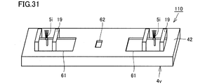
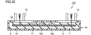
図31~図32を参照して、本発明に基づく実施の形態10における放電装置について説明する。本実施の形態における放電装置110の外観を図31に示す。放電装置110の断面図を図32に示す。放電装置110は、筐体4vと、2本の放電電極5iとを備える。筐体4vは、上面に2つの第1開口部61と1つの第2開口部62を有する。第2開口部62は2つの第1開口部61に挟まれたほぼ中央に位置する。2本の放電電極5iは、2つの第1開口部61の各々を貫通するように配置されている。放電電極5iの各々はブラシ状の電極である。たとえば、2本の放電電極5iのうち一方は正電極、他方は負電極の役割を果たす。
図31~図32を参照して、本発明に基づく実施の形態10における放電装置について説明する。本実施の形態における放電装置110の外観を図31に示す。放電装置110の断面図を図32に示す。放電装置110は、筐体4vと、2本の放電電極5iとを備える。筐体4vは、上面に2つの第1開口部61と1つの第2開口部62を有する。第2開口部62は2つの第1開口部61に挟まれたほぼ中央に位置する。2本の放電電極5iは、2つの第1開口部61の各々を貫通するように配置されている。放電電極5iの各々はブラシ状の電極である。たとえば、2本の放電電極5iのうち一方は正電極、他方は負電極の役割を果たす。
筐体4vの上面においては、いくつかのガード部19が設けられている。1つの放電電極5iに対して2つのガード部19が設けられ、2つのガード部19は放電電極5iを挟むように配置されている。ここで示すガード部19は、門形状である。すなわち、ガード部19は、筐体4vの上面から立ち上がる2本の柱状部分とこれら2本の柱状部分の上端をつなぐ棒状部分とを備える。ガード部の形状はここで示したものに限らず、他の形状であってもよい。カード部19は筐体4vと共に一体的に形成されたものであってもよい。ガード部19の存在は必須ではない。すなわち、放電装置110においてガード部19を備えないこととしてもよい。
筐体4vの内部には基材3が配置されている。基材3の上面には部品16a,16b,17が実装されている。少なくとも部品16a,16bは高電圧が印加される部品である。第1開口部61および第2開口部62は、部品16a,16bを避けた位置に設けられている。
本実施の形態では、放電装置の一例を示した。本実施の形態における放電装置においては、第2開口部62を適切な位置に設けているので、絶縁封止部7を形成するために2つの第1開口部61から樹脂を注入する際に、2つの第1開口部61の間で発生した気泡は中央の第2開口部62から排出される可能性が高まる。したがって、筐体の内部に気泡が残りにくい放電装置とすることができる。
なお、ここで示した例では、部品16a,16b,17は基材3の上面に配置されていたが、部品は基材3の上面に限らず、筐体の下面に配置されていてもよい。基材3には適宜切欠きまたは貫通孔が設けられていてもよい。部品が基材3の切欠きまたは貫通孔を貫通するように配置されてもよい。
なお、上記各実施の形態では、筐体が直方体である例を示したが、筐体は直方体以外の形状であってもよい。第1開口部および第2開口部が長方形である例を示したが、第1開口部は、長方形以外の形状であってもよい。第2開口部は、長方形以外の形状であってもよい。
これまでの各実施の形態において示した筐体の外形はあくまで一例であって、このような形状とは限らない。
これまでの実施の形態においては、放電電極が針状である場合とブラシ状である場合とについて説明したが、放電電極の形状はこれに限らない。放電電極の形状としては、たとえば棒状、線状、繊維状、面状など、さまざまな形状が考えられる。
なお、上記実施の形態のうち複数を適宜組み合わせて採用してもよい。
なお、今回開示した上記実施の形態はすべての点で例示であって制限的なものではない。本発明の範囲は請求の範囲によって示され、請求の範囲と均等の意味および範囲内でのすべての変更を含むものである。
なお、今回開示した上記実施の形態はすべての点で例示であって制限的なものではない。本発明の範囲は請求の範囲によって示され、請求の範囲と均等の意味および範囲内でのすべての変更を含むものである。
2 内部空間、3 基材、4,4i,4i2,4i3,4j,4k,4n,4r,4u,4v 筐体、5,5i 放電電極、7 絶縁封止部、13,14 斜面、15 曲面、16,16a,16b,17 部品、19 ガード部、41 第1板、42 第2板、45 第1領域、50 (投影した)領域、61 第1開口部、62 第2開口部、81 第1の側、82 第2の側、101,103,104,110 放電装置。
Claims (4)
- 第1の側に配置された第1板および前記第1の側とは逆の第2の側において前記第1板に対向するように配置されて第1開口部を有する第2板を含み、前記第1板と前記第2板との間に内部空間を規定する筐体と、
前記内部空間に配置される基材と、
前記基材に保持され、先端部が前記第1開口部を通って前記筐体の外部に突出するように配置された放電電極と、
前記内部空間において前記基材を封止する絶縁封止部とを備え、
前記第2板は、前記第1開口部とは別に第2開口部を有し、前記放電電極は前記第2開口部を貫通していない、放電装置。 - 前記第2板の前記第1の側の面は、平坦な第1領域を有し、前記第2開口部は、少なくとも前記第1領域の外周の一部に隣接するように配置されている、請求項1に記載の放電装置。
- 前記内部空間に配置され、電圧が印加される部品を備え、
前記第2開口部は、前記部品を前記第2板に向けて投影した領域を避けるように配置されている、請求項1または2に記載の放電装置。 - 前記第2開口部は、前記第2板に垂直な断面で切った断面図で見たとき、前記第1の側が広がった形状を含む、請求項1から3のいずれかに記載の放電装置。
Priority Applications (2)
| Application Number | Priority Date | Filing Date | Title |
|---|---|---|---|
| JP2019549100A JP7029466B2 (ja) | 2017-10-20 | 2018-02-20 | 放電装置 |
| CN201880067228.9A CN111213295B (zh) | 2017-10-20 | 2018-02-20 | 放电装置 |
Applications Claiming Priority (2)
| Application Number | Priority Date | Filing Date | Title |
|---|---|---|---|
| JP2017-203485 | 2017-10-20 | ||
| JP2017203485 | 2017-10-20 |
Publications (1)
| Publication Number | Publication Date |
|---|---|
| WO2019077771A1 true WO2019077771A1 (ja) | 2019-04-25 |
Family
ID=66172903
Family Applications (1)
| Application Number | Title | Priority Date | Filing Date |
|---|---|---|---|
| PCT/JP2018/006012 Ceased WO2019077771A1 (ja) | 2017-10-20 | 2018-02-20 | 放電装置 |
Country Status (4)
| Country | Link |
|---|---|
| JP (1) | JP7029466B2 (ja) |
| CN (1) | CN111213295B (ja) |
| TW (1) | TWI687008B (ja) |
| WO (1) | WO2019077771A1 (ja) |
Citations (4)
| Publication number | Priority date | Publication date | Assignee | Title |
|---|---|---|---|---|
| JP2013218807A (ja) * | 2012-04-05 | 2013-10-24 | Sharp Corp | イオン発生装置 |
| JP2015115159A (ja) * | 2013-12-11 | 2015-06-22 | シャープ株式会社 | イオン発生装置および電気機器 |
| JP2015118798A (ja) * | 2013-12-18 | 2015-06-25 | シャープ株式会社 | イオン発生装置 |
| JP2016038943A (ja) * | 2014-08-05 | 2016-03-22 | シャープ株式会社 | イオン発生装置および電気機器 |
Family Cites Families (6)
| Publication number | Priority date | Publication date | Assignee | Title |
|---|---|---|---|---|
| JP5491632B2 (ja) * | 2010-08-18 | 2014-05-14 | 京セラ株式会社 | イオン風発生体及びイオン風発生装置 |
| CN203166307U (zh) * | 2013-04-18 | 2013-08-28 | 无锡飘睿健康科技有限公司 | 一种净离子群发生装置 |
| CN105474485B (zh) * | 2013-08-20 | 2017-08-25 | 夏普株式会社 | 离子发生装置和空气调节机 |
| WO2015049920A1 (ja) * | 2013-10-01 | 2015-04-09 | シャープ株式会社 | イオン発生装置 |
| WO2015076155A1 (ja) * | 2013-11-20 | 2015-05-28 | 株式会社コガネイ | イオン発生器 |
| US9293843B2 (en) * | 2014-03-21 | 2016-03-22 | Yi Lu | Non-polarized geophysical electrode |
-
2018
- 2018-02-20 JP JP2019549100A patent/JP7029466B2/ja active Active
- 2018-02-20 CN CN201880067228.9A patent/CN111213295B/zh active Active
- 2018-02-20 WO PCT/JP2018/006012 patent/WO2019077771A1/ja not_active Ceased
- 2018-02-27 TW TW107106649A patent/TWI687008B/zh active
Patent Citations (4)
| Publication number | Priority date | Publication date | Assignee | Title |
|---|---|---|---|---|
| JP2013218807A (ja) * | 2012-04-05 | 2013-10-24 | Sharp Corp | イオン発生装置 |
| JP2015115159A (ja) * | 2013-12-11 | 2015-06-22 | シャープ株式会社 | イオン発生装置および電気機器 |
| JP2015118798A (ja) * | 2013-12-18 | 2015-06-25 | シャープ株式会社 | イオン発生装置 |
| JP2016038943A (ja) * | 2014-08-05 | 2016-03-22 | シャープ株式会社 | イオン発生装置および電気機器 |
Also Published As
| Publication number | Publication date |
|---|---|
| CN111213295B (zh) | 2021-07-27 |
| TWI687008B (zh) | 2020-03-01 |
| CN111213295A (zh) | 2020-05-29 |
| JP7029466B2 (ja) | 2022-03-03 |
| TW201917969A (zh) | 2019-05-01 |
| JPWO2019077771A1 (ja) | 2020-11-05 |
Similar Documents
| Publication | Publication Date | Title |
|---|---|---|
| KR100657092B1 (ko) | 전자기기 및 점등장치 | |
| JP6915485B2 (ja) | コンデンサおよびその製造方法 | |
| KR101270846B1 (ko) | 밀봉장치 및 밀봉 구조 | |
| WO2021193557A1 (ja) | 蓄電モジュール | |
| JP6649930B2 (ja) | 電子回路基板及び電子部品ユニット | |
| WO2012060332A1 (ja) | イオン発生装置 | |
| KR102651907B1 (ko) | 라인 밀봉부 및 진동 감쇠기 | |
| WO2019194153A1 (ja) | コンデンサ、その製造方法およびコンデンサ用の台座 | |
| US20160037690A1 (en) | Electromagnetic shield body and box | |
| US10617021B1 (en) | Electronic assembly with retention of cable | |
| WO2019077771A1 (ja) | 放電装置 | |
| US9532470B2 (en) | Resin casing | |
| JPH1022451A (ja) | 半導体装置 | |
| TWI670908B (zh) | 放電裝置 | |
| JP7391314B2 (ja) | 高電圧発生器 | |
| JP2019054296A (ja) | パワー半導体モジュール | |
| CN116137420A (zh) | 放电装置 | |
| CA3001803A1 (en) | Dust cover for electrical leads | |
| KR102226323B1 (ko) | 헤더 어셈블리 및 이를 구비하는 차량용 커넥터 장치 | |
| CN104541420A (zh) | 离子发生器和具备该离子发生器的离子发生装置 | |
| US10617020B1 (en) | Electronic assembly with retention of cable | |
| JP6623456B2 (ja) | 放電装置及びそれを用いた除電装置 | |
| JP2025032003A (ja) | コンデンサ | |
| KR20160043478A (ko) | 전자 부품 | |
| CN112449532A (zh) | 保护装置 |
Legal Events
| Date | Code | Title | Description |
|---|---|---|---|
| 121 | Ep: the epo has been informed by wipo that ep was designated in this application |
Ref document number: 18869054 Country of ref document: EP Kind code of ref document: A1 |
|
| ENP | Entry into the national phase |
Ref document number: 2019549100 Country of ref document: JP Kind code of ref document: A |
|
| NENP | Non-entry into the national phase |
Ref country code: DE |
|
| 122 | Ep: pct application non-entry in european phase |
Ref document number: 18869054 Country of ref document: EP Kind code of ref document: A1 |