WO2019077667A1 - Dispositif de détection de vibration et dispositif de détection de déséquilibre comprenant un dispositif de détection de vibration - Google Patents
Dispositif de détection de vibration et dispositif de détection de déséquilibre comprenant un dispositif de détection de vibration Download PDFInfo
- Publication number
- WO2019077667A1 WO2019077667A1 PCT/JP2017/037431 JP2017037431W WO2019077667A1 WO 2019077667 A1 WO2019077667 A1 WO 2019077667A1 JP 2017037431 W JP2017037431 W JP 2017037431W WO 2019077667 A1 WO2019077667 A1 WO 2019077667A1
- Authority
- WO
- WIPO (PCT)
- Prior art keywords
- vibration
- bearing housing
- oil flow
- lubricating oil
- forming member
- Prior art date
Links
- 238000001514 detection method Methods 0.000 title claims abstract description 78
- 239000003921 oil Substances 0.000 claims abstract description 117
- 239000010687 lubricating oil Substances 0.000 claims abstract description 62
- 230000005540 biological transmission Effects 0.000 claims abstract description 28
- NJPPVKZQTLUDBO-UHFFFAOYSA-N novaluron Chemical compound C1=C(Cl)C(OC(F)(F)C(OC(F)(F)F)F)=CC=C1NC(=O)NC(=O)C1=C(F)C=CC=C1F NJPPVKZQTLUDBO-UHFFFAOYSA-N 0.000 claims description 74
- 239000000463 material Substances 0.000 claims description 11
- 230000000149 penetrating effect Effects 0.000 claims description 4
- 230000007246 mechanism Effects 0.000 description 24
- 238000003825 pressing Methods 0.000 description 19
- 238000012546 transfer Methods 0.000 description 18
- 238000009413 insulation Methods 0.000 description 16
- 230000001133 acceleration Effects 0.000 description 9
- 239000000306 component Substances 0.000 description 7
- 238000009434 installation Methods 0.000 description 5
- 238000005259 measurement Methods 0.000 description 5
- 230000000694 effects Effects 0.000 description 4
- 230000014509 gene expression Effects 0.000 description 4
- 238000002955 isolation Methods 0.000 description 4
- 230000015572 biosynthetic process Effects 0.000 description 3
- 238000005520 cutting process Methods 0.000 description 3
- 239000008358 core component Substances 0.000 description 2
- 238000012937 correction Methods 0.000 description 2
- 238000013016 damping Methods 0.000 description 2
- 230000005484 gravity Effects 0.000 description 2
- 229910000831 Steel Inorganic materials 0.000 description 1
- 229910052782 aluminium Inorganic materials 0.000 description 1
- XAGFODPZIPBFFR-UHFFFAOYSA-N aluminium Chemical compound [Al] XAGFODPZIPBFFR-UHFFFAOYSA-N 0.000 description 1
- 238000005452 bending Methods 0.000 description 1
- 230000008859 change Effects 0.000 description 1
- 238000006243 chemical reaction Methods 0.000 description 1
- 238000006073 displacement reaction Methods 0.000 description 1
- 238000009826 distribution Methods 0.000 description 1
- 238000002474 experimental method Methods 0.000 description 1
- 239000000945 filler Substances 0.000 description 1
- 230000006872 improvement Effects 0.000 description 1
- 238000011900 installation process Methods 0.000 description 1
- 238000004519 manufacturing process Methods 0.000 description 1
- 229910052751 metal Inorganic materials 0.000 description 1
- 239000002184 metal Substances 0.000 description 1
- 238000000034 method Methods 0.000 description 1
- 239000000203 mixture Substances 0.000 description 1
- 230000008569 process Effects 0.000 description 1
- 230000009467 reduction Effects 0.000 description 1
- 238000007789 sealing Methods 0.000 description 1
- 238000004904 shortening Methods 0.000 description 1
- 238000009751 slip forming Methods 0.000 description 1
- 239000010959 steel Substances 0.000 description 1
- 238000003466 welding Methods 0.000 description 1
Images


Classifications
-
- G—PHYSICS
- G01—MEASURING; TESTING
- G01M—TESTING STATIC OR DYNAMIC BALANCE OF MACHINES OR STRUCTURES; TESTING OF STRUCTURES OR APPARATUS, NOT OTHERWISE PROVIDED FOR
- G01M1/00—Testing static or dynamic balance of machines or structures
- G01M1/14—Determining imbalance
- G01M1/16—Determining imbalance by oscillating or rotating the body to be tested
- G01M1/28—Determining imbalance by oscillating or rotating the body to be tested with special adaptations for determining imbalance of the body in situ, e.g. of vehicle wheels
-
- F—MECHANICAL ENGINEERING; LIGHTING; HEATING; WEAPONS; BLASTING
- F01—MACHINES OR ENGINES IN GENERAL; ENGINE PLANTS IN GENERAL; STEAM ENGINES
- F01D—NON-POSITIVE DISPLACEMENT MACHINES OR ENGINES, e.g. STEAM TURBINES
- F01D21/00—Shutting-down of machines or engines, e.g. in emergency; Regulating, controlling, or safety means not otherwise provided for
- F01D21/003—Arrangements for testing or measuring
-
- F—MECHANICAL ENGINEERING; LIGHTING; HEATING; WEAPONS; BLASTING
- F01—MACHINES OR ENGINES IN GENERAL; ENGINE PLANTS IN GENERAL; STEAM ENGINES
- F01D—NON-POSITIVE DISPLACEMENT MACHINES OR ENGINES, e.g. STEAM TURBINES
- F01D21/00—Shutting-down of machines or engines, e.g. in emergency; Regulating, controlling, or safety means not otherwise provided for
- F01D21/04—Shutting-down of machines or engines, e.g. in emergency; Regulating, controlling, or safety means not otherwise provided for responsive to undesired position of rotor relative to stator or to breaking-off of a part of the rotor, e.g. indicating such position
-
- F—MECHANICAL ENGINEERING; LIGHTING; HEATING; WEAPONS; BLASTING
- F01—MACHINES OR ENGINES IN GENERAL; ENGINE PLANTS IN GENERAL; STEAM ENGINES
- F01D—NON-POSITIVE DISPLACEMENT MACHINES OR ENGINES, e.g. STEAM TURBINES
- F01D21/00—Shutting-down of machines or engines, e.g. in emergency; Regulating, controlling, or safety means not otherwise provided for
- F01D21/14—Shutting-down of machines or engines, e.g. in emergency; Regulating, controlling, or safety means not otherwise provided for responsive to other specific conditions
-
- F—MECHANICAL ENGINEERING; LIGHTING; HEATING; WEAPONS; BLASTING
- F01—MACHINES OR ENGINES IN GENERAL; ENGINE PLANTS IN GENERAL; STEAM ENGINES
- F01D—NON-POSITIVE DISPLACEMENT MACHINES OR ENGINES, e.g. STEAM TURBINES
- F01D25/00—Component parts, details, or accessories, not provided for in, or of interest apart from, other groups
- F01D25/16—Arrangement of bearings; Supporting or mounting bearings in casings
-
- F—MECHANICAL ENGINEERING; LIGHTING; HEATING; WEAPONS; BLASTING
- F01—MACHINES OR ENGINES IN GENERAL; ENGINE PLANTS IN GENERAL; STEAM ENGINES
- F01D—NON-POSITIVE DISPLACEMENT MACHINES OR ENGINES, e.g. STEAM TURBINES
- F01D25/00—Component parts, details, or accessories, not provided for in, or of interest apart from, other groups
- F01D25/18—Lubricating arrangements
-
- F—MECHANICAL ENGINEERING; LIGHTING; HEATING; WEAPONS; BLASTING
- F01—MACHINES OR ENGINES IN GENERAL; ENGINE PLANTS IN GENERAL; STEAM ENGINES
- F01D—NON-POSITIVE DISPLACEMENT MACHINES OR ENGINES, e.g. STEAM TURBINES
- F01D5/00—Blades; Blade-carrying members; Heating, heat-insulating, cooling or antivibration means on the blades or the members
- F01D5/02—Blade-carrying members, e.g. rotors
- F01D5/027—Arrangements for balancing
-
- F—MECHANICAL ENGINEERING; LIGHTING; HEATING; WEAPONS; BLASTING
- F02—COMBUSTION ENGINES; HOT-GAS OR COMBUSTION-PRODUCT ENGINE PLANTS
- F02B—INTERNAL-COMBUSTION PISTON ENGINES; COMBUSTION ENGINES IN GENERAL
- F02B39/00—Component parts, details, or accessories relating to, driven charging or scavenging pumps, not provided for in groups F02B33/00 - F02B37/00
- F02B39/02—Drives of pumps; Varying pump drive gear ratio
-
- F—MECHANICAL ENGINEERING; LIGHTING; HEATING; WEAPONS; BLASTING
- F02—COMBUSTION ENGINES; HOT-GAS OR COMBUSTION-PRODUCT ENGINE PLANTS
- F02B—INTERNAL-COMBUSTION PISTON ENGINES; COMBUSTION ENGINES IN GENERAL
- F02B39/00—Component parts, details, or accessories relating to, driven charging or scavenging pumps, not provided for in groups F02B33/00 - F02B37/00
- F02B39/16—Other safety measures for, or other control of, pumps
-
- G—PHYSICS
- G01—MEASURING; TESTING
- G01H—MEASUREMENT OF MECHANICAL VIBRATIONS OR ULTRASONIC, SONIC OR INFRASONIC WAVES
- G01H1/00—Measuring characteristics of vibrations in solids by using direct conduction to the detector
- G01H1/003—Measuring characteristics of vibrations in solids by using direct conduction to the detector of rotating machines
- G01H1/006—Measuring characteristics of vibrations in solids by using direct conduction to the detector of rotating machines of the rotor of turbo machines
-
- G—PHYSICS
- G01—MEASURING; TESTING
- G01M—TESTING STATIC OR DYNAMIC BALANCE OF MACHINES OR STRUCTURES; TESTING OF STRUCTURES OR APPARATUS, NOT OTHERWISE PROVIDED FOR
- G01M1/00—Testing static or dynamic balance of machines or structures
- G01M1/14—Determining imbalance
- G01M1/16—Determining imbalance by oscillating or rotating the body to be tested
- G01M1/22—Determining imbalance by oscillating or rotating the body to be tested and converting vibrations due to imbalance into electric variables
-
- G—PHYSICS
- G01—MEASURING; TESTING
- G01M—TESTING STATIC OR DYNAMIC BALANCE OF MACHINES OR STRUCTURES; TESTING OF STRUCTURES OR APPARATUS, NOT OTHERWISE PROVIDED FOR
- G01M13/00—Testing of machine parts
- G01M13/04—Bearings
- G01M13/045—Acoustic or vibration analysis
-
- F—MECHANICAL ENGINEERING; LIGHTING; HEATING; WEAPONS; BLASTING
- F05—INDEXING SCHEMES RELATING TO ENGINES OR PUMPS IN VARIOUS SUBCLASSES OF CLASSES F01-F04
- F05D—INDEXING SCHEME FOR ASPECTS RELATING TO NON-POSITIVE-DISPLACEMENT MACHINES OR ENGINES, GAS-TURBINES OR JET-PROPULSION PLANTS
- F05D2260/00—Function
- F05D2260/96—Preventing, counteracting or reducing vibration or noise
- F05D2260/962—Preventing, counteracting or reducing vibration or noise by means of "anti-noise"
-
- F—MECHANICAL ENGINEERING; LIGHTING; HEATING; WEAPONS; BLASTING
- F05—INDEXING SCHEMES RELATING TO ENGINES OR PUMPS IN VARIOUS SUBCLASSES OF CLASSES F01-F04
- F05D—INDEXING SCHEME FOR ASPECTS RELATING TO NON-POSITIVE-DISPLACEMENT MACHINES OR ENGINES, GAS-TURBINES OR JET-PROPULSION PLANTS
- F05D2270/00—Control
- F05D2270/30—Control parameters, e.g. input parameters
- F05D2270/334—Vibration measurements
-
- F—MECHANICAL ENGINEERING; LIGHTING; HEATING; WEAPONS; BLASTING
- F05—INDEXING SCHEMES RELATING TO ENGINES OR PUMPS IN VARIOUS SUBCLASSES OF CLASSES F01-F04
- F05D—INDEXING SCHEME FOR ASPECTS RELATING TO NON-POSITIVE-DISPLACEMENT MACHINES OR ENGINES, GAS-TURBINES OR JET-PROPULSION PLANTS
- F05D2270/00—Control
- F05D2270/80—Devices generating input signals, e.g. transducers, sensors, cameras or strain gauges
- F05D2270/807—Accelerometers
-
- F—MECHANICAL ENGINEERING; LIGHTING; HEATING; WEAPONS; BLASTING
- F05—INDEXING SCHEMES RELATING TO ENGINES OR PUMPS IN VARIOUS SUBCLASSES OF CLASSES F01-F04
- F05D—INDEXING SCHEME FOR ASPECTS RELATING TO NON-POSITIVE-DISPLACEMENT MACHINES OR ENGINES, GAS-TURBINES OR JET-PROPULSION PLANTS
- F05D2270/00—Control
- F05D2270/80—Devices generating input signals, e.g. transducers, sensors, cameras or strain gauges
- F05D2270/81—Microphones
-
- F—MECHANICAL ENGINEERING; LIGHTING; HEATING; WEAPONS; BLASTING
- F16—ENGINEERING ELEMENTS AND UNITS; GENERAL MEASURES FOR PRODUCING AND MAINTAINING EFFECTIVE FUNCTIONING OF MACHINES OR INSTALLATIONS; THERMAL INSULATION IN GENERAL
- F16F—SPRINGS; SHOCK-ABSORBERS; MEANS FOR DAMPING VIBRATION
- F16F2230/00—Purpose; Design features
- F16F2230/0047—Measuring, indicating
-
- F—MECHANICAL ENGINEERING; LIGHTING; HEATING; WEAPONS; BLASTING
- F16—ENGINEERING ELEMENTS AND UNITS; GENERAL MEASURES FOR PRODUCING AND MAINTAINING EFFECTIVE FUNCTIONING OF MACHINES OR INSTALLATIONS; THERMAL INSULATION IN GENERAL
- F16F—SPRINGS; SHOCK-ABSORBERS; MEANS FOR DAMPING VIBRATION
- F16F2230/00—Purpose; Design features
- F16F2230/08—Sensor arrangement
Definitions
- the present disclosure relates to a rotating body having a wheel and a rotating shaft coupled to each other, and a bearing housing that accommodates a bearing that rotatably supports the rotating body, and a lubricating oil flow port for circulating lubricating oil inside the bearing housing.
- the present invention relates to a vibration detection device for detecting vibration of a cartridge having a bearing housing having:
- the cartridge which is a core component such as a turbocharger or an electric compressor, is subjected to a balancing operation of rotating bodies constituting the cartridge (for example, Patent Documents 1 to 4).
- This balancing operation includes an unbalance detecting operation of detecting the unbalance of the rotating body while rotating the rotating body, and when the unbalance of the rotating body is detected, a part of the rotating body is slightly scraped off It is a series of work to balance the rotating body etc.
- vibration rotational body vibration
- the unbalance detection operation while the cartridge is supported (fixed) by the unbalance detection device, air is supplied to a wheel such as a compressor wheel, for example, to create a state in which the rotating body is rotated.
- the acceleration sensor detects vibration during rotation caused by unbalance. Based on the relationship between the vibration signal detected by the acceleration sensor and the phase of the rotating body detected at the same time, the phase of the rotating body causing the vibration is specified. After this, the rotating body is scraped for balancing, but the relationship (effect vector) between the mass to be scraped (unit weight) and the change in the magnitude of vibration accompanying it is using the cartridge of the same model number (product) Obtained in advance through experiments. Then, based on the vibration signal, the phase and the effect vector (experimental result), cutting information including a mass (weight) and a position optimum for balancing of the rotating body is calculated, and the rotating body is scraped based on the cutting information.
- the acceleration sensor is installed at a portion in direct contact with the cartridge in the unbalance detection device.
- the acceleration sensor is attached to a dummy housing that fixes the cartridge.
- the unbalanced detection device directly supports the bearing housing from both sides while accommodating the turbine wheel or the compressor wheel of the rotating body using two housing members, respectively, but the acceleration sensor And the housing member directly in contact with the bearing housing.
- the efficiency of the balancing operation can be improved by installing the acceleration sensor on the unbalance detection device side, but for that purpose, the unbalance detection of the vibration at the time of rotation of the rotating body It is premised that it is transmitted well to the device side.
- the vibration at the time of rotation of the rotating body is not If the vibration sensor is installed on the side of the unbalance detection device, it is difficult to detect the vibration of the rotating body in a good manner if the vibration sensor is installed on the unbalance detection device side. And in such a case, when installing a contact type vibration sensor with respect to each cartridge, the efficiency improvement of the balancing operation is inhibited.
- At least one embodiment of the present invention aims to provide a vibration detection device capable of installing a vibration sensor for each cartridge without separately requiring a vibration sensor installation step. I assume.
- a vibration detection device for detecting vibration of a cartridge having a bearing housing, comprising: An oil flow path forming member configured to be connectable to and separated from the bearing housing, wherein the lubricating oil is supplied to the inside of the bearing housing through the lubricating oil flow port, or through the lubricating oil flow port A sensor pedestal attached to an oil flow path forming member having an oil flow path through which one of the lubricating oil discharged from the inside of the bearing housing flows; A vibration sensor installed on the sensor pedestal; And a vibration transmitting leg connected to the sensor pedestal and in contact with the bearing housing when the oil flow path forming member is connected to the bearing housing.
- the vibration sensor for detecting the vibration (rotational body vibration) generated by the rotation of the rotational body forms an oil flow path connected to the bearing housing at the time of unbalance detection operation of the rotational body
- the vibration transmitting leg attached to the member side and in contact with the bearing housing is configured to detect the rotating body vibration transmitted to the sensor pedestal.
- the oil flow path forming member is A rigid part to which the sensor pedestal is attached; A flexible body connected to the rigid portion and configured to be connectable to and separated from the bearing housing and made of a material softer than the rigid portion; The end of the oil flow passage facing the lubricating oil circulation port is formed in the flexible body portion on the surface where the oil flow passage forming member is in contact with the bearing housing in a state of being connected to the bearing housing. ing.
- the sensor pedestal can be stably attached to the oil flow channel forming member by attaching the sensor pedestal to the rigid portion of the oil flow channel forming member.
- the oil flow path forming member is configured to be able to supply the lubricating oil to the lubricating oil flow port and to discharge the lubricating oil from the lubricating oil flow port via the flexible body portion.
- the soft body portion is formed with a through hole that forms a part of the oil flow path. Therefore, while the lubricating oil is sealed along the periphery of the lubricating oil circulation port by the portion forming the oil flow passage in the flexible body so as not to leak, the vibration is transmitted from the oil flow passage forming member to the bearing housing It can be insulated.
- the oil flow path forming member is a through hole that penetrates at least the inside of the flexible body portion, and has a through hole into which the vibration transmission leg portion is inserted.
- the flexible body portion is a portion in contact with the bearing housing in the oil flow path forming member, and such a flexible body portion is provided with a through hole into which the vibration transmission leg portion is inserted.
- the oil flow path forming member extends in a first direction portion extending along a first direction orthogonal to the rotation axis, and extends along a second direction intersecting the first direction. Including two directions;
- the through hole extends along the first direction across the rigid portion and the flexible portion.
- the sensor pedestal is located on an extension of the through hole along the first direction.
- a vibration insulating member is provided between the vibration transmitting leg and the through hole formed in the rigid portion. According to the configuration of the above (5), both vibrational insulation can be performed by the vibration insulation member interposed between the vibration transmission leg portion and the through hole formed in the rigid portion. Therefore, noise components such as the vibration of the oil flow path forming member can be removed (reduced) from the signal detected by the vibration sensor, so that the detection accuracy of the rotation body vibration by the vibration sensor can be improved.
- the sensor pedestal is attached to the oil passage forming member via a second vibration insulating member.
- a second vibration insulating member it is possible to perform vibrational insulation of the both by the vibration insulating member interposed between the sensor pedestal and the oil flow passage forming member. Therefore, noise components for rotational body vibration such as vibration of the oil flow path forming member can be removed (reduced) from the signal detected by the vibration sensor, so detection accuracy of rotational body vibration by the vibration sensor can be improved.
- the vibration transfer leg has a tip end projecting with a predetermined curvature configured to contact the bearing housing. According to the configuration of the above (7), it is possible to improve the robustness at the time of contact on the tip end surface of the vibration transfer leg contacting the bearing housing.
- the unbalance detection device is A rotating body having a wheel and a rotating shaft coupled to each other, and a bearing housing accommodating a bearing for rotatably supporting the rotating body, the lubricating oil having a lubricating oil flow port for circulating lubricating oil inside the bearing housing
- An unbalance detection device for detecting vibration of a cartridge having a bearing housing comprising: An oil flow path forming member configured to be connectable to and separated from the bearing housing, wherein the lubricating oil is supplied to the inside of the bearing housing through the lubricating oil flow port, or through the lubricating oil flow port An oil flow passage forming member having an oil flow passage through which one of the lubricating oil discharged from the inside of the bearing housing flows;
- the bearing housing is connected to the sensor pedestal attached to the flow channel forming member, the vibration sensor installed on the sensor pedestal, and the sensor pedestal while being connected to the oil flow channel forming member to the bearing housing
- a vibration detection device having a vibration transmission leg that
- a vibration detection device capable of installing a vibration sensor on each cartridge without requiring an additional installation process of the vibration sensor.
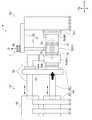
- FIG. 1 It is a figure which shows typically the unbalance detection apparatus which concerns on one Embodiment of this invention, and shows the state in which the cartridge was supported by the unbalance detection apparatus. It is a figure for demonstrating clamping and supporting the cartridge of FIG. 1 by the housing member of an unbalance detection apparatus from both sides. It is a figure which shows typically the vibration detection apparatus which concerns on one Embodiment of this invention, and is a figure which shows the separated state before connecting an oil flow path formation member to a cartridge. It is a figure which shows typically the vibration detection apparatus which concerns on one Embodiment of this invention, and is a figure which shows the state which connected the oil flow path formation member to the cartridge.
- expressions that indicate that things such as “identical”, “equal” and “homogeneous” are equal states not only represent strictly equal states, but also have tolerances or differences with which the same function can be obtained. It also represents the existing state.
- expressions representing shapes such as quadrilateral shapes and cylindrical shapes not only represent shapes such as rectangular shapes and cylindrical shapes in a geometrically strict sense, but also uneven portions and chamfers within the range where the same effect can be obtained. The shape including a part etc. shall also be expressed.
- the expressions “comprising”, “having”, “having”, “including” or “having” one component are not exclusive expressions excluding the presence of other components.
- FIG. 1 is a view schematically showing an unbalance detection device 6 used at the time of the unbalance correction work of the cartridge 5 according to an embodiment of the present invention, in which the cartridge 5 is supported by the unbalance detection device 6.
- FIG. 2 is a view for explaining that the cartridge 5 of FIG. 1 is supported by being sandwiched from both sides by the housing member 6 h of the unbalance detecting device 6.
- the cartridge 5 shown in FIGS. 1 to 2 is a core component of a turbocharger, and rotatably supports a rotating body 51 and a rotating body 51 in which a turbine wheel 53 and a compressor wheel 54 are integrally coupled by a rotating shaft 51r. And a bearing housing 52 for housing the bearing 52b. Then, when the cartridge 5 is installed in, for example, the engine of a car (not shown), the cartridge 5 is rotated by the rotation of the turbine wheel 53 installed in the exhaust passage of the engine by the exhaust gas discharged from the engine.
- a compressor wheel 54 coaxially coupled at shaft 51r is configured to rotate in the intake passage of the engine to compress intake air to the engine.
- the cartridge 5 for a turbocharger will be described as an example, but in the other embodiments, the cartridge 5 drives the compressor wheel 54 by power from a crankshaft (not shown) or an electric motor. It may be for a supercharger.
- the unbalance detection device 6 is a device for supporting the work object at the time of unbalance correction work.
- the imbalance detection device 6 is supported by sandwiching the cartridge 5 as the object to be worked by the two housing members 6h of the turbine side housing member 6t and the compressor side housing member 6c. doing. More specifically, the unbalance detecting device 6 is mounted by the support mechanism described later in a state in which the turbine wheel 53 or the compressor wheel 54 of the cartridge 5 is accommodated in the inside of the two housing members 6h (6t, 6c) described above.
- the cartridge 5 is supported by pressing at least one of the two housing members 6h toward the other.
- the unbalance detecting device 6 accommodates the rotating body 51 having the compressor wheel 54 and the rotating shaft 51r, and the bearing 52b for rotatably supporting the rotating body 51.
- the cartridge 5 comprising the bearing housing 52 is supported by being sandwiched from both sides.
- the housing member 6h supports the cartridge 5 via the vibration insulation member (support vibration insulation member 91).
- a support vibration isolation member 91 is installed between at least one of the turbine side housing member 6t and the bearing housing 52, or between the compressor side housing member 6c and the bearing housing 52.
- the vibration insulating member 91 abuts on the support receiving portion 52 p of the bearing housing 52 to support the cartridge 5.
- the support vibration insulation member 91 is interposed between the turbine side housing member 6 t and the bearing housing 52 and between the compressor side housing member 6 c and the bearing housing 52.
- the supporting vibration insulating member 91 is a member capable of achieving vibrational insulation (reduction of vibration) between the housing member 6 h and the cartridge 5, and is formed of, for example, an elastic member such as rubber. .
- the supporting vibration insulation member 91 may be a member formed of the same material as the device-side vibration insulation member 92 described later, or may be a member formed of a different material.
- the support mechanism is a compressor side support mechanism 61 connected to the compressor side housing member 6c; And a turbine-side support mechanism 62 connected to the turbine-side housing member 6t, and each support mechanism (61, 62, and so on) holds the floor of a factory or the like so as not to move when the cartridge 5 is pressed.
- the support mechanism is such that, above the floor surface, a vibration insulating member (device-side vibration insulating member 92), which is an elastic member such as rubber, is attached to the above two housing members 6h (6t, 6c; the same applies hereinafter) Connected through.
- a vibration insulating member device-side vibration insulating member 92
- a pressing device 81 is provided in the compressor-side support mechanism 61, and the pressing device 81 is configured to press the compressor-side housing member 6c toward the cartridge 5.
- the pressing device 81 includes a pressing rod 82 connected to the compressor-side housing member 6 c and a piston device 83 for pushing the pressing rod 82 toward the compressor-side housing member 6 c.
- the compressor-side housing member 6 c is pressed toward the cartridge 5 by pushing it toward the compressor-side housing member 6 c.
- the pressing device 81, the compressor-side housing member 6c, the cartridge 5, the turbine-side housing member 6t, and the turbine-side support mechanism 62 are aligned along the pressing direction (the direction of the arrow in FIG. 1).
- the pressing force by the pressing device 81 is transmitted to the turbine side support mechanism 62 by these arrangements.
- the cartridge 5 is supported by the pressing force from the pressing device 81 and the reaction force from the turbine side support mechanism 62. That is, the support mechanism supports the cartridge 5 by pressing each of the compressor-side housing member 6 c and the turbine-side housing member 6 t against the bearing housing 52.
- the pressing rod 82 and the air supply pipe 85 for guiding the air from the blower 86 to the housing member 6h are connected to each other by the connecting member 84, and the air supply is performed along with the movement of the pressing rod 82 in the pressing direction.
- the pipe 85 is also configured to be movable so as to extend and contract from the blower 86.
- the unbalance detection device 6 includes an oil flow path forming member 7 for supplying lubricating oil to the bearing 52 b accommodated in the bearing housing 52.
- the oil flow path forming member 7 is a member configured to be connectable to and separated from the bearing housing 52.
- the oil flow path forming member 7 is an oil in which the lubricating oil supplied to the inside of the bearing housing 52 flows through the lubricating oil flow port 5 a (a filler port) formed in the bearing housing 52.
- a flow path 7p is provided inside (see FIGS. 4 to 6 described later).
- the oil flow path 7p of the oil flow path forming member 7 is formed in the bearing housing 52, and after passing through the inside (bearing 52b) of the bearing housing 52, the oil flow path 7p is not shown. It may be a flow path through which the lubricating oil discharged from the inside of the bearing housing 52 through the oil port (lubricating oil flow port) flows. Then, in a state where the oil flow passage forming member 7 is connected to the bearing housing 52, the end of the oil flow passage 7p of the oil flow passage forming member 7 and the lubricating oil flow port 5a of the bearing housing 52 face each other.
- the lubricating oil may be circulated in the oil flow path 7p by the power of a pump (not shown) or the like.
- the oil flow path forming member 7 is supported by the unbalance detecting device 6 in a first direction Dg orthogonal to the rotation axis 51r of the cartridge 5 (in FIG. And a second direction Dh (in FIG. 1, a horizontal direction perpendicular to the direction of gravity), which is connected to the first direction portion 71 and extends in a direction perpendicular to the first direction Dg. And a second direction portion 72 extending along the direction).
- the unbalance detection device 6 has a movable mechanism (not shown) capable of moving the first direction portion 71 and the second direction portion 72 in both directions (up and down in FIG. 1) along the first direction Dg. ing.
- the oil flow passage forming member 7 is moved downward (in the direction of gravity) in the first direction Dg by this movable mechanism (not shown), and the lubricating oil flow opening 5a (filling opening) formed in the upper portion of the bearing housing 52
- the oil flow passage forming member 7 By connecting the oil flow passage forming member 7 to the bearing housing 52 so that the oil flow passage 7p communicates with the above, it is possible to supply lubricating oil to the bearing 52b via the oil supply port.
- the oil outlet (not shown) 5 and the oil passage 7p are communicated with each other, the oil passage forming member 7 is moved upward by the movable mechanism.
- the oil flow path forming member 7 insulates and lubricates the vibration transmitted from the member supporting the oil flow path forming member 7 (the turbine side support mechanism 62 in FIG. 1) such as vibration at the time of supply of lubricating oil.
- the vibration insulating member Connected to the bearing housing 52 in a state (pressed state) in which the vibration insulating member is pressed against the bearing housing 52 via a vibration insulating member (a flexible body 76 described later) for sealing the periphery of the oil flow port 5a Be done. That is, the oil flow path forming member 7 is connected to the rigid body portion 75 and the rigid body portion 75, and configured to be connectable to and separated from the bearing housing 52, and is formed of a softer material than the rigid body portion 75. And 76.
- the rigid portion 75 is a portion with high rigidity (Young's modulus, rigidity, etc.) excluding the soft body portion 76 in the first direction portion 71 and the second direction portion 72
- the soft body portion 76 is, for example, an elastic member such as rubber, and is a member formed of the same material as or a different material from the above-described vibration insulating members (91, 92).
- the end of the oil passage 7p facing the lubricating oil circulation port 5a is in the flexible body 76 on the surface that contacts the bearing housing 52 in a state where the oil passage forming member 7 is connected to the bearing housing 52. It is formed.
- the soft body portion 76 is formed with a through hole that forms a part of the oil flow path 7p. Therefore, in a state (pressed state) connected to the bearing housing 52, the portion forming the oil flow path 7p in the flexible body 76 seals the lubricating oil so as not to leak along the periphery of the lubricating oil flow port 5a. At the same time, insulation of vibration to be transmitted from the oil flow path forming member 7 to the bearing housing 52 is achieved.
- the unbalance detection device 6 includes the vibration detection device 1 capable of detecting a vibration (hereinafter, appropriately referred to as a rotation body vibration) generated by the rotation of the rotation body 51 provided in the cartridge 5.
- the vibration signal S detected by the vibration detection device 1 is sent to a computer (not shown) together with the phase of the rotating body 51 simultaneously detected, and cutting for correcting the unbalance of the rotating body 51 through calculation by this computer Information (described above) is obtained. Details of the vibration detection device 1 will be described later.
- the cartridge 5 is rotated in the same manner as the exhaust gas is rotated by the exhaust gas when the engine is operated.
- Detect unbalance unbalance detection work.
- air gas
- the rotating body 51 is rotated within the actual operating range of the exhaust gas while adjusting the amount of air.
- the air supply pipe 85 provided in the support mechanism and the compressor side housing member 6 c are connected via the apparatus side vibration insulation member 92, and the air blower is connected via the air supply pipe 85.
- Air from 86 is supplied to a compressor wheel 54 housed in the compressor side housing member 6c.
- the compressor side housing member 6c is connected to the air supply pipe 85 and the pressing rod 82 through the device side vibration insulation members 92 (92a and 92b), and the turbine side housing member 6t is connected to the device side vibration insulation member 92 92c) is connected to the turbine side support mechanism 62 to reduce the vibration on the side of the unbalance detection device 6 transmitted to the housing member 6h with the compressor side support mechanism 61 and the turbine side support mechanism 62 as a vibration transmission path.
- air may be supplied to the turbine wheel 53 to rotate the rotating body 51 by connecting the air supply pipe 85 and the turbine-side housing member 6t. .
- FIG. 3 is a view schematically showing the vibration detection device 1 according to the embodiment of the present invention, and is a view showing a separated state before the oil flow path forming member 7 is connected to the cartridge 5.
- FIG. 4 is a view schematically showing the vibration detection device 1 according to an embodiment of the present invention, and a view showing a state in which the oil flow path forming member 7 is connected to the cartridge 5.
- FIG. 5 is a cross-sectional view of the first direction portion 71 according to an embodiment of the present invention, showing a cross section taken along AA in FIG. FIG.
- FIG. 6 is a cross-sectional view of the second direction portion 72 according to an embodiment of the present invention, showing a cross section taken along BB in FIG.
- FIG. 7 is an enlarged view which shows the front-end
- the vibration detection device 1 includes a sensor pedestal 2, a vibration sensor 3, and a vibration transmission leg 4. The above-mentioned composition with which vibration sensing device 1 is provided is explained, respectively.
- the sensor pedestal 2 is a member on which the vibration sensor 3 is installed, and is attached to the oil flow path forming member 7 described above.
- the sensor pedestal 2 is formed of a plate-like member having a predetermined thickness, and the surface opposite to the attachment surface installed on the oil flow passage forming member 7 is A sensor installation surface 2 m on which the vibration sensor 3 is installed is configured. Further, the sensor pedestal 2 has a plurality (two in FIG. 3 to FIG. 7) of fixture through holes penetrating in the thickness direction.
- the vibration detection device 1 has the fasteners 25 (fixing screws in FIGS.
- the oil flow path By fitting (screwing) the fixing tool 25 to the engaging portion (a screw hole in FIGS. 3 to 7) formed in the forming member 7 (the rigid portion 75 described later), the sensor pedestal 2 It is fixed to the path forming member 7.
- the sensor pedestal 2 is a vibration insulating member for insulating the vibration transmitted from the oil flow path forming member 7 to the sensor pedestal 2 (seat vibration insulating member 22) Is attached to the oil passage forming member 7 via More specifically, the fixture through hole is formed across the sensor pedestal 2 and the pedestal vibration insulation member 22, and the fixture 25 is a vibration for pedestal on which the sensor pedestal 2 and the sensor pedestal 2 are installed. In a state where the insulating member 22 is penetrated, the engaging portion of the oil flow path forming member 7 is engaged. Furthermore, as shown in FIG. 3 to FIG.
- the head of the fixing screw which is the fixture 25 and the sensor pedestal 2 facing this head so that the fixture 25 and the sensor pedestal 2 do not contact
- a pedestal vibration insulating member 22 is provided between the surface 2m) and between the fixture 25 and the fixture through-hole in the sensor pedestal 2 as well.
- vibration isolation between the oil flow passage forming member 7 and the vibration detecting device 1 (sensor pedestal 2) is achieved by the vibration insulating member 22 for pedestal, and the vibration of the oil flow passage forming member 7 It is intended not to be transmitted to the sensor pedestal 2. Therefore, noise components for rotational body vibration such as vibration of the oil flow path forming member 7 can be removed (reduced) from the vibration signal S detected by the vibration sensor 3, so detection accuracy of the rotational body vibration by the vibration sensor 3 can be reduced. It can improve.
- the fixture 25 should just be able to attach the sensor base 2 to the oil flow path forming member 7, and in some other embodiments, it may be, for example, a clamp, a band material, welding, adhesion or the like.
- the vibration sensor 3 is a contact type sensor for detecting vibration, and is installed on the sensor pedestal 2.
- the vibration sensor 3 is an acceleration detection type sensor (acceleration sensor), and is fixed to the sensor pedestal 2 so that the sensor itself vibrates together with the sensor pedestal 2. It is configured to detect.
- the vibration transmitting leg 4 is connected to the sensor pedestal 2 and is in contact with the bearing housing 52 in a state where the oil flow path forming member 7 is connected to the bearing housing 52.
- the vibration transmission leg 4 may be formed of a rod-like member.
- the vibration transmission leg 4 is formed of a cylindrical member.
- one end of the vibration transfer leg portion 4 is fixedly connected to the mounting surface (described above) of the sensor pedestal 2.
- the other end (tip portion 42) of the vibration transmission leg 4 has a tip surface 42s that contacts the vibration measurement surface 52s of the bearing housing 52 in a state where the oil flow path forming member 7 is connected to the bearing housing 52.
- the sensor pedestal 2 and the bearing housing 52 are connected so as to be capable of transmitting vibration via the vibration transmitting leg 4.
- the distal end surface 42s of the vibration transmission leg 4 is on the vibration measurement surface 52s of the bearing housing 52 in a pressed state in which the flexible body 76 is pressed against the vibration measurement surface 52s of the bearing housing 52.
- the tip end surface 42s of the vibration transfer leg 4 may have a curved surface such as a hemispherical shape, and this curved surface may be configured to be in contact with the bearing housing 52.
- the vibration transmission leg 4 is constituted by three rod-like members. This makes it possible to form a stable contact state between the vibration transfer leg 4 and the bearing housing 52.
- the present invention is not limited to the present embodiment, and in some other embodiments, the vibration transmission leg 4 may be configured of one or more rod members such as one or two.
- the vibration detection device 1 includes the vibration generated in the operation range (for example, 500 to 4000 Hz) of the cartridge 5 when actually installed in a vehicle or the like, the sensor pedestal 2, the vibration sensor 3 and the vibration transmission leg 4. It is necessary to prevent resonance caused by overlapping with the natural frequency of the spring mass system to be formed. Therefore, it is necessary to make the sensor pedestal 2 as light as possible while having a thickness that can be regarded as a rigid body in the above operating range, and to make the vibration transmitting leg 4 have sufficient rigidity to support them. is there. Therefore, in the embodiment shown in FIG. 3 to FIG. 7, the longitudinal (longitudinal direction) length of the sensor pedestal 2 is referred to the outer diameter D (for example, mm) of the cylindrical first direction portion 71 (see FIG.
- the vibration transmitting leg 4 is made of a material having a high Young's modulus (for example, steel), and the sensor pedestal 2 is made of a material having a low density (for example, aluminum).
- the vibration sensor 3 detects the rotation body vibration thus transmitted to the sensor pedestal 2 by being installed on the sensor pedestal 2.
- the vibration sensor 3 for detecting the vibration (rotational body vibration) generated by the rotation of the rotational body 51 is an oil flow path connected to the bearing housing 52 at the time of unbalance detection of the rotational body 51.
- the vibration transmitting leg 4 attached to the forming member 7 side and in contact with the bearing housing 52 (the vibration measuring surface 52s) is configured to detect the rotation body vibration transmitted to the sensor pedestal 2.
- the vibration sensor 3 can be installed so as to enable appropriate detection of rotational body vibration.
- by efficiently installing the vibration sensor 3 on the bearing housing 52 it is also possible to realize the efficiency of the unbalance detection operation.
- the sensor pedestal 2 is attached to the rigid portion 75 of the oil flow path forming member 7 described above.
- the sensor pedestal 2 is attached to the upper surface of the rigid portion 75, but may be attached to the side surface of the rigid portion 75 in some other embodiments. .
- the sensor pedestal 2 can be stably attached to the oil flow passage forming member 7 by attaching the sensor pedestal 2 to the rigid portion 75 of the oil flow passage forming member 7.
- the present invention is not limited to the present embodiment.
- at least a portion of the sensor pedestal 2 may be attached to the flexible portion 76 of the oil flow path forming member 7, in which case the vibration transfer leg 4 is the same as described above. It may be linear, or may have one or more bends.
- the oil flow path forming member 7 is a through hole 73 penetrating at least the inside of the flexible body 76, and the vibration transmitting leg described above It has a through hole 73 into which 4 is inserted. That is, the through hole 73 may be formed only in the soft body portion 76, or may be formed in both the rigid portion 75 and the soft body portion 76.
- the embodiment in which the former through hole 73 is formed only in the flexible portion 76 is, for example, along the second direction Dh of a portion (for example, a portion indicated by reference numeral 71a) of the rigid portion 75 of the first direction portion 71. The length (width) is made shorter than that of the flexible body portion 76.
- the linear vibration transmitting leg 4 may be inserted and installed in the through hole 73 formed in the flexible body 76 It becomes possible.
- the vibration transmitting leg 4 has a bending portion, whereby the through hole formed in the flexible portion 76 It becomes possible to insert and install the vibration transmission leg 4 at 73.
- the sensor pedestal 2 is located on an extension of the through hole 73 along the first direction Dg. That is, the sensor pedestal 2 is installed at the upper portion thereof so as to be mounted on the oil flow path forming member 7.
- the vibration transmitting leg 4 is formed in a straight line, and in the state of being fixedly connected to the sensor pedestal 2, the through hole formed in the pedestal vibration insulating member 22 and the oil flow passage forming member 7
- the oil flow passage forming member 7 is attached in a state in which the through holes 73 formed in series with the rigid body portion 75 and the flexible body portion 76 are sequentially inserted.
- the through holes 73 of the oil flow path forming member 7 are continuously formed in the oil flow path forming member 7 in the embodiments shown in FIGS. 3 to 7, the present invention is not limited to the present embodiment.
- the through hole 73 of the oil passage forming member 7 may be composed of a plurality of portions.
- the length (width) along the second direction Dh of a portion (for example, the portion indicated by reference numeral 71a) of the rigid portion 75 of the first direction portion 71 is greater than that of the flexible body 76
- the vibration transmission leg 4 may be exposed to the outside by shortening the through hole 73 in part (the same as above). By this, it is possible to reduce a portion where the vibration transfer leg portion 4 may come into contact with the rigid portion 75, and it is possible to reduce the noise for the rotational body vibration transmitted from the rigid portion 75.
- the flexible body portion 76 is a portion in contact with the bearing housing 52 in the oil flow path forming member 7, and the through hole 73 in which the vibration transmission leg portion 4 is inserted into such a flexible body portion 76. Is provided.
- the contact between the oil flow passage forming member 7 and the bearing housing 52 can be easily realized without restriction on the space for contact of the vibration transmitting leg 4 in the bearing housing 52. be able to.
- the vibration detection device 1 may be installed so that the vibration transmission leg 4 is exposed to the outside without passing through the inside (the through hole 73) of the oil flow path forming member 7 .
- the vibration transmitting leg 4 is formed of the oil flow path forming member 7
- All of the vibration transmission legs 4 may be exposed to the outside without having a portion extending to the inside of the.
- all of the vibration transfer legs 4 may be exposed to the outside by the vibration transfer legs 4 having one or more bends.
- the sensor pedestal 2 may be installed on the upper portion of the oil flow path forming member 7, and the vibration transmitting leg portion 4 may have a bent portion which bypasses the oil flow path forming member 7. Even in such a case, since the cross-sectional area of the vibration transmission leg 4 is small, even if a space that can be the sensor pedestal 2 with which the vibration sensor 3 is in contact can not be secured in the bearing housing 52 It is possible to reduce the above-mentioned space constraints, such as securing.
- the vibration transmission leg 4 and the rigid portion 75 are formed.
- a vibration insulating member (hole vibration insulating member 77) may be provided between the through hole 73 and the through hole 73. That is, a space (annular space) is formed between the vibration transfer leg portion 4 and the through hole 73 formed in the rigid body portion 75 by having a predetermined distance between them, and a hole is formed in this space.
- a vibration insulating member 77 intervenes. In the embodiment shown in FIGS.
- the above-mentioned space between the through hole 73 of the oil flow path forming member 7 and the vibration transmitting leg 4 is filled with the hole vibration insulating member 77.
- the predetermined distance which forms said space may not be the same in all the parts.
- the hole vibration insulating member 77 may be interposed (filled) between the vibration transfer leg 4 and the through hole 73 formed in the flexible body 76.
- both of them can be vibrationally isolated by the vibration insulating member (77) interposed between the vibration transfer leg 4 and the through hole 73 formed in the rigid portion 75. Therefore, noise components such as the vibration of the oil flow passage forming member 7 can be removed (reduced) from the signal detected by the vibration sensor 3, so that the detection accuracy of the rotation body vibration by the vibration sensor 3 can be improved.
- a vibration isolation member is provided in the above space between the vibration transfer leg 4 and the rigid portion 75 or the through hole 73 formed in the rigid portion 75 and the flexible portion 76. It may not be installed and may remain as an air layer. Even in this case, it is possible to achieve vibrational insulation between the vibration transfer leg 4 and the rigid portion 75 by this space.
- the vibration transfer leg 4 has a tip surface 42 s projecting with a predetermined curvature R configured to contact the bearing housing 52.
- the curvature R is set to a value large enough to reduce the deformation of the contact point to increase the rigidity.
- the present invention is not limited to the above-described embodiments, and includes the embodiments in which the above-described embodiments are modified, and the embodiments in which these embodiments are appropriately combined.
Landscapes
- Engineering & Computer Science (AREA)
- Physics & Mathematics (AREA)
- Mechanical Engineering (AREA)
- General Engineering & Computer Science (AREA)
- General Physics & Mathematics (AREA)
- Acoustics & Sound (AREA)
- Chemical & Material Sciences (AREA)
- Combustion & Propulsion (AREA)
- Measurement Of Mechanical Vibrations Or Ultrasonic Waves (AREA)
- Testing Of Balance (AREA)
Abstract
La présente invention concerne un dispositif de détection de vibration qui est destiné à détecter la vibration d'une cartouche comportant un corps rotatif formé par assemblage d'une roue et d'un arbre rotatif et un boîtier de palier qui est destiné à loger un palier pour soutenir de façon rotative le corps rotatif et comporte un orifice d'écoulement d'huile de lubrification pour permettre à une huile de lubrification de s'écouler vers l'intérieur du boîtier de palier. Le dispositif de détection de vibration comprend : une base de capteur fixée à un élément de formation de trajet d'écoulement d'huile qui est configuré de façon à pouvoir être raccordé au boîtier de palier et retiré de celui-ci et comporte dans celui-ci un trajet d'écoulement d'huile à travers lequel s'écoule l'une parmi l'huile de lubrification distribuée à l'intérieur du boîtier de palier par l'intermédiaire de l'orifice d'écoulement d'huile de lubrification et l'huile de lubrification évacuée depuis l'intérieur du boîtier de palier par l'intermédiaire de l'orifice d'écoulement d'huile de lubrification, un capteur de vibration placé sur la base de capteur, et une patte de transmission de vibration qui est reliée à la base de capteur et est en contact avec le boîtier de palier lorsque l'élément de formation de trajet d'écoulement d'huile est relié au boîtier de palier.
Priority Applications (5)
| Application Number | Priority Date | Filing Date | Title |
|---|---|---|---|
| JP2018537558A JP6541891B1 (ja) | 2017-10-16 | 2017-10-16 | 振動検出装置、および振動検出装置を備えるアンバランス検出装置 |
| CN201780038425.3A CN109937353B (zh) | 2017-10-16 | 2017-10-16 | 振动检测装置、及具备振动检测装置的不平衡检测装置 |
| EP17912350.0A EP3502642B1 (fr) | 2017-10-16 | 2017-10-16 | Dispositif de détection de vibration et dispositif de détection de déséquilibre comprenant un dispositif de détection de vibration |
| US16/306,046 US11131596B2 (en) | 2017-10-16 | 2017-10-16 | Vibration detection device, and unbalance detection device including the vibration detection device |
| PCT/JP2017/037431 WO2019077667A1 (fr) | 2017-10-16 | 2017-10-16 | Dispositif de détection de vibration et dispositif de détection de déséquilibre comprenant un dispositif de détection de vibration |
Applications Claiming Priority (1)
| Application Number | Priority Date | Filing Date | Title |
|---|---|---|---|
| PCT/JP2017/037431 WO2019077667A1 (fr) | 2017-10-16 | 2017-10-16 | Dispositif de détection de vibration et dispositif de détection de déséquilibre comprenant un dispositif de détection de vibration |
Publications (1)
| Publication Number | Publication Date |
|---|---|
| WO2019077667A1 true WO2019077667A1 (fr) | 2019-04-25 |
Family
ID=66174058
Family Applications (1)
| Application Number | Title | Priority Date | Filing Date |
|---|---|---|---|
| PCT/JP2017/037431 WO2019077667A1 (fr) | 2017-10-16 | 2017-10-16 | Dispositif de détection de vibration et dispositif de détection de déséquilibre comprenant un dispositif de détection de vibration |
Country Status (5)
| Country | Link |
|---|---|
| US (1) | US11131596B2 (fr) |
| EP (1) | EP3502642B1 (fr) |
| JP (1) | JP6541891B1 (fr) |
| CN (1) | CN109937353B (fr) |
| WO (1) | WO2019077667A1 (fr) |
Cited By (1)
| Publication number | Priority date | Publication date | Assignee | Title |
|---|---|---|---|---|
| CN112461525A (zh) * | 2020-11-20 | 2021-03-09 | 中国直升机设计研究所 | 一种无人直升机发动机安装支架试验装置 |
Families Citing this family (3)
| Publication number | Priority date | Publication date | Assignee | Title |
|---|---|---|---|---|
| CN114136564A (zh) * | 2021-10-20 | 2022-03-04 | 中国航发四川燃气涡轮研究院 | 一种航空发动机转子轴承座的振动测试系统及测试方法 |
| CN114570670B (zh) * | 2022-05-06 | 2022-08-05 | 张家港保税区亚鑫精密制管有限公司 | 一种缩口管件缩口处强度检测工装 |
| CN117470537A (zh) * | 2023-09-26 | 2024-01-30 | 宿迁宣宸智能装备有限公司 | 一种轴承振动检测装置及检测方法 |
Citations (6)
| Publication number | Priority date | Publication date | Assignee | Title |
|---|---|---|---|---|
| JPS61217737A (ja) * | 1985-03-23 | 1986-09-27 | Ngk Insulators Ltd | タ−ボチャ−ジャ−ロ−タの回転試験方法並びにそのための装置 |
| JPH03503315A (ja) | 1988-07-25 | 1991-07-25 | アライド・シグナル・インコーポレーテツド | 高速回転部材を有する機構の力学的バランスをとる方法 |
| EP0699900A2 (fr) * | 1994-08-04 | 1996-03-06 | BALANCE SYSTEMS S.r.l. | Procédé et machine d'équilibrage pour un turbocompresseur de moteurs suralimentés |
| JP4232841B2 (ja) | 2007-07-05 | 2009-03-04 | トヨタ自動車株式会社 | 高速回転機器のアンバランス修正装置 |
| WO2015132896A1 (fr) | 2014-03-05 | 2015-09-11 | 三菱重工業株式会社 | Élément fluide rotatif et procédé de correction de déséquilibre d'un élément fluide rotatif |
| JP2016148625A (ja) | 2015-02-13 | 2016-08-18 | トヨタ自動車株式会社 | ターボチャージャーのバランシング方法 |
Family Cites Families (5)
| Publication number | Priority date | Publication date | Assignee | Title |
|---|---|---|---|---|
| JP2005133633A (ja) * | 2003-10-30 | 2005-05-26 | Matsushita Electric Ind Co Ltd | 密閉型電動圧縮機 |
| US9988976B2 (en) * | 2014-05-24 | 2018-06-05 | Honeywell International Inc. | Turbocharger |
| CN104314638A (zh) * | 2014-09-24 | 2015-01-28 | 昆山超强光电设备有限公司 | 一种压电式机油压力传感器 |
| US10233968B2 (en) * | 2015-06-04 | 2019-03-19 | Mitsubishi Heavy Industries Engine & Turbocharger, Ltd. | Bearing device and supercharger |
| CN109563829B (zh) * | 2016-08-09 | 2020-06-16 | 日本电产株式会社 | 驱动装置 |
-
2017
- 2017-10-16 EP EP17912350.0A patent/EP3502642B1/fr active Active
- 2017-10-16 JP JP2018537558A patent/JP6541891B1/ja active Active
- 2017-10-16 CN CN201780038425.3A patent/CN109937353B/zh active Active
- 2017-10-16 WO PCT/JP2017/037431 patent/WO2019077667A1/fr unknown
- 2017-10-16 US US16/306,046 patent/US11131596B2/en active Active
Patent Citations (6)
| Publication number | Priority date | Publication date | Assignee | Title |
|---|---|---|---|---|
| JPS61217737A (ja) * | 1985-03-23 | 1986-09-27 | Ngk Insulators Ltd | タ−ボチャ−ジャ−ロ−タの回転試験方法並びにそのための装置 |
| JPH03503315A (ja) | 1988-07-25 | 1991-07-25 | アライド・シグナル・インコーポレーテツド | 高速回転部材を有する機構の力学的バランスをとる方法 |
| EP0699900A2 (fr) * | 1994-08-04 | 1996-03-06 | BALANCE SYSTEMS S.r.l. | Procédé et machine d'équilibrage pour un turbocompresseur de moteurs suralimentés |
| JP4232841B2 (ja) | 2007-07-05 | 2009-03-04 | トヨタ自動車株式会社 | 高速回転機器のアンバランス修正装置 |
| WO2015132896A1 (fr) | 2014-03-05 | 2015-09-11 | 三菱重工業株式会社 | Élément fluide rotatif et procédé de correction de déséquilibre d'un élément fluide rotatif |
| JP2016148625A (ja) | 2015-02-13 | 2016-08-18 | トヨタ自動車株式会社 | ターボチャージャーのバランシング方法 |
Cited By (1)
| Publication number | Priority date | Publication date | Assignee | Title |
|---|---|---|---|---|
| CN112461525A (zh) * | 2020-11-20 | 2021-03-09 | 中国直升机设计研究所 | 一种无人直升机发动机安装支架试验装置 |
Also Published As
| Publication number | Publication date |
|---|---|
| CN109937353B (zh) | 2022-06-17 |
| EP3502642A1 (fr) | 2019-06-26 |
| EP3502642B1 (fr) | 2021-05-26 |
| JP6541891B1 (ja) | 2019-07-10 |
| JPWO2019077667A1 (ja) | 2019-11-14 |
| CN109937353A (zh) | 2019-06-25 |
| EP3502642A4 (fr) | 2019-11-06 |
| US11131596B2 (en) | 2021-09-28 |
| US20200232867A1 (en) | 2020-07-23 |
Similar Documents
| Publication | Publication Date | Title |
|---|---|---|
| JP6541891B1 (ja) | 振動検出装置、および振動検出装置を備えるアンバランス検出装置 | |
| JP6615335B2 (ja) | アンバランス検出装置、および、アンバランス検出方法 | |
| JP5120494B2 (ja) | ターボチャージャの軸受装置 | |
| US8079257B2 (en) | Method and apparatus for balancing an electrically assisted turbocharger rotor | |
| CN101144745B (zh) | 测量涡轮增压器芯部组件的旋转不平衡的装置 | |
| JP6831225B2 (ja) | 振動絶縁部材、および振動絶縁部材を備えるアンバランス検出装置 | |
| CN104160116B (zh) | 密封装置及具备密封装置的燃气涡轮 | |
| KR20130019218A (ko) | 분할구조를 갖는 에어 포일 베어링 | |
| JP6625209B2 (ja) | アンバランス検出装置、および、アンバランス検出方法 | |
| US8941279B2 (en) | Axial gap type generator | |
| WO2019102576A1 (fr) | Procédé d'élimination de vibrations de turbocompresseur, et turbocompresseur | |
| JP5332241B2 (ja) | 回転機械支持装置 | |
| JP7045470B2 (ja) | 振動絶縁保持装置 | |
| KR102251797B1 (ko) | 차량의 터보차저 밸러싱 장치 | |
| CA2445756A1 (fr) | Dispositif a turbine ou a compresseur et procede d'assemblage de ce dispositif |
Legal Events
| Date | Code | Title | Description |
|---|---|---|---|
| ENP | Entry into the national phase |
Ref document number: 2018537558 Country of ref document: JP Kind code of ref document: A |
|
| ENP | Entry into the national phase |
Ref document number: 2017912350 Country of ref document: EP Effective date: 20181212 |
|
| NENP | Non-entry into the national phase |
Ref country code: DE |