WO2019077667A1 - Vibration detection device and unbalance detection device comprising vibration detection device - Google Patents
Vibration detection device and unbalance detection device comprising vibration detection device Download PDFInfo
- Publication number
- WO2019077667A1 WO2019077667A1 PCT/JP2017/037431 JP2017037431W WO2019077667A1 WO 2019077667 A1 WO2019077667 A1 WO 2019077667A1 JP 2017037431 W JP2017037431 W JP 2017037431W WO 2019077667 A1 WO2019077667 A1 WO 2019077667A1
- Authority
- WO
- WIPO (PCT)
- Prior art keywords
- vibration
- bearing housing
- oil flow
- lubricating oil
- forming member
- Prior art date
Links
Images


Classifications
-
- G—PHYSICS
- G01—MEASURING; TESTING
- G01M—TESTING STATIC OR DYNAMIC BALANCE OF MACHINES OR STRUCTURES; TESTING OF STRUCTURES OR APPARATUS, NOT OTHERWISE PROVIDED FOR
- G01M1/00—Testing static or dynamic balance of machines or structures
- G01M1/14—Determining unbalance
- G01M1/16—Determining unbalance by oscillating or rotating the body to be tested
- G01M1/28—Determining unbalance by oscillating or rotating the body to be tested with special adaptations for determining unbalance of the body in situ, e.g. of vehicle wheels
-
- F—MECHANICAL ENGINEERING; LIGHTING; HEATING; WEAPONS; BLASTING
- F01—MACHINES OR ENGINES IN GENERAL; ENGINE PLANTS IN GENERAL; STEAM ENGINES
- F01D—NON-POSITIVE DISPLACEMENT MACHINES OR ENGINES, e.g. STEAM TURBINES
- F01D21/00—Shutting-down of machines or engines, e.g. in emergency; Regulating, controlling, or safety means not otherwise provided for
- F01D21/003—Arrangements for testing or measuring
-
- F—MECHANICAL ENGINEERING; LIGHTING; HEATING; WEAPONS; BLASTING
- F01—MACHINES OR ENGINES IN GENERAL; ENGINE PLANTS IN GENERAL; STEAM ENGINES
- F01D—NON-POSITIVE DISPLACEMENT MACHINES OR ENGINES, e.g. STEAM TURBINES
- F01D21/00—Shutting-down of machines or engines, e.g. in emergency; Regulating, controlling, or safety means not otherwise provided for
- F01D21/04—Shutting-down of machines or engines, e.g. in emergency; Regulating, controlling, or safety means not otherwise provided for responsive to undesired position of rotor relative to stator or to breaking-off of a part of the rotor, e.g. indicating such position
-
- F—MECHANICAL ENGINEERING; LIGHTING; HEATING; WEAPONS; BLASTING
- F01—MACHINES OR ENGINES IN GENERAL; ENGINE PLANTS IN GENERAL; STEAM ENGINES
- F01D—NON-POSITIVE DISPLACEMENT MACHINES OR ENGINES, e.g. STEAM TURBINES
- F01D21/00—Shutting-down of machines or engines, e.g. in emergency; Regulating, controlling, or safety means not otherwise provided for
- F01D21/14—Shutting-down of machines or engines, e.g. in emergency; Regulating, controlling, or safety means not otherwise provided for responsive to other specific conditions
-
- F—MECHANICAL ENGINEERING; LIGHTING; HEATING; WEAPONS; BLASTING
- F01—MACHINES OR ENGINES IN GENERAL; ENGINE PLANTS IN GENERAL; STEAM ENGINES
- F01D—NON-POSITIVE DISPLACEMENT MACHINES OR ENGINES, e.g. STEAM TURBINES
- F01D25/00—Component parts, details, or accessories, not provided for in, or of interest apart from, other groups
- F01D25/16—Arrangement of bearings; Supporting or mounting bearings in casings
-
- F—MECHANICAL ENGINEERING; LIGHTING; HEATING; WEAPONS; BLASTING
- F01—MACHINES OR ENGINES IN GENERAL; ENGINE PLANTS IN GENERAL; STEAM ENGINES
- F01D—NON-POSITIVE DISPLACEMENT MACHINES OR ENGINES, e.g. STEAM TURBINES
- F01D25/00—Component parts, details, or accessories, not provided for in, or of interest apart from, other groups
- F01D25/18—Lubricating arrangements
-
- F—MECHANICAL ENGINEERING; LIGHTING; HEATING; WEAPONS; BLASTING
- F01—MACHINES OR ENGINES IN GENERAL; ENGINE PLANTS IN GENERAL; STEAM ENGINES
- F01D—NON-POSITIVE DISPLACEMENT MACHINES OR ENGINES, e.g. STEAM TURBINES
- F01D5/00—Blades; Blade-carrying members; Heating, heat-insulating, cooling or antivibration means on the blades or the members
- F01D5/02—Blade-carrying members, e.g. rotors
- F01D5/027—Arrangements for balancing
-
- F—MECHANICAL ENGINEERING; LIGHTING; HEATING; WEAPONS; BLASTING
- F02—COMBUSTION ENGINES; HOT-GAS OR COMBUSTION-PRODUCT ENGINE PLANTS
- F02B—INTERNAL-COMBUSTION PISTON ENGINES; COMBUSTION ENGINES IN GENERAL
- F02B39/00—Component parts, details, or accessories relating to, driven charging or scavenging pumps, not provided for in groups F02B33/00 - F02B37/00
- F02B39/02—Drives of pumps; Varying pump drive gear ratio
-
- F—MECHANICAL ENGINEERING; LIGHTING; HEATING; WEAPONS; BLASTING
- F02—COMBUSTION ENGINES; HOT-GAS OR COMBUSTION-PRODUCT ENGINE PLANTS
- F02B—INTERNAL-COMBUSTION PISTON ENGINES; COMBUSTION ENGINES IN GENERAL
- F02B39/00—Component parts, details, or accessories relating to, driven charging or scavenging pumps, not provided for in groups F02B33/00 - F02B37/00
- F02B39/16—Other safety measures for, or other control of, pumps
-
- G—PHYSICS
- G01—MEASURING; TESTING
- G01H—MEASUREMENT OF MECHANICAL VIBRATIONS OR ULTRASONIC, SONIC OR INFRASONIC WAVES
- G01H1/00—Measuring characteristics of vibrations in solids by using direct conduction to the detector
- G01H1/003—Measuring characteristics of vibrations in solids by using direct conduction to the detector of rotating machines
- G01H1/006—Measuring characteristics of vibrations in solids by using direct conduction to the detector of rotating machines of the rotor of turbo machines
-
- G—PHYSICS
- G01—MEASURING; TESTING
- G01M—TESTING STATIC OR DYNAMIC BALANCE OF MACHINES OR STRUCTURES; TESTING OF STRUCTURES OR APPARATUS, NOT OTHERWISE PROVIDED FOR
- G01M1/00—Testing static or dynamic balance of machines or structures
- G01M1/14—Determining unbalance
- G01M1/16—Determining unbalance by oscillating or rotating the body to be tested
- G01M1/22—Determining unbalance by oscillating or rotating the body to be tested and converting vibrations due to unbalance into electric variables
-
- G—PHYSICS
- G01—MEASURING; TESTING
- G01M—TESTING STATIC OR DYNAMIC BALANCE OF MACHINES OR STRUCTURES; TESTING OF STRUCTURES OR APPARATUS, NOT OTHERWISE PROVIDED FOR
- G01M13/00—Testing of machine parts
- G01M13/04—Bearings
- G01M13/045—Acoustic or vibration analysis
-
- F—MECHANICAL ENGINEERING; LIGHTING; HEATING; WEAPONS; BLASTING
- F05—INDEXING SCHEMES RELATING TO ENGINES OR PUMPS IN VARIOUS SUBCLASSES OF CLASSES F01-F04
- F05D—INDEXING SCHEME FOR ASPECTS RELATING TO NON-POSITIVE-DISPLACEMENT MACHINES OR ENGINES, GAS-TURBINES OR JET-PROPULSION PLANTS
- F05D2260/00—Function
- F05D2260/96—Preventing, counteracting or reducing vibration or noise
- F05D2260/962—Preventing, counteracting or reducing vibration or noise by means of "anti-noise"
-
- F—MECHANICAL ENGINEERING; LIGHTING; HEATING; WEAPONS; BLASTING
- F05—INDEXING SCHEMES RELATING TO ENGINES OR PUMPS IN VARIOUS SUBCLASSES OF CLASSES F01-F04
- F05D—INDEXING SCHEME FOR ASPECTS RELATING TO NON-POSITIVE-DISPLACEMENT MACHINES OR ENGINES, GAS-TURBINES OR JET-PROPULSION PLANTS
- F05D2270/00—Control
- F05D2270/30—Control parameters, e.g. input parameters
- F05D2270/334—Vibration measurements
-
- F—MECHANICAL ENGINEERING; LIGHTING; HEATING; WEAPONS; BLASTING
- F05—INDEXING SCHEMES RELATING TO ENGINES OR PUMPS IN VARIOUS SUBCLASSES OF CLASSES F01-F04
- F05D—INDEXING SCHEME FOR ASPECTS RELATING TO NON-POSITIVE-DISPLACEMENT MACHINES OR ENGINES, GAS-TURBINES OR JET-PROPULSION PLANTS
- F05D2270/00—Control
- F05D2270/80—Devices generating input signals, e.g. transducers, sensors, cameras or strain gauges
- F05D2270/807—Accelerometers
-
- F—MECHANICAL ENGINEERING; LIGHTING; HEATING; WEAPONS; BLASTING
- F05—INDEXING SCHEMES RELATING TO ENGINES OR PUMPS IN VARIOUS SUBCLASSES OF CLASSES F01-F04
- F05D—INDEXING SCHEME FOR ASPECTS RELATING TO NON-POSITIVE-DISPLACEMENT MACHINES OR ENGINES, GAS-TURBINES OR JET-PROPULSION PLANTS
- F05D2270/00—Control
- F05D2270/80—Devices generating input signals, e.g. transducers, sensors, cameras or strain gauges
- F05D2270/81—Microphones
-
- F—MECHANICAL ENGINEERING; LIGHTING; HEATING; WEAPONS; BLASTING
- F16—ENGINEERING ELEMENTS AND UNITS; GENERAL MEASURES FOR PRODUCING AND MAINTAINING EFFECTIVE FUNCTIONING OF MACHINES OR INSTALLATIONS; THERMAL INSULATION IN GENERAL
- F16F—SPRINGS; SHOCK-ABSORBERS; MEANS FOR DAMPING VIBRATION
- F16F2230/00—Purpose; Design features
- F16F2230/0047—Measuring, indicating
-
- F—MECHANICAL ENGINEERING; LIGHTING; HEATING; WEAPONS; BLASTING
- F16—ENGINEERING ELEMENTS AND UNITS; GENERAL MEASURES FOR PRODUCING AND MAINTAINING EFFECTIVE FUNCTIONING OF MACHINES OR INSTALLATIONS; THERMAL INSULATION IN GENERAL
- F16F—SPRINGS; SHOCK-ABSORBERS; MEANS FOR DAMPING VIBRATION
- F16F2230/00—Purpose; Design features
- F16F2230/08—Sensor arrangement
Definitions
- the present disclosure relates to a rotating body having a wheel and a rotating shaft coupled to each other, and a bearing housing that accommodates a bearing that rotatably supports the rotating body, and a lubricating oil flow port for circulating lubricating oil inside the bearing housing.
- the present invention relates to a vibration detection device for detecting vibration of a cartridge having a bearing housing having:
- the cartridge which is a core component such as a turbocharger or an electric compressor, is subjected to a balancing operation of rotating bodies constituting the cartridge (for example, Patent Documents 1 to 4).
- This balancing operation includes an unbalance detecting operation of detecting the unbalance of the rotating body while rotating the rotating body, and when the unbalance of the rotating body is detected, a part of the rotating body is slightly scraped off It is a series of work to balance the rotating body etc.
- vibration rotational body vibration
- the unbalance detection operation while the cartridge is supported (fixed) by the unbalance detection device, air is supplied to a wheel such as a compressor wheel, for example, to create a state in which the rotating body is rotated.
- the acceleration sensor detects vibration during rotation caused by unbalance. Based on the relationship between the vibration signal detected by the acceleration sensor and the phase of the rotating body detected at the same time, the phase of the rotating body causing the vibration is specified. After this, the rotating body is scraped for balancing, but the relationship (effect vector) between the mass to be scraped (unit weight) and the change in the magnitude of vibration accompanying it is using the cartridge of the same model number (product) Obtained in advance through experiments. Then, based on the vibration signal, the phase and the effect vector (experimental result), cutting information including a mass (weight) and a position optimum for balancing of the rotating body is calculated, and the rotating body is scraped based on the cutting information.
- the acceleration sensor is installed at a portion in direct contact with the cartridge in the unbalance detection device.
- the acceleration sensor is attached to a dummy housing that fixes the cartridge.
- the unbalanced detection device directly supports the bearing housing from both sides while accommodating the turbine wheel or the compressor wheel of the rotating body using two housing members, respectively, but the acceleration sensor And the housing member directly in contact with the bearing housing.
- the efficiency of the balancing operation can be improved by installing the acceleration sensor on the unbalance detection device side, but for that purpose, the unbalance detection of the vibration at the time of rotation of the rotating body It is premised that it is transmitted well to the device side.
- the vibration at the time of rotation of the rotating body is not If the vibration sensor is installed on the side of the unbalance detection device, it is difficult to detect the vibration of the rotating body in a good manner if the vibration sensor is installed on the unbalance detection device side. And in such a case, when installing a contact type vibration sensor with respect to each cartridge, the efficiency improvement of the balancing operation is inhibited.
- At least one embodiment of the present invention aims to provide a vibration detection device capable of installing a vibration sensor for each cartridge without separately requiring a vibration sensor installation step. I assume.
- a vibration detection device for detecting vibration of a cartridge having a bearing housing, comprising: An oil flow path forming member configured to be connectable to and separated from the bearing housing, wherein the lubricating oil is supplied to the inside of the bearing housing through the lubricating oil flow port, or through the lubricating oil flow port A sensor pedestal attached to an oil flow path forming member having an oil flow path through which one of the lubricating oil discharged from the inside of the bearing housing flows; A vibration sensor installed on the sensor pedestal; And a vibration transmitting leg connected to the sensor pedestal and in contact with the bearing housing when the oil flow path forming member is connected to the bearing housing.
- the vibration sensor for detecting the vibration (rotational body vibration) generated by the rotation of the rotational body forms an oil flow path connected to the bearing housing at the time of unbalance detection operation of the rotational body
- the vibration transmitting leg attached to the member side and in contact with the bearing housing is configured to detect the rotating body vibration transmitted to the sensor pedestal.
- the oil flow path forming member is A rigid part to which the sensor pedestal is attached; A flexible body connected to the rigid portion and configured to be connectable to and separated from the bearing housing and made of a material softer than the rigid portion; The end of the oil flow passage facing the lubricating oil circulation port is formed in the flexible body portion on the surface where the oil flow passage forming member is in contact with the bearing housing in a state of being connected to the bearing housing. ing.
- the sensor pedestal can be stably attached to the oil flow channel forming member by attaching the sensor pedestal to the rigid portion of the oil flow channel forming member.
- the oil flow path forming member is configured to be able to supply the lubricating oil to the lubricating oil flow port and to discharge the lubricating oil from the lubricating oil flow port via the flexible body portion.
- the soft body portion is formed with a through hole that forms a part of the oil flow path. Therefore, while the lubricating oil is sealed along the periphery of the lubricating oil circulation port by the portion forming the oil flow passage in the flexible body so as not to leak, the vibration is transmitted from the oil flow passage forming member to the bearing housing It can be insulated.
- the oil flow path forming member is a through hole that penetrates at least the inside of the flexible body portion, and has a through hole into which the vibration transmission leg portion is inserted.
- the flexible body portion is a portion in contact with the bearing housing in the oil flow path forming member, and such a flexible body portion is provided with a through hole into which the vibration transmission leg portion is inserted.
- the oil flow path forming member extends in a first direction portion extending along a first direction orthogonal to the rotation axis, and extends along a second direction intersecting the first direction. Including two directions;
- the through hole extends along the first direction across the rigid portion and the flexible portion.
- the sensor pedestal is located on an extension of the through hole along the first direction.
- a vibration insulating member is provided between the vibration transmitting leg and the through hole formed in the rigid portion. According to the configuration of the above (5), both vibrational insulation can be performed by the vibration insulation member interposed between the vibration transmission leg portion and the through hole formed in the rigid portion. Therefore, noise components such as the vibration of the oil flow path forming member can be removed (reduced) from the signal detected by the vibration sensor, so that the detection accuracy of the rotation body vibration by the vibration sensor can be improved.
- the sensor pedestal is attached to the oil passage forming member via a second vibration insulating member.
- a second vibration insulating member it is possible to perform vibrational insulation of the both by the vibration insulating member interposed between the sensor pedestal and the oil flow passage forming member. Therefore, noise components for rotational body vibration such as vibration of the oil flow path forming member can be removed (reduced) from the signal detected by the vibration sensor, so detection accuracy of rotational body vibration by the vibration sensor can be improved.
- the vibration transfer leg has a tip end projecting with a predetermined curvature configured to contact the bearing housing. According to the configuration of the above (7), it is possible to improve the robustness at the time of contact on the tip end surface of the vibration transfer leg contacting the bearing housing.
- the unbalance detection device is A rotating body having a wheel and a rotating shaft coupled to each other, and a bearing housing accommodating a bearing for rotatably supporting the rotating body, the lubricating oil having a lubricating oil flow port for circulating lubricating oil inside the bearing housing
- An unbalance detection device for detecting vibration of a cartridge having a bearing housing comprising: An oil flow path forming member configured to be connectable to and separated from the bearing housing, wherein the lubricating oil is supplied to the inside of the bearing housing through the lubricating oil flow port, or through the lubricating oil flow port An oil flow passage forming member having an oil flow passage through which one of the lubricating oil discharged from the inside of the bearing housing flows;
- the bearing housing is connected to the sensor pedestal attached to the flow channel forming member, the vibration sensor installed on the sensor pedestal, and the sensor pedestal while being connected to the oil flow channel forming member to the bearing housing
- a vibration detection device having a vibration transmission leg that
- a vibration detection device capable of installing a vibration sensor on each cartridge without requiring an additional installation process of the vibration sensor.
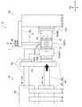
- FIG. 1 It is a figure which shows typically the unbalance detection apparatus which concerns on one Embodiment of this invention, and shows the state in which the cartridge was supported by the unbalance detection apparatus. It is a figure for demonstrating clamping and supporting the cartridge of FIG. 1 by the housing member of an unbalance detection apparatus from both sides. It is a figure which shows typically the vibration detection apparatus which concerns on one Embodiment of this invention, and is a figure which shows the separated state before connecting an oil flow path formation member to a cartridge. It is a figure which shows typically the vibration detection apparatus which concerns on one Embodiment of this invention, and is a figure which shows the state which connected the oil flow path formation member to the cartridge.
- expressions that indicate that things such as “identical”, “equal” and “homogeneous” are equal states not only represent strictly equal states, but also have tolerances or differences with which the same function can be obtained. It also represents the existing state.
- expressions representing shapes such as quadrilateral shapes and cylindrical shapes not only represent shapes such as rectangular shapes and cylindrical shapes in a geometrically strict sense, but also uneven portions and chamfers within the range where the same effect can be obtained. The shape including a part etc. shall also be expressed.
- the expressions “comprising”, “having”, “having”, “including” or “having” one component are not exclusive expressions excluding the presence of other components.
- FIG. 1 is a view schematically showing an unbalance detection device 6 used at the time of the unbalance correction work of the cartridge 5 according to an embodiment of the present invention, in which the cartridge 5 is supported by the unbalance detection device 6.
- FIG. 2 is a view for explaining that the cartridge 5 of FIG. 1 is supported by being sandwiched from both sides by the housing member 6 h of the unbalance detecting device 6.
- the cartridge 5 shown in FIGS. 1 to 2 is a core component of a turbocharger, and rotatably supports a rotating body 51 and a rotating body 51 in which a turbine wheel 53 and a compressor wheel 54 are integrally coupled by a rotating shaft 51r. And a bearing housing 52 for housing the bearing 52b. Then, when the cartridge 5 is installed in, for example, the engine of a car (not shown), the cartridge 5 is rotated by the rotation of the turbine wheel 53 installed in the exhaust passage of the engine by the exhaust gas discharged from the engine.
- a compressor wheel 54 coaxially coupled at shaft 51r is configured to rotate in the intake passage of the engine to compress intake air to the engine.
- the cartridge 5 for a turbocharger will be described as an example, but in the other embodiments, the cartridge 5 drives the compressor wheel 54 by power from a crankshaft (not shown) or an electric motor. It may be for a supercharger.
- the unbalance detection device 6 is a device for supporting the work object at the time of unbalance correction work.
- the imbalance detection device 6 is supported by sandwiching the cartridge 5 as the object to be worked by the two housing members 6h of the turbine side housing member 6t and the compressor side housing member 6c. doing. More specifically, the unbalance detecting device 6 is mounted by the support mechanism described later in a state in which the turbine wheel 53 or the compressor wheel 54 of the cartridge 5 is accommodated in the inside of the two housing members 6h (6t, 6c) described above.
- the cartridge 5 is supported by pressing at least one of the two housing members 6h toward the other.
- the unbalance detecting device 6 accommodates the rotating body 51 having the compressor wheel 54 and the rotating shaft 51r, and the bearing 52b for rotatably supporting the rotating body 51.
- the cartridge 5 comprising the bearing housing 52 is supported by being sandwiched from both sides.
- the housing member 6h supports the cartridge 5 via the vibration insulation member (support vibration insulation member 91).
- a support vibration isolation member 91 is installed between at least one of the turbine side housing member 6t and the bearing housing 52, or between the compressor side housing member 6c and the bearing housing 52.
- the vibration insulating member 91 abuts on the support receiving portion 52 p of the bearing housing 52 to support the cartridge 5.
- the support vibration insulation member 91 is interposed between the turbine side housing member 6 t and the bearing housing 52 and between the compressor side housing member 6 c and the bearing housing 52.
- the supporting vibration insulating member 91 is a member capable of achieving vibrational insulation (reduction of vibration) between the housing member 6 h and the cartridge 5, and is formed of, for example, an elastic member such as rubber. .
- the supporting vibration insulation member 91 may be a member formed of the same material as the device-side vibration insulation member 92 described later, or may be a member formed of a different material.
- the support mechanism is a compressor side support mechanism 61 connected to the compressor side housing member 6c; And a turbine-side support mechanism 62 connected to the turbine-side housing member 6t, and each support mechanism (61, 62, and so on) holds the floor of a factory or the like so as not to move when the cartridge 5 is pressed.
- the support mechanism is such that, above the floor surface, a vibration insulating member (device-side vibration insulating member 92), which is an elastic member such as rubber, is attached to the above two housing members 6h (6t, 6c; the same applies hereinafter) Connected through.
- a vibration insulating member device-side vibration insulating member 92
- a pressing device 81 is provided in the compressor-side support mechanism 61, and the pressing device 81 is configured to press the compressor-side housing member 6c toward the cartridge 5.
- the pressing device 81 includes a pressing rod 82 connected to the compressor-side housing member 6 c and a piston device 83 for pushing the pressing rod 82 toward the compressor-side housing member 6 c.
- the compressor-side housing member 6 c is pressed toward the cartridge 5 by pushing it toward the compressor-side housing member 6 c.
- the pressing device 81, the compressor-side housing member 6c, the cartridge 5, the turbine-side housing member 6t, and the turbine-side support mechanism 62 are aligned along the pressing direction (the direction of the arrow in FIG. 1).
- the pressing force by the pressing device 81 is transmitted to the turbine side support mechanism 62 by these arrangements.
- the cartridge 5 is supported by the pressing force from the pressing device 81 and the reaction force from the turbine side support mechanism 62. That is, the support mechanism supports the cartridge 5 by pressing each of the compressor-side housing member 6 c and the turbine-side housing member 6 t against the bearing housing 52.
- the pressing rod 82 and the air supply pipe 85 for guiding the air from the blower 86 to the housing member 6h are connected to each other by the connecting member 84, and the air supply is performed along with the movement of the pressing rod 82 in the pressing direction.
- the pipe 85 is also configured to be movable so as to extend and contract from the blower 86.
- the unbalance detection device 6 includes an oil flow path forming member 7 for supplying lubricating oil to the bearing 52 b accommodated in the bearing housing 52.
- the oil flow path forming member 7 is a member configured to be connectable to and separated from the bearing housing 52.
- the oil flow path forming member 7 is an oil in which the lubricating oil supplied to the inside of the bearing housing 52 flows through the lubricating oil flow port 5 a (a filler port) formed in the bearing housing 52.
- a flow path 7p is provided inside (see FIGS. 4 to 6 described later).
- the oil flow path 7p of the oil flow path forming member 7 is formed in the bearing housing 52, and after passing through the inside (bearing 52b) of the bearing housing 52, the oil flow path 7p is not shown. It may be a flow path through which the lubricating oil discharged from the inside of the bearing housing 52 through the oil port (lubricating oil flow port) flows. Then, in a state where the oil flow passage forming member 7 is connected to the bearing housing 52, the end of the oil flow passage 7p of the oil flow passage forming member 7 and the lubricating oil flow port 5a of the bearing housing 52 face each other.
- the lubricating oil may be circulated in the oil flow path 7p by the power of a pump (not shown) or the like.
- the oil flow path forming member 7 is supported by the unbalance detecting device 6 in a first direction Dg orthogonal to the rotation axis 51r of the cartridge 5 (in FIG. And a second direction Dh (in FIG. 1, a horizontal direction perpendicular to the direction of gravity), which is connected to the first direction portion 71 and extends in a direction perpendicular to the first direction Dg. And a second direction portion 72 extending along the direction).
- the unbalance detection device 6 has a movable mechanism (not shown) capable of moving the first direction portion 71 and the second direction portion 72 in both directions (up and down in FIG. 1) along the first direction Dg. ing.
- the oil flow passage forming member 7 is moved downward (in the direction of gravity) in the first direction Dg by this movable mechanism (not shown), and the lubricating oil flow opening 5a (filling opening) formed in the upper portion of the bearing housing 52
- the oil flow passage forming member 7 By connecting the oil flow passage forming member 7 to the bearing housing 52 so that the oil flow passage 7p communicates with the above, it is possible to supply lubricating oil to the bearing 52b via the oil supply port.
- the oil outlet (not shown) 5 and the oil passage 7p are communicated with each other, the oil passage forming member 7 is moved upward by the movable mechanism.
- the oil flow path forming member 7 insulates and lubricates the vibration transmitted from the member supporting the oil flow path forming member 7 (the turbine side support mechanism 62 in FIG. 1) such as vibration at the time of supply of lubricating oil.
- the vibration insulating member Connected to the bearing housing 52 in a state (pressed state) in which the vibration insulating member is pressed against the bearing housing 52 via a vibration insulating member (a flexible body 76 described later) for sealing the periphery of the oil flow port 5a Be done. That is, the oil flow path forming member 7 is connected to the rigid body portion 75 and the rigid body portion 75, and configured to be connectable to and separated from the bearing housing 52, and is formed of a softer material than the rigid body portion 75. And 76.
- the rigid portion 75 is a portion with high rigidity (Young's modulus, rigidity, etc.) excluding the soft body portion 76 in the first direction portion 71 and the second direction portion 72
- the soft body portion 76 is, for example, an elastic member such as rubber, and is a member formed of the same material as or a different material from the above-described vibration insulating members (91, 92).
- the end of the oil passage 7p facing the lubricating oil circulation port 5a is in the flexible body 76 on the surface that contacts the bearing housing 52 in a state where the oil passage forming member 7 is connected to the bearing housing 52. It is formed.
- the soft body portion 76 is formed with a through hole that forms a part of the oil flow path 7p. Therefore, in a state (pressed state) connected to the bearing housing 52, the portion forming the oil flow path 7p in the flexible body 76 seals the lubricating oil so as not to leak along the periphery of the lubricating oil flow port 5a. At the same time, insulation of vibration to be transmitted from the oil flow path forming member 7 to the bearing housing 52 is achieved.
- the unbalance detection device 6 includes the vibration detection device 1 capable of detecting a vibration (hereinafter, appropriately referred to as a rotation body vibration) generated by the rotation of the rotation body 51 provided in the cartridge 5.
- the vibration signal S detected by the vibration detection device 1 is sent to a computer (not shown) together with the phase of the rotating body 51 simultaneously detected, and cutting for correcting the unbalance of the rotating body 51 through calculation by this computer Information (described above) is obtained. Details of the vibration detection device 1 will be described later.
- the cartridge 5 is rotated in the same manner as the exhaust gas is rotated by the exhaust gas when the engine is operated.
- Detect unbalance unbalance detection work.
- air gas
- the rotating body 51 is rotated within the actual operating range of the exhaust gas while adjusting the amount of air.
- the air supply pipe 85 provided in the support mechanism and the compressor side housing member 6 c are connected via the apparatus side vibration insulation member 92, and the air blower is connected via the air supply pipe 85.
- Air from 86 is supplied to a compressor wheel 54 housed in the compressor side housing member 6c.
- the compressor side housing member 6c is connected to the air supply pipe 85 and the pressing rod 82 through the device side vibration insulation members 92 (92a and 92b), and the turbine side housing member 6t is connected to the device side vibration insulation member 92 92c) is connected to the turbine side support mechanism 62 to reduce the vibration on the side of the unbalance detection device 6 transmitted to the housing member 6h with the compressor side support mechanism 61 and the turbine side support mechanism 62 as a vibration transmission path.
- air may be supplied to the turbine wheel 53 to rotate the rotating body 51 by connecting the air supply pipe 85 and the turbine-side housing member 6t. .
- FIG. 3 is a view schematically showing the vibration detection device 1 according to the embodiment of the present invention, and is a view showing a separated state before the oil flow path forming member 7 is connected to the cartridge 5.
- FIG. 4 is a view schematically showing the vibration detection device 1 according to an embodiment of the present invention, and a view showing a state in which the oil flow path forming member 7 is connected to the cartridge 5.
- FIG. 5 is a cross-sectional view of the first direction portion 71 according to an embodiment of the present invention, showing a cross section taken along AA in FIG. FIG.
- FIG. 6 is a cross-sectional view of the second direction portion 72 according to an embodiment of the present invention, showing a cross section taken along BB in FIG.
- FIG. 7 is an enlarged view which shows the front-end
- the vibration detection device 1 includes a sensor pedestal 2, a vibration sensor 3, and a vibration transmission leg 4. The above-mentioned composition with which vibration sensing device 1 is provided is explained, respectively.
- the sensor pedestal 2 is a member on which the vibration sensor 3 is installed, and is attached to the oil flow path forming member 7 described above.
- the sensor pedestal 2 is formed of a plate-like member having a predetermined thickness, and the surface opposite to the attachment surface installed on the oil flow passage forming member 7 is A sensor installation surface 2 m on which the vibration sensor 3 is installed is configured. Further, the sensor pedestal 2 has a plurality (two in FIG. 3 to FIG. 7) of fixture through holes penetrating in the thickness direction.
- the vibration detection device 1 has the fasteners 25 (fixing screws in FIGS.
- the oil flow path By fitting (screwing) the fixing tool 25 to the engaging portion (a screw hole in FIGS. 3 to 7) formed in the forming member 7 (the rigid portion 75 described later), the sensor pedestal 2 It is fixed to the path forming member 7.
- the sensor pedestal 2 is a vibration insulating member for insulating the vibration transmitted from the oil flow path forming member 7 to the sensor pedestal 2 (seat vibration insulating member 22) Is attached to the oil passage forming member 7 via More specifically, the fixture through hole is formed across the sensor pedestal 2 and the pedestal vibration insulation member 22, and the fixture 25 is a vibration for pedestal on which the sensor pedestal 2 and the sensor pedestal 2 are installed. In a state where the insulating member 22 is penetrated, the engaging portion of the oil flow path forming member 7 is engaged. Furthermore, as shown in FIG. 3 to FIG.
- the head of the fixing screw which is the fixture 25 and the sensor pedestal 2 facing this head so that the fixture 25 and the sensor pedestal 2 do not contact
- a pedestal vibration insulating member 22 is provided between the surface 2m) and between the fixture 25 and the fixture through-hole in the sensor pedestal 2 as well.
- vibration isolation between the oil flow passage forming member 7 and the vibration detecting device 1 (sensor pedestal 2) is achieved by the vibration insulating member 22 for pedestal, and the vibration of the oil flow passage forming member 7 It is intended not to be transmitted to the sensor pedestal 2. Therefore, noise components for rotational body vibration such as vibration of the oil flow path forming member 7 can be removed (reduced) from the vibration signal S detected by the vibration sensor 3, so detection accuracy of the rotational body vibration by the vibration sensor 3 can be reduced. It can improve.
- the fixture 25 should just be able to attach the sensor base 2 to the oil flow path forming member 7, and in some other embodiments, it may be, for example, a clamp, a band material, welding, adhesion or the like.
- the vibration sensor 3 is a contact type sensor for detecting vibration, and is installed on the sensor pedestal 2.
- the vibration sensor 3 is an acceleration detection type sensor (acceleration sensor), and is fixed to the sensor pedestal 2 so that the sensor itself vibrates together with the sensor pedestal 2. It is configured to detect.
- the vibration transmitting leg 4 is connected to the sensor pedestal 2 and is in contact with the bearing housing 52 in a state where the oil flow path forming member 7 is connected to the bearing housing 52.
- the vibration transmission leg 4 may be formed of a rod-like member.
- the vibration transmission leg 4 is formed of a cylindrical member.
- one end of the vibration transfer leg portion 4 is fixedly connected to the mounting surface (described above) of the sensor pedestal 2.
- the other end (tip portion 42) of the vibration transmission leg 4 has a tip surface 42s that contacts the vibration measurement surface 52s of the bearing housing 52 in a state where the oil flow path forming member 7 is connected to the bearing housing 52.
- the sensor pedestal 2 and the bearing housing 52 are connected so as to be capable of transmitting vibration via the vibration transmitting leg 4.
- the distal end surface 42s of the vibration transmission leg 4 is on the vibration measurement surface 52s of the bearing housing 52 in a pressed state in which the flexible body 76 is pressed against the vibration measurement surface 52s of the bearing housing 52.
- the tip end surface 42s of the vibration transfer leg 4 may have a curved surface such as a hemispherical shape, and this curved surface may be configured to be in contact with the bearing housing 52.
- the vibration transmission leg 4 is constituted by three rod-like members. This makes it possible to form a stable contact state between the vibration transfer leg 4 and the bearing housing 52.
- the present invention is not limited to the present embodiment, and in some other embodiments, the vibration transmission leg 4 may be configured of one or more rod members such as one or two.
- the vibration detection device 1 includes the vibration generated in the operation range (for example, 500 to 4000 Hz) of the cartridge 5 when actually installed in a vehicle or the like, the sensor pedestal 2, the vibration sensor 3 and the vibration transmission leg 4. It is necessary to prevent resonance caused by overlapping with the natural frequency of the spring mass system to be formed. Therefore, it is necessary to make the sensor pedestal 2 as light as possible while having a thickness that can be regarded as a rigid body in the above operating range, and to make the vibration transmitting leg 4 have sufficient rigidity to support them. is there. Therefore, in the embodiment shown in FIG. 3 to FIG. 7, the longitudinal (longitudinal direction) length of the sensor pedestal 2 is referred to the outer diameter D (for example, mm) of the cylindrical first direction portion 71 (see FIG.
- the vibration transmitting leg 4 is made of a material having a high Young's modulus (for example, steel), and the sensor pedestal 2 is made of a material having a low density (for example, aluminum).
- the vibration sensor 3 detects the rotation body vibration thus transmitted to the sensor pedestal 2 by being installed on the sensor pedestal 2.
- the vibration sensor 3 for detecting the vibration (rotational body vibration) generated by the rotation of the rotational body 51 is an oil flow path connected to the bearing housing 52 at the time of unbalance detection of the rotational body 51.
- the vibration transmitting leg 4 attached to the forming member 7 side and in contact with the bearing housing 52 (the vibration measuring surface 52s) is configured to detect the rotation body vibration transmitted to the sensor pedestal 2.
- the vibration sensor 3 can be installed so as to enable appropriate detection of rotational body vibration.
- by efficiently installing the vibration sensor 3 on the bearing housing 52 it is also possible to realize the efficiency of the unbalance detection operation.
- the sensor pedestal 2 is attached to the rigid portion 75 of the oil flow path forming member 7 described above.
- the sensor pedestal 2 is attached to the upper surface of the rigid portion 75, but may be attached to the side surface of the rigid portion 75 in some other embodiments. .
- the sensor pedestal 2 can be stably attached to the oil flow passage forming member 7 by attaching the sensor pedestal 2 to the rigid portion 75 of the oil flow passage forming member 7.
- the present invention is not limited to the present embodiment.
- at least a portion of the sensor pedestal 2 may be attached to the flexible portion 76 of the oil flow path forming member 7, in which case the vibration transfer leg 4 is the same as described above. It may be linear, or may have one or more bends.
- the oil flow path forming member 7 is a through hole 73 penetrating at least the inside of the flexible body 76, and the vibration transmitting leg described above It has a through hole 73 into which 4 is inserted. That is, the through hole 73 may be formed only in the soft body portion 76, or may be formed in both the rigid portion 75 and the soft body portion 76.
- the embodiment in which the former through hole 73 is formed only in the flexible portion 76 is, for example, along the second direction Dh of a portion (for example, a portion indicated by reference numeral 71a) of the rigid portion 75 of the first direction portion 71. The length (width) is made shorter than that of the flexible body portion 76.
- the linear vibration transmitting leg 4 may be inserted and installed in the through hole 73 formed in the flexible body 76 It becomes possible.
- the vibration transmitting leg 4 has a bending portion, whereby the through hole formed in the flexible portion 76 It becomes possible to insert and install the vibration transmission leg 4 at 73.
- the sensor pedestal 2 is located on an extension of the through hole 73 along the first direction Dg. That is, the sensor pedestal 2 is installed at the upper portion thereof so as to be mounted on the oil flow path forming member 7.
- the vibration transmitting leg 4 is formed in a straight line, and in the state of being fixedly connected to the sensor pedestal 2, the through hole formed in the pedestal vibration insulating member 22 and the oil flow passage forming member 7
- the oil flow passage forming member 7 is attached in a state in which the through holes 73 formed in series with the rigid body portion 75 and the flexible body portion 76 are sequentially inserted.
- the through holes 73 of the oil flow path forming member 7 are continuously formed in the oil flow path forming member 7 in the embodiments shown in FIGS. 3 to 7, the present invention is not limited to the present embodiment.
- the through hole 73 of the oil passage forming member 7 may be composed of a plurality of portions.
- the length (width) along the second direction Dh of a portion (for example, the portion indicated by reference numeral 71a) of the rigid portion 75 of the first direction portion 71 is greater than that of the flexible body 76
- the vibration transmission leg 4 may be exposed to the outside by shortening the through hole 73 in part (the same as above). By this, it is possible to reduce a portion where the vibration transfer leg portion 4 may come into contact with the rigid portion 75, and it is possible to reduce the noise for the rotational body vibration transmitted from the rigid portion 75.
- the flexible body portion 76 is a portion in contact with the bearing housing 52 in the oil flow path forming member 7, and the through hole 73 in which the vibration transmission leg portion 4 is inserted into such a flexible body portion 76. Is provided.
- the contact between the oil flow passage forming member 7 and the bearing housing 52 can be easily realized without restriction on the space for contact of the vibration transmitting leg 4 in the bearing housing 52. be able to.
- the vibration detection device 1 may be installed so that the vibration transmission leg 4 is exposed to the outside without passing through the inside (the through hole 73) of the oil flow path forming member 7 .
- the vibration transmitting leg 4 is formed of the oil flow path forming member 7
- All of the vibration transmission legs 4 may be exposed to the outside without having a portion extending to the inside of the.
- all of the vibration transfer legs 4 may be exposed to the outside by the vibration transfer legs 4 having one or more bends.
- the sensor pedestal 2 may be installed on the upper portion of the oil flow path forming member 7, and the vibration transmitting leg portion 4 may have a bent portion which bypasses the oil flow path forming member 7. Even in such a case, since the cross-sectional area of the vibration transmission leg 4 is small, even if a space that can be the sensor pedestal 2 with which the vibration sensor 3 is in contact can not be secured in the bearing housing 52 It is possible to reduce the above-mentioned space constraints, such as securing.
- the vibration transmission leg 4 and the rigid portion 75 are formed.
- a vibration insulating member (hole vibration insulating member 77) may be provided between the through hole 73 and the through hole 73. That is, a space (annular space) is formed between the vibration transfer leg portion 4 and the through hole 73 formed in the rigid body portion 75 by having a predetermined distance between them, and a hole is formed in this space.
- a vibration insulating member 77 intervenes. In the embodiment shown in FIGS.
- the above-mentioned space between the through hole 73 of the oil flow path forming member 7 and the vibration transmitting leg 4 is filled with the hole vibration insulating member 77.
- the predetermined distance which forms said space may not be the same in all the parts.
- the hole vibration insulating member 77 may be interposed (filled) between the vibration transfer leg 4 and the through hole 73 formed in the flexible body 76.
- both of them can be vibrationally isolated by the vibration insulating member (77) interposed between the vibration transfer leg 4 and the through hole 73 formed in the rigid portion 75. Therefore, noise components such as the vibration of the oil flow passage forming member 7 can be removed (reduced) from the signal detected by the vibration sensor 3, so that the detection accuracy of the rotation body vibration by the vibration sensor 3 can be improved.
- a vibration isolation member is provided in the above space between the vibration transfer leg 4 and the rigid portion 75 or the through hole 73 formed in the rigid portion 75 and the flexible portion 76. It may not be installed and may remain as an air layer. Even in this case, it is possible to achieve vibrational insulation between the vibration transfer leg 4 and the rigid portion 75 by this space.
- the vibration transfer leg 4 has a tip surface 42 s projecting with a predetermined curvature R configured to contact the bearing housing 52.
- the curvature R is set to a value large enough to reduce the deformation of the contact point to increase the rigidity.
- the present invention is not limited to the above-described embodiments, and includes the embodiments in which the above-described embodiments are modified, and the embodiments in which these embodiments are appropriately combined.
Abstract
This vibration detection device is for detecting the vibration of a cartridge having a rotating body formed by joining a wheel and a rotary shaft and a bearing housing that is for accommodating a bearing for rotatably supporting the rotating body and has a lubricating oil flow port for allowing a lubricating oil to flow to the inside of the bearing housing. The vibration detection device comprises: a sensor base attached to an oil-flow-path forming member that is configured so as to be capable of being connected to and removed from the bearing housing and has therein an oil flow path through which flows one from among the lubricating oil supplied to the inside of the bearing housing via the lubricating oil flow port and the lubricating oil discharged from the inside of the bearing housing via the lubricating oil flow port, a vibration sensor placed on the sensor base, and a vibration transmission leg that is connected to the sensor base and touches the bearing housing when the oil-flow-path forming member is connected to the bearing housing.
Description
本開示は、ホイールと回転軸とを結合した回転体、および回転体を回転可能に支持するベアリングを収容するベアリングハウジングであって、ベアリングハウジングの内部に潤滑油を流通させるための潤滑油流通口を有するベアリングハウジングを有するカートリッジの振動を検出するための振動検出装置に関する。
The present disclosure relates to a rotating body having a wheel and a rotating shaft coupled to each other, and a bearing housing that accommodates a bearing that rotatably supports the rotating body, and a lubricating oil flow port for circulating lubricating oil inside the bearing housing. The present invention relates to a vibration detection device for detecting vibration of a cartridge having a bearing housing having:
ターボチャージャや電動コンプレッサなどの中核部品であるカートリッジは、その組立後に、カートリッジを構成する回転体のバランシング作業が行われる(例えば、特許文献1~4)。このバランシング作業は、回転体を回転させた状態で回転体のアンバランスを検出するアンバランス検出作業を含んでおり、回転体のアンバランスを検出した際には回転体の一部をわずかに削るなどして回転体をバランシングさせる一連の作業である。製造時において回転体のバランシング作業を行うことにより、エンジンの運転時において高速回転する回転体のアンバランスに起因した回転時の振動(回転体振動)や、この振動に伴う騒音、破損などの防止が図られる。
After assembling, the cartridge, which is a core component such as a turbocharger or an electric compressor, is subjected to a balancing operation of rotating bodies constituting the cartridge (for example, Patent Documents 1 to 4). This balancing operation includes an unbalance detecting operation of detecting the unbalance of the rotating body while rotating the rotating body, and when the unbalance of the rotating body is detected, a part of the rotating body is slightly scraped off It is a series of work to balance the rotating body etc. By balancing the rotating body at the time of manufacturing, it is possible to prevent vibration (rotational body vibration) during rotation caused by imbalance of the rotating body rotating at high speed during operation of the engine, noise and damage caused by this vibration Is taken.
より詳細には、アンバランス検出作業では、アンバランス検出装置でカートリッジを支持(固定)しつつ、例えばコンプレッサホイールなどのホイールに空気を供給して回転体を回転させた状態を作り、回転体のアンバランスに起因して生じる回転時の振動を加速度センサで検出する。この加速度センサで検出した振動信号と、これと同時に検出した回転体の位相との関係に基づいて、振動を生じさせている回転体の位相を特定する。この後、バランシングさせるために回転体を削ることになるが、削られる質量(単位ウエイト)とそれに伴う振動の大きさなどの変化の関係(効果ベクトル)は同一型番(製品)のカートリッジを用いて予め実験を通して取得しておく。そして、上記の振動信号、位相および効果ベクトル(実験結果)に基づいて、回転体のバランシングに最適な質量(ウエイト)や位置を含む切削情報を計算し、切削情報に基づいて回転体を削る。
More specifically, in the unbalance detection operation, while the cartridge is supported (fixed) by the unbalance detection device, air is supplied to a wheel such as a compressor wheel, for example, to create a state in which the rotating body is rotated. The acceleration sensor detects vibration during rotation caused by unbalance. Based on the relationship between the vibration signal detected by the acceleration sensor and the phase of the rotating body detected at the same time, the phase of the rotating body causing the vibration is specified. After this, the rotating body is scraped for balancing, but the relationship (effect vector) between the mass to be scraped (unit weight) and the change in the magnitude of vibration accompanying it is using the cartridge of the same model number (product) Obtained in advance through experiments. Then, based on the vibration signal, the phase and the effect vector (experimental result), cutting information including a mass (weight) and a position optimum for balancing of the rotating body is calculated, and the rotating body is scraped based on the cutting information.
例えば特許文献2~4では、加速度センサは、アンバランス検出装置におけるカートリッジと直接接触する部位に設置されている。具体的には、特許文献2では、加速度センサは、カートリッジを固定するダミーハウジングに取り付けられている。特許文献3~4では、アンバランス検出装置は、2つのハウジング部材を用いて、回転体のタービンホイールあるいはコンプレッサホイールをそれぞれ収容しながら、ベアリングハウジングを両側から直接支持するが、加速度センサは、このようなベアリングハウジングに直接接触するハウジング部材に設置されている。これによって、大量生産されるターボカートリッジの個体の各々をアンバランス検出装置に設置するたびに、各々の個体に対して加速度センサを設置する工程を別途行う必要がなく、バランシング作業におけるセンサ設置作業を効率化しつつ、回転体の振動の良好な検出を可能としている。
For example, in Patent Documents 2 to 4, the acceleration sensor is installed at a portion in direct contact with the cartridge in the unbalance detection device. Specifically, in Patent Document 2, the acceleration sensor is attached to a dummy housing that fixes the cartridge. In Patent Documents 3 to 4, the unbalanced detection device directly supports the bearing housing from both sides while accommodating the turbine wheel or the compressor wheel of the rotating body using two housing members, respectively, but the acceleration sensor And the housing member directly in contact with the bearing housing. By this, it is not necessary to separately perform the process of installing an acceleration sensor for each individual, each time the individual of the mass-produced turbo cartridges are installed in the unbalance detection device, and the sensor installation operation in the balancing operation can be performed. While improving efficiency, good detection of vibration of the rotating body is enabled.
上述した特許文献2~4のように、加速度センサをアンバランス検出装置側に設置することによりバランシング作業の効率化が可能であるが、そのためには、回転体の回転時の振動をアンバランス検出装置側に良好に伝達させることが前提になる。しかしながら、例えば、本発明の発明者らが別途提案するように、アンバランス検出装置のハウジング部材が振動絶縁部材を介してカートリッジを支持する場合(後述)など、回転体の回転時の振動がアンバランス検出装置側に良好に伝達されないような形態では、アンバランス検出装置側に振動センサを設置しても、回転体の回転時の振動を良好な検出は難しい。そして、このような場合において、各カートリッジに対して接触型の振動センサを設置する場合には、バランシング作業の効率化が阻害される。
As described in Patent Documents 2 to 4 above, the efficiency of the balancing operation can be improved by installing the acceleration sensor on the unbalance detection device side, but for that purpose, the unbalance detection of the vibration at the time of rotation of the rotating body It is premised that it is transmitted well to the device side. However, for example, as the inventors of the present invention separately propose, when the housing member of the unbalance detection device supports the cartridge via the vibration insulating member (described later), the vibration at the time of rotation of the rotating body is not If the vibration sensor is installed on the side of the unbalance detection device, it is difficult to detect the vibration of the rotating body in a good manner if the vibration sensor is installed on the unbalance detection device side. And in such a case, when installing a contact type vibration sensor with respect to each cartridge, the efficiency improvement of the balancing operation is inhibited.
上述の事情に鑑みて、本発明の少なくとも一実施形態は、振動センサの設置工程を別途要することなく、各カートリッジに対して振動センサを設置することが可能な振動検出装置を提供することを目的とする。
In view of the above-described circumstances, at least one embodiment of the present invention aims to provide a vibration detection device capable of installing a vibration sensor for each cartridge without separately requiring a vibration sensor installation step. I assume.
(1)本発明の少なくとも一実施形態に係る振動検出装置は、
ホイールと回転軸とを結合した回転体、および前記回転体を回転可能に支持するベアリングを収容するベアリングハウジングであって、前記ベアリングハウジングの内部に潤滑油を流通させるための潤滑油流通口を有するベアリングハウジング、を有するカートリッジの振動を検出するための振動検出装置であって、
前記ベアリングハウジングに接続および離間可能に構成される油流路形成部材であって、前記潤滑油流通口を介して前記ベアリングハウジングの内部へ供給される潤滑油、または前記潤滑油流通口を介して前記ベアリングハウジングの内部から排出される潤滑油の一方が流れる油流路を内部に有する油流路形成部材に取り付けられるセンサ台座と、
前記センサ台座に設置される振動センサと、
前記センサ台座に接続されると共に、前記油流路形成部材が前記ベアリングハウジングに接続された状態において前記ベアリングハウジングに接触される振動伝達脚部と、を備える。 (1) A vibration detection device according to at least one embodiment of the present invention,
A rotating body having a wheel and a rotating shaft coupled to each other, and a bearing housing accommodating a bearing for rotatably supporting the rotating body, the lubricating oil having a lubricating oil flow port for circulating lubricating oil inside the bearing housing A vibration detection device for detecting vibration of a cartridge having a bearing housing, comprising:
An oil flow path forming member configured to be connectable to and separated from the bearing housing, wherein the lubricating oil is supplied to the inside of the bearing housing through the lubricating oil flow port, or through the lubricating oil flow port A sensor pedestal attached to an oil flow path forming member having an oil flow path through which one of the lubricating oil discharged from the inside of the bearing housing flows;
A vibration sensor installed on the sensor pedestal;
And a vibration transmitting leg connected to the sensor pedestal and in contact with the bearing housing when the oil flow path forming member is connected to the bearing housing.
上記(1)の構成によれば、回転体の回転により生じる振動(回転体振動)を検出するための振動センサは、回転体のアンバランス検出作業時においてベアリングハウジングに接続される油流路形成部材側に取り付けられると共に、ベアリングハウジングに接触した振動伝達脚部によってセンサ台座に伝達された回転体振動を検出するように構成される。これによって、カートリッジ側にセンサ台座を設ける必要がなく、かつ、アンバランス検出作業時において振動センサを設置する作業を別途行うことなく、ベアリングハウジングに油流路形成部材を接続することにより、回転体振動の適切な検出が可能となるように振動センサを設置することができる。このように、ベアリングハウジングに対する振動センサの設置が効率化されることによって、アンバランス検出作業の効率化を実現することもできる。
According to the configuration of (1), the vibration sensor for detecting the vibration (rotational body vibration) generated by the rotation of the rotational body forms an oil flow path connected to the bearing housing at the time of unbalance detection operation of the rotational body The vibration transmitting leg attached to the member side and in contact with the bearing housing is configured to detect the rotating body vibration transmitted to the sensor pedestal. As a result, there is no need to provide a sensor pedestal on the cartridge side, and the rotating body can be connected by connecting the oil flow path forming member to the bearing housing without separately installing the vibration sensor at the time of unbalance detection. A vibration sensor can be installed to enable proper detection of vibration. Thus, the efficiency of the unbalance detection operation can also be realized by the efficient installation of the vibration sensor to the bearing housing.
(2)幾つかの実施形態では、上記(1)の構成において、
前記油流路形成部材は、
前記センサ台座が取り付けられる剛体部と、
前記剛体部に接続されると共に、前記ベアリングハウジングに接続および離間可能に構成され、前記剛体部よりも柔らかい材料から形成される柔体部と、を含み、
前記柔体部には、前記油流路形成部材が前記ベアリングハウジングに接続された状態で前記ベアリングハウジングに当接する面において、前記潤滑油流通口に面する前記油流路の端部が形成されている。
上記(2)の構成によれば、センサ台座を油流路形成部材の剛体部に取り付けることにより、センサ台座を油流路形成部材に安定して取り付けることができる。また、油流路形成部材は、柔体部を介して、潤滑油を潤滑油流通口に供給したり、潤滑油流通口から潤滑油を排出したりすることが可能に構成される。換言すれば、柔体部には油流路の一部を形成する貫通孔が形成されている。よって、柔体部における油流路を形成する部分によって潤滑油流通口の周囲を伝って潤滑油が漏れないようにシールしつつ、油流路形成部材からベアリングハウジングに伝達されようとする振動の絶縁を図ることができる。 (2) In some embodiments, in the configuration of (1) above,
The oil flow path forming member is
A rigid part to which the sensor pedestal is attached;
A flexible body connected to the rigid portion and configured to be connectable to and separated from the bearing housing and made of a material softer than the rigid portion;
The end of the oil flow passage facing the lubricating oil circulation port is formed in the flexible body portion on the surface where the oil flow passage forming member is in contact with the bearing housing in a state of being connected to the bearing housing. ing.
According to the configuration of (2), the sensor pedestal can be stably attached to the oil flow channel forming member by attaching the sensor pedestal to the rigid portion of the oil flow channel forming member. Further, the oil flow path forming member is configured to be able to supply the lubricating oil to the lubricating oil flow port and to discharge the lubricating oil from the lubricating oil flow port via the flexible body portion. In other words, the soft body portion is formed with a through hole that forms a part of the oil flow path. Therefore, while the lubricating oil is sealed along the periphery of the lubricating oil circulation port by the portion forming the oil flow passage in the flexible body so as not to leak, the vibration is transmitted from the oil flow passage forming member to the bearing housing It can be insulated.
(3)幾つかの実施形態では、上記(2)の構成において、
前記油流路形成部材は、少なくとも前記柔体部の内部を貫通する貫通孔であって、前記振動伝達脚部が挿入される貫通孔を有する。
上記(3)の構成によれば、柔体部は、油流路形成部材におけるベアリングハウジングに当接する部分であり、そのような柔体部に振動伝達脚部が挿入される貫通孔が設けられる。これによって、ベアリングハウジングにおける振動伝達脚部が接触するためのスペースに関して制約を受けることなく、油流路形成部材がベアリングハウジングに接続された状態における両者の接触状態を容易に実現することができる。 (3) In some embodiments, in the configuration of (2) above,
The oil flow path forming member is a through hole that penetrates at least the inside of the flexible body portion, and has a through hole into which the vibration transmission leg portion is inserted.
According to the configuration of the above (3), the flexible body portion is a portion in contact with the bearing housing in the oil flow path forming member, and such a flexible body portion is provided with a through hole into which the vibration transmission leg portion is inserted. . As a result, the contact between the oil flow passage forming member and the bearing housing can be easily realized without restriction on the space for contact of the vibration transmitting legs in the bearing housing.
(4)幾つかの実施形態では、上記(3)の構成において、
前記油流路形成部材は、前記回転軸に対して直交する第1方向に沿って延在する第1方向部と、前記第1方向に対して交差する第2方向に沿って延在する第2方向部と、を含み、
前記貫通孔は、前記剛体部および前記柔体部に跨って前記第1方向に沿って延在すると共に、
前記センサ台座は、前記貫通孔の前記第1方向に沿った延長線上に位置する。
上記(4)の構成によれば、振動伝達脚部は、直線状に形成されると共に油流路形成部材の貫通孔に設置される。これによって、直線状で短い長さの振動伝達脚部を形成することができ、振動センサに到達するまでに生じる回転体振動の減衰の低減を図れるなど、回転体振動の検出精度の向上を図ることができる。 (4) In some embodiments, in the configuration of (3) above,
The oil flow path forming member extends in a first direction portion extending along a first direction orthogonal to the rotation axis, and extends along a second direction intersecting the first direction. Including two directions;
The through hole extends along the first direction across the rigid portion and the flexible portion.
The sensor pedestal is located on an extension of the through hole along the first direction.
According to the structure of said (4), while being formed in linear form, a vibration transmission leg part is installed in the through-hole of an oil flow path formation member. As a result, it is possible to form a linear, short-length vibration transfer leg, and to reduce the damping of the rotating body vibration that occurs before reaching the vibration sensor, so as to improve the detection accuracy of the rotating body vibration. be able to.
(5)幾つかの実施形態では、上記(3)~(4)の構成において、
前記振動伝達脚部と前記剛体部に形成された前記貫通孔との間には振動絶縁部材が設けられている。
上記(5)の構成によれば、振動伝達脚部と剛体部に形成された貫通孔との間に介在する振動絶縁部材によって、両者の振動的な絶縁を行うことができる。よって、振動センサが検出する信号から、油流路形成部材の振動といったノイズ成分を除去(低減)することができるので、振動センサによる回転体振動の検出精度を向上させることができる。 (5) In some embodiments, in the configurations of (3) to (4) above,
A vibration insulating member is provided between the vibration transmitting leg and the through hole formed in the rigid portion.
According to the configuration of the above (5), both vibrational insulation can be performed by the vibration insulation member interposed between the vibration transmission leg portion and the through hole formed in the rigid portion. Therefore, noise components such as the vibration of the oil flow path forming member can be removed (reduced) from the signal detected by the vibration sensor, so that the detection accuracy of the rotation body vibration by the vibration sensor can be improved.
(6)幾つかの実施形態では、上記(1)~(5)の構成において、
前記センサ台座は、第2振動絶縁部材を介して前記油流路形成部材に取り付けられる。
上記(6)の構成によれば、センサ台座と油流路形成部材との間に介在する振動絶縁部材によって、両者の振動的な絶縁を行うことができる。よって、振動センサが検出する信号から、油流路形成部材の振動といった回転体振動に対するノイズ成分を除去(低減)することができるので、振動センサによる回転体振動の検出精度を向上させることができる。 (6) In some embodiments, in the above configurations (1) to (5),
The sensor pedestal is attached to the oil passage forming member via a second vibration insulating member.
According to the configuration of the above (6), it is possible to perform vibrational insulation of the both by the vibration insulating member interposed between the sensor pedestal and the oil flow passage forming member. Therefore, noise components for rotational body vibration such as vibration of the oil flow path forming member can be removed (reduced) from the signal detected by the vibration sensor, so detection accuracy of rotational body vibration by the vibration sensor can be improved. .
(7)幾つかの実施形態では、上記(1)~(6)の構成において、
前記振動伝達脚部は、前記ベアリングハウジングに接触されるよう構成された所定の曲率で突出する先端面を有する。
上記(7)の構成によれば、ベアリングハウジングに接触する振動伝達脚部の先端面における接触時のロバスト性を向上させることができる。 (7) In some embodiments, in the configurations of (1) to (6) above,
The vibration transfer leg has a tip end projecting with a predetermined curvature configured to contact the bearing housing.
According to the configuration of the above (7), it is possible to improve the robustness at the time of contact on the tip end surface of the vibration transfer leg contacting the bearing housing.
(8)本発明の少なくとも一実施形態に係るアンバランス検出装置は、
ホイールと回転軸とを結合した回転体、および前記回転体を回転可能に支持するベアリングを収容するベアリングハウジングであって、前記ベアリングハウジングの内部に潤滑油を流通させるための潤滑油流通口を有するベアリングハウジング、を有するカートリッジの振動を検出するためのアンバランス検出装置であって、
前記ベアリングハウジングに接続および離間可能に構成される油流路形成部材であって、前記潤滑油流通口を介して前記ベアリングハウジングの内部へ供給される潤滑油、または前記潤滑油流通口を介して前記ベアリングハウジングの内部から排出される潤滑油の一方が流れる油流路を内部に有する油流路形成部材と、
前記流路形成部材に取り付けられるセンサ台座、前記センサ台座に設置される振動センサ、および前記センサ台座に接続されると共に、前記油流路形成部材が前記ベアリングハウジングに接続された状態において前記ベアリングハウジングに接触される振動伝達脚部を有する振動検出装置と、を備える。 (8) The unbalance detection device according to at least one embodiment of the present invention is
A rotating body having a wheel and a rotating shaft coupled to each other, and a bearing housing accommodating a bearing for rotatably supporting the rotating body, the lubricating oil having a lubricating oil flow port for circulating lubricating oil inside the bearing housing An unbalance detection device for detecting vibration of a cartridge having a bearing housing, comprising:
An oil flow path forming member configured to be connectable to and separated from the bearing housing, wherein the lubricating oil is supplied to the inside of the bearing housing through the lubricating oil flow port, or through the lubricating oil flow port An oil flow passage forming member having an oil flow passage through which one of the lubricating oil discharged from the inside of the bearing housing flows;
The bearing housing is connected to the sensor pedestal attached to the flow channel forming member, the vibration sensor installed on the sensor pedestal, and the sensor pedestal while being connected to the oil flow channel forming member to the bearing housing And a vibration detection device having a vibration transmission leg that is in contact with the
上記(8)の構成によれば、上記(1)と同様の効果を奏するアンバランス検出装置を提供することができる。
According to the configuration of the above (8), it is possible to provide an unbalance detection device which exhibits the same effect as the above (1).
本発明の少なくとも一実施形態によれば、振動センサの設置工程を別途要することなく、各カートリッジに対して振動センサを設置することが可能な振動検出装置が提供される。
According to at least one embodiment of the present invention, there is provided a vibration detection device capable of installing a vibration sensor on each cartridge without requiring an additional installation process of the vibration sensor.
以下、添付図面を参照して本発明の幾つかの実施形態について説明する。ただし、実施形態として記載されている又は図面に示されている構成部品の寸法、材質、形状、その相対的配置等は、本発明の範囲をこれに限定する趣旨ではなく、単なる説明例にすぎない。
例えば、「ある方向に」、「ある方向に沿って」、「平行」、「直交」、「中心」、「同心」或いは「同軸」等の相対的或いは絶対的な配置を表す表現は、厳密にそのような配置を表すのみならず、公差、若しくは、同じ機能が得られる程度の角度や距離をもって相対的に変位している状態も表すものとする。
例えば、「同一」、「等しい」及び「均質」等の物事が等しい状態であることを表す表現は、厳密に等しい状態を表すのみならず、公差、若しくは、同じ機能が得られる程度の差が存在している状態も表すものとする。
例えば、四角形状や円筒形状等の形状を表す表現は、幾何学的に厳密な意味での四角形状や円筒形状等の形状を表すのみならず、同じ効果が得られる範囲で、凹凸部や面取り部等を含む形状も表すものとする。
一方、一の構成要素を「備える」、「具える」、「具備する」、「含む」、又は、「有する」という表現は、他の構成要素の存在を除外する排他的な表現ではない。 Hereinafter, some embodiments of the present invention will be described with reference to the accompanying drawings. However, the dimensions, materials, shapes, relative arrangements, etc. of the components described as the embodiments or shown in the drawings are not intended to limit the scope of the present invention to this, but are merely illustrative. Absent.
For example, a representation representing a relative or absolute arrangement such as “in a direction”, “along a direction”, “parallel”, “orthogonal”, “center”, “concentric” or “coaxial” is strictly Not only does it represent such an arrangement, but also represents a state of relative displacement with an angle or distance that allows the same function to be obtained.
For example, expressions that indicate that things such as "identical", "equal" and "homogeneous" are equal states not only represent strictly equal states, but also have tolerances or differences with which the same function can be obtained. It also represents the existing state.
For example, expressions representing shapes such as quadrilateral shapes and cylindrical shapes not only represent shapes such as rectangular shapes and cylindrical shapes in a geometrically strict sense, but also uneven portions and chamfers within the range where the same effect can be obtained. The shape including a part etc. shall also be expressed.
On the other hand, the expressions "comprising", "having", "having", "including" or "having" one component are not exclusive expressions excluding the presence of other components.
図1は、本発明の一実施形態に係るカートリッジ5のアンバランス修正作業時に用いられるアンバランス検出装置6を模式的に示す図であり、アンバランス検出装置6によってカートリッジ5が支持された状態を示す。図2は、図1のカートリッジ5をアンバランス検出装置6のハウジング部材6hによって両側から挟んで支持することを説明するための図である。
FIG. 1 is a view schematically showing an unbalance detection device 6 used at the time of the unbalance correction work of the cartridge 5 according to an embodiment of the present invention, in which the cartridge 5 is supported by the unbalance detection device 6. Show. FIG. 2 is a view for explaining that the cartridge 5 of FIG. 1 is supported by being sandwiched from both sides by the housing member 6 h of the unbalance detecting device 6.
図1~図2に示すカートリッジ5はターボチャージャの中核部品であり、タービンホイール53とコンプレッサホイール54とを回転軸51rで一体的に結合した回転体51と、回転体51を回転可能に支持するベアリング52bを収容するベアリングハウジング52とで構成される。そして、カートリッジ5が例えば不図示の自動車のエンジンに設置された際には、カートリッジ5は、エンジンの排気通路に設置されるタービンホイール53がエンジンから排出される排ガスにより回転されることによって、回転軸51rで同軸に結合されたコンプレッサホイール54がエンジンの吸気通路において回転し、エンジンへの吸気を圧縮するように構成される。なお、以下では、ターボチャージャ用のカートリッジ5を例に説明するが、他の幾つかの実施形態では、カートリッジ5は、コンプレッサホイール54をクランクシャフト(不図示)からの動力や電動モータによって駆動するスーパーチャージャー用のものであっても良い。
The cartridge 5 shown in FIGS. 1 to 2 is a core component of a turbocharger, and rotatably supports a rotating body 51 and a rotating body 51 in which a turbine wheel 53 and a compressor wheel 54 are integrally coupled by a rotating shaft 51r. And a bearing housing 52 for housing the bearing 52b. Then, when the cartridge 5 is installed in, for example, the engine of a car (not shown), the cartridge 5 is rotated by the rotation of the turbine wheel 53 installed in the exhaust passage of the engine by the exhaust gas discharged from the engine. A compressor wheel 54 coaxially coupled at shaft 51r is configured to rotate in the intake passage of the engine to compress intake air to the engine. In the following, the cartridge 5 for a turbocharger will be described as an example, but in the other embodiments, the cartridge 5 drives the compressor wheel 54 by power from a crankshaft (not shown) or an electric motor. It may be for a supercharger.
他方、アンバランス検出装置6はアンバランス修正作業時において作業対象物を支持するための装置である。図1~図2に示す実施形態では、アンバランス検出装置6は、タービン側ハウジング部材6tおよびコンプレッサ側ハウジング部材6cの2つのハウジング部材6hによって、作業対象物となるカートリッジ5の両側を挟んで支持している。より詳細には、アンバランス検出装置6は、上記の2つのハウジング部材6h(6t、6c)の内部にカートリッジ5のタービンホイール53あるいはコンプレッサホイール54をそれぞれ収容した状態で、後述する支持機構により2つのハウジング部材6hの少なくとも一方を他方に向けて押圧することで、カートリッジ5を支持する。なお、スーパーチャージャー用のカートリッジ5の場合であっても、アンバランス検出装置6は、コンプレッサホイール54と回転軸51rとを有する回転体51、および回転体51を回転可能に支持するベアリング52bを収容するベアリングハウジング52からなるカートリッジ5を、その両側から挟んで支持することになる。
On the other hand, the unbalance detection device 6 is a device for supporting the work object at the time of unbalance correction work. In the embodiment shown in FIGS. 1 to 2, the imbalance detection device 6 is supported by sandwiching the cartridge 5 as the object to be worked by the two housing members 6h of the turbine side housing member 6t and the compressor side housing member 6c. doing. More specifically, the unbalance detecting device 6 is mounted by the support mechanism described later in a state in which the turbine wheel 53 or the compressor wheel 54 of the cartridge 5 is accommodated in the inside of the two housing members 6h (6t, 6c) described above. The cartridge 5 is supported by pressing at least one of the two housing members 6h toward the other. Even in the case of the cartridge 5 for the supercharger, the unbalance detecting device 6 accommodates the rotating body 51 having the compressor wheel 54 and the rotating shaft 51r, and the bearing 52b for rotatably supporting the rotating body 51. The cartridge 5 comprising the bearing housing 52 is supported by being sandwiched from both sides.
また、ハウジング部材6hは、振動絶縁部材(支持用振動絶縁部材91)を介してカートリッジ5を支持している。具体的には、タービン側ハウジング部材6tとベアリングハウジング52との間、あるいは、コンプレッサ側ハウジング部材6cとベアリングハウジング52との間の少なくとも一方には支持用振動絶縁部材91が設置されており、支持用振動絶縁部材91はベアリングハウジング52の支持受部52pに当接して、カートリッジ5を支持する。図1~図2に示す実施形態では、支持用振動絶縁部材91は、タービン側ハウジング部材6tとベアリングハウジング52との間、および、コンプレッサ側ハウジング部材6cとベアリングハウジング52との間にそれぞれ介在する。支持用振動絶縁部材91は、これらのハウジング部材6hとカートリッジ5との間の振動的な絶縁(振動の低減)を図ることが可能な部材であり、例えば、ゴムなどの弾性部材で形成される。なお、支持用振動絶縁部材91は、後述する装置側振動絶縁部材92と同一の材料で形成された部材であっても良いし、異なる材料で形成された部材であっても良い。
In addition, the housing member 6h supports the cartridge 5 via the vibration insulation member (support vibration insulation member 91). Specifically, a support vibration isolation member 91 is installed between at least one of the turbine side housing member 6t and the bearing housing 52, or between the compressor side housing member 6c and the bearing housing 52. The vibration insulating member 91 abuts on the support receiving portion 52 p of the bearing housing 52 to support the cartridge 5. In the embodiment shown in FIGS. 1 to 2, the support vibration insulation member 91 is interposed between the turbine side housing member 6 t and the bearing housing 52 and between the compressor side housing member 6 c and the bearing housing 52. . The supporting vibration insulating member 91 is a member capable of achieving vibrational insulation (reduction of vibration) between the housing member 6 h and the cartridge 5, and is formed of, for example, an elastic member such as rubber. . The supporting vibration insulation member 91 may be a member formed of the same material as the device-side vibration insulation member 92 described later, or may be a member formed of a different material.
図1~図2に示す実施形態のアンバランス検出装置6の支持機構について詳述すると、図1に示すように、支持機構は、コンプレッサ側ハウジング部材6cに接続されるコンプレッサ側支持機構61と、タービン側ハウジング部材6tに接続されるタービン側支持機構62とを備えており、各々の支持機構(61、62。以下同様。)は、カートリッジ5を押圧した際に動かないように工場などの床にそれぞれ固定される。また、支持機構は、床面の上方において、上記の2つのハウジング部材6h(6t、6c。以下同様。)に、例えばゴムなどの弾性部材である振動絶縁部材(装置側振動絶縁部材92)を介して接続される。これによって、コンプレッサ側支持機構61やタービン側支持機構62を振動伝達経路としてハウジング部材6hに伝達されるアンバランス検出装置6側の振動の低減を図っている。
If the support mechanism of the imbalance detection device 6 of the embodiment shown in FIGS. 1 to 2 is described in detail, as shown in FIG. 1, the support mechanism is a compressor side support mechanism 61 connected to the compressor side housing member 6c; And a turbine-side support mechanism 62 connected to the turbine-side housing member 6t, and each support mechanism (61, 62, and so on) holds the floor of a factory or the like so as not to move when the cartridge 5 is pressed. Each is fixed to Further, the support mechanism is such that, above the floor surface, a vibration insulating member (device-side vibration insulating member 92), which is an elastic member such as rubber, is attached to the above two housing members 6h (6t, 6c; the same applies hereinafter) Connected through. As a result, the vibration on the side of the unbalance detection device 6 transmitted to the housing member 6h with the compressor side support mechanism 61 and the turbine side support mechanism 62 as vibration transmission paths is reduced.
また、コンプレッサ側支持機構61に押圧装置81が設けられており、押圧装置81がコンプレッサ側ハウジング部材6cをカートリッジ5に向かって押圧するように構成されている。この押圧装置81は、コンプレッサ側ハウジング部材6cに接続される押圧ロッド82と、コンプレッサ側ハウジング部材6cに向けて押圧ロッド82を押し出すピストン装置83とを備えており、ピストン装置83が押圧ロッド82をコンプレッサ側ハウジング部材6cに向け押し出すことで、コンプレッサ側ハウジング部材6cがカートリッジ5に向かって押圧される。この際、押圧装置81、コンプレッサ側ハウジング部材6c、カートリッジ5、タービン側ハウジング部材6tおよびタービン側支持機構62は、この並びで押圧方向(図1の矢印の方向)に沿って配列されており、押圧装置81による押圧力はこれらの配列によりタービン側支持機構62に伝達される。そして、押圧装置81からの押圧力とタービン側支持機構62からの反力とによってカートリッジ5が支持される。つまり、支持機構は、コンプレッサ側ハウジング部材6cおよびタービン側ハウジング部材6tの各々を、それぞれベアリングハウジング52に向かって押し付けることで、カートリッジ5を支持している。なお、押圧ロッド82および、送風機86からの空気をハウジング部材6hに導くための空気供給配管85は連結部材84によって互いに連結されており、押圧ロッド82の押圧方向への移動に伴って、空気供給配管85も送風機86から伸縮するように移動可能に構成されている。
In addition, a pressing device 81 is provided in the compressor-side support mechanism 61, and the pressing device 81 is configured to press the compressor-side housing member 6c toward the cartridge 5. The pressing device 81 includes a pressing rod 82 connected to the compressor-side housing member 6 c and a piston device 83 for pushing the pressing rod 82 toward the compressor-side housing member 6 c. The compressor-side housing member 6 c is pressed toward the cartridge 5 by pushing it toward the compressor-side housing member 6 c. At this time, the pressing device 81, the compressor-side housing member 6c, the cartridge 5, the turbine-side housing member 6t, and the turbine-side support mechanism 62 are aligned along the pressing direction (the direction of the arrow in FIG. 1). The pressing force by the pressing device 81 is transmitted to the turbine side support mechanism 62 by these arrangements. The cartridge 5 is supported by the pressing force from the pressing device 81 and the reaction force from the turbine side support mechanism 62. That is, the support mechanism supports the cartridge 5 by pressing each of the compressor-side housing member 6 c and the turbine-side housing member 6 t against the bearing housing 52. The pressing rod 82 and the air supply pipe 85 for guiding the air from the blower 86 to the housing member 6h are connected to each other by the connecting member 84, and the air supply is performed along with the movement of the pressing rod 82 in the pressing direction. The pipe 85 is also configured to be movable so as to extend and contract from the blower 86.
また、図1に示すように、アンバランス検出装置6は、ベアリングハウジング52に収容されたベアリング52bに潤滑油を供給するための油流路形成部材7を備えている。この油流路形成部材7は、ベアリングハウジング52に接続および離間可能に構成される部材である。また、図1に示すように、油流路形成部材7は、ベアリングハウジング52に形成された潤滑油流通口5a(給油口)を介してベアリングハウジング52の内部へ供給される潤滑油が流れる油流路7pを内部に有する(後述する図4~図6参照)。なお、他の幾つかの実施形態では、油流路形成部材7の油流路7pは、ベアリングハウジング52に形成された、ベアリングハウジング52の内部(ベアリング52b)を経由した後、不図示の排油口(潤滑油流通口)を介してベアリングハウジング52の内部から排出される潤滑油が流れる流路であっても良い。そして、油流路形成部材7がベアリングハウジング52に接続された状態では、油流路形成部材7が有する油流路7pの端部と、ベアリングハウジング52の潤滑油流通口5aとが面するようになっており、潤滑油流通口5aを介した油流路7pとベアリングハウジング52の内部(流路)との間の潤滑油の流通(給油口への潤滑油の供給または排油口からの潤滑油の排出)が可能となる。なお、油流路7pにおける潤滑油の流通はポンプ(不図示)などの動力によってなされても良い。
Further, as shown in FIG. 1, the unbalance detection device 6 includes an oil flow path forming member 7 for supplying lubricating oil to the bearing 52 b accommodated in the bearing housing 52. The oil flow path forming member 7 is a member configured to be connectable to and separated from the bearing housing 52. In addition, as shown in FIG. 1, the oil flow path forming member 7 is an oil in which the lubricating oil supplied to the inside of the bearing housing 52 flows through the lubricating oil flow port 5 a (a filler port) formed in the bearing housing 52. A flow path 7p is provided inside (see FIGS. 4 to 6 described later). In some other embodiments, the oil flow path 7p of the oil flow path forming member 7 is formed in the bearing housing 52, and after passing through the inside (bearing 52b) of the bearing housing 52, the oil flow path 7p is not shown. It may be a flow path through which the lubricating oil discharged from the inside of the bearing housing 52 through the oil port (lubricating oil flow port) flows. Then, in a state where the oil flow passage forming member 7 is connected to the bearing housing 52, the end of the oil flow passage 7p of the oil flow passage forming member 7 and the lubricating oil flow port 5a of the bearing housing 52 face each other. Distribution of lubricating oil between the oil flow path 7p and the inside (flow path) of the bearing housing 52 through the lubricating oil flow port 5a (supply of lubricating oil to the oil supply port or from the oil discharge port) It becomes possible to discharge lubricating oil). The lubricating oil may be circulated in the oil flow path 7p by the power of a pump (not shown) or the like.
図1に示す実施形態では、油流路形成部材7は、アンバランス検出装置6に支持された状態において、カートリッジ5の回転軸51rに対して直交する第1方向Dg(図1では重力に沿った方向)に沿って延在する第1方向部71と、第1方向部71に連結された、第1方向Dgに対して交差する第2方向Dh(図1では、重力方向に直交する水平方向)に沿って延在する第2方向部72と、を有している。また、アンバランス検出装置6は、第1方向部71および第2方向部72を第1方向Dgに沿って両方向(図1では上下)に移動することが可能な不図示の可動機構を有している。そして、この可動機構(不図示)によって、油流路形成部材7を第1方向Dgの下方(重力方向)に移動させて、ベアリングハウジング52の上部に形成された潤滑油流通口5a(給油口)に油流路7pが連通するように、ベアリングハウジング52に油流路形成部材7を接続することにより、給油口を介したベアリング52bへの潤滑油の供給が可能となる。なお、ベアリングハウジング52の下部に形成された排油口(不図示の潤滑油流通口5a)と油流路7pとを連通させる場合には、油流路形成部材7を可動機構により上方に移動させる。
In the embodiment shown in FIG. 1, the oil flow path forming member 7 is supported by the unbalance detecting device 6 in a first direction Dg orthogonal to the rotation axis 51r of the cartridge 5 (in FIG. And a second direction Dh (in FIG. 1, a horizontal direction perpendicular to the direction of gravity), which is connected to the first direction portion 71 and extends in a direction perpendicular to the first direction Dg. And a second direction portion 72 extending along the direction). Further, the unbalance detection device 6 has a movable mechanism (not shown) capable of moving the first direction portion 71 and the second direction portion 72 in both directions (up and down in FIG. 1) along the first direction Dg. ing. Then, the oil flow passage forming member 7 is moved downward (in the direction of gravity) in the first direction Dg by this movable mechanism (not shown), and the lubricating oil flow opening 5a (filling opening) formed in the upper portion of the bearing housing 52 By connecting the oil flow passage forming member 7 to the bearing housing 52 so that the oil flow passage 7p communicates with the above, it is possible to supply lubricating oil to the bearing 52b via the oil supply port. When the oil outlet (not shown) 5 and the oil passage 7p are communicated with each other, the oil passage forming member 7 is moved upward by the movable mechanism. Let
また、油流路形成部材7は、潤滑油の供給時の振動といった油流路形成部材7を支持する部材(図1ではタービン側支持機構62)側から伝達されてくる振動の絶縁や、潤滑油流通口5aの周囲をシールするための振動絶縁部材(後述する柔体部76)を介して、この振動絶縁部材がベアリングハウジング52に押圧された状態(押圧状態)で、ベアリングハウジング52に接続される。つまり、油流路形成部材7は、剛体部75と、剛体部75に接続されると共に、ベアリングハウジング52に接続および離間可能に構成され、剛体部75よりも柔らかい材料から形成される柔体部76と、で構成される。図1~図2に示す実施形態では、剛体部75は、第1方向部71および第2方向部72における柔体部76を除いた剛性(ヤング率、剛性率など)の高い部分であり、例えば金属で形成されている(後述する図3~図7でも同様)。また、柔体部76は、例えばゴムなどの弾性部材であり、上述した振動絶縁部材(91、92)と同一の材料あるいは異なる材料で形成された部材である。そして、柔体部76には、油流路形成部材7がベアリングハウジング52に接続された状態でベアリングハウジング52に当接する面において、潤滑油流通口5aに面する油流路7pの端部が形成されている。換言すれば、柔体部76には油流路7pの一部を形成する貫通孔が形成されている。よって、ベアリングハウジング52に接続された状態(押圧状態)において、柔体部76における油流路7pを形成する部分により、潤滑油流通口5aの周囲を伝って潤滑油が漏れないようにシールしつつ、かつ、油流路形成部材7からベアリングハウジング52に伝達されようとする振動の絶縁を図るようにしている。
Further, the oil flow path forming member 7 insulates and lubricates the vibration transmitted from the member supporting the oil flow path forming member 7 (the turbine side support mechanism 62 in FIG. 1) such as vibration at the time of supply of lubricating oil. Connected to the bearing housing 52 in a state (pressed state) in which the vibration insulating member is pressed against the bearing housing 52 via a vibration insulating member (a flexible body 76 described later) for sealing the periphery of the oil flow port 5a Be done. That is, the oil flow path forming member 7 is connected to the rigid body portion 75 and the rigid body portion 75, and configured to be connectable to and separated from the bearing housing 52, and is formed of a softer material than the rigid body portion 75. And 76. In the embodiment shown in FIG. 1 to FIG. 2, the rigid portion 75 is a portion with high rigidity (Young's modulus, rigidity, etc.) excluding the soft body portion 76 in the first direction portion 71 and the second direction portion 72 For example, it is formed of metal (the same applies to FIGS. 3 to 7 described later). The soft body portion 76 is, for example, an elastic member such as rubber, and is a member formed of the same material as or a different material from the above-described vibration insulating members (91, 92). The end of the oil passage 7p facing the lubricating oil circulation port 5a is in the flexible body 76 on the surface that contacts the bearing housing 52 in a state where the oil passage forming member 7 is connected to the bearing housing 52. It is formed. In other words, the soft body portion 76 is formed with a through hole that forms a part of the oil flow path 7p. Therefore, in a state (pressed state) connected to the bearing housing 52, the portion forming the oil flow path 7p in the flexible body 76 seals the lubricating oil so as not to leak along the periphery of the lubricating oil flow port 5a. At the same time, insulation of vibration to be transmitted from the oil flow path forming member 7 to the bearing housing 52 is achieved.
また、アンバランス検出装置6は、図1に示すように、カートリッジ5が備える回転体51の回転により生じる振動(以下、適宜、回転体振動という。)を検出可能な振動検出装置1を備える。振動検出装置1によって検出される振動信号Sは、同時に検出される回転体51の位相と共に不図示のコンピュータ装置に送られ、このコンピュータ装置による演算を通して回転体51のアンバランスを修正するための切削情報(前述)が得られる。振動検出装置1の詳細は後述する。
Further, as shown in FIG. 1, the unbalance detection device 6 includes the vibration detection device 1 capable of detecting a vibration (hereinafter, appropriately referred to as a rotation body vibration) generated by the rotation of the rotation body 51 provided in the cartridge 5. The vibration signal S detected by the vibration detection device 1 is sent to a computer (not shown) together with the phase of the rotating body 51 simultaneously detected, and cutting for correcting the unbalance of the rotating body 51 through calculation by this computer Information (described above) is obtained. Details of the vibration detection device 1 will be described later.
そして、上述した構成を有するアンバランス検出装置6で作業対象物であるカートリッジ5を支持した状態で、エンジンの運転時に排ガスによって回転されるのと同様にカートリッジ5を回転させて、作業対象物のアンバランスを検出する(アンバランス検出作業)。具体的には、コンプレッサホイール54あるいはタービンホイール53のいずれか一方に空気(気体)を供給し、空気量を調整しながら、排ガスによる実際の運転範囲で回転体51を回転させる。図1~図2に示す実施形態では、支持機構の備える空気供給配管85とコンプレッサ側ハウジング部材6cとが装置側振動絶縁部材92を介して接続されており、空気供給配管85を介して、送風機86からの空気をコンプレッサ側ハウジング部材6cに収容されたコンプレッサホイール54に供給するように構成されている。このコンプレッサホイール54の回転に伴って、タービンホイール53が回転する。また、コンプレッサ側ハウジング部材6cが装置側振動絶縁部材92(92a、92b)を介して空気供給配管85および押圧ロッド82にそれぞれ接続されると共に、タービン側ハウジング部材6tが装置側振動絶縁部材92(92c)を介してタービン側支持機構62に接続されることによって、コンプレッサ側支持機構61やタービン側支持機構62を振動伝達経路としてハウジング部材6hに伝達されるアンバランス検出装置6側の振動の低減を図っている。なお、他の幾つかの実施形態では、空気供給配管85とタービン側ハウジング部材6tとが接続されることによって、タービンホイール53に空気を供給し、回転体51を回転させるよう構成しても良い。
Then, in a state where the cartridge 5 as the work object is supported by the unbalance detection device 6 having the above-described configuration, the cartridge 5 is rotated in the same manner as the exhaust gas is rotated by the exhaust gas when the engine is operated. Detect unbalance (unbalance detection work). Specifically, air (gas) is supplied to either the compressor wheel 54 or the turbine wheel 53, and the rotating body 51 is rotated within the actual operating range of the exhaust gas while adjusting the amount of air. In the embodiment shown in FIGS. 1 to 2, the air supply pipe 85 provided in the support mechanism and the compressor side housing member 6 c are connected via the apparatus side vibration insulation member 92, and the air blower is connected via the air supply pipe 85. Air from 86 is supplied to a compressor wheel 54 housed in the compressor side housing member 6c. As the compressor wheel 54 rotates, the turbine wheel 53 rotates. The compressor side housing member 6c is connected to the air supply pipe 85 and the pressing rod 82 through the device side vibration insulation members 92 (92a and 92b), and the turbine side housing member 6t is connected to the device side vibration insulation member 92 92c) is connected to the turbine side support mechanism 62 to reduce the vibration on the side of the unbalance detection device 6 transmitted to the housing member 6h with the compressor side support mechanism 61 and the turbine side support mechanism 62 as a vibration transmission path. I am trying to In some other embodiments, air may be supplied to the turbine wheel 53 to rotate the rotating body 51 by connecting the air supply pipe 85 and the turbine-side housing member 6t. .
次に、上述した振動検出装置1について、図3~図7を用いてより詳細に説明する。図3は、本発明の一実施形態に係る振動検出装置1を模式的に示す図であり、油流路形成部材7をカートリッジ5に接続する前の離間状態を示す図である。図4は、本発明の一実施形態に係る振動検出装置1を模式的に示す図であり、油流路形成部材7をカートリッジ5に接続した状態を示す図である。図5は、本発明の一実施形態に係る第1方向部71の断面図であり、図3のAAでの切断面を示す。図6は、本発明の一実施形態に係る第2方向部72の断面図であり、図3のBBでの切断面を示す。また、図7は、本発明の一実施形態に係る振動伝達脚部4の先端部42を示す拡大図である。
図3~図7に示すように、振動検出装置1は、センサ台座2と、振動センサ3と、振動伝達脚部4と、を備える。振動検出装置1が備える上記の構成について、それぞれ説明する。 Next, the above-describedvibration detection device 1 will be described in more detail with reference to FIGS. FIG. 3 is a view schematically showing the vibration detection device 1 according to the embodiment of the present invention, and is a view showing a separated state before the oil flow path forming member 7 is connected to the cartridge 5. FIG. 4 is a view schematically showing the vibration detection device 1 according to an embodiment of the present invention, and a view showing a state in which the oil flow path forming member 7 is connected to the cartridge 5. FIG. 5 is a cross-sectional view of the first direction portion 71 according to an embodiment of the present invention, showing a cross section taken along AA in FIG. FIG. 6 is a cross-sectional view of the second direction portion 72 according to an embodiment of the present invention, showing a cross section taken along BB in FIG. Moreover, FIG. 7 is an enlarged view which shows the front-end | tip part 42 of the vibration transmission leg part 4 which concerns on one Embodiment of this invention.
As shown in FIGS. 3 to 7, thevibration detection device 1 includes a sensor pedestal 2, a vibration sensor 3, and a vibration transmission leg 4. The above-mentioned composition with which vibration sensing device 1 is provided is explained, respectively.
図3~図7に示すように、振動検出装置1は、センサ台座2と、振動センサ3と、振動伝達脚部4と、を備える。振動検出装置1が備える上記の構成について、それぞれ説明する。 Next, the above-described
As shown in FIGS. 3 to 7, the
センサ台座2は、振動センサ3が設置される部材であり、上述した油流路形成部材7に取り付けられる。図3~図7に示す実施形態では、センサ台座2は、所定の厚みを有する板状の部材で形成されており、油流路形成部材7に設置される取付面の反対側の面が、振動センサ3を設置するセンサ設置面2mを構成するようになっている。また、センサ台座2は厚み方向に貫通する固定具貫通孔を複数(図3~図7では2つ)有している。そして、振動検出装置1は固定具25(図3~図7では固定ネジ)を有しており、センサ台座2の各々の固定具貫通孔に固定具25が挿入された状態で、油流路形成部材7(後述する剛体部75)に形成された係合部(図3~図7ではネジ穴)に固定具25が係合(螺合)されることにより、センサ台座2は、油流路形成部材7に固定的に取り付けられるようになっている。
The sensor pedestal 2 is a member on which the vibration sensor 3 is installed, and is attached to the oil flow path forming member 7 described above. In the embodiment shown in FIGS. 3 to 7, the sensor pedestal 2 is formed of a plate-like member having a predetermined thickness, and the surface opposite to the attachment surface installed on the oil flow passage forming member 7 is A sensor installation surface 2 m on which the vibration sensor 3 is installed is configured. Further, the sensor pedestal 2 has a plurality (two in FIG. 3 to FIG. 7) of fixture through holes penetrating in the thickness direction. The vibration detection device 1 has the fasteners 25 (fixing screws in FIGS. 3 to 7), and in the state where the fasteners 25 are inserted into the respective fastener through holes of the sensor pedestal 2, the oil flow path By fitting (screwing) the fixing tool 25 to the engaging portion (a screw hole in FIGS. 3 to 7) formed in the forming member 7 (the rigid portion 75 described later), the sensor pedestal 2 It is fixed to the path forming member 7.
この際、図3~図7に示す実施形態では、センサ台座2は、油流路形成部材7からセンサ台座2に伝達される振動を絶縁するための振動絶縁部材(台座用振動絶縁部材22)を介して油流路形成部材7に取り付けられている。より詳細には、上記の固定具貫通孔は、センサ台座2および台座用振動絶縁部材22を跨って形成されており、固定具25は、センサ台座2およびセンサ台座2が設置される台座用振動絶縁部材22を貫通した状態で、油流路形成部材7の係合部に係合するようになっている。さらに、図3~図4に示すように、固定具25とセンサ台座2とが接触しないように、固定具25である固定ネジの頭部と、この頭部に対面するセンサ台座2(センサ設置面2m)の部分との間や、固定具25とセンサ台座2における固定具貫通孔との間にも台座用振動絶縁部材22が設けられている。このように、台座用振動絶縁部材22によって、油流路形成部材7と振動検出装置1(センサ台座2)との間の振動的な絶縁を図っており、油流路形成部材7の振動がセンサ台座2に伝達されないように図っている。よって、振動センサ3が検出する振動信号Sから、油流路形成部材7の振動といった回転体振動に対するノイズ成分を除去(低減)することができるので、振動センサ3による回転体振動の検出精度の向上を図ることができる。なお、固定具25は、センサ台座2を油流路形成部材7に取り付けることができれば良く、他の幾つかの実施形態では、例えばクランプ具、バンド材、溶接、接着などでも良い。
At this time, in the embodiment shown in FIG. 3 to FIG. 7, the sensor pedestal 2 is a vibration insulating member for insulating the vibration transmitted from the oil flow path forming member 7 to the sensor pedestal 2 (seat vibration insulating member 22) Is attached to the oil passage forming member 7 via More specifically, the fixture through hole is formed across the sensor pedestal 2 and the pedestal vibration insulation member 22, and the fixture 25 is a vibration for pedestal on which the sensor pedestal 2 and the sensor pedestal 2 are installed. In a state where the insulating member 22 is penetrated, the engaging portion of the oil flow path forming member 7 is engaged. Furthermore, as shown in FIG. 3 to FIG. 4, the head of the fixing screw which is the fixture 25 and the sensor pedestal 2 facing this head so that the fixture 25 and the sensor pedestal 2 do not contact A pedestal vibration insulating member 22 is provided between the surface 2m) and between the fixture 25 and the fixture through-hole in the sensor pedestal 2 as well. In this manner, vibration isolation between the oil flow passage forming member 7 and the vibration detecting device 1 (sensor pedestal 2) is achieved by the vibration insulating member 22 for pedestal, and the vibration of the oil flow passage forming member 7 It is intended not to be transmitted to the sensor pedestal 2. Therefore, noise components for rotational body vibration such as vibration of the oil flow path forming member 7 can be removed (reduced) from the vibration signal S detected by the vibration sensor 3, so detection accuracy of the rotational body vibration by the vibration sensor 3 can be reduced. It can improve. In addition, the fixture 25 should just be able to attach the sensor base 2 to the oil flow path forming member 7, and in some other embodiments, it may be, for example, a clamp, a band material, welding, adhesion or the like.
振動センサ3は、振動を検出するための接触型のセンサであり、センサ台座2に設置される。図3~図7に示す実施形態では、振動センサ3は加速度検出式のセンサ(加速度センサ)であり、センサ台座2に固定されて、センサ自体がセンサ台座2と一緒に振動することで振動を検出するように構成されている。
The vibration sensor 3 is a contact type sensor for detecting vibration, and is installed on the sensor pedestal 2. In the embodiment shown in FIG. 3 to FIG. 7, the vibration sensor 3 is an acceleration detection type sensor (acceleration sensor), and is fixed to the sensor pedestal 2 so that the sensor itself vibrates together with the sensor pedestal 2. It is configured to detect.
振動伝達脚部4は、センサ台座2に接続されると共に、油流路形成部材7がベアリングハウジング52に接続された状態においてベアリングハウジング52に接触される。例えば、振動伝達脚部4は棒状の部材で形成されても良い。図3~図7に示す実施形態では、振動伝達脚部4は円柱状の部材で形成されている。そして、振動伝達脚部4の一端はセンサ台座2の取付面(前述)に固定的に接続されている。他方、振動伝達脚部4の他端(先端部42)は、油流路形成部材7をベアリングハウジング52に接続した状態で、ベアリングハウジング52の振動計測面52sに接触する先端面42sを有する。つまり、油流路形成部材7の接続状態においては、センサ台座2とベアリングハウジング52とは、振動伝達脚部4を介して振動の伝達が可能に連結される。より詳細には、本実施形態では、柔体部76がベアリングハウジング52の振動計測面52sに押圧された押圧状態で、振動伝達脚部4の先端面42sがベアリングハウジング52の振動計測面52sに接触する。例えば、振動伝達脚部4の先端面42sは半球状などの曲面を有し、この曲面がベアリングハウジング52に接触されるように構成されていても良い。
The vibration transmitting leg 4 is connected to the sensor pedestal 2 and is in contact with the bearing housing 52 in a state where the oil flow path forming member 7 is connected to the bearing housing 52. For example, the vibration transmission leg 4 may be formed of a rod-like member. In the embodiment shown in FIGS. 3 to 7, the vibration transmission leg 4 is formed of a cylindrical member. Then, one end of the vibration transfer leg portion 4 is fixedly connected to the mounting surface (described above) of the sensor pedestal 2. On the other hand, the other end (tip portion 42) of the vibration transmission leg 4 has a tip surface 42s that contacts the vibration measurement surface 52s of the bearing housing 52 in a state where the oil flow path forming member 7 is connected to the bearing housing 52. That is, in the connected state of the oil flow path forming member 7, the sensor pedestal 2 and the bearing housing 52 are connected so as to be capable of transmitting vibration via the vibration transmitting leg 4. More specifically, in the present embodiment, the distal end surface 42s of the vibration transmission leg 4 is on the vibration measurement surface 52s of the bearing housing 52 in a pressed state in which the flexible body 76 is pressed against the vibration measurement surface 52s of the bearing housing 52. Contact. For example, the tip end surface 42s of the vibration transfer leg 4 may have a curved surface such as a hemispherical shape, and this curved surface may be configured to be in contact with the bearing housing 52.
また、図3~図7に示す実施形態では、振動伝達脚部4は3本の棒状の部材で構成されている。これによって、振動伝達脚部4とベアリングハウジング52との安定した接触状態を形成することが可能となっている。ただし、本実施形態に本発明は限定されず、他の幾つかの実施形態では、振動伝達脚部4は、1本、2本など、1以上の棒状の部材で構成されていても良い。
Further, in the embodiment shown in FIGS. 3 to 7, the vibration transmission leg 4 is constituted by three rod-like members. This makes it possible to form a stable contact state between the vibration transfer leg 4 and the bearing housing 52. However, the present invention is not limited to the present embodiment, and in some other embodiments, the vibration transmission leg 4 may be configured of one or more rod members such as one or two.
ここで、振動検出装置1は、実際に車両などに設置された際のカートリッジ5の運転範囲(例えば、500~4000Hz)で生じる振動と、センサ台座2、振動センサ3および振動伝達脚部4が成すバネマス系の固有振動数とが重なることにより生じる共振を防止する必要がある。このため、センサ台座2は上記の運転範囲で剛体と見なせる程度の厚さを持たせつつ、極力軽くし、振動伝達脚部4はこれらを支持するのに十分な剛性を有するようにする必要がある。そこで、図3~図7に示す実施形態では、円柱状の第1方向部71の外径D(例えばmm)を基準として(図5参照)、センサ台座2の縦(長手方向)の長さを1×D~1.5×D(図3参照)、横(短手方向)の長さを1/2×D~2/3×D(図6参照)、厚さを1/4×D~1/2×D(図6参照)とし、振動伝達脚部4の長さを2×D以下、外径を1/8×D~1/5×D(図7参照)としている。また、振動伝達脚部4はヤング率が高い材料(例えば鋼材)、センサ台座2は密度が小さい材料(例えばアルミ)を用いている。
Here, the vibration detection device 1 includes the vibration generated in the operation range (for example, 500 to 4000 Hz) of the cartridge 5 when actually installed in a vehicle or the like, the sensor pedestal 2, the vibration sensor 3 and the vibration transmission leg 4. It is necessary to prevent resonance caused by overlapping with the natural frequency of the spring mass system to be formed. Therefore, it is necessary to make the sensor pedestal 2 as light as possible while having a thickness that can be regarded as a rigid body in the above operating range, and to make the vibration transmitting leg 4 have sufficient rigidity to support them. is there. Therefore, in the embodiment shown in FIG. 3 to FIG. 7, the longitudinal (longitudinal direction) length of the sensor pedestal 2 is referred to the outer diameter D (for example, mm) of the cylindrical first direction portion 71 (see FIG. 5). Is 1 × D to 1.5 × D (see FIG. 3), the length in the lateral (short side direction) is 1/2 × D to 2/3 × D (see FIG. 6), and the thickness is 1/4 × D to 1⁄2 × D (see FIG. 6), the length of the vibration transmission leg 4 is 2 × D or less, and the outer diameter is 1⁄8 × D to 1⁄5 × D (see FIG. 7). The vibration transmitting leg 4 is made of a material having a high Young's modulus (for example, steel), and the sensor pedestal 2 is made of a material having a low density (for example, aluminum).
そして、アンバランス検出作業においては、回転体51のアンバランスに起因して生じる回転体51の回転体振動は、回転体51を支持するベアリング52bに伝達された後、ベアリング52bを支持するベアリングハウジング52に伝達される。さらに、ベアリングハウジング52に伝達された回転体振動は、振動計測面52sに接触している振動伝達脚部4を伝わってセンサ台座2まで伝達される。よって、振動センサ3は、このようにセンサ台座2まで伝達される回転体振動をセンサ台座2に設置されることによって検出する。
Then, in the unbalance detection operation, the rotating body vibration of the rotating body 51 generated due to the unbalance of the rotating body 51 is transmitted to the bearing 52 b supporting the rotating body 51, and then the bearing housing supporting the bearing 52 b It is transmitted to 52. Furthermore, the rotating body vibration transmitted to the bearing housing 52 is transmitted to the sensor pedestal 2 along the vibration transmitting leg 4 in contact with the vibration measurement surface 52s. Therefore, the vibration sensor 3 detects the rotation body vibration thus transmitted to the sensor pedestal 2 by being installed on the sensor pedestal 2.
上記の構成によれば、回転体51の回転により生じる振動(回転体振動)を検出するための振動センサ3は、回転体51のアンバランス検出作業時においてベアリングハウジング52に接続される油流路形成部材7側に取り付けられると共に、ベアリングハウジング52(振動計測面52s)に接触した振動伝達脚部4によってセンサ台座2に伝達された回転体振動を検出するように構成される。これによって、カートリッジ5側にセンサ台座2を設ける必要がなく、かつ、アンバランス検出作業時において振動センサ3を設置する作業を別途行うことなく、ベアリングハウジング52に油流路形成部材7を接続することにより、回転体振動の適切な検出が可能となるように振動センサ3を設置することができる。このように、ベアリングハウジング52に対する振動センサ3の設置が効率化されることによって、アンバランス検出作業の効率化を実現することもできる。
According to the above configuration, the vibration sensor 3 for detecting the vibration (rotational body vibration) generated by the rotation of the rotational body 51 is an oil flow path connected to the bearing housing 52 at the time of unbalance detection of the rotational body 51. The vibration transmitting leg 4 attached to the forming member 7 side and in contact with the bearing housing 52 (the vibration measuring surface 52s) is configured to detect the rotation body vibration transmitted to the sensor pedestal 2. As a result, it is not necessary to provide the sensor pedestal 2 on the cartridge 5 side, and the oil flow path forming member 7 is connected to the bearing housing 52 without separately installing the vibration sensor 3 at the time of unbalance detection. Thus, the vibration sensor 3 can be installed so as to enable appropriate detection of rotational body vibration. As described above, by efficiently installing the vibration sensor 3 on the bearing housing 52, it is also possible to realize the efficiency of the unbalance detection operation.
次に、振動検出装置1に関連する幾つかの実施形態について、それぞれ説明する。
幾つかの実施形態では、図1、図3~図7に示すように、センサ台座2は、上述した油流路形成部材7の剛体部75に取り付けられる。図1、図3~図7に示す実施形態では、センサ台座2は剛体部75の上面に取り付けられているが、他の幾つかの実施形態では、剛体部75の側面に取り付けられても良い。 Next, several embodiments related to thevibration detection device 1 will be described respectively.
In some embodiments, as shown in FIGS. 1 and 3-7, thesensor pedestal 2 is attached to the rigid portion 75 of the oil flow path forming member 7 described above. In the embodiment shown in FIGS. 1 and 3 to 7, the sensor pedestal 2 is attached to the upper surface of the rigid portion 75, but may be attached to the side surface of the rigid portion 75 in some other embodiments. .
幾つかの実施形態では、図1、図3~図7に示すように、センサ台座2は、上述した油流路形成部材7の剛体部75に取り付けられる。図1、図3~図7に示す実施形態では、センサ台座2は剛体部75の上面に取り付けられているが、他の幾つかの実施形態では、剛体部75の側面に取り付けられても良い。 Next, several embodiments related to the
In some embodiments, as shown in FIGS. 1 and 3-7, the
上記の構成によれば、センサ台座2を油流路形成部材7の剛体部75に取り付けることにより、センサ台座2を油流路形成部材7に安定して取り付けることができる。
According to the above configuration, the sensor pedestal 2 can be stably attached to the oil flow passage forming member 7 by attaching the sensor pedestal 2 to the rigid portion 75 of the oil flow passage forming member 7.
ただし、本実施形態に本発明は限定されない。他の幾つかの実施形態では、センサ台座2の少なくとも一部を油流路形成部材7の柔体部76に取り付けても良く、この場合には、上記と同様に、振動伝達脚部4は、直線状であっても良いし、1以上の屈曲部を有していても良い。
However, the present invention is not limited to the present embodiment. In some other embodiments, at least a portion of the sensor pedestal 2 may be attached to the flexible portion 76 of the oil flow path forming member 7, in which case the vibration transfer leg 4 is the same as described above. It may be linear, or may have one or more bends.
また、幾つかの実施形態では、図3~図7に示すように、油流路形成部材7は、少なくとも柔体部76の内部を貫通する貫通孔73であって、上述した振動伝達脚部4が挿入される貫通孔73を有する。すなわち、貫通孔73は、柔体部76にのみ形成されていても良いし、剛体部75および柔体部76の両方に形成されていても良い。前者の貫通孔73が柔体部76にのみ形成される実施形態は、例えば、第1方向部71の剛体部75の一部分(例えば、符号71aで示す部分など)の第2方向Dhに沿った長さ(幅)を柔体部76のそれよりも短くする。そして、例えば、その剛体部75の一部分(同上)にセンサ台座2を設置すれば、柔体部76に形成された貫通孔73に直線状の振動伝達脚部4を挿入して設置することが可能となる。あるいは、上記の一部分(同上)とは異なる剛体部75の側面にセンサ台座2を設置した場合には、振動伝達脚部4が屈曲部を有することで、柔体部76に形成された貫通孔73に振動伝達脚部4を挿入して設置することが可能となる。
In some embodiments, as shown in FIGS. 3 to 7, the oil flow path forming member 7 is a through hole 73 penetrating at least the inside of the flexible body 76, and the vibration transmitting leg described above It has a through hole 73 into which 4 is inserted. That is, the through hole 73 may be formed only in the soft body portion 76, or may be formed in both the rigid portion 75 and the soft body portion 76. The embodiment in which the former through hole 73 is formed only in the flexible portion 76 is, for example, along the second direction Dh of a portion (for example, a portion indicated by reference numeral 71a) of the rigid portion 75 of the first direction portion 71. The length (width) is made shorter than that of the flexible body portion 76. Then, for example, if the sensor pedestal 2 is installed on a part (same as above) of the rigid portion 75, the linear vibration transmitting leg 4 may be inserted and installed in the through hole 73 formed in the flexible body 76 It becomes possible. Alternatively, in the case where the sensor pedestal 2 is installed on the side surface of the rigid portion 75 different from the above part (same as above), the vibration transmitting leg 4 has a bending portion, whereby the through hole formed in the flexible portion 76 It becomes possible to insert and install the vibration transmission leg 4 at 73.
他方、後者の剛体部75および柔体部76の両方に形成される実施形態は、図3~図7に示す実施形態である。具体的には、貫通孔73は、剛体部75および柔体部76の両方の内部を貫通することによって、剛体部75および柔体部76に跨って第1方向Dg(前述)に沿って延在する。そして、センサ台座2は、この貫通孔73の第1方向Dgに沿った延長線上に位置している。つまり、センサ台座2は、油流路形成部材7に載置されるように、その上部に設置されている。よって、振動伝達脚部4は直線状に形成されており、センサ台座2に固定的に接続された状態で、台座用振動絶縁部材22に形成された貫通孔と、油流路形成部材7の剛体部75および柔体部76に連なって形成された貫通孔73の順に挿入された状態で、油流路形成部材7に取り付けられている。これによって、直線状で短い長さの振動伝達脚部4を形成することができ、振動センサ3に到達するまでに生じる回転体振動の減衰の低減を図れるなど、回転体振動の検出精度の向上を図ることができる。
On the other hand, the latter embodiment formed on both the rigid body portion 75 and the flexible body portion 76 is the embodiment shown in FIGS. Specifically, through hole 73 extends along first direction Dg (described above) across rigid body portion 75 and flexible body portion 76 by penetrating the inside of both rigid body portion 75 and flexible body portion 76. Exist. The sensor pedestal 2 is located on an extension of the through hole 73 along the first direction Dg. That is, the sensor pedestal 2 is installed at the upper portion thereof so as to be mounted on the oil flow path forming member 7. Therefore, the vibration transmitting leg 4 is formed in a straight line, and in the state of being fixedly connected to the sensor pedestal 2, the through hole formed in the pedestal vibration insulating member 22 and the oil flow passage forming member 7 The oil flow passage forming member 7 is attached in a state in which the through holes 73 formed in series with the rigid body portion 75 and the flexible body portion 76 are sequentially inserted. By this, it is possible to form the linear and short length vibration transfer leg 4 and to reduce the damping of the rotating body vibration that occurs before reaching the vibration sensor 3 and so on, so that the detection accuracy of the rotating body vibration is improved. Can be
なお、図3~図7に示す実施形態では、油流路形成部材7の貫通孔73は油流路形成部材7において連続して形成されているが、本実施形態に本発明は限定されない。他の幾つかの実施形態では、油流路形成部材7の貫通孔73は複数の部分から構成されていても良い。例えば、幾つかの実施形態では、第1方向部71の剛体部75の一部分(例えば、符号71aで示す部分など)の第2方向Dhに沿った長さ(幅)を柔体部76よりも短くし、その一部分(同上)では、貫通孔73が一旦途切れることで、振動伝達脚部4が外部に露出するようになっていても良い。これによって、振動伝達脚部4が剛体部75に接触する可能性のある部分を低減することができ、剛体部75から伝達される回転体振動に対するノイズ分の低減を図ることが可能になる。
Although the through holes 73 of the oil flow path forming member 7 are continuously formed in the oil flow path forming member 7 in the embodiments shown in FIGS. 3 to 7, the present invention is not limited to the present embodiment. In some other embodiments, the through hole 73 of the oil passage forming member 7 may be composed of a plurality of portions. For example, in some embodiments, the length (width) along the second direction Dh of a portion (for example, the portion indicated by reference numeral 71a) of the rigid portion 75 of the first direction portion 71 is greater than that of the flexible body 76 The vibration transmission leg 4 may be exposed to the outside by shortening the through hole 73 in part (the same as above). By this, it is possible to reduce a portion where the vibration transfer leg portion 4 may come into contact with the rigid portion 75, and it is possible to reduce the noise for the rotational body vibration transmitted from the rigid portion 75.
上記の構成によれば、柔体部76は、油流路形成部材7におけるベアリングハウジング52に当接する部分であり、そのような柔体部76に振動伝達脚部4が挿入される貫通孔73が設けられる。これによって、ベアリングハウジング52における振動伝達脚部4が接触するためのスペースに関して制約を受けることなく、油流路形成部材7がベアリングハウジング52に接続された状態における両者の接触状態を容易に実現することができる。
According to the above configuration, the flexible body portion 76 is a portion in contact with the bearing housing 52 in the oil flow path forming member 7, and the through hole 73 in which the vibration transmission leg portion 4 is inserted into such a flexible body portion 76. Is provided. As a result, the contact between the oil flow passage forming member 7 and the bearing housing 52 can be easily realized without restriction on the space for contact of the vibration transmitting leg 4 in the bearing housing 52. be able to.
ただし、本実施形態に本発明は限定されない。他の幾つかの実施形態では、振動検出装置1は、振動伝達脚部4が油流路形成部材7の内部(貫通孔73)を通ることなく、外部に露出するように設置されても良い。例えば、センサ台座2が油流路形成部材7の側面に取り付けられ、振動伝達脚部4が第1方向Dgに沿って延在することによって、振動伝達脚部4は、油流路形成部材7の内部に延在する部分を有することなく、振動伝達脚部4の全てが外部に露出していても良い。あるいは、振動伝達脚部4が1以上の屈曲部を有することによって、振動伝達脚部4の全てが外部に露出していても良い。より具体的には、例えば油流路形成部材7の上部にセンサ台座2が設置されて、振動伝達脚部4が油流路形成部材7を迂回するような屈曲部を有しても良い。このような場合であっても、振動伝達脚部4の断面積が小さいことによって、ベアリングハウジング52に振動センサ3が接触されるセンサ台座2となり得るスペースを確保できない場合でも、振動計測面52sを確保できなど、上述したスペースに関する制約を低減することが可能である。
However, the present invention is not limited to the present embodiment. In some other embodiments, the vibration detection device 1 may be installed so that the vibration transmission leg 4 is exposed to the outside without passing through the inside (the through hole 73) of the oil flow path forming member 7 . For example, when the sensor pedestal 2 is attached to the side surface of the oil flow path forming member 7 and the vibration transmitting leg 4 extends along the first direction Dg, the vibration transmitting leg 4 is formed of the oil flow path forming member 7 All of the vibration transmission legs 4 may be exposed to the outside without having a portion extending to the inside of the. Alternatively, all of the vibration transfer legs 4 may be exposed to the outside by the vibration transfer legs 4 having one or more bends. More specifically, for example, the sensor pedestal 2 may be installed on the upper portion of the oil flow path forming member 7, and the vibration transmitting leg portion 4 may have a bent portion which bypasses the oil flow path forming member 7. Even in such a case, since the cross-sectional area of the vibration transmission leg 4 is small, even if a space that can be the sensor pedestal 2 with which the vibration sensor 3 is in contact can not be secured in the bearing housing 52 It is possible to reduce the above-mentioned space constraints, such as securing.
また、上述した油流路形成部材7が貫通孔73を有する実施形態において、幾つかの実施形態では、図3~図7に示すように、振動伝達脚部4と剛体部75に形成された貫通孔73との間には振動絶縁部材(孔用振動絶縁部材77)が設けられていても良い。つまり、振動伝達脚部4と剛体部75に形成された貫通孔73との間には、両者が所定の距離を有することによって空間(環状の空間)が形成されており、この空間に孔用振動絶縁部材77が介在している。図3~図7に示す実施形態では、油流路形成部材7の貫通孔73と振動伝達脚部4との間の上記空間には孔用振動絶縁部材77が充填されている。なお、上記の空間を形成する所定の距離は、全ての部分で同一でなくても良い。また、振動伝達脚部4と柔体部76に形成された貫通孔73との間にも孔用振動絶縁部材77が介在(充填)していても良い。
Further, in the embodiment in which the oil flow path forming member 7 described above has the through hole 73, in some embodiments, as shown in FIGS. 3 to 7, the vibration transmission leg 4 and the rigid portion 75 are formed. A vibration insulating member (hole vibration insulating member 77) may be provided between the through hole 73 and the through hole 73. That is, a space (annular space) is formed between the vibration transfer leg portion 4 and the through hole 73 formed in the rigid body portion 75 by having a predetermined distance between them, and a hole is formed in this space. A vibration insulating member 77 intervenes. In the embodiment shown in FIGS. 3 to 7, the above-mentioned space between the through hole 73 of the oil flow path forming member 7 and the vibration transmitting leg 4 is filled with the hole vibration insulating member 77. In addition, the predetermined distance which forms said space may not be the same in all the parts. In addition, the hole vibration insulating member 77 may be interposed (filled) between the vibration transfer leg 4 and the through hole 73 formed in the flexible body 76.
上記の構成によれば、振動伝達脚部4と剛体部75に形成された貫通孔73との間に介在する振動絶縁部材(77)によって、両者の振動的な絶縁を行うことができる。よって、振動センサ3が検出する信号から、油流路形成部材7の振動といったノイズ成分を除去(低減)することができるので、振動センサ3による回転体振動の検出精度を向上させることができる。
According to the above configuration, both of them can be vibrationally isolated by the vibration insulating member (77) interposed between the vibration transfer leg 4 and the through hole 73 formed in the rigid portion 75. Therefore, noise components such as the vibration of the oil flow passage forming member 7 can be removed (reduced) from the signal detected by the vibration sensor 3, so that the detection accuracy of the rotation body vibration by the vibration sensor 3 can be improved.
ただし、本実施形態に本発明は限定されない。他の幾つかの実施形態では、振動伝達脚部4と、剛体部75、あるいは剛体部75および柔体部76に形成された貫通孔73との間の上記の空間には、振動絶縁部材が設置されておらず、空気層のままになっていても良い。この場合であっても、この空間によって、振動伝達脚部4と剛体部75との間の振動的な絶縁を図ることが可能である。
However, the present invention is not limited to the present embodiment. In some other embodiments, a vibration isolation member is provided in the above space between the vibration transfer leg 4 and the rigid portion 75 or the through hole 73 formed in the rigid portion 75 and the flexible portion 76. It may not be installed and may remain as an air layer. Even in this case, it is possible to achieve vibrational insulation between the vibration transfer leg 4 and the rigid portion 75 by this space.
また、幾つかの実施形態では、図7に示すように、振動伝達脚部4は、ベアリングハウジング52に接触されるよう構成された所定の曲率Rで突出する先端面42sを有する。この曲率Rは、接触点の変形を小さくして剛性を上げることが可能な程度に大きめの値に設定される。
Also, in some embodiments, as shown in FIG. 7, the vibration transfer leg 4 has a tip surface 42 s projecting with a predetermined curvature R configured to contact the bearing housing 52. The curvature R is set to a value large enough to reduce the deformation of the contact point to increase the rigidity.
上記の構成によれば、ベアリングハウジング52に接触する振動伝達脚部4の先端面42sにおける接触時のロバスト性を向上させることができる。
According to the above configuration, it is possible to improve the robustness at the time of contact with the tip end surface 42s of the vibration transfer leg 4 in contact with the bearing housing 52.
本発明は上述した実施形態に限定されることはなく、上述した実施形態に変形を加えた形態や、これらの形態を適宜組み合わせた形態も含む。
The present invention is not limited to the above-described embodiments, and includes the embodiments in which the above-described embodiments are modified, and the embodiments in which these embodiments are appropriately combined.
1 振動検出装置
2 センサ台座
22 台座用振動絶縁部材
2m センサ設置面
25 固定ネジ
3 振動センサ
4 振動伝達脚部
42 先端部
42s 先端面
5 カートリッジ
5a 潤滑油流通口
51 回転体
51r 回転軸
52 ベアリングハウジング
52b ベアリング
52p 支持受部
52s 振動計測面
53 タービンホイール
54 コンプレッサホイール
6 アンバランス検出装置
6c コンプレッサ側ハウジング部材
6h ハウジング部材
6t タービン側ハウジング部材
61 コンプレッサ側支持機構
62 タービン側支持機構
7 油流路形成部材
7p 油流路
71 第1方向部
71a 第1方向部の一部分
72 第2方向部
73 貫通孔
75 剛体部
76 柔体部
77 孔用振動絶縁部材
81 押圧装置
82 押圧ロッド
83 ピストン装置
84 連結部材
85 空気供給配管
86 送風機
91 支持用振動絶縁部材
92 装置側振動絶縁部材
Dg 第1方向
Dh 第2方向
S 振動信号
D 外形(第1方向部)
R 曲率 DESCRIPTION OFSYMBOLS 1 vibration detection device 2 sensor pedestal 22 vibration insulating member for pedestal 2 m sensor installation surface 25 fixed screw 3 vibration sensor 4 vibration transmission leg 42 tip portion 42s tip surface 5 cartridge 5 a lubricating oil circulation port 51 rotating body 51 r rotating shaft 52 bearing housing 52b bearing 52p support receiving portion 52s vibration measurement surface 53 turbine wheel 54 compressor wheel 6 unbalance detection device 6c compressor side housing member 6h housing member 6t turbine side housing member 61 compressor side support mechanism 62 turbine side support mechanism 7 oil flow path forming member 7p oil flow path 71 first direction portion 71a portion of first direction portion 72 second direction portion 73 through hole 75 rigid body portion 76 flexible portion 77 vibration insulating member 81 for hole pressing device 82 pressing rod 83 piston device 84 Member 85 air supply pipe 86 fan 91 supporting the vibration isolation member 92 device side vibration insulation member Dg first direction Dh second direction S vibration signal D outline (first extending portion)
R curvature
2 センサ台座
22 台座用振動絶縁部材
2m センサ設置面
25 固定ネジ
3 振動センサ
4 振動伝達脚部
42 先端部
42s 先端面
5 カートリッジ
5a 潤滑油流通口
51 回転体
51r 回転軸
52 ベアリングハウジング
52b ベアリング
52p 支持受部
52s 振動計測面
53 タービンホイール
54 コンプレッサホイール
6 アンバランス検出装置
6c コンプレッサ側ハウジング部材
6h ハウジング部材
6t タービン側ハウジング部材
61 コンプレッサ側支持機構
62 タービン側支持機構
7 油流路形成部材
7p 油流路
71 第1方向部
71a 第1方向部の一部分
72 第2方向部
73 貫通孔
75 剛体部
76 柔体部
77 孔用振動絶縁部材
81 押圧装置
82 押圧ロッド
83 ピストン装置
84 連結部材
85 空気供給配管
86 送風機
91 支持用振動絶縁部材
92 装置側振動絶縁部材
Dg 第1方向
Dh 第2方向
S 振動信号
D 外形(第1方向部)
R 曲率 DESCRIPTION OF
R curvature
Claims (8)
- ホイールと回転軸とを結合した回転体、および前記回転体を回転可能に支持するベアリングを収容するベアリングハウジングであって、前記ベアリングハウジングの内部に潤滑油を流通させるための潤滑油流通口を有するベアリングハウジング、を有するカートリッジの振動を検出するための振動検出装置であって、
前記ベアリングハウジングに接続および離間可能に構成される油流路形成部材であって、前記潤滑油流通口を介して前記ベアリングハウジングの内部へ供給される潤滑油、または前記潤滑油流通口を介して前記ベアリングハウジングの内部から排出される潤滑油の一方が流れる油流路を内部に有する油流路形成部材に取り付けられるセンサ台座と、
前記センサ台座に設置される振動センサと、
前記センサ台座に接続されると共に、前記油流路形成部材が前記ベアリングハウジングに接続された状態において前記ベアリングハウジングに接触される振動伝達脚部と、を備えることを特徴とする振動検出装置。 A rotating body having a wheel and a rotating shaft coupled to each other, and a bearing housing accommodating a bearing for rotatably supporting the rotating body, the lubricating oil having a lubricating oil flow port for circulating lubricating oil inside the bearing housing A vibration detection device for detecting vibration of a cartridge having a bearing housing, comprising:
An oil flow path forming member configured to be connectable to and separated from the bearing housing, wherein the lubricating oil is supplied to the inside of the bearing housing through the lubricating oil flow port, or through the lubricating oil flow port A sensor pedestal attached to an oil flow path forming member having an oil flow path through which one of the lubricating oil discharged from the inside of the bearing housing flows;
A vibration sensor installed on the sensor pedestal;
And a vibration transmitting leg connected to the sensor pedestal and in contact with the bearing housing in a state where the oil flow path forming member is connected to the bearing housing. - 前記油流路形成部材は、
前記センサ台座が取り付けられる剛体部と、
前記剛体部に接続されると共に、前記ベアリングハウジングに接続および離間可能に構成され、前記剛体部よりも柔らかい材料から形成される柔体部と、を含み、
前記柔体部には、前記油流路形成部材が前記ベアリングハウジングに接続された状態で前記ベアリングハウジングに当接する面において、前記潤滑油流通口に面する前記油流路の端部が形成されていることを特徴とする請求項1に記載の振動検出装置。 The oil flow path forming member is
A rigid part to which the sensor pedestal is attached;
A flexible body connected to the rigid portion and configured to be connectable to and separated from the bearing housing and made of a material softer than the rigid portion;
The end of the oil flow passage facing the lubricating oil circulation port is formed in the flexible body portion on the surface where the oil flow passage forming member is in contact with the bearing housing in a state of being connected to the bearing housing. The vibration detection device according to claim 1, characterized in that: - 前記油流路形成部材は、少なくとも前記柔体部の内部を貫通する貫通孔であって、前記振動伝達脚部が挿入される貫通孔を有することを特徴とする請求項2に記載の振動検出装置。 The vibration detection according to claim 2, wherein the oil flow path forming member is a through hole penetrating at least the inside of the flexible body portion, and the through hole into which the vibration transmitting leg portion is inserted. apparatus.
- 前記油流路形成部材は、前記回転軸に対して直交する第1方向に沿って延在する第1方向部と、前記第1方向に対して交差する第2方向に沿って延在する第2方向部と、を含み、
前記貫通孔は、前記剛体部および前記柔体部に跨って前記第1方向に沿って延在すると共に、
前記センサ台座は、前記貫通孔の前記第1方向に沿った延長線上に位置することを特徴とする請求項3に記載の振動検出装置。 The oil flow path forming member extends in a first direction portion extending along a first direction orthogonal to the rotation axis, and extends along a second direction intersecting the first direction. Including two directions;
The through hole extends along the first direction across the rigid portion and the flexible portion.
The vibration detection device according to claim 3, wherein the sensor pedestal is positioned on an extension along the first direction of the through hole. - 前記振動伝達脚部と前記剛体部に形成された前記貫通孔との間には振動絶縁部材が設けられていることを特徴とする請求項3または4に記載の振動検出装置。 5. The vibration detecting device according to claim 3, wherein a vibration insulating member is provided between the vibration transmitting leg portion and the through hole formed in the rigid portion.
- 前記センサ台座は、第2振動絶縁部材を介して前記油流路形成部材に取り付けられることを特徴とする請求項1~5のいずれか1項に記載の振動検出装置。 The vibration detecting device according to any one of claims 1 to 5, wherein the sensor pedestal is attached to the oil flow path forming member via a second vibration insulating member.
- 前記振動伝達脚部は、前記ベアリングハウジングに接触されるよう構成された所定の曲率で突出する先端面を有することを特徴とする請求項1~6のいずれか1項に記載の振動検出装置。 The vibration detecting device according to any one of claims 1 to 6, wherein the vibration transmitting leg portion has a tip surface protruding with a predetermined curvature configured to be in contact with the bearing housing.
- ホイールと回転軸とを結合した回転体、および前記回転体を回転可能に支持するベアリングを収容するベアリングハウジングであって、前記ベアリングハウジングの内部に潤滑油を流通させるための潤滑油流通口を有するベアリングハウジング、を有するカートリッジの振動を検出するためのアンバランス検出装置であって、
前記ベアリングハウジングに接続および離間可能に構成される油流路形成部材であって、前記潤滑油流通口を介して前記ベアリングハウジングの内部へ供給される潤滑油、または前記潤滑油流通口を介して前記ベアリングハウジングの内部から排出される潤滑油の一方が流れる油流路を内部に有する油流路形成部材と、
前記流路形成部材に取り付けられるセンサ台座、前記センサ台座に設置される振動センサ、および前記センサ台座に接続されると共に、前記油流路形成部材が前記ベアリングハウジングに接続された状態において前記ベアリングハウジングに接触される振動伝達脚部を有する振動検出装置と、を備えることを特徴とするアンバランス検出装置。 A rotating body having a wheel and a rotating shaft coupled to each other, and a bearing housing accommodating a bearing for rotatably supporting the rotating body, the lubricating oil having a lubricating oil flow port for circulating lubricating oil inside the bearing housing An unbalance detection device for detecting vibration of a cartridge having a bearing housing, comprising:
An oil flow path forming member configured to be connectable to and separated from the bearing housing, wherein the lubricating oil is supplied to the inside of the bearing housing through the lubricating oil flow port, or through the lubricating oil flow port An oil flow passage forming member having an oil flow passage through which one of the lubricating oil discharged from the inside of the bearing housing flows;
The bearing housing is connected to the sensor pedestal attached to the flow channel forming member, the vibration sensor installed on the sensor pedestal, and the sensor pedestal while being connected to the oil flow channel forming member to the bearing housing And a vibration detection device having a vibration transmission leg that is brought into contact with the unbalance detection device.
Priority Applications (5)
| Application Number | Priority Date | Filing Date | Title |
|---|---|---|---|
| PCT/JP2017/037431 WO2019077667A1 (en) | 2017-10-16 | 2017-10-16 | Vibration detection device and unbalance detection device comprising vibration detection device |
| US16/306,046 US11131596B2 (en) | 2017-10-16 | 2017-10-16 | Vibration detection device, and unbalance detection device including the vibration detection device |
| JP2018537558A JP6541891B1 (en) | 2017-10-16 | 2017-10-16 | Vibration detection device and unbalance detection device provided with vibration detection device |
| CN201780038425.3A CN109937353B (en) | 2017-10-16 | 2017-10-16 | Vibration detection device and unbalance detection device provided with vibration detection device |
| EP17912350.0A EP3502642B1 (en) | 2017-10-16 | 2017-10-16 | Vibration detection device and unbalance detection device comprising vibration detection device |
Applications Claiming Priority (1)
| Application Number | Priority Date | Filing Date | Title |
|---|---|---|---|
| PCT/JP2017/037431 WO2019077667A1 (en) | 2017-10-16 | 2017-10-16 | Vibration detection device and unbalance detection device comprising vibration detection device |
Publications (1)
| Publication Number | Publication Date |
|---|---|
| WO2019077667A1 true WO2019077667A1 (en) | 2019-04-25 |
Family
ID=66174058
Family Applications (1)
| Application Number | Title | Priority Date | Filing Date |
|---|---|---|---|
| PCT/JP2017/037431 WO2019077667A1 (en) | 2017-10-16 | 2017-10-16 | Vibration detection device and unbalance detection device comprising vibration detection device |
Country Status (5)
| Country | Link |
|---|---|
| US (1) | US11131596B2 (en) |
| EP (1) | EP3502642B1 (en) |
| JP (1) | JP6541891B1 (en) |
| CN (1) | CN109937353B (en) |
| WO (1) | WO2019077667A1 (en) |
Cited By (1)
| Publication number | Priority date | Publication date | Assignee | Title |
|---|---|---|---|---|
| CN112461525A (en) * | 2020-11-20 | 2021-03-09 | 中国直升机设计研究所 | Unmanned helicopter engine mounting bracket test device |
Families Citing this family (3)
| Publication number | Priority date | Publication date | Assignee | Title |
|---|---|---|---|---|
| CN114136564A (en) * | 2021-10-20 | 2022-03-04 | 中国航发四川燃气涡轮研究院 | Vibration testing system and method for rotor bearing pedestal of aircraft engine |
| CN114570670B (en) * | 2022-05-06 | 2022-08-05 | 张家港保税区亚鑫精密制管有限公司 | Necking pipe fitting necking strength detection tool |
| CN117470537A (en) * | 2023-09-26 | 2024-01-30 | 宿迁宣宸智能装备有限公司 | Bearing vibration detection device and detection method |
Citations (6)
| Publication number | Priority date | Publication date | Assignee | Title |
|---|---|---|---|---|
| JPS61217737A (en) * | 1985-03-23 | 1986-09-27 | Ngk Insulators Ltd | Method and apparatus for testing rotation of turbo charger rotor |
| JPH03503315A (en) | 1988-07-25 | 1991-07-25 | アライド・シグナル・インコーポレーテツド | A method for mechanically balancing a mechanism with high-speed rotating members |
| EP0699900A2 (en) * | 1994-08-04 | 1996-03-06 | BALANCE SYSTEMS S.r.l. | Balancing process and balancing machine for turbosupercharger units in supercharged engines |
| JP4232841B2 (en) | 2007-07-05 | 2009-03-04 | トヨタ自動車株式会社 | Unbalance correction device for high-speed rotating equipment |
| WO2015132896A1 (en) | 2014-03-05 | 2015-09-11 | 三菱重工業株式会社 | Rotating fluid element and method for correcting unbalance of rotating fluid element |
| JP2016148625A (en) | 2015-02-13 | 2016-08-18 | トヨタ自動車株式会社 | Balancing method for turbocharger |
Family Cites Families (5)
| Publication number | Priority date | Publication date | Assignee | Title |
|---|---|---|---|---|
| JP2005133633A (en) * | 2003-10-30 | 2005-05-26 | Matsushita Electric Ind Co Ltd | Hermetic electric compressor |
| US9988976B2 (en) * | 2014-05-24 | 2018-06-05 | Honeywell International Inc. | Turbocharger |
| CN104314638A (en) * | 2014-09-24 | 2015-01-28 | 昆山超强光电设备有限公司 | Piezoelectric type engine oil pressure sensor |
| EP3306126B1 (en) * | 2015-06-04 | 2020-09-09 | Mitsubishi Heavy Industries Engine & Turbocharger, Ltd. | Bearing device and supercharger |
| DE112017004001T5 (en) * | 2016-08-09 | 2019-04-18 | Nidec Corporation | driving device |
-
2017
- 2017-10-16 JP JP2018537558A patent/JP6541891B1/en active Active
- 2017-10-16 US US16/306,046 patent/US11131596B2/en active Active
- 2017-10-16 WO PCT/JP2017/037431 patent/WO2019077667A1/en unknown
- 2017-10-16 CN CN201780038425.3A patent/CN109937353B/en active Active
- 2017-10-16 EP EP17912350.0A patent/EP3502642B1/en active Active
Patent Citations (6)
| Publication number | Priority date | Publication date | Assignee | Title |
|---|---|---|---|---|
| JPS61217737A (en) * | 1985-03-23 | 1986-09-27 | Ngk Insulators Ltd | Method and apparatus for testing rotation of turbo charger rotor |
| JPH03503315A (en) | 1988-07-25 | 1991-07-25 | アライド・シグナル・インコーポレーテツド | A method for mechanically balancing a mechanism with high-speed rotating members |
| EP0699900A2 (en) * | 1994-08-04 | 1996-03-06 | BALANCE SYSTEMS S.r.l. | Balancing process and balancing machine for turbosupercharger units in supercharged engines |
| JP4232841B2 (en) | 2007-07-05 | 2009-03-04 | トヨタ自動車株式会社 | Unbalance correction device for high-speed rotating equipment |
| WO2015132896A1 (en) | 2014-03-05 | 2015-09-11 | 三菱重工業株式会社 | Rotating fluid element and method for correcting unbalance of rotating fluid element |
| JP2016148625A (en) | 2015-02-13 | 2016-08-18 | トヨタ自動車株式会社 | Balancing method for turbocharger |
Cited By (1)
| Publication number | Priority date | Publication date | Assignee | Title |
|---|---|---|---|---|
| CN112461525A (en) * | 2020-11-20 | 2021-03-09 | 中国直升机设计研究所 | Unmanned helicopter engine mounting bracket test device |
Also Published As
| Publication number | Publication date |
|---|---|
| EP3502642B1 (en) | 2021-05-26 |
| JPWO2019077667A1 (en) | 2019-11-14 |
| EP3502642A4 (en) | 2019-11-06 |
| CN109937353A (en) | 2019-06-25 |
| EP3502642A1 (en) | 2019-06-26 |
| US11131596B2 (en) | 2021-09-28 |
| JP6541891B1 (en) | 2019-07-10 |
| CN109937353B (en) | 2022-06-17 |
| US20200232867A1 (en) | 2020-07-23 |
Similar Documents
| Publication | Publication Date | Title |
|---|---|---|
| JP6541891B1 (en) | Vibration detection device and unbalance detection device provided with vibration detection device | |
| JP6615335B2 (en) | Unbalance detection apparatus and unbalance detection method | |
| JP5120494B2 (en) | Turbocharger bearing device | |
| US8079257B2 (en) | Method and apparatus for balancing an electrically assisted turbocharger rotor | |
| CN101144745B (en) | Apparatus for measuring rotational imbalance of a turbocharger core assembly | |
| JP6831225B2 (en) | An unbalanced detector including a vibration insulating member and a vibration insulating member. | |
| JP2007132928A (en) | Method and apparatus for dynamically measuring unbalance of rotor | |
| CN104160116B (en) | Seal arrangement and possess the gas turbine of seal arrangement | |
| JP6625209B2 (en) | Unbalance detection device and unbalance detection method | |
| US8941279B2 (en) | Axial gap type generator | |
| WO2019102576A1 (en) | Supercharger vibration suppressing method, and supercharger | |
| JP5332241B2 (en) | Rotating machine support device | |
| JP7045470B2 (en) | Vibration insulation holding device | |
| CN106050328A (en) | Turbocharger journal bearing system | |
| KR102251797B1 (en) | Balancing apparatus for turbo charger of the vehicle | |
| US20070240487A1 (en) | Device and Process for Checking Play in Vehicle Linkages |
Legal Events
| Date | Code | Title | Description |
|---|---|---|---|
| ENP | Entry into the national phase |
Ref document number: 2018537558 Country of ref document: JP Kind code of ref document: A |
|
| ENP | Entry into the national phase |
Ref document number: 2017912350 Country of ref document: EP Effective date: 20181212 |
|
| NENP | Non-entry into the national phase |
Ref country code: DE |