WO2019069640A1 - 点火プラグ - Google Patents
点火プラグ Download PDFInfo
- Publication number
- WO2019069640A1 WO2019069640A1 PCT/JP2018/033608 JP2018033608W WO2019069640A1 WO 2019069640 A1 WO2019069640 A1 WO 2019069640A1 JP 2018033608 W JP2018033608 W JP 2018033608W WO 2019069640 A1 WO2019069640 A1 WO 2019069640A1
- Authority
- WO
- WIPO (PCT)
- Prior art keywords
- insulator
- ground electrode
- distance
- electrode
- center electrode
- Prior art date
- Legal status (The legal status is an assumption and is not a legal conclusion. Google has not performed a legal analysis and makes no representation as to the accuracy of the status listed.)
- Ceased
Links
Images


Classifications
-
- H—ELECTRICITY
- H01—ELECTRIC ELEMENTS
- H01T—SPARK GAPS; OVERVOLTAGE ARRESTERS USING SPARK GAPS; SPARKING PLUGS; CORONA DEVICES; GENERATING IONS TO BE INTRODUCED INTO NON-ENCLOSED GASES
- H01T13/00—Sparking plugs
- H01T13/20—Sparking plugs characterised by features of the electrodes or insulation
- H01T13/34—Sparking plugs characterised by features of the electrodes or insulation characterised by the mounting of electrodes in insulation, e.g. by embedding
Definitions
- the present specification relates to a spark plug for igniting fuel gas in an internal combustion engine or the like.
- a voltage is applied between a ground electrode connected to a metal shell and a center electrode to form a tip of the center electrode and a tip of the ground electrode. Discharge is generated in the gap.
- Patent Document 1 discloses an ignition plug capable of suppressing the occurrence of side sparks by arranging the inner circumferential surface of the metal shell and the outer circumferential surface of the insulator offset from concentric circles.
- the present specification discloses a new technology that can suppress the occurrence of the above-described side spark in the spark plug.
- a cylindrical insulator having an axial hole extending in the axial direction, A center electrode which extends in the axial direction, the rear end side of which is disposed in the shaft hole, and the front end side protrudes to the front end side from the insulator;
- a metal shell disposed on the outer periphery of the insulator;
- a ground electrode comprising: a connection end connected to a front end of the metal shell; and a free end opposite to the connection end to form a gap between the connection end and the center electrode;
- a spark plug comprising The tip of the insulator is located closer to the tip than the tip of the metal shell, In a cross section perpendicular to the axis and including the ground electrode and the insulator, A circumferential position at which the distance between the outer peripheral surface of the center electrode and the inner peripheral surface of the insulator is maximized is a first position.
- the circumferential position which is a circumferential position different from the first position, and in which the distance between the outer circumferential surface of the center electrode and the inner circumferential surface of the insulator is a minimum, is a second position.
- the first position is located within the ground electrode range
- the second position is located outside the ground electrode range
- a spark plug wherein a shortest distance between an inner circumferential surface of the ground electrode and an outer circumferential surface of the insulator is 1 mm or less.
- the first position at which the distance between the center electrode and the insulator is maximized is located within the ground electrode range, and the distance between the center electrode and the insulator is minimized. Position is outside the ground electrode range. As a result, even if the distance between the ground electrode and the insulator is 1 mm or less in the above cross section, the occurrence of side spark can be suppressed.
- the spark plug according to Application Example 1 is, A spark plug, wherein a distance in an axial direction between a tip of the insulator and a tip of the metal shell is 0.5 mm or more.
- the tip of the metal shell has a high local electric field strength, side sparks are likely to occur between the tip of the metal shell and the center electrode. According to the above configuration, the creeping path of the insulator between the end of the metal shell and the center electrode can be made sufficiently long, so the occurrence of side sparks can be further suppressed.
- the first distance at the first position is three or more times larger than the second distance at the second position. It can be made long enough. As a result, the occurrence of side sparks can be further suppressed.
- an ignition device using an ignition plug or an ignition plug an internal combustion engine equipped with the ignition plug, or the ignition plug
- the present invention can be realized in the form of an internal combustion engine equipped with an ignition device using the above, an electrode of a spark plug, and the like.
- FIG. 5 is an enlarged cross-sectional view of the vicinity of the tip of the spark plug 100. It is a figure which shows the cross section AA of 1st Embodiment. It is a graph which shows the evaluation result of a 1st evaluation test. It is a graph which shows the evaluation result of a 2nd evaluation test. It is an expanded sectional view near the tip of a spark plug of a 2nd embodiment. It is a figure which shows the cross section AA of the ignition plug of 3rd Embodiment.
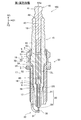
- FIG. 1 is a cross-sectional view of the spark plug 100 of the present embodiment.
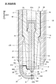
- FIG. 2 is an enlarged cross-sectional view of the vicinity of the tip of the spark plug 100.
- 1 and 2 indicate the axis AXa of the spark plug 100.
- the direction parallel to the axis AXa (vertical direction in FIGS. 1 and 2) is also referred to as an axial direction.
- the radial direction of a circle on a plane perpendicular to the axis AXa with the axis AXa as the center is also simply referred to as "radial direction", and the circumferential direction of the circle is also simply referred to as "circumferential direction".
- FIGS. 1 and 2 are referred to as a front end direction FD, and the upward direction is also referred to as a back end direction BD.
- the lower side in FIGS. 1 and 2 is referred to as the tip end side of the spark plug 100, and the upper side in FIGS. 1 and 2 is referred to as the rear end side of the spark plug 100.
- the spark plug 100 is attached to an internal combustion engine and is used to ignite combustion gases in a combustion chamber of the internal combustion engine.
- the spark plug 100 includes an insulator 10, a center electrode 20, a ground electrode 30, a terminal electrode 40, a metal shell 50, a resistor 70, and conductive seal members 60 and 80.
- the insulator 10 is a substantially cylindrical member having an axial hole 12 which is a through hole extending in the axial direction and penetrating the insulator 10.
- the insulator 10 is formed using, for example, a ceramic such as alumina.
- the insulator 10 includes a collar portion 19, a rear end side body portion 18, a front end side body portion 17, a reduced outer diameter portion 15, and a leg length portion 13.
- the flange portion 19 is a portion of the insulator 10 located substantially at the center in the axial direction.
- the rear end side body portion 18 is located on the rear end side of the collar portion 19 and has an outer diameter smaller than the outer diameter of the collar portion 19.
- the front end side body portion 17 is located on the front end side with respect to the collar portion 19 and has an outer diameter smaller than the outer diameter of the rear end side body portion 18.
- the long leg portion 13 is located on the tip end side of the tip end side body portion 17 and has an outer diameter smaller than the outer diameter of the tip end side body portion 17.
- the outer diameter of the leg portion 13 is reduced toward the tip end, and is exposed to the combustion chamber when the spark plug 100 is attached to an internal combustion engine (not shown).
- the reduced outer diameter portion 15 is a portion which is formed between the leg length portion 13 and the front end side body portion 17 and whose outer diameter is reduced from the rear end side toward the front end side.
- the insulator 10 is located on the tip end side of the large inner diameter portion 12L located on the rear end side and the large inner diameter portion 12L, and the inner diameter is smaller than the large inner diameter portion 12L.
- An inner diameter portion 12S and a reduced diameter inner diameter portion 16 are provided.
- the reduced diameter portion 16 is formed between the large inner diameter portion 12L and the small inner diameter portion 12S, and is a portion whose inner diameter is reduced from the rear end side toward the front end side.
- the position in the axial direction of the reduced diameter portion 16 is the position of the tip end side portion of the tip end side body portion 17 in the present embodiment.
- the metal shell 50 is a cylindrical metal fitting for fixing the spark plug 100 to an engine head (not shown) of an internal combustion engine, which is formed of a conductive metal material (for example, low carbon steel material).
- the metal shell 50 is formed with a through hole 59 penetrating along the axis AXa.
- the metal shell 50 is disposed around the radial direction (that is, the outer periphery) of the insulator 10. That is, the insulator 10 is inserted and held in the through hole 59 of the metal shell 50.
- the tip of the insulator 10 protrudes from the tip of the metal shell 50 toward the tip.
- the rear end of the insulator 10 protrudes from the rear end of the metal shell 50 toward the rear end.
- the metal shell 50 is formed between a tool engagement portion 51 in the form of a hexagonal column engaged with the spark plug wrench, a mounting screw portion 52 for mounting on an internal combustion engine, and the tool engagement portion 51 and the mounting screw portion 52. And a hooked seat portion 54.
- the nominal diameter of the mounting screw portion 52 is, for example, M8 to M14.
- a metal annular gasket 5 is inserted between the mounting screw 52 and the seat 54 of the metal shell 50.
- the gasket 5 seals a gap between the spark plug 100 and the internal combustion engine (engine head) when the spark plug 100 is attached to the internal combustion engine.
- the metal shell 50 further includes a thin caulking portion 53 provided on the rear end side of the tool engagement portion 51, and a thin compression deformation portion 58 provided between the seat portion 54 and the tool engagement portion 51. And have.
- Annular wire packings 6, 7 are arranged in an annular region formed between the inner peripheral surface of a portion from the tool engagement portion 51 to the caulking portion 53 in the metal shell 50 and the outer peripheral surface of the rear end side body portion 18 of the insulator 10.
- Annular wire packings 6, 7 are arranged in an annular region formed between the inner peripheral surface of a portion from the tool engagement portion 51 to the caulking portion 53 in the metal shell 50 and the outer peripheral surface of the rear end side body portion 18 of the insulator 10.
- a powder of talc (talc) 9 is filled between the two line packings 6 and 7 in the area concerned.
- the rear end of the crimped portion 53 is bent inward in the radial direction and fixed to the outer peripheral surface of the insulator 10.
- the compression deformation portion 58 of the metal shell 50 is compressed and deformed when the crimped portion 53 fixed to the outer peripheral surface of the insulator 10 is pressed toward the tip end during manufacturing.
- the insulator 10 is pressed toward the tip side in the metal shell 50 through the wire packings 6, 7 and the talc 9.
- a reduced diameter portion 15 (insulator side step) of the insulator 10 by a step portion 56 (a fitting side step portion) formed on the inner periphery of the metal shell 50 at the mounting screw portion 52 via the annular plate packing 8 Section) is pressed.
- the plate packing 8 prevents the gas in the combustion chamber of the internal combustion engine from leaking from the gap between the metal shell 50 and the insulator 10 to the outside.
- the center electrode 20 includes a rod-shaped center electrode body 21 extending along the axial direction, and a center electrode tip 29.
- the center electrode body 21 is held at a tip end side portion inside the axial hole 12 of the insulator 10. That is, the rear end side (the rear end side of the center electrode body 21) of the center electrode 20 is disposed in the shaft hole 12.
- the center electrode body 21 is formed using a metal having high corrosion resistance and heat resistance, such as nickel (Ni) or an alloy containing Ni as a main component (for example, NCF 600, NCF 601).
- the center electrode body 21 may have a two-layer structure including a base material formed of Ni or a Ni alloy, and a core portion embedded inside the base material.
- the core is made of, for example, copper or an alloy containing copper as a main component, which is more excellent in thermal conductivity than the base material.
- the center electrode body 21 includes a collar 24 provided at a predetermined position in the axial direction, and a head 23 (electrode head) which is a portion on the rear end side of the collar 24. And a leg portion 25 (electrode leg portion) which is a portion on the tip end side of the heel portion 24.
- the flange portion 24 is supported from the distal end side by the reduced diameter portion 16 of the insulator 10. That is, the center electrode body 21 is locked to the reduced diameter portion 16.
- the tip end side of the leg portion 25, that is, the tip end of the center electrode body 21 protrudes from the tip end 10 A of the insulator 10 toward the tip end side.
- the center electrode tip 29 is, for example, a member having a substantially cylindrical shape, and is joined to the end of the center electrode body 21 (the end of the leg 25) using, for example, laser welding.
- the front end surface of the center electrode tip 29 is a first discharge surface 295 that forms a spark gap with the ground electrode tip 39 described later.
- the center electrode tip 29 is formed using, for example, a high melting point noble metal such as iridium (Ir) or platinum (Pt), or an alloy containing the noble metal as a main component.
- the terminal electrode 40 is a rod-like member extending in the axial direction.
- the terminal electrode 40 is inserted into the axial hole 12 of the insulator 10 from the rear end side, and is located on the rear end side of the center electrode 20 in the axial hole 12.
- the terminal electrode 40 is formed of a conductive metal material (for example, low carbon steel), and on the surface of the terminal electrode 40, for example, a plating such as Ni is formed for corrosion protection.
- the terminal electrode 40 has a hook 42 (terminal jaw) formed at a predetermined position in the axial direction, a cap mounting part 41 positioned on the rear end side of the hook 42, and a leg 43 on the tip side of the hook 42. And (terminal legs).
- the cap mounting portion 41 of the terminal electrode 40 is exposed to the rear end side of the insulator 10.
- the leg 43 of the terminal electrode 40 is inserted into the axial hole 12 of the insulator 10.
- a plug cap to which a high voltage cable (not shown) is connected is mounted on the cap mounting portion 41, and a high voltage for generating a discharge is applied.
- the resistor 70 is disposed in the axial hole 12 of the insulator 10 between the front end of the terminal electrode 40 and the rear end of the center electrode 20.
- the resistor 70 has, for example, a resistance value (for example, 5 K ⁇ ) of 1 K ⁇ or more, and has a function of reducing radio wave noise at the time of spark generation.
- the resistor 70 is formed of, for example, a composition including glass particles as main components, ceramic particles other than glass, and a conductive material.
- the gap between the resistor 70 and the center electrode 20 in the shaft hole 12 is filled with the conductive seal member 60.
- the gap between the resistor 70 and the terminal electrode 40 is filled with the seal member 80. That is, the seal member 60 is in contact with the center electrode 20 and the resistor 70 respectively, and the center electrode 20 and the resistor 70 are separated.
- the seal member 80 is in contact with the resistor 70 and the terminal electrode 40, and separates the resistor 70 and the terminal electrode 40 from each other.
- the seal members 60 and 80 electrically and physically connect the center electrode 20 and the terminal electrode 40 via the resistor 70.
- the seal members 60 and 80 are formed of a conductive material, for example, a composition containing glass particles such as B 2 O 3 —SiO 2 and metal particles (Cu, Fe, etc.).
- the ground electrode 30 (ground electrode main body 31) is a rod-like body having a square cross section as shown in FIG.
- the ground electrode body 31 has a connection end 312 and a free end 311 opposite to the connection end 312 as both ends.
- the connection end 312 is joined to the end 50A of the metal shell 50 by, for example, resistance welding.
- the metal shell 50 and the ground electrode body 31 are electrically and physically connected.
- the vicinity of the connection end 312 of the ground electrode body 31 extends in the direction of the axis AXa, and the vicinity of the free end 311 extends in the direction perpendicular to the axis AXa.
- the rod-like ground electrode body 31 is curved by about 90 degrees in the central portion.
- the ground electrode body 31 is formed using a metal having high corrosion resistance and heat resistance, Ni, or an alloy mainly composed of Ni (for example, NCF 600, NCF 601).
- the ground electrode main body 31 includes a base material and a core portion formed of a metal (for example, copper) having a higher thermal conductivity than the base material and embedded in the base material, as the center electrode main body 21. It may have a two-layer structure.
- a ground electrode tip 39 having a second discharge surface 395 opposed to the first discharge surface 295 of the center electrode 20 with a gap G formed therebetween is joined.
- the ground electrode tip 39 has, for example, a cylindrical shape or a square pole shape.
- a gap G between the first discharge surface 295 and the second discharge surface 395 is a so-called spark gap in which a discharge occurs.
- the ground electrode tip 39 is formed using, for example, a noble metal or an alloy containing a noble metal as a main component, similarly to the center electrode tip 29.
- the tip end 10A of the insulator 10 (the tip end of the leg length 13) is located on the tip end side of the tip end 50A of the metal shell 50.
- the distance in the axial direction between the front end 10A of the insulator 10 and the front end 50A of the metal shell 50 is taken as a protrusion amount H.
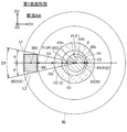
- FIG. 3 is a view showing a cross section AA perpendicular to the axis AXa, passing through a portion of the insulator 10 on the tip end side of the tip end 50A of the metal shell 50. As shown in FIG. In FIG. 2, the cross section AA is indicated by a broken line.
- the cross section AA includes the ground electrode 30 (connection end 312), the center electrode 20 (legs 25), and the insulator 10 (legs 13).
- the metal shell 50 is not included in the cross section AA.
- the broken line in FIG. 3 indicates the position of the metal shell 50 as viewed from the tip end along the axis AXa.
- the shortest distance between the inner circumferential surface 30i of the ground electrode 30 and the outer circumferential surface 10o of the insulator 10 is C3. Since the spark plug 100 is a relatively small diameter spark plug, the shortest distance C3 is 1.2 mm or less.
- the axis (central axis) of the insulator 10 (leg length 13) and the axis of the metal shell 50 are the axis AXa of the spark plug 100.
- the axes of the head portion 23 and the collar portion 24 of the center electrode main body 21 are similarly the axes AXa of the spark plug 100.
- the axis of the leg 25 of the center electrode body 21 and the axis of the center electrode tip 29, that is, the axis on the tip end side of the ridge 24 of the center electrode 20 is an axis AXb different from the axis AXa.
- the axis of the ground electrode tip 39 of the ground electrode 30 is also an axis AXb different from the axis AXa.
- a direction (rightward direction in FIG. 3) from the center 30C of the ground electrode 30 (connection end 312) toward the axis AXa of the spark plug 100 is taken as a first direction D1.
- a direction (upper direction in FIG. 3) perpendicular to the first direction D1 is taken as a second direction D2.
- the axis AXb is in the first direction D1 when viewed from the axis AXa. That is, in the cross section AA, the axis AXb of the center electrode 20 (leg portion 25) is offset in the first direction D1 with respect to the axis AXa of the metallic shell 50 and the insulator 10.
- the distance between the inner circumferential surface 10i of the insulator 10 and the outer circumferential surface 20o of the center electrode 20 differs depending on the position in the circumferential direction viewed from the axis AXb of the center electrode 20.
- the circumferential position at which the distance C between the inner circumferential surface 10i of the insulator 10 and the outer circumferential surface 20o of the center electrode 20 is maximized is taken as a first position P1.
- a circumferential position at which the distance C between the inner circumferential surface 10i of the insulator 10 and the outer circumferential surface 20o of the center electrode 20 is minimum is taken as a second position P2.
- the first position P1 and the second position P2 are different. Then, the distance between the inner circumferential surface 10i of the insulator 10 and the outer circumferential surface 20o of the center electrode 20 at the first position P1 is taken as a first distance C1 (also referred to as the maximum clearance C1). The distance between the inner circumferential surface 10i of the insulator 10 and the outer circumferential surface 20o of the center electrode 20 in the above is the second distance C2 (also referred to as the minimum clearance C2).
- tangents L1 and L2 are taken as tangents L1 and L2. It is a range in the circumferential direction sandwiched by two tangent lines, and a range in which the ground electrode 30 is positioned is taken as a ground electrode range ER.
- the first position P1 is located within the ground electrode range ER. Specifically, the first position is a position in a direction opposite to the first direction D1 when viewed from the axis AXb.
- the second position P2 is located outside the ground electrode range ER. Specifically, the second position P2 is a position directed in the first direction D1 when viewed from the axis AXb.
- Position P ( ⁇ ) in the circumferential direction in cross section AA is a line segment connecting axis AXb and position P ( ⁇ ) in cross section AA, and a line segment connecting axis AX b and reference position P (0) It is expressed by an angle ⁇ between them.
- position P1 of maximum clearance C1 is at position P (180) and position P2 of minimum clearance C2 is at position P (0).
- the ground electrode range ER is a range of an angle (2 ⁇ ⁇ ) centered on the position P (180), that is, a range from the position P (180 ⁇ ) to the position P (180 + ⁇ ). ⁇ is, for example, about 10 degrees.
- the position P (180) is a position in the circumferential direction from the axis line AXb of the center electrode 20 toward the center 30C of the ground electrode 30 in the cross section AA.
- the shortest distance C3 is 1.2 mm or less
- so-called side spark easily occurs as compared with the case where the shortest distance C3 is larger than 1.2 mm.
- the side spark is a defect that discharge occurs between the center electrode 20 and the connection end 312 of the ground electrode 30 or the tip 50A of the metal shell 50 via the surface of the insulator 10.
- the shortest distance C3 is 1.2 mm or less, but the first position P1 described above is located within the ground electrode range ER in the cross section AA of FIG.
- the position P2 is located outside the ground electrode range ER.
- the side spray is on a path from the center electrode 20 to a direction in the ground electrode range ER (for example, in the opposite direction to the first direction D1 in FIG. 2 and FIG. 3) like a side spray passing the path FT shown in FIG. It is easy to occur in Of the entire circumference of the front end 10A of the metal shell 50, the portion to which the connection end 312 of the ground electrode 30 is connected is particularly high in electric field strength. In other words, in the cross section AA, the side spark has different easiness to occur depending on the position in the circumferential direction viewed from the axis line AXb of the center electrode 20. Specifically, at a position within the ground electrode range ER, side sparks are more likely to occur than a position outside the ground electrode range ER.
- the insulator 10 in the ground electrode range ER is The distance between the inner peripheral surface 10i and the outer peripheral surface 20o of the center electrode 20 can be longer than the distance between the inner peripheral surface 10i of the insulator 10 and the outer peripheral surface 20o of the center electrode 20 outside the ground electrode range ER. .
- the insulation resistance between the inner circumferential surface 10i of the insulator 10 and the outer circumferential surface 20o of the center electrode 20 in the ground electrode range ER is set to the inner circumferential surface 10i of the insulator 10 outside the ground electrode range ER and the center electrode 20 It can be larger than the insulation resistance between the outer peripheral surface 20 o of As a result, the occurrence of side spark can be suppressed at a position within the ground electrode range ER where side spark easily occurs. Therefore, even if the shortest distance C3 is 1.2 mm or less, the occurrence of side sparks can be suppressed.
- the distance between the tip end 10A of the insulator 10 and the tip end 50A of the metal shell 50 in the axial direction that is, the protrusion amount H in FIG. Is preferred.
- the electric field strength is locally high.
- side spark easily occurs between the tip 10 A of the metal shell 50 and the center electrode 20.
- the creeping path ST is a path along the surface (for example, the outer peripheral surface 10 o) of the insulator 10 and is, for example, a portion indicated by a broken line in the path FT of FIG. 2.
- the shortest distance C3 between the inner circumferential surface 30i of the ground electrode 30 and the outer circumferential surface 10o of the insulator 10 in the cross section AA of FIG. 3 is preferably 1 mm or less.
- the shortest distance C3 is 1 mm or less at the cross section AA, in particular, side spark easily occurs. According to the above configuration, in the cross section AA, even if the shortest distance C3 is 1 mm or less, the occurrence of side spark can be suppressed.
- the distance C1 between the inner circumferential surface 10i of the insulator 10 and the outer circumferential surface 20o of the center electrode 20 at the first position P1 is a first distance C1.
- the distance C2 between the inner circumferential surface 10i of the insulator 10 and the outer circumferential surface 20o of the center electrode 20 at the second position P2 is a second distance C2
- the first distance C1 is the second distance It is preferable that it is 3 times or more of C2. According to the above configuration, it is possible to sufficiently lengthen the path (e.g., the path FT in FIG. 2) of energization when a side spark occurs in the ground electrode range ER. As a result, the occurrence of side sparks can be further suppressed.
- A-2 First Evaluation Test
- 12 types of samples SA having a shortest distance C3 of 1 mm in FIG. 3 and 12 types of samples SB having a shortest distance C3 of 1.2 mm for the ignition plug A total of 36 types of samples were created, with 12 types of samples SC having a shortest distance C3 of 1.4 mm.
- the shortest distance C3 is adjusted to one of 1.0 mm, 1.2 mm, and 1.4 mm by changing the inner diameter in the vicinity of the end 50A of the metal shell 50.
- the cross section AA of each sample was measured at a position 1.0 mm away from the end 50A of the metal shell 50 on the end side.
- 12 types of samples SA have a circumferential position P1 (first position P1) at which the maximum clearance C1 is located and a circumferential position P2 (second position) at which the minimum clearance C2 is located. It is different.
- the configurations other than the first position P1 and the second position P2 are the same in each sample.
- the first position P1 and the second position P2 of the 12 types of samples SA are shifted by 30 degrees.
- the angles ⁇ indicating the first positions P1 of the 12 types of samples SA are 0, 30, 60, 90, 120, 150, 180, 210, 240, 270, 300, 330, respectively.
- the samples SA, SB, and SC are also expressed as samples SA ( ⁇ ), SB ( ⁇ ), and SC ( ⁇ ) using the angle ⁇ indicating the first position P1 of the 12 types of samples SA.
- the second position P2 is on the opposite side of the first position P1 across the axis AXb.
- samples SA (180), SB (180), SC (180) are the spark plug 100 of the embodiment of FIG. 3, the first position P1 is the position P (180) and the second position P2 is the position P (0).
- the first position P1 is located within the ground electrode range ER, and the second position P2 is located outside the ground electrode range ER.
- the first position P1 is located outside the ground electrode range ER, and the second position P2 is grounded. It is located within the electrode range ER.
- the first position P1 and the second position P1 are both located outside the ground electrode range ER.
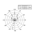
- FIG. 4 is a graph showing the evaluation results of the first evaluation test.
- the circumferential position in the graph of FIG. 4 indicates the first position P1 of each sample (the circumferential position at which the maximum clearance C1 is located).
- the rate of side sparks is plotted on the radial axis of the graph.
- the side spark occurrence rate of the sample SA (180) at the first position P1 at the position P (180) of the ground electrode 30 is the lowest, 4%. Then, the side spark incidence rate of the samples SA (150) and SA (210) whose first position P1 is 30 degrees away from the position P (180) of the ground electrode 30 is as low as that of the sample SA (180) , 5%. In addition, in the samples SA (120) and SA (240) where the first position P1 is 60 degrees away from the position P (180) of the ground electrode 30, the side spark is slightly generated compared to the sample SA (180) The rate was high, 10%.
- the sample SA in which the first position P1 is 90 degrees or more from the position P (180) of the ground electrode 30 is compared with the samples SA (120) and SA (240) 60 degrees from the position P (180).
- the rate of side sparks increased significantly.
- the side spark incidence rate of samples SA (270) and SA (90) was 30% and 25%
- the side spark incidence rate of samples SA (300) and SA (60) was 36%.
- the side spark occurrence rate further increases significantly.
- the side spark incidence rate of samples SA (330) and SA (30) was 60%.
- the side spark occurrence rate is maximum, which is 72%.
- the side spark incidence rate of the sample SB (180) at the first position P1 at the position P (180) of the ground electrode 30 is the lowest and 4%.
- the side spark incidence rate of the samples SB (150) and SB (210) whose first position P1 is 30 degrees away from the position P (180) of the ground electrode 30 is as low as the sample SB (180). , 5%.
- the side spark is slightly generated compared to the sample SB (180). The rate was high, 10%.
- the sample SB in which the first position P1 is 90 degrees or more away from the position P (180) of the ground electrode 30 is compared with the samples SB (120) and SB (240) 60 degrees away from the position P (180).
- the rate of side sparks increased significantly.
- the side spark incidence rate of samples SB (270) and SB (90) was 25%
- the side spark incidence rate of samples SB (300) and SB (60) was 30%.
- the side spark occurrence rate further increases significantly.
- the side spark incidence rate of samples SB (330) and SB (30) was 50%.
- the side spark occurrence rate is maximum, which is 60%.
- the side spark incidence rate of the sample SC (180) at the first position P1 at the position P (180) of the ground electrode 30 is the lowest and 4% . Then, the side spark incidence rate of the samples SC (150) and SC (210) whose first position P1 is 30 degrees away from the position P (180) of the ground electrode 30 is as low as the sample SC (180). , 5%. In addition, in the samples SC (120) and SC (240) in which the first position P1 is 60 degrees away from the position P (180) of the ground electrode 30, the side spark is slightly generated compared to the sample SC (180). The rate was high, 10%.
- the side spark generation rate was similar to that of the samples SC (120) and SC (240). That is, the side spark incidence rate of samples SC (90), SC (60), SC (30), SC (0), SC (270), SC (300), and SC (330) is 10% to 12%. there were.
- the occurrence of side spark can be suppressed significantly.
- the shortest distance C3 was 1.0 mm, it was confirmed that the effect of suppressing the generation of side sparks was high.
- the first distance C1 (0.15 mm) of each sample is set to three times the second distance C2 (0.05 mm).
- the path e.g., the path FT in FIG.
- A-3 Second Evaluation Test
- the projecting amounts H of the nine types of samples are ⁇ 0.2 mm, 0 mm, 0.2 mm, 0.5 mm, 1 mm, 2 mm, 3 mm, 4 mm, and 5 mm, respectively.
- the configurations other than the protrusion amount H of these samples are the same as the sample SB (180) used in the first evaluation test.
- the protrusion amount H of negative value means that the front end 10A of the insulator 10 is positioned on the rear end side relative to the front end 50A of the metal shell 50.
- FIG. 5 is a graph showing the evaluation results of the second evaluation test.
- the evaluation result is plotted with the horizontal axis as the protrusion amount H and the vertical axis as the horizontal axis generation rate.
- the rate of occurrence of side sparks in the samples having a protrusion amount H of 0.5 mm or more was 20% or less. That is, the side spark incidence rates of the samples having the protrusion amount H of 0.5 mm, 1 mm, 2 mm, 3 mm, 4 mm and 5 mm are 5%, 4%, 4%, 10%, 15% and 20%, respectively. there were.
- the side spark incidence rate of the sample whose protrusion amount H is smaller than 0.5 mm was 40% or more.
- the side spark incidence rates of the samples having the protrusion amount H of ⁇ 0.2 mm, 0 mm and 0.2 mm were 40%, 55% and 40%. According to the second evaluation test, it was confirmed that the occurrence of side spray can be further suppressed when the protrusion amount H in FIG. 2 is 0.5 mm or more.
- FIG. 6 is an enlarged cross-sectional view of the vicinity of a tip end of a spark plug according to a second embodiment.
- the spark plug according to the second embodiment includes a center electrode 20B different from the center electrode 20 (FIG. 2) of the spark plug 100 according to the first embodiment.
- the configuration of the portion of the spark plug of the second embodiment excluding the center electrode 20B is the same as the configuration of the spark plug 100 of the first embodiment.
- the configuration of the head portion 23 and the heel portion 24 is the same as that of the center electrode 20 of the first embodiment.
- the configuration of the leg 25B is different from that of the center electrode 20 of the first embodiment.
- the leg 25B of the center electrode 20B includes a first leg 26B on the rear end side and a second leg 27B on the front end side.
- the axis of the first leg 26B is the axis AXa of the spark plug, as is the axis of the head 23 and the collar 24.
- the axis of the second leg 27B is an axis AXb different from the axis AXa.
- the axis AXb is also an axis of the ground electrode tip 39 of the ground electrode 30. Similar to the first embodiment, the axis AXb of the second leg 27B is offset in the first direction D1 with respect to the axis AXa of the metal shell 50 and the insulator 10.
- the position (first position P1) of the maximum clearance C1 is located on the opposite side to the first direction D1 when viewed from the axis AXb of the center electrode 20B. ing. That is, the first position P1 is located on the side where the ground electrode 30 is located (within the ground electrode range ER).
- the position (second position P2) of the minimum clearance C2 is located in the first direction D1 when viewed from the axis AXb of the center electrode 20B. That is, the second position P2 is located outside the ground electrode range ER.
- FIG. 7 is a view showing a cross section AA of a spark plug according to a third embodiment.
- the spark plug of the third embodiment includes a center electrode 20C different from the center electrode 20 (FIG. 2) of the spark plug 100 of the first embodiment.
- the configuration of the portion excluding the center electrode 20C in the spark plug of the third embodiment is the same as the configuration of the spark plug 100 of the first embodiment.
- the cross section AA of FIG. 7 passes through the portion of the insulator 10 closer to the tip end than the tip 50A of the metal shell 50, and Vertical cross section is shown.
- the center electrode 20C includes a leg 25C different from the leg 25 of the center electrode 20 of the first embodiment.
- the other configuration of the center electrode 20C is the same as that of the center electrode 20 of the first embodiment.
- the cross section of the leg 25C in the direction perpendicular to the axis AXa is not a circle.
- the outer circumferential surface 20Co of the leg 25C includes an arc-shaped first portion 21o and a straight second portion 22o.
- the second portion 22o is located on the side of the ground electrode 30 as viewed from the axis AXa
- the first portion 21o is located on the opposite side to the ground electrode 30 (the first direction D1 side) as viewed from the axis AXa. ing.
- the distance from the axis AXa to a point on the second portion 22o is shorter than the distance from the axis AXa to a point on the first portion 21o.
- the position of the maximum clearance C1 (first position P1) is located on the side where the second portion 22o is located. That is, the first position P1 is located on the side where the ground electrode 30 is located (within the ground electrode range ER).
- the position (second position P2) of the minimum clearance C2 is located on the opposite side (outside of the ground electrode range ER) to the ground electrode 30.
- the minimum clearance C2 may be zero. That is, for example, in the first embodiment, the leg portion 25 may be in contact with the inner circumferential surface 10i of the insulator 10 (the leg portion 13) at the second position P2 (P (0)).
- the center electrodes 20, 20B, and 20C in each of the above embodiments may or may not include a tip.
- the ground electrode 30 may or may not include a tip.
- the position of the maximum clearance C1 and the position of the minimum clearance C2 by shifting the axis AXb of the leg 25 of the center electrode 20 with respect to the axis AXa of the spark plug 100; Form.
- the thickness of the insulator 10 thinner at the position on the side of the ground electrode 30 than at the side opposite to the ground electrode 30, the position of the maximum clearance C1 and the position of the minimum clearance C2 , May be formed.
- the configuration of the center electrodes 20, 20B, and 20C has been mainly described, but other elements, for example, materials and dimensions of the metal shell 50, the terminal electrode 40, the ground electrode 30, etc. , Can be changed in various ways.
- the material of the metal shell 50 may be a low carbon steel plated with zinc, nickel or the like, or a low carbon steel not plated with these metals.
- the ground electrode 30 may form a spark gap in the direction perpendicular to the axial direction, facing the tip portion of the center electrode in the direction perpendicular to the axial direction.
- the present invention can be suitably used for a spark plug.
- Body 18 Rear end body 19: collar 19 20, 20B, 20C: center electrode 20B: central electrode 21: central electrode body 23: head 24: collar 24: 25 leg , 25B: leg portion 25C: leg portion 26B: first leg portion 27B: second leg portion 29: central electrode tip 30: ground electrode 31: ground electrode main body 39: ground electrode tip 40: Terminal electrode 41 Cap mounting portion 42 Collar portion 43 Leg portion 50 Main body fitting 51 Tool engagement portion 52 Mounting screw portion 53 Crimping portion 54 Seat portion 56 Stepped part, 58: compression deformation part, 59: through hole, 60: sealing member, 70: resistor, 80: sealing member, 00 ...
- spark plug 311 ... free end, 312 ... connection end, G ... gap, H ... protrusion amount, C ... distance, P1 ... first position, C1 ... maximum clearance, P2 ... second position, C2 ... minimum clearance, C3 ... shortest distance, AA ... cross section, ER ... ground electrode range, AXa ... axis, AXb ... axis
Landscapes
- Spark Plugs (AREA)
Abstract
点火プラグは、筒状の絶縁体と、後端側が軸孔内に配置され、先端側が絶縁体より先端側に突出した中心電極と、絶縁体の外周に配置される主体金具と、主体金具の先端に接続された接続端部と、中心電極との間に間隙を形成して対向する自由端部と、を備える接地電極と、を備える。軸線と垂直で接地電極と絶縁体とが含まれる断面において、中心電極の外周面と絶縁体の内周面との間の距離が最大となる周方向の位置を第1の位置とし、中心電極の外周面と絶縁体の内周面との間の距離が最小となる周方向の位置を第2の位置とし、中心電極の中心から接地電極に対して引かれた2本の接線の間の周方向の範囲を接地電極範囲とするとき、第1の位置は、接地電極範囲内に位置し、第2の位置は、接地電極範囲外に位置し、接地電極の内周面と絶縁体の外周面との間の最短距離は、1mm以下である。
Description
本明細書は、内燃機関等において燃料ガスに点火するための点火プラグに関する。
内燃機関に用いられる点火プラグとして、主体金具に接続された接地電極と、中心電極と、の間に電圧が印加されることによって、中心電極の先端部と接地電極の先端部との間に形成されたギャップに、放電を発生させる。
内燃機関の設計の自由度を確保する観点から、点火プラグの小径化が求められている。点火プラグが小径化するほど、主体金具も小径化するため、中心電極と主体金具との間の径方向の距離を確保することが困難になる。このために、点火プラグが小径化するほど、中心電極と、接地電極と主体金具との接続部の近傍と、の間に、絶縁体の表面を介して、放電が発生する不具合(横飛火とも呼ぶ)が発生しやすくなる。このような放電は、本来のギャップにおける放電とは異なる位置で発生するので、本来の着火性能を発揮できない。
特許文献1には、主体金具の内周面と、絶縁体の外周面と、を同心円からずらして配置することで、横飛火の発生を抑制できる点火プラグが開示されている。
本明細書は、点火プラグにおいて、上述した横飛火の発生を抑制できる新たな技術を開示する。
本明細書に開示される技術は、以下の適用例として実現することが可能である。
[適用例1]軸線方向に延びる軸孔を有する筒状の絶縁体と、
前記軸線方向に延び、後端側が前記軸孔内に配置され、先端側が前記絶縁体より先端側に突出した中心電極と、
前記絶縁体の外周に配置される主体金具と、
前記主体金具の先端に接続された接続端部と、前記接続端部とは反対側で、前記中心電極との間に間隙を形成して対向する自由端部と、を備える接地電極と、
を備える点火プラグであって、
前記絶縁体の先端は、前記主体金具の先端よりも先端側に位置し、
前記軸線と垂直な断面であって、前記接地電極と前記絶縁体とが含まれる断面において、
前記中心電極の外周面と前記絶縁体の内周面との間の距離が最大となる周方向の位置を第1の位置とし、
前記第1の位置とは異なる周方向の位置であり、前記中心電極の外周面と前記絶縁体の内周面との間の距離が最小となる周方向の位置を第2の位置とし、
前記中心電極の中心から前記接地電極に対して引かれた2本の接線の間の周方向の範囲であり、前記接地電極が位置する範囲を、接地電極範囲とするとき、
前記第1の位置は、前記接地電極範囲内に位置し、
前記第2の位置は、前記接地電極範囲外に位置し、
前記接地電極の内周面と前記絶縁体の外周面との間の最短距離は、1mm以下であることを特徴とする、点火プラグ。
上記断面において、接地電極と絶縁体との距離が、1mm以下である場合には、中心電極と、接地電極の接続端部や主体金具の先端と、の間に、絶縁体の表面を介して、放電が発生する不具合(横飛火)が発生しやすくなる。上記構成によれば、上記断面において、中心電極と絶縁体との距離が最大となる第1の位置が、接地電極範囲内に位置し、中心電極と絶縁体との距離が最小となる第2の位置が、接地電極範囲外に位置する。この結果、上記断面において、接地電極と絶縁体との距離が1mm以下であっても、横飛火の発生を抑制することができる。
[適用例2]適用例1に記載の点火プラグであって、
前記絶縁体の先端と、前記主体金具の先端と、の間の前記軸線方向の距離は、0.5mm以上であることを特徴とする、点火プラグ。
前記絶縁体の先端と、前記主体金具の先端と、の間の前記軸線方向の距離は、0.5mm以上であることを特徴とする、点火プラグ。
主体金具の先端は、局所的な電界強度が高いので、主体金具の先端と、中心電極と、の間で、横飛火が発生しやすい。上記構成によれば、主体金具の先端と中心電極との間における絶縁体の沿面経路を十分に長くすることができるので、横飛火の発生をさらに抑制することができる。
[適用例3]適用例1または2に記載の点火プラグであって、
前記断面において、
前記第1の位置における前記絶縁体の内周面と前記中心電極の外周面との間の距離を、第1の距離とし、
前記第2の位置における前記絶縁体の内周面と前記中心電極の外周面との間の距離を、第2の距離とするとき、
前記第1の距離は前記第2の距離の3倍以上であることを特徴とする、点火プラグ。
前記断面において、
前記第1の位置における前記絶縁体の内周面と前記中心電極の外周面との間の距離を、第1の距離とし、
前記第2の位置における前記絶縁体の内周面と前記中心電極の外周面との間の距離を、第2の距離とするとき、
前記第1の距離は前記第2の距離の3倍以上であることを特徴とする、点火プラグ。
上記構成によれば、第1の位置における第1の距離は、第2の位置における第2の距離の3倍以上であるので、接地電極範囲内において横飛火が発生する際の通電の経路を十分に長くすることができる。この結果、横飛火の発生をさらに抑制することができる。
なお、本明細書に開示される技術は、種々の態様で実現することが可能であり、例えば、点火プラグや点火プラグを用いた点火装置、その点火プラグを搭載する内燃機関や、その点火プラグを用いた点火装置を搭載する内燃機関、点火プラグの電極等の態様で実現することができる。
A.実施形態:
A-1.スパークプラグの構成:
図1は本実施形態の点火プラグ100の断面図である。図2は、点火プラグ100の先端近傍の拡大断面図である。図1、図2の一点破線は、点火プラグ100の軸線AXaを示している。軸線AXaと平行な方向(図1、図2の上下方向)を軸線方向とも呼ぶ。軸線AXaを中心とし、軸線AXaと垂直な面上の円の径方向を、単に「径方向」とも呼び、当該円の周方向を、単に「周方向」とも呼ぶ。図1における下方向を先端方向FDと呼び、上方向を後端方向BDとも呼ぶ。図1、図2における下側を、点火プラグ100の先端側と呼び、図1、図2における上側を点火プラグ100の後端側と呼ぶ。
A-1.スパークプラグの構成:
図1は本実施形態の点火プラグ100の断面図である。図2は、点火プラグ100の先端近傍の拡大断面図である。図1、図2の一点破線は、点火プラグ100の軸線AXaを示している。軸線AXaと平行な方向(図1、図2の上下方向)を軸線方向とも呼ぶ。軸線AXaを中心とし、軸線AXaと垂直な面上の円の径方向を、単に「径方向」とも呼び、当該円の周方向を、単に「周方向」とも呼ぶ。図1における下方向を先端方向FDと呼び、上方向を後端方向BDとも呼ぶ。図1、図2における下側を、点火プラグ100の先端側と呼び、図1、図2における上側を点火プラグ100の後端側と呼ぶ。
点火プラグ100は、内燃機関に取り付けられ、内燃機関の燃焼室内の燃焼ガスに着火するために用いられる。点火プラグ100は、絶縁体10と、中心電極20と、接地電極30と、端子電極40と、主体金具50と、抵抗体70と、導電性のシール部材60、80と、を備える。
絶縁体10は、軸線方向に延び、絶縁体10を貫通する貫通孔である軸孔12を有する略円筒状の部材である。絶縁体10は、例えば、アルミナ等のセラミックスを用いて形成されている。絶縁体10は、鍔部19と、後端側胴部18と、先端側胴部17と、縮外径部15と、脚長部13と、を備えている。
鍔部19は、絶縁体10における軸線方向の略中央に位置する部分である。後端側胴部18は、鍔部19より後端側に位置し、鍔部19の外径より小さな外径を有している。先端側胴部17は、鍔部19より先端側に位置し、後端側胴部18の外径より小さな外径を有している。脚長部13は、先端側胴部17より先端側に位置し、先端側胴部17の外径よりも小さな外径を有している。脚長部13の外径は、先端側ほど縮径され、点火プラグ100が内燃機関(図示せず)に取り付けられた際には、その燃焼室に曝される。縮外径部15は、脚長部13と先端側胴部17との間に形成され、後端側から先端側に向かって外径が縮径した部分である。
絶縁体10は、内周側の構成の観点でみると、後端側に位置する大内径部12Lと、大内径部12Lよりも先端側に位置し、大内径部12Lよりも内径が小さな小内径部12Sと、縮内径部16と、を備えている。縮内径部16は、大内径部12Lと小内径部12Sとの間に形成され、後端側から先端側に向かって内径が縮径した部分である。縮内径部16の軸線方向の位置は、本実施形態では、先端側胴部17の先端側の部分の位置である。
主体金具50は、導電性の金属材料(例えば、低炭素鋼材)で形成され、内燃機関のエンジンヘッド(図示省略)に点火プラグ100を固定するための円筒状の金具である。主体金具50には、軸線AXaに沿って貫通する貫通孔59が形成されている。主体金具50は、絶縁体10の径方向の周囲(すなわち、外周)に配置されている。すなわち、主体金具50の貫通孔59内に、絶縁体10が挿入・保持されている。絶縁体10の先端は、主体金具50の先端より先端側に突出している。絶縁体10の後端は、主体金具50の後端より後端側に突出している。
主体金具50は、スパークプラグレンチが係合する六角柱形状の工具係合部51と、内燃機関に取り付けるための取付ネジ部52と、工具係合部51と取付ネジ部52との間に形成された鍔状の座部54と、を備えている。取付ネジ部52の呼び径は、例えば、M8~M14である。
主体金具50の取付ネジ部52と座部54との間には、金属製の環状のガスケット5が嵌挿されている。ガスケット5は、点火プラグ100が内燃機関に取り付けられた際に、点火プラグ100と内燃機関(エンジンヘッド)との隙間を封止する。
主体金具50は、さらに、工具係合部51の後端側に設けられた薄肉の加締部53と、座部54と工具係合部51との間に設けられた薄肉の圧縮変形部58と、を備えている。主体金具50における工具係合部51から加締部53に至る部位の内周面と、絶縁体10の後端側胴部18の外周面と、の間に形成される環状の領域には、環状の線パッキン6、7が配置されている。当該領域における2つの線パッキン6、7の間には、タルク(滑石)9の粉末が充填されている。加締部53の後端は、径方向内側に折り曲げられて、絶縁体10の外周面に固定されている。主体金具50の圧縮変形部58は、製造時において、絶縁体10の外周面に固定された加締部53が先端側に押圧されることにより、圧縮変形する。圧縮変形部58の圧縮変形によって、線パッキン6、7およびタルク9を介し、絶縁体10が主体金具50内で先端側に向け押圧される。環状の板パッキン8を介して、主体金具50の内周で取付ネジ部52の位置に形成された段部56(金具側段部)によって、絶縁体10の縮外径部15(絶縁体側段部)が押圧される。この結果、内燃機関の燃焼室内のガスが、主体金具50と絶縁体10との隙間から外部に漏れることが、板パッキン8によって防止される。
中心電極20は、軸線方向に沿って延びる棒状の中心電極本体21と、中心電極チップ29と、を備えている。中心電極本体21は、絶縁体10の軸孔12の内部の先端側の部分に保持されている。すなわち、中心電極20の後端側(中心電極本体21の後端側)は、軸孔12内に配置されている。中心電極本体21は、耐腐食性と耐熱性が高い金属、例えば、ニッケル(Ni)またはNiを主成分とする合金(例えば、NCF600、NCF601)を用いて形成されている。中心電極本体21は、NiまたはNi合金で形成された母材と、該母材の内部に埋設された芯部と、を含む2層構造を有しても良い。この場合には、芯部は、例えば、母材よりも熱伝導性に優れる銅または銅を主成分とする合金で形成される。
中心電極本体21は、図2に示すように、軸線方向の所定の位置に設けられた鍔部24と、鍔部24よりも後端側の部分である頭部23(電極頭部)と、鍔部24よりも先端側の部分である脚部25(電極脚部)と、を備えている。鍔部24は、絶縁体10の縮内径部16によって、先端側から支持されている。すなわち、中心電極本体21は、縮内径部16に係止されている。脚部25の先端側、すなわち、中心電極本体21の先端は、絶縁体10の先端10Aより先端側に突出している。
中心電極チップ29は、例えば、略円柱形状を有する部材であり、中心電極本体21の先端(脚部25の先端)に、例えば、レーザ溶接を用いて、接合されている。中心電極チップ29の先端面は、後述する接地電極チップ39との間で火花ギャップを形成する第1放電面295である。中心電極チップ29は、例えば、イリジウム(Ir)や白金(Pt)などの高融点の貴金属や、当該貴金属を主成分とする合金が用いて、形成されている。
端子電極40は、軸線方向に延びる棒状の部材である。端子電極40は、絶縁体10の軸孔12に後端側から挿通され、軸孔12内において、中心電極20よりも後端側に位置している。端子電極40は、導電性の金属材料(例えば、低炭素鋼)で形成され、端子電極40の表面には、例えば、防食のために、Niなどのめっきが形成されている。
端子電極40は、軸線方向の所定位置に形成された鍔部42(端子顎部)と、鍔部42より後端側に位置するキャップ装着部41と、鍔部42より先端側の脚部43(端子脚部)と、を備えている。端子電極40のキャップ装着部41は、絶縁体10より後端側に露出している。端子電極40の脚部43は、絶縁体10の軸孔12に挿入されている。キャップ装着部41には、高圧ケーブル(図示外)が接続されたプラグキャップが装着され、放電を発生するための高電圧が印加される。
抵抗体70は、絶縁体10の軸孔12内において、端子電極40の先端と中心電極20の後端との間に、配置されている。抵抗体70は、例えば、1KΩ以上の抵抗値(例えば、5KΩ)を有し、火花発生時の電波ノイズを低減する機能を有する。抵抗体70は、例えば、主成分であるガラス粒子と、ガラス以外のセラミック粒子と、導電性材料と、を含む組成物で形成されている。
軸孔12内における、抵抗体70と中心電極20との隙間は、導電性のシール部材60によって埋められている。抵抗体70と端子電極40との隙間は、シール部材80によって埋められている。すなわち、シール部材60は、中心電極20と抵抗体70とにそれぞれ接触し、中心電極20と抵抗体70とを離間している。シール部材80は、抵抗体70と端子電極40にそれぞれ接触し、抵抗体70と端子電極40とを離間している。このように、シール部材60、80は、中心電極20と端子電極40とを、抵抗体70を介して、電気的、かつ、物理的に、接続している。シール部材60、80は、導電性を有する材料、例えば、例えば、B2O3-SiO2系等のガラス粒子と金属粒子(Cu、Feなど)とを含む組成物で形成されている。
接地電極30(接地電極本体31)は、図2に示すように、断面が四角形の棒状体である。接地電極本体31は、両端部として、接続端部312と、接続端部312の反対側に位置する自由端部311と、を有している。接続端部312は、主体金具50の先端50Aに、例えば、抵抗溶接によって、接合されている。これによって、主体金具50と接地電極本体31とは、電気的および物理的に接続される。接地電極本体31の接続端部312の近傍は、軸線AXaの方向に延びており、自由端部311の近傍は、軸線AXaと垂直な方向に延びている。棒状の接地電極本体31は、中央部分において、約90度だけ湾曲している。
接地電極本体31は、耐腐食性と耐熱性が高い金属、NiまたはNiを主成分とする合金(例えば、NCF600、NCF601)を用いて形成されている。接地電極本体31は、中心電極本体21と同様に、母材と、母材より熱伝導性が高い金属(例えば、銅)を用いて形成され、母材に埋設された芯部と、を含む2層構造を有しても良い。
自由端部311には、中心電極20の第1放電面295との間に間隙Gを形成して対向する第2放電面395を有する接地電極チップ39が接合されている。接地電極チップ39は、例えば、円柱形状や四角柱形状を有している。第1放電面295と第2放電面395との間の間隙Gは、放電が発生するいわゆる火花ギャップである。接地電極チップ39は、中心電極チップ29と同様に、例えば、貴金属、または、貴金属を主成分とする合金を用いて形成される。
ここで、図2に示すように、絶縁体10の先端10A(脚長部13の先端)は、主体金具50の先端50Aよりも先端側に位置している。絶縁体10の先端10Aと、主体金具50の先端50Aと、の間の軸線方向の距離を、突出量Hとする。
図3は、絶縁体10のうち、主体金具50の先端50Aよりも先端側の部分を通り、軸線AXaと垂直な断面AAを示す図である。図2には、断面AAが破線で示されている。
図3に示すように、断面AAには、接地電極30(接続端部312)と、中心電極20(脚部25)と、絶縁体10(脚長部13)と、を含んでいる。断面AAには、主体金具50は含まれない。図3の破線は、軸線AXaに沿って先端側から見た場合の主体金具50の位置を示している。
断面AAにおいて、接地電極30の内周面30iと絶縁体10の外周面10oとの間の最短距離をC3とする。点火プラグ100は、比較的小径のスパークプラグであるので、最短距離C3は、1.2mm以下である。
図2、図3に示すように、絶縁体10(脚長部13)の軸線(中心軸)と、主体金具50の軸線とは、点火プラグ100の軸線AXaである。そして、中心電極20のうち、中心電極本体21の頭部23および鍔部24の軸線は、同様に、点火プラグ100の軸線AXaである。これに対して、中心電極本体21の脚部25および中心電極チップ29の軸線、すなわち、中心電極20のうち、鍔部24よりも先端側の軸線は、軸線AXaとは異なる軸線AXbである。また、接地電極30の接地電極チップ39の軸線も、軸線AXaとは異なる軸線AXbである。
ここで、図3の断面AAにおいて、接地電極30(接続端部312)の中心30Cから、点火プラグ100の軸線AXaに向かう方向(図3の右方向)を第1方向D1とする。断面AAにおいて、第1方向D1と垂直な方向(図3の上方向)を第2方向D2とする。軸線AXbは、軸線AXaから見て第1方向D1にある。すなわち、断面AAにおいて、主体金具50および絶縁体10の軸線AXaに対して、中心電極20(脚部25)の軸線AXbは、第1方向D1にずれている。
このために、断面AAにおいて、絶縁体10の内周面10iと中心電極20の外周面20oとの間の距離は、中心電極20の軸線AXbから見た周方向の位置によって、異なる。ここで、絶縁体10の内周面10iと中心電極20の外周面20oとの間の距離Cが、最大となる周方向の位置を、第1の位置P1とする。また、絶縁体10の内周面10iと中心電極20の外周面20oとの間の距離Cが、最小となる周方向の位置を、第2の位置P2とする。図3から明らかなように、第1の位置P1と第2の位置P2とは異なる。そして、第1の位置P1における絶縁体10の内周面10iと中心電極20の外周面20oとの間の距離を、第1の距離C1(最大クリアランスC1とも呼ぶ)とし、第2の位置P2における絶縁体10の内周面10iと中心電極20の外周面20oとの間の距離を、第2の距離C2(最小クリアランスC2とも呼ぶ)とする。
ここで、断面AAにおいて、中心電極20の軸線AXbから、接地電極30に対して引かれた2本の接線を、接線L1、L2とする。2本の接線に挟まれた周方向の範囲であり、接地電極30が位置する範囲を、接地電極範囲ERとする。
図3に示すように、第1の位置P1は、接地電極範囲ER内に位置している。具体的には、第1の位置は、軸線AXbから見て、第1方向D1とは反対方向の位置である。第2の位置P2は、接地電極範囲ER外に位置している。具体的には、第2の位置P2は、軸線AXbから見て第1方向D1に向かう位置である。
ここで、図3に示すように、断面AAにおいて、断面AAの軸線AXbからみて第1方向D1(図3の右方向)の位置、すなわち、図3の位置P(0)を基準の位置とする(θ=0)。断面AAにおける周方向の位置P(θ)は、断面AAにおいて、軸線AXbと位置P(θ)とを結ぶ線分と、軸線AXbと基準の位置P(0)とを結ぶ線分と、の間の角度θで表される。例えば、図3では、最大クリアランスC1の位置P1は、位置P(180)にあり、最小クリアランスC2の位置P2は、位置P(0)にある。接地電極範囲ERは、位置P(180)を中心とした角度(2×α)の範囲、すなわち、位置P(180-α)から位置P(180+α)の範囲である。αは、例えば、約10度である。位置P(180)は、断面AAにおいて、中心電極20の軸線AXbから接地電極30の中心30Cに向かう周方向の位置である。
ここで、最短距離C3が、1.2mm以下である場合には、最短距離C3が1.2mmより大きい場合と比較して、いわゆる横飛火が発生しやすくなる。横飛火は、中心電極20と、接地電極30の接続端部312や主体金具50の先端50Aと、の間に、絶縁体10の表面を介して、放電が発生する不具合である。
本実施形態での点火プラグ100では、最短距離C3が1.2mm以下であるが、図3の断面AAにおいて、上述した第1の位置P1は、接地電極範囲ER内に位置し、第2の位置P2は、接地電極範囲ER外に位置している。この結果、最短距離C3が1.2mm以下であっても、横飛火の発生を抑制することができる。
より詳しく説明する。横飛火は、図2に示す経路FTを通る横飛火のように、中心電極20から接地電極範囲ER内の方向(例えば、図2、図3の第1方向D1の反対方向)に向かう経路上で発生しやすい。主体金具50の先端10Aの全周のうちでも、接地電極30の接続端部312が接続されている部分は、特に、電界強度が高いためである。換言すれば、横飛火は、断面AAにおいて、中心電極20の軸線AXbから見た周方向の位置によって、発生しやすさが異なる。具体的には、接地電極範囲ER内の位置では、接地電極範囲ER外の位置よりも横飛火が発生しやすい。
本実施形態では、第1の位置P1は、接地電極範囲ER内に位置し、第2の位置P2は、接地電極範囲ER外に位置しているから、接地電極範囲ER内における絶縁体10の内周面10iと中心電極20の外周面20oとの間の距離を、接地電極範囲ER外における絶縁体10の内周面10iと中心電極20の外周面20oとの間の距離よりも長くできる。したがって、接地電極範囲ER内における絶縁体10の内周面10iと中心電極20の外周面20oとの間の絶縁抵抗を、接地電極範囲ER外における絶縁体10の内周面10iと中心電極20の外周面20oとの間の絶縁抵抗よりも大きくできる。この結果、横飛火が発生しやすい接地電極範囲ER内の位置において、横飛火の発生を抑制できる。従って、最短距離C3が1.2mm以下であっても、横飛火の発生を抑制することができる。
さらに、本実施形態では、絶縁体10の先端10Aと、主体金具50の先端50Aと、の間の軸線方向の間の距離、すなわち、図2の突出量Hは、0.5mm以上であることが好ましい。軸線方向の位置としては、主体金具50の先端50Aでは、局所的に電界強度が高い。このために、図2に示す経路FTのように、主体金具50の先端10Aと、中心電極20と、の間で、横飛火が発生しやすい。上記構成によれば、主体金具50の先端50Aと中心電極20との間における沿面経路STを十分に長くすることができるので、横飛火の発生をさらに抑制することができる。沿面経路STは、絶縁体10の表面(例えば、外周面10o)に沿う経路であり、例えば、図2の経路FTのうち、破線で示す部分である。
さらに、本実施形態では、図3の断面AAにおいて、接地電極30の内周面30iと絶縁体10の外周面10oとの間の最短距離C3は、1mm以下であることが好ましい。断面AAにおいて、最短距離C3が、1mm以下である場合には、特に、横飛火が発生しやすくなる。上記構成によれば、上記断面AAにおいて、最短距離C3が1mm以下であっても、横飛火の発生を抑制することができる。
さらに、本実施形態では、図3の断面AAにおいて、第1の位置P1における絶縁体10の内周面10iと中心電極20の外周面20oとの間の距離C1を、第1の距離C1とし、第2の位置P2における絶縁体10の内周面10iと中心電極20の外周面20oとの間の距離C2を、第2の距離C2とするとき、第1の距離C1は第2の距離C2の3倍以上であることが好ましい。上記構成によれば、接地電極範囲ER内において横飛火が発生する際の通電の経路(例えば、図2の経路FT)を十分に長くすることができる。この結果、横飛火の発生をさらに抑制することができる。
A-2:第1評価試験
第1評価試験では、点火プラグについて、図3の最短距離C3が1mmである12種類のサンプルSAと、最短距離C3が1.2mmである12種類のサンプルSBと、最短距離C3が1.4mmである12種類のサンプルSCと、の合計36種類のサンプルを作成した。なお、最短距離C3は、主体金具50の先端50A近傍の内径を変更することで、1.0mm、1.2mm、1.4mmのいずれかに調整されている。
第1評価試験では、点火プラグについて、図3の最短距離C3が1mmである12種類のサンプルSAと、最短距離C3が1.2mmである12種類のサンプルSBと、最短距離C3が1.4mmである12種類のサンプルSCと、の合計36種類のサンプルを作成した。なお、最短距離C3は、主体金具50の先端50A近傍の内径を変更することで、1.0mm、1.2mm、1.4mmのいずれかに調整されている。
各サンプルに共通な寸法は、以下の通りである。
突出量H:1.5mm
断面AAにおける絶縁体10の外径:φ2.8mm
断面AAにおける絶縁体10の内径:φ1.8mm
断面AAにおける中心電極20の外径:φ1.6mm
断面AAにおける最大クリアランスC1:0.15mm
断面AAにおける最小クリアランスC2:0.05mm
接地電極範囲ERの範囲の幅(2×α):40度
間隙G(火花ギャップ) :0.7mm
突出量H:1.5mm
断面AAにおける絶縁体10の外径:φ2.8mm
断面AAにおける絶縁体10の内径:φ1.8mm
断面AAにおける中心電極20の外径:φ1.6mm
断面AAにおける最大クリアランスC1:0.15mm
断面AAにおける最小クリアランスC2:0.05mm
接地電極範囲ERの範囲の幅(2×α):40度
間隙G(火花ギャップ) :0.7mm
なお、各サンプルの寸法は、断面AAは、主体金具50の先端50Aから先端側に、1.0mm離れた位置の断面にて測定された。
ここで、12種類のサンプルSAは、最大クリアランスC1が位置する周方向の位置P1(第1の位置P1)、および、最小クリアランスC2が位置する周方向の位置P2(第2の位置)がそれぞれ異なる。第1の位置P1、および、第2の位置P2以外の構成は、各サンプルにおいて同一である。
具体的には、12種類のサンプルSAの第1の位置P1および第2の位置P2は、30度ずつずれている。12種類のサンプルSAの第1の位置P1を示す角度θは、それぞれ、0、30、60、90、120、150、180、210、240、270、300、330である。12種類のサンプルSBおよび12種類のサンプルSCについても同様である。12種類のサンプルSAの第1の位置P1を示す角度θを用いて、各サンプルSA、SB、SCを、サンプルSA(θ)、SB(θ)、SC(θ)とも表す。なお、全てのサンプルにおいて、第2の位置P2は、第1の位置P1に対して、軸線AXbを挟んだ反対側にある。
例えば、サンプルSA(180)、SB(180)、SC(180)は、図3の実施形態の点火プラグ100であり、第1の位置P1は、位置P(180)であり、第2の位置P2は、位置P(0)である。サンプルSA(180)、SB(180)、SC(180)では、第1の位置P1は、接地電極範囲ER内に位置しており、第2の位置P2は、接地電極範囲ER外に位置している。これに対して、サンプルSA(0)、SB(0)、SC(0)のサンプルでは、第1の位置P1は、接地電極範囲ER外に位置しており、第2の位置P2は、接地電極範囲ER内に位置している。そして、これら6個のサンプルSA(180)、SB(180)、SC(180)、サンプルSA(0)、SB(0)、SC(0)以外のサンプルでは、第1の位置P1および第2の位置P2は、ともに、接地電極範囲ER外に位置している。
第1評価試験では、各サンプルについて、1秒間に20回の火花放電を発生させる放電試験を、間隙Gが初期値の0.7mmから0.9mmまで摩耗するまで実行した。その後、各サンプルについて、カメラで間隙Gの部分を撮影しながら、さらに、100回の放電を行った。そして、カメラでの撮影結果に基づいて、100回の放電のうち、横飛火が発生した割合を、横飛火発生率(単位は%)としてカウントした。
図4は、第1評価試験の評価結果を示すグラフである。図4のグラフの周方向の位置は、各サンプルの第1の位置P1(最大クリアランスC1が位置する周方向の位置)を示す。グラフの径方向の軸に、横飛火発生率がプロットされている。
最短距離C3が1mmであるサンプルSAでは、第1の位置P1が、接地電極30の位置P(180)にあるサンプルSA(180)の横飛火発生率が最も低く、4%であった。そして、第1の位置P1が、接地電極30の位置P(180)から30度離れたサンプルSA(150)、SA(210)の横飛火発生率は、サンプルSA(180)と同程度に低く、5%であった。また、第1の位置P1が、接地電極30の位置P(180)から60度離れたサンプルSA(120)、SA(240)では、サンプルSA(180)と比較して、若干、横飛火発生率が高く、10%であった。
第1の位置P1が、接地電極30の位置P(180)から90度以上離れたサンプルSAでは、位置P(180)から60度離れたサンプルSA(120)、SA(240)と比較して、大幅に横飛火発生率が高くなった。例えば、サンプルSA(270)、SA(90)の横飛火発生率は、30%、25%であり、サンプルSA(300)、SA(60)の横飛火発生率は、36%であった。
さらに、第1の位置P1が、接地電極30の位置P(180)から150度離れたサンプルでは、さらに、大幅に横飛火発生率が高くなった。例えば、サンプルSA(330)、SA(30)の横飛火発生率は、60%であった。そして、第1の位置P1が、接地電極30の位置P(180)から最も離れたサンプルSA(0)では、横飛火発生率は、最大となり、72%であった。
最短距離C3が1.2mmであるサンプルSBでは、第1の位置P1が、接地電極30の位置P(180)にあるサンプルSB(180)の横飛火発生率が最も低く、4%であった。そして、第1の位置P1が、接地電極30の位置P(180)から30度離れたサンプルSB(150)、SB(210)の横飛火発生率は、サンプルSB(180)と同程度に低く、5%であった。また、第1の位置P1が、接地電極30の位置P(180)から60度離れたサンプルSB(120)、SB(240)では、サンプルSB(180)と比較して、若干、横飛火発生率が高く、10%であった。
第1の位置P1が、接地電極30の位置P(180)から90度以上離れたサンプルSBでは、位置P(180)から60度離れたサンプルSB(120)、SB(240)と比較して、大幅に横飛火発生率が高くなった。例えば、サンプルSB(270)、SB(90)の横飛火発生率は、25%であり、サンプルSB(300)、SB(60)の横飛火発生率は、30%であった。
さらに、第1の位置P1が、接地電極30の位置P(180)から150度離れたサンプルでは、さらに、大幅に横飛火発生率が高くなった。例えば、サンプルSB(330)、SB(30)の横飛火発生率は、50%であった。そして、第1の位置P1が、接地電極30の位置P(180)から最も離れたサンプルSB(0)では、横飛火発生率は、最大となり、60%であった。
最短距離C3が1.4mmであるサンプルSCでは、第1の位置P1が、接地電極30の位置P(180)にあるサンプルSC(180)の横飛火発生率が最も低く、4%であった。そして、第1の位置P1が、接地電極30の位置P(180)から30度離れたサンプルSC(150)、SC(210)の横飛火発生率は、サンプルSC(180)と同程度に低く、5%であった。また、第1の位置P1が、接地電極30の位置P(180)から60度離れたサンプルSC(120)、SC(240)では、サンプルSC(180)と比較して、若干、横飛火発生率が高く、10%であった。
第1の位置P1が、接地電極30の位置P(180)から90度以上離れたサンプルSCでは、サンプルSC(120)、SC(240)と同程度の横飛火発生率であった。すなわち、サンプルSC(90)、SC(60)、SC(30)、SC(0)、SC(270)、SC(300)、SC(330)の横飛火発生率は、10%~12%であった。
以上の結果から、最短距離C3が1.2mm以下である場合には、第1の位置P1を、接地電極範囲ER内(例えば、θ=180度の位置)に配置することで、第1の位置P1を、接地電極範囲ER外(例えば、θ=90~270度の位置)に配置する場合と比較して、大幅に横飛火の発生を抑制できることが確認できた。特に、最短距離C3が1.0mmである場合には、横飛火の発生を抑制できる効果が高いことが確認できた。
また、最短距離C3が1.4mmである場合には、第1の位置P1を、接地電極範囲ER内(例えば、θ=180度の位置)に配置することで、第1の位置P1を、接地電極範囲ER外(例えば、θ=90~270度の位置)に配置する場合と比較して、僅かに横飛火の発生を抑制できるが、抑制できる程度は、僅かであることが確認できた。これは、最短距離C3が1.4mmである場合には、第1の位置P1が、接地電極範囲ER外に配置されても、あまり横飛火が発生しないためである。
また、上述のとおり、各サンプルの第1の距離C1(0.15mm)は、第2の距離C2(0.05mm)の3倍に設定されている。このように、本評価試験によって、第1の距離C1が第2の距離C2の3倍である場合には、第1の位置P1を、接地電極範囲ER内(例えば、θ=180度の位置)に配置することで、第1の位置P1を、接地電極範囲ER外(例えば、θ=90~270度の位置)に配置する場合と比較して、大幅に横飛火の発生を抑制できることが確認できた。これは、第1の距離C1が第2の距離C2の3倍であると、接地電極範囲ER内において横飛火が発生する際の通電の経路(例えば、図2の経路FT)が十分に長くなるからである。このために、第1の距離C1が第2の距離C2の3倍以上である場合には、大幅に横飛火の発生を抑制できると考えられる。
A-3:第2評価試験
第2評価試験では、突出量Hがそれぞれ異なる9種類のサンプルが準備された。9種類のサンプルの突出量Hは、それぞれ、-0.2mm、0mm、0.2mm、0.5mm、1mm、2mm、3mm、4mm、5mmである。これらのサンプルの突出量H以外の構成は、第1評価試験で用いたサンプルSB(180)と同じである。負の値の突出量Hは、絶縁体10の先端10Aが、主体金具50の先端50Aよりも後端側に位置することを意味する。
第2評価試験では、突出量Hがそれぞれ異なる9種類のサンプルが準備された。9種類のサンプルの突出量Hは、それぞれ、-0.2mm、0mm、0.2mm、0.5mm、1mm、2mm、3mm、4mm、5mmである。これらのサンプルの突出量H以外の構成は、第1評価試験で用いたサンプルSB(180)と同じである。負の値の突出量Hは、絶縁体10の先端10Aが、主体金具50の先端50Aよりも後端側に位置することを意味する。
第2評価試験では、第1評価試験と同様に、各サンプルについて、1秒間に20回の火花放電を発生させる放電試験を、間隙Gが初期値の0.7mmから0.9mmまで摩耗するまで実行した。その後、各サンプルについて、さらに、100回の放電を行い、100回の放電のうち、横飛火が発生した割合を、横飛火発生率(単位は%)としてカウントした。
図5は、第2評価試験の評価結果を示すグラフである。図5のグラフでは、横軸を突出量Hとし、縦軸を横軸発生率として、評価結果がプロットされている。突出量Hが、0.5mm以上のサンプルの横飛火発生率は、20%以下であった。すなわち、突出量Hが、0.5mm、1mm、2mm、3mm、4mm、5mmであるサンプルの横飛火発生率は、それぞれ、5%、4%、4%、10%、15%、20%であった。これに対して、突出量Hが、0.5mmより小さなサンプルの横飛火発生率は、40%以上であった。具体的には、突出量Hが、-0.2mm、0mm、0.2mmであるサンプルの横飛火発生率は、40%、55%、40%であった。第2評価試験によって、図2の突出量Hは、0.5mm以上である場合には、より横飛火の発生を抑制できることが確認できた。
B.第2実施形態
図6は、第2実施形態の点火プラグの先端近傍の拡大断面図である。第2実施形態の点火プラグは、第1実施形態の点火プラグ100の中心電極20(図2)とは異なる中心電極20Bを備えている。第2実施形態の点火プラグのうち、中心電極20Bを除いた部分の構成は、第1実施形態の点火プラグ100の構成と同一である。
図6は、第2実施形態の点火プラグの先端近傍の拡大断面図である。第2実施形態の点火プラグは、第1実施形態の点火プラグ100の中心電極20(図2)とは異なる中心電極20Bを備えている。第2実施形態の点火プラグのうち、中心電極20Bを除いた部分の構成は、第1実施形態の点火プラグ100の構成と同一である。
中心電極20Bのうち、頭部23と鍔部24との構成は、第1実施形態の中心電極20と同一である。第2実施形態では、中心電極20Bのうち、脚部25Bの構成が、第1実施形態の中心電極20とは異なる。
中心電極20Bの脚部25Bは、後端側の第1脚部26Bと、先端側の第2脚部27Bと、を備えている。第1脚部26Bの軸線は、頭部23および鍔部24の軸線と同様に、点火プラグの軸線AXaである。これに対して、第2脚部27Bの軸線は、軸線AXaとは異なる軸線AXbである。軸線AXbは、接地電極30の接地電極チップ39の軸線でもある。第1実施形態と同様に、主体金具50および絶縁体10の軸線AXaに対して、第2脚部27Bの軸線AXbは、第1方向D1にずれている。このために、第1実施形態と同様に、断面AAにおいて、最大クリアランスC1の位置(第1の位置P1)は、中心電極20Bの軸線AXbから見て第1方向D1とは反対側に位置している。すなわち、第1の位置P1は、接地電極30が位置する側(接地電極範囲ER内)に位置する。そして、最小クリアランスC2の位置(第2の位置P2)は、中心電極20Bの軸線AXbから見て第1方向D1に位置する。すなわち、第2の位置P2は、接地電極範囲ER外に位置する。この結果、第2実施形態の点火プラグも、第1実施形態の点火プラグ100と同様に、横飛火を抑制することができる。
C.第3実施形態
図7は、第3実施形態の点火プラグの断面AAを示す図である。第3実施形態の点火プラグは、第1実施形態の点火プラグ100の中心電極20(図2)とは異なる中心電極20Cを備えている。第3実施形態の点火プラグのうち、中心電極20Cを除いた部分の構成は、第1実施形態の点火プラグ100の構成と同一である。図7の断面AAは、第1実施形態の点火プラグ100の断面AA(図3)と同様に、絶縁体10のうち、主体金具50の先端50Aよりも先端側の部分を通り、軸線AXaと垂直な断面を示す。
図7は、第3実施形態の点火プラグの断面AAを示す図である。第3実施形態の点火プラグは、第1実施形態の点火プラグ100の中心電極20(図2)とは異なる中心電極20Cを備えている。第3実施形態の点火プラグのうち、中心電極20Cを除いた部分の構成は、第1実施形態の点火プラグ100の構成と同一である。図7の断面AAは、第1実施形態の点火プラグ100の断面AA(図3)と同様に、絶縁体10のうち、主体金具50の先端50Aよりも先端側の部分を通り、軸線AXaと垂直な断面を示す。
中心電極20Cは、第1実施形態の中心電極20の脚部25とは異なる脚部25Cを備える。中心電極20Cのその他の構成は、第1実施形態の中心電極20と同一である。図7に示すように、脚部25Cの軸線AXaと垂直な方向の断面は、円ではない。断面AAにおいて、脚部25Cの外周面20Coは、円弧状の第1部分21oと、直線状の第2部分22oと、を含んでいる。軸線AXaから見て接地電極30側には、第2部分22oが位置しており、軸線AXaから見て接地電極30とは反対側(第1方向D1側)は、第1部分21oが位置している。軸線AXaから第2部分22o上の点までの距離は、軸線AXaから第1部分21o上の点までの距離よりも短い。このために、最大クリアランスC1の位置(第1の位置P1)は、第2部分22oが位置する側に位置する。すなわち、第1の位置P1は、接地電極30が位置する側(接地電極範囲ER内)に位置する。そして、最小クリアランスC2の位置(第2の位置P2)は、接地電極30とは反対側(接地電極範囲ER外)に位置している。この結果、第3実施形態の点火プラグも、第1実施形態の点火プラグ100と同様に、横飛火を抑制することができる。
D.変形例:
(1)上記各実施形態において、最小クリアランスC2は、0であっても良い。すなわち、例えば、第1実施形態において、脚部25は、第2の位置P2(P(0))において、絶縁体10(脚長部13)の内周面10iと接触していても良い。
(1)上記各実施形態において、最小クリアランスC2は、0であっても良い。すなわち、例えば、第1実施形態において、脚部25は、第2の位置P2(P(0))において、絶縁体10(脚長部13)の内周面10iと接触していても良い。
(2)上記各実施形態の中心電極20、20B、20Cは、チップを備えていても良いし、チップを備えていなくても良い。同様に、接地電極30は、チップを備えていても良いし、チップを備えていなくても良い。
(3)上記第1実施形態において、中心電極20の脚部25の軸線AXbを、点火プラグ100の軸線AXaに対してずらずことによって、最大クリアランスC1の位置と、最小クリアランスC2の位置と、を形成している。これに代えて、絶縁体10の厚さを、接地電極30側の位置において、接地電極30とは反対側の位置よりも薄くすることによって、最大クリアランスC1の位置と、最小クリアランスC2の位置と、を形成しても良い。
(4)上記各実施形態において、中心電極20、20B、20Cの構成を中心に説明してきたが、他の要素、例えば、主体金具50、端子電極40、接地電極30などの材質や寸法などは、様々に変更可能である。例えば、主体金具50の材質は、亜鉛やニッケルなどでめっきされた低炭素鋼でも良いし、これらのめっきがなされていない低炭素鋼でも良い。また、また、接地電極30は、中心電極の先端部分と軸線方向と垂直な方向に対向して、軸線方向と垂直な方向の火花ギャップを形成しても良い。
以上、実施形態、変形例に基づき本発明について説明してきたが、上記した発明の実施の形態は、本発明の理解を容易にするためのものであり、本発明を限定するものではない。本発明は、その趣旨並びに特許請求の範囲を逸脱することなく、変更、改良され得ると共に、本発明にはその等価物が含まれる。
本発明は、点火プラグに好適に利用できる。
5…ガスケット、6…線パッキン、8…板パッキン、9…タルク、10…絶縁体、12…軸孔、13…脚長部、15…縮外径部、16…縮内径部、17…先端側胴部、18…後端側胴部、19…鍔部、20、20B、20C…中心電極、20B…中心電極、21…中心電極本体、23…頭部、24…鍔部、25…脚部、25B…脚部、25C…脚部、26B…第1脚部、27B…第2脚部、29…中心電極チップ、30…接地電極、31…接地電極本体、39…接地電極チップ、40…端子電極、41…キャップ装着部、42…鍔部、43…脚部、50…主体金具、51…工具係合部、52…取付ネジ部、53…加締部、54…座部、56…段部、58…圧縮変形部、59…貫通孔、60…シール部材、70…抵抗体、80…シール部材、100…点火プラグ、311…自由端部、312…接続端部、G…間隙、H…突出量、C…距離、P1…第1の位置、C1…最大クリアランス、P2…第2の位置、C2…最小クリアランス、C3…最短距離、AA…断面、ER…接地電極範囲、AXa…軸線、AXb…軸線
Claims (3)
- 軸線方向に延びる軸孔を有する筒状の絶縁体と、
前記軸線方向に延び、後端側が前記軸孔内に配置され、先端側が前記絶縁体より先端側に突出した中心電極と、
前記絶縁体の外周に配置される主体金具と、
前記主体金具の先端に接続された接続端部と、前記接続端部とは反対側で、前記中心電極との間に間隙を形成して対向する自由端部と、を備える接地電極と、
を備える点火プラグであって、
前記絶縁体の先端は、前記主体金具の先端よりも先端側に位置し、
前記軸線と垂直な断面であって、前記接地電極と前記絶縁体とが含まれる断面において、
前記中心電極の外周面と前記絶縁体の内周面との間の距離が最大となる周方向の位置を第1の位置とし、
前記第1の位置とは異なる周方向の位置であり、前記中心電極の外周面と前記絶縁体の内周面との間の距離が最小となる周方向の位置を第2の位置とし、
前記中心電極の中心から前記接地電極に対して引かれた2本の接線の間の周方向の範囲であり、前記接地電極が位置する範囲を、接地電極範囲とするとき、
前記第1の位置は、前記接地電極範囲内に位置し、
前記第2の位置は、前記接地電極範囲外に位置し、
前記接地電極の内周面と前記絶縁体の外周面との間の最短距離は、1mm以下であることを特徴とする、点火プラグ。 - 請求項1に記載の点火プラグであって、
前記絶縁体の先端と、前記主体金具の先端と、の間の前記軸線方向の距離は、0.5mm以上であることを特徴とする、点火プラグ。 - 請求項1または2に記載の点火プラグであって、
前記断面において、
前記第1の位置における前記絶縁体の内周面と前記中心電極の外周面との間の距離を、
第1の距離とし、
前記第2の位置における前記絶縁体の内周面と前記中心電極の外周面との間の距離を、
第2の距離とするとき、
前記第1の距離は前記第2の距離の3倍以上であることを特徴とする、点火プラグ。
Priority Applications (1)
| Application Number | Priority Date | Filing Date | Title |
|---|---|---|---|
| JP2018562269A JPWO2019069640A1 (ja) | 2017-10-06 | 2018-09-11 | 点火プラグ |
Applications Claiming Priority (2)
| Application Number | Priority Date | Filing Date | Title |
|---|---|---|---|
| JP2017-196257 | 2017-10-06 | ||
| JP2017196257 | 2017-10-06 |
Publications (1)
| Publication Number | Publication Date |
|---|---|
| WO2019069640A1 true WO2019069640A1 (ja) | 2019-04-11 |
Family
ID=65994555
Family Applications (1)
| Application Number | Title | Priority Date | Filing Date |
|---|---|---|---|
| PCT/JP2018/033608 Ceased WO2019069640A1 (ja) | 2017-10-06 | 2018-09-11 | 点火プラグ |
Country Status (2)
| Country | Link |
|---|---|
| JP (1) | JPWO2019069640A1 (ja) |
| WO (1) | WO2019069640A1 (ja) |
Citations (4)
| Publication number | Priority date | Publication date | Assignee | Title |
|---|---|---|---|---|
| JPS60140391U (ja) * | 1984-02-27 | 1985-09-17 | トヨタ自動車株式会社 | 点火プラグ |
| JP2010062160A (ja) * | 2007-09-13 | 2010-03-18 | Ngk Spark Plug Co Ltd | スパークプラグ |
| JP2011034959A (ja) * | 2009-07-06 | 2011-02-17 | Ngk Spark Plug Co Ltd | スパークプラグ |
| JP2013055022A (ja) * | 2011-09-06 | 2013-03-21 | Ngk Spark Plug Co Ltd | スパークプラグ |
-
2018
- 2018-09-11 JP JP2018562269A patent/JPWO2019069640A1/ja active Pending
- 2018-09-11 WO PCT/JP2018/033608 patent/WO2019069640A1/ja not_active Ceased
Patent Citations (4)
| Publication number | Priority date | Publication date | Assignee | Title |
|---|---|---|---|---|
| JPS60140391U (ja) * | 1984-02-27 | 1985-09-17 | トヨタ自動車株式会社 | 点火プラグ |
| JP2010062160A (ja) * | 2007-09-13 | 2010-03-18 | Ngk Spark Plug Co Ltd | スパークプラグ |
| JP2011034959A (ja) * | 2009-07-06 | 2011-02-17 | Ngk Spark Plug Co Ltd | スパークプラグ |
| JP2013055022A (ja) * | 2011-09-06 | 2013-03-21 | Ngk Spark Plug Co Ltd | スパークプラグ |
Also Published As
| Publication number | Publication date |
|---|---|
| JPWO2019069640A1 (ja) | 2019-11-14 |
Similar Documents
| Publication | Publication Date | Title |
|---|---|---|
| JP7198907B2 (ja) | スパークプラグ | |
| JP7216802B2 (ja) | スパークプラグ | |
| US8115371B2 (en) | Spark plug | |
| JP2009541946A (ja) | 極細ワイヤ接地電極を備える火花プラグ | |
| JP2014067651A (ja) | スパークプラグ | |
| JP5090898B2 (ja) | スパークプラグ | |
| JP4680792B2 (ja) | スパークプラグ | |
| CN110676694A (zh) | 火花塞 | |
| JP6626473B2 (ja) | 点火プラグ | |
| JP4965422B2 (ja) | スパークプラグ | |
| JP7060551B2 (ja) | スパークプラグ | |
| JP7227933B2 (ja) | スパークプラグ | |
| JPWO2019069640A1 (ja) | 点火プラグ | |
| US10340666B2 (en) | Spark plug | |
| JP6436942B2 (ja) | 点火プラグ | |
| JP7039519B2 (ja) | 点火プラグ | |
| JP6411433B2 (ja) | スパークプラグ | |
| JP6661245B2 (ja) | 点火プラグ | |
| JP6739482B2 (ja) | 点火プラグ | |
| JP7060550B2 (ja) | スパークプラグ | |
| JP2019003722A (ja) | 点火プラグ | |
| JP6559193B2 (ja) | 点火プラグ | |
| JP6559855B2 (ja) | スパークプラグ | |
| JPH07106050A (ja) | スパークプラグ | |
| JP2022045383A (ja) | スパークプラグ |
Legal Events
| Date | Code | Title | Description |
|---|---|---|---|
| ENP | Entry into the national phase |
Ref document number: 2018562269 Country of ref document: JP Kind code of ref document: A |
|
| 121 | Ep: the epo has been informed by wipo that ep was designated in this application |
Ref document number: 18864915 Country of ref document: EP Kind code of ref document: A1 |
|
| NENP | Non-entry into the national phase |
Ref country code: DE |
|
| 122 | Ep: pct application non-entry in european phase |
Ref document number: 18864915 Country of ref document: EP Kind code of ref document: A1 |