WO2019065449A1 - モータ - Google Patents
モータ Download PDFInfo
- Publication number
- WO2019065449A1 WO2019065449A1 PCT/JP2018/034807 JP2018034807W WO2019065449A1 WO 2019065449 A1 WO2019065449 A1 WO 2019065449A1 JP 2018034807 W JP2018034807 W JP 2018034807W WO 2019065449 A1 WO2019065449 A1 WO 2019065449A1
- Authority
- WO
- WIPO (PCT)
- Prior art keywords
- bus bar
- wide
- narrow
- axial direction
- portions
- Prior art date
- Legal status (The legal status is an assumption and is not a legal conclusion. Google has not performed a legal analysis and makes no representation as to the accuracy of the status listed.)
- Ceased
Links
Images




Classifications
-
- H—ELECTRICITY
- H02—GENERATION; CONVERSION OR DISTRIBUTION OF ELECTRIC POWER
- H02K—DYNAMO-ELECTRIC MACHINES
- H02K3/00—Details of windings
- H02K3/46—Fastening of windings on the stator or rotor structure
- H02K3/50—Fastening of winding heads, equalising connectors, or connections thereto
-
- H—ELECTRICITY
- H02—GENERATION; CONVERSION OR DISTRIBUTION OF ELECTRIC POWER
- H02K—DYNAMO-ELECTRIC MACHINES
- H02K3/00—Details of windings
- H02K3/46—Fastening of windings on the stator or rotor structure
- H02K3/52—Fastening salient pole windings or connections thereto
Definitions
- the present invention relates to a motor.
- Patent Document 1 describes a rotating electrical machine for an internal combustion engine provided with such a bus bar.
- the bus bar as described above has a relatively large axial dimension. Therefore, for example, when adopting a configuration in which one bus bar is straddled by another bus bar, the dimension in the axial direction becomes large at the intersection of the bus bars, and there is a problem that the rotary electric machine becomes large in the axial direction.
- One aspect of the motor of the present invention includes a rotor having a shaft disposed along a central axis, a plurality of coils, and a stator radially opposed to the rotor with a gap therebetween, and extending from the coils And a plurality of bus bars electrically connected to the conductive wires.
- the bus bar is a plate whose plate surface is in the axial direction and extends along a plane orthogonal to the axial direction, and the plurality of bus bars include a first bus bar and a second bus bar, and the first bus bar is A first wide width portion, and a first narrow width portion connected to the first wide width portion in a direction in which the first bus bar extends, and having a smaller axial dimension than the first wide width portion;
- the end on one side in the axial direction in the narrow portion is disposed on the other side in the axial direction than the end on the one side in the axial direction in the first wide portion, and the first narrow portion is more axial than the second bus bar
- the motor which is disposed opposite to the other side with a gap on the other side.
- a motor which has a plurality of plate-like bus bars whose plate surfaces extend in the axial direction and which can be miniaturized in the axial direction.
- FIG. 1 is a cross-sectional view showing the motor of the first embodiment.
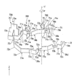
- FIG. 2 is a perspective view showing a plurality of bus bars of the first embodiment.
- FIG. 3 is a perspective view showing the bus bar of the first embodiment.
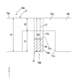
- FIG. 4 is a view of a part of the bus bar of the first embodiment viewed in the direction orthogonal to the plate surface.
- FIG. 5 is a view of a part of the bus bar of the modified example in the first embodiment, viewed in the direction orthogonal to the plate surface.
- FIG. 6 is a view of a part of the bus bar of the second embodiment viewed in the direction orthogonal to the plate surface.
- the Z-axis direction appropriately shown in each drawing is a vertical direction with the positive side as the upper side and the negative side as the lower side.
- a central axis J appropriately shown in each drawing is an imaginary line which is parallel to the Z-axis direction and extends in the vertical direction.
- the axial direction of the central axis J that is, the direction parallel to the vertical direction
- the radial direction centering on the central axis J is simply referred to as “radial direction”.
- the circumferential direction centered on is simply referred to as "circumferential direction”.
- the circumferential direction is appropriately indicated by an arrow ⁇ .
- the positive side in the Z-axis direction in the axial direction is called “upper side”
- the negative side in the Z-axis direction in the axial direction is called “lower side”.
- the lower side corresponds to one side in the axial direction
- the upper side corresponds to the other side in the axial direction.
- the side that proceeds clockwise as viewed from the upper side in the circumferential direction from the upper side to the lower side that is, the side that proceeds in the direction opposite to the direction of the arrow ⁇ will be referred to as “one side in the circumferential direction”.
- the side advancing in the counterclockwise direction as viewed from the upper side to the lower side in the circumferential direction that is, the side advancing in the direction of the arrow ⁇ is referred to as “the other side in the circumferential direction”.
- the vertical direction, the upper side, and the lower side are simply names for describing the relative positional relationship of each part, and the actual positional relationship may be a positional relationship other than the positional relationship indicated by these names. .
- the motor 10 includes a housing 11, a rotor 20, bearings 51 and 52, a stator 30, a bearing holder 40, a bus bar unit 90, and a control device 80. .
- the housing 11 accommodates each part of the motor 10.
- the housing 11 is cylindrical around the central axis J.
- the housing 11 holds the bearing 51 at the bottom on the lower side.
- the rotor 20 has a shaft 21, a rotor core 22, and a magnet 23.
- the shaft 21 is disposed along the central axis J.
- the shaft 21 is rotatably supported by bearings 51 and 52.
- the rotor core 22 has an annular shape fixed to the outer peripheral surface of the shaft 21.
- the magnet 23 is fixed to the outer peripheral surface of the rotor core 22.
- the bearing 51 rotatably supports the shaft 21 on the lower side of the rotor core 22.
- the bearing 52 rotatably supports the shaft 21 on the upper side of the rotor core 22.
- the bearings 51 and 52 are ball bearings.
- the stator 30 faces the rotor 20 in the radial direction via a gap.
- the stator 30 surrounds the rotor 20 at the radially outer side of the rotor 20.
- the stator 30 has a stator core 31, an insulator 34, and a plurality of coils 35.
- the stator core 31 has a core back 32 and a plurality of teeth 33.
- the plurality of coils 35 are respectively attached to the plurality of teeth 33 via the insulators 34.
- the coil 35 is configured by winding a conducting wire around the teeth 33 through the insulator 34.
- a coil lead wire 36 is drawn upward from each coil 35.
- the coil lead wire 36 is a conducting wire extending from the coil 35 and is an end of the conducting wire that constitutes the coil 35.
- the bearing holder 40 is disposed on the upper side of the stator 30.
- the bearing holder 40 has an annular shape centered on the central axis J.
- the bearing holder 40 holds the bearing 52.
- the bearing holder 40 is made of metal.
- the bearing holder 40 has a holder hole 40 a which penetrates the bearing holder 40 in the axial direction.
- the coil lead wire 36 is passed through the holder hole 40a.
- the bus bar unit 90 is disposed on the upper side of the bearing holder 40.
- the bus bar unit 90 has a bus bar holder 60 and a bus bar 70. That is, motor 10 includes bus bar holder 60 and a plurality of bus bars 70.
- the bus bar holder 60 has an annular shape centering on the central axis J.
- the bus bar holder 60 is fixed to the upper surface of the bearing holder 40.
- the bus bar holder 60 is made of resin.
- the bus bar 70 is held by the bus bar holder 60.
- the bus bar 70 is supported by the bus bar holder 60 from the lower side.
- the bus bar 70 is a plate whose plate surface is in the axial direction.
- the thickness of the bus bar 70 is, for example, uniform.
- the bus bar 70 extends along a plane orthogonal to the axial direction.
- the plurality of bus bars 70 are arranged at equal intervals along the circumferential direction. In the present embodiment, the plurality of bus bars 70 have the same shape.
- the plurality of bus bars 70 include bus bars 70A, 70B, and 70C as three bus bars 70, for example. In the following description, the bus bars 70A, 70B, and 70C are simply referred to as the bus bars 70 unless otherwise specified.
- the bus bar 70 has a first member 71, a second member 72, and a power supply connection portion 73.
- the first member 71, the second member 72, and the power supply connection portion 73 are separate members. By connecting the first member 71, the second member 72, and the power supply connection portion 73, one bus bar 70 is formed.
- the first member 71 and the second member 72 are fixed to both sides in the circumferential direction of the power supply connection portion 73, respectively.
- the first member 71, the second member 72, and the power supply connection portion 73 are fixed, for example, by welding.
- a plurality of coil lead wires 36 are connected to the first member 71 and the second member 72, respectively.
- the bus bar 70 is electrically connected to the coil lead wire 36.
- the first coil lead-out wire 36 a and the second coil lead-out wire 36 b of the coil lead-out wires 36 are connected to the first member 71.
- the first coil lead-out wire 36 c and the second coil lead-out wire 36 d of the coil lead-out wires 36 are connected to the second member 72.
- the first coil lead wires 36a and 36c correspond to first conductive wires.
- the second coil leads 36b and 36d correspond to a second conductive wire.
- the first member 71 and the second member 72 have a plate shape whose plate surface is in the axial direction.
- the first member 71 extends in the form of a broken line from the power supply connection portion 73 in the circumferential direction as viewed in the axial direction.
- the second member 72 extends in the form of a broken line from the power supply connection portion 73 to the other side in the circumferential direction as viewed along the axial direction.
- the first member 71 has a plurality of bent portions 71 c bent in a direction orthogonal to the axial direction. The bending directions of the adjacent bending portions 71c in the direction in which the first member 71 extends are opposite to each other.
- the first member 71 extends in a zigzag manner as viewed in the axial direction.
- the second member 72 has a plurality of bends 72c. That is, the bus bar 70 has bent portions 71c and 72c.
- the second member 72 extends in a zigzag manner as viewed in the axial direction.
- proximal side the side connected to the power supply connection portion 73
- distal side the opposite side to the proximal side
- the first member 71 has three first wide portions 74a, 74b, 74c and two first narrow portions 75a, 75b.
- the first narrow portions 75a and 75b are connected to the first wide portions 74a, 74b and 74c in the direction in which the bus bar 70 extends.
- the first narrow width portions 75a and 75b have smaller axial dimensions than the first wide portions 74a, 74b and 74c.
- the axial dimensions of the first wide portions 74a, 74b, 74c are the same.
- the axial dimensions of the first narrow portions 75a and 75b are the same.
- the first wide portions 74a, 74b, 74c are arranged at the same position in the axial direction.
- the first narrow portions 75a and 75b are disposed at the same position in the axial direction.
- the three first wide portions 74a, 74b, 74c and the two first narrow portions 75a, 75b are alternately arranged along the direction in which the first member 71 extends.
- the proximal end of the first wide portion 74 a is connected to the power supply connection portion 73.
- the proximal end of the first wide portion 74 a is the proximal end of the first member 71.
- the first wide portion 74a has two bent portions 71c.
- the first wide portion 74a has a first coil connection portion 76a. That is, the bus bar 70 has the first coil connection portion 76 a.
- the first coil connection portion 76a is connected to the first coil lead wire 36a.
- the first coil connection portion 76a and the first coil lead wire 36a are fixed, for example, by welding.
- the first coil connection portion 76a is a portion between the two bent portions 71c in the first wide portion 74a.
- the first coil connection portion 76a has a rectangular plate shape. That is, the first coil connection portion 76a has a plate shape extending from the bending portion 71c. Therefore, the first coil connection portion 76a can be easily manufactured by bending the plate member. Further, it is easy to secure a space for welding the first coil lead wire 36a to the first coil connection portion 76a.
- the first wide portion 74 a includes a portion of the bus bar 70 between the power supply connection portion 73 and the first coil connection portion 76 a.
- the first narrow width portion 75a is connected to the end on the tip end side of the first wide portion 74a. More specifically, the first narrow width portion 75a is connected to the upper portion of the end portion on the tip end side of the first wide portion 74a. The upper end of the first narrow portion 75a is disposed at the same position in the axial direction as the upper end of the first wide portion 74a. The first narrow width portion 75a linearly extends in a direction parallel to the end on the tip side of the first wide portion 74a. The lower end of the first narrow portion 75a is disposed above the lower end of the first wide portions 74a and 74b.
- the first wide portion 74 b is connected to the end on the tip side of the first narrow portion 75 a. More specifically, the upper portion of the proximal end of the first wide portion 74b is connected to the distal end of the first narrow portion 75a. Thus, the first wide portions 74a and 74b are respectively provided on both sides of the first narrow portion 75a in the direction in which the bus bar 70 extends.
- the first wide portion 74 b has three bent portions 71 c. The proximal end of the first wide portion 74b extends in a direction parallel to the direction in which the first narrow portion 75a extends.
- the first narrow width portion 75 b is connected to the end on the tip side of the first wide portion 74 b. More specifically, the first narrow width portion 75b is connected to the upper portion of the end on the tip side of the first wide portion 74b. The first narrow width portion 75b linearly extends in a direction parallel to the end on the tip end side of the first wide portion 74b. The lower end of the first narrow portion 75b is disposed above the lower end of the first wide portions 74b and 74c.
- the first wide portion 74c is connected to the end on the tip side of the first narrow portion 75b. More specifically, the upper portion of the proximal end of the first wide portion 74c is connected to the distal end of the first narrow portion 75b. Thus, the first wide portions 74 b and 74 c are provided on both sides of the first narrow portion 75 b in the direction in which the bus bar 70 extends.
- the first wide portion 74c has one bent portion 71c. The proximal end of the first wide portion 74c extends in a direction parallel to the direction in which the first narrow portion 75a extends.
- the first wide portion 74c has a second coil connection portion 76b. That is, the bus bar 70 has the second coil connection portion 76b.
- the second coil connection portion 76 b is connected to a second coil lead-out wire 36 b different from the first coil lead-out wire 36 a of the coil lead-out wire 36.
- the second coil connection portion 76 b and the second coil lead wire 36 b are fixed by welding, for example.
- the second coil connection portion 76b is a portion between the bent portion 71c of the first wide portion 74c and the end on the tip side.
- the second coil connection portion 76b has a rectangular plate shape. That is, the second coil connection portion 76b has a plate shape extending from the bending portion 71c. Therefore, the second coil connection portion 76 b can be easily manufactured by bending the plate member. In addition, it is easy to secure a space for welding the second coil lead-out wire 36b to the second coil connection portion 76b.
- the end on the tip end side of the second coil connection portion 76 b is the end on the tip end side of the first wide portion 74 c and is the end on the tip end side of the first member 71.
- the second coil connection portion 76b is disposed closer to the tip than the first coil connection portion 76a. That is, the first coil connection portion 76 a is provided between the power supply connection portion 73 and the second coil connection portion 76 b in the bus bar 70.
- Each of the first narrow portions 75a and 75b is disposed above the first wide portions 74a, 74b and 74c. That is, in the present embodiment, all of the plurality of first narrow portions 75a and 75b are disposed on the same side in the axial direction with respect to the first wide portions 74a, 74b and 74c. Therefore, for example, when the plurality of first narrow portions 75a and 75b are manufactured by punching out a part of the bus bar 70, the plurality of first narrow portions 75a and 75b can be easily manufactured.
- the first narrow portions 75a and 75b are provided in the bus bar 70 between the first coil connection portion 76a and the second coil connection portion 76b.
- the first recessed portion 71a recessed in the axial direction is configured by the first narrow width portion 75a and the two first wide portions 74a and 74b provided on both sides of the first narrow width portion 75a.
- a first recessed portion 71b recessed in the axial direction is configured by the first narrow width portion 75b and the two first wide portions 74b and 74c provided on both sides of the first narrow width portion 75b. That is, the bus bar 70 has the first concave portions 71a and 71b.
- the first recesses 71 a and 71 b are recessed upward from the lower end of the bus bar 70.
- the shape of the inner portion of the first recess 71a is a polygonal shape as viewed in the direction perpendicular to the plate surface of the bus bar 70 in the first narrow width portion 75a.
- the shape of the inner portion of the first recess 71a is a rectangular shape elongated in the direction in which the first narrow portion 75a extends, viewed along the direction orthogonal to the plate surface of the bus bar 70 in the first narrow portion 75a. It is.
- the shape of the first recess 71 b is the same as the shape of the first recess 71 a.
- the second member 72 is disposed at the same position as the first member 71 in the axial direction.
- the second member 72 has three second wide portions 77a, 77b, 77c and two second narrow portions 78a, 78b.
- the second narrow portions 78a and 78b are connected to the second wide portions 77a, 77b and 77c in the direction in which the bus bar 70 extends.
- the second narrow width portions 78a and 78b have smaller axial dimensions than the second wide width portions 77a, 77b and 77c.
- the dimensions in the axial direction of the respective second wide portions 77a, 77b, 77c are the same.
- the axial dimensions of the second narrow portions 78a and 78b are the same.
- the second wide portions 77a, 77b, 77c are arranged at the same position in the axial direction.
- the second narrow portions 78a and 78b are disposed at the same position in the axial direction.
- the three second wide portions 77a, 77b, 77c and the two second narrow portions 78a, 78b are alternately arranged along the direction in which the second member 72 extends.
- the proximal end side of the second wide portion 77 a is connected to the power supply connection portion 73.
- the proximal end of the second wide portion 77 a is the proximal end of the second member 72.
- the second wide portion 77a has four bent portions 72c.
- the second wide portion 77a has a first coil connection portion 79a.
- the first coil connection portion 79a is a portion between two bent portions 72c of the bent portions 72c of the first wide portion 74a.
- the first coil connection portion 79a has the same shape as the first coil connection portion 76a.
- the first coil connection portion 79a is connected to the first coil lead-out wire 36c.
- the second wide portion 77 a includes a portion of the bus bar 70 between the power supply connection portion 73 and the first coil connection portion 79 a.
- the second narrow width portion 78a is connected to the end on the tip side of the second wide portion 77a.
- the 2nd narrow part 78a is connected with the lower part among the end by the side of the tip of the 2nd wide part 77a.
- the lower end of the second narrow portion 78a is disposed at the same position in the axial direction as the lower end of the second wide portion 77a.
- the second narrow portion 78a has one bent portion 72c.
- the second narrow width portion 78a is easy to bend because the axial dimension is relatively small. Therefore, the bent portion 72c can be easily manufactured.
- the upper end of the second narrow portion 78a is disposed lower than the upper end of the second wide portions 77a and 77b.
- the second wide portion 77 b is connected to the end on the tip side of the second narrow portion 78 a. More specifically, the lower portion of the proximal end of the second wide portion 77b is connected to the distal end of the second narrow portion 78a.
- the second wide portions 77a and 77b are provided on both sides of the second narrow portion 78a in the direction in which the bus bar 70 extends.
- the second wide portion 77 b has one bending portion 72 c.
- the proximal end of the second wide portion 77 b extends in a direction parallel to the direction in which the distal end of the second narrow portion 78 a extends.
- the second narrow portion 78b is connected to the end on the tip side of the second wide portion 77b.
- the 2nd narrow part 78b is connected with the lower part among the end by the side of the tip of the 2nd wide part 77b.
- the second narrow portion 78b has one bent portion 72c.
- the second narrow width portion 78 b is easily bent because the axial dimension is relatively small. Therefore, the bent portion 72c can be easily manufactured.
- the upper end of the second narrow portion 78b is disposed lower than the upper ends of the second wide portions 77b and 77c.
- the second wide portion 77c is connected to the end on the tip side of the second narrow portion 78b. More specifically, the lower portion of the proximal end of the second wide portion 77c is connected to the distal end of the second narrow portion 78b.
- the second wide portions 77 b and 77 c are provided on both sides of the second narrow portion 78 b in the direction in which the bus bar 70 extends.
- the second wide portion 77c has one bent portion 72c.
- the proximal end of the second wide portion 77 c extends in a direction parallel to the direction in which the distal end of the second narrow portion 78 a extends.
- the second wide portion 77c has a second coil connection portion 79b.
- the second coil connection portion 79b is a portion of the second wide portion 77c from the bent portion 72c to the end on the tip side.
- the second coil connection portion 79b has the same shape as the second coil connection portion 76b.
- the second coil connection portion 79b is connected to the second coil lead wire 36d.
- the end on the tip end side of the second coil connection portion 79 b is the end on the tip end side of the second wide portion 77 c and is the end on the tip end side of the second member 72.
- the second coil connection portion 79b is disposed closer to the tip than the first coil connection portion 79a. That is, the first coil connection portion 79 a is provided between the power supply connection portion 73 and the second coil connection portion 79 b in the bus bar 70.
- Each of the second narrow portions 78a and 78b is disposed below the second wide portions 77a, 77b and 77c. That is, in the present embodiment, all of the plurality of second narrow portions 78a and 78b are disposed on the same side in the axial direction with respect to the second wide portions 77a, 77b and 77c. Therefore, for example, when the plurality of second narrow portions 78a and 78b are manufactured by punching out a part of the bus bar 70, the plurality of second narrow portions 78a and 78b can be easily manufactured.
- the second narrow width portions 78a and 78b are provided in the bus bar 70 between the first coil connection portion 79a and the second coil connection portion 79b.
- a second recessed portion 72a that is recessed in the axial direction is configured by the second narrow width portion 78a and the two second wide portions 77a and 77b provided on both sides of the second narrow width portion 78a.
- a second recessed portion 72b that is recessed in the axial direction is configured by the second narrow width portion 78b and the two second wide portions 77b and 77c provided on both sides of the second narrow width portion 78b. That is, the bus bar 70 has the second recesses 72a and 72b.
- the second recesses 72 a and 72 b are recessed downward from the upper end of the bus bar 70.
- the shape of the inner portion of the second concave portion 72a is a polygonal shape when viewed along the direction in which the bent portion 72c of the second narrow portion 78a is convex.
- the shape of the inner portion of the second recess 72a is a rectangular shape elongated in the direction in which the second narrow portion 78a extends, as viewed along the direction in which the bent portion 72c in the second narrow portion 78a becomes convex. is there.
- the shape of the second recess 72b is the same as the shape of the second recess 72a.
- the axial dimension H2 of the first narrow portions 75a, 75b is less than half the axial dimension H1 of the first wide portions 74a, 74b, 74c.
- the axial dimension H4 of the second narrow portions 78a and 78b is less than half the axial dimension H3 of the second wide portions 77a, 77b and 77c.
- the axial dimension H1 of the first wide portions 74a, 74b, 74c and the axial dimension H3 of the second wide portions 77a, 77b, 77c are the same.
- the axial dimension H2 of the first narrow width portions 75a and 75b and the axial dimension H4 of the second narrow width portions 78a and 78b are the same.
- An axial distance L1 from the lower end of the first narrow width portion 75a to the lower end of the first wide width portions 74a and 74b is larger than the axial dimension H2 of the first narrow width portion 75a. .
- the sum of the distance L1 and the dimension H2 is equal to the axial dimension H1 of the first wide portions 74a and 74b.
- the axial distance L2 from the upper end of the second narrow width portion 78a to the upper end of the second wide width portions 77a and 77b is larger than the axial dimension H4 of the second narrow width portion 78a.
- the sum of the distance L2 and the dimension H4 is equal to the axial dimension H3 of the second wide portions 77a and 77b.
- the power supply connection portion 73 includes a terminal portion 73 a and a fixing portion 73 b.
- the terminal portion 73 a extends upward and is connected to the control device 80.
- the power supply connection unit 73 is connected to the control device 80.
- the fixing portion 73b is connected to the lower end of the terminal portion 73a.
- the fixing portion 73 b has a plate shape extending in the axial direction.
- the first wide portion 74 a and the second wide portion 77 a are fixed to the fixing portion 73 b.
- the fixing portion 73b is sandwiched from both sides in the circumferential direction by the first wide portion 74a and the second wide portion 77a.
- the bus bars 70 cross each other.
- the first members 71 of one bus bar 70 straddle the upper sides of the second members 72 of the other two bus bars 70 and intersect with the two second members 72.
- the second members 72 of one bus bar 70 straddle the first members 71 of the other two bus bars 70 on the upper side and intersect the two first members 71.
- the bus bar 70A corresponds to the first bus bar
- the bus bars 70B and 70C are the second bus bar It corresponds to
- the first member 71 of the bus bar 70A straddles the upper side of the second member 72 of the bus bar 70B and the upper side of the second member 72 of the bus bar 70C.
- a portion of the first member 71 of the bus bar 70A that straddles the upper side of the second member 72 of the bus bar 70B is a first narrow width portion 75a.
- the first narrow width portion 75a of the bus bar 70A is disposed on the upper side of the second narrow width portion 78a of the bus bar 70B with a gap therebetween.
- the first narrow-width portion 75a of the bus bar 70A, which is the first bus bar is disposed to face the upper side of the bus bar 70B, which is the second bus bar, via a gap.
- the first width is obtained even if the bus bar 70A approaches the bus bar 70B from the upper side until the lower ends of the first wide portions 74a and 74b are lower than the upper end of the second member 72 in the bus bar 70B. It can suppress that narrow portion 75a contacts bus bar 70B. Thereby, a part of bus bar 70A and a part of bus bar 70B can be overlapped and arranged in the direction orthogonal to the axial direction. Therefore, even if the bus bar 70A and the bus bar 70B are overlapped in the axial direction and intersected with each other, it is possible to suppress an increase in the axial dimension at the intersection of the bus bars 70 with each other. Thereby, according to the present embodiment, the motor 10 having a structure in which the plate surface includes the plurality of plate-like bus bars 70 along the axial direction and can be miniaturized in the axial direction can be obtained.
- overlapping of certain objects in a certain direction includes overlapping of certain objects when viewed along a certain direction. That is, overlapping of the bus bars 70 in the direction orthogonal to the axial direction includes that the bus bars 70 overlap when viewed along the direction orthogonal to the axial direction.
- the first wide portions 74 a and 74 b of the bus bar 70 A are positioned below the upper end of the bus bar 70 B, that is, the upper end of the second member 72.
- the upper end portions of the first wide portions 74a and 74b in the bus bar 70A and the upper end portions of the second wide portions 77a and 77b in the bus bar 70B are arranged at the same position in the axial direction. Therefore, the portion excluding the upper end of the first wide portions 74a and 74b of the bus bar 70A is a portion positioned lower than the upper end of the second member 72, and the upper end of the bus bar 70B It is a portion located below the side.
- the first wide portions 74a and 74b are provided on both sides of the first narrow portion 75a, whereby the first recess 71a is provided. Therefore, by locally reducing the axial dimension of the portion of the bus bar 70A intersecting the bus bar 70B, the bus bar 70A and the bus bar 70B overlap in a direction orthogonal to the axial direction. The upper side can be straddled. As a result, it is possible to reduce the portion in which the axial dimension is reduced in the bus bar 70A, and to suppress the reduction in the strength of the bus bar 70A.
- the shape of the inner portion of the first recess 71a is a polygonal shape as viewed in the direction orthogonal to the plate surface of the first narrow portion 75a. Therefore, for example, when producing the first concave portion 71a by punching by press processing, it is easy to punch a part of the bus bar 70A along the inner edge of the first concave portion 71a. Thereby, it is easy to produce the 1st crevice 71a.
- the first wide portions 74a and 74b and the first narrow portion 75a can be produced by producing the first concave portion 71a. Therefore, the fabrication of the first wide portions 74a and 74b and the fabrication of the first narrow portion 75a can be facilitated.
- the bus bar 70B which is the second bus bar includes the second narrow portion 78a.
- the second narrow width portion 78a is disposed to face the lower side of the first narrow width portion 75a of the bus bar 70A, which is the first bus bar, with a gap therebetween. Therefore, the bus bar 70A and the bus bar 70B can be arranged closer to each other in the axial direction. As a result, the axial dimension at the intersection of the bus bars 70 can be further reduced, and the motor 10 can be further miniaturized.
- the second wide portions 77a and 77b are provided on both sides of the second narrow portion 78a, whereby the second recess 72a is provided. Therefore, by locally reducing the axial dimension of the portion of the bus bar 70B intersecting the bus bar 70A, the bus bar 70B and the bus bar 70B overlap in the direction orthogonal to the axial direction, and the upper side of the bus bar 70B is 70A can be straddled. As a result, it is possible to reduce the portion in which the axial dimension is reduced in the bus bar 70B, and to suppress the reduction in the strength of the bus bar 70B.
- the two bus bars 70A and 70B can be made to intersect by engaging the first concave portion 71a and the second concave portion 72a in each of the bus bars 70A and 70B. Therefore, the first concave portion 71a and the second concave portion 72a can be used as marks when arranging the bus bars 70 in combination, and the arrangement of the plurality of bus bars 70 can be performed accurately and easily.
- the inner portion of the first recess 71a in the bus bar 70A and the inner portion of the second recess 72a in the bus bar 70B partially overlap each other.
- the inner portion of the first recess 71b in the bus bar 70A and the inner portion of the second recess 72b in the bus bar 70C partially overlap each other.
- an axial distance L1 from the lower end of the first narrow width portion 75a of the bus bar 70A to the lower side of the first wide portions 74a and 74b is the second width of the bus bar 70B. It is larger than the axial dimension H4 of the narrow portion 78a. Therefore, the whole of the second narrow width portion 78a in the axial direction can be accommodated in a recess formed by the first narrow width portion 75a being recessed upward with respect to the first wide width portions 74a and 74b. This makes it easier to reduce the axial dimension at the intersection of the bus bars 70 with each other. Therefore, the motor 10 can be further miniaturized.
- the axial dimension H2 of the first narrow width portion 75a is less than half the axial dimension H1 of the first wide portions 74a and 74b.
- the axial dimension H4 of the second narrow width portion 78a is less than half of the axial dimension H3 of the second wide portions 77a and 77b.
- the axial dimension H1 of the first wide portions 74a and 74b and the axial dimension H3 of the second wide portions 77a and 77b are the same.
- the bus bar 70A and the bus bar 70B in a state where the end portions on both sides in the axial direction of the first wide portions 74a and 74b and the end portions on both sides in the axial direction of the second wide portions 77a and 77b are aligned. Even if the first and second narrow portions 75a and 78a are provided in the axial direction, a gap is provided between the first narrow portion 75a and the second narrow portion 78a, and the first narrow portion 75a does not contact the second narrow portion 78a.
- the axial dimension of the intersection of the two bus bars 70A and 70B superimposed in the axial direction is the axial dimension of the first wide portions 74a and 74b and the second wide portions 77a and 77b of one bus bar 70.
- a portion straddling the upper side of the second member 72 of the bus bar 70C is a first narrow width portion 75b.
- the first narrow width portion 75b of the bus bar 70A is disposed on the upper side of the second narrow width portion 78b of the bus bar 70C with a gap therebetween.
- the first narrow-width portion 75b of the bus bar 70A which is the first bus bar, is disposed to face the upper side of the bus bar 70C, which is the second bus bar, with a gap therebetween.
- an increase in axial dimension at the intersection of the bus bars 70 can be suppressed.
- the bus bar 70A includes the plurality of first narrow portions 75a and 75b. Therefore, the bus bar 70A can be disposed in a state in which the plurality of bus bars 70 straddle the bus bar 70A.
- the degree of freedom in arrangement of the bus bars 70 can be improved while suppressing increase in axial dimension at the intersections of the bus bars 70 with each other. Therefore, even if three or more bus bars 70 are provided, it is easy to miniaturize motor 10 in the axial direction.
- bus bars 70B and 70C have a plurality of second narrow portions 78a and 78b. Therefore, the plurality of bus bars 70 can be straddled over the bus bars 70B and 70C. Thus, the freedom of arrangement of the bus bars 70 can be further improved while suppressing increase in axial dimension at the intersections between the bus bars 70. Therefore, even when three or more bus bars 70 are provided, the motor 10 can be easily miniaturized in the axial direction.
- the second member 72 is straddled over the other two bus bars 70 while the other two bus bars 70 are straddled by the first member 71.
- the dimensions in the axial direction at the intersections of the bus bars 70 can be made the same as the dimensions in the axial direction of one bus bar 70 while three bus bars 70A, 70B, 70C are superimposed in the axial direction. Therefore, when arranging the three bus bars 70A, 70B, 70C, it is possible to realize a preferable arrangement which can miniaturize the motor 10 in the axial direction.
- the first wide portions 74a, 74b, 74c of the bus bar 70A are arranged at positions different from the bus bar 70B as viewed in the axial direction. Further, the second wide portions 77a, 77b, 77c of the bus bars 70B, 70C are arranged at positions different from the bus bar 70A as viewed in the axial direction. Therefore, the portion where the bus bars 70 intersect with each other can be only the narrow portions. Thus, the axial dimension at the intersection of the bus bars 70 can be suppressed from becoming large.
- the bus bar 70B corresponds to a first bus bar
- the bus bars 70A and 70C It corresponds to 2 bus bars.
- the bus bar 70C corresponds to a first bus bar
- the bus bars 70A and 70B are a second bus bar It corresponds to
- control device 80 is disposed on the upper side of bus bar unit 90. Control device 80 is electrically connected to bus bar 70 via terminal portion 73a. Control device 80 is a power supply that supplies power to stator 30 via bus bar 70. Control device 80 has a substrate provided with an inverter circuit that controls the power supplied to stator 30.
- the current flowing through the second member 72 flows in the order of the second wide portion 77a, the second narrow portion 78a, the second wide portion 77b, the second narrow portion 78b, and the second wide portion 77c.
- the current flows from the first coil connection portion 79a to the first coil lead wire 36c by the current flowing to the second wide portion 77a, and the coil 35 connected to the first coil connection portion 76a and the second coil connection portion 76b.
- the current is supplied to a coil 35 different from When current flows in the second wide portion 77c, current flows from the second coil connection portion 79b to the second coil lead wire 36d and is connected to the first coil connection portions 76a, 79a and the second coil connection portion 76b.
- the current is supplied to a coil 35 different from the coil 35.
- the maximum value of the amount of current that can flow through the bus bar 70 is determined by the cross-sectional area of the bus bar 70. That is, the smaller the cross-sectional area of bus bar 70, the smaller the maximum value of the amount of current that can flow through bus bar 70. Then, in the bus bar 70 having the same thickness, the cross-sectional area of each narrow portion is smaller than the cross-sectional area of each wide portion. Therefore, in each narrow width portion and each wide width portion, the maximum value of the amount of current which can flow in each narrow width portion is smaller than in each wide width portion. Therefore, depending on the arrangement of each narrow portion and each wide portion, it may be difficult to preferably flow the necessary amount of current.
- the first coil connection portion 76 a is provided between the power supply connection portion 73 and the second coil connection portion 76 b in the bus bar 70, and the first wide portion 74 a is provided in the bus bar 70. A portion from the power supply connection portion 73 to the first coil connection portion 76a is included.
- the first narrow width portions 75a and 75b are provided in the bus bar 70 between the first coil connection portion 76a and the second coil connection portion 76b. Therefore, a portion of the current flowing through the first wide portion 74a flows from the first coil connection portion 76a to the first coil lead wire 36a, and the remaining portion flows to the first narrow portions 75a and 75b.
- the amount of current flowing through the first narrow portions 75a and 75b is smaller than the amount of current flowing through the first wide portion 74a. Therefore, even if the first narrow portions 75a and 75b are provided, the necessary amount of current can be suitably supplied to the coil lead wires 36. The same applies to the current flowing through the second member 72.
- the current flowing from the power supply connection portion 73 to the first wide portion 74a is connected to the current flowing to the first coil lead wire 36a connected to the first coil connection portion 76a and to the second coil connection portion 76b And a current flowing through the second coil lead wire 36b.
- the current flowing to the tip end side of the first narrow width portion 75a and the first narrow width portion 75a includes only the current flowing to the second coil lead wire 36b. The same applies to the current flowing through the second member 72.
- the first narrow width portion 175 a is the upper side at the end on the tip end side of the first wide portion 74 a. It extends from the portion to the tip end of the first member 171. That is, the end on the tip end side of the first narrow portion 175 a is the end on the tip end side of the first member 171.
- the first narrow width portion 175a is arranged to be recessed upward with respect to the first wide portion 74a. Thus, in the present modification, the first recess is not provided.
- the portions on the tip side of the first wide portion 74a are the first narrow portions 175a, the portions on the tip side of the first wide portion 74a may be located at any position. , And the other bus bars 170 can be straddled. Therefore, the degree of freedom in arranging the bus bars 170 can be improved.
- it is possible to increase the number of portions in which the axial dimension is reduced it is possible to reduce the material required to manufacture the bus bar 170 and to reduce the manufacturing cost of the bus bar 170.
- punching out a board member and producing bus bar 170 the number of removal from one board member can be easily increased, and the yield of bus bar 170 can be improved.
- the shape of the first member 171 of this modification is, for example, the dimension in the axial direction of the first wide portions 74b and 74c disposed on the tip end side of the first narrow portion 75a in the first member 71 shown in FIG. Is the same as the axial dimension of the first narrow portions 75a, 75b.
- the upper end of the first narrow portion 275a is the upper end of the first wide portions 74a and 74b. It is arranged below the part.
- the lower end of the first narrow portion 275a is disposed above the lower end of the first wide portions 74a and 74b. That is, the first narrow width portion 275a is arranged to be recessed upward and downward with respect to the first wide portions 74a and 74b.
- the first concave portions 271a are respectively provided on both sides in the axial direction of the first narrow width portion 275a.
- the first narrow width portion 275a can be removed from the bus bar 270B in a state where the bus bar 270A and the bus bar 270B overlap in the direction orthogonal to the axial direction. In the state in which the bus bar 270A and the bus bar 270C overlap in the direction orthogonal to the axial direction, the bus bar 270C can be straddled above the first narrow width portion 275a.
- the axial dimension at the intersection where the three bus bars 270A, 270B, and 270C overlap can be reduced while the three bus bars 270A, 270B, and 270C are disposed so as to overlap in the axial direction. Therefore, even when the number of bus bars 270 is relatively large, motor 210 can be miniaturized in the axial direction.
- the upper end of the second narrow portion 278a is disposed lower than the upper end of the second wide portions 77a and 77b.
- the upper end of the second narrow portion 278a may have the same axial position as the upper end of the second wide portions 77a and 77b.
- the lower end of the second narrow portion 278a is disposed above the lower end of the second wide portions 77a and 77b. That is, the second narrow width portion 278a is arranged to be recessed upward and downward with respect to the second wide width portions 77a and 77b.
- the second recesses 272a are respectively provided on both axial sides of the second narrow portion 278a. Therefore, by meshing the first recess 271a and the second recess 272a, the axial dimension at the intersection of the bus bars 270A, 270B, and 270C can be further reduced.
- the present invention is not limited to the above-described embodiment, and the following other configurations can be adopted.
- the number of bus bars is not particularly limited as long as at least two bus bars of the first bus bar and the second bus bar are provided. If at least one of the bus bars has at least one first narrow width portion and a first wide width portion, the number of first narrow width portions, the number of second narrow width portions, the number of first wide width portions, The number of the second wide portions is not particularly limited.
- a bus bar without each narrow portion and each wide portion may be provided.
- the shape of the bus bar is particularly It is not limited.
- the first narrow portion may have a bend.
- the first narrow width portion is easily bent since the axial dimension is relatively small. Therefore, it is easy to produce a bent portion.
- the bus bar may have a shape without a bent portion.
- the shape of the inner portion of the first recess may be a polygonal shape other than a rectangular shape or a semicircular shape as viewed along a direction orthogonal to the plate surface of the bus bar in the first narrow width portion. Good. Also in this configuration, in the case of producing the first recess by punching by press processing, it is easy to produce the first recess. As polygonal shapes other than rectangular shape, triangular shape, trapezoidal shape, etc. are mentioned, for example. The same applies to the shape of the inner portion of the second recess.
Landscapes
- Engineering & Computer Science (AREA)
- Power Engineering (AREA)
- Insulation, Fastening Of Motor, Generator Windings (AREA)
Abstract
本発明のモータの一つの態様は、中心軸に沿って配置されたシャフトを有するロータと、複数のコイルを有し、ロータと径方向に隙間を介して対向するステータと、コイルから延びる導線と電気的に接続される複数のバスバーと、を備える。バスバーは、板面が軸方向に沿った板状であり、軸方向と直交する平面に沿って延びる。複数のバスバーは、第1バスバーおよび第2バスバーを含む。第1バスバーは、第1幅広部と、第1バスバーが延びる方向において第1幅広部と繋がり、第1幅広部よりも軸方向の寸法が小さい第1幅狭部と、を有する。第1幅狭部における軸方向一方側の端部は、第1幅広部における軸方向一方側の端部よりも軸方向他方側に配置される。第1幅狭部は、第2バスバーの軸方向他方側に隙間を介して対向して配置される。
Description
本発明は、モータに関する。
断面の長手方向が軸方向に沿って延びるバスバーを備える回転電機が知られる。例えば、特許文献1には、そのようなバスバーを備える内燃機関用の回転電機が記載される。
上記のようなバスバーは、軸方向の寸法が比較的大きい。そのため、例えば、1つのバスバーを他のバスバーが跨ぐ構成を採用する場合には、バスバー同士の交差部において軸方向の寸法が大きくなり、回転電機が軸方向に大型化する課題があった。
本発明は、上記事情に鑑みて、板面が軸方向に沿った板状のバスバーを複数備え、かつ、軸方向に小型化できる構造を有するモータを提供することを目的の一つとする。
本発明のモータの一つの態様は、中心軸に沿って配置されたシャフトを有するロータと、複数のコイルを有し、前記ロータと径方向に隙間を介して対向するステータと、前記コイルから延びる導線と電気的に接続される複数のバスバーと、を備える。前記バスバーは、板面が軸方向に沿った板状であり、軸方向と直交する平面に沿って延び、前記複数のバスバーは、第1バスバーおよび第2バスバーを含み、前記第1バスバーは、第1幅広部と、前記第1バスバーが延びる方向において前記第1幅広部と繋がり、前記第1幅広部よりも軸方向の寸法が小さい第1幅狭部と、を有し、前記第1幅狭部における軸方向一方側の端部は、前記第1幅広部における軸方向一方側の端部よりも軸方向他方側に配置され、前記第1幅狭部は、前記第2バスバーよりも軸方向他方側に隙間を介して対向して配置される、モータ。
本発明の一つの態様によれば、板面が軸方向に沿った板状のバスバーを複数備え、かつ、軸方向に小型化できる構造を有するモータが提供される。
各図に適宜示すZ軸方向は、正の側を上側とし、負の側を下側とする上下方向である。各図に適宜示す中心軸Jは、Z軸方向と平行であり、上下方向に延びる仮想線である。以下の説明においては、中心軸Jの軸方向、すなわち上下方向と平行な方向を単に「軸方向」と呼び、中心軸Jを中心とする径方向を単に「径方向」と呼び、中心軸Jを中心とする周方向を単に「周方向」と呼ぶ。各図においては、適宜、周方向を矢印θで示す。
また、軸方向におけるZ軸方向の正の側を「上側」と呼び、軸方向におけるZ軸方向の負の側を「下側」と呼ぶ。本実施形態において、下側は、軸方向一方側に相当し、上側は、軸方向他方側に相当する。また、周方向における上側から下側に向かって視て時計回りに進む側、すなわち矢印θの向きと逆に進む側を「周方向一方側」と呼ぶ。周方向における上側から下側に向かって視て反時計回りに進む側、すなわち矢印θの向きに進む側を「周方向他方側」と呼ぶ。
なお、上下方向、上側および下側とは、単に各部の相対位置関係を説明するための名称であり、実際の配置関係は、これらの名称で示される配置関係以外の配置関係であってもよい。
<第1実施形態>
図1に示すように、本実施形態のモータ10は、ハウジング11と、ロータ20と、ベアリング51,52と、ステータ30と、ベアリングホルダ40と、バスバーユニット90と、制御装置80と、を備える。ハウジング11は、モータ10の各部を収容する。ハウジング11は、中心軸Jを中心とする円筒状である。ハウジング11は、下側の底部にベアリング51を保持する。
図1に示すように、本実施形態のモータ10は、ハウジング11と、ロータ20と、ベアリング51,52と、ステータ30と、ベアリングホルダ40と、バスバーユニット90と、制御装置80と、を備える。ハウジング11は、モータ10の各部を収容する。ハウジング11は、中心軸Jを中心とする円筒状である。ハウジング11は、下側の底部にベアリング51を保持する。
ロータ20は、シャフト21と、ロータコア22と、マグネット23と、を有する。シャフト21は、中心軸Jに沿って配置される。シャフト21は、ベアリング51,52によって回転可能に支持される。ロータコア22は、シャフト21の外周面に固定される円環状である。マグネット23は、ロータコア22の外周面に固定される。ベアリング51は、ロータコア22の下側においてシャフト21を回転可能に支持する。ベアリング52は、ロータコア22の上側においてシャフト21を回転可能に支持する。ベアリング51,52は、ボールベアリングである。
ステータ30は、ロータ20と径方向に隙間を介して対向する。ステータ30は、ロータ20の径方向外側においてロータ20を囲む。ステータ30は、ステータコア31と、インシュレータ34と、複数のコイル35と、を有する。ステータコア31は、コアバック32と、複数のティース33と、を有する。
複数のコイル35は、インシュレータ34を介して複数のティース33にそれぞれ装着される。コイル35は、導線がインシュレータ34を介してティース33に巻き回されて構成される。各コイル35からはコイル引出線36が上側に引き出される。コイル引出線36は、コイル35から延びる導線であり、コイル35を構成する導線の端部である。
ベアリングホルダ40は、ステータ30の上側に配置される。ベアリングホルダ40は、中心軸Jを中心とする円環状である。ベアリングホルダ40は、ベアリング52を保持する。ベアリングホルダ40は、金属製である。ベアリングホルダ40は、ベアリングホルダ40を軸方向に貫通するホルダ孔部40aを有する。ホルダ孔部40aには、コイル引出線36が通される。
バスバーユニット90は、ベアリングホルダ40の上側に配置される。バスバーユニット90は、バスバーホルダ60と、バスバー70と、を有する。すなわち、モータ10は、バスバーホルダ60と、複数のバスバー70と、を備える。バスバーホルダ60は、中心軸Jを中心とする円環状である。バスバーホルダ60は、ベアリングホルダ40の上面に固定される。バスバーホルダ60は、樹脂製である。
バスバー70は、バスバーホルダ60に保持される。バスバー70は、バスバーホルダ60に下側から支持される。図2に示すように、本実施形態においてバスバー70は、板面が軸方向に沿った板状である。バスバー70の厚さは、例えば、均一である。バスバー70は、軸方向と直交する平面に沿って延びる。複数のバスバー70は、周方向に沿って一周に亘って等間隔に配置される。本実施形態において複数のバスバー70は、互いに同形状である。図2では、複数のバスバー70は、例えば、3つのバスバー70として、バスバー70A,70B,70Cを含む。以下の説明においては、バスバー70A,70B,70Cを特に区別しない場合には、単にバスバー70と呼ぶ。
バスバー70は、第1部材71と、第2部材72と、電源接続部73と、を有する。第1部材71と第2部材72と電源接続部73とは、互いに別部材である。第1部材71と第2部材72と電源接続部73とが連結されることで、1つのバスバー70が構成される。第1部材71と第2部材72とは、それぞれ電源接続部73の周方向両側に固定される。第1部材71と第2部材72と電源接続部73とは、例えば、溶接によって固定される。
図3に示すように、第1部材71および第2部材72には、それぞれ複数のコイル引出線36が接続される。これにより、バスバー70は、コイル引出線36と電気的に接続される。第1部材71には、コイル引出線36のうちの第1コイル引出線36aと第2コイル引出線36bとが接続される。第2部材72には、コイル引出線36のうちの第1コイル引出線36cと第2コイル引出線36dとが接続される。本実施形態において第1コイル引出線36a,36cは、第1導線に相当する。第2コイル引出線36b,36dは、第2導線に相当する。
第1部材71および第2部材72は、板面が軸方向に沿った板状である。第1部材71は、軸方向に沿って視て、電源接続部73から周方向一方側に折れ線状に延びる。第2部材72は、軸方向に沿って視て、電源接続部73から周方向他方側に折れ線状に延びる。第1部材71は、軸方向と直交する方向に折れ曲がる複数の屈曲部71cを有する。第1部材71が延びる方向において隣り合う屈曲部71cの折れ曲がる向きは、互いに逆向きである。すなわち、第1部材71は、軸方向に沿って視て、ジグザグに延びる。同様に、第2部材72は、複数の屈曲部72cを有する。すなわち、バスバー70は、屈曲部71c,72cを有する。第2部材72は、軸方向に沿って視て、ジグザグに延びる。本実施形態では、第1部材71が延びる方向および第2部材72が延びる方向において、電源接続部73と接続される側を「基端側」と呼び、基端側と逆側を「先端側」と呼ぶ。
第1部材71は、3つの第1幅広部74a,74b,74cと、2つの第1幅狭部75a,75bと、を有する。第1幅狭部75a,75bは、バスバー70が延びる方向において第1幅広部74a,74b,74cと繋がる。第1幅狭部75a,75bは、第1幅広部74a,74b,74cよりも軸方向の寸法が小さい。
本実施形態において、各第1幅広部74a,74b,74cの軸方向の寸法は、互いに同じである。各第1幅狭部75a,75bの軸方向の寸法は、互いに同じである。各第1幅広部74a,74b,74cは、軸方向において同じ位置に配置される。各第1幅狭部75a,75bは、軸方向において同じ位置に配置される。3つの第1幅広部74a,74b,74cと2つの第1幅狭部75a,75bとは、第1部材71が延びる方向に沿って交互に配置される。
第1幅広部74aは、基端側の端部が電源接続部73に繋がる。第1幅広部74aの基端側の端部は、第1部材71の基端側の端部である。第1幅広部74aは、2つの屈曲部71cを有する。第1幅広部74aは、第1コイル接続部76aを有する。すなわち、バスバー70は、第1コイル接続部76aを有する。第1コイル接続部76aは、第1コイル引出線36aと接続される。第1コイル接続部76aと第1コイル引出線36aとは、例えば、溶接によって固定される。
第1コイル接続部76aは、第1幅広部74aにおける2つの屈曲部71c同士の間の部分である。第1コイル接続部76aは、長方形板状である。すなわち、第1コイル接続部76aは、屈曲部71cから延びる板状である。そのため、板部材を折り曲げることで、容易に第1コイル接続部76aを作製できる。また、第1コイル引出線36aを第1コイル接続部76aに溶接するための空間を確保しやすい。第1幅広部74aは、バスバー70における電源接続部73から第1コイル接続部76aまでの間の部分を含む。
第1幅狭部75aは、第1幅広部74aの先端側の端部に繋がる。より詳細には、第1幅狭部75aは、第1幅広部74aの先端側の端部のうち上側の部分に繋がる。第1幅狭部75aの上側の端部は、第1幅広部74aの上側の端部と軸方向において同じ位置に配置される。第1幅狭部75aは、第1幅広部74aにおける先端側の端部と平行な方向に直線状に延びる。第1幅狭部75aの下側の端部は、第1幅広部74a,74bの下側の端部よりも上側に配置される。
第1幅広部74bは、第1幅狭部75aの先端側の端部に繋がる。より詳細には、第1幅広部74bの基端側の端部のうち上側の部分が、第1幅狭部75aの先端側の端部に繋がる。これにより、第1幅広部74a,74bは、バスバー70が延びる方向において、第1幅狭部75aの両側にそれぞれ設けられる。第1幅広部74bは、3つの屈曲部71cを有する。第1幅広部74bの基端側の端部は、第1幅狭部75aが延びる方向と平行な方向に延びる。
第1幅狭部75bは、第1幅広部74bの先端側の端部に繋がる。より詳細には、第1幅狭部75bは、第1幅広部74bの先端側の端部のうち上側の部分に繋がる。第1幅狭部75bは、第1幅広部74bにおける先端側の端部と平行な方向に直線状に延びる。第1幅狭部75bの下側の端部は、第1幅広部74b,74cの下側の端部よりも上側に配置される。
第1幅広部74cは、第1幅狭部75bの先端側の端部に繋がる。より詳細には、第1幅広部74cの基端側の端部のうち上側の部分が、第1幅狭部75bの先端側の端部に繋がる。これにより、第1幅広部74b,74cは、バスバー70が延びる方向において、第1幅狭部75bの両側にそれぞれ設けられる。第1幅広部74cは、1つの屈曲部71cを有する。第1幅広部74cの基端側の端部は、第1幅狭部75aが延びる方向と平行な方向に延びる。
第1幅広部74cは、第2コイル接続部76bを有する。すなわち、バスバー70は、第2コイル接続部76bを有する。第2コイル接続部76bは、コイル引出線36のうち第1コイル引出線36aと異なる第2コイル引出線36bと接続される。第2コイル接続部76bと第2コイル引出線36bとは、例えば、溶接によって固定される。
第2コイル接続部76bは、第1幅広部74cにおける屈曲部71cから先端側の端部までの間の部分である。第2コイル接続部76bは、長方形板状である。すなわち、第2コイル接続部76bは、屈曲部71cから延びる板状である。そのため、板部材を折り曲げることで、容易に第2コイル接続部76bを作製できる。また、第2コイル引出線36bを第2コイル接続部76bに溶接するための空間を確保しやすい。
第2コイル接続部76bの先端側の端部は、第1幅広部74cの先端側の端部であり、第1部材71の先端側の端部である。第2コイル接続部76bは、第1コイル接続部76aよりも先端側に配置される。すなわち、第1コイル接続部76aは、バスバー70において、電源接続部73から第2コイル接続部76bまでの間に設けられる。
第1幅狭部75a,75bのそれぞれは、第1幅広部74a,74b,74cに対して、上側に窪んで配置される。すなわち、本実施形態では、複数の第1幅狭部75a,75bのすべては、第1幅広部74a,74b,74cに対して、軸方向の同じ側に窪んで配置される。そのため、例えば、バスバー70の一部を打ち抜いて複数の第1幅狭部75a,75bを作製する際に、複数の第1幅狭部75a,75bを作製しやすい。第1幅狭部75a,75bは、バスバー70において、第1コイル接続部76aから第2コイル接続部76bまでの間に設けられる。
第1幅狭部75aと第1幅狭部75aの両側に設けられた2つの第1幅広部74a,74bとによって、軸方向に窪む第1凹部71aが構成される。第1幅狭部75bと第1幅狭部75bの両側に設けられた2つの第1幅広部74b,74cとによって、軸方向に窪む第1凹部71bが構成される。すなわち、バスバー70は、第1凹部71a,71bを有する。本実施形態において第1凹部71a,71bは、バスバー70の下側の端部から上側に窪む。
図4に示すように、第1凹部71aの内側部分の形状は、第1幅狭部75aにおけるバスバー70の板面と直交する方向に沿って視て、多角形状である。本実施形態において第1凹部71aの内側部分の形状は、第1幅狭部75aにおけるバスバー70の板面と直交する方向に沿って視て、第1幅狭部75aが延びる方向に長い長方形状である。第1凹部71bの形状は、第1凹部71aの形状と同様である。
図3に示すように、第2部材72は、第1部材71と軸方向に同じ位置に配置される。第2部材72は、3つの第2幅広部77a,77b,77cと、2つの第2幅狭部78a,78bと、を有する。第2幅狭部78a,78bは、バスバー70が延びる方向において第2幅広部77a,77b,77cと繋がる。第2幅狭部78a,78bは、第2幅広部77a,77b,77cよりも軸方向の寸法が小さい。
本実施形態において、各第2幅広部77a,77b,77cの軸方向の寸法は、互いに同じである。各第2幅狭部78a,78bの軸方向の寸法は、互いに同じである。各第2幅広部77a,77b,77cは、軸方向において同じ位置に配置される。各第2幅狭部78a,78bは、軸方向において同じ位置に配置される。3つの第2幅広部77a,77b,77cと2つの第2幅狭部78a,78bとは、第2部材72が延びる方向に沿って交互に配置される。
第2幅広部77aは、基端側の端部が電源接続部73に繋がる。第2幅広部77aの基端側の端部は、第2部材72の基端側の端部である。第2幅広部77aは、4つの屈曲部72cを有する。第2幅広部77aは、第1コイル接続部79aを有する。第1コイル接続部79aは、第1幅広部74aの屈曲部72cのうち2つの屈曲部72c同士の間の部分である。第1コイル接続部79aは、第1コイル接続部76aと同様の形状である。第1コイル接続部79aは、第1コイル引出線36cと接続される。第2幅広部77aは、バスバー70における電源接続部73から第1コイル接続部79aまでの間の部分を含む。
第2幅狭部78aは、第2幅広部77aの先端側の端部に繋がる。より詳細には、第2幅狭部78aは、第2幅広部77aの先端側の端部のうち下側の部分に繋がる。第2幅狭部78aの下側の端部は、第2幅広部77aの下側の端部と軸方向において同じ位置に配置される。第2幅狭部78aは、1つの屈曲部72cを有する。第2幅狭部78aは、軸方向の寸法が比較的小さいため、折り曲げやすい。そのため、屈曲部72cを作製しやすい。第2幅狭部78aの上側の端部は、第2幅広部77a,77bの上側の端部よりも下側に配置される。
第2幅広部77bは、第2幅狭部78aの先端側の端部に繋がる。より詳細には、第2幅広部77bの基端側の端部のうち下側の部分が、第2幅狭部78aの先端側の端部に繋がる。これにより、第2幅広部77a,77bは、バスバー70が延びる方向において、第2幅狭部78aの両側にそれぞれ設けられる。第2幅広部77bは、1つの屈曲部72cを有する。第2幅広部77bの基端側の端部は、第2幅狭部78aの先端側の部分が延びる方向と平行な方向に延びる。
第2幅狭部78bは、第2幅広部77bの先端側の端部に繋がる。より詳細には、第2幅狭部78bは、第2幅広部77bの先端側の端部のうち下側の部分に繋がる。第2幅狭部78bは、1つの屈曲部72cを有する。第2幅狭部78bは、軸方向の寸法が比較的小さいため、折り曲げやすい。そのため、屈曲部72cを作製しやすい。第2幅狭部78bの上側の端部は、第2幅広部77b,77cの上側の端部よりも下側に配置される。
第2幅広部77cは、第2幅狭部78bの先端側の端部に繋がる。より詳細には、第2幅広部77cの基端側の端部のうち下側の部分が、第2幅狭部78bの先端側の端部に繋がる。これにより、第2幅広部77b,77cは、バスバー70が延びる方向において、第2幅狭部78bの両側にそれぞれ設けられる。第2幅広部77cは、1つの屈曲部72cを有する。第2幅広部77cの基端側の端部は、第2幅狭部78aの先端側の部分が延びる方向と平行な方向に延びる。
第2幅広部77cは、第2コイル接続部79bを有する。第2コイル接続部79bは、第2幅広部77cにおける屈曲部72cから先端側の端部までの間の部分である。第2コイル接続部79bは、第2コイル接続部76bと同様の形状である。第2コイル接続部79bは、第2コイル引出線36dと接続される。第2コイル接続部79bの先端側の端部は、第2幅広部77cの先端側の端部であり、第2部材72の先端側の端部である。第2コイル接続部79bは、第1コイル接続部79aよりも先端側に配置される。すなわち、第1コイル接続部79aは、バスバー70において、電源接続部73から第2コイル接続部79bまでの間に設けられる。
第2幅狭部78a,78bのそれぞれは、第2幅広部77a,77b,77cに対して、下側に窪んで配置される。すなわち、本実施形態では、複数の第2幅狭部78a,78bのすべては、第2幅広部77a,77b,77cに対して、軸方向の同じ側に窪んで配置される。そのため、例えば、バスバー70の一部を打ち抜いて複数の第2幅狭部78a,78bを作製する際に、複数の第2幅狭部78a,78bを作製しやすい。第2幅狭部78a,78bは、バスバー70において、第1コイル接続部79aから第2コイル接続部79bまでの間に設けられる。
第2幅狭部78aと第2幅狭部78aの両側に設けられた2つの第2幅広部77a,77bとによって、軸方向に窪む第2凹部72aが構成される。第2幅狭部78bと第2幅狭部78bの両側に設けられた2つの第2幅広部77b,77cとによって、軸方向に窪む第2凹部72bが構成される。すなわち、バスバー70は、第2凹部72a,72bを有する。第2凹部72a,72bは、バスバー70の上側の端部から下側に窪む。
第2凹部72aの内側部分の形状は、第2幅狭部78aにおける屈曲部72cが凸となる方向に沿って視て、多角形状である。本実施形態において第2凹部72aの内側部分の形状は、第2幅狭部78aにおける屈曲部72cが凸となる方向に沿って視て、第2幅狭部78aが延びる方向に長い長方形状である。第2凹部72bの形状は、第2凹部72aの形状と同様である。
図4に示すように、第1幅狭部75a,75bの軸方向の寸法H2は、第1幅広部74a,74b,74cの軸方向の寸法H1の半分未満である。第2幅狭部78a,78bの軸方向の寸法H4は、第2幅広部77a,77b,77cの軸方向の寸法H3の半分未満である。第1幅広部74a,74b,74cの軸方向の寸法H1と第2幅広部77a,77b,77cの軸方向の寸法H3とは、互いに同じである。第1幅狭部75a,75bの軸方向の寸法H2と第2幅狭部78a,78bの軸方向の寸法H4とは、互いに同じである。
第1幅狭部75aの下側の端部から第1幅広部74a,74bの下側の端部までの軸方向の距離L1は、第1幅狭部75aの軸方向の寸法H2よりも大きい。距離L1と寸法H2とを足し合わせた値は、第1幅広部74a,74bの軸方向の寸法H1に等しい。第2幅狭部78aの上側の端部から第2幅広部77a,77bの上側の端部までの軸方向の距離L2は、第2幅狭部78aの軸方向の寸法H4よりも大きい。距離L2と寸法H4とを足し合わせた値は、第2幅広部77a,77bの軸方向の寸法H3に等しい。
図3に示すように、電源接続部73は、端子部73aと、固定部73bと、を有する。図1に示すように、端子部73aは、上側に延びて制御装置80と接続される。これにより、電源接続部73は、制御装置80と接続される。図3に示すように、固定部73bは、端子部73aの下側の端部に繋がる。固定部73bは、軸方向に延びる板状である。固定部73bには、第1幅広部74aと第2幅広部77aとが固定される。固定部73bは、第1幅広部74aと第2幅広部77aとによって周方向両側から挟まれる。
図2に示すように、軸方向に沿って視て、各バスバー70は、互いに交差し合う。軸方向に沿って視て、1つのバスバー70における第1部材71は、他の2つのバスバー70における第2部材72の上側を跨いで、2つの第2部材72と交差する。軸方向に沿って視て、1つのバスバー70における第2部材72は、他の2つのバスバー70における第1部材71に上側を跨がれて、2つの第1部材71と交差する。
図3に示すように、バスバー70Aの第1部材71に対しては、バスバー70Bの第2部材72と、バスバー70Cの第2部材72と、が交差する。バスバー70Aの第1部材71とバスバー70Bの第2部材72とバスバー70Cの第2部材72とが交差する関係において、バスバー70Aは、第1バスバーに相当し、バスバー70B,70Cは、第2バスバーに相当する。
バスバー70Aの第1部材71は、バスバー70Bの第2部材72の上側およびバスバー70Cの第2部材72の上側を跨ぐ。バスバー70Aの第1部材71のうち、バスバー70Bの第2部材72の上側を跨ぐ部分は、第1幅狭部75aである。バスバー70Aの第1幅狭部75aは、バスバー70Bの第2幅狭部78aの上側に隙間を介して対向して配置される。これにより、第1バスバーであるバスバー70Aの第1幅狭部75aは、第2バスバーであるバスバー70Bの上側に隙間を介して対向して配置される。
そのため、第1幅広部74a,74bの下側の端部がバスバー70Bにおける第2部材72の上側の端部より下側になるまで、バスバー70Aをバスバー70Bに上側から近づけても、第1幅狭部75aがバスバー70Bに接触することを抑制できる。これにより、バスバー70Aの一部とバスバー70Bの一部とを、軸方向と直交する方向に重ねて配置することができる。したがって、バスバー70Aとバスバー70Bとを軸方向に重ねて交差させても、バスバー70同士の交差部における軸方向の寸法が大きくなることを抑制できる。これにより、本実施形態によれば、板面が軸方向に沿った板状のバスバー70を複数備え、かつ、軸方向に小型化できる構造を有するモータ10が得られる。
なお、本明細書において「或る対象同士が、或る方向に重なる」とは、或る方向に沿って視た際に、或る対象同士が重なることを含む。すなわち、バスバー70の一部同士が軸方向と直交する方向に重なるとは、軸方向と直交する方向に沿って視て、バスバー70の一部同士が重なることを含む。
図4に示すように、本実施形態では、バスバー70Aの第1幅広部74a,74bは、バスバー70Bの上側の端部、すなわち第2部材72の上側の端部よりも下側に位置する部分を有する。そのため、バスバー70Aの一部とバスバー70Bの一部とは、軸方向と直交する方向に重なる。したがって、バスバー70同士の交差部における軸方向の寸法を小さくでき、モータ10をより軸方向に小型化できる。
本実施形態においてバスバー70Aにおける第1幅広部74a,74bの上側の端部とバスバー70Bにおける第2幅広部77a,77bの上側の端部とは、軸方向において同じ位置に配置される。そのため、バスバー70Aの第1幅広部74a,74bのうち上側の端部を除く部分は、第2部材72の上側の端部よりも下側に位置する部分であり、バスバー70Bの上側の端部よりも下側に位置する部分である。
また、本実施形態によれば、第1幅狭部75aの両側に第1幅広部74a,74bが設けられることで、第1凹部71aが設けられる。そのため、バスバー70Aのうちバスバー70Bと交差する部分における軸方向の寸法を局所的に小さくすることで、バスバー70Aとバスバー70Bとが軸方向と直交する方向に重なる状態で、バスバー70Aにバスバー70Bの上側を跨がせることができる。これにより、バスバー70Aにおいて軸方向の寸法が小さくなる部分を少なくでき、バスバー70Aの強度が低下することを抑制できる。
また、本実施形態によれば、第1凹部71aの内側部分の形状は、第1幅狭部75aの板面と直交する方向に沿って視て、多角形状である。そのため、例えば、プレス加工による打ち抜きによって第1凹部71aを作製する場合に、第1凹部71aの内縁に沿ってバスバー70Aの一部を打ち抜きやすい。これにより、第1凹部71aを作製しやすい。また、本実施形態では、第1凹部71aを作製することによって、第1幅広部74a,74bと第1幅狭部75aとを作製することができる。したがって、第1幅広部74a,74bの作製および第1幅狭部75aの作製を容易にできる。
また、本実施形態によれば、第2バスバーであるバスバー70Bが第2幅狭部78aを有する。そして、第2幅狭部78aは、第1バスバーであるバスバー70Aにおける第1幅狭部75aの下側に隙間を介して対向して配置される。そのため、バスバー70Aとバスバー70Bとをより軸方向に近づけて重ねて配置することができる。これにより、バスバー70同士の交差部における軸方向の寸法をより小さくでき、モータ10をより小型化できる。
また、本実施形態によれば、第2幅狭部78aの両側に第2幅広部77a,77bが設けられることで、第2凹部72aが設けられる。そのため、バスバー70Bのうちバスバー70Aと交差する部分における軸方向の寸法を局所的に小さくすることで、バスバー70Aとバスバー70Bとが軸方向と直交する方向に重なる状態で、バスバー70Bの上側をバスバー70Aに跨がせることができる。これにより、バスバー70Bにおいて軸方向の寸法が小さくなる部分を少なくでき、バスバー70Bの強度が低下することを抑制できる。また、各バスバー70A,70Bにおける第1凹部71aと第2凹部72aとを噛み合わせることで、2つのバスバー70A,70Bを交差させることができる。そのため、第1凹部71aおよび第2凹部72aを、バスバー70同士を組み合わせて配置する際の目印とすることができ、複数のバスバー70の配置を精度よく、かつ、容易にできる。
本実施形態において、バスバー70Aにおける第1凹部71aの内側部分とバスバー70Bにおける第2凹部72aの内側部分とは、一部において互いに重なり合う。バスバー70Aにおける第1凹部71bの内側部分とバスバー70Cにおける第2凹部72bの内側部分とは、一部において互いに重なり合う。
また、本実施形態によれば、バスバー70Aにおける第1幅狭部75aの下側の端部から第1幅広部74a,74bの下側までの軸方向の距離L1は、バスバー70Bにおける第2幅狭部78aの軸方向の寸法H4よりも大きい。そのため、第1幅狭部75aが第1幅広部74a,74bに対して上側に窪むことで構成される窪みに、第2幅狭部78aの軸方向の全体を収容できる。これにより、バスバー70同士の交差部における軸方向の寸法をより小さくしやすい。したがって、モータ10をより小型化できる。
また、本実施形態によれば、バスバー70Aにおいて、第1幅狭部75aの軸方向の寸法H2は、第1幅広部74a,74bの軸方向の寸法H1の半分未満である。また、バスバー70Bにおいて、第2幅狭部78aの軸方向の寸法H4は、第2幅広部77a,77bの軸方向の寸法H3の半分未満である。また、第1幅広部74a,74bの軸方向の寸法H1と第2幅広部77a,77bの軸方向の寸法H3とは互いに同じである。
そのため、図4に示すように、第1幅広部74a,74bの軸方向両側の端部と第2幅広部77a,77bの軸方向両側の端部とを揃えた状態で、バスバー70Aとバスバー70Bとを重ね合わせても、第1幅狭部75aと第2幅狭部78aとの軸方向の間に隙間が設けられ、第1幅狭部75aと第2幅狭部78aとが接触しない。これにより、軸方向に重ね合わせた2つのバスバー70A,70Bの交差部における軸方向の寸法を、1つのバスバー70における第1幅広部74a,74bの軸方向の寸法および第2幅広部77a,77bの軸方向の寸法と同じにできる。したがって、2つのバスバー70A,70B同士を交差させて軸方向に重ね合わせても、2つのバスバー70A,70Bの交差部における軸方向の寸法が大きくならない。これにより、モータ10をより小型化できる。
図3に示すように、バスバー70Aの第1部材71のうち、バスバー70Cの第2部材72の上側を跨ぐ部分は、第1幅狭部75bである。バスバー70Aの第1幅狭部75bは、バスバー70Cの第2幅狭部78bの上側に隙間を介して対向して配置される。これにより、第1バスバーであるバスバー70Aの第1幅狭部75bは、第2バスバーであるバスバー70Cの上側に隙間を介して対向して配置される。バスバー70Aとバスバー70Cとの関係においても、上述したバスバー70Aとバスバー70Bとの関係と同様にして、バスバー70同士の交差部における軸方向の寸法が大きくなることを抑制できる。
このように、バスバー70Aは、複数の第1幅狭部75a,75bを有する。そのため、バスバー70Aに複数のバスバー70を跨がせた状態で、バスバー70Aを配置することができる。これにより、バスバー70同士の交差部において軸方向の寸法が大きくなることを抑制しつつ、各バスバー70の配置自由度を向上できる。したがって、バスバー70が3つ以上設けられる場合等であっても、モータ10を軸方向に小型化しやすい。
また、バスバー70B,70Cは、複数の第2幅狭部78a,78bを有する。そのため、バスバー70B,70Cに対して複数のバスバー70を跨がせることができる。これにより、バスバー70同士の交差部において軸方向の寸法が大きくなることを抑制しつつ、各バスバー70の配置自由度をさらに向上できる。したがって、バスバー70が3つ以上設けられる場合等であっても、よりモータ10を軸方向に小型化しやすい。
本実施形態では、3つのバスバー70A,70B,70Cのそれぞれにおいて、第1部材71で他の2つのバスバー70を跨ぎつつ、第2部材72を他の2つのバスバー70に跨がせる。これにより、3つのバスバー70A,70B、70Cを軸方向に重ね合わせつつ、各バスバー70同士の交差部における軸方向の寸法を、1つのバスバー70における軸方向の寸法と同じとできる。したがって、3つのバスバー70A,70B,70Cを配置する上で、モータ10を軸方向に小型化できる好適な配置を実現できる。
バスバー70Aの第1幅広部74a,74b,74cは、軸方向に沿って視て、バスバー70Bと異なる位置に配置される。また、バスバー70B,70Cの第2幅広部77a,77b,77cは、軸方向に沿って視て、バスバー70Aと異なる位置に配置される。そのため、各バスバー70同士が交差する部分を、各幅狭部のみとすることができる。これにより、バスバー70同士の交差部における軸方向の寸法が、大きくなることを抑制できる。
なお、バスバー70Bの第1部材71とバスバー70Aの第2部材72とバスバー70Cの第2部材72とが交差する関係において、バスバー70Bは、第1バスバーに相当し、バスバー70A,70Cは、第2バスバーに相当する。バスバー70Cの第1部材71とバスバー70Aの第2部材72とバスバー70Bの第2部材72とが交差する関係において、バスバー70Cは、第1バスバーに相当し、バスバー70A,70Bは、第2バスバーに相当する。
図1に示すように、制御装置80は、バスバーユニット90の上側に配置される。制御装置80は、端子部73aを介して、バスバー70と電気的に接続される。制御装置80は、バスバー70を介してステータ30に電力を供給する電源である。制御装置80は、ステータ30に供給される電力を制御するインバータ回路が設けられた基板を有する。
制御装置80から電力が供給されることで、バスバー70およびコイル35に電流が流れる。制御装置80から供給される電流は、電源接続部73から第1部材71および第2部材72のそれぞれに流れる。第1部材71に流れた電流は、第1幅広部74a、第1幅狭部75a、第1幅広部74b、第1幅狭部75b、第1幅広部74cの順に流れる。第1幅広部74aに電流が流れることで、第1コイル接続部76aから第1コイル引出線36aに電流が流れて、コイル35に電流が供給される。第1幅広部74cに電流が流れることで、第2コイル接続部76bから第2コイル引出線36bに電流が流れて、第1コイル接続部76aに接続されるコイル35とは異なるコイル35に電流が供給される。
また、第2部材72に流れた電流は、第2幅広部77a、第2幅狭部78a、第2幅広部77b、第2幅狭部78b、第2幅広部77cの順に流れる。第2幅広部77aに電流が流れることで、第1コイル接続部79aから第1コイル引出線36cに電流が流れて、第1コイル接続部76aおよび第2コイル接続部76bに接続されるコイル35とは異なるコイル35に電流が供給される。第2幅広部77cに電流が流れることで、第2コイル接続部79bから第2コイル引出線36dに電流が流れて、第1コイル接続部76a,79aおよび第2コイル接続部76bに接続されるコイル35とは異なるコイル35に電流が供給される。
ここで、バスバー70を流れることができる電流量の最大値は、バスバー70の断面積によって決まる。すなわち、バスバー70の断面積が小さいほど、バスバー70を流れることができる電流量の最大値は小さい。そして、厚さが同じバスバー70において、各幅狭部の断面積は、各幅広部の断面積よりも小さい。そのため、各幅狭部と各幅広部とでは、各幅広部よりも各幅狭部の方が流れることができる電流量の最大値は小さい。したがって、各幅狭部と各幅広部との配置によっては、必要な電流量を好適に流しにくい場合がある。
これに対して、本実施形態によれば、第1コイル接続部76aがバスバー70において電源接続部73から第2コイル接続部76bまでの間に設けられ、第1幅広部74aは、バスバー70における電源接続部73から第1コイル接続部76aまでの間の部分を含む。そして、第1幅狭部75a,75bは、バスバー70において第1コイル接続部76aから第2コイル接続部76bまでの間に設けられる。そのため、第1幅広部74aを流れる電流は、一部が第1コイル接続部76aから第1コイル引出線36aに流れ、残りの一部が第1幅狭部75a,75bへと流れる。これにより、第1幅狭部75a,75bに流れる電流量は、第1幅広部74aに流れる電流量よりも小さくなる。したがって、第1幅狭部75a,75bを設けても、各コイル引出線36に必要な電流量を好適に供給できる。これは、第2部材72に流れる電流についても同様である。
本実施形態において電源接続部73から第1幅広部74aに流れる電流は、第1コイル接続部76aに接続される第1コイル引出線36aに流れる電流と、第2コイル接続部76bに接続される第2コイル引出線36bに流れる電流と、を含む。一方、第1幅狭部75aおよび第1幅狭部75aよりも先端側の部分に流れる電流は、第2コイル引出線36bに流れる電流のみを含む。これは、第2部材72に流れる電流についても同様である。
以上のように、本実施形態によれば、各幅狭部を設けて、モータ10を軸方向に小型化しつつ、各コイル35に好適に電流を流すことができる。
(第1実施形態の変形例) 図5に示すように、本変形例のバスバー170の第1部材171において、第1幅狭部175aは、第1幅広部74aの先端側の端部における上側部分から、第1部材171の先端側の端部まで延びる。すなわち、第1幅狭部175aの先端側の端部は、第1部材171の先端側の端部である。第1幅狭部175aは、第1幅広部74aに対して上側に窪んで配置される。このように、本変形例では、第1凹部が設けられない。
この構成によれば、第1幅広部74aよりも先端側の部分のすべてが第1幅狭部175aであるため、第1幅広部74aよりも先端側の部分であれば、いずれの位置においても、他のバスバー170を跨がせることができる。したがって、バスバー170同士の配置自由度を向上できる。また、軸方向の寸法が小さくなる部分を多くできるため、バスバー170を作製するのに必要な材料を少なくでき、バスバー170の製造コストを低減できる。また、板部材を打ち抜いてバスバー170を作製する場合、1つの板部材からの取り数を多くしやすく、バスバー170の歩留まりを向上できる。
本変形例の第1部材171の形状は、例えば、図3に示す第1部材71において、第1幅狭部75aよりも先端側に配置される第1幅広部74b,74cの軸方向の寸法を第1幅狭部75a,75bの軸方向の寸法と同じにした形状に相当する。
<第2実施形態>図6に示すように、本実施形態のバスバー270Aの第1部材271において、第1幅狭部275aの上側の端部は、第1幅広部74a,74bの上側の端部よりも下側に配置される。第1幅狭部275aの下側の端部は、第1幅広部74a,74bの下側の端部よりも上側に配置される。すなわち、第1幅狭部275aは、第1幅広部74a,74bに対して、上側および下側に窪んで配置される。これにより、第1凹部271aが第1幅狭部275aの軸方向両側にそれぞれ設けられる。
第1凹部271aが第1幅狭部275aの軸方向両側に設けられることで、例えば、バスバー270Aとバスバー270Bとが軸方向と直交する方向に重なる状態で、第1幅狭部275aをバスバー270Bの上側に跨がせつつ、バスバー270Aとバスバー270Cとが軸方向と直交する方向に重なる状態で、第1幅狭部275aの上側にバスバー270Cを跨がせることができる。これにより、3つのバスバー270A,270B,270Cを軸方向に重ね合わせて配置しつつ、3つのバスバー270A,270B,270Cが重なる交差部における軸方向の寸法を小さくできる。したがって、バスバー270の数が比較的多い場合であっても、モータ210を軸方向に小型化できる。
バスバー270B,270Cにおいて、第2幅狭部278aの上側の端部は、第2幅広部77a,77bの上側の端部よりも下側に配置される。ただし、第2幅狭部278aの上側の端部は、第2幅広部77a、77bの上側の端部と軸方向の位置が同じでもよい。第2幅狭部278aの下側の端部は、第2幅広部77a,77bの下側の端部よりも上側に配置される。すなわち、第2幅狭部278aは、第2幅広部77a,77bに対して、上側および下側に窪んで配置される。これにより、第2凹部272aが第2幅狭部278aの軸方向両側にそれぞれ設けられる。したがって、第1凹部271aと第2凹部272aとを噛み合わせることで、より各バスバー270A,270B,270C同士の交差部における軸方向の寸法を小さくできる。
本発明は上述の実施形態に限られず、以下の他の構成を採用することもできる。バスバーの数は、第1バスバーとしてのバスバーと第2バスバーとしてのバスバーとの少なくとも2つのバスバーが設けられるならば、特に限定されない。バスバーのうち少なくとも1つのバスバーが少なくとも1つずつ第1幅狭部および第1幅広部を有するならば、第1幅狭部の数、第2幅狭部の数、第1幅広部の数、および第2幅広部の数は、特に限定されない。各幅狭部および各幅広部を有しないバスバーが設けられてもよい。
バスバーの板面が軸方向に沿った板状であり、かつ、バスバーのうち少なくとも1つのバスバーが少なくとも1つずつ第1幅狭部および第1幅広部を有するならば、バスバーの形状は、特に限定されない。第1幅狭部は、屈曲部を有してもよい。第1幅狭部は、軸方向の寸法が比較的小さいため、折り曲げやすい。そのため、屈曲部を作製しやすい。バスバーは、屈曲部を有しない形状であってもよい。
第1凹部の内側部分の形状は、第1幅狭部におけるバスバーの板面と直交する方向に沿って視て、長方形状以外の多角形状であってもよいし、半円形状であってもよい。この構成においても、プレス加工による打ち抜きによって第1凹部を作製する場合に、第1凹部を作製しやすい。長方形状以外の多角形状としては、例えば、三角形状、台形状等が挙げられる。これらは、第2凹部の内側部分の形状についても同様である。
なお、上述した実施形態のモータの用途は、特に限定されない。また、上述した各構成は、相互に矛盾しない範囲内において、適宜組み合わせることができる。
Claims (17)
- 中心軸に沿って配置されたシャフトを有するロータと、
複数のコイルを有し、前記ロータと径方向に隙間を介して対向するステータと、
前記コイルから延びる導線と電気的に接続される複数のバスバーと、
を備え、
前記バスバーは、板面が軸方向に沿った板状であり、軸方向と直交する平面に沿って延び、
前記複数のバスバーは、第1バスバーおよび第2バスバーを含み、
前記第1バスバーは、
第1幅広部と、
前記第1バスバーが延びる方向において前記第1幅広部と繋がり、前記第1幅広部よりも軸方向の寸法が小さい第1幅狭部と、
を有し、
前記第1幅狭部における軸方向一方側の端部は、前記第1幅広部における軸方向一方側の端部よりも軸方向他方側に配置され、
前記第1幅狭部は、前記第2バスバーよりも軸方向他方側に隙間を介して対向して配置される、モータ。 - 前記第1幅広部は、前記第2バスバーにおける軸方向他方側の端部よりも軸方向一方側に位置する部分を有する、請求項1に記載のモータ。
- 前記第1幅広部は、前記第1バスバーが延びる方向において、前記第1幅狭部の両側にそれぞれ設けられ、
前記第1バスバーは、軸方向に窪む第1凹部を有し、
前記第1凹部は、前記第1幅狭部と前記第1幅狭部の両側に設けられた2つの前記第1幅広部とによって構成される、請求項1または2に記載のモータ。 - 前記第1凹部の内側部分の形状は、前記第1幅狭部における前記第1バスバーの板面と直交する方向に沿って視て、多角形状または半円形状である、請求項3に記載のモータ。
- 前記第1幅狭部における軸方向他方側の端部は、前記第1幅広部における軸方向他方側の端部よりも軸方向一方側に配置され、
前記第1凹部は、前記第1幅狭部の軸方向両側にそれぞれ設けられる、請求項3または4に記載のモータ。 - 前記第1バスバーは、
前記ステータに電力を供給する電源と接続される電源接続部と、
前記導線のうちの第1導線と接続される第1コイル接続部と、
前記導線のうちの前記第1導線と異なる第2導線と接続される第2コイル接続部と、
を有し、
前記第1コイル接続部は、前記第1バスバーにおいて、前記電源接続部から前記第2コイル接続部までの間に設けられ、
前記第1幅広部は、前記第1バスバーにおける前記電源接続部から前記第1コイル接続部までの間の部分を含み、
前記第1幅狭部は、前記第1バスバーにおいて、前記第1コイル接続部から前記第2コイル接続部までの間に設けられる、請求項1から5のいずれか一項に記載のモータ。 - 前記第1幅狭部は、軸方向と直交する方向に折れ曲がる屈曲部を有する、請求項1から6のいずれか一項に記載のモータ。
- 前記第1バスバーは、
軸方向と直交する方向に折れ曲がる屈曲部と、
前記導線のうちの第1導線と接続される第1コイル接続部と、
を有し、
前記第1コイル接続部は、前記屈曲部から延びる板状である、請求項1から7のいずれか一項に記載のモータ。 - 前記第2バスバーは、
第2幅広部と、
前記第2幅広部よりも軸方向の寸法が小さい第2幅狭部と、
を有し、
前記第2幅狭部における軸方向他方側の端部は、前記第2幅広部における軸方向他方側の端部よりも軸方向一方側に配置され、
前記第2幅狭部は、前記第1幅狭部よりも軸方向一方側に隙間を介して対向して配置される、請求項1から8のいずれか一項に記載のモータ。 - 前記第1幅狭部における軸方向一方側の端部から前記第1幅広部における軸方向一方側の端部までの軸方向の距離は、前記第2幅狭部における軸方向の寸法よりも大きい、請求項9に記載のモータ。
- 前記第1幅広部における軸方向の寸法と前記第2幅広部における軸方向の寸法とは、互いに同じであり、
前記第1幅狭部における軸方向の寸法は、前記第1幅広部における軸方向の寸法の半分未満であり、
前記第2幅狭部における軸方向の寸法は、前記第2幅広部における軸方向の寸法の半分未満である、請求項9また10に記載のモータ。 - 前記第1幅広部は、前記第1バスバーが延びる方向において、前記第1幅狭部の両側にそれぞれ設けられ、
前記第1バスバーは、軸方向に窪む第1凹部を有し、
前記第1凹部は、前記第1幅狭部と前記第1幅狭部の両側に設けられた2つの前記第1幅広部とによって構成され、
前記第2幅広部は、前記第2バスバーが延びる方向において、前記第2幅狭部の両側にそれぞれ設けられ、
前記第2バスバーは、軸方向に窪む第2凹部を有し、
前記第2凹部は、前記第2幅狭部と前記第2幅狭部との両側に設けられた2つの前記第2幅広部とによって構成される、請求項9から11のいずれか一項に記載のモータ。 - 前記第1幅広部は、軸方向に沿って視て前記第2バスバーと異なる位置に配置され、
前記第2幅広部は、軸方向に沿って視て前記第1バスバーと異なる位置に配置される、請求項12に記載のモータ。 - 前記第2バスバーは、複数の前記第2幅狭部を有する、請求項9から13のいずれか一項に記載のモータ。
- 複数の前記第2幅狭部のすべては、前記第2幅広部に対して、軸方向の同じ側に窪んで配置される、請求項14に記載のモータ。
- 前記第1バスバーは、複数の前記第1幅狭部を有する、請求項1から15のいずれか一項に記載のモータ。
- 複数の前記第1幅狭部のすべては、前記第1幅広部に対して、軸方向の同じ側に窪んで配置される、請求項16に記載のモータ。
Priority Applications (1)
| Application Number | Priority Date | Filing Date | Title |
|---|---|---|---|
| CN201880050923.4A CN111033955B (zh) | 2017-09-28 | 2018-09-20 | 马达 |
Applications Claiming Priority (2)
| Application Number | Priority Date | Filing Date | Title |
|---|---|---|---|
| JP2017188049 | 2017-09-28 | ||
| JP2017-188049 | 2017-09-28 |
Publications (1)
| Publication Number | Publication Date |
|---|---|
| WO2019065449A1 true WO2019065449A1 (ja) | 2019-04-04 |
Family
ID=65902841
Family Applications (1)
| Application Number | Title | Priority Date | Filing Date |
|---|---|---|---|
| PCT/JP2018/034807 Ceased WO2019065449A1 (ja) | 2017-09-28 | 2018-09-20 | モータ |
Country Status (2)
| Country | Link |
|---|---|
| CN (1) | CN111033955B (ja) |
| WO (1) | WO2019065449A1 (ja) |
Families Citing this family (1)
| Publication number | Priority date | Publication date | Assignee | Title |
|---|---|---|---|---|
| FR3079368B1 (fr) * | 2018-03-23 | 2020-05-08 | Valeo Equipements Electriques Moteur | Dispositif de connexion electrique pour machine electrique tournante |
Citations (4)
| Publication number | Priority date | Publication date | Assignee | Title |
|---|---|---|---|---|
| JP2008312277A (ja) * | 2007-06-12 | 2008-12-25 | Fuji Heavy Ind Ltd | 電動機 |
| JP2012031808A (ja) * | 2010-08-02 | 2012-02-16 | Denso Corp | 燃料ポンプ |
| JP2013102596A (ja) * | 2011-11-08 | 2013-05-23 | Mitsuba Corp | バスバーユニットおよびブラシレスモータ |
| WO2015060058A1 (ja) * | 2013-10-21 | 2015-04-30 | 日本電産株式会社 | バスバーユニットおよびモータ |
Family Cites Families (6)
| Publication number | Priority date | Publication date | Assignee | Title |
|---|---|---|---|---|
| JP2008259259A (ja) * | 2007-04-02 | 2008-10-23 | Nippon Densan Corp | バスバーユニット |
| CN102027657B (zh) * | 2008-05-16 | 2013-10-16 | 三菱电机株式会社 | 旋转电机 |
| KR101754421B1 (ko) * | 2010-08-19 | 2017-07-05 | 현대모비스 주식회사 | 차량 구동모터의 터미널유닛 |
| EP2458715B1 (en) * | 2010-11-05 | 2014-01-08 | LG Innotek Co., Ltd. | Bus bar of EPS motor |
| JP5991172B2 (ja) * | 2012-06-07 | 2016-09-14 | 日立金属株式会社 | 電動機の製造方法 |
| JP6225975B2 (ja) * | 2014-11-10 | 2017-11-08 | デンソートリム株式会社 | 内燃機関用回転電機 |
-
2018
- 2018-09-20 WO PCT/JP2018/034807 patent/WO2019065449A1/ja not_active Ceased
- 2018-09-20 CN CN201880050923.4A patent/CN111033955B/zh not_active Expired - Fee Related
Patent Citations (4)
| Publication number | Priority date | Publication date | Assignee | Title |
|---|---|---|---|---|
| JP2008312277A (ja) * | 2007-06-12 | 2008-12-25 | Fuji Heavy Ind Ltd | 電動機 |
| JP2012031808A (ja) * | 2010-08-02 | 2012-02-16 | Denso Corp | 燃料ポンプ |
| JP2013102596A (ja) * | 2011-11-08 | 2013-05-23 | Mitsuba Corp | バスバーユニットおよびブラシレスモータ |
| WO2015060058A1 (ja) * | 2013-10-21 | 2015-04-30 | 日本電産株式会社 | バスバーユニットおよびモータ |
Also Published As
| Publication number | Publication date |
|---|---|
| CN111033955A (zh) | 2020-04-17 |
| CN111033955B (zh) | 2022-04-05 |
Similar Documents
| Publication | Publication Date | Title |
|---|---|---|
| JP5652004B2 (ja) | 配電構造部品およびその製造方法 | |
| US8836186B2 (en) | Bus bar device, stator, motor and manufacturing method for stator | |
| CN100386948C (zh) | 旋转电机的定子用的集配电环 | |
| CN107925297B (zh) | 马达 | |
| CN107925296A (zh) | 马达 | |
| CN104541437A (zh) | 定子单元以及马达 | |
| JP6232449B2 (ja) | 回転電機 | |
| US11336145B2 (en) | Motor | |
| US9887601B2 (en) | Stator of rotary electric machine | |
| CN112005469A (zh) | 马达 | |
| US11398760B2 (en) | Stator, stator assembly, and transducer for converting between electrical energy and mechanical energy | |
| CN111628594B (zh) | 电能与机械能的转换器 | |
| CN110462986B (zh) | 马达 | |
| JP5818771B2 (ja) | 回転電機のステータ | |
| WO2019065449A1 (ja) | モータ | |
| CN110521091B (zh) | 马达 | |
| US12027933B2 (en) | Motor | |
| JP2021114877A (ja) | 回転電機のステータ | |
| JP5009181B2 (ja) | 短絡部材、整流子、電機子及び短絡部材の製造方法 | |
| JP7205454B2 (ja) | ステータ、ステータアッセンブリ、電気エネルギーと力学的エネルギーとの変換器 | |
| JP7188370B2 (ja) | 電気エネルギーと力学的エネルギーとの変換器 | |
| JP7188371B2 (ja) | 電気エネルギーと力学的エネルギーとの変換器 | |
| CN211606232U (zh) | 马达 | |
| US12567773B2 (en) | Motor with stator segments coupled via protruding parts and recesses with different planes | |
| US20240333068A1 (en) | Stator |
Legal Events
| Date | Code | Title | Description |
|---|---|---|---|
| 121 | Ep: the epo has been informed by wipo that ep was designated in this application |
Ref document number: 18860849 Country of ref document: EP Kind code of ref document: A1 |
|
| NENP | Non-entry into the national phase |
Ref country code: DE |
|
| 122 | Ep: pct application non-entry in european phase |
Ref document number: 18860849 Country of ref document: EP Kind code of ref document: A1 |
|
| NENP | Non-entry into the national phase |
Ref country code: JP |