WO2019065401A1 - 光学積層フィルム及びタッチパネル - Google Patents
光学積層フィルム及びタッチパネル Download PDFInfo
- Publication number
- WO2019065401A1 WO2019065401A1 PCT/JP2018/034620 JP2018034620W WO2019065401A1 WO 2019065401 A1 WO2019065401 A1 WO 2019065401A1 JP 2018034620 W JP2018034620 W JP 2018034620W WO 2019065401 A1 WO2019065401 A1 WO 2019065401A1
- Authority
- WO
- WIPO (PCT)
- Prior art keywords
- layer
- laminated film
- optical laminated
- block copolymer
- image display
- Prior art date
- Legal status (The legal status is an assumption and is not a legal conclusion. Google has not performed a legal analysis and makes no representation as to the accuracy of the status listed.)
- Ceased
Links
Images


Classifications
-
- G—PHYSICS
- G02—OPTICS
- G02B—OPTICAL ELEMENTS, SYSTEMS OR APPARATUS
- G02B5/00—Optical elements other than lenses
- G02B5/30—Polarising elements
- G02B5/3083—Birefringent or phase retarding elements
-
- B—PERFORMING OPERATIONS; TRANSPORTING
- B32—LAYERED PRODUCTS
- B32B—LAYERED PRODUCTS, i.e. PRODUCTS BUILT-UP OF STRATA OF FLAT OR NON-FLAT, e.g. CELLULAR OR HONEYCOMB, FORM
- B32B7/00—Layered products characterised by the relation between layers; Layered products characterised by the relative orientation of features between layers, or by the relative values of a measurable parameter between layers, i.e. products comprising layers having different physical, chemical or physicochemical properties; Layered products characterised by the interconnection of layers
- B32B7/02—Physical, chemical or physicochemical properties
- B32B7/022—Mechanical properties
-
- B—PERFORMING OPERATIONS; TRANSPORTING
- B32—LAYERED PRODUCTS
- B32B—LAYERED PRODUCTS, i.e. PRODUCTS BUILT-UP OF STRATA OF FLAT OR NON-FLAT, e.g. CELLULAR OR HONEYCOMB, FORM
- B32B27/00—Layered products comprising a layer of synthetic resin
- B32B27/06—Layered products comprising a layer of synthetic resin as the main or only constituent of a layer, which is next to another layer of the same or of a different material
- B32B27/08—Layered products comprising a layer of synthetic resin as the main or only constituent of a layer, which is next to another layer of the same or of a different material of synthetic resin
-
- B—PERFORMING OPERATIONS; TRANSPORTING
- B32—LAYERED PRODUCTS
- B32B—LAYERED PRODUCTS, i.e. PRODUCTS BUILT-UP OF STRATA OF FLAT OR NON-FLAT, e.g. CELLULAR OR HONEYCOMB, FORM
- B32B27/00—Layered products comprising a layer of synthetic resin
- B32B27/30—Layered products comprising a layer of synthetic resin comprising vinyl (co)polymers; comprising acrylic (co)polymers
- B32B27/302—Layered products comprising a layer of synthetic resin comprising vinyl (co)polymers; comprising acrylic (co)polymers comprising aromatic vinyl (co)polymers, e.g. styrenic (co)polymers
-
- B—PERFORMING OPERATIONS; TRANSPORTING
- B32—LAYERED PRODUCTS
- B32B—LAYERED PRODUCTS, i.e. PRODUCTS BUILT-UP OF STRATA OF FLAT OR NON-FLAT, e.g. CELLULAR OR HONEYCOMB, FORM
- B32B7/00—Layered products characterised by the relation between layers; Layered products characterised by the relative orientation of features between layers, or by the relative values of a measurable parameter between layers, i.e. products comprising layers having different physical, chemical or physicochemical properties; Layered products characterised by the interconnection of layers
- B32B7/02—Physical, chemical or physicochemical properties
- B32B7/023—Optical properties
-
- C—CHEMISTRY; METALLURGY
- C08—ORGANIC MACROMOLECULAR COMPOUNDS; THEIR PREPARATION OR CHEMICAL WORKING-UP; COMPOSITIONS BASED THEREON
- C08F—MACROMOLECULAR COMPOUNDS OBTAINED BY REACTIONS ONLY INVOLVING CARBON-TO-CARBON UNSATURATED BONDS
- C08F8/00—Chemical modification by after-treatment
- C08F8/42—Introducing metal atoms or metal-containing groups
-
- C—CHEMISTRY; METALLURGY
- C08—ORGANIC MACROMOLECULAR COMPOUNDS; THEIR PREPARATION OR CHEMICAL WORKING-UP; COMPOSITIONS BASED THEREON
- C08J—WORKING-UP; GENERAL PROCESSES OF COMPOUNDING; AFTER-TREATMENT NOT COVERED BY SUBCLASSES C08B, C08C, C08F, C08G or C08H
- C08J5/00—Manufacture of articles or shaped materials containing macromolecular substances
- C08J5/18—Manufacture of films or sheets
-
- C—CHEMISTRY; METALLURGY
- C08—ORGANIC MACROMOLECULAR COMPOUNDS; THEIR PREPARATION OR CHEMICAL WORKING-UP; COMPOSITIONS BASED THEREON
- C08L—COMPOSITIONS OF MACROMOLECULAR COMPOUNDS
- C08L53/00—Compositions of block copolymers containing at least one sequence of a polymer obtained by reactions only involving carbon-to-carbon unsaturated bonds; Compositions of derivatives of such polymers
- C08L53/02—Compositions of block copolymers containing at least one sequence of a polymer obtained by reactions only involving carbon-to-carbon unsaturated bonds; Compositions of derivatives of such polymers of vinyl-aromatic monomers and conjugated dienes
-
- C—CHEMISTRY; METALLURGY
- C08—ORGANIC MACROMOLECULAR COMPOUNDS; THEIR PREPARATION OR CHEMICAL WORKING-UP; COMPOSITIONS BASED THEREON
- C08L—COMPOSITIONS OF MACROMOLECULAR COMPOUNDS
- C08L53/00—Compositions of block copolymers containing at least one sequence of a polymer obtained by reactions only involving carbon-to-carbon unsaturated bonds; Compositions of derivatives of such polymers
- C08L53/02—Compositions of block copolymers containing at least one sequence of a polymer obtained by reactions only involving carbon-to-carbon unsaturated bonds; Compositions of derivatives of such polymers of vinyl-aromatic monomers and conjugated dienes
- C08L53/025—Compositions of block copolymers containing at least one sequence of a polymer obtained by reactions only involving carbon-to-carbon unsaturated bonds; Compositions of derivatives of such polymers of vinyl-aromatic monomers and conjugated dienes modified
-
- G—PHYSICS
- G02—OPTICS
- G02B—OPTICAL ELEMENTS, SYSTEMS OR APPARATUS
- G02B1/00—Optical elements characterised by the material of which they are made; Optical coatings for optical elements
- G02B1/08—Optical elements characterised by the material of which they are made; Optical coatings for optical elements made of polarising materials
-
- G—PHYSICS
- G06—COMPUTING OR CALCULATING; COUNTING
- G06F—ELECTRIC DIGITAL DATA PROCESSING
- G06F3/00—Input arrangements for transferring data to be processed into a form capable of being handled by the computer; Output arrangements for transferring data from processing unit to output unit, e.g. interface arrangements
- G06F3/01—Input arrangements or combined input and output arrangements for interaction between user and computer
- G06F3/03—Arrangements for converting the position or the displacement of a member into a coded form
- G06F3/041—Digitisers, e.g. for touch screens or touch pads, characterised by the transducing means
-
- B—PERFORMING OPERATIONS; TRANSPORTING
- B32—LAYERED PRODUCTS
- B32B—LAYERED PRODUCTS, i.e. PRODUCTS BUILT-UP OF STRATA OF FLAT OR NON-FLAT, e.g. CELLULAR OR HONEYCOMB, FORM
- B32B2250/00—Layers arrangement
- B32B2250/02—2 layers
-
- B—PERFORMING OPERATIONS; TRANSPORTING
- B32—LAYERED PRODUCTS
- B32B—LAYERED PRODUCTS, i.e. PRODUCTS BUILT-UP OF STRATA OF FLAT OR NON-FLAT, e.g. CELLULAR OR HONEYCOMB, FORM
- B32B2250/00—Layers arrangement
- B32B2250/24—All layers being polymeric
- B32B2250/246—All polymers belonging to those covered by groups B32B27/32 and B32B27/30
-
- B—PERFORMING OPERATIONS; TRANSPORTING
- B32—LAYERED PRODUCTS
- B32B—LAYERED PRODUCTS, i.e. PRODUCTS BUILT-UP OF STRATA OF FLAT OR NON-FLAT, e.g. CELLULAR OR HONEYCOMB, FORM
- B32B2307/00—Properties of the layers or laminate
- B32B2307/50—Properties of the layers or laminate having particular mechanical properties
- B32B2307/546—Flexural strength; Flexion stiffness
-
- B—PERFORMING OPERATIONS; TRANSPORTING
- B32—LAYERED PRODUCTS
- B32B—LAYERED PRODUCTS, i.e. PRODUCTS BUILT-UP OF STRATA OF FLAT OR NON-FLAT, e.g. CELLULAR OR HONEYCOMB, FORM
- B32B2457/00—Electrical equipment
- B32B2457/20—Displays, e.g. liquid crystal displays, plasma displays
- B32B2457/208—Touch screens
-
- C—CHEMISTRY; METALLURGY
- C08—ORGANIC MACROMOLECULAR COMPOUNDS; THEIR PREPARATION OR CHEMICAL WORKING-UP; COMPOSITIONS BASED THEREON
- C08J—WORKING-UP; GENERAL PROCESSES OF COMPOUNDING; AFTER-TREATMENT NOT COVERED BY SUBCLASSES C08B, C08C, C08F, C08G or C08H
- C08J2353/00—Characterised by the use of block copolymers containing at least one sequence of a polymer obtained by reactions only involving carbon-to-carbon unsaturated bonds; Derivatives of such polymers
- C08J2353/02—Characterised by the use of block copolymers containing at least one sequence of a polymer obtained by reactions only involving carbon-to-carbon unsaturated bonds; Derivatives of such polymers of vinyl aromatic monomers and conjugated dienes
-
- C—CHEMISTRY; METALLURGY
- C08—ORGANIC MACROMOLECULAR COMPOUNDS; THEIR PREPARATION OR CHEMICAL WORKING-UP; COMPOSITIONS BASED THEREON
- C08J—WORKING-UP; GENERAL PROCESSES OF COMPOUNDING; AFTER-TREATMENT NOT COVERED BY SUBCLASSES C08B, C08C, C08F, C08G or C08H
- C08J2453/00—Characterised by the use of block copolymers containing at least one sequence of a polymer obtained by reactions only involving carbon-to-carbon unsaturated bonds; Derivatives of such polymers
- C08J2453/02—Characterised by the use of block copolymers containing at least one sequence of a polymer obtained by reactions only involving carbon-to-carbon unsaturated bonds; Derivatives of such polymers of vinyl aromatic monomers and conjugated dienes
-
- C—CHEMISTRY; METALLURGY
- C08—ORGANIC MACROMOLECULAR COMPOUNDS; THEIR PREPARATION OR CHEMICAL WORKING-UP; COMPOSITIONS BASED THEREON
- C08L—COMPOSITIONS OF MACROMOLECULAR COMPOUNDS
- C08L2205/00—Polymer mixtures characterised by other features
- C08L2205/02—Polymer mixtures characterised by other features containing two or more polymers of the same C08L -group
- C08L2205/025—Polymer mixtures characterised by other features containing two or more polymers of the same C08L -group containing two or more polymers of the same hierarchy C08L, and differing only in parameters such as density, comonomer content, molecular weight, structure
-
- C—CHEMISTRY; METALLURGY
- C08—ORGANIC MACROMOLECULAR COMPOUNDS; THEIR PREPARATION OR CHEMICAL WORKING-UP; COMPOSITIONS BASED THEREON
- C08L—COMPOSITIONS OF MACROMOLECULAR COMPOUNDS
- C08L2205/00—Polymer mixtures characterised by other features
- C08L2205/03—Polymer mixtures characterised by other features containing three or more polymers in a blend
-
- G—PHYSICS
- G06—COMPUTING OR CALCULATING; COUNTING
- G06F—ELECTRIC DIGITAL DATA PROCESSING
- G06F2203/00—Indexing scheme relating to G06F3/00 - G06F3/048
- G06F2203/041—Indexing scheme relating to G06F3/041 - G06F3/045
- G06F2203/04102—Flexible digitiser, i.e. constructional details for allowing the whole digitising part of a device to be flexed or rolled like a sheet of paper
-
- G—PHYSICS
- G06—COMPUTING OR CALCULATING; COUNTING
- G06F—ELECTRIC DIGITAL DATA PROCESSING
- G06F2203/00—Indexing scheme relating to G06F3/00 - G06F3/048
- G06F2203/041—Indexing scheme relating to G06F3/041 - G06F3/045
- G06F2203/04103—Manufacturing, i.e. details related to manufacturing processes specially suited for touch sensitive devices
Definitions
- the present invention relates to an optical laminated film and a touch panel.
- Patent Documents 1 and 2 it was not possible to sufficiently improve the bending resistance of an optical film whose bending property is not good. Further, in recent years, development of a flexible image display element has been advanced, and bending resistance is also required for members of a touch panel including the image display element.
- the present inventors determined that the tensile elongation at break in the case of forming a film of a predetermined thickness on at least one surface of the layer B made of a thermoplastic resin [B].
- the present invention provides the following.
- the at least one A layer is provided on at least one side of the B layer,
- the retardation Rthb in the thickness direction of the layer B satisfies the following formula (1),
- the thermoplastic resin [A] contains a block copolymer hydride [2] or an alkoxysilyl group modified product [3] of the block copolymer hydride [2],
- the block copolymer hydride [2] is a substance having a structure formed by hydrogenation of the block copolymer [1]
- the block copolymer [1] contains two or more polymer blocks [C] per molecule of the block copolymer [1] containing an aromatic vinyl compound unit, and a chain conjugated diene compound unit
- the optical laminated film according to [1] or [2], which is [4] The optical laminated film according to [3], wherein the thermoplastic resin [A] contains an alkoxysilyl-modified product [3] of the block copolymer hydride [2].
- [5] The optical laminated film according to any one of [1] to [4], wherein the tensile elongation at break Sb of the layer B satisfies the following formula (5). (5) 5% ⁇ Sb ⁇ 60%
- a touch panel including a touch sensor member and an image display device The touch sensor member includes a first conductive layer, an optical laminated film according to any one of [1] to [7], and a second conductive layer in this order, and is provided on the viewing side of the image display element. Being a touch panel.
- a touch panel including a touch sensor member and an image display device The touch sensor member includes a first conductive layer, an optical laminated film according to any one of [1] to [6], and a second conductive layer in this order, and is provided on the viewing side of the image display element.
- the image display element can be curved with the surface on the viewing side facing inward,
- the touch sensor member is disposed such that the surface on the viewing side of the image display element faces the surface on the A layer side of the optical laminated film.
- a touch panel including a touch sensor member and an image display device,
- the touch sensor member includes a first conductive layer, an optical laminated film according to any one of [1] to [6], and a second conductive layer in this order, and is provided on the viewing side of the image display element.
- the image display element can be curved with the surface on the viewing side facing out,
- the touch sensor member is disposed such that the surface on the viewing side of the image display element faces the surface on the B layer side of the optical laminated film.
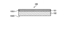
- FIG. 1 is a cross-sectional view schematically showing an embodiment F-1 of the optical laminated film.
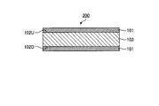
- FIG. 2 is a cross-sectional view schematically showing an embodiment F-2 of the optical laminated film.
- FIG. 3 is a cross-sectional view schematically showing an embodiment P-1 of the touch panel.
- FIG. 4 is a cross-sectional view schematically showing an embodiment P-2 of the touch panel.
- FIG. 5 is a cross-sectional view schematically showing an embodiment P-3 of the touch panel.
- FIG. 6 is a cross-sectional view schematically showing an embodiment P-4 of the touch panel.
- FIG. 7 is a cross-sectional view schematically showing an embodiment P-5 of the touch panel.
- nx represents the refractive index in the direction (in-plane direction) perpendicular to the thickness direction of the film and in the direction giving the maximum refractive index.
- ny represents the refractive index of the in-plane direction of the film, which is perpendicular to the nx direction.
- nz represents the refractive index in the thickness direction of the film.
- d represents the thickness of the film.
- the measurement wavelength of retardation is 590 nm unless otherwise stated.
- the optical laminate film of the present invention comprises at least one layer A containing a thermoplastic resin [A] and a layer B consisting of a thermoplastic resin [B], and the at least one layer A is at least one of the layers B. It is provided on the surface. That is, the optical laminated film of the present invention includes one or more B layers and one or more A layers provided on one or both surfaces of the B layer.
- the tensile rupture elongation Sa of the film (a1) having a thickness of 1.5 mm and the retardation Rthb in the thickness direction of the layer B and the thermoplastic resin [A] satisfies the following formulas (1) and (2).
- represents the absolute value of the retardation Rthb in the thickness direction of the B layer.
- thermoplastic resin [A] The thermoplastic resin [A] usually contains a thermoplastic polymer, and further contains optional components as required.
- the content of the thermoplastic polymer in the thermoplastic resin [A] is preferably 55% by weight or more, more preferably 60% by weight or more, based on the total weight of the thermoplastic resin [A], and more preferably Is 65% by weight or more.
- the content of the thermoplastic polymer in the thermoplastic resin [A] may be 100% by weight or less.
- thermoplastic resin [A] examples include aliphatic olefin polymers such as polyethylene and polypropylene; alicyclic olefin polymers; polyesters such as polyethylene terephthalate and polybutylene terephthalate; polyarylenes such as polyphenylene sulfide Sulfide; Polyvinyl alcohol; Polycarbonate; Polyarylate; Cellulose ester polymer; Polyether sulfone; Polysulfone; Polyaryl sulfone; Polyvinyl chloride; Rod-like liquid crystal polymer; Styrene or homopolymer of styrene derivative, or styrene or styrene derivative Polystyrene based polymers including copolymers with optional monomers; hydrides of copolymers of aromatic compounds such as styrene and conjugated dienes such as butadiene and isoprene (aromatic ring Including hydrides); polyacrylonit
- acrylonitrile for example, acrylonitrile, maleic anhydride, methyl methacrylate and butadiene can be mentioned.
- maleic anhydride methyl methacrylate and butadiene
- One of these may be used alone, or two or more of them may be used in combination at an arbitrary ratio.
- thermoplastic resin [A] preferably contains a block copolymer hydride [2] or an alkoxysilyl group modified product [3] of the block copolymer hydride [2].
- Block copolymer hydride [2] is a substance having a structure formed by hydrogenation of the following block copolymer [1].
- block copolymer hydride [2] is not limited by the manufacturing method.
- the block copolymer hydride [2] is also referred to as “hydride [2]”.
- the block copolymer [1] comprises two or more polymer blocks [C] per molecule of the block copolymer [1] and one or more polymer blocks per molecule of the block copolymer [1] D] is a block copolymer.
- Polymer block [C] is a polymer block containing an aromatic vinyl compound unit.
- the aromatic vinyl compound unit refers to a structural unit having a structure formed by polymerizing an aromatic vinyl compound.
- the aromatic vinyl compound unit is not limited by the production method.
- Examples of the aromatic vinyl compound corresponding to the aromatic vinyl compound unit possessed by the polymer block [C] include styrene; ⁇ -methylstyrene, 2-methylstyrene, 3-methylstyrene, 4-methylstyrene, and 2,4 Styrenes having an alkyl group having 1 to 6 carbon atoms as a substituent, such as -dimethylstyrene, 2,4-diisopropylstyrene, 4-t-butylstyrene, 5-t-butyl-2-methylstyrene, etc .; 4-chloro Styrenes having a halogen atom as a substituent, such as styrene, dichlorostyrene, 4-monofluorostyrene; styrenes having an alkoxy group having 1 to 6 carbon atoms as a substituent, such as 4-methoxystyrene; 4-phenylstyrene Etc., s
- aromatic vinyl compounds having no polar group such as styrene and styrenes having an alkyl group having 1 to 6 carbon atoms as a substituent are preferable because they can lower hygroscopicity, and industrial availability is easy to obtain From this, styrene is particularly preferred.
- the content of the aromatic vinyl compound unit in the polymer block [C] is preferably 90% by weight or more, more preferably 95% by weight or more, and particularly preferably 99% by weight or more.
- the amount of the aromatic vinyl compound units in the polymer block [C] is large as described above, the hardness and heat resistance of the layer A can be enhanced.
- the polymer block [C] may contain any structural unit in addition to the aromatic vinyl compound unit.
- the polymer block [C] may contain any one of structural units of one kind alone, or may contain two or more kinds of them in combination in an arbitrary ratio.
- a chain-like conjugated diene compound unit refers to a structural unit having a structure formed by polymerizing a chain conjugated diene compound.
- Examples of the chain conjugated diene compound corresponding to the chain conjugated diene compound unit include, for example, the same examples as the chain conjugated diene compound corresponding to the chain conjugated diene compound unit possessed by the polymer block [D]. It can be mentioned.
- the polymer block [C] may contain, for example, a structural unit having a structure formed by polymerizing an arbitrary unsaturated compound other than an aromatic vinyl compound and a chain conjugated diene compound It can be mentioned.
- the optional unsaturated compound include vinyl compounds such as linear vinyl compounds and cyclic vinyl compounds; unsaturated cyclic acid anhydrides; unsaturated imide compounds; and the like. These compounds may have a substituent such as a nitrile group, an alkoxycarbonyl group, a hydroxycarbonyl group or a halogen group.
- the content of any structural unit in the polymer block [C] is preferably 10% by weight or less, more preferably 5% by weight or less, and particularly preferably 1% by weight or less.
- the number of polymer blocks [C] in one molecule of block copolymer [1] is preferably 2 or more, preferably 5 or less, more preferably 4 or less, particularly preferably 3 or less.
- a plurality of polymer blocks [C] present in one molecule may be the same as or different from one another.
- the weight average molecular weight of the polymer block having the largest weight average molecular weight in the polymer block [C] is Mw
- (A1) be the weight average molecular weight of the polymer block with the smallest weight average molecular weight be Mw (A2).
- the ratio “Mw (A1) / Mw (A2)” of Mw (A1) to Mw (A2) is preferably 4.0 or less, more preferably 3.0 or less, particularly preferably 2.0 or less It is. Thereby, the variation in various physical property values can be reduced.
- Polymer block [D] is a polymer block containing a chain-like conjugated diene compound unit.
- the chain conjugated diene compound unit refers to a structural unit having a structure formed by polymerizing a chain conjugated diene compound.
- the chain conjugated diene compound unit is not limited by the production method.
- chain conjugated diene compound corresponding to a chain conjugated diene compound unit possessed by this polymer block [D] for example, 1,3-butadiene, isoprene, 2,3-dimethyl-1,3-butadiene, 1,1 3-pentadiene etc. are mentioned. One of these may be used alone, or two or more of them may be used in combination at an arbitrary ratio. Among them, a chain conjugated diene compound not containing a polar group is preferable because it can lower hygroscopicity, and 1,3-butadiene and isoprene are particularly preferable.
- the content of the chain conjugated diene compound unit in the polymer block [D] is preferably 70% by weight or more, more preferably 80% by weight or more, and particularly preferably 90% by weight or more.
- the flexibility of the layer A can be improved by increasing the amount of the chain-like conjugated diene compound unit in the polymer block [D] as described above.
- the polymer block [D] may contain any structural unit in addition to the chain conjugated diene compound unit.
- the polymer block [D] may contain any one of structural units singly or in combination, and may contain two or more of them in combination in an arbitrary ratio.
- the optional structural unit that may be included in the polymer block [D] is formed, for example, by polymerizing an aromatic vinyl compound unit, and an arbitrary unsaturated compound other than an aromatic vinyl compound and a chain conjugated diene compound.
- the structural unit which has a structure is mentioned. Examples of these aromatic vinyl compound units and structural units having a structure formed by polymerizing an arbitrary unsaturated compound are, for example, those exemplified as may be contained in the polymer block [C]. And the same example.
- the content of any structural unit in the polymer block [D] is preferably 30% by weight or less, more preferably 20% by weight or less, and particularly preferably 10% by weight or less.
- the low content of any structural unit in the polymer block [D] can improve the flexibility of the layer A.
- the number of polymer blocks [D] in one molecule of block copolymer [1] is usually one or more, but may be two or more. When the number of polymer blocks [D] in the block copolymer [1] is 2 or more, those polymer blocks [D] may be the same as or different from each other.
- the weight average molecular weight of the polymer block having the largest weight average molecular weight in the polymer block [D] is Mw
- (B1) be the weight average molecular weight of the polymer block with the smallest weight average molecular weight be Mw (B2).
- the ratio “Mw (B1) / Mw (B2)” of Mw (B1) to Mw (B2) is preferably 4.0 or less, more preferably 3.0 or less, particularly preferably 2.0 or less It is. Thereby, the variation in various physical property values can be reduced.
- the block form of the block copolymer [1] may be a chain block or a radial block. Among them, chain-type blocks are preferable because they have excellent mechanical strength.
- the block copolymer [1] has the form of a chain block, both ends of the molecular chain of the block copolymer [1] are the polymer block [C], and the tackiness of the layer A is desirably low. It is preferable because it can be suppressed to a value.
- a particularly preferable block form of the block copolymer [1] is a polymer block [C] bonded to both ends of the polymer block [D] as represented by [C]-[D]-[C].
- a triblock copolymer of [C]-[D]-[C] is particularly preferable because the production is easy and the physical properties can be easily contained in a desired range.
- the weight fraction wC of the polymer block [C] in the whole of the block copolymer [1] and the polymer block [D] in the whole of the block copolymer [1] The ratio (wC / wD) to the weight fraction wD of is within a specific range. Specifically, the ratio (wC / wD) is usually 20/80 or more, preferably 25/75 or more, more preferably 30/70 or more, particularly preferably 40/60 or more, and usually 60/40. Below, Preferably it is 55/45 or less.
- the ratio wC / wD is equal to or more than the lower limit value of the above range, the hardness and heat resistance of the layer A can be improved, or birefringence can be reduced. Moreover, the flexibility of A layer can be improved because said ratio wC / wD is below the upper limit of the said range.
- the weight fraction wC of the polymer block [C] represents the weight fraction of the whole polymer block [C]
- the weight fraction wB of the polymer block [C] represents the whole polymer block [C] Indicates the weight fraction of
- the weight average molecular weight (Mw) of the block copolymer [1] is preferably 40,000 or more, more preferably 50,000 or more, particularly preferably 60,000 or more, preferably 200,000 or less, More preferably, it is 150,000 or less, particularly preferably 100,000 or less.
- the molecular weight distribution (Mw / Mn) of the block copolymer [1] is preferably 3 or less, more preferably 2 or less, particularly preferably 1.5 or less, and preferably 1.0 or more.
- Mn represents a number average molecular weight.
- the weight average molecular weight (Mw) and the molecular weight distribution (Mw / Mn) of the block copolymer [1] are as polystyrene conversion values by gel permeation chromatography (GPC) using tetrahydrofuran (THF) as a solvent. It can be measured.
- a method for producing the block copolymer [1] for example, a monomer composition containing an aromatic vinyl compound (a) and a monomer composition containing a chain conjugated diene compound (b) by a method such as living anionic polymerization A method of polymerizing alternately); after polymerizing a monomer composition (a) containing an aromatic vinyl compound and a monomer composition (b) containing a chain conjugated diene compound in order, polymer block [D] A method of coupling the ends with a coupling agent;
- the content of the aromatic vinyl compound in the monomer composition (a) is preferably 90% by weight or more, more preferably 95% by weight or more, and particularly preferably 99% by weight or more.
- the monomer composition (a) may also contain any monomer component other than the aromatic vinyl compound.
- an optional monomer component for example, a chain conjugated diene compound and any unsaturated compound can be mentioned.
- the amount of the optional monomer component is preferably 10% by weight or less, more preferably 5% by weight or less, particularly preferably 1% by weight or less, based on the monomer composition (a).
- the content of the linear conjugated diene compound in the monomer composition (b) is preferably 70% by weight or more, more preferably 80% by weight or more, and particularly preferably 90% by weight or more.
- the monomer composition (b) may also contain any monomer component other than the chain conjugated diene compound.
- the optional monomer components include aromatic vinyl compounds and any unsaturated compounds.
- the amount of the optional monomer component is preferably at most 30 wt%, more preferably at most 20 wt%, particularly preferably at most 10 wt%, based on the monomer composition (b).
- radical polymerization, anion polymerization, cation polymerization, coordination anion polymerization, coordination cation polymerization etc. can be used, for example.
- a method of performing radical polymerization, anionic polymerization, cationic polymerization and the like by living polymerization is preferable, and a method of performing living anion polymerization is particularly preferable.
- the polymerization can be carried out in the presence of a polymerization initiator.
- a polymerization initiator for example, in living anionic polymerization, monoorganolithiums such as n-butyllithium, sec-butyllithium, t-butyllithium, hexyllithium and phenyllithium as polymerization initiators; dilithiomethane, 1,4-dilithiobutane, 1,4-dilithio Multifunctional organolithium compounds such as -2-ethylcyclohexane and the like can be used. One of these may be used alone, or two or more of them may be used in combination at an arbitrary ratio.
- the polymerization temperature is preferably 0 ° C. or more, more preferably 10 ° C. or more, particularly preferably 20 ° C. or more, preferably 100 ° C. or less, more preferably 80 ° C. or less, particularly preferably 70 ° C. or less.
- solution polymerization and slurry polymerization can be used as the form of the polymerization reaction. Above all, when solution polymerization is used, removal of reaction heat is easy. When solution polymerization is performed, an inert solvent in which the polymer obtained in each step can be dissolved can be used as the solvent.
- the inert solvent examples include aliphatic hydrocarbon solvents such as n-butane, n-pentane, isopentane, n-hexane, n-heptane, isooctane and the like; cyclopentane, cyclohexane, methylcyclopentane, methylcyclohexane, decalin, bicyclo [4.3.0] Alicyclic hydrocarbon solvents such as nonane and tricyclo [4.3.0.1 2,5 ] decane; aromatic hydrocarbon solvents such as benzene and toluene; and the like. One of these may be used alone, or two or more of them may be used in combination at an arbitrary ratio.
- aliphatic hydrocarbon solvents such as n-butane, n-pentane, isopentane, n-hexane, n-heptane, isooctane and the like
- an alicyclic hydrocarbon solvent as the solvent because it can be used as a solvent inert to the hydrogenation reaction as it is and the solubility of the block copolymer [1] is good.
- the amount of the solvent used is preferably 200 parts by weight to 2000 parts by weight with respect to 100 parts by weight of all the used monomers.
- a randomizer may be used to control the lengthening of only one component chain.
- a Lewis base compound it is preferable to use, for example, a Lewis base compound as a randomizer.
- Lewis base compounds include ether compounds such as dimethyl ether, diethyl ether, diisopropyl ether, dibutyl ether, tetrahydrofuran, diphenyl ether, ethylene glycol diethyl ether, ethylene glycol methyl phenyl ether; and the like; tetramethyl ethylene diamine, trimethyl amine, triethylamine, pyridine and the like Tertiary amine compounds; alkali metal alkoxide compounds such as potassium-t-amyl oxide and potassium-t-butyl oxide; phosphine compounds such as triphenylphosphine; and the like. One of these may be used alone, or two or more of them may be used in combination at an arbitrary ratio.
- the hydride [2] is a polymer having a structure formed by hydrogenating the unsaturated bond of the block copolymer [1].
- unsaturated bonds of the block copolymer [1] to be hydrogenated include carbon-carbon unsaturated bonds of the main chain and side chains of the block copolymer [1], and carbon-carbon of an aromatic ring Any unsaturated bond is included.
- the hydrogenation rate is preferably 90% or more, more preferably 97% or more, of the carbon-carbon unsaturated bond and aromatic carbon-carbon unsaturated bond in the main chain and side chain of the block copolymer [1]. Particularly preferably, it is 99% or more.
- the higher the degree of hydrogenation the better the transparency, the heat resistance and the weather resistance of the A layer, and the smaller the birefringence of the A layer.
- the hydrogenation rate of the hydride [2] can be determined by measurement by 1 H-NMR.
- the hydrogenation rate of the carbon-carbon unsaturated bond in the main chain and the side chain is preferably 95% or more, more preferably 99% or more.
- the light resistance and oxidation resistance of the layer A can be further enhanced by increasing the degree of hydrogenation of carbon-carbon unsaturated bonds in the main chain and side chains.
- the hydrogenation rate of the carbon-carbon unsaturated bond of the aromatic ring is preferably 90% or more, more preferably 93% or more, and particularly preferably 95% or more. Since the glass transition temperature of the polymer block obtained by hydrogenating the polymer block [C] is increased by increasing the hydrogenation rate of the carbon-carbon unsaturated bond of the aromatic ring, the heat resistance of the layer A is effectively reduced. Can be raised.
- the weight average molecular weight (Mw) of the hydride [2] is preferably 40,000 or more, more preferably 50,000 or more, particularly preferably 60,000 or more, preferably 200,000 or less, more preferably 150 Or less, particularly preferably 100,000 or less.
- Mw weight average molecular weight
- the molecular weight distribution (Mw / Mn) of the hydride [2] is preferably 3 or less, more preferably 2 or less, particularly preferably 1.5 or less, and preferably 1.0 or more.
- Mw / Mn molecular weight distribution of the hydride [2] falls within the above range, the mechanical strength and heat resistance of the A layer can be improved, and furthermore, the birefringence of the A layer can be easily reduced.
- the weight average molecular weight (Mw) and the molecular weight distribution (Mw / Mn) of the hydride [2] can be measured in terms of polystyrene by gel permeation chromatography (GPC) using tetrahydrofuran as a solvent.
- the hydride [2] described above can be produced by hydrogenating the block copolymer [1].
- a hydrogenation method which can increase the hydrogenation rate and has a small chain cleavage reaction of the block copolymer [1] is preferable.
- a hydrogenation method for example, the methods described in WO 2011/096389 and WO 2012/043708 can be mentioned.
- hydrogenation is carried out using a hydrogenation catalyst containing at least one metal selected from the group consisting of nickel, cobalt, iron, rhodium, palladium, platinum, ruthenium, and rhenium. How to do it.
- the hydrogenation catalyst may be used alone or in combination of two or more at an arbitrary ratio.
- the hydrogenation catalyst may be either a heterogeneous catalyst or a homogeneous catalyst.
- the hydrogenation reaction is preferably carried out in an organic solvent.
- the alkoxysilyl group modified product [3] is a polymer having a structure formed by introducing an alkoxysilyl group into the hydride [2] of the block copolymer [1] described above.
- the alkoxysilyl group modified product [3] is not limited by the production method.
- the alkoxysilyl group may be directly bonded to the above-mentioned hydride [2], or may be indirectly bonded via a divalent organic group such as an alkylene group.
- the modified alkoxysilyl group [3] into which an alkoxysilyl group is introduced is particularly excellent in adhesion to an inorganic material such as glass and metal. Therefore, the layer A is usually excellent in adhesion to the above-mentioned inorganic material.
- the amount of alkoxysilyl group introduced in the modified alkoxysilyl group [3] is preferably 0.1 parts by weight or more, more preferably 0.
- the amount is 2 parts by weight or more, particularly preferably 0.3 parts by weight or more, preferably 10 parts by weight or less, more preferably 5 parts by weight or less, and particularly preferably 3 parts by weight or less.
- the introduction amount of the alkoxysilyl group can be measured by 1 H-NMR spectrum.
- the introduction amount of the alkoxysilyl group when the introduction amount is small, the number of integrations can be increased to perform measurement.
- the modified alkoxysilyl group [3] can be produced by introducing an alkoxysilyl group into the hydride [2] of the block copolymer [1] described above.
- a method of introducing an alkoxysilyl group into hydride [2] for example, a method of reacting hydride [2] with an ethylenically unsaturated silane compound in the presence of peroxide can be mentioned.
- ethylenically unsaturated silane compound those which can graft-polymerize with hydride [2] and can introduce an alkoxysilyl group into hydride [2] can be used.
- ethylenically unsaturated silane compounds include vinyltrimethoxysilane, vinyltriethoxysilane, dimethoxymethylvinylsilane, and alkoxysilanes having a vinyl group such as diethoxymethylvinylsilane; allyltrimethoxysilane, allyltriethoxysilane Alkoxysilanes having an allyl group, etc .; alkoxysilanes having a p-styryl group such as p-styryltrimethoxysilane, p-styryltriethoxysilane, etc .; 3-methacryloxypropyltrimethoxysilane, 3-methacryloxypropylmethyldimethoxysilane
- Silane is preferred.
- an ethylenically unsaturated silane compound may be used individually by 1 type, and may be used combining two or more types by arbitrary ratios.
- the amount of the ethylenically unsaturated silane compound is preferably 0.1 parts by weight or more, more preferably 0.2 parts by weight or more, particularly preferably 100 parts by weight of the hydride [2] before introducing the alkoxysilyl group.
- the amount is preferably 0.3 parts by weight or more, preferably 10 parts by weight or less, more preferably 5 parts by weight or less, and particularly preferably 3 parts by weight or less.
- the proportion of the hydride [2] or the modified alkoxysilyl group [3] is preferably 80% by weight to 100% by weight, more preferably 90% by weight to 100% by weight, particularly preferably It is 95 wt% to 100 wt%.
- the tensile breaking elongation Sa of the film (a1) having a thickness of 1.5 mm formed from the thermoplastic resin [A] usually satisfies the following formula (2). (2) Sa 100 100%
- the tensile elongation at break Sa is usually 100% or more, preferably 200% or more, and more preferably 300% or more.
- the tensile elongation at break Sa can usually be 1000% or less.
- the tensile breaking elongation Sa and the tensile breaking elongation Sb described later can be measured in accordance with JIS K7127.
- the flexural modulus Ea of the film (a2) having a thickness of 4 mm formed of the thermoplastic resin [A] preferably satisfies the following formula (3). (3) 300 MPa ⁇ Ea ⁇ 900 MPa
- the flexural modulus Ea is preferably 300 MPa or more, more preferably 350 MPa or more, preferably 900 MPa or less, more preferably 850 MPa or less.
- a layer can be used as a layer which has a softness
- the flexural modulus Ea and the flexural modulus Eb described later can be measured in accordance with JIS K7171.
- thermoplastic resin [A] A layer may contain arbitrary components other than thermoplastic resin [A].
- Optional components include, for example, liquid paraffin such as hydrogenated polybutene.
- the amount of optional components other than the thermoplastic resin [A] in the layer A is preferably 45% by weight or less, more preferably 40% by weight or less.
- Optional components other than the thermoplastic resin [A] in the layer A may be 0% by weight or more.
- the layer B is made of a thermoplastic resin [B], preferably formed of only a thermoplastic resin [B].
- thermoplastic resin [B] The thermoplastic resin [B] usually contains a thermoplastic polymer, and further contains optional components as required.
- the content of the thermoplastic polymer in the thermoplastic resin [B] is preferably 55% by weight or more, more preferably 60% by weight or more, based on the total weight of the thermoplastic resin [B]. Preferably it is 65 weight% or more.
- the content of the thermoplastic polymer in the thermoplastic resin [B] may be 100% by weight or less.
- thermoplastic resin [B] As a polymer contained in thermoplastic resin [B], the polymer mentioned as a polymer contained in thermoplastic resin [A] is mentioned, for example.
- the thermoplastic resin [B] has an alicyclic structure (also referred to as an alicyclic ring structure) in that it is excellent in mechanical properties, heat resistance, transparency, low hygroscopicity, low moisture permeability, dimensional stability, and lightness. It is preferable to contain the polymer to contain.
- the polymer containing an alicyclic structure is a polymer in which the structural unit of the polymer contains an alicyclic structure.
- the polymer having an alicyclic structure may have an alicyclic structure in the main chain, may have an alicyclic structure in a side chain, and may have an oil in both the main chain and the side chain. It may have a cyclic structure.
- polymers having an alicyclic structure at least in the main chain are preferable from the viewpoint of mechanical strength and heat resistance.
- alicyclic structure a saturated alicyclic hydrocarbon (cycloalkane) structure, unsaturated alicyclic hydrocarbon (cycloalkene, cycloalkyne) structure etc. are mentioned, for example.
- a cycloalkane structure and a cycloalkene structure are preferable from the viewpoint of mechanical strength and heat resistance, and a cycloalkane structure is particularly preferable among them.
- the number of carbon atoms constituting the alicyclic structure per one alicyclic structure is preferably 4 or more, more preferably 5 or more, preferably 30 or less, more preferably 20 or less, particularly preferably Is in the range of 15 or less.
- the proportion of structural units having an alicyclic structure can be appropriately selected depending on the purpose of use.
- polymers having an alicyclic structure examples include norbornene polymers, monocyclic cyclic olefin polymers, cyclic conjugated diene polymers, vinyl alicyclic hydrocarbon polymers, and hydrides thereof. It can be mentioned. Among these, norbornene-based polymers are more preferable because of their good transparency and moldability.
- Examples of the norbornene-based polymer include a ring-opening polymer of a monomer having a norbornene structure and a hydride thereof; an addition polymer of a monomer having a norbornene structure and a hydride thereof.
- a ring-opening polymer of a monomer having a norbornene structure a ring-opening homopolymer of one kind of monomer having a norbornene structure, a ring-opening of two or more kinds of monomers having a norbornene structure Copolymers and ring-opened copolymers of monomers having a norbornene structure and any monomers copolymerizable therewith can be mentioned.
- an addition polymer of a monomer having a norbornene structure an addition homopolymer of one type of monomer having a norbornene structure, an addition copolymer of two or more types of monomers having a norbornene structure And addition copolymers of monomers having a norbornene structure and optional monomers copolymerizable therewith.
- a hydride of a ring-opening polymer of a monomer having a norbornene structure is particularly preferable from the viewpoint of moldability, heat resistance, low hygroscopicity, low moisture permeability, dimensional stability and lightness. .
- bicyclo [2.2.1] hept-2-ene (common name: norbornene), tricyclo [4.3.0.1 2,5 ] deca-3,7 -Diene (conventional name: dicyclopentadiene), 7,8-benzotricyclo [4.3.0.1 2,5 ] dec-3-ene (conventional name: methanotetrahydrofluorene), tetracyclo [4.4. 0.1 2,5 . 17 10 ] dodeca-3-ene (common name: tetracyclododecene), and derivatives of these compounds (eg, those having a substituent on the ring) and the like can be mentioned.
- an alkyl group, an alkylene group, a polar group etc. can be mentioned, for example. These substituents may be the same or different and a plurality may be bonded to the ring.
- the monomer having a norbornene structure one type may be used alone, or two or more types may be used in combination in an arbitrary ratio.
- the type of polar group includes, for example, a hetero atom or an atomic group having a hetero atom.
- a hetero atom an oxygen atom, a nitrogen atom, a sulfur atom, a silicon atom, a halogen atom etc. are mentioned, for example.
- Specific examples of the polar group include carboxyl group, carbonyloxycarbonyl group, epoxy group, hydroxyl group, oxy group, ester group, silanol group, silyl group, amino group, nitrile group, sulfonic acid group and the like.
- Examples of monomers having a norbornene structure and monomers capable of ring-opening copolymerization include monocyclic olefins such as cyclohexene, cycloheptene and cyclooctene and derivatives thereof; cyclic conjugated dienes such as cyclohexadiene and cycloheptadiene; Derivatives thereof; and the like.
- the monomer having a norbornene structure and the monomer capable of ring-opening copolymerization may be used alone or in combination of two or more at an arbitrary ratio.
- the ring-opening polymer of a monomer having a norbornene structure can be produced, for example, by polymerizing or copolymerizing the monomer in the presence of a ring-opening polymerization catalyst.
- Examples of the monomer capable of addition copolymerization with the monomer having a norbornene structure include ⁇ -olefins of 2 to 20 carbon atoms such as ethylene, propylene and 1-butene and derivatives thereof; cyclobutene, cyclopentene and cyclohexene And cycloolefins thereof and derivatives thereof; non-conjugated dienes such as 1,4-hexadiene, 4-methyl-1,4-hexadiene and 5-methyl-1,4-hexadiene; and the like.
- ⁇ -olefins are preferable, and ethylene is more preferable.
- the monomer having a norbornene structure and the monomer that can be addition-copolymerized may be used alone or in combination of two or more at an arbitrary ratio.
- the addition polymer of a monomer having a norbornene structure can be produced, for example, by polymerizing or copolymerizing the monomer in the presence of an addition polymerization catalyst.
- the hydrides of the ring-opening polymer and the addition polymer described above are, for example, a solution of the ring-opening polymer and the addition polymer in the presence of a hydrogenation catalyst containing a transition metal such as nickel and palladium. Saturated bonds may be prepared, preferably by hydrogenation of 90% or more.
- the polymer containing the above-mentioned alicyclic structure may be crystalline or amorphous.
- the polymer having crystallinity means a polymer having a melting point, that is, the melting point can be measured by a differential scanning calorimeter (DSC).
- DSC differential scanning calorimeter
- the melting point of the polymer is preferably 200 ° C. or more, more preferably 230 ° C. or more, and preferably 290 ° C. or less.
- the resin [B] contains a polymer containing an alicyclic structure having such a melting point, a B layer excellent in the balance between moldability and heat resistance can be obtained.
- the proportion of the polymer having an alicyclic structure is preferably 80% by weight to 100% by weight, more preferably 90% by weight to 100% by weight, particularly preferably 95% by weight It is 100% by weight.
- the flexural modulus Eb of the film (b) having a thickness of 4 mm formed of the thermoplastic resin [B] preferably satisfies the following formula (4). (4) 2200 MPa ⁇ Eb ⁇ 2800 MPa
- the flexural modulus Eb is preferably 2200 MPa or more, more preferably 2250 MPa or more, preferably 2800 MPa or less, more preferably 2700 MPa or less.
- the retardation Rthb in the thickness direction of the layer B usually satisfies the following formula (1).
- ) of retardation Rthb is usually 0 nm or more, usually 40 nm or less, preferably 30 nm or less, and more preferably 20 nm or less.
- the tensile breaking elongation Sb of the B layer preferably satisfies the following formula (5). (5) 5% ⁇ Sb ⁇ 60%
- the bending resistance can be improved by laminating the layer A.
- the tensile elongation at break Sb is preferably 5% or more, more preferably 6% or more, preferably 60% or less, and more preferably 58% or less.
- the optical laminate film may contain, in addition to the layer A and the layer B, any layer depending on the purpose of use of the optical laminate film.
- the optional layer includes, for example, an index matching layer and a hard coat layer.
- Embodiment F-1 of the optical laminated film the A layer is provided on one surface of the B layer.
- FIG. 1 is a cross-sectional view schematically showing an embodiment F-1 of the optical laminated film.
- the optical laminate film 100 includes an A layer 101 and a B layer 102.
- the B layer 102 has a surface 102U and a surface 102D, and the A layer 101 is provided directly on one surface 102U of the B layer 102.
- the optical laminate film includes two A layers, and an A layer is provided on each of both sides of the B layer.
- FIG. 2 is a cross-sectional view schematically showing an embodiment F-2 of the optical laminated film.
- the optical laminate film 200 includes an A layer 101, a B layer 102, and an A layer 101 in this order, and the two A layers 101 and 101 are directly on the surface 102U or 102D, respectively. It is provided.
- the optical laminate film can be produced by any method. For example, the method of forming A layer and B layer separately, laminating, and the method of manufacturing A layer and B layer simultaneously by methods, such as a coextrusion method and a co-casting method, and obtaining a lamination film are mentioned.
- layer A or layer B for example, a melt extrusion method, and a solution containing a material of layer A or layer B and a solvent are applied to a support film having a surface subjected to a mold release treatment.
- the method of forming and then removing a solvent from a coating layer, and obtaining the A layer or B layer with a support film is mentioned.
- a method of laminating separately formed A layer and B layer for example, a method of pressing and bonding A layer and B layer while heating, a method of bonding A layer and B layer via an adhesive layer Can be mentioned.
- the surface of the A layer or the B layer may be subjected to surface treatment such as corona treatment.
- the support film When manufacturing a laminated film from A layer or B layer with a support film, the support film may be removed before laminating A layer and B layer, or A layer or B layer is left with a support film. After laminating to obtain a laminate, the support film may be removed from the laminate to obtain an optical laminate film.
- the optical laminated film of the present invention can be used in various optical applications. For example, it can be used as a member of a touch panel.
- the optical laminated film of the present invention is excellent in bending resistance, so that it is particularly flexible in combination with a flexible image display element (flexible display element), such as a flexible touch panel.
- the device can be
- the touch panel of the present invention includes a touch sensor member and an image display element.
- the touch sensor member includes a first conductive layer, the optical laminated film, and a second conductive layer in this order.
- the touch sensor member is provided on the viewing side of the image display element.
- a touch sensor member forms a 2nd conductive layer on the said optical laminated film, and bonds the optical laminated film in which the 2nd conductive layer was formed to the 1st conductive layer through a dielectric.
- the second conductive layer formed on another base (for example, a glass base or a film base) in the laminate including the first conductive layer and the above optical laminated film It may be bonded via a dielectric.
- the first conductive layer and / or the second conductive layer may be a layer obtained by transferring the conductive layer formed on another substrate to the above-mentioned optical laminated film.
- any image display element can be used, and examples thereof include a liquid crystal display element and an organic electroluminescent (organic EL) display element.
- an image display element an element having a structure capable of curving the surface on the visual side of the image display element inside, an element having a structure capable of curving the surface on the visual side of the image display element outside It is possible to use an element having a structure that can be curved such that the surface on the viewing side of the display element is on the inside and the surface on the viewing side of the image display element is on the outside.
- the image display element is preferably an image display element having flexibility.
- the first conductive layer and the second conductive layer are layers having conductivity.
- the layer having conductivity is generally formed as a layer including a material having conductivity (conductive material).
- Conductive materials include, for example, metals, conductive metal oxides, conductive nanowires, and conductive polymers. As the conductive material, one type may be used alone, or two or more types may be used in combination in an arbitrary ratio.
- the planar shape of the conductive layer is preferably a pattern which operates well as a touch panel (for example, a capacitive touch panel).
- a touch panel for example, a capacitive touch panel.
- the conductive layer preferably has high transparency.
- composition of a touch panel is explained using a drawing.
- the present invention is not limited by these configuration examples, and may include other components as needed.
- functional layers such as an index matching layer and a hard coat layer may be included as other components.
- the touch panel includes a touch sensor member and an image display element.
- the touch sensor member includes a first conductive layer, an optical laminated film, and a second conductive layer in this order.
- the touch sensor member is provided on the viewing side of the image display element, and the touch sensor member is disposed such that the surface on the viewing side of the image display element faces the surface on the A layer side of the optical laminated film. ing.
- FIG. 3 is a cross-sectional view schematically showing an embodiment P-1 of the touch panel.
- the touch panel 300 includes an image display element 301 and a touch panel member 350.
- the touch panel member 350 is directly provided on the surface 301 U on the viewing side of the image display element 301.
- the touch panel member 350 includes the conductive layer 302, the optical laminated film 100, and the conductive layer 303 in this order.
- the optical laminated film 100 includes a B layer 102 and an A layer 101 provided directly on one side of the B layer 102.
- the surface 101 D on the A layer 101 side of the optical laminated film 100 is opposed to the surface 301 U on the viewing side of the image display element 301.
- the touch panel includes a touch sensor member and an image display element.
- the touch sensor member includes the first conductive layer, the optical laminated film, and the second conductive layer in this order, and the touch sensor member is provided on the viewing side of the image display element in the embodiment P-.
- This embodiment is the same as the embodiment 1 but differs from the embodiment P-1 in that the touch sensor member is disposed such that the surface on the viewing side of the image display element faces the surface on the B layer side of the optical laminated film. .
- FIG. 4 is a cross-sectional view schematically showing an embodiment P-2 of the touch panel.
- the touch panel 400 includes an image display element 301 and a touch panel member 450.
- the touch panel member 450 is directly provided on the surface 301 U on the viewing side of the image display element 301.
- the touch panel member 450 includes the conductive layer 302, the optical laminated film 100, and the conductive layer 303 in this order.
- the surface 102 D on the B layer 102 side of the optical laminated film 100 is opposed to the surface 301 U on the viewing side of the image display element 301.
- Embodiment P-3 of the touch panel includes a touch sensor member and an image display element, and the touch sensor member includes two layers A as an optical laminated film, and each of the layers B is on both sides. , A film is provided.
- FIG. 5 is a cross-sectional view schematically showing an embodiment P-3 of the touch panel.
- the touch panel 500 includes an image display element 301 and a touch panel member 550.
- the touch panel member 550 is directly provided on the surface 301 U on the viewing side of the image display element 301.
- the touch panel member 550 includes the conductive layer 302, the optical laminated film 200, and the conductive layer 303 in this order.
- the surface 101 D on one side of the optical laminated film 200 faces the surface 301 U on the viewing side of the image display element 301.
- Embodiment P-4 of the touch panel is an element having a configuration in which the touch panel includes a touch sensor member and an image display element, and the image display element can be curved with the surface on the viewing side facing inward.
- the touch sensor member is disposed such that the surface on the viewing side of the image display element faces the surface on the A layer side of the optical laminated film included in the touch sensor member.
- FIG. 6 is a cross-sectional view schematically showing an embodiment P-4 of the touch panel.
- the touch panel 600 includes an image display element 601 and a touch panel member 650.
- the touch panel member 650 is directly provided on the surface 601 U on the viewing side of the image display element 601.
- the image display element 601 has a configuration that can be curved with the surface 601U on the viewing side turned inside. Further, the touch panel member 650 is configured to have flexibility. Therefore, the touch panel 600 can also be curved with the surface 601 U on the viewing side of the image display element 601 inside.
- the form shown by the solid line in FIG. 6 schematically shows the form when the touch panel 600 is bent, and the form shown by the dotted line schematically shows the form before the touch panel 600 is bent.
- the touch panel member 650 includes the conductive layer 602, the optical laminated film 100, and the conductive layer 603 in this order.
- the surface 101 D on the A layer 101 side of the optical laminated film 100 is opposed to the surface 601 U on the viewing side of the image display element 601.
- the touch panel 600 when the touch panel 600 is curved with the surface 601 U on the viewing side of the image display element 601 inside, a tensile stress is applied to the A layer 101 included in the optical laminated film 100. Even when the optical laminated film 100 is repeatedly bent so that tensile stress is repeatedly applied to the A layer 101, the occurrence of cracks is suppressed. Therefore, the touch panel 600 is excellent in bending resistance.
- Embodiment P-5 of the touch panel is an element having a configuration in which the touch panel includes a touch sensor member and an image display element, and the image display element can be curved with the surface on the viewing side outward.
- the touch sensor member is disposed such that the surface on the viewing side of the image display element faces the surface on the B layer side of the optical laminated film included in the touch sensor member.
- FIG. 7 is a cross-sectional view schematically showing an embodiment P-5 of the touch panel.
- the touch panel 700 includes an image display element 701 and a touch panel member 750.
- the touch panel member 750 is directly provided on the surface 701 U on the viewing side of the image display element 701.
- the image display element 701 has a configuration that can be curved with the surface 701U on the viewing side set to the outside. Further, the touch panel member 750 is configured to have flexibility. Therefore, the touch panel 700 can also be curved with the surface 701U on the viewing side of the image display element 701 on the outside.
- the form shown by the solid line in FIG. 7 schematically shows the form when the touch panel 700 is bent, and the form shown by the dotted line schematically shows the form before the touch panel 700 is bent.
- the touch panel member 750 includes the conductive layer 702, the optical laminated film 100, and the conductive layer 703 in this order.
- the surface 102 D on the B layer 102 side of the optical laminated film 100 is opposed to the surface 701 U on the viewing side of the image display element 701.
- the touch panel 700 when the touch panel 700 is curved with the surface 701U on the viewing side of the image display element 701 on the outside, tensile stress is applied to the A layer 101 included in the optical laminated film 100. Even when the optical laminated film 100 is repeatedly bent so that tensile stress is repeatedly applied to the A layer 101, the occurrence of cracks is suppressed. Therefore, the touch panel 700 is excellent in bending resistance.
- the weight average molecular weight and the number average molecular weight of the polymer were measured as polystyrene equivalent values using a gel permeation chromatography (GPC) system (“HLC-8320” manufactured by Tosoh Corporation).
- GPC gel permeation chromatography
- H-type column manufactured by Tosoh Corporation
- tetrahydrofuran was used as a solvent.
- the temperature at the time of measurement was 40.degree.
- the flexural modulus of the film to be measured was measured in accordance with JIS K7171. From the resin to be measured, a 4 mm sheet-like film was formed by injection molding, and this was used as a measurement sample. A tensile tester ("Model 5564" manufactured by Instron Corporation) was used as a measuring apparatus.
- a film having a thickness of 4 mm was formed by injection molding from the obtained modified product (a1-s), and the flexural modulus was measured.
- the flexural modulus was 437 MPa.
- a film having a thickness of 1.5 mm was formed by injection molding from the obtained modified product (a1-s), and the tensile elongation at break was measured. The tensile elongation at break was 520%.
- the reaction solution obtained by the hydrogenation reaction contained a hydrogenated block copolymer (a2 ′).
- the Mw (a2 ′) of the hydrogenated block copolymer (a2 ′) was 71,800, the molecular weight distribution Mw / Mn was 1.30, and the hydrogenation rate was almost 100%.
- the reaction solution is filtered to remove the hydrogenation catalyst, and then pentaerythrityl tetrakis [3- (3,5-di-t-butyl-4-hydroxyphenyl), which is a phenolic antioxidant, is removed.
- pentaerythrityl tetrakis [3- (3,5-di-t-butyl-4-hydroxyphenyl), which is a phenolic antioxidant, is removed.
- Propionate 2.0 parts of a xylene solution in which 0.3 part of (product name "AO60", manufactured by ADEKA Corporation) was dissolved was added and dissolved to obtain a solution.
- the above solution is treated at a temperature of 260 ° C.
- Example 1 (Production of optical laminated film) (Manufacture of layer A) 28 g of pellets of alkoxysilyl modified product (a1-s) of triblock copolymer hydride obtained in Production Example 2 and 12 g of hydrogenated polybutene ("PEARLream (registered trademark) 24" manufactured by NOF Corporation) and cyclohexane The mixture was mixed with 60 g, the pellet was dissolved, and a 40% polymer solution was prepared. The obtained polymer solution was applied to the release surface of a film (50 ⁇ m in thickness) made of polyethylene terephthalate (PET) for release, the surface of which was subjected to release treatment.
- PEARLream registered trademark
- PEARLream registered trademark
- cyclohexane hydrogenated polybutene
- the obtained polymer solution was applied to the release surface of a film (50 ⁇ m in thickness) made of polyethylene terephthalate (PET) for release, the surface of which was subjected to
- the application thickness of the solution was adjusted so that the thickness of the obtained A layer was 11 ⁇ m. After the application, it was dried on a hot plate at 110 ° C. for 30 minutes to form a laminate having a layer structure of (releasing film) / (A layer).
- layer B (Production of layer B)
- a layer B composed of a thermoplastic resin B cycloolefin polymer film (1) ("Zeonor film ZF16" manufactured by Nippon Zeon Co., Ltd .; bending elastic modulus 2500 MPa, tensile elongation at break 9%, thickness 50 ⁇ m) , Retardation in the thickness direction Rth 10 nm) was prepared. Further, the surface of the layer B to which the layer A was to be bonded was subjected to a corona treatment with an output at which the water contact angle was 45 degrees or less.
- the optical laminated film was mounted on an on-cell display panel to confirm the presence or absence of rainbow unevenness. Moreover, the bending resistance test was done about the said optical laminated film. The results are shown in Table 1.
- Example 2 (Production of layer B), instead of cycloolefin polymer film (1), cycloolefin polymer film (2) ("Zeonor film ZF14" manufactured by Nippon Zeon Co., bending elastic modulus 2350 MPa when thickness is 4 mm, tensile fracture An optical laminated film was obtained and evaluated in the same manner as in Example 1 except that an elongation of 55%, a thickness of 45 ⁇ m, and a retardation Rth of 5 nm in the thickness direction were used. The results are shown in Table 1.
- Example 3 (Production of layer B), instead of cycloolefin polymer film (1), cycloolefin polymer film (3) ("Zeonor film ZF16" manufactured by Nippon Zeon Co., Ltd .; flexural modulus of 2500 MPa when tensile thickness is 4 mm, tensile fracture
- An optical laminated film was obtained and evaluated in the same manner as in Example 1 except that an elongation of 21%, a thickness of 35 ⁇ m, and a retardation Rth of 10 nm in the thickness direction were used. The results are shown in Table 1.
- Example 4 In (Preparation of layer B), both sides of layer B are subjected to corona treatment to form a configuration of (releasing film) / (layer A) / (layer B) / (layer A) / (layer releasing film) And an optical laminated film having a configuration of (A layer) / (B layer) / (A layer) in the same manner as in Example 1 except that the B layer and two A layers are bonded to each other, and evaluation Did. The results are shown in Table 1.
- Example 5 Pellets of triblock copolymer hydride (a1) obtained in Production Example 1 in place of pellets of alkoxysilyl modified product of triblock copolymer hydride (a1-s) in (Production of A layer) In (Production of layer B), instead of cycloolefin polymer film (1), cycloolefin polymer film (3) ("Zeonor film ZF16" manufactured by Nippon Zeon Co., Ltd .; flexural modulus of elasticity when the thickness is 4 mm, 2500 MPa An optical laminated film was obtained and evaluated in the same manner as in Example 1 except that a tensile elongation at break 21%, a thickness 35 ⁇ m, and a retardation Rth 10 nm in the thickness direction were used. The results are shown in Table 1.
- Comparative Example 1 Evaluation was performed in the same manner as in Example 1 using the cycloolefin polymer film (1) instead of the optical laminated film. The results are shown in Table 2.
- Comparative Example 2 Evaluation was performed in the same manner as in Example 1 using the cycloolefin polymer film (2) instead of the optical laminated film. The results are shown in Table 2.
- Comparative Example 4 A polyethylene terephthalate film (“Cosmo Shine A4100” manufactured by Toyobo Co., Ltd., bending elastic modulus 5100 MPa when thickness is 4 mm, tensile elongation at break 110%, thickness 50 ⁇ m, thickness direction retardation Rth 1500 nm) is used instead of the optical laminated film. The evaluation was performed in the same manner as in Example 1. The results are shown in Table 2.
- a1 triblock copolymer hydride (a1) a1-s: Alkoxysilyl modified product of triblock copolymer hydride (a1-s)
- Film (1) cycloolefin polymer film (1)
- Film (2) cycloolefin polymer film (2)
- Film (3) cycloolefin polymer film (3)
- PET polyethylene terephthalate wC / wD: ratio of weight fraction wC to weight fraction wD in block copolymer which is a raw material of resin
- a Ea flexural modulus measured on a 4 mm thick film made of resin
- Sa Tensile elongation at break measured on 1.5 mm thick film consisting of resin
- a sb Tensile measured on layer B Elongation at break
- the film of Comparative Example 4 in which the retardation Rthb in the thickness direction does not satisfy the formula (1) is attached to the display panel, rainbow unevenness is observed, and the film is bent to 100 ⁇ 10 3 times. It can be seen that creases and cloudiness are observed.
- the optical laminated film of Comparative Example 3 in which the tensile elongation at break Sa does not satisfy the formula (2) also causes cracks in the film with a significantly smaller number of bending as compared with the optical laminated film of the example. I understand. Therefore, the above results show that the flexibility of the optical laminated film of the present invention is good.
Landscapes
- Chemical & Material Sciences (AREA)
- Engineering & Computer Science (AREA)
- Health & Medical Sciences (AREA)
- Chemical Kinetics & Catalysis (AREA)
- Medicinal Chemistry (AREA)
- Polymers & Plastics (AREA)
- Organic Chemistry (AREA)
- Physics & Mathematics (AREA)
- Theoretical Computer Science (AREA)
- General Engineering & Computer Science (AREA)
- General Physics & Mathematics (AREA)
- Manufacturing & Machinery (AREA)
- Human Computer Interaction (AREA)
- Materials Engineering (AREA)
- Optics & Photonics (AREA)
- Mechanical Engineering (AREA)
- General Chemical & Material Sciences (AREA)
- Laminated Bodies (AREA)
- Optical Elements Other Than Lenses (AREA)
- Graft Or Block Polymers (AREA)
- Addition Polymer Or Copolymer, Post-Treatments, Or Chemical Modifications (AREA)
Abstract
光学積層フィルム(100)は、熱可塑性樹脂[A]を含む少なくとも1つのA層(101)及び熱可塑性樹脂[B]からなるB層(102)を含み、前記少なくとも1つのA層が、前記B層の少なくとも一方の面上に設けられており、前記B層の厚み方向のレターデーションRthbが下式(1)を満たし、前記熱可塑性樹脂[A]からなる厚み1.5mmのフィルム(a1)の引張破断伸度Saが、下記式(2)を満たす。(1)|Rthb|≦40nm。(2)Sa≧100%。
Description
本発明は、光学積層フィルム及びタッチパネルに関する。
光学フィルムは、用途によっては折り曲げて使用されることがあるため、耐屈曲性を備えた光学フィルムの開発が行われている(特許文献1、2)。
しかし、特許文献1及び2の技術では、屈曲性が良好でない光学フィルムの耐屈曲性を十分に向上させることができなかった。
更に、近年、可撓性のある画像表示素子の開発が進み、画像表示素子を含むタッチパネルの部材にも耐屈曲性が求められている。
更に、近年、可撓性のある画像表示素子の開発が進み、画像表示素子を含むタッチパネルの部材にも耐屈曲性が求められている。
したがって、耐屈曲性が良好な光学積層フィルムが求められている。
本発明者らは、上記課題を解決するため鋭意検討した結果、熱可塑性樹脂[B]からなるB層の少なくとも一方の面上に、所定の厚みのフィルムとした場合の引張破断伸度が所定値以上である熱可塑性樹脂を含むA層を設けることにより、上記課題が解決できることを見出し、本発明を完成した。即ち、本発明は、以下を提供する。
[1] 熱可塑性樹脂[A]を含む少なくとも1つのA層及び熱可塑性樹脂[B]からなるB層を含み、
前記少なくとも1つのA層が、前記B層の少なくとも一方の面上に設けられており、
前記B層の厚み方向のレターデーションRthbが下式(1)を満たし、
前記熱可塑性樹脂[A]からなる厚み1.5mmのフィルム(a1)の引張破断伸度Saが、下記式(2)を満たす、光学積層フィルム。
(1)|Rthb|≦40nm
(2)Sa≧100%
[2] 前記熱可塑性樹脂[A]からなる厚み4mmのフィルム(a2)の曲げ弾性率Eaが下記式(3)を満たし、
前記熱可塑性樹脂[B]からなる厚み4mmのフィルム(b)の曲げ弾性率Ebが、下記式(4)を満たす、[1]に記載の光学積層フィルム。
(3)300MPa≦Ea≦900MPa
(4)2200MPa≦Eb≦2800MPa
[3] 前記熱可塑性樹脂[A]が、ブロック共重合体水素化物[2]又は前記ブロック共重合体水素化物[2]のアルコキシシリル基変性物[3]を含み、
前記ブロック共重合体水素化物[2]は、ブロック共重合体[1]が水素化されて形成される構造を有する物質であり、
前記ブロック共重合体[1]は、芳香族ビニル化合物単位を含有する、前記ブロック共重合体[1]の1分子当たり2個以上の重合体ブロック[C]と、鎖状共役ジエン化合物単位を含有する、前記ブロック共重合体[1]1分子あたり1個以上の重合体ブロック[D]とを有し、前記ブロック共重合体[1]の全体に占める前記重合体ブロック[C]の重量分率wCと、前記ブロック共重合体[1]の全体に占める前記重合体ブロック[D]の重量分率wDとの比(wC/wD)が、30/70~60/40であり、
前記ブロック共重合体水素化物[2]は、前記ブロック共重合体[1]の主鎖及び側鎖の炭素-炭素不飽和結合及び芳香環の炭素-炭素不飽和結合が水素化されている物質である、[1]又は[2]に記載の光学積層フィルム。
[4] 前記熱可塑性樹脂[A]が、前記ブロック共重合体水素化物[2]のアルコキシシリル基変性物[3]を含む、[3]に記載の光学積層フィルム。
[5] 前記B層の引張破断伸度Sbが、下記式(5)を満たす、[1]~[4]のいずれか1項に記載の光学積層フィルム。
(5)5%≦Sb≦60%
[6] 前記熱可塑性樹脂[B]が、脂環式構造を含有する重合体を含む、[1]~[5]のいずれか1項に記載の光学積層フィルム。
[7] 前記A層を2つ含み、前記B層の両面のそれぞれの上に、前記A層が設けられている、[1]~[6]のいずれか1項に記載の光学積層フィルム。
[8] タッチセンサ部材と、画像表示素子とを含むタッチパネルであって、
前記タッチセンサ部材が、第1導電性層、[1]~[7]のいずれか1項の光学積層フィルム、及び第2導電性層をこの順で含み、前記画像表示素子の視認側に設けられている、タッチパネル。
[9] タッチセンサ部材と、画像表示素子とを含むタッチパネルであって、
前記タッチセンサ部材が、第1導電性層、[1]~[6]のいずれか1項の光学積層フィルム、及び第2導電性層をこの順で含み、前記画像表示素子の視認側に設けられており、
前記画像表示素子が、視認側の面を内側にして湾曲可能であり、
前記画像表示素子の前記視認側の面と、前記光学積層フィルムの前記A層側の面が対向するように前記タッチセンサ部材が配置されている、タッチパネル。
[10] タッチセンサ部材と、画像表示素子とを含むタッチパネルであって、
前記タッチセンサ部材が、第1導電性層、[1]~[6]のいずれか1項の光学積層フィルム、及び第2導電性層をこの順で含み、前記画像表示素子の視認側に設けられており、
前記画像表示素子が、視認側の面を外側にして湾曲可能であり、
前記画像表示素子の前記視認側の面と、前記光学積層フィルムの前記B層側の面が対向するように前記タッチセンサ部材が配置されている、タッチパネル。
前記少なくとも1つのA層が、前記B層の少なくとも一方の面上に設けられており、
前記B層の厚み方向のレターデーションRthbが下式(1)を満たし、
前記熱可塑性樹脂[A]からなる厚み1.5mmのフィルム(a1)の引張破断伸度Saが、下記式(2)を満たす、光学積層フィルム。
(1)|Rthb|≦40nm
(2)Sa≧100%
[2] 前記熱可塑性樹脂[A]からなる厚み4mmのフィルム(a2)の曲げ弾性率Eaが下記式(3)を満たし、
前記熱可塑性樹脂[B]からなる厚み4mmのフィルム(b)の曲げ弾性率Ebが、下記式(4)を満たす、[1]に記載の光学積層フィルム。
(3)300MPa≦Ea≦900MPa
(4)2200MPa≦Eb≦2800MPa
[3] 前記熱可塑性樹脂[A]が、ブロック共重合体水素化物[2]又は前記ブロック共重合体水素化物[2]のアルコキシシリル基変性物[3]を含み、
前記ブロック共重合体水素化物[2]は、ブロック共重合体[1]が水素化されて形成される構造を有する物質であり、
前記ブロック共重合体[1]は、芳香族ビニル化合物単位を含有する、前記ブロック共重合体[1]の1分子当たり2個以上の重合体ブロック[C]と、鎖状共役ジエン化合物単位を含有する、前記ブロック共重合体[1]1分子あたり1個以上の重合体ブロック[D]とを有し、前記ブロック共重合体[1]の全体に占める前記重合体ブロック[C]の重量分率wCと、前記ブロック共重合体[1]の全体に占める前記重合体ブロック[D]の重量分率wDとの比(wC/wD)が、30/70~60/40であり、
前記ブロック共重合体水素化物[2]は、前記ブロック共重合体[1]の主鎖及び側鎖の炭素-炭素不飽和結合及び芳香環の炭素-炭素不飽和結合が水素化されている物質である、[1]又は[2]に記載の光学積層フィルム。
[4] 前記熱可塑性樹脂[A]が、前記ブロック共重合体水素化物[2]のアルコキシシリル基変性物[3]を含む、[3]に記載の光学積層フィルム。
[5] 前記B層の引張破断伸度Sbが、下記式(5)を満たす、[1]~[4]のいずれか1項に記載の光学積層フィルム。
(5)5%≦Sb≦60%
[6] 前記熱可塑性樹脂[B]が、脂環式構造を含有する重合体を含む、[1]~[5]のいずれか1項に記載の光学積層フィルム。
[7] 前記A層を2つ含み、前記B層の両面のそれぞれの上に、前記A層が設けられている、[1]~[6]のいずれか1項に記載の光学積層フィルム。
[8] タッチセンサ部材と、画像表示素子とを含むタッチパネルであって、
前記タッチセンサ部材が、第1導電性層、[1]~[7]のいずれか1項の光学積層フィルム、及び第2導電性層をこの順で含み、前記画像表示素子の視認側に設けられている、タッチパネル。
[9] タッチセンサ部材と、画像表示素子とを含むタッチパネルであって、
前記タッチセンサ部材が、第1導電性層、[1]~[6]のいずれか1項の光学積層フィルム、及び第2導電性層をこの順で含み、前記画像表示素子の視認側に設けられており、
前記画像表示素子が、視認側の面を内側にして湾曲可能であり、
前記画像表示素子の前記視認側の面と、前記光学積層フィルムの前記A層側の面が対向するように前記タッチセンサ部材が配置されている、タッチパネル。
[10] タッチセンサ部材と、画像表示素子とを含むタッチパネルであって、
前記タッチセンサ部材が、第1導電性層、[1]~[6]のいずれか1項の光学積層フィルム、及び第2導電性層をこの順で含み、前記画像表示素子の視認側に設けられており、
前記画像表示素子が、視認側の面を外側にして湾曲可能であり、
前記画像表示素子の前記視認側の面と、前記光学積層フィルムの前記B層側の面が対向するように前記タッチセンサ部材が配置されている、タッチパネル。
本発明によれば、耐屈曲性が良好な光学積層フィルムを提供できる。
以下、本発明について実施形態及び例示物を示して詳細に説明する。ただし、本発明は以下に示す実施形態及び例示物に限定されるものではなく、本発明の請求の範囲及びその均等の範囲を逸脱しない範囲において任意に変更して実施しうる。また、同一の要素には同一の符号を付して、その説明を省略することがある。
以下の説明において、要素の方向が「平行」、「垂直」及び「直交」とは、別に断らない限り、本発明の効果を損ねない範囲内、例えば±5°の範囲内での誤差を含んでいてもよい。
以下の説明において、フィルムの厚み方向のレターデーションRthは、別に断らない限り、Rth={(nx+ny)/2-nz}×dで表される値である。ここで、nxは、フィルムの厚み方向に垂直な方向(面内方向)であって最大の屈折率を与える方向の屈折率を表す。nyは、フィルムの前記面内方向であってnxの方向に直交する方向の屈折率を表す。nzはフィルムの厚み方向の屈折率を表す。dは、フィルムの厚みを表す。レターデーションの測定波長は、別に断らない限り、590nmである。
[1.光学積層フィルム]
本発明の光学積層フィルムは、熱可塑性樹脂[A]を含む少なくとも1つのA層及び熱可塑性樹脂[B]からなるB層を含み、前記少なくとも1つのA層が、前記B層の少なくとも一方の面上に設けられている。即ち、本発明の光学積層フィルムは、1層以上のB層と、B層の一方又は両方の面に設けられた1層以上のA層を含む。
前記B層の厚み方向のレターデーションRthb及び前記熱可塑性樹脂[A]からなる厚み1.5mmのフィルム(a1)の引張破断伸度Saは、下記式(1)及び式(2)を満たす。
(1)|Rthb|≦40nm
(2)Sa≧100%
ここで、|Rthb|は、B層の厚み方向のレターデーションRthbの絶対値を表す。
本発明の光学積層フィルムは、熱可塑性樹脂[A]を含む少なくとも1つのA層及び熱可塑性樹脂[B]からなるB層を含み、前記少なくとも1つのA層が、前記B層の少なくとも一方の面上に設けられている。即ち、本発明の光学積層フィルムは、1層以上のB層と、B層の一方又は両方の面に設けられた1層以上のA層を含む。
前記B層の厚み方向のレターデーションRthb及び前記熱可塑性樹脂[A]からなる厚み1.5mmのフィルム(a1)の引張破断伸度Saは、下記式(1)及び式(2)を満たす。
(1)|Rthb|≦40nm
(2)Sa≧100%
ここで、|Rthb|は、B層の厚み方向のレターデーションRthbの絶対値を表す。
[1.1.A層]
A層は、熱可塑性樹脂[A]を含む。
[熱可塑性樹脂[A]]
熱可塑性樹脂[A]は、通常熱可塑性の重合体を含み、必要に応じて任意の成分を更に含む。
A層は、熱可塑性樹脂[A]を含む。
[熱可塑性樹脂[A]]
熱可塑性樹脂[A]は、通常熱可塑性の重合体を含み、必要に応じて任意の成分を更に含む。
熱可塑性樹脂[A]における熱可塑性の重合体の含有率は、熱可塑性樹脂[A]の全重量に対して、好ましく55重量%以上であり、より好ましくは60重量%以上であり、更に好ましくは65重量%以上である。熱可塑性樹脂[A]における熱可塑性の重合体の含有率は、100重量%以下としうる。
熱可塑性樹脂[A]に含まれる重合体としては、例えば、ポリエチレン、ポリプロピレン等の脂肪族オレフィン重合体;脂環式オレフィン重合体;ポリエチレンテレフタレート、ポリブチレンテレフタレート等のポリエステル;ポリフェニレンサルファイド等のポリアリーレンサルファイド;ポリビニルアルコール;ポリカーボネート;ポリアリレート;セルロースエステル重合体;ポリエーテルスルホン;ポリスルホン;ポリアリルサルホン;ポリ塩化ビニル;棒状液晶ポリマー;スチレン又はスチレン誘導体の単独重合体、又は、スチレン又はスチレン誘導体と任意のモノマーとの共重合体を含むポリスチレン系重合体;スチレンなどの芳香族化合物と、ブタジエンやイソプレンなどの共役ジエンとの共重合体の水素化物(芳香族環の水素化物を含む);ポリアクリロニトリル;ポリメチルメタクリレート;あるいは、これらの多元共重合ポリマー、などが挙げられる。また、ポリスチレン系重合体の単量体としうる任意のモノマーとしては、例えば、アクリロニトリル、無水マレイン酸、メチルメタクリレート及びブタジエンが挙げられる。これらは、1種類を単独で用いてもよく、2種類以上を任意の比率で組み合わせて用いてもよい。
熱可塑性樹脂[A]は、ブロック共重合体水素化物[2]又は前記ブロック共重合体水素化物[2]のアルコキシシリル基変性物[3]を含むことが好ましい。
[ブロック共重合体水素化物[2]]
ブロック共重合体水素化物[2]は、下記のブロック共重合体[1]が水素化されて形成される構造を有する物質である。但し、ブロック共重合体水素化物[2]は、その製造方法によっては限定されない。以下、ブロック共重合体水素化物[2]を、「水素化物[2]」ともいう。
ブロック共重合体水素化物[2]は、下記のブロック共重合体[1]が水素化されて形成される構造を有する物質である。但し、ブロック共重合体水素化物[2]は、その製造方法によっては限定されない。以下、ブロック共重合体水素化物[2]を、「水素化物[2]」ともいう。
[ブロック共重合体[1]]
ブロック共重合体[1]は、ブロック共重合体[1]の1分子当たり2個以上の重合体ブロック[C]と、ブロック共重合体[1]1分子あたり1個以上の重合体ブロック[D]とを有するブロック共重合体である。
ブロック共重合体[1]は、ブロック共重合体[1]の1分子当たり2個以上の重合体ブロック[C]と、ブロック共重合体[1]1分子あたり1個以上の重合体ブロック[D]とを有するブロック共重合体である。
重合体ブロック[C]は、芳香族ビニル化合物単位を含有する重合体ブロックである。ここで、芳香族ビニル化合物単位とは、芳香族ビニル化合物を重合して形成される構造を有する構造単位のことをいう。但し、芳香族ビニル化合物単位は、その製造方法によっては限定されない。
重合体ブロック[C]が有する芳香族ビニル化合物単位に対応する芳香族ビニル化合物としては、例えば、スチレン;α-メチルスチレン、2-メチルスチレン、3-メチルスチレン、4-メチルスチレン、2,4-ジメチルスチレン、2,4-ジイソプロピルスチレン、4-t-ブチルスチレン、5-t-ブチル-2-メチルスチレン等の、置換基として炭素数1~6のアルキル基を有するスチレン類;4-クロロスチレン、ジクロロスチレン、4-モノフルオロスチレン等の、置換基としてハロゲン原子を有するスチレン類;4-メトキシスチレン等の、置換基として炭素数1~6のアルコキシ基を有するスチレン類;4-フェニルスチレン等の、置換基としてアリール基を有するスチレン類;1-ビニルナフタレン、2-ビニルナフタレン等のビニルナフタレン類;等が挙げられる。これらは、1種類を単独で用いてもよく、2種類以上を任意の比率で組み合わせて用いてもよい。これらの中でも、吸湿性を低くできることから、スチレン、置換基として炭素数1~6のアルキル基を有するスチレン類等の、極性基を含有しない芳香族ビニル化合物が好ましく、工業的入手のし易さから、スチレンが特に好ましい。
重合体ブロック[C]における芳香族ビニル化合物単位の含有率は、好ましくは90重量%以上、より好ましくは95重量%以上、特に好ましくは99重量%以上である。重合体ブロック[C]において芳香族ビニル化合物単位の量が前記のように多いことにより、A層の硬さ及び耐熱性を高めることができる。
重合体ブロック[C]は、芳香族ビニル化合物単位以外に、任意の構造単位を含んでいてもよい。重合体ブロック[C]は、任意の構造単位を、1種類で単独でも含んでいてもよく、2種類以上を任意の比率で組み合わせて含んでいてもよい。
重合体ブロック[C]が含みうる任意の構造単位としては、例えば、鎖状共役ジエン化合物単位が挙げられる。ここで、鎖状共役ジエン化合物単位とは、鎖状共役ジエン化合物を重合して形成される構造を有する構造単位のことをいう。鎖状共役ジエン化合物単位に対応する鎖状共役ジエン化合物としては、例えば、重合体ブロック[D]が有する鎖状共役ジエン化合物単位に対応する鎖状共役ジエン化合物の例として挙げるものと同じ例が挙げられる。
また、重合体ブロック[C]が含みうる任意の構造単位としては、例えば、芳香族ビニル化合物及び鎖状共役ジエン化合物以外の任意の不飽和化合物を重合して形成される構造を有する構造単位が挙げられる。任意の不飽和化合物としては、例えば、鎖状ビニル化合物、環状ビニル化合物等のビニル化合物;不飽和の環状酸無水物;不飽和イミド化合物;等が挙げられる。これらの化合物は、ニトリル基、アルコキシカルボニル基、ヒドロキシカルボニル基、又はハロゲン基等の置換基を有していてもよい。これらの中でも、吸湿性の観点から、エチレン、プロピレン、1-ブテン、1-ペンテン、1-ヘキセン、1-ヘプテン、1-オクテン、1-ノネン、1-デセン、1-ドデセン、1-エイコセン、4-メチル-1-ペンテン、4,6-ジメチル-1-ヘプテン等の1分子当たり炭素数2~20の鎖状オレフィン;ビニルシクロヘキサン等の1分子当たり炭素数5~20の環状オレフィン;等の、極性基を有しないビニル化合物が好ましく、1分子当たり炭素数2~20の鎖状オレフィンがより好ましく、エチレン、プロピレンが特に好ましい。
重合体ブロック[C]における任意の構造単位の含有率は、好ましくは10重量%以下、より好ましくは5重量%以下、特に好ましくは1重量%以下である。
ブロック共重合体[1]1分子における重合体ブロック[C]の数は、好ましくは2個以上であり、好ましくは5個以下、より好ましくは4個以下、特に好ましくは3個以下である。1分子中に複数個ある重合体ブロック[C]は、互いに同じであってもよく、異なっていてもよい。
1分子のブロック共重合体[1]に、異なる重合体ブロック[C]が複数存在する場合、重合体ブロック[C]の中で、重量平均分子量が最大の重合体ブロックの重量平均分子量をMw(A1)とし、重量平均分子量が最少の重合体ブロックの重量平均分子量をMw(A2)とする。このとき、Mw(A1)とMw(A2)との比「Mw(A1)/Mw(A2)」は、好ましくは4.0以下、より好ましくは3.0以下、特に好ましくは2.0以下である。これにより、各種物性値のばらつきを小さく抑えることができる。
重合体ブロック[D]は、鎖状共役ジエン化合物単位を含有する重合体ブロックである。前述のように、鎖状共役ジエン化合物単位とは、鎖状共役ジエン化合物を重合して形成される構造を有する構造単位のことをいう。但し、鎖状共役ジエン化合物単位は、その製造方法によっては限定されない。
この重合体ブロック[D]が有する鎖状共役ジエン化合物単位に対応する鎖状共役ジエン化合物としては、例えば、1,3-ブタジエン、イソプレン、2,3-ジメチル-1,3-ブタジエン、1,3-ペンタジエン等が挙げられる。これらは、1種類を単独で用いてもよく、2種類以上を任意の比率で組み合わせて用いてもよい。中でも、吸湿性を低くできることから、極性基を含有しない鎖状共役ジエン化合物が好ましく、1,3-ブタジエン、イソプレンが特に好ましい。
重合体ブロック[D]における鎖状共役ジエン化合物単位の含有率は、好ましくは70重量%以上、より好ましくは80重量%以上、特に好ましくは90重量%以上である。重合体ブロック[D]において鎖状共役ジエン化合物単位の量が前記のように多いことにより、A層の可撓性を向上させることができる。
重合体ブロック[D]は、鎖状共役ジエン化合物単位以外に、任意の構造単位を含んでいてもよい。重合体ブロック[D]は、任意の構造単位を、1種類で単独でも含んでいてもよく、2種類以上を任意の比率で組み合わせて含んでいてもよい。
重合体ブロック[D]が含みうる任意の構造単位としては、例えば、芳香族ビニル化合物単位、並びに、芳香族ビニル化合物及び鎖状共役ジエン化合物以外の任意の不飽和化合物を重合して形成される構造を有する構造単位が挙げられる。これらの芳香族ビニル化合物単位、並びに、任意の不飽和化合物を重合して形成される構造を有する構造単位としては、例えば、重合体ブロック[C]に含まれていてもよいものとして例示したものと同じ例が挙げられる。
重合体ブロック[D]における任意の構造単位の含有率は、好ましくは30重量%以下、より好ましくは20重量%以下、特に好ましくは10重量%以下である。重合体ブロック[D]における任意の構造単位の含有率が低いことにより、A層の可撓性を向上させることができる。
ブロック共重合体[1]1分子における重合体ブロック[D]の数は、通常1個以上であるが、2個以上であってもよい。ブロック共重合体[1]における重合体ブロック[D]の数が2個以上である場合、それらの重合体ブロック[D]は、互いに同じでもよく、異なっていてもよい。
1分子のブロック共重合体[1]に、異なる重合体ブロック[D]が複数存在する場合、重合体ブロック[D]の中で、重量平均分子量が最大の重合体ブロックの重量平均分子量をMw(B1)とし、重量平均分子量が最少の重合体ブロックの重量平均分子量をMw(B2)とする。このとき、Mw(B1)とMw(B2)との比「Mw(B1)/Mw(B2)」は、好ましくは4.0以下、より好ましくは3.0以下、特に好ましくは2.0以下である。これにより、各種物性値のばらつきを小さく抑えることができる。
ブロック共重合体[1]のブロックの形態は、鎖状型ブロックでもよく、ラジアル型ブロックでもよい。中でも、鎖状型ブロックが、機械的強度に優れ、好ましい。ブロック共重合体[1]が鎖状型ブロックの形態を有する場合、ブロック共重合体[1]の分子鎖の両端が重合体ブロック[C]であることが、A層のベタツキを所望の低い値に抑えることができるので、好ましい。
ブロック共重合体[1]の特に好ましいブロックの形態は、[C]-[D]-[C]で表されるように、重合体ブロック[D]の両端に重合体ブロック[C]が結合したトリブロック共重合体;[C]-[D]-[C]-[D]-[C]で表されるように、重合体ブロック[C]の両端に重合体ブロック[D]が結合し、更に該両重合体ブロック[D]の他端にそれぞれ重合体ブロック[C]が結合したペンタブロック共重合体;である。特に、[C]-[D]-[C]のトリブロック共重合体であることが、製造が容易であり且つ物性を所望の範囲に容易に収めることができるため、特に好ましい。
ブロック共重合体[1]において、ブロック共重合体[1]の全体に占める重合体ブロック[C]の重量分率wCと、ブロック共重合体[1]の全体に占める重合体ブロック[D]の重量分率wDとの比(wC/wD)は、特定の範囲に収まる。具体的には、前記の比(wC/wD)は、通常20/80以上、好ましくは25/75以上、より好ましくは30/70以上、特に好ましくは40/60以上であり、通常60/40以下、好ましくは55/45以下である。前記の比wC/wDが前記範囲の下限値以上であることにより、A層の硬さ及び耐熱性を向上させたり、複屈折を小さくしたりすることができる。また、前記の比wC/wDが前記範囲の上限値以下であることにより、A層の可撓性を向上させることができる。ここで、重合体ブロック[C]の重量分率wCは、重合体ブロック[C]全体の重量分率を示し、重合体ブロック[C]の重量分率wBは、重合体ブロック[C]全体の重量分率を示す。
前記のブロック共重合体[1]の重量平均分子量(Mw)は、好ましくは40,000以上、より好ましくは50,000以上、特に好ましくは60,000以上であり、好ましくは200,000以下、より好ましくは150,000以下、特に好ましくは100,000以下である。
また、ブロック共重合体[1]の分子量分布(Mw/Mn)は、好ましくは3以下、より好ましくは2以下、特に好ましくは1.5以下であり、好ましくは1.0以上である。ここで、Mnは、数平均分子量を表す。
前記ブロック共重合体[1]の重量平均分子量(Mw)及び分子量分布(Mw/Mn)は、テトラヒドロフラン(THF)を溶媒とするゲル・パーミエーション・クロマトグラフィー(GPC)によって、ポリスチレン換算の値として測定しうる。
また、ブロック共重合体[1]の分子量分布(Mw/Mn)は、好ましくは3以下、より好ましくは2以下、特に好ましくは1.5以下であり、好ましくは1.0以上である。ここで、Mnは、数平均分子量を表す。
前記ブロック共重合体[1]の重量平均分子量(Mw)及び分子量分布(Mw/Mn)は、テトラヒドロフラン(THF)を溶媒とするゲル・パーミエーション・クロマトグラフィー(GPC)によって、ポリスチレン換算の値として測定しうる。
ブロック共重合体[1]の製造方法としては、例えば、リビングアニオン重合等の方法により、芳香族ビニル化合物を含有するモノマー組成物(a)と鎖状共役ジエン化合物を含有するモノマー組成物(b)を交互に重合させる方法;芳香族ビニル化合物を含有するモノマー組成物(a)と鎖状共役ジエン化合物を含有するモノマー組成物(b)を順に重合させた後、重合体ブロック[D]の末端同士を、カップリング剤によりカップリングさせる方法;が挙げられる。
モノマー組成物(a)中の芳香族ビニル化合物の含有量は、好ましくは90重量%以上、より好ましくは95重量%以上、特に好ましくは99重量%以上である。また、モノマー組成物(a)は、芳香族ビニル化合物以外の任意のモノマー成分を含有していてもよい。任意のモノマー成分としては、例えば、鎖状共役ジエン化合物、任意の不飽和化合物が挙げられる。任意のモノマー成分の量は、モノマー組成物(a)に対し、好ましくは10重量%以下、より好ましくは5重量%以下、特に好ましくは1重量%以下である。
モノマー組成物(b)中の鎖状共役ジエン化合物の含有量は、好ましくは70重量%以上、より好ましくは80重量%以上、特に好ましくは90重量%以上である。また、モノマー組成物(b)は、鎖状共役ジエン化合物以外の任意のモノマー成分を含有していてもよい。任意のモノマー成分としては、芳香族ビニル化合物、任意の不飽和化合物が挙げられる。任意のモノマー成分の量は、モノマー組成物(b)に対して、好ましくは30重量%以下、より好ましくは20重量%以下、特に好ましくは10重量%以下である。
モノマー組成物を重合してそれぞれの重合体ブロックを得る方法としては、例えば、ラジカル重合、アニオン重合、カチオン重合、配位アニオン重合、配位カチオン重合などを用いうる。重合操作及び後工程での水素化反応を容易にする観点では、ラジカル重合、アニオン重合及びカチオン重合などを、リビング重合により行う方法が好ましく、リビングアニオン重合により行う方法が特に好ましい。
重合は、重合開始剤の存在下で行いうる。例えばリビングアニオン重合では、重合開始剤として、n-ブチルリチウム、sec-ブチルリチウム、t-ブチルリチウム、ヘキシルリチウム、フェニルリチウム等のモノ有機リチウム;ジリチオメタン、1,4-ジリチオブタン、1,4-ジリチオ-2-エチルシクロヘキサン等の多官能性有機リチウム化合物;などを用いうる。これらは、1種類を単独で用いてもよく、2種類以上を任意の比率で組み合わせて用いてもよい。
重合温度は、好ましくは0℃以上、より好ましくは10℃以上、特に好ましくは20℃以上であり、好ましくは100℃以下、より好ましくは80℃以下、特に好ましくは70℃以下である。
重合反応の形態は、例えば溶液重合及びスラリー重合などを用いうる。中でも、溶液重合を用いると、反応熱の除去が容易である。
溶液重合を行う場合、溶媒としては、各工程で得られる重合体が溶解しうる不活性溶媒を用いうる。不活性溶媒としては、例えば、n-ブタン、n-ペンタン、イソペンタン、n-ヘキサン、n-ヘプタン、イソオクタン等の脂肪族炭化水素溶媒;シクロペンタン、シクロヘキサン、メチルシクロペンタン、メチルシクロヘキサン、デカリン、ビシクロ[4.3.0]ノナン、トリシクロ[4.3.0.12,5]デカン等の脂環式炭化水素溶媒;ベンゼン、トルエン等の芳香族炭化水素溶媒;などが挙げられる。これらは、1種類を単独で用いてもよく、2種類以上を任意の比率で組み合わせて用いてもよい。中でも、溶媒として脂環式炭化水素溶媒を用いると、水素化反応にも不活性な溶媒としてそのまま使用でき、ブロック共重合体[1]の溶解性が良好であるため、好ましい。溶媒の使用量は、全使用モノマー100重量部に対して、好ましくは200重量部~2000重量部である。
溶液重合を行う場合、溶媒としては、各工程で得られる重合体が溶解しうる不活性溶媒を用いうる。不活性溶媒としては、例えば、n-ブタン、n-ペンタン、イソペンタン、n-ヘキサン、n-ヘプタン、イソオクタン等の脂肪族炭化水素溶媒;シクロペンタン、シクロヘキサン、メチルシクロペンタン、メチルシクロヘキサン、デカリン、ビシクロ[4.3.0]ノナン、トリシクロ[4.3.0.12,5]デカン等の脂環式炭化水素溶媒;ベンゼン、トルエン等の芳香族炭化水素溶媒;などが挙げられる。これらは、1種類を単独で用いてもよく、2種類以上を任意の比率で組み合わせて用いてもよい。中でも、溶媒として脂環式炭化水素溶媒を用いると、水素化反応にも不活性な溶媒としてそのまま使用でき、ブロック共重合体[1]の溶解性が良好であるため、好ましい。溶媒の使用量は、全使用モノマー100重量部に対して、好ましくは200重量部~2000重量部である。
それぞれのモノマー組成物が2種以上のモノマーを含む場合、ある1成分の連鎖だけが長くなるのを抑制するために、ランダマイザーを使用しうる。特に重合反応をアニオン重合により行う場合には、例えばルイス塩基化合物をランダマイザーとして使用することが好ましい。ルイス塩基化合物としては、例えば、ジメチルエーテル、ジエチルエーテル、ジイソプロピルエーテル、ジブチルエーテル、テトラヒドロフラン、ジフェニルエーテル、エチレングリコールジエチルエーテル、エチレングリコールメチルフェニルエーテル等のエーテル化合物;テトラメチルエチレンジアミン、トリメチルアミン、トリエチルアミン、ピリジン等の第3級アミン化合物;カリウム-t-アミルオキシド、カリウム-t-ブチルオキシド等のアルカリ金属アルコキシド化合物;トリフェニルホスフィン等のホスフィン化合物;などが挙げられる。これらは、1種類を単独で用いてもよく、2種類以上を任意の比率で組み合わせて用いてもよい。
[水素化物[2]]
水素化物[2]は、ブロック共重合体[1]の不飽和結合を水素化して形成される構造を有する重合体である。ここで、水素化されるブロック共重合体[1]の不飽和結合には、ブロック共重合体[1]の主鎖及び側鎖の炭素-炭素不飽和結合、並びに、芳香環の炭素-炭素不飽和結合を、いずれも含む。
水素化物[2]は、ブロック共重合体[1]の不飽和結合を水素化して形成される構造を有する重合体である。ここで、水素化されるブロック共重合体[1]の不飽和結合には、ブロック共重合体[1]の主鎖及び側鎖の炭素-炭素不飽和結合、並びに、芳香環の炭素-炭素不飽和結合を、いずれも含む。
水素化率は、ブロック共重合体[1]の主鎖及び側鎖の炭素-炭素不飽和結合及び芳香環の炭素-炭素不飽和結合の、好ましくは90%以上、より好ましくは97%以上、特に好ましくは99%以上である。水素化率が高いほど、A層の透明性、耐熱性及び耐候性を良好にでき、更にはA層の複屈折を小さくし易い。ここで、水素化物[2]の水素化率は、1H-NMRによる測定により求めうる。
特に、主鎖及び側鎖の炭素-炭素不飽和結合の水素化率は、好ましくは95%以上、より好ましくは99%以上である。主鎖及び側鎖の炭素-炭素不飽和結合の水素化率を高めることにより、A層の耐光性及び耐酸化性を更に高くできる。
また、芳香環の炭素-炭素不飽和結合の水素化率は、好ましくは90%以上、より好ましくは93%以上、特に好ましくは95%以上である。芳香環の炭素-炭素不飽和結合の水素化率を高めることにより、重合体ブロック[C]を水素化して得られる重合体ブロックのガラス転移温度が高くなるので、A層の耐熱性を効果的に高めることができる。
水素化物[2]の重量平均分子量(Mw)は、好ましくは40,000以上、より好ましくは50,000以上、特に好ましくは60,000以上であり、好ましくは200,000以下、より好ましくは150,000以下、特に好ましくは100,000以下である。水素化物[2]の重量平均分子量(Mw)が前記の範囲に収まることにより、A層の機械強度及び耐熱性を向上させることができ、更にはA層の複屈折を小さくし易い。
水素化物[2]の分子量分布(Mw/Mn)は、好ましくは3以下、より好ましくは2以下、特に好ましくは1.5以下であり、好ましくは1.0以上である。水素化物[2]の分子量分布(Mw/Mn)が前記の範囲に収まることにより、A層の機械強度及び耐熱性を向上させることができ、更にはA層の複屈折を小さくし易い。
水素化物[2]の重量平均分子量(Mw)及び分子量分布(Mw/Mn)は、テトラヒドロフランを溶媒としたゲル・パーミエーション・クロマトグラフィー(GPC)により、ポリスチレン換算の値で測定しうる。
前述した水素化物[2]は、ブロック共重合体[1]を水素化することにより、製造しうる。水素化方法としては、水素化率を高くでき、ブロック共重合体[1]の鎖切断反応の少ない水素化方法が好ましい。このような水素化方法としては、例えば、国際公開第2011/096389号、国際公開第2012/043708号に記載された方法が挙げられる。
具体的な水素化方法の例としては、例えば、ニッケル、コバルト、鉄、ロジウム、パラジウム、白金、ルテニウム、及びレニウムからなる群より選ばれる少なくとも1種の金属を含む水素化触媒を用いて水素化を行う方法が挙げられる。水素化触媒は、1種類を単独で用いてもよく、2種類以上を任意の比率で組み合わせて用いてもよい。水素化触媒は、不均一系触媒、均一系触媒のいずれも使用可能である。また、水素化反応は、有機溶媒中で行うことが好ましい。
[アルコキシシリル基変性物[3]]
アルコキシシリル基変性物[3]は、上述したブロック共重合体[1]の水素化物[2]に、アルコキシシリル基を導入して形成される構造を有する重合体である。但し、アルコキシシリル基変性物[3]は、その製造方法によっては限定されない。アルコキシシリル基は、上述した水素化物[2]に直接結合していてもよく、例えばアルキレン基などの2価の有機基を介して間接的に結合していてもよい。アルコキシシリル基が導入されたアルコキシシリル基変性物[3]は、ガラス、金属等の無機材料との接着性に特に優れる。そのため、A層は、通常、前記の無機材料との接着性に優れる。
アルコキシシリル基変性物[3]は、上述したブロック共重合体[1]の水素化物[2]に、アルコキシシリル基を導入して形成される構造を有する重合体である。但し、アルコキシシリル基変性物[3]は、その製造方法によっては限定されない。アルコキシシリル基は、上述した水素化物[2]に直接結合していてもよく、例えばアルキレン基などの2価の有機基を介して間接的に結合していてもよい。アルコキシシリル基が導入されたアルコキシシリル基変性物[3]は、ガラス、金属等の無機材料との接着性に特に優れる。そのため、A層は、通常、前記の無機材料との接着性に優れる。
アルコキシシリル基変性物[3]におけるアルコキシシリル基の導入量は、アルコキシシリル基の導入前の水素化物[2]100重量部に対して、好ましくは0.1重量部以上、より好ましくは0.2重量部以上、特に好ましくは0.3重量部以上であり、好ましくは10重量部以下、より好ましくは5重量部以下、特に好ましくは3重量部以下である。アルコキシシリル基の導入量を前記範囲に収めると、水分等で分解されたアルコキシシリル基同士の架橋度が過剰に高くなることを防止できるので、A層の無機材料に対する接着性を高く維持することができる。
アルコキシシリル基の導入量は、1H-NMRスペクトルにて計測しうる。また、アルコキシシリル基の導入量の計測の際、導入量が少ない場合は、積算回数を増やして計測しうる。
アルコキシシリル基の導入量は、1H-NMRスペクトルにて計測しうる。また、アルコキシシリル基の導入量の計測の際、導入量が少ない場合は、積算回数を増やして計測しうる。
アルコキシシリル基変性物[3]は、前述したブロック共重合体[1]の水素化物[2]にアルコキシシリル基を導入することにより、製造しうる。水素化物[2]にアルコキシシリル基を導入する方法としては、例えば、水素化物[2]とエチレン性不飽和シラン化合物とを、過酸化物の存在下で反応させる方法が挙げられる。
エチレン性不飽和シラン化合物としては、水素化物[2]とグラフト重合でき、水素化物[2]にアルコキシシリル基を導入できるものを用いうる。このようなエチレン性不飽和シラン化合物の例としては、ビニルトリメトキシシラン、ビニルトリエトキシシラン、ジメトキシメチルビニルシラン、ジエトキシメチルビニルシラン等のビニル基を有するアルコキシシラン;アリルトリメトキシシラン、アリルトリエトキシシラン等のアリル基を有するアルコキシシラン;p-スチリルトリメトキシシラン、p-スチリルトリエトキシシラン等のp-スチリル基を有するアルコキシシラン;3-メタクリロキシプロピルトリメトキシシラン、3-メタクリロキシプロピルメチルジメトキシシラン、3-メタクリロキシプロピルトリエトキシシラン、3-メタクリロキシプロピルメチルジエトキシシラン等の3-メタクリロキシプロピル基を有するアルコキシシラン;3-アクリロキシプロピルトリメトキシシラン、3-アクリロキシプロピルトリエトキシシラン等の3-アクリロキシプロピル基を有するアルコキシシラン;2-ノルボルネン-5-イルトリメトキシシラン等の2-ノルボルネン-5-イル基を有するアルコキシシラン;などが挙げられる。これらの中でも、本発明の効果がより得られやすいことから、ビニルトリメトキシシラン、ビニルトリエトキシシラン、ジメトキシメチルビニルシラン、ジエトキシメチルビニルシラン、アリルトリメトキシシラン、アリルトリエトキシシラン、p-スチリルトリメトキシシランが好ましい。また、エチレン性不飽和シラン化合物は、1種類を単独で用いてもよく、2種類以上を任意の比率で組み合わせて用いてもよい。
エチレン性不飽和シラン化合物の量は、アルコキシシリル基を導入する前の水素化物[2]100重量部に対して、好ましくは0.1重量部以上、より好ましくは0.2重量部以上、特に好ましくは0.3重量部以上であり、好ましくは10重量部以下、より好ましくは5重量部以下、特に好ましくは3重量部以下である。
A層を構成する樹脂において、水素化物[2]又はアルコキシシリル基変性物[3]の割合は、好ましくは80重量%~100重量%、より好ましくは90重量%~100重量%、特に好ましくは95重量%~100重量%である。
[熱可塑性樹脂[A]の物性]
熱可塑性樹脂[A]から形成された厚み1.5mmのフィルム(a1)の引張破断伸度Saは、通常下記式(2)を満たす。
(2)Sa≧100%
熱可塑性樹脂[A]から形成された厚み1.5mmのフィルム(a1)の引張破断伸度Saは、通常下記式(2)を満たす。
(2)Sa≧100%
これにより、光学積層フィルムの耐屈曲性を向上させることができる。
引張破断伸度Saは、通常100%以上であり、好ましくは200%以上であり、より好ましくは300%以上である。引張破断伸度Saは、通常1000%以下とし得る。
引張破断伸度Sa及び後述する引張破断伸度Sbは、JIS K7127に準拠して測定されうる。
引張破断伸度Sa及び後述する引張破断伸度Sbは、JIS K7127に準拠して測定されうる。
熱可塑性樹脂[A]から形成された厚み4mmのフィルム(a2)の曲げ弾性率Eaは、下記の式(3)を満たすことが好ましい。
(3)300MPa≦Ea≦900MPa
(3)300MPa≦Ea≦900MPa
曲げ弾性率Eaは、好ましくは300MPa以上であり、より好ましくは350MPa以上であり、好ましくは900MPa以下であり、より好ましくは850MPa以下である。
これにより、A層を、柔軟性を有する層とすることができ、光学積層フィルムの耐屈曲性を向上させることができる。
曲げ弾性率Ea及び後述する曲げ弾性率Ebは、JIS K7171に準拠して測定されうる。
[熱可塑性樹脂[A]以外の任意の成分]
A層は、熱可塑性樹脂[A]以外に、任意の成分を含みうる。任意の成分としては、例えば、水素化ポリブテンなどの流動パラフィンが挙げられる。
A層は、熱可塑性樹脂[A]以外に、任意の成分を含みうる。任意の成分としては、例えば、水素化ポリブテンなどの流動パラフィンが挙げられる。
A層における、熱可塑性樹脂[A]以外の任意の成分は、好ましくは45重量%以下であり、より好ましくは40重量%以下である。A層における、熱可塑性樹脂[A]以外の任意の成分は、0重量%以上とし得る。
[1.2.B層]
B層は、熱可塑性樹脂[B]からなり、好ましくは熱可塑性樹脂[B]のみから形成される。
B層は、熱可塑性樹脂[B]からなり、好ましくは熱可塑性樹脂[B]のみから形成される。
[熱可塑性樹脂[B]]
熱可塑性樹脂[B]は、通常熱可塑性の重合体を含み、必要に応じて任意の成分を更に含む。
熱可塑性樹脂[B]は、通常熱可塑性の重合体を含み、必要に応じて任意の成分を更に含む。
熱可塑性樹脂[B]における熱可塑性の重合体の含有率は、熱可塑性樹脂[B]の全重量に対して、好ましくは55重量%以上であり、より好ましくは60重量%以上であり、更に好ましくは65重量%以上である。熱可塑性樹脂[B]における熱可塑性の重合体の含有率は、100重量%以下としうる。
熱可塑性樹脂[B]に含まれる重合体としては、例えば、熱可塑性樹脂[A]に含まれる重合体として挙げられた重合体が挙げられる。
熱可塑性樹脂[B]は、機械特性、耐熱性、透明性、低吸湿性、低透湿性、寸法安定性及び軽量性に優れる点で、脂環式構造(脂環式環状構造ともいう)を含有する重合体を含むことが好ましい。
脂環式構造を含有する重合体は、その重合体の構造単位が脂環式構造を含有する重合体である。
脂環式構造を含有する重合体は、主鎖に脂環式構造を有していてもよく、側鎖に脂環式構造を有していてもよく、主鎖及び側鎖の双方に脂環式構造を有していてもよい。中でも、機械的強度及び耐熱性の観点から、少なくとも主鎖に脂環式構造を含有する重合体が好ましい。
脂環式構造としては、例えば、飽和脂環式炭化水素(シクロアルカン)構造、不飽和脂環式炭化水素(シクロアルケン、シクロアルキン)構造などが挙げられる。中でも、機械強度及び耐熱性の観点から、シクロアルカン構造及びシクロアルケン構造が好ましく、中でもシクロアルカン構造が特に好ましい。
脂環式構造を構成する炭素原子数は、一つの脂環式構造あたり、好ましくは4個以上、より好ましくは5個以上であり、好ましくは30個以下、より好ましくは20個以下、特に好ましくは15個以下の範囲である。脂環式構造を構成する炭素原子数をこの範囲にすることにより、脂環式構造を含有する重合体を含む樹脂の機械強度、耐熱性及び成形性が高度にバランスされる。
脂環式構造を含有する重合体において、脂環式構造を有する構造単位の割合は、使用目的に応じて適宜選択しうる。
脂環式構造を含有する重合体としては、例えば、ノルボルネン系重合体、単環の環状オレフィン系重合体、環状共役ジエン系重合体、ビニル脂環式炭化水素重合体、及びこれらの水素化物が挙げられる。これらの中でも、透明性及び成形性が良好であるので、ノルボルネン系重合体がより好ましい。
ノルボルネン系重合体の例としては、ノルボルネン構造を有する単量体の開環重合体及びその水素化物;ノルボルネン構造を有する単量体の付加重合体及びその水素化物が挙げられる。また、ノルボルネン構造を有する単量体の開環重合体の例としては、ノルボルネン構造を有する1種類の単量体の開環単独重合体、ノルボルネン構造を有する2種類以上の単量体の開環共重合体、並びに、ノルボルネン構造を有する単量体及びこれと共重合しうる任意の単量体との開環共重合体が挙げられる。さらに、ノルボルネン構造を有する単量体の付加重合体の例としては、ノルボルネン構造を有する1種類の単量体の付加単独重合体、ノルボルネン構造を有する2種類以上の単量体の付加共重合体、並びに、ノルボルネン構造を有する単量体及びこれと共重合しうる任意の単量体との付加共重合体が挙げられる。これらの中で、ノルボルネン構造を有する単量体の開環重合体の水素化物は、成形性、耐熱性、低吸湿性、低透湿性、寸法安定性及び軽量性の観点から、特に好適である。
ノルボルネン構造を有する単量体としては、例えば、ビシクロ[2.2.1]ヘプト-2-エン(慣用名:ノルボルネン)、トリシクロ[4.3.0.12,5]デカ-3,7-ジエン(慣用名:ジシクロペンタジエン)、7,8-ベンゾトリシクロ[4.3.0.12,5]デカ-3-エン(慣用名:メタノテトラヒドロフルオレン)、テトラシクロ[4.4.0.12,5.17,10]ドデカ-3-エン(慣用名:テトラシクロドデセン)、およびこれらの化合物の誘導体(例えば、環に置換基を有するもの)などを挙げることができる。ここで、置換基としては、例えばアルキル基、アルキレン基、極性基などを挙げることができる。これらの置換基は、同一または相異なって、複数個が環に結合していてもよい。ノルボルネン構造を有する単量体は、1種類を単独で用いてもよく、2種類以上を任意の比率で組み合わせて用いてもよい。
極性基の種類としては、例えば、ヘテロ原子、またはヘテロ原子を有する原子団などが挙げられる。ヘテロ原子としては、例えば、酸素原子、窒素原子、硫黄原子、ケイ素原子、ハロゲン原子などが挙げられる。極性基の具体例としては、カルボキシル基、カルボニルオキシカルボニル基、エポキシ基、ヒドロキシル基、オキシ基、エステル基、シラノール基、シリル基、アミノ基、ニトリル基、スルホン酸基などが挙げられる。
ノルボルネン構造を有する単量体と開環共重合可能な単量体としては、例えば、シクロヘキセン、シクロヘプテン、シクロオクテン等のモノ環状オレフィン類及びその誘導体;シクロヘキサジエン、シクロヘプタジエン等の環状共役ジエン及びその誘導体;などが挙げられる。ノルボルネン構造を有する単量体と開環共重合可能な単量体は、1種類を単独で用いてもよく、2種類以上を任意の比率で組み合わせて用いてもよい。
ノルボルネン構造を有する単量体の開環重合体は、例えば、単量体を開環重合触媒の存在下に重合又は共重合することにより製造しうる。
ノルボルネン構造を有する単量体と付加共重合可能な単量体としては、例えば、エチレン、プロピレン、1-ブテン等の炭素原子数2~20のα-オレフィン及びこれらの誘導体;シクロブテン、シクロペンテン、シクロヘキセン等のシクロオレフィン及びこれらの誘導体;1,4-ヘキサジエン、4-メチル-1,4-ヘキサジエン、5-メチル-1,4-ヘキサジエン等の非共役ジエン;などが挙げられる。これらの中でも、α-オレフィンが好ましく、エチレンがより好ましい。また、ノルボルネン構造を有する単量体と付加共重合可能な単量体は、1種類を単独で用いてもよく、2種類以上を任意の比率で組み合わせて用いてもよい。
ノルボルネン構造を有する単量体の付加重合体は、例えば、単量体を付加重合触媒の存在下に重合又は共重合することにより製造しうる。
上述した開環重合体及び付加重合体の水素化物は、例えば、開環重合体及び付加重合体の溶液において、ニッケル、パラジウム等の遷移金属を含む水素化触媒の存在下で、炭素-炭素不飽和結合を、好ましくは90%以上水素化することによって製造しうる。
上記脂環式構造を含有する重合体は、結晶性であっても、非晶性であってもよい。
結晶性を有する重合体とは、融点を有する、即ち示差走査熱量計(DSC)で融点を測定することができる重合体を意味する。
脂環式構造を含有する重合体が、結晶性である場合、該重合体の融点は、好ましくは200℃以上、より好ましくは230℃以上であり、好ましくは290℃以下である。樹脂[B]が、このような融点を有する脂環式構造を含有する重合体を含むことにより、成形性と耐熱性とのバランスに優れたB層を得ることができる。
脂環式構造を含有する重合体が、結晶性である場合、該重合体の融点は、好ましくは200℃以上、より好ましくは230℃以上であり、好ましくは290℃以下である。樹脂[B]が、このような融点を有する脂環式構造を含有する重合体を含むことにより、成形性と耐熱性とのバランスに優れたB層を得ることができる。
B層を構成する樹脂において、上記脂環式構造を含有する重合体の割合は、好ましくは80重量%~100重量%、より好ましくは90重量%~100重量%、特に好ましくは95重量%~100重量%である。
[熱可塑性樹脂[B]の物性]
熱可塑性樹脂[B]から形成された厚み4mmのフィルム(b)の曲げ弾性率Ebは、下記の式(4)を満たすことが好ましい。
(4)2200MPa≦Eb≦2800MPa
熱可塑性樹脂[B]から形成された厚み4mmのフィルム(b)の曲げ弾性率Ebは、下記の式(4)を満たすことが好ましい。
(4)2200MPa≦Eb≦2800MPa
曲げ弾性率Ebは、好ましくは2200MPa以上であり、より好ましくは2250MPa以上であり、好ましくは2800MPa以下であり、より好ましくは2700MPa以下である。
[B層の物性]
B層の厚み方向のレターデーションRthbは、通常下記の式(1)を満たす。
(1)|Rthb|≦40nm
B層の厚み方向のレターデーションRthbは、通常下記の式(1)を満たす。
(1)|Rthb|≦40nm
レターデーションRthbの絶対値(|Rthb|)は、通常0nm以上であり、通常40nm以下であり、好ましくは30nm以下であり、より好ましくは20nm以下である。
これにより、光学積層フィルムを画像表示素子と共に使用した場合、虹ムラの発生が抑制されうる。
B層の引張破断伸度Sbは、下記式(5)を満たすことが好ましい。
(5)5%≦Sb≦60%
このように引張破断伸度Sbの比較的小さい層であっても、A層を積層することにより耐屈曲性を向上させることができる。
(5)5%≦Sb≦60%
このように引張破断伸度Sbの比較的小さい層であっても、A層を積層することにより耐屈曲性を向上させることができる。
引張破断伸度Sbは、好ましくは5%以上であり、より好ましくは6%以上であり、好ましくは60%以下であり、より好ましくは58%以下である。
[1.3.任意の層]
光学積層フィルムは、A層及びB層以外に、光学積層フィルムの使用目的に応じて任意の層を含んでいてもよい。任意の層としては、例えば、インデックスマッチング層及びハードコート層が挙げられる。
光学積層フィルムは、A層及びB層以外に、光学積層フィルムの使用目的に応じて任意の層を含んでいてもよい。任意の層としては、例えば、インデックスマッチング層及びハードコート層が挙げられる。
[1.4.光学積層フィルムの構成例]
以下に光学積層フィルムの構成例を、図面を用いて説明する。本発明は、これらの構成例により限定されず、必要に応じて他の構成要素を含んでいてもよい。例えば、他の構成要素として、インデックスマッチング層、ハードコート層などの機能層を含んでいてもよい。
以下に光学積層フィルムの構成例を、図面を用いて説明する。本発明は、これらの構成例により限定されず、必要に応じて他の構成要素を含んでいてもよい。例えば、他の構成要素として、インデックスマッチング層、ハードコート層などの機能層を含んでいてもよい。
[光学積層フィルムの実施形態F-1]
光学積層フィルムの実施形態F-1では、A層が、B層の一方の面上に設けられている。
図1は、光学積層フィルムの実施形態F-1を模式的に示す断面図である。
光学積層フィルムの実施形態F-1では、A層が、B層の一方の面上に設けられている。
図1は、光学積層フィルムの実施形態F-1を模式的に示す断面図である。
図1に示されるように、光学積層フィルム100は、A層101及びB層102を備えている。B層102は、面102U及び面102Dを有しており、A層101は、B層102の一方の面102Uの上に直接設けられている。
[光学積層フィルムの実施形態F-2]
光学積層フィルムの実施形態F-2では、光学積層フィルムがA層を2つ含み、B層の両面のそれぞれの上に、A層が設けられている。
図2は、光学積層フィルムの実施形態F-2を模式的に示す断面図である。
光学積層フィルムの実施形態F-2では、光学積層フィルムがA層を2つ含み、B層の両面のそれぞれの上に、A層が設けられている。
図2は、光学積層フィルムの実施形態F-2を模式的に示す断面図である。
図2に示されるように、光学積層フィルム200は、A層101、B層102、A層101をこの順で備え、2つのA層101,101はそれぞれ、面102U又は面102Dの上に直接設けられている。
[1.5.光学積層フィルムの製造方法]
光学積層フィルムは、任意の方法で製造することができる。例えば、A層及びB層を別々に形成し、積層する方法、及びA層及びB層を共押出法、共流延法などの方法により、同時に製造し、積層フィルムを得る方法が挙げられる。
光学積層フィルムは、任意の方法で製造することができる。例えば、A層及びB層を別々に形成し、積層する方法、及びA層及びB層を共押出法、共流延法などの方法により、同時に製造し、積層フィルムを得る方法が挙げられる。
A層又はB層を形成する方法としては、例えば、溶融押出法、及び表面に離形処理を施した支持フィルムにA層又はB層の材料と溶媒とを含む溶液を塗布して塗布層を形成し、次いで塗布層から溶媒を除去し、支持フィルム付きのA層又はB層を得る方法が挙げられる。
別々に形成したA層及びB層を積層する方法としては、例えば、加熱しながらA層及びB層をプレスして貼り合せる方法、A層及びB層を、接着剤層を介して貼り合せる方法が挙げられる。
A層及びB層を積層する際に、A層又はB層の表面に、コロナ処理などの表面処理を行ってもよい。
支持フィルム付きのA層又はB層から積層フィルムを製造する場合、支持フィルムを、A層とB層とを積層する前に除去してもよいし、A層又はB層を支持フィルム付きのまま積層して積層体を得た後に、積層体から支持フィルムを除去して、光学積層フィルムを得てもよい。
[1.6.光学積層フィルムの用途]
本発明の光学積層フィルムは、各種光学用途に使用することができる。例えば、タッチパネルの部材として使用することができる。
本発明の光学積層フィルムは、耐屈曲性が良好であることから、特に可撓性を有する画像表示素子(フレキシブルディスプレイ素子)と組み合わせて、例えば、可撓性のあるタッチパネルなどの、可撓性を有する装置とすることができる。
本発明の光学積層フィルムは、各種光学用途に使用することができる。例えば、タッチパネルの部材として使用することができる。
本発明の光学積層フィルムは、耐屈曲性が良好であることから、特に可撓性を有する画像表示素子(フレキシブルディスプレイ素子)と組み合わせて、例えば、可撓性のあるタッチパネルなどの、可撓性を有する装置とすることができる。
[2.タッチパネル]
本発明のタッチパネルは、タッチセンサ部材と、画像表示素子とを含む。
タッチセンサ部材は、第1導電性層、上記光学積層フィルム、及び第2導電性層をこの順で含む。タッチセンサ部材は、画像表示素子の視認側に設けられている。
また、タッチセンサ部材は、上記光学積層フィルム上に第2導電性層を形成し、第2導電性層が形成された光学積層フィルムを、誘電体を介して第1導電性層に貼合して得られる部材であっても、第1導電性層及び上記光学積層フィルムを含む積層体に別の基材上(例えば、ガラス基材やフィルム基材)に形成された第2導電性層を誘電体を介して貼合したものでもよい。
また、第1導電性層及び/又は第2導電性層は、別の基材上に形成された導電性層を、上記光学積層フィルムに転写して得られる層であってもよい。
本発明のタッチパネルは、タッチセンサ部材と、画像表示素子とを含む。
タッチセンサ部材は、第1導電性層、上記光学積層フィルム、及び第2導電性層をこの順で含む。タッチセンサ部材は、画像表示素子の視認側に設けられている。
また、タッチセンサ部材は、上記光学積層フィルム上に第2導電性層を形成し、第2導電性層が形成された光学積層フィルムを、誘電体を介して第1導電性層に貼合して得られる部材であっても、第1導電性層及び上記光学積層フィルムを含む積層体に別の基材上(例えば、ガラス基材やフィルム基材)に形成された第2導電性層を誘電体を介して貼合したものでもよい。
また、第1導電性層及び/又は第2導電性層は、別の基材上に形成された導電性層を、上記光学積層フィルムに転写して得られる層であってもよい。
[2.1.画像表示素子]
画像表示素子としては、任意の画像表示素子を用いることができ、例えば、液晶表示素子、有機エレクトロルミネッセンス(有機EL)表示素子が挙げられる。画像表示素子として、画像表示素子の視認側の面を内側にして湾曲させることができる構造を有する素子、画像表示素子の視認側の面を外側にして湾曲させることができる構造を有する素子、画像表示素子の視認側の面を内側にして、及び画像表示素子の視認側の面を外側にして湾曲させることができる構造を有する素子を用いることができる。
画像表示素子は、可撓性を有する画像表示素子であることが好ましい。
画像表示素子としては、任意の画像表示素子を用いることができ、例えば、液晶表示素子、有機エレクトロルミネッセンス(有機EL)表示素子が挙げられる。画像表示素子として、画像表示素子の視認側の面を内側にして湾曲させることができる構造を有する素子、画像表示素子の視認側の面を外側にして湾曲させることができる構造を有する素子、画像表示素子の視認側の面を内側にして、及び画像表示素子の視認側の面を外側にして湾曲させることができる構造を有する素子を用いることができる。
画像表示素子は、可撓性を有する画像表示素子であることが好ましい。
[2.2.導電性層]
第1導電性層及び第2導電性層は、導電性を有する層である。導電性を有する層は、通常、導電性を有する材料(導電材料)を含む層として形成される。導電材料としては、例えば、金属、導電性金属酸化物、導電性ナノワイヤ、及び導電性ポリマーが挙げられる。また、導電材料は、1種類を単独で用いてもよく、2種類以上を任意の比率で組み合わせて用いてもよい。
第1導電性層及び第2導電性層は、導電性を有する層である。導電性を有する層は、通常、導電性を有する材料(導電材料)を含む層として形成される。導電材料としては、例えば、金属、導電性金属酸化物、導電性ナノワイヤ、及び導電性ポリマーが挙げられる。また、導電材料は、1種類を単独で用いてもよく、2種類以上を任意の比率で組み合わせて用いてもよい。
導電層の平面形状は、タッチパネル(例えば、静電容量方式タッチパネル)として良好に動作するパターンが好ましく、具体例を挙げると、特表2011-511357号公報、特開2010-164938号公報、特開2008-310550号公報、特表2003-511799号公報、特表2010-541109号公報に記載のパターンが挙げられる。
導電性層は、高い透明性を有することが好ましい。
[2.3.タッチパネルの構成例]
以下に、タッチパネルの構成例を、図面を用いて説明する。本発明は、これらの構成例により限定されず、必要に応じて他の構成要素を含んでいてもよい。例えば、他の構成要素として、インデックスマッチング層、ハードコート層などの機能層を含んでいてもよい。
以下に、タッチパネルの構成例を、図面を用いて説明する。本発明は、これらの構成例により限定されず、必要に応じて他の構成要素を含んでいてもよい。例えば、他の構成要素として、インデックスマッチング層、ハードコート層などの機能層を含んでいてもよい。
[タッチパネルの実施形態P-1]
タッチパネルの実施形態P-1では、タッチパネルが、タッチセンサ部材と、画像表示素子とを含む。タッチセンサ部材は、第1導電性層、光学積層フィルム、及び第2導電性層をこの順で含む。また、タッチセンサ部材は、画像表示素子の視認側に設けられており、画像表示素子の前記視認側の面と、光学積層フィルムのA層側の面が対向するようにタッチセンサ部材が配置されている。
タッチパネルの実施形態P-1では、タッチパネルが、タッチセンサ部材と、画像表示素子とを含む。タッチセンサ部材は、第1導電性層、光学積層フィルム、及び第2導電性層をこの順で含む。また、タッチセンサ部材は、画像表示素子の視認側に設けられており、画像表示素子の前記視認側の面と、光学積層フィルムのA層側の面が対向するようにタッチセンサ部材が配置されている。
図3は、タッチパネルの実施形態P-1を模式的に示す断面図である。
図3に示すように、タッチパネル300は、画像表示素子301と、タッチパネル部材350とを備える。タッチパネル部材350は、画像表示素子301の視認側の面301Uの上に、直接設けられている。タッチパネル部材350は、導電性層302、光学積層フィルム100、及び導電性層303をこの順に備える。光学積層フィルム100は、B層102とB層102の片面上に直接設けられたA層101とを備える。光学積層フィルム100のA層101側の面101Dは、画像表示素子301の視認側の面301Uに対向している。
図3に示すように、タッチパネル300は、画像表示素子301と、タッチパネル部材350とを備える。タッチパネル部材350は、画像表示素子301の視認側の面301Uの上に、直接設けられている。タッチパネル部材350は、導電性層302、光学積層フィルム100、及び導電性層303をこの順に備える。光学積層フィルム100は、B層102とB層102の片面上に直接設けられたA層101とを備える。光学積層フィルム100のA層101側の面101Dは、画像表示素子301の視認側の面301Uに対向している。
[タッチパネルの実施形態P-2]
タッチパネルの実施形態P-2では、タッチパネルが、タッチセンサ部材と、画像表示素子とを含む。タッチセンサ部材が、第1導電性層、光学積層フィルム、及び第2導電性層をこの順で含み、タッチセンサ部材が、画像表示素子の視認側に設けられている点は、実施形態P-1と同様であるが、タッチセンサ部材が、画像表示素子の視認側の面と、光学積層フィルムのB層側の面が対向するように配置されている点が、実施形態P-1と異なる。
タッチパネルの実施形態P-2では、タッチパネルが、タッチセンサ部材と、画像表示素子とを含む。タッチセンサ部材が、第1導電性層、光学積層フィルム、及び第2導電性層をこの順で含み、タッチセンサ部材が、画像表示素子の視認側に設けられている点は、実施形態P-1と同様であるが、タッチセンサ部材が、画像表示素子の視認側の面と、光学積層フィルムのB層側の面が対向するように配置されている点が、実施形態P-1と異なる。
図4は、タッチパネルの実施形態P-2を模式的に示す断面図である。
図4に示すように、タッチパネル400は、画像表示素子301と、タッチパネル部材450とを備える。タッチパネル部材450は、画像表示素子301の視認側の面301Uの上に、直接設けられている。タッチパネル部材450は、導電性層302、光学積層フィルム100、及び導電性層303をこの順に備える。光学積層フィルム100のB層102側の面102Dは、画像表示素子301の視認側の面301Uに対向している。
図4に示すように、タッチパネル400は、画像表示素子301と、タッチパネル部材450とを備える。タッチパネル部材450は、画像表示素子301の視認側の面301Uの上に、直接設けられている。タッチパネル部材450は、導電性層302、光学積層フィルム100、及び導電性層303をこの順に備える。光学積層フィルム100のB層102側の面102Dは、画像表示素子301の視認側の面301Uに対向している。
[タッチパネルの実施形態P-3]
タッチパネルの実施形態P-3は、タッチパネルが、タッチセンサ部材と、画像表示素子とを含み、タッチセンサ部材が、光学積層フィルムとして、A層を2つ含み、B層の両面のそれぞれの上に、前記A層が設けられているフィルムを含む。
タッチパネルの実施形態P-3は、タッチパネルが、タッチセンサ部材と、画像表示素子とを含み、タッチセンサ部材が、光学積層フィルムとして、A層を2つ含み、B層の両面のそれぞれの上に、前記A層が設けられているフィルムを含む。
図5は、タッチパネルの実施形態P-3を模式的に示す断面図である。
図5に示すように、タッチパネル500は、画像表示素子301とタッチパネル部材550とを備える。タッチパネル部材550は、画像表示素子301の視認側の面301Uの上に、直接設けられている。タッチパネル部材550は、導電性層302、光学積層フィルム200、及び導電性層303をこの順に備える。光学積層フィルム200の片側の面101Dは、画像表示素子301の視認側の面301Uに対向している。
図5に示すように、タッチパネル500は、画像表示素子301とタッチパネル部材550とを備える。タッチパネル部材550は、画像表示素子301の視認側の面301Uの上に、直接設けられている。タッチパネル部材550は、導電性層302、光学積層フィルム200、及び導電性層303をこの順に備える。光学積層フィルム200の片側の面101Dは、画像表示素子301の視認側の面301Uに対向している。
[タッチパネルの実施形態P-4]
タッチパネルの実施形態P-4は、タッチパネルが、タッチセンサ部材と、画像表示素子とを含み、画像表示素子が、視認側の面を内側にして湾曲させることができる構成を有する素子である。タッチセンサ部材は、画像表示素子の視認側の面と、タッチセンサ部材が備える光学積層フィルムのA層側の面が対向するように配置されている。
タッチパネルの実施形態P-4は、タッチパネルが、タッチセンサ部材と、画像表示素子とを含み、画像表示素子が、視認側の面を内側にして湾曲させることができる構成を有する素子である。タッチセンサ部材は、画像表示素子の視認側の面と、タッチセンサ部材が備える光学積層フィルムのA層側の面が対向するように配置されている。
図6は、タッチパネルの実施形態P-4を模式的に示す断面図である。
図6に示すように、タッチパネル600は、画像表示素子601とタッチパネル部材650とを備える。タッチパネル部材650は、画像表示素子601の視認側の面601Uの上に、直接設けられている。
図6に示すように、タッチパネル600は、画像表示素子601とタッチパネル部材650とを備える。タッチパネル部材650は、画像表示素子601の視認側の面601Uの上に、直接設けられている。
画像表示素子601は、視認側の面601Uを内側にして湾曲させることができる構成を有する。また、タッチパネル部材650は可撓性を有するように構成されている。従って、タッチパネル600も、画像表示素子601の視認側の面601Uを内側にして湾曲させることができる。図6に実線で示した形態は、タッチパネル600を湾曲させた時の形態を模式的に示しており、点線で示した形態は、タッチパネル600を湾曲させる前の形態を模式的に示している。
タッチパネル部材650は、導電性層602、光学積層フィルム100、導電性層603をこの順で備える。光学積層フィルム100のA層101側の面101Dは、画像表示素子601の視認側の面601Uに対向している。
本実施形態では、タッチパネル600を、画像表示素子601の視認側の面601Uを内側にして湾曲させた時に、光学積層フィルム100が備えるA層101には、引張応力が加えられる。光学積層フィルム100は、A層101に引張応力が繰り返し与えられるように屈曲を繰り返した場合でも、クラックの発生が抑制される。したがって、タッチパネル600は、耐屈曲性に優れている。
[タッチパネルの実施形態P-5]
タッチパネルの実施形態P-5は、タッチパネルが、タッチセンサ部材と、画像表示素子とを含み、画像表示素子が、視認側の面を外側にして湾曲させることができる構成を有する素子である。タッチセンサ部材は、画像表示素子の視認側の面と、タッチセンサ部材が備える光学積層フィルムのB層側の面が対向するように配置されている。
タッチパネルの実施形態P-5は、タッチパネルが、タッチセンサ部材と、画像表示素子とを含み、画像表示素子が、視認側の面を外側にして湾曲させることができる構成を有する素子である。タッチセンサ部材は、画像表示素子の視認側の面と、タッチセンサ部材が備える光学積層フィルムのB層側の面が対向するように配置されている。
図7は、タッチパネルの実施形態P-5を模式的に示す断面図である。
図7に示すように、タッチパネル700は、画像表示素子701とタッチパネル部材750とを備える。タッチパネル部材750は、画像表示素子701の視認側の面701Uの上に、直接設けられている。
図7に示すように、タッチパネル700は、画像表示素子701とタッチパネル部材750とを備える。タッチパネル部材750は、画像表示素子701の視認側の面701Uの上に、直接設けられている。
画像表示素子701は、視認側の面701Uを外側にして湾曲させることができる構成を有する。また、タッチパネル部材750は可撓性を有するように構成されている。従って、タッチパネル700も、画像表示素子701の視認側の面701Uを外側にして湾曲させることができる。図7に実線で示した形態は、タッチパネル700を湾曲させた時の形態を模式的に示しており、点線で示した形態は、タッチパネル700を湾曲させる前の形態を模式的に示している。
タッチパネル部材750は、導電性層702、光学積層フィルム100、導電性層703をこの順で備える。光学積層フィルム100のB層102側の面102Dは、画像表示素子701の視認側の面701Uに対向している。
本実施形態では、タッチパネル700を、画像表示素子701の視認側の面701Uを外側にして湾曲させた時に、光学積層フィルム100が備えるA層101に、引張応力が加えられる。光学積層フィルム100は、A層101に引張応力が繰り返し与えられるように屈曲を繰り返した場合でも、クラックの発生が抑制される。したがって、タッチパネル700は、耐屈曲性に優れている。
以下、実施例を示して本発明について具体的に説明する。ただし、本発明は以下に示す実施例に限定されるものではなく、本発明の特許請求の範囲及びその均等の範囲を逸脱しない範囲において任意に変更して実施しうる。
以下の説明において、量を表す「%」及び「部」は、別に断らない限り重量基準である。また、以下に説明する操作は、別に断らない限り、常温及び常圧の条件において行った。
以下の説明において、量を表す「%」及び「部」は、別に断らない限り重量基準である。また、以下に説明する操作は、別に断らない限り、常温及び常圧の条件において行った。
[評価方法]
[厚み方向のレターデーションRthの測定方法]
波長590nmで位相差測定装置(Axometric社製 製品名「Axoscan」)を用いて、Rthを測定した。Rthは下記式で求めた値である。
Rth={(nx+ny)/2-nz}×d
[厚み方向のレターデーションRthの測定方法]
波長590nmで位相差測定装置(Axometric社製 製品名「Axoscan」)を用いて、Rthを測定した。Rthは下記式で求めた値である。
Rth={(nx+ny)/2-nz}×d
[厚みの測定方法]
測定対象のフィルムについて、スナップゲージ(ミツトヨ製)で任意の4箇所の厚みを測定し、その平均値を膜厚として得た。
測定対象のフィルムについて、スナップゲージ(ミツトヨ製)で任意の4箇所の厚みを測定し、その平均値を膜厚として得た。
[重量平均分子量及び数平均分子量の測定方法]
重合体の重量平均分子量及び数平均分子量は、ゲル・パーミエーション・クロマトグラフィー(GPC)システム(東ソー社製「HLC-8320」)を用いて、ポリスチレン換算値として測定した。測定の際、カラムとしてはHタイプカラム(東ソー社製)を用い、溶媒としてはテトラヒドロフランを用いた。また、測定時の温度は、40℃であった。
重合体の重量平均分子量及び数平均分子量は、ゲル・パーミエーション・クロマトグラフィー(GPC)システム(東ソー社製「HLC-8320」)を用いて、ポリスチレン換算値として測定した。測定の際、カラムとしてはHタイプカラム(東ソー社製)を用い、溶媒としてはテトラヒドロフランを用いた。また、測定時の温度は、40℃であった。
[重合転化率の測定方法]
重合体の合成途中の重合転化率は、GPCにより測定した。
重合体の合成途中の重合転化率は、GPCにより測定した。
[水素化ブロック共重合体の水素化率の測定方法〕
重合体の水素化率は、オルトジクロロベンゼン-d4を溶媒として、145℃で、1H-NMR測定により測定した。
重合体の水素化率は、オルトジクロロベンゼン-d4を溶媒として、145℃で、1H-NMR測定により測定した。
[引張破断伸度]
JIS K7127に準拠して測定対象のフィルムの引張破断伸度を測定した。測定対象のフィルムから、タイプ1Bのダンベル形状の試験片を打ち抜き測定試料とした。測定試料として、溶融押出し又は射出成型した際のフィルムの流れ方向(MD方向)に沿って5片と、流れ方向に直交するフィルム幅方向(TD方向)に沿って、5片との合計10片をフィルムから打ち抜いた。測定装置として、恒温恒湿槽付の引張試験機(インストロン社製「5564型」)を用いた。また、引張速度は、20mm/minで実施し、MD方向に沿って打ち抜かれた試験片(N=5)及びTD方向に沿って打ち抜かれた試験片(N=5)の引張破断伸度の平均値をフィルムの引張破断伸度とした。
JIS K7127に準拠して測定対象のフィルムの引張破断伸度を測定した。測定対象のフィルムから、タイプ1Bのダンベル形状の試験片を打ち抜き測定試料とした。測定試料として、溶融押出し又は射出成型した際のフィルムの流れ方向(MD方向)に沿って5片と、流れ方向に直交するフィルム幅方向(TD方向)に沿って、5片との合計10片をフィルムから打ち抜いた。測定装置として、恒温恒湿槽付の引張試験機(インストロン社製「5564型」)を用いた。また、引張速度は、20mm/minで実施し、MD方向に沿って打ち抜かれた試験片(N=5)及びTD方向に沿って打ち抜かれた試験片(N=5)の引張破断伸度の平均値をフィルムの引張破断伸度とした。
[曲げ弾性率]
JIS K7171に準拠して測定対象のフィルムの曲げ弾性率を測定した。測定対象の樹脂から、射出成型により4mmのシート状のフィルムを形成して、これを測定試料とした。測定装置として、引張試験機(インストロン社製「5564型」)を用いた。
JIS K7171に準拠して測定対象のフィルムの曲げ弾性率を測定した。測定対象の樹脂から、射出成型により4mmのシート状のフィルムを形成して、これを測定試料とした。測定装置として、引張試験機(インストロン社製「5564型」)を用いた。
[耐屈曲性試験]
各実施例及び比較例で得られた光学積層フィルムを、卓上型耐久試験器(ユアサシステム機器株式会社製「DLDMLH-FS」)を用いて、面状体無負荷U字伸縮試験の方法により、耐屈曲性試験を行った。折り曲げは、伸縮幅50mm、曲げ半径2mm、伸縮速度80回/分の条件で、A層(A層が存在しないフィルムの場合は、B層)が外側(引張応力が加えられる側)になるよう繰り返し行った。屈曲回数1000回を超えて1万回までは1000回毎、1万回を超えて5万回までは5000回毎、5万回を超えては1万回毎に装置を停止してフィルムを目視確認し、フィルムにわずかでもクラックが生じていることが確認されれば「クラック」、折れ目がついている場合は「折れ目」、屈曲部分が白濁していた場合は「白濁」と評価した。評価は屈曲回数10万回を上限として4回行い、4回の中で、「クラック」、「折れ目」、又は「白濁」が生じるまでの屈曲回数が最も多い回の結果を評価結果とした。
各実施例及び比較例で得られた光学積層フィルムを、卓上型耐久試験器(ユアサシステム機器株式会社製「DLDMLH-FS」)を用いて、面状体無負荷U字伸縮試験の方法により、耐屈曲性試験を行った。折り曲げは、伸縮幅50mm、曲げ半径2mm、伸縮速度80回/分の条件で、A層(A層が存在しないフィルムの場合は、B層)が外側(引張応力が加えられる側)になるよう繰り返し行った。屈曲回数1000回を超えて1万回までは1000回毎、1万回を超えて5万回までは5000回毎、5万回を超えては1万回毎に装置を停止してフィルムを目視確認し、フィルムにわずかでもクラックが生じていることが確認されれば「クラック」、折れ目がついている場合は「折れ目」、屈曲部分が白濁していた場合は「白濁」と評価した。評価は屈曲回数10万回を上限として4回行い、4回の中で、「クラック」、「折れ目」、又は「白濁」が生じるまでの屈曲回数が最も多い回の結果を評価結果とした。
[虹ムラ評価]
市販品であるオンセル型ディスプレイパネルを準備し、パネルからタッチセンサ部分のみを剥がし、タッチセンサ部分の代わりに実施例及び比較例で得られた光学積層フィルムを据え付けた。その際、光学積層フィルムの遅相軸がパネルの偏光板の吸収軸と平行になるようにした。その後、偏光板の遅相軸を0度として、方位角45度、極角70度の方向からディスプレイパネルを目視で観察し、虹ムラの有無を確認した。
市販品であるオンセル型ディスプレイパネルを準備し、パネルからタッチセンサ部分のみを剥がし、タッチセンサ部分の代わりに実施例及び比較例で得られた光学積層フィルムを据え付けた。その際、光学積層フィルムの遅相軸がパネルの偏光板の吸収軸と平行になるようにした。その後、偏光板の遅相軸を0度として、方位角45度、極角70度の方向からディスプレイパネルを目視で観察し、虹ムラの有無を確認した。
[製造例1]
(トリブロック共重合体水素化物(a1)の製造)
国際公開2014/077267号に記載された方法を参考にして、スチレン25部、イソプレン50部及びスチレン25部をこの順に重合して、トリブロック共重合体水素化物(a1)(重量平均分子量Mw=48,200;分子量分布Mw/Mn=1.04;主鎖及び側鎖の炭素-炭素不飽和結合、並びに、芳香環の炭素-炭素不飽和結合の水素化率ほぼ100%)のペレットを製造した。
(トリブロック共重合体水素化物(a1)の製造)
国際公開2014/077267号に記載された方法を参考にして、スチレン25部、イソプレン50部及びスチレン25部をこの順に重合して、トリブロック共重合体水素化物(a1)(重量平均分子量Mw=48,200;分子量分布Mw/Mn=1.04;主鎖及び側鎖の炭素-炭素不飽和結合、並びに、芳香環の炭素-炭素不飽和結合の水素化率ほぼ100%)のペレットを製造した。
得られた水素化物(a1)から厚み4mmのフィルムを射出成型により形成し、曲げ弾性率を測定したところ、曲げ弾性率は760MPaであった。また、得られた水素化物(a1)から厚み1.5mmのフィルムを射出成型により形成し、引張破断伸度を測定したところ、引張破断伸度は520%であった。
[製造例2]
(トリブロック共重合体水素化物のアルコキシシリル変性物(a1-s)の製造)
国際公開2014/077267号に記載された方法を参考にして、スチレン25部、イソプレン50部及びスチレン25部をこの順に重合して、トリブロック共重合体水素化物(a1)(重量平均分子量Mw=48,200;分子量分布Mw/Mn=1.04;主鎖及び側鎖の炭素-炭素不飽和結合、並びに、芳香環の炭素-炭素不飽和結合の水素化率ほぼ100%)を製造した。さらに、前記国際公開2014/077267号に記載された方法を参考にして、前記のトリブロック共重合体水素化物(a1)100部に、ビニルトリメトキシシラン2部を結合させて、トリブロック共重合体水素化物のアルコキシシリル変性物(a1-s)のペレットを製造した。
(トリブロック共重合体水素化物のアルコキシシリル変性物(a1-s)の製造)
国際公開2014/077267号に記載された方法を参考にして、スチレン25部、イソプレン50部及びスチレン25部をこの順に重合して、トリブロック共重合体水素化物(a1)(重量平均分子量Mw=48,200;分子量分布Mw/Mn=1.04;主鎖及び側鎖の炭素-炭素不飽和結合、並びに、芳香環の炭素-炭素不飽和結合の水素化率ほぼ100%)を製造した。さらに、前記国際公開2014/077267号に記載された方法を参考にして、前記のトリブロック共重合体水素化物(a1)100部に、ビニルトリメトキシシラン2部を結合させて、トリブロック共重合体水素化物のアルコキシシリル変性物(a1-s)のペレットを製造した。
得られた変性物(a1-s)から厚み4mmのフィルムを射出成型により形成し、曲げ弾性率を測定したところ、曲げ弾性率は437MPaであった。また、得られた変性物(a1-s)から厚み1.5mmのフィルムを射出成型により形成し、引張破断伸度を測定したところ、引張破断伸度は520%であった。
[製造例3]
(水素化ブロック共重合体(a2)の製造)
(P3-1)ブロック共重合体の製造
攪拌装置を備え、内部が十分に窒素置換された反応器に、脱水シクロヘキサン270部、脱水スチレン75部及びジ-n-ブチルエーテル7.0部を入れた。全容を60℃で攪拌しながら、n-ブチルリチウム(15%シクロヘキサン溶液)5.6部を加えて重合を開始させた。引続き全容を60℃で60分間攪拌した。反応温度は、反応停止まで60℃を維持した。
この時点(重合第1段階)での重合転化率は99.4%であった。
(水素化ブロック共重合体(a2)の製造)
(P3-1)ブロック共重合体の製造
攪拌装置を備え、内部が十分に窒素置換された反応器に、脱水シクロヘキサン270部、脱水スチレン75部及びジ-n-ブチルエーテル7.0部を入れた。全容を60℃で攪拌しながら、n-ブチルリチウム(15%シクロヘキサン溶液)5.6部を加えて重合を開始させた。引続き全容を60℃で60分間攪拌した。反応温度は、反応停止まで60℃を維持した。
この時点(重合第1段階)での重合転化率は99.4%であった。
次に、反応液に、脱水イソプレン15部を40分間に亘って連続的に添加し、添加終了後そのまま30分間攪拌を続けた。この時点(重合第2段階)での重合転化率は99.8%であった。
その後、更に、反応液に脱水スチレン10部を、30分間に亘って連続的に添加し、添加終了後そのまま30分攪拌した。この時点(重合第3段階)での重合転化率はほぼ100%であった。
その後、更に、反応液に脱水スチレン10部を、30分間に亘って連続的に添加し、添加終了後そのまま30分攪拌した。この時点(重合第3段階)での重合転化率はほぼ100%であった。
ここで、イソプロピルアルコール1.0部を加えて反応を停止させることによって、[C1]-[D]-[C2]型のブロック共重合体(1-1)を含む重合体溶液を得た。得られたブロック共重合体(1-1)においては、Mw(1-1)=82,400、Mw/Mnは1.32、wC/wD=85/15であった。
(P3-2)水素化ブロック共重合体(a2)の製造
(P3-1)で得た重合体溶液を、攪拌装置を備えた耐圧反応器に移送し、水素化触媒として、珪藻土担持型ニッケル触媒(製品名「E22U」、ニッケル担持量60%、日揮触媒化成社製)4.0部、及び脱水シクロヘキサン30部を添加して混合した。反応器内部を水素ガスで置換し、さらに溶液を攪拌しながら水素を供給し、温度190℃、圧力4.5MPaにて6時間水素化反応を行った。
水素化反応により得られた反応溶液には、水素化ブロック共重合体(a2’)が含まれていた。水素化ブロック共重合体(a2’)のMw(a2’)は71,800、分子量分布Mw/Mnは1.30、水素化率はほぼ100%であった。
(P3-1)で得た重合体溶液を、攪拌装置を備えた耐圧反応器に移送し、水素化触媒として、珪藻土担持型ニッケル触媒(製品名「E22U」、ニッケル担持量60%、日揮触媒化成社製)4.0部、及び脱水シクロヘキサン30部を添加して混合した。反応器内部を水素ガスで置換し、さらに溶液を攪拌しながら水素を供給し、温度190℃、圧力4.5MPaにて6時間水素化反応を行った。
水素化反応により得られた反応溶液には、水素化ブロック共重合体(a2’)が含まれていた。水素化ブロック共重合体(a2’)のMw(a2’)は71,800、分子量分布Mw/Mnは1.30、水素化率はほぼ100%であった。
水素化反応終了後、反応溶液を濾過して水素化触媒を除去した後、フェノール系酸化防止剤であるペンタエリスリチル・テトラキス[3-(3,5-ジ-t-ブチル-4-ヒドロキシフェニル)プロピオネート](製品名「AO60」、ADEKA社製)0.3部を溶解したキシレン溶液2.0部を添加して溶解し、溶液とした。
次いで、上記溶液を、円筒型濃縮乾燥器(製品名「コントロ」、日立製作所社製)を用いて、温度260℃、圧力0.001MPa以下で処理し、溶液からシクロヘキサン、キシレン及びその他の揮発成分を除去し、溶融した樹脂を得た。これをダイからストランド状に押出し、冷却し、ペレタイザーによりペレットに成形した。これにより、水素化ブロック共重合体(a2)を含む、樹脂(a2)のペレット95部を製造した。
得られた樹脂(a2)における水素化ブロック共重合体(a2)は、Mw(a2)=68,500、Mw/Mn=1.30であった。
次いで、上記溶液を、円筒型濃縮乾燥器(製品名「コントロ」、日立製作所社製)を用いて、温度260℃、圧力0.001MPa以下で処理し、溶液からシクロヘキサン、キシレン及びその他の揮発成分を除去し、溶融した樹脂を得た。これをダイからストランド状に押出し、冷却し、ペレタイザーによりペレットに成形した。これにより、水素化ブロック共重合体(a2)を含む、樹脂(a2)のペレット95部を製造した。
得られた樹脂(a2)における水素化ブロック共重合体(a2)は、Mw(a2)=68,500、Mw/Mn=1.30であった。
また、得られた樹脂(a2)から厚み4mmのフィルムを射出成型により形成し、曲げ弾性率を測定したところ、曲げ弾性率は2100MPaであった。また、得られた樹脂(a2)から厚み1.5mmのフィルムを射出成型により形成し、引張破断伸度を測定したところ、引張破断伸度は2%であった。
[実施例1]
(光学積層フィルムの製造)
(A層の製造)
製造例2で得られた、トリブロック共重合体水素化物のアルコキシシリル変性物(a1-s)のペレット28gと水素化ポリブテン(日油社製「パールリーム(登録商標) 24」)12gとシクロヘキサン60gとを混合し、ペレットを溶解させ、40%の重合体溶液を調製した。表面に離形処理が施された離形用のポリエチレンテレフタレート(PET)製フィルム(厚さ50μm)の離形面に、得られた重合体溶液を塗布した。溶液の塗布厚さは、得られるA層の厚さが11μmとなるよう調整した。塗布後、110℃のホットプレート上で30分乾燥して(離形フィルム)/(A層)の層構成を有する積層体を形成した。
(光学積層フィルムの製造)
(A層の製造)
製造例2で得られた、トリブロック共重合体水素化物のアルコキシシリル変性物(a1-s)のペレット28gと水素化ポリブテン(日油社製「パールリーム(登録商標) 24」)12gとシクロヘキサン60gとを混合し、ペレットを溶解させ、40%の重合体溶液を調製した。表面に離形処理が施された離形用のポリエチレンテレフタレート(PET)製フィルム(厚さ50μm)の離形面に、得られた重合体溶液を塗布した。溶液の塗布厚さは、得られるA層の厚さが11μmとなるよう調整した。塗布後、110℃のホットプレート上で30分乾燥して(離形フィルム)/(A層)の層構成を有する積層体を形成した。
(B層の製造)
また、熱可塑性樹脂BからなるB層として、シクロオレフィンポリマーフィルム(1)(日本ゼオン社製「ゼオノアフィルム ZF16」、厚み4mmとした場合の曲げ弾性率2500MPa、引張破断伸度9%、厚み50μm、厚み方向のレターデーションRth 10nm)を用意した。また、B層のA層を貼り合せる面に、水接触角が45度以下になる出力でコロナ処理を施した。
また、熱可塑性樹脂BからなるB層として、シクロオレフィンポリマーフィルム(1)(日本ゼオン社製「ゼオノアフィルム ZF16」、厚み4mmとした場合の曲げ弾性率2500MPa、引張破断伸度9%、厚み50μm、厚み方向のレターデーションRth 10nm)を用意した。また、B層のA層を貼り合せる面に、水接触角が45度以下になる出力でコロナ処理を施した。
その後、プレスロールが70度に加熱されているプレス機を準備し、B層のコロナ処理面がA層側になるようにして、B層とA層とを貼り合せて、(離形フィルム)/(A層)/(B層)の構成を有する積層フィルムを得た。その後、離形フィルムを剥がして、(A層)/(B層)の構成を有する光学積層フィルムを得た。
上記光学積層フィルムを、オンセル型ディスプレイパネルに実装して虹ムラの有無を確認した。
また、上記光学積層フィルムについて耐屈曲性試験を行った。
結果を表1に示す。
また、上記光学積層フィルムについて耐屈曲性試験を行った。
結果を表1に示す。
[実施例2]
(B層の製造)において、シクロオレフィンポリマーフィルム(1)の代わりに、シクロオレフィンポリマーフィルム(2)(日本ゼオン社製「ゼオノアフィルム ZF14」、厚み4mmとした場合の曲げ弾性率2350MPa、引張破断伸度55%、厚み45μm、厚み方向のレターデーションRth 5nm)を用いた以外は、実施例1と同様にして、光学積層フィルムを得て、評価を行った。結果を表1に示す。
(B層の製造)において、シクロオレフィンポリマーフィルム(1)の代わりに、シクロオレフィンポリマーフィルム(2)(日本ゼオン社製「ゼオノアフィルム ZF14」、厚み4mmとした場合の曲げ弾性率2350MPa、引張破断伸度55%、厚み45μm、厚み方向のレターデーションRth 5nm)を用いた以外は、実施例1と同様にして、光学積層フィルムを得て、評価を行った。結果を表1に示す。
[実施例3]
(B層の製造)において、シクロオレフィンポリマーフィルム(1)の代わりに、シクロオレフィンポリマーフィルム(3)(日本ゼオン社製「ゼオノアフィルム ZF16」、厚み4mmとした場合の曲げ弾性率2500MPa、引張破断伸度21%、厚み35μm、厚み方向のレターデーションRth 10nm)を用いた以外は、実施例1と同様にして、光学積層フィルムを得て、評価を行った。結果を表1に示す。
(B層の製造)において、シクロオレフィンポリマーフィルム(1)の代わりに、シクロオレフィンポリマーフィルム(3)(日本ゼオン社製「ゼオノアフィルム ZF16」、厚み4mmとした場合の曲げ弾性率2500MPa、引張破断伸度21%、厚み35μm、厚み方向のレターデーションRth 10nm)を用いた以外は、実施例1と同様にして、光学積層フィルムを得て、評価を行った。結果を表1に示す。
[実施例4]
(B層の製造)において、B層の両面にコロナ処理を施し、(離形フィルム)/(A層)/(B層)/(A層)/(離形フィルム)の構成となるように、B層と2枚のA層とを貼り合せる以外は、実施例1と同様にして、(A層)/(B層)/(A層)の構成を有する光学積層フィルムを得て、評価を行った。結果を表1に示す。
(B層の製造)において、B層の両面にコロナ処理を施し、(離形フィルム)/(A層)/(B層)/(A層)/(離形フィルム)の構成となるように、B層と2枚のA層とを貼り合せる以外は、実施例1と同様にして、(A層)/(B層)/(A層)の構成を有する光学積層フィルムを得て、評価を行った。結果を表1に示す。
[実施例5]
(A層の製造)において、トリブロック共重合体水素化物のアルコキシシリル変性物(a1-s)のペレットの代わりに、製造例1で得られたトリブロック共重合体水素化物(a1)のペレットを用い、(B層の製造)において、シクロオレフィンポリマーフィルム(1)の代わりに、シクロオレフィンポリマーフィルム(3)(日本ゼオン社製「ゼオノアフィルム ZF16」、厚み4mmとした場合の曲げ弾性率2500MPa、引張破断伸度21%、厚み35μm、厚み方向のレターデーションRth 10nm)を用いた以外は、実施例1と同様にして、光学積層フィルムを得て、評価を行った。結果を表1に示す。
(A層の製造)において、トリブロック共重合体水素化物のアルコキシシリル変性物(a1-s)のペレットの代わりに、製造例1で得られたトリブロック共重合体水素化物(a1)のペレットを用い、(B層の製造)において、シクロオレフィンポリマーフィルム(1)の代わりに、シクロオレフィンポリマーフィルム(3)(日本ゼオン社製「ゼオノアフィルム ZF16」、厚み4mmとした場合の曲げ弾性率2500MPa、引張破断伸度21%、厚み35μm、厚み方向のレターデーションRth 10nm)を用いた以外は、実施例1と同様にして、光学積層フィルムを得て、評価を行った。結果を表1に示す。
[比較例1]
光学積層フィルムの代わりに、シクロオレフィンポリマーフィルム(1)を用いて、実施例1と同様に評価を行った。結果を表2に示す。
光学積層フィルムの代わりに、シクロオレフィンポリマーフィルム(1)を用いて、実施例1と同様に評価を行った。結果を表2に示す。
[比較例2]
光学積層フィルムの代わりに、シクロオレフィンポリマーフィルム(2)を用いて、実施例1と同様に評価を行った。結果を表2に示す。
光学積層フィルムの代わりに、シクロオレフィンポリマーフィルム(2)を用いて、実施例1と同様に評価を行った。結果を表2に示す。
[比較例3]
(A層の製造)において、トリブロック共重合体水素化物のアルコキシシリル変性物(a1-s)のペレットの代わりに、水素化ブロック共重合体(a2)を含む樹脂(a2)を用い、(B層の製造)において、シクロオレフィンポリマーフィルム(1)の代わりに、シクロオレフィンポリマーフィルム(3)を用いた以外は、実施例1と同様にして、光学積層フィルムを得て、評価を行った。結果を表2に示す。
(A層の製造)において、トリブロック共重合体水素化物のアルコキシシリル変性物(a1-s)のペレットの代わりに、水素化ブロック共重合体(a2)を含む樹脂(a2)を用い、(B層の製造)において、シクロオレフィンポリマーフィルム(1)の代わりに、シクロオレフィンポリマーフィルム(3)を用いた以外は、実施例1と同様にして、光学積層フィルムを得て、評価を行った。結果を表2に示す。
[比較例4]
光学積層フィルムの代わりに、ポリエチレンテレフタレートフィルム(東洋紡製「コスモシャインA4100」、厚み4mmとした場合の曲げ弾性率 5100MPa、引張破断伸度110%、厚み50μm、厚み方向のレターデーションRth 1500nm)を用いて、実施例1と同様に評価を行った。結果を表2に示す。
光学積層フィルムの代わりに、ポリエチレンテレフタレートフィルム(東洋紡製「コスモシャインA4100」、厚み4mmとした場合の曲げ弾性率 5100MPa、引張破断伸度110%、厚み50μm、厚み方向のレターデーションRth 1500nm)を用いて、実施例1と同様に評価を行った。結果を表2に示す。

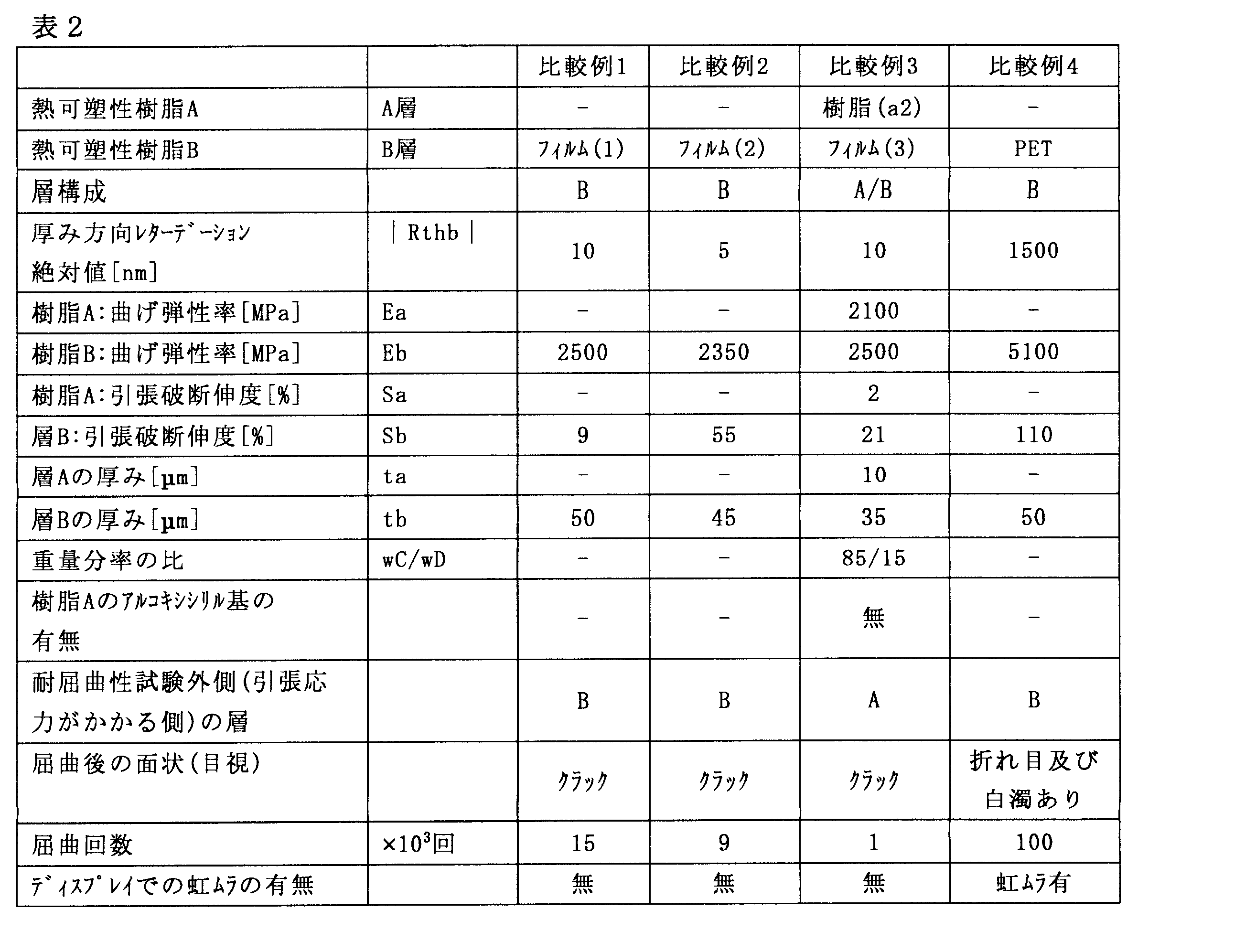
上記表中の用語は、下記の意味を表す。
a1:トリブロック共重合体水素化物(a1)
a1-s:トリブロック共重合体水素化物のアルコキシシリル変性物(a1-s)
フィルム(1):シクロオレフィンポリマーフィルム(1)
フィルム(2):シクロオレフィンポリマーフィルム(2)
フィルム(3):シクロオレフィンポリマーフィルム(3)
PET:ポリエチレンテレフタレート
wC/wD:樹脂Aの原料であるブロック共重合体における、重量分率wCと重量分率wDとの比
Ea:樹脂Aからなる厚み4mmのフィルムについて測定された曲げ弾性率
Eb:B層を構成する樹脂Bからなる厚み4mmのフィルムについて測定された曲げ弾性率
Sa:樹脂Aからなる厚み1.5mmのフィルムについて測定された引張破断伸度
sb:層Bについて測定された引張破断伸度
a1:トリブロック共重合体水素化物(a1)
a1-s:トリブロック共重合体水素化物のアルコキシシリル変性物(a1-s)
フィルム(1):シクロオレフィンポリマーフィルム(1)
フィルム(2):シクロオレフィンポリマーフィルム(2)
フィルム(3):シクロオレフィンポリマーフィルム(3)
PET:ポリエチレンテレフタレート
wC/wD:樹脂Aの原料であるブロック共重合体における、重量分率wCと重量分率wDとの比
Ea:樹脂Aからなる厚み4mmのフィルムについて測定された曲げ弾性率
Eb:B層を構成する樹脂Bからなる厚み4mmのフィルムについて測定された曲げ弾性率
Sa:樹脂Aからなる厚み1.5mmのフィルムについて測定された引張破断伸度
sb:層Bについて測定された引張破断伸度
以上の結果によれば、A層が積層されておらずB層のみの比較例1、比較例2のフィルムは、実施例の光学積層フィルムと比較して、顕著に少ない屈曲回数でフィルムにクラックが発生することが分かる。また、厚み方向のレターデーションRthbが、式(1)を満たさない比較例4のフィルムは、ディスプレイパネルに装着した場合に虹ムラが観察され、また100×103回屈曲させた時点でフィルムに折れ目と白濁が観察されることが分かる。
また、引張破断伸度Saが、式(2)を満たさない比較例3の光学積層フィルムも、実施例の光学積層フィルムと比較して、顕著に少ない屈曲回数で、フィルムにクラックが発生することが分かる。
したがって、以上の結果は、本発明の光学積層フィルムの耐屈曲性が良好であることを示す。
また、引張破断伸度Saが、式(2)を満たさない比較例3の光学積層フィルムも、実施例の光学積層フィルムと比較して、顕著に少ない屈曲回数で、フィルムにクラックが発生することが分かる。
したがって、以上の結果は、本発明の光学積層フィルムの耐屈曲性が良好であることを示す。
101 A層
102 B層
302、303、602、603、702、703 導電性層
350、450、550、650、750 タッチパネル部材
100、200 光学積層フィルム
300、400、500、600、700 タッチパネル
102 B層
302、303、602、603、702、703 導電性層
350、450、550、650、750 タッチパネル部材
100、200 光学積層フィルム
300、400、500、600、700 タッチパネル
Claims (10)
- 熱可塑性樹脂[A]を含む少なくとも1つのA層及び熱可塑性樹脂[B]からなるB層を含み、
前記少なくとも1つのA層が、前記B層の少なくとも一方の面上に設けられており、
前記B層の厚み方向のレターデーションRthbが下式(1)を満たし、
前記熱可塑性樹脂[A]からなる厚み1.5mmのフィルム(a1)の引張破断伸度Saが、下記式(2)を満たす、光学積層フィルム。
(1)|Rthb|≦40nm
(2)Sa≧100% - 前記熱可塑性樹脂[A]からなる厚み4mmのフィルム(a2)の曲げ弾性率Eaが下記式(3)を満たし、
前記熱可塑性樹脂[B]からなる厚み4mmのフィルム(b)の曲げ弾性率Ebが、下記式(4)を満たす、請求項1に記載の光学積層フィルム。
(3)300MPa≦Ea≦900MPa
(4)2200MPa≦Eb≦2800MPa - 前記熱可塑性樹脂[A]が、ブロック共重合体水素化物[2]又は前記ブロック共重合体水素化物[2]のアルコキシシリル基変性物[3]を含み、
前記ブロック共重合体水素化物[2]は、ブロック共重合体[1]が水素化されて形成される構造を有する物質であり、
前記ブロック共重合体[1]は、芳香族ビニル化合物単位を含有する、前記ブロック共重合体[1]の1分子当たり2個以上の重合体ブロック[C]と、鎖状共役ジエン化合物単位を含有する、前記ブロック共重合体[1]1分子あたり1個以上の重合体ブロック[D]とを有し、前記ブロック共重合体[1]の全体に占める前記重合体ブロック[C]の重量分率wCと、前記ブロック共重合体[1]の全体に占める前記重合体ブロック[D]の重量分率wDとの比(wC/wD)が、30/70~60/40であり、
前記ブロック共重合体水素化物[2]は、前記ブロック共重合体[1]の主鎖及び側鎖の炭素-炭素不飽和結合及び芳香環の炭素-炭素不飽和結合が水素化されている物質である、請求項1又は2に記載の光学積層フィルム。 - 前記熱可塑性樹脂[A]が、前記ブロック共重合体水素化物[2]のアルコキシシリル基変性物[3]を含む、請求項3に記載の光学積層フィルム。
- 前記B層の引張破断伸度Sbが、下記式(5)を満たす、請求項1~4のいずれか1項に記載の光学積層フィルム。
(5)5%≦Sb≦60% - 前記熱可塑性樹脂[B]が、脂環式構造を含有する重合体を含む、請求項1~5のいずれか1項に記載の光学積層フィルム。
- 前記A層を2つ含み、前記B層の両面のそれぞれの上に、前記A層が設けられている、請求項1~6のいずれか1項に記載の光学積層フィルム。
- タッチセンサ部材と、画像表示素子とを含むタッチパネルであって、
前記タッチセンサ部材が、第1導電性層、請求項1~7のいずれか1項の光学積層フィルム、及び第2導電性層をこの順で含み、前記画像表示素子の視認側に設けられている、タッチパネル。 - タッチセンサ部材と、画像表示素子とを含むタッチパネルであって、
前記タッチセンサ部材が、第1導電性層、請求項1~6のいずれか1項の光学積層フィルム、及び第2導電性層をこの順で含み、前記画像表示素子の視認側に設けられており、
前記画像表示素子が、視認側の面を内側にして湾曲可能であり、
前記画像表示素子の前記視認側の面と、前記光学積層フィルムの前記A層側の面が対向するように前記タッチセンサ部材が配置されている、タッチパネル。 - タッチセンサ部材と、画像表示素子とを含むタッチパネルであって、
前記タッチセンサ部材が、第1導電性層、請求項1~6のいずれか1項の光学積層フィルム、及び第2導電性層をこの順で含み、前記画像表示素子の視認側に設けられており、
前記画像表示素子が、視認側の面を外側にして湾曲可能であり、
前記画像表示素子の前記視認側の面と、前記光学積層フィルムの前記B層側の面が対向するように前記タッチセンサ部材が配置されている、タッチパネル。
Priority Applications (4)
| Application Number | Priority Date | Filing Date | Title |
|---|---|---|---|
| US16/647,521 US11130848B2 (en) | 2017-09-27 | 2018-09-19 | Laminated optical film and touch panel |
| KR1020207008304A KR102514977B1 (ko) | 2017-09-27 | 2018-09-19 | 광학 적층 필름 및 터치 패널 |
| CN201880060053.9A CN111132828A (zh) | 2017-09-27 | 2018-09-19 | 光学层叠膜和触控面板 |
| JP2019545002A JP7264056B2 (ja) | 2017-09-27 | 2018-09-19 | 光学積層フィルム及びタッチパネル |
Applications Claiming Priority (2)
| Application Number | Priority Date | Filing Date | Title |
|---|---|---|---|
| JP2017187002 | 2017-09-27 | ||
| JP2017-187002 | 2017-09-27 |
Publications (1)
| Publication Number | Publication Date |
|---|---|
| WO2019065401A1 true WO2019065401A1 (ja) | 2019-04-04 |
Family
ID=65902969
Family Applications (1)
| Application Number | Title | Priority Date | Filing Date |
|---|---|---|---|
| PCT/JP2018/034620 Ceased WO2019065401A1 (ja) | 2017-09-27 | 2018-09-19 | 光学積層フィルム及びタッチパネル |
Country Status (6)
| Country | Link |
|---|---|
| US (1) | US11130848B2 (ja) |
| JP (1) | JP7264056B2 (ja) |
| KR (1) | KR102514977B1 (ja) |
| CN (1) | CN111132828A (ja) |
| TW (1) | TWI763925B (ja) |
| WO (1) | WO2019065401A1 (ja) |
Cited By (1)
| Publication number | Priority date | Publication date | Assignee | Title |
|---|---|---|---|---|
| WO2026058782A1 (ja) * | 2024-09-10 | 2026-03-19 | 東洋紡株式会社 | ポリエチレンテレフタレートフィルム、積層フィルム、及びフォルダブルディスプレイ |
Families Citing this family (2)
| Publication number | Priority date | Publication date | Assignee | Title |
|---|---|---|---|---|
| KR20210012896A (ko) * | 2019-07-26 | 2021-02-03 | 스미또모 가가꾸 가부시키가이샤 | 광학 적층체 및 이의 제조방법 |
| CN114023781B (zh) * | 2021-10-08 | 2023-06-16 | 业成科技(成都)有限公司 | 曲面电子装置及其制造方法 |
Citations (4)
| Publication number | Priority date | Publication date | Assignee | Title |
|---|---|---|---|---|
| WO2012043708A1 (ja) * | 2010-09-29 | 2012-04-05 | 日本ゼオン株式会社 | アルコキシシリル基を有するブロック共重合体水素化物及びその利用 |
| JP2014149508A (ja) * | 2013-02-04 | 2014-08-21 | Nippon Zeon Co Ltd | 積層位相差フィルム及び積層位相差フィルムの製造方法 |
| JP2017111567A (ja) * | 2015-12-15 | 2017-06-22 | コニカミノルタ株式会社 | タッチパネル装置 |
| JP2017165953A (ja) * | 2016-03-04 | 2017-09-21 | 東友ファインケム株式会社Dongwoo Fine−Chem Co., Ltd. | ハードコート組成物 |
Family Cites Families (18)
| Publication number | Priority date | Publication date | Assignee | Title |
|---|---|---|---|---|
| KR20020062817A (ko) | 2001-01-24 | 2002-07-31 | 스미또모 가가꾸 고오교오 가부시끼가이샤 | 아크릴계 수지 적층 필름 및 이것을 사용한 적층 성형품 |
| JP4003459B2 (ja) | 2001-01-24 | 2007-11-07 | 住友化学株式会社 | アクリル系樹脂積層フィルム及びそれを用いた積層成形品 |
| TWI422877B (zh) * | 2004-11-09 | 2014-01-11 | 日本傑恩股份有限公司 | Polarizing plate and liquid crystal display device |
| JP2009078359A (ja) * | 2007-09-25 | 2009-04-16 | Fujifilm Corp | 熱可塑性樹脂フィルムの製造方法 |
| WO2009133930A1 (ja) * | 2008-04-30 | 2009-11-05 | 旭化成イーマテリアルズ株式会社 | 樹脂組成物及びそれを用いたシート |
| CN102119190B (zh) * | 2008-08-12 | 2012-11-07 | 旭化成化学株式会社 | 氢化嵌段共聚物组合物和使用该组合物的成型体 |
| JP5807643B2 (ja) * | 2010-09-29 | 2015-11-10 | 日本ゼオン株式会社 | アルコキシシリル基を有するブロック共重合体水素化物及びその利用 |
| JP5900890B2 (ja) * | 2010-11-30 | 2016-04-06 | 日東電工株式会社 | タッチ入力機能を有する表示パネル装置 |
| US8842243B2 (en) * | 2011-02-01 | 2014-09-23 | Fujifilm Corporation | IPS or FFS-mode liquid-crystal display device |
| JP6295962B2 (ja) * | 2012-11-15 | 2018-03-20 | 日本ゼオン株式会社 | 樹脂組成物およびそれからなる成形体 |
| KR102114358B1 (ko) * | 2013-02-04 | 2020-05-22 | 니폰 제온 가부시키가이샤 | 적층 위상차 필름 및 그의 제조 방법 |
| JP2015055796A (ja) * | 2013-09-12 | 2015-03-23 | 富士フイルム株式会社 | 光学フィルム及び表示装置 |
| CN106061728A (zh) * | 2014-03-13 | 2016-10-26 | 日本瑞翁株式会社 | 复合多层片 |
| US20180043663A1 (en) | 2015-03-16 | 2018-02-15 | Zeon Corporation | Optical laminate, polarizing plate and liquid crystal display device |
| TWI700184B (zh) | 2015-03-25 | 2020-08-01 | 日商日本瑞翁股份有限公司 | 光學薄膜 |
| CN107428934B (zh) * | 2015-03-31 | 2020-10-02 | 旭化成株式会社 | 聚酰亚胺膜、聚酰亚胺清漆、使用了聚酰亚胺膜的制品、以及层积体 |
| JP6140774B2 (ja) * | 2015-07-22 | 2017-05-31 | 日東電工株式会社 | 透明な粘着剤層を有する偏光フィルム積層体及び表示パネル |
| CN105808006A (zh) * | 2016-03-24 | 2016-07-27 | 惠州Tcl移动通信有限公司 | 显示器件及其触摸屏 |
-
2018
- 2018-09-19 KR KR1020207008304A patent/KR102514977B1/ko active Active
- 2018-09-19 US US16/647,521 patent/US11130848B2/en active Active
- 2018-09-19 TW TW107132995A patent/TWI763925B/zh active
- 2018-09-19 JP JP2019545002A patent/JP7264056B2/ja active Active
- 2018-09-19 WO PCT/JP2018/034620 patent/WO2019065401A1/ja not_active Ceased
- 2018-09-19 CN CN201880060053.9A patent/CN111132828A/zh active Pending
Patent Citations (4)
| Publication number | Priority date | Publication date | Assignee | Title |
|---|---|---|---|---|
| WO2012043708A1 (ja) * | 2010-09-29 | 2012-04-05 | 日本ゼオン株式会社 | アルコキシシリル基を有するブロック共重合体水素化物及びその利用 |
| JP2014149508A (ja) * | 2013-02-04 | 2014-08-21 | Nippon Zeon Co Ltd | 積層位相差フィルム及び積層位相差フィルムの製造方法 |
| JP2017111567A (ja) * | 2015-12-15 | 2017-06-22 | コニカミノルタ株式会社 | タッチパネル装置 |
| JP2017165953A (ja) * | 2016-03-04 | 2017-09-21 | 東友ファインケム株式会社Dongwoo Fine−Chem Co., Ltd. | ハードコート組成物 |
Cited By (1)
| Publication number | Priority date | Publication date | Assignee | Title |
|---|---|---|---|---|
| WO2026058782A1 (ja) * | 2024-09-10 | 2026-03-19 | 東洋紡株式会社 | ポリエチレンテレフタレートフィルム、積層フィルム、及びフォルダブルディスプレイ |
Also Published As
| Publication number | Publication date |
|---|---|
| CN111132828A (zh) | 2020-05-08 |
| KR102514977B1 (ko) | 2023-03-27 |
| JPWO2019065401A1 (ja) | 2020-11-19 |
| TWI763925B (zh) | 2022-05-11 |
| US20200223995A1 (en) | 2020-07-16 |
| US11130848B2 (en) | 2021-09-28 |
| JP7264056B2 (ja) | 2023-04-25 |
| KR20200060378A (ko) | 2020-05-29 |
| TW201922493A (zh) | 2019-06-16 |
Similar Documents
| Publication | Publication Date | Title |
|---|---|---|
| JP6690635B2 (ja) | 光学フィルム | |
| KR102406582B1 (ko) | 편광판 보호 필름, 편광판 및 표시 장치 | |
| JP7264056B2 (ja) | 光学積層フィルム及びタッチパネル | |
| JP6777176B2 (ja) | 光学積層体及びその製造方法、偏光板及び表示装置 | |
| JP6557108B2 (ja) | 透明導電性フィルム及びタッチパネル | |
| TWI788510B (zh) | 堆疊薄膜及其製造方法以及偏光板 | |
| US20190011752A1 (en) | Optical laminate, polarizing plate, and liquid crystal display device | |
| JP7226333B2 (ja) | 偏光板保護フィルム、偏光板及び表示装置 | |
| JP2017065086A (ja) | 複層フィルム | |
| JP7279392B2 (ja) | 積層体 | |
| WO2018079563A1 (ja) | 積層フィルム、その製造方法、偏光板、及び表示装置 |
Legal Events
| Date | Code | Title | Description |
|---|---|---|---|
| 121 | Ep: the epo has been informed by wipo that ep was designated in this application |
Ref document number: 18863315 Country of ref document: EP Kind code of ref document: A1 |
|
| ENP | Entry into the national phase |
Ref document number: 2019545002 Country of ref document: JP Kind code of ref document: A |
|
| NENP | Non-entry into the national phase |
Ref country code: DE |
|
| 122 | Ep: pct application non-entry in european phase |
Ref document number: 18863315 Country of ref document: EP Kind code of ref document: A1 |