WO2019065052A1 - 携帯端末、携帯端末に実行させるプログラム、キャリブレーションシステム及びキャリブレーション方法 - Google Patents
携帯端末、携帯端末に実行させるプログラム、キャリブレーションシステム及びキャリブレーション方法 Download PDFInfo
- Publication number
- WO2019065052A1 WO2019065052A1 PCT/JP2018/031824 JP2018031824W WO2019065052A1 WO 2019065052 A1 WO2019065052 A1 WO 2019065052A1 JP 2018031824 W JP2018031824 W JP 2018031824W WO 2019065052 A1 WO2019065052 A1 WO 2019065052A1
- Authority
- WO
- WIPO (PCT)
- Prior art keywords
- vehicle
- acceleration
- acceleration sensor
- sudden braking
- portable terminal
- Prior art date
- Legal status (The legal status is an assumption and is not a legal conclusion. Google has not performed a legal analysis and makes no representation as to the accuracy of the status listed.)
- Ceased
Links
Images


Classifications
-
- B—PERFORMING OPERATIONS; TRANSPORTING
- B60—VEHICLES IN GENERAL
- B60W—CONJOINT CONTROL OF VEHICLE SUB-UNITS OF DIFFERENT TYPE OR DIFFERENT FUNCTION; CONTROL SYSTEMS SPECIALLY ADAPTED FOR HYBRID VEHICLES; ROAD VEHICLE DRIVE CONTROL SYSTEMS FOR PURPOSES NOT RELATED TO THE CONTROL OF A PARTICULAR SUB-UNIT
- B60W40/00—Estimation or calculation of non-directly measurable driving parameters for road vehicle drive control systems not related to the control of a particular sub unit, e.g. by using mathematical models
- B60W40/10—Estimation or calculation of non-directly measurable driving parameters for road vehicle drive control systems not related to the control of a particular sub unit, e.g. by using mathematical models related to vehicle motion
- B60W40/107—Longitudinal acceleration
-
- G—PHYSICS
- G01—MEASURING; TESTING
- G01P—MEASURING LINEAR OR ANGULAR SPEED, ACCELERATION, DECELERATION, OR SHOCK; INDICATING PRESENCE, ABSENCE, OR DIRECTION, OF MOVEMENT
- G01P13/00—Indicating or recording presence, absence, or direction, of movement
- G01P13/02—Indicating direction only, e.g. by weather vane
-
- G—PHYSICS
- G01—MEASURING; TESTING
- G01P—MEASURING LINEAR OR ANGULAR SPEED, ACCELERATION, DECELERATION, OR SHOCK; INDICATING PRESENCE, ABSENCE, OR DIRECTION, OF MOVEMENT
- G01P15/00—Measuring acceleration; Measuring deceleration; Measuring shock, i.e. sudden change of acceleration
-
- G—PHYSICS
- G01—MEASURING; TESTING
- G01P—MEASURING LINEAR OR ANGULAR SPEED, ACCELERATION, DECELERATION, OR SHOCK; INDICATING PRESENCE, ABSENCE, OR DIRECTION, OF MOVEMENT
- G01P15/00—Measuring acceleration; Measuring deceleration; Measuring shock, i.e. sudden change of acceleration
- G01P15/18—Measuring acceleration; Measuring deceleration; Measuring shock, i.e. sudden change of acceleration in two or more dimensions
-
- G—PHYSICS
- G01—MEASURING; TESTING
- G01P—MEASURING LINEAR OR ANGULAR SPEED, ACCELERATION, DECELERATION, OR SHOCK; INDICATING PRESENCE, ABSENCE, OR DIRECTION, OF MOVEMENT
- G01P21/00—Testing or calibrating of apparatus or devices covered by the preceding groups
Definitions
- the present invention relates to a portable terminal, a program executed by the portable terminal, a calibration system, and a calibration method.
- JP 1229931 S discloses a data storage device having a switch for controlling the operation of the data storage device, and a connector provided on the lower side of the step and connected to an external cord, and storing detected data.
- This data storage device is used for recording vehicle conditions such as acceleration.
- acceleration data is recorded in the data storage device described in JP 1229931 S, for example, as shown in FIG. 6, a dedicated acceleration sensor 61 is prepared, and this data is stored via the storage amplifier 62 and the A / D measuring device 63. It was connected to the storage device 64 and recorded.
- the present invention has been made in view of such technical problems, and an apparatus or method capable of detecting an acceleration along the traveling direction of the vehicle even if the acceleration sensor is not attached straight to the traveling direction of the vehicle Intended to provide.
- the portable terminal includes a three-axis acceleration sensor, a determination unit that determines an acceleration caused by a sudden braking of the vehicle detected by the three-axis acceleration sensor, and And a determination unit that determines the traveling direction of the vehicle based on the acceleration caused by the sudden braking of the vehicle when the resulting acceleration is determined.
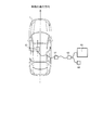
- FIG. 1 is a conceptual diagram showing a system of acceleration measurement using a portable terminal according to an embodiment of the present invention.
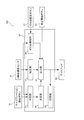
- FIG. 2 is a block diagram of a portable terminal according to an embodiment of the present invention.
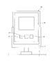
- FIG. 3 is a front view when the portable terminal according to the embodiment of the present invention is attached to a vehicle.
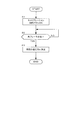
- FIG. 4 is a flowchart related to calibration according to an embodiment of the present invention.
- FIG. 5 is a flow chart related to acceleration measurement according to an embodiment of the present invention.
- FIG. 6 is a conceptual diagram showing a conventional acceleration measurement system.
- the system of acceleration measurement in the present embodiment fixes the portable terminal 100 to the vehicle 1 and uses the three-axis acceleration sensor 10 built in the portable terminal 100 to measure the acceleration caused by vibration or the like during traveling.
- the mobile terminal 100 includes a three-axis acceleration sensor 10, a display 20, and a control unit 30.
- the portable terminal 100 is a small terminal that can be carried by the user himself, and is, for example, a smartphone, a tablet type terminal, a small measuring instrument, a notebook computer, or the like.
- the portable terminal 100 is fixed to, for example, the dashboard 2 of the vehicle 1 via the holder 3 (see FIG. 3).
- the holder 3 may be a commercially available holder.
- the display 20 is configured of a touch panel display. By operating a button (see FIG. 3) displayed on the display 20, various programs can be executed.
- the portable terminal 100 detects the vibration during traveling of the vehicle 1 by the three-axis acceleration sensor 10, and displays the detection result on the display 20.
- a dedicated program (application) for detecting and displaying the vibration is installed in the portable terminal 100.
- the portable terminal 100 includes a central processing unit (CPU), a read only memory (ROM), a random access memory (RAM), a storage, and an input / output interface (I / O interface).
- CPU central processing unit
- ROM read only memory
- RAM random access memory
- storage a storage
- I / O interface input / output interface
- FIG. 2 is a block diagram of the portable terminal 100.
- the control unit 30 of the portable terminal 100 performs the road noise removal processing of the acceleration detected by the three-axis acceleration sensor 10, and the acceleration subjected to the road noise removal processing by the correction unit 31.
- the display unit 20 includes an output unit 32 that outputs data to the display 20 and the storage unit 33, and a zero point detection unit 34 that performs zero alignment of the three-axis acceleration sensor 10.
- the correction unit 31 calculates a simple moving average of the acceleration detected by the three-axis acceleration sensor 10. Thereby, when the vehicle 1 travels, it is possible to eliminate the influence of the change of the minute acceleration due to the unevenness of the road surface.
- the output unit 32 causes the display 20 to display the acceleration subjected to the road noise removal processing by the correction unit 31. Further, the output unit 32 stores the acceleration subjected to the road noise removal processing in the storage unit 33.
- the storage unit 33 may store time-series data from the start to the end of measurement and data of a predetermined period before and after the timing at which the trigger occurs.
- the trigger is configured to be automatically generated when a predetermined condition is satisfied, generated manually, or generated both automatically and manually.
- the zero point detection unit 34 performs the zero point alignment of the three-axis acceleration sensor 10 using the acceleration detected by the three-axis acceleration sensor 10. Specifically, the acceleration detected by the three-axis acceleration sensor 10 is set to 0 by pressing the zero point setting button 22 displayed on the display 20 when the vehicle 1 is stopped on a flat road. Gravitational acceleration acts on the three-axis acceleration sensor 10 downward. Since the mounting direction of the portable terminal 100 is not always the same, it is difficult to estimate in which direction the gravitational acceleration acts in advance. For this reason, by fixing the portable terminal 100 to the holder 3 and performing the zero point alignment, the influence of the gravitational acceleration can be eliminated regardless of the direction of the gravitational acceleration.
- the zero point setting button 22 is displayed on the display 20 together with a calibration start button 21 and a measurement start button 23 described later by activating the installed dedicated program (see FIG. 3).
- the possibility that one of the three axes (X axis, Y axis, Z axis) of the three-axis acceleration sensor 10 matches the traveling direction of the vehicle 1 is low.
- calibration for causing the mobile terminal 100 to recognize the traveling direction of the vehicle 1 is performed.
- the portable terminal 100 by causing the portable terminal 100 to recognize the traveling direction of the vehicle 1, the vector (coordinates) of the acceleration detected by the three-axis acceleration sensor 10 is converted into coordinates with the traveling direction of the vehicle 1 as a reference axis. It becomes possible.
- the calibration will be specifically described below.
- the control unit 30 determines the traveling direction of the vehicle 1 based on the determination unit 35 that determines the acceleration caused by the sudden braking of the vehicle 1 detected by the three-axis acceleration sensor 10 and the acceleration caused by the sudden braking of the vehicle 1 And a determination unit 36.
- the determination unit 35 determines that the sudden braking has occurred.
- the determination unit 35 determines that the acceleration caused by the sudden braking of the vehicle 1 is generated by the determination unit 35, the determination unit 36 determines the direction in which the acceleration is generated as the traveling direction of the vehicle 1.
- the portable terminal 100 is fixed to the vehicle 1 via the holder 3 and a dedicated program installed in the portable terminal 100 is activated.
- the calibration start button 21, the zero point setting button 22, the measurement start button 23 and the like are displayed on the display 20 (see FIG. 3).
- step S1 calibration is started. Specifically, the determination unit 35 determines that the trigger is selected by pressing the calibration start button 21 and starts the calibration.
- step S2 it is determined whether sudden braking has occurred. Specifically, the driver advances the vehicle 1 and applies the sudden brake. At this time, the determination unit 35 determines whether the magnitude of the acceleration generated in the direction opposite to the traveling direction of the vehicle 1 is equal to or more than a predetermined value. If it is determined by the determination unit 35 that the magnitude of the acceleration is equal to or greater than the predetermined value (sudden braking has occurred), the process proceeds to step S3 and the magnitude of the acceleration is less than the predetermined value by the determination unit 35 (sudden braking occurs If it is not determined, the determination in step S2 is repeated.
- the predetermined value used for the determination can be obtained in advance by experiment or the like according to the sensitivity of the three-axis acceleration sensor 10 to be used. In addition, when sudden braking does not occur within predetermined time, it will time out.
- the traveling direction of the vehicle 1 is determined by generating a sudden brake.
- the method of determining by change of the acceleration by accelerator ON is also considered.
- the absolute value of the acceleration is small, it is difficult to distinguish between the acceleration in the traveling direction and the gravitational acceleration, or an error based on the gravitational acceleration, and the accuracy in determining the traveling direction is lowered. Therefore, the determination accuracy of the traveling direction can be improved by performing the determination based on the sudden braking in which the absolute value of the acceleration becomes large.
- the calibration method of the present embodiment is preferable in that the traveling direction can be determined only by the three-axis acceleration sensor 10.
- step S3 the traveling direction of the vehicle 1 is determined. Specifically, based on the acceleration caused by the sudden braking (the acceleration when it is determined by the determination unit 35 that the sudden braking has occurred), the determination unit 36 determines the direction opposite to the direction in which the acceleration is generated. Determine the direction of travel. Then, the determination unit 36 transmits, to the output unit 32, information regarding the determined traveling direction of the vehicle 1.
- the output unit 32 stores information on the determined traveling direction of the vehicle 1 and notifies on the display 20 that the calibration is completed.
- step S11 By pressing the measurement start button 23 displayed on the display 20 (step S11), measurement of acceleration is started.
- the acceleration detected by the three-axis acceleration sensor 10 is input to the correction unit 31 as described above.
- the correction unit 31 performs road noise removal processing of the acceleration detected by the three-axis acceleration sensor 10 (step S12). Specifically, a simple moving average of the acceleration detected by the three-axis acceleration sensor 10 is calculated. The data of the simple moving average of the calculated acceleration is input to the output unit 32.
- step S13 coordinate conversion is performed. Specifically, the output unit 32 sets the coordinates of the acceleration vector input from the correction unit 31 to the traveling direction of the vehicle 1 determined by the determination unit 36 from the coordinates of the three axes of the three-axis acceleration sensor 10. Convert to coordinates with two reference axes.
- the output unit 32 causes the display 20 to display the magnitude of the acceleration in the traveling direction of the vehicle 1 based on the converted coordinate data of the vector (step S14).
- the output unit 32 stores, in the storage unit 33, data (time-series data) of the acceleration in the traveling direction of the vehicle 1.
- the portable terminal 100 after road noise removal processing is performed on the acceleration detected by the three-axis acceleration sensor 10, coordinate conversion is performed on three axes with the traveling direction of the vehicle 1 as one axis. Thereby, regardless of the direction in which the portable terminal 100 is fixed with respect to the traveling direction of the vehicle 1, the acceleration in the traveling direction of the vehicle 1 can be displayed.
- the acceleration sensor 61 dedicated to the vehicle 1 is attached straight to the traveling direction of the vehicle 1 and firmly fixed using an adhesive. Further, after the measurement, the adhesive was dissolved with a solvent and the acceleration sensor 61 was removed.
- the portable terminal 100 by using the holder 3, it can be easily fixed to or removed from the vehicle 1.
- the acceleration sensor 61 is connected to the storage amplifier 62 and the A / D measuring device 63, data is stored in the data storage device 64, and the measurement result is displayed on the display 65. For this reason, the equipment became large-scaled, and it was not able to measure easily.
- the portable terminal 100 incorporates the three-axis acceleration sensor 10, the equipment does not need to be large-scaled, and the wiring operation can be made unnecessary.
- the portable terminal 100 since the portable terminal 100 includes the display 20, it is not necessary to separately prepare a display.
- the portable terminal 100 by performing the calibration as described above, the acceleration in the traveling direction of the vehicle 1 can be obtained regardless of the direction in which the portable terminal 100 is attached with respect to the traveling direction of the vehicle 1. It can be detected. That is, by using the portable terminal 100, it is possible to eliminate the work of attaching straightly and the work of zeroing, thus simplifying the work.
- the process related to the determination unit 35 and the determination unit 36 is performed in the portable terminal 100.
- the process related to the determination unit 35 and the determination unit 36 is not limited to this. You may make it run.
- the storage unit 33 is provided in the portable terminal 100.
- the storage unit 33 may be an external storage medium or a storage medium that can be attached to and detached from the portable terminal 100, such as an SD card.
- the portable terminal 100 demonstrated the thing provided with the display 20 to the example in this embodiment, the display 20 does not necessarily need to be provided.
- a separate display may be provided to display measurement results and the like on the display.
- the portable terminal 100 is caused by the three-axis acceleration sensor 10, a determination unit 35 that determines the acceleration caused by the sudden braking of the vehicle 1 detected by the three-axis acceleration sensor 10, and the determination unit 35 And a determination unit configured to determine the traveling direction of the vehicle based on the acceleration caused by the sudden braking of the vehicle when the acceleration is determined.
- the three-axis acceleration sensor 10 even if the three-axis acceleration sensor 10 is not attached straight to the traveling direction of the vehicle 1, the acceleration along the traveling direction of the vehicle 1 can be detected. Thereby, the attachment work of the acceleration sensor can be simplified. Moreover, by using the portable terminal 100 provided with the three-axis acceleration sensor 10, the equipment does not become large-scaled, and the wiring operation can be made unnecessary.
- the portable terminal 100 has a display 20.
- the measurement result can be referred to by the portable terminal 100, and there is no need to prepare a separate display.
- the display 20 is a touch panel display, and the determination unit 35 determines the traveling direction of the vehicle 1 after the trigger displayed on the display 20 is selected (the calibration start button 21 is pressed). Start.
- a driver using this system tries to place the portable terminal 100 at a position where the display 20 of the portable terminal 100 can be easily viewed. Therefore, since the display 20 is a touch panel display, the button displayed on the display 20 naturally comes to a position facing the driver, which facilitates the operation.
- the portable terminal 100 has a zero point detection unit 34 that performs zero alignment of the three-axis acceleration sensor 10 using the acceleration detected by the three-axis acceleration sensor 10 when the vehicle 1 is stopped on a flat road.
- the effect of gravity can be eliminated by zeroing while stopped and on a flat road (not a slope).
- the mobile terminal 100 includes a correction unit 31 that calculates a simple moving average of the acceleration detected by the three-axis acceleration sensor 10 and performs road noise removal processing.
- the acceleration can be detected accurately.
- the determination unit 35 that determines the acceleration caused by the sudden braking of the vehicle 1 detected by the three-axis acceleration sensor 10 and the acceleration caused by the sudden braking of the vehicle 1 by the determination unit 35
- a determination unit 36 that determines the traveling direction of the vehicle 1 based on the acceleration caused by the sudden braking of the vehicle 1 when it is determined that
- the processing related to the determination unit 35 and the determination unit 36 can be executed by an external device to perform calibration of the three-axis acceleration sensor 10 of the portable terminal 100.
- the program installed in the portable terminal 100 includes a first process of determining the acceleration caused by the sudden braking of the vehicle 1 detected by the three-axis acceleration sensor 10 and an acceleration caused by the sudden braking of the vehicle 1 in the first process.
- the control unit 30 of the portable terminal 100 is caused to execute a second process of determining the traveling direction of the vehicle 1 based on the acceleration caused by the sudden braking of the vehicle 1.
- the vehicle 1 is moved forward to generate a sudden brake, but the vehicle 1 may be moved backward to generate a sudden brake.
- Zeroing may be performed prior to performing the calibration.
Landscapes
- Physics & Mathematics (AREA)
- General Physics & Mathematics (AREA)
- Engineering & Computer Science (AREA)
- Automation & Control Theory (AREA)
- Mathematical Physics (AREA)
- Transportation (AREA)
- Mechanical Engineering (AREA)
- Indicating Or Recording The Presence, Absence, Or Direction Of Movement (AREA)
- Control Of Driving Devices And Active Controlling Of Vehicle (AREA)
- Telephone Function (AREA)
Abstract
携帯端末は、3軸加速度センサと、3軸加速度センサにより検知された車両の急ブレーキに起因する加速度を判定する判定部と、判定部によって車両の急ブレーキに起因する加速度が判定された場合に、車両の急ブレーキに起因する加速度に基づき車両の進行方向を決定する決定部と、を有する。
Description
本発明は、携帯端末、携帯端末に実行させるプログラム、キャリブレーションシステム及びキャリブレーション方法に関する。
JP1229931Sには、データ記憶装置の作動を制御するスイッチと、段部下側に設置され外部コードと接続するコネクタと、を有し、検出されたデータを記憶するデータ記憶装置が開示されている。このデータ記憶装置は、加速度等の車両状態を記録する用途に利用される。
加速度データをJP1229931Sに記載されたデータ記憶装置に記録する場合は、例えば、図6に示すように、専用の加速度センサ61を用意し、ストレージアンプ62及びA/D計測器63を介して本データ記憶装置64と接続して記録していた。
この場合、車両に加速度センサ61を車両の進行方向に対してまっすぐ取り付け、接着剤を用いて強固に固定する必要がある。このため、車両内では、取り付けることができる場所が限られてしまう。また、車両進行方向へ向かうようにまっすぐと取り付けるためには、作業の習熟度が要求されるとともに、作業が煩雑になる。
本発明は、このような技術的課題に鑑みてなされたもので、加速度センサを車両の進行方向に対してまっすぐに取り付けていなくても、車両の進行方向に沿った加速度を検出できる装置または方法を提供することを目的とする。
本発明のある態様によれば、携帯端末は、3軸加速度センサと、3軸加速度センサにより検知された車両の急ブレーキに起因する加速度を判定する判定部と、判定部によって車両の急ブレーキに起因する加速度が判定された場合に、車両の急ブレーキに起因する加速度に基づき車両の進行方向を決定する決定部と、を有する。
この態様によれば、加速度センサを車両の進行方向に対してまっすぐに取り付けていなくても、車両の進行方向に沿った加速度を検出できる。
以下、添付図面を参照しながら本発明の実施形態について説明する。
本実施形態における加速度測定のシステムは、車両1に携帯端末100を固定し、携帯端末100に内蔵された3軸加速度センサ10を用いて、走行中の振動などによって生じる加速度を測定する。
携帯端末100は、3軸加速度センサ10と、ディスプレイ20と、制御部30と、を備える。携帯端末100は、使用者自身で持ち運び可能な小型端末であり、例えば、スマートフォン、タブレット型端末、小型の測定器、ノートパソコン等である。携帯端末100は、例えば、車両1のダッシュボード2に保持具3(図3参照)を介して固定される。保持具3は、市販されている保持具でよい。
ディスプレイ20は、タッチパネル式ディスプレイによって構成される。ディスプレイ20上に表示されたボタン(図3参照)を操作することにより、各種プログラムを実行できる。
携帯端末100は、車両1の走行時の振動を3軸加速度センサ10によって検出し、その検出結果をディスプレイ20に表示する。携帯端末100には、振動を検出及び表示するための専用のプログラム(アプリケーション)がインストールされる。
携帯端末100は、中央演算装置(CPU)、読み出し専用メモリ(ROM)、ランダムアクセスメモリ(RAM)、ストレージ及び入出力インタフェース(I/Oインタフェース)を備える。なお、後述する制御部30における判定部35、決定部36及び補正部31といったユニットは、携帯端末100において実行されるプログラムの機能を仮想的なユニットとしたものである。
図2は、携帯端末100のブロック図である。図2に示すように、携帯端末100の制御部30は、3軸加速度センサ10により検知された加速度のロードノイズ除去処理を行う補正部31と、補正部31によってロードノイズ除去処理された加速度をディスプレイ20及び記憶部33に出力する出力部32と、3軸加速度センサ10のゼロ点合わせを行うゼロ点検知部34と、を備える。
補正部31は、3軸加速度センサ10により検知された加速度の単純移動平均を演算する。これにより、車両1の走行時において、路面の凹凸による微小な加速度の変化による影響を排除することができる。
出力部32は、補正部31によってロードノイズ除去処理された加速度をディスプレイ20に表示させる。また、出力部32は、ロードノイズ除去処理された加速度を記憶部33に保存する。なお、記憶部33には、測定開始から終了までの時系列データと、トリガが発生したタイミングの前後の所定期間のデータと、を保存するようにしてもよい。この場合、トリガが、あらかじめ定められた条件を満たしたときに自動で発生する、手動で発生する、あるいは、自動及び手動の両方によって発生するように構成される。
ゼロ点検知部34は、3軸加速度センサ10により検知された加速度を用いて、3軸加速度センサ10のゼロ点合わせを行う。具体的には、車両1が平坦路で停車しているときにディスプレイ20に表示されたゼロ点設定ボタン22を押すことにより、3軸加速度センサ10により検知された加速度を0にする。3軸加速度センサ10には、下方に重力加速度が作用する。携帯端末100の取り付け方向が常に同じとは限らないため、どの方向に重力加速度が作用するかを予め想定することは難しい。このため、携帯端末100を保持具3に固定した後にゼロ点合わせを行うことにより、どのような方向に重力加速度が作用していても、重力加速度による影響を排除することができる。なお、ゼロ点設定ボタン22は、インストールされた専用のプログラムを起動することにより、後述するキャリブレーション開始ボタン21及び測定開始ボタン23とともにディスプレイ20上に表示される(図3参照)。
携帯端末100を保持具3に固定したとき、3軸加速度センサ10の3軸(X軸、Y軸、Z軸)のいずれかが、車両1の進行方向に一致している可能性は低い。言い換えると、3軸加速度センサ10の3軸が、車両1の進行方向に対してずれている可能性が高い。このため、携帯端末100では、携帯端末100を保持具3に固定した後、携帯端末100に車両1の進行方向を認識させるためのキャリブレーションを行う。このように、携帯端末100に車両1の進行方向を認識させることで、3軸加速度センサ10によって検出された加速度のベクトル(座標)を、車両1の進行方向を基準軸とした座標に変換することが可能になる。以下、キャリブレーションについて具体的に説明する。
制御部30は、3軸加速度センサ10により検知された車両1の急ブレーキに起因する加速度を判定する判定部35と、車両1の急ブレーキに起因する加速度に基づき車両1の進行方向を決定する決定部36と、をさらに備える。
判定部35は、3軸加速度センサ10により検知された加速度の大きさが所定値以上の場合に、急ブレーキが発生したと判定する。また、決定部36は、判定部35によって車両1の急ブレーキに起因する加速度が発生したと判定された場合に、その加速度が生じた方向を車両1の進行方向と決定する。
次に、図4に示すフローチャートを参照しながら、キャリブレーションの具体的な手順について説明する。
まず、準備段階として、携帯端末100を保持具3を介して車両1に固定し、携帯端末100にインストールされた専用のプログラムを起動する。プログラムが起動すると、ディスプレイ20にキャリブレーション開始ボタン21、ゼロ点設定ボタン22、及び測定開始ボタン23などが表示される(図3参照)。
そして、キャリブレーション開始ボタン21を押す(ステップS1)ことによって、キャリブレーションが開始される。具体的には、判定部35は、キャリブレーション開始ボタン21が押されることによってトリガが選択されたと判定し、キャリブレーションを開始する。
ステップS2では、急ブレーキが発生したか否かを判定する。具体的には、ドライバが車両1を前進させ、急ブレーキを踏む。このとき、判定部35は、車両1の進行方向と反対方向に発生する加速度の大きさが所定値以上であるか否かを判定する。判定部35によって加速度の大きさが所定値以上である(急ブレーキが発生した)と判定されれば、ステップS3進み、判定部35によって加速度の大きさが所定値未満である(急ブレーキが発生していない)と判定されれば、ステップS2による判定を繰り返す。判定に用いられる所定値は、使用する3軸加速度センサ10の感度に応じて予め実験等で予め求めておくことができる。なお、所定時間内に急ブレーキが発生しなかった場合には、タイムアウトになる。
本実施形態では、急ブレーキを発生させるによって車両1の進行方向を決定している。これに対し、アクセルONによる加速度の変化によって決定する方法も考えられる。しかしながら、エンジン出力の小さい車などでは、大きな加速度の変化を作り出すことが難しい。また、加速度の絶対値が小さいと、進行方向における加速度と重力加速度、あるいは重力加速度に基づく誤差等との判別が難しく、進行方向の決定精度が低下する。よって、加速度の絶対値が大きくなる急ブレーキに基づいて判定を行うことにより、進行方向の決定精度を向上させることができる。
また、車両旋回時の遠心力から進行方向を決定する方法も考えられる。しかしながら、旋回の度合いや車速などを別のセンサを用いて取得する必要がある。よって、本実施形態のキャリブレーション方法が、3軸加速度センサ10のみで進行方向を決定できる点で好適である。
ステップS3では、車両1の進行方向を決定する。具体的には、決定部36は、急ブレーキに起因する加速度(判定部35によって急ブレーキが発生したと判定されたときの加速度)に基づいて、加速度が発生した方向と反対方向を車両1の進行方向と決定する。そして、決定部36は、決定した車両1の進行方向に関する情報を出力部32に送信する。
出力部32は、決定した車両1の進行方向に関する情報を記憶するとともに、ディスプレイ20上にキャリブレーションが終了したことを告知する。
このようにしてキャリブレーションが終了した後、加速度の測定を開始する。続いて、加速度の測定について、図5に示すフローチャートを参照しながら説明する。
ディスプレイ20に表示された測定開始ボタン23を押すこと(ステップS11)によって、加速度の測定が開始される。
3軸加速度センサ10によって検出された加速度は、上述のように、補正部31に入力される。補正部31では、3軸加速度センサ10によって検出された加速度のロードノイズ除去処理を行う(ステップS12)。具体的には、3軸加速度センサ10によって検出された加速度の単純移動平均を演算する。演算された加速度の単純移動平均のデータは、出力部32に入力される。
ステップS13では、座標変換を行う。具体的には、出力部32は、補正部31から入力された加速度のベクトルの座標を、3軸加速度センサ10の3軸における座標から、決定部36によって決定された車両1の進行方向を1つの基準軸とした座標に変換する。
その後、出力部32は、変換したベクトルの座標データに基づいて、車両1の進行方向における加速度の大きさをディスプレイ20に表示させる(ステップS14)。また、これと同時に、出力部32は、車両1の進行方向における加速度のデータ(時系列データ)を記憶部33に保存する。
このように、携帯端末100では、3軸加速度センサ10によって検出された加速度にロードノイズ除去処理を施した後、車両1の進行方向を1つの軸とした3軸に座標変換する。これにより、携帯端末100が車両1の進行方向に対してどのような向きに固定されていても、車両1の進行方向における加速度を表示することができる。
図6に示す従来例では、車両1に専用の加速度センサ61を車両1の進行方向に対してまっすぐに取り付け、接着剤を用いて強固に固定していた。また、測定後は、溶剤で接着剤を溶かして加速度センサ61を取り外していた。
これに対し、携帯端末100では、保持具3を用いることにより車両1に対して簡単に固定または取り外すことができる。
また、図6に示す従来例では、加速度センサ61にストレージアンプ62及びA/D計測器63と接続し、データ記憶装置64にデータを記憶させるとともに、測定結果をディスプレイ65に表示していた。このため、機材が大掛かりとなり、手軽に測定をすることができなかった。
これに対し、携帯端末100は3軸加速度センサ10を内蔵しているので、機材が大掛かりとならず、配線作業も不要にすることができる。また、携帯端末100がディスプレイ20を備えることにより、別途ディスプレイを用意する必要がない。
さらに、図6に示す従来例では、加速度センサ61を車両1の進行方向へ向かうようにまっすぐに取り付ける必要があるため、車両1内で取り付けできる場所が限られるとともに、作業の習熟度が要求される。さらに、測定の際のゼロ点合わせはストレージアンプ62を用いて行うため、作業が煩雑になる。
これに対し、携帯端末100では、上述のようなキャリブレーションを行うことにより、携帯端末100が車両1の進行方向に対してどのような向きに取り付けられても、車両1の進行方向における加速度を検出することができる。つまり、携帯端末100を用いることにより、まっすぐに取り付けるといった作業やゼロ点合わせの作業を不要にすることができるので、作業が簡単になる。
なお、上記実施形態では、判定部35及び決定部36等に関する処理は、携帯端末100内で実行されていたが、これに限らず、判定部35及び決定部36等に関する処理を外部の装置において実行させるようにしてもよい。また、上記実施形態では、記憶部33を携帯端末100内に設けていたが、記憶部33は、外部の記憶媒体や、SDカードなど携帯端末100に着脱可能な記憶媒体であってもよい。
また、本実施形態では、携帯端末100がディスプレイ20を備えているものを例に説明したが、ディスプレイ20は必ずしも備えていなくてもよい。また、別途ディスプレイを設け、測定結果等をこのディスプレイに表示するようにしてもよい。
以上のように構成された本発明の実施形態の構成、作用、及び効果をまとめて説明する。
携帯端末100は、3軸加速度センサ10と、3軸加速度センサ10により検知された車両1の急ブレーキに起因する加速度を判定する判定部35と、判定部35によって車両1の急ブレーキに起因する加速度が判定された場合に、車両1の急ブレーキに起因する加速度に基づき車両1の進行方向を決定する決定部36と、を有する。
この構成によれば、3軸加速度センサ10を車両1の進行方向に対してまっすぐに取り付けていなくても、車両1の進行方向に沿った加速度を検出できる。これにより、加速度センサの取り付け作業を簡素化できる。また、3軸加速度センサ10を備えた携帯端末100を用いることにより、機材が大掛かりとならず、配線作業も不要にすることができる。
携帯端末100は、ディスプレイ20を有する。
ディスプレイ20を有することにより、測定結果を携帯端末100で参照することができ、別途ディスプレイを用意する必要がなくなる。
携帯端末100では、ディスプレイ20はタッチパネル式ディスプレイであり、判定部35は、ディスプレイ20に表示したトリガが選択された(キャリブレーション開始ボタン21が押された)後に、車両1の進行方向の判定を開始する。
本システムを利用するドライバは携帯端末100のディスプレイ20が見やすい位置に携帯端末100を配置しようとする。このため、ディスプレイ20がタッチパネル式ディスプレイであることによって、ディスプレイ20上に表示されたボタンも自然とドライバと対向する位置になるので、操作がしやすくなる。
携帯端末100は、車両1が平坦路で停車しているときの3軸加速度センサ10により検知された加速度を用いて、3軸加速度センサ10のゼロ点合わせを行うゼロ点検知部34を有する。
停車中且つ平坦路(坂道ではないところ)でゼロ点合わせを行うことにより、重力の影響を排除することができる。
携帯端末100は、3軸加速度センサ10により検知された加速度の単純移動平均を演算してロードノイズ除去処理を行う補正部31を有する。
ロードノイズ除去処理を行うことにより、精度よく加速度を検出できる。
また、本実施形態におけるキャリブレーションシステムは、3軸加速度センサ10により検知された車両1の急ブレーキに起因する加速度を判定する判定部35と、判定部35によって車両1の急ブレーキに起因する加速度が発生したと判定された場合に、車両1の急ブレーキに起因する加速度に基づき車両1の進行方向を決定する決定部36と、を有する。
この構成では、例えば、判定部35及び決定部36に関する処理を外部の装置において実行させて、携帯端末100の3軸加速度センサ10のキャリブレーションを実行することができる。
携帯端末100にインストールされたプログラムは、3軸加速度センサ10により検知された車両1の急ブレーキに起因する加速度を判定する第1処理と、第1処理において車両1の急ブレーキに起因する加速度が発生したと判定された場合に、車両1の急ブレーキに起因する加速度に基づき車両1の進行方向を決定する第2処理と、を携帯端末100の制御部30に実行させる。
このプログラムを携帯端末100にインストールして実行することにより、3軸加速度センサ10を車両1の進行方向に対してまっすぐに取り付けていなくても、車両1の進行方向に沿った加速度を検出できる。
以上、本発明の実施形態について説明したが、上記実施形態は本発明の適用例の一部を示したものに過ぎず、本発明の技術的範囲を上記実施形態の具体的構成に限定する趣旨ではない。
なお、上記実施形態では、車両1を前進させて急ブレーキを発生させていたが、車両1を後進させて急ブレーキを発生させるようにしてもよい。
ゼロ点合わせは、キャリブレーションを行う前に実行してもよい。
本願は、2017年9月26日に日本国特許庁に出願された特願2017-185190号に基づく優先権を主張し、この出願の全ての内容は参照により本明細書に組み込まれる。
Claims (8)
- 携帯端末であって、
3軸加速度センサと、
前記3軸加速度センサにより検知された車両の急ブレーキに起因する加速度を判定する判定部と、
前記判定部によって前記車両の急ブレーキに起因する加速度が発生したと判定された場合に、前記車両の急ブレーキに起因する加速度に基づき前記車両の進行方向を決定する決定部と、を有する携帯端末。 - 請求項1に記載された携帯端末において、
前記携帯端末は、ディスプレイを有する携帯端末。 - 請求項2に記載された携帯端末において、
前記ディスプレイはタッチパネル式ディスプレイであり、
前記判定部は、前記ディスプレイに表示したトリガが選択された後に、前記車両の進行方向の判定を開始する携帯端末。 - 請求項1乃至請求項3のいずれか1つに記載された携帯端末において、
前記携帯端末は、前記車両が平坦路で停車しているときの前記3軸加速度センサにより検知された加速度を用いて、前記3軸加速度センサのゼロ点合わせを行うゼロ点検知部を有する携帯端末。 - 請求項1乃至請求項4のいずれか1つに記載された携帯端末において、
前記携帯端末は、前記3軸加速度センサにより検知された加速度の単純移動平均を演算してロードノイズ除去処理を行う補正部を有する携帯端末。 - 車両に搭載される携帯端末に設けられた3軸加速度センサのキャリブレーションを行うキャリブレーションシステムであって、
前記3軸加速度センサにより検知された前記車両の急ブレーキに起因する加速度を判定する判定部と、
前記判定部によって前記車両の急ブレーキに起因する加速度が発生したと判定された場合に、前記車両の急ブレーキに起因する加速度に基づき前記車両の進行方向を決定する決定部と、を有するキャリブレーションシステム。 - 3軸加速度センサを備えた携帯端末に実行させるプログラムであって、
前記3軸加速度センサにより検知された車両の急ブレーキに起因する加速度を判定する第1処理と、
前記第1処理において前記車両の急ブレーキに起因する加速度が発生したと判定された場合に、前記車両の急ブレーキに起因する加速度に基づき前記車両の進行方向を決定する第2処理と、を前記携帯端末に実行させるプログラム。 - 車両に搭載される携帯端末に設けられた3軸加速度センサのキャリブレーション方法であって、
前記3軸加速度センサにより検知された前記車両の急ブレーキに起因する加速度を判定する工程と、
前記判定する工程において前記車両の急ブレーキに起因する加速度が発生したと判定された場合に、前記車両の急ブレーキに起因する加速度に基づき前記車両の進行方向を決定する工程と、を有するキャリブレーション方法。
Priority Applications (1)
| Application Number | Priority Date | Filing Date | Title |
|---|---|---|---|
| JP2019544449A JP6684393B2 (ja) | 2017-09-26 | 2018-08-28 | 携帯端末、携帯端末に実行させるプログラム、キャリブレーションシステム及びキャリブレーション方法 |
Applications Claiming Priority (2)
| Application Number | Priority Date | Filing Date | Title |
|---|---|---|---|
| JP2017-185190 | 2017-09-26 | ||
| JP2017185190 | 2017-09-26 |
Publications (1)
| Publication Number | Publication Date |
|---|---|
| WO2019065052A1 true WO2019065052A1 (ja) | 2019-04-04 |
Family
ID=65903680
Family Applications (1)
| Application Number | Title | Priority Date | Filing Date |
|---|---|---|---|
| PCT/JP2018/031824 Ceased WO2019065052A1 (ja) | 2017-09-26 | 2018-08-28 | 携帯端末、携帯端末に実行させるプログラム、キャリブレーションシステム及びキャリブレーション方法 |
Country Status (2)
| Country | Link |
|---|---|
| JP (1) | JP6684393B2 (ja) |
| WO (1) | WO2019065052A1 (ja) |
Families Citing this family (1)
| Publication number | Priority date | Publication date | Assignee | Title |
|---|---|---|---|---|
| JP6808534B2 (ja) * | 2017-02-22 | 2021-01-06 | パーク二四株式会社 | 加速度センサオートアライメント装置およびコンピュータプログラム |
Citations (2)
| Publication number | Priority date | Publication date | Assignee | Title |
|---|---|---|---|---|
| JP5990553B2 (ja) * | 2014-04-22 | 2016-09-14 | 株式会社日立製作所 | 携帯端末用プログラム、携帯端末、自動車運転特性診断システム、自動車加速度算出方法 |
| JP6190423B2 (ja) * | 2015-06-30 | 2017-08-30 | ヤフー株式会社 | 推定装置、移動方向推定方法及び移動方向推定プログラム |
Family Cites Families (3)
| Publication number | Priority date | Publication date | Assignee | Title |
|---|---|---|---|---|
| JP6393537B2 (ja) * | 2014-07-09 | 2018-09-19 | 株式会社デンソーテン | 車両用装置、車両制御システム、車両制御方法 |
| JP2016057836A (ja) * | 2014-09-09 | 2016-04-21 | 株式会社日立製作所 | 移動体分析システムおよび移動体の方向軸推定方法 |
| JP6535606B2 (ja) * | 2016-01-14 | 2019-06-26 | 株式会社日立製作所 | 携帯端末用プログラム、携帯端末、情報通信システム、車両加速度算出方法 |
-
2018
- 2018-08-28 WO PCT/JP2018/031824 patent/WO2019065052A1/ja not_active Ceased
- 2018-08-28 JP JP2019544449A patent/JP6684393B2/ja active Active
Patent Citations (2)
| Publication number | Priority date | Publication date | Assignee | Title |
|---|---|---|---|---|
| JP5990553B2 (ja) * | 2014-04-22 | 2016-09-14 | 株式会社日立製作所 | 携帯端末用プログラム、携帯端末、自動車運転特性診断システム、自動車加速度算出方法 |
| JP6190423B2 (ja) * | 2015-06-30 | 2017-08-30 | ヤフー株式会社 | 推定装置、移動方向推定方法及び移動方向推定プログラム |
Also Published As
| Publication number | Publication date |
|---|---|
| JP6684393B2 (ja) | 2020-04-22 |
| JPWO2019065052A1 (ja) | 2020-04-02 |
Similar Documents
| Publication | Publication Date | Title |
|---|---|---|
| US20160356675A1 (en) | Motion detection devices and systems | |
| US9448250B2 (en) | Detecting mount angle of mobile device in vehicle using motion sensors | |
| JP2008002992A (ja) | 姿勢角検出装置と姿勢角検出方法 | |
| US9599633B2 (en) | Mounting angle calibration for an in-vehicle accelerometer device | |
| US20220189221A1 (en) | Information recording device, information recording method, and program for recording information | |
| CN103837302A (zh) | 一种风扇剩余动不平衡量检测装置及方法 | |
| JP5625557B2 (ja) | 停止判定方法 | |
| US11112861B2 (en) | Determination of a spatial orientation | |
| JP6684393B2 (ja) | 携帯端末、携帯端末に実行させるプログラム、キャリブレーションシステム及びキャリブレーション方法 | |
| RU2712476C2 (ru) | Устройство исследования характеристик визуального датчика состояния водителя | |
| JP2009264853A (ja) | 車両停止判定装置、車両停止判定方法、及び車両停止判定プログラム | |
| EP3467632B1 (en) | Method for operating electronic device, electronic device and computer-readable recording medium thereof | |
| CN213812885U (zh) | 一种机动车制动性能测试系统 | |
| CN207456785U (zh) | 一种汽车制动感觉测试仪 | |
| JP2000310527A (ja) | 表面性状測定機 | |
| CN106931992B (zh) | 用于检测物体翻滚的方法和装置 | |
| US11590398B2 (en) | Swing analysis method and swing analysis device | |
| JP6923712B2 (ja) | 補正装置、補正方法及び補正装置用プログラム | |
| CN115493618A (zh) | 域控制器imu的数据异常检测方法及系统 | |
| KR102330172B1 (ko) | 제동 거리 측정 장치 및 그 동작 방법 | |
| CN110398377A (zh) | 信息获取方法及装置、车载终端、车辆和存储介质 | |
| JPWO2007088731A1 (ja) | ナビゲーション装置、その方法、そのプログラム及びその記録媒体 | |
| JP2008008653A (ja) | 取り付け方向判定方法、ナビゲーション装置及びプログラム | |
| CN112393924A (zh) | 一种机动车制动性能测试系统、方法、装置、设备及存储介质 | |
| CN205374042U (zh) | 基于tpms车辆加速测量装置 |
Legal Events
| Date | Code | Title | Description |
|---|---|---|---|
| 121 | Ep: the epo has been informed by wipo that ep was designated in this application |
Ref document number: 18862216 Country of ref document: EP Kind code of ref document: A1 |
|
| ENP | Entry into the national phase |
Ref document number: 2019544449 Country of ref document: JP Kind code of ref document: A |
|
| NENP | Non-entry into the national phase |
Ref country code: DE |
|
| 122 | Ep: pct application non-entry in european phase |
Ref document number: 18862216 Country of ref document: EP Kind code of ref document: A1 |