WO2019059406A1 - Oam多重通信システムおよびモード間干渉除去方法 - Google Patents
Oam多重通信システムおよびモード間干渉除去方法 Download PDFInfo
- Publication number
- WO2019059406A1 WO2019059406A1 PCT/JP2018/035535 JP2018035535W WO2019059406A1 WO 2019059406 A1 WO2019059406 A1 WO 2019059406A1 JP 2018035535 W JP2018035535 W JP 2018035535W WO 2019059406 A1 WO2019059406 A1 WO 2019059406A1
- Authority
- WO
- WIPO (PCT)
- Prior art keywords
- transmission
- reception
- oam
- weight
- uca
- Prior art date
Links
Images


Classifications
-
- H—ELECTRICITY
- H04—ELECTRIC COMMUNICATION TECHNIQUE
- H04B—TRANSMISSION
- H04B7/00—Radio transmission systems, i.e. using radiation field
- H04B7/14—Relay systems
- H04B7/15—Active relay systems
- H04B7/204—Multiple access
- H04B7/2041—Spot beam multiple access
-
- H—ELECTRICITY
- H01—ELECTRIC ELEMENTS
- H01Q—ANTENNAS, i.e. RADIO AERIALS
- H01Q21/00—Antenna arrays or systems
- H01Q21/06—Arrays of individually energised antenna units similarly polarised and spaced apart
- H01Q21/20—Arrays of individually energised antenna units similarly polarised and spaced apart the units being spaced along or adjacent to a curvilinear path
-
- H—ELECTRICITY
- H04—ELECTRIC COMMUNICATION TECHNIQUE
- H04B—TRANSMISSION
- H04B7/00—Radio transmission systems, i.e. using radiation field
- H04B7/02—Diversity systems; Multi-antenna system, i.e. transmission or reception using multiple antennas
- H04B7/04—Diversity systems; Multi-antenna system, i.e. transmission or reception using multiple antennas using two or more spaced independent antennas
- H04B7/0413—MIMO systems
- H04B7/0456—Selection of precoding matrices or codebooks, e.g. using matrices antenna weighting
- H04B7/046—Selection of precoding matrices or codebooks, e.g. using matrices antenna weighting taking physical layer constraints into account
- H04B7/0469—Selection of precoding matrices or codebooks, e.g. using matrices antenna weighting taking physical layer constraints into account taking special antenna structures, e.g. cross polarized antennas into account
-
- H—ELECTRICITY
- H04—ELECTRIC COMMUNICATION TECHNIQUE
- H04B—TRANSMISSION
- H04B7/00—Radio transmission systems, i.e. using radiation field
- H04B7/02—Diversity systems; Multi-antenna system, i.e. transmission or reception using multiple antennas
- H04B7/04—Diversity systems; Multi-antenna system, i.e. transmission or reception using multiple antennas using two or more spaced independent antennas
- H04B7/06—Diversity systems; Multi-antenna system, i.e. transmission or reception using multiple antennas using two or more spaced independent antennas at the transmitting station
- H04B7/0613—Diversity systems; Multi-antenna system, i.e. transmission or reception using multiple antennas using two or more spaced independent antennas at the transmitting station using simultaneous transmission
- H04B7/0615—Diversity systems; Multi-antenna system, i.e. transmission or reception using multiple antennas using two or more spaced independent antennas at the transmitting station using simultaneous transmission of weighted versions of same signal
- H04B7/0619—Diversity systems; Multi-antenna system, i.e. transmission or reception using multiple antennas using two or more spaced independent antennas at the transmitting station using simultaneous transmission of weighted versions of same signal using feedback from receiving side
- H04B7/0621—Feedback content
- H04B7/0634—Antenna weights or vector/matrix coefficients
-
- H—ELECTRICITY
- H04—ELECTRIC COMMUNICATION TECHNIQUE
- H04B—TRANSMISSION
- H04B7/00—Radio transmission systems, i.e. using radiation field
- H04B7/02—Diversity systems; Multi-antenna system, i.e. transmission or reception using multiple antennas
- H04B7/04—Diversity systems; Multi-antenna system, i.e. transmission or reception using multiple antennas using two or more spaced independent antennas
- H04B7/08—Diversity systems; Multi-antenna system, i.e. transmission or reception using multiple antennas using two or more spaced independent antennas at the receiving station
- H04B7/0837—Diversity systems; Multi-antenna system, i.e. transmission or reception using multiple antennas using two or more spaced independent antennas at the receiving station using pre-detection combining
- H04B7/0842—Weighted combining
- H04B7/086—Weighted combining using weights depending on external parameters, e.g. direction of arrival [DOA], predetermined weights or beamforming
-
- H—ELECTRICITY
- H04—ELECTRIC COMMUNICATION TECHNIQUE
- H04L—TRANSMISSION OF DIGITAL INFORMATION, e.g. TELEGRAPHIC COMMUNICATION
- H04L25/00—Baseband systems
- H04L25/02—Details ; arrangements for supplying electrical power along data transmission lines
- H04L25/03—Shaping networks in transmitter or receiver, e.g. adaptive shaping networks
- H04L25/03006—Arrangements for removing intersymbol interference
- H04L25/03178—Arrangements involving sequence estimation techniques
- H04L25/03248—Arrangements for operating in conjunction with other apparatus
- H04L25/0328—Arrangements for operating in conjunction with other apparatus with interference cancellation circuitry
-
- H—ELECTRICITY
- H04—ELECTRIC COMMUNICATION TECHNIQUE
- H04L—TRANSMISSION OF DIGITAL INFORMATION, e.g. TELEGRAPHIC COMMUNICATION
- H04L25/00—Baseband systems
- H04L25/02—Details ; arrangements for supplying electrical power along data transmission lines
- H04L25/03—Shaping networks in transmitter or receiver, e.g. adaptive shaping networks
- H04L25/03006—Arrangements for removing intersymbol interference
- H04L25/03178—Arrangements involving sequence estimation techniques
- H04L25/03305—Joint sequence estimation and interference removal
-
- H—ELECTRICITY
- H04—ELECTRIC COMMUNICATION TECHNIQUE
- H04L—TRANSMISSION OF DIGITAL INFORMATION, e.g. TELEGRAPHIC COMMUNICATION
- H04L5/00—Arrangements affording multiple use of the transmission path
- H04L5/0001—Arrangements for dividing the transmission path
- H04L5/0014—Three-dimensional division
- H04L5/0023—Time-frequency-space
- H04L5/0025—Spatial division following the spatial signature of the channel
Definitions
- the present invention relates to an OAM multiplexing communication system and an inter-mode interference cancellation method for spatially multiplexing radio signals by using Orbital Angular Momentum (OAM) of electromagnetic waves.
- OFAM Orbital Angular Momentum
- the technology of spatially multiplexing wireless signals using OAM is effective for improving the transmission capacity of wireless communication.
- the radio wave having the OAM mode is characterized in that the equal phase surface is distributed in a spiral along the rotation direction about the beam propagation axis, and the mode of the spiral formed by the equal phase surface is 2 ⁇ ⁇ k Call it OAM mode k. Since different OAM modes have orthogonality in the rotation direction, signals of a plurality of OAM modes can be spatially multiplexed and transmitted. For example, the OAM mode 1 and OAM mode 2 signals are orthogonal to each other in space, so even if these modes are simultaneously transmitted from the transmitting antenna, the OAM mode 1 and OAM mode 2 signals can be separated on the receiving side. .
- a uniform circular array antenna UCA
- FIG. 9 shows a configuration example of a conventional OAM multiplex communication system.
- the antennas of the transmitting station and the receiving station are each UCA including L elements as antenna elements.
- the number of antenna elements of the UCA provided in the transmitting station and the receiving station and the number of spatial multiplexing are the same (L multiplexing).
- the S (serial) / P (parallel) conversion / signal processing unit 11 of the transmission station converts it into L parallel bit sequences, modulates each bit sequence, and transmits signal sequence s.
- Output l (l 1,2, ..., L).
- Transmitting OAM mode generation processing unit 14 performs DFT calculation receives the transmission signal sequence s l, and outputs to the antenna elements of the transmitting UCA15.
- the transmission UCA 15 transmits an output signal of the transmission OAM mode generation processing unit 14.
- the reception UCA 21 of the reception station receives the spatially multiplexed OAM mode signal by each antenna element, and outputs the signal to the reception OAM mode separation processor 22.
- the signal processing / P / S conversion unit 24 demodulates each received signal sequence, and outputs the received signal sequence rearranged in the original order.
- FIG. 9 schematically shows the positional relationship between the transmission UCA 15 and the reception UCA 21.
- the antenna aperture plane is arranged so as to be perpendicular to a straight line (optical axis) W connecting the centers P and Q of the antenna elements (indicated by ⁇ in the figure) of the circular arrangement constituting the transmitting UCA 15 and the receiving UCA 21 .
- the channel matrix H between the transmission UCA 15 and the reception UCA 21 is a cyclic matrix regardless of the distance between the transmission and reception UCA.
- a channel matrix is the eigenvalue decomposition by the DFT operation and IDFT operations, the received signal r l in OAM multiplex communication system of FIG. 9 always,
- ⁇ l is a singular value of mode l.
- Non-Patent Document 1 the transmission UCA and the reception UCA are disposed at a position facing each other in the front, and are limited to a line-of-sight environment in which there is no reflected wave.
- the transmission UCA and the reception UCA are fixedly installed at a position shifted from the front facing arrangement, or the influence of a reflected wave due to the surrounding environment.
- the channel matrix between the transmitting UCA and the receiving UCA deviates from the ideal front facing arrangement due to such an influence, interference between OAM modes remains at the output stage of the Butler matrix circuit on the receiving side. Do. Therefore, the received signal r l in OAM mode l is
- ⁇ ′ l in equation (2) is a constant by which the output of OAM mode l is multiplied
- ⁇ ′ l, k is a constant representing the amount of interference from OAM mode k to OAM mode l.
- the present invention provides an OAM multiplex communication system and an inter-mode interference cancellation method capable of suppressing inter-mode interference caused by misalignment of an optical axis between transmit UCA and receive UCA, tilt, reflected wave, etc. with a small amount of calculation.
- the purpose is to
- a first invention includes a transmitting antenna using M-UCA consisting of a plurality of M TX UCAs of different diameters arranged concentrically and equally spaced, in which UCAs in which a plurality of antenna elements are equally spaced in a circle are arranged concentrically.
- the transmitting station inputs a plurality of transmission signal sequences respectively, multiplies the transmission weights for each transmission signal sequence, and converts the transmission weights into M TX signals corresponding to UCA constituting M-UCA.
- the transmission weight multiplication unit is configured to receive a plurality of transmission signal sequences and multiply the transmission weights
- the reception weight multiplication unit comprises a plurality of reception signals spatially multiplexed and transmitted. It is a configuration to separate series.
- a weight operation unit for performing channel estimation from the output value of a reception OAM mode separation processing unit for a known signal sequence transmitted from a transmitting station to a receiving station and determining transmission weight and reception weight.
- the reception weight is set in the reception weight multiplication unit, and the transmission weight is fed back from the receiving station to the transmission station and set in the transmission weight multiplication unit to suppress interference components between OAM modes which are spatially multiplexed and transmitted. is there.
- a second invention includes a transmitting antenna using M-UCA consisting of a plurality of M TX UCAs of different diameters arranged concentrically and at equal intervals, wherein UCAs in which a plurality of antenna elements are arranged at equal intervals in a circle are arranged concentrically.
- M-UCA consisting of a plurality of M RX UCAs similar to the transmission station
- OAM multiplexing for spatially multiplexing and transmitting a plurality of transmission signal sequences using an OAM mode
- An inter-mode interference cancellation method for a communication system wherein a transmitting station inputs a plurality of transmission signal sequences by a plurality of transmission weight multipliers and multiplies the transmission weights for each transmission signal sequence to configure M-UCA.
- the receiving station is a M RX number of receiving OAM mode separation processing section performs an inverse Fourier transform to input each signal from the UCA constituting the M-UCA, received
- the reception weight is output for each signal sequence, and the reception weight is multiplied for each reception signal sequence output by the reception OAM mode separation processing unit by a plurality of reception weight multiplication units to separate the reception signal sequence spatially multiplexed and transmitted, and The interference between the selected OAM modes is suppressed and output.
- channel estimation is performed on the known signal sequence transmitted from the transmitting station to the receiving station from the output value of the reception OAM mode separation processing unit, and transmission weight and reception weight
- the reception weight is set in the reception weight multiplication unit, and the transmission weight is fed back from the receiving station to the transmission station and set in the transmission weight multiplication unit to suppress interference between the spatially multiplexed OAM modes.
- a singular value of a matrix representing an interference component from another discrete frequency component remaining in a specific discrete frequency component among the outputs of the reception OAM mode separation processing unit, a singular value of a matrix representing an interference component from another discrete frequency component remaining in a specific discrete frequency component.
- the transmission weight and the reception weight for suppressing the interference between spatially multiplexed signals may be determined based on the result of the decomposition and the result of singular value decomposition of the matrix representing the self discrete frequency component.
- a vector orthogonal to one or more vectors belonging to the left singular vector May be used as the reception weight.
- a vector orthogonal to the vector belonging to the left singular vector and the own discrete frequency component may be determined based on the singular value decomposition of the multiplication result with the matrix.
- the multiplexing number of spatially multiplexed signals may be determined based on a criterion that maximizes the total rate according to the received signal quality or may be determined in advance.
- the OAM is generated when the transmission antenna and the reception antenna are fixedly installed at a position shifted from the front facing arrangement, or due to a reflected wave due to the surrounding environment. Interference between modes can be suppressed.
- FIG. 1 shows a configuration example of M-UCA of the OAM multiplex communication system of the present invention.
- M (Multi) -UCA has a configuration in which a plurality of UCAs are arranged concentrically at equal intervals.
- a configuration in which four UCAs are arranged is shown, and the first UCA, the second UCA, the third UCA, and the fourth UCA are sequentially arranged from the inner UCA.
- transmission UCA it is called the nth transmission UCA
- reception UCA it is called the nth reception UCA.
- each UCA shows an example provided with eight antenna elements (indicated by ⁇ in the figure), the number of antenna elements of each UCA does not necessarily have to be the same.
- FIG. 2 shows the configuration of the first embodiment of the OAM multiplex communication system of the present invention.
- the transmitting station includes an S / P conversion / signal processing unit 11, L first transmission weight multiplication units 13-1 to Lth transmission weight multiplication units 13-L, and M TX transmission UCAs 15-1 to It comprises M TX first transmission OAM mode generation processing units 14-1 to M TX transmission OAM mode generation processing units 14-M TX corresponding to 15-M TX and a reference signal transmission unit 16, respectively.
- the receiving station includes M RX first reception OAM mode separation processing units 22-1 to M RX reception OAM mode separation processing units 22-M RX corresponding to M RX reception UCAs 21-1 to 21-M RX , respectively.
- the OAM multiplex communication system has an antenna configuration using M-UCA unlike the conventional configuration. Further, it differs in that the weight obtained by obtaining channel information and fed back to the transmitting station is fed back to the transmitting station, and that the weight calculated based on the channel information at the transmitting station and the receiving station is multiplied.
- the input / output relationship between the transmitting station and the receiving station of the first embodiment will be expressed by mathematical expressions.
- the l transmission weight multiplying unit 13-l multiplies the transmission weight V l to the transmission signal s l, outputs the s' l.
- Signal vector S '[m] (s' 1 [m], ..., s' L [m]) T in which 1, 2, ..., L) are arranged
- DFT matrix D m TX by S ′ [m] and output.
- D m TX has its p th row q column component Is an N TX (m) ⁇ L DFT matrix given by where j represents an imaginary unit, and l (q) represents the discrete frequency index of the q th DFT.
- the process relating to the DFT operation may be performed by an analog circuit using the same Butler matrix as in Non-Patent Document 1, or may be performed by digital signal processing.
- the output signals of the first transmission OAM mode generation processing unit 14-1 to the M th TX transmission OAM mode generation processing unit 14-M TX are transmitted from the transmission UCA 15-1 to 15-M TX connected to each DFT operation unit to the reception UCA. Sent towards. At this time, the signals received by the k-th reception UCA 21-k are as follows. In equation (3), the noise term is ignored to simplify the explanation.
- the k-th reception OAM mode separation processing unit 22-k of the reception station multiplies the signal received by the k-th reception UCA 21-k by the IDFT matrix D k RX and outputs the result.
- the p row q column component of the IDFT matrix D k RX is expressed as follows.
- Signal processing ⁇ P / S conversion unit 24 estimates the information bit stream transmitted from the signal r l after reception weight multiplication, after P / S conversion, align the order of the original information bit sequence.
- the reference signal transmission unit 16 of the transmitting station transmits a known signal sequence for estimating the channel response to the receiving station.
- the channel state acquisition unit 26 of the receiving station is connected to the first reception OAM mode separation processor 22-1 to the M RX reception OAM mode separation processor 22- MRX, and estimates the channel response based on the known signal sequence.
- the estimated information is output to the weight calculator 27.
- the weight operation unit 27 determines the transmission weight and the reception weight based on the estimated value of the channel state acquisition unit 26, and sets them in the first reception weight multiplication unit 23-1 to the Lth reception weight multiplication unit 23-L of the reception station.
- the first transmission weight multiplication unit 13-1 to the L-th transmission weight multiplication unit 13-L of the transmission station are set via the feedback unit 28.
- the interference component remaining in the signal r l after the reception weight multiplication is represented by a mathematical expression.
- the channel matrix H m, k is an IDFT matrix D k RX from the left and a DFT matrix D m TX from the right. It is diagonalized by multiplying. Therefore, the signal r 1 output from the 1st reception weight multiplication unit 23-1 is as follows.
- ⁇ l is a matrix of M RX ⁇ M TX representing the response of each channel. From the equation (4), it can be seen that interference from signals with different indexes 1 (different OAM modes) does not occur when facing the front. Therefore, as in the conventional configuration, the signal processing / P / S conversion unit 24 can estimate the bit string s l for each signal r l without interference from other modes. On the other hand, otherwise, r l is a signal including interference from other modes.
- the second term in the equation (5) is an interference component, and the signal quality is degraded due to interference from transmission signals having different indexes l.
- ⁇ l, k is a matrix of M RX ⁇ M TX representing interference from OAM mode k to OAM mode l.
- the interference component matrix is subjected to singular value decomposition (SVD), and a vector orthogonal to the left singular vector with a large amount of interference is adopted as a reception weight to suppress the interference component.
- SVD singular value decomposition
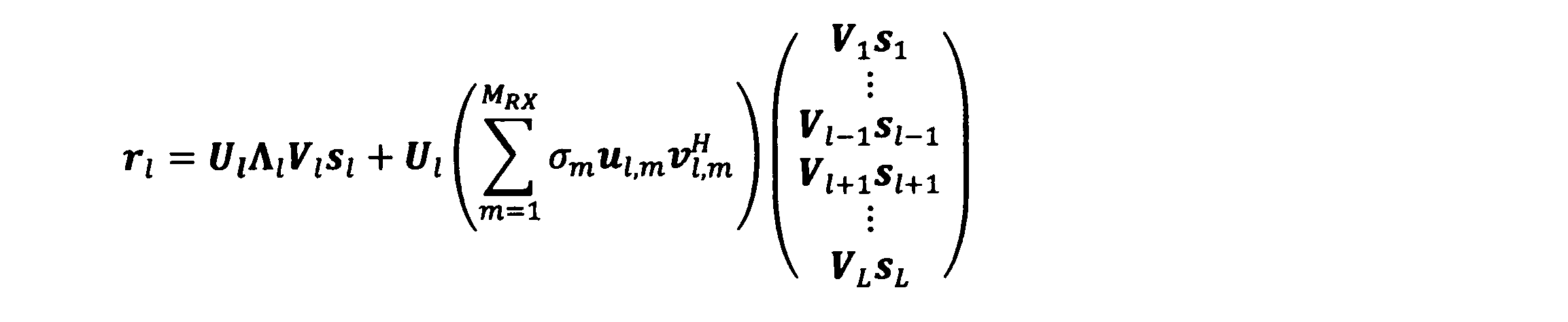
- the received signal of equation (5) can be rewritten as follows using the singular value decomposition result of equation (6).
- the received signal r 1 is as follows, and it can be seen that the interference component is suppressed after multiplication of the reception weight.
- the reception weight may be, for example, u H l, MRX-1 other than the left singular vector u H l, MRX of the minimum singular value.
- matrices u H l and MR x ⁇ l form eigenspaces that do not include the main components of interference in the received signal.
- this eigenspace if a signal is transmitted by using an eigenvector of nonzero eigenvalue as a transmission weight, signal transmission which does not include the main component of interference can be realized.
- the transmission weights V l are determined as right nonsingular vectors of nonzero singular values.
- the transmission weight is determined based on the singular value decomposition result of the multiplication result U l ⁇ l , m of the reception weight U l and the matrix ⁇ l , m .
- FIG. 3 shows the processing procedure of the first embodiment of the OAM multiplex communication system of the present invention.
- the S / P conversion / signal processing unit 11 when a transmission signal sequence is input to the transmission station, the S / P conversion / signal processing unit 11 generates a modulation signal (S11).
- a known signal sequence is transmitted from the reference signal transmission unit 16 of the transmission station (S12).
- the channel state acquisition unit 26 estimates responses ⁇ l and ⁇ l, k of each channel based on the known signal sequence (S21).
- the weight operation unit 27 performs singular value decomposition of Equations (5) and (8) based on the estimated channel responses ⁇ l and ⁇ l, k to determine the transmission weight V l and the reception weight U l (S22), sets the receiving weight U l to each reception weight multiplying unit 23 of the receiving station. Further, the feedback unit 28 sets the transmission weight V l determined by the weight calculating unit 27 in the transmission weight multiplying unit 13 of the transmitting station (S23).
- the transmission weight multiplier unit 13 of the transmission station multiplies the transmission weight V l the modulated signal generated in step S11 (S13). Further, the transmission OAM mode generation processing unit 14 performs the OAM mode generation processing by DFT operation on the modulated signal obtained by multiplying a transmission weight V l (S14), the transmission signal of each OAM modes from each transmit UCA15 transmitting station (S15).
- Each reception UCA 21 of the reception station receives the signal transmitted from the transmission station (S24), and the reception OAM mode separation processor 22 performs the OAM mode separation processing by the IDFT operation (S25).
- the reception weight multiplying unit 23 multiplies the reception weight U l to the received signal of each OAM mode (S26).
- the signal processing / P / S conversion unit 24 demodulates the received signal in which the inter-mode interference is suppressed by the above processing and converts it into a bit string, and further performs P / S conversion to align the original information bit string and output it. To do (S27).
- FIG. 4 shows a modified configuration of the first embodiment of the OAM multiplex communication system of the present invention.
- the transmitting station includes an S / P conversion / signal processing unit 11, L first transmission weight multiplication units 13-1 to Lth transmission weight multiplication units 13-L, and M TX transmission UCAs 15-1 to It comprises M TX first transmission OAM mode generation processing units 14-1 to M TX transmission OAM mode generation processing units 14-M TX corresponding to 15-M TX and a weight calculation unit 17, respectively.
- the receiving station includes M RX first reception OAM mode separation processing units 22-1 to M RX reception OAM mode separation processing units 22-M RX corresponding to M RX reception UCAs 21-1 to 21-M RX , respectively.
- the L reception weight multiplication unit 23-1 to the Lth reception weight multiplication unit 23-L, the signal processing / P / S conversion unit 24, and the weight calculation unit 29 are provided.
- the difference from the first embodiment shown in FIG. 2 is that the receiving station does not perform channel estimation, and the transmitting station and the receiving station independently determine the transmission weight and the reception weight. That is, in the configuration of FIG. 4, the channel response is estimated in advance in the transmitting station and the receiving station, and the estimated value is held by the weight calculating unit 17 of the transmitting station and the weight calculating unit 29 of the receiving station. Reference numerals 17 and 29 determine the transmission weight and the reception weight based on the channel response, and set them in the transmission weight multiplication unit 13 and the reception weight multiplication unit 23.
- FIG. 5 shows a processing procedure of a modified configuration of the first embodiment of the OAM multiplex communication system of the present invention.
- 5 when the transmission signal sequences to the transmitting station is input, and determines a transmission weight V l based on the channel response value weight calculating unit 17 holds in advance, is set in each transmission weight multiplying unit 13 (S31 ).
- the S / P conversion / signal processing unit 11 generates a modulation signal (S32) .
- the transmission weight multiplying unit 13 multiplies the transmission weight V l to the generated modulation signal (S33).
- the transmission OAM mode generation processing unit 14 performs the OAM mode generation processing by DFT operation on the modulated signal obtained by multiplying a transmission weight V l (S34), the signal of each OAM mode is transmitted from each transmitting UCA15 ( S35).
- the receiving station determines the reception weight U l based on the channel response value weight calculating unit 29 holds in advance, set for each reception weight multiplying unit 23 (S41).
- Each reception UCA 21 receives the signal transmitted from the transmission station (S42), and the reception OAM mode separation processing unit 22 performs the OAM mode separation processing by the IDFT operation (S43).
- the reception weight multiplying unit 23 multiplies the reception weight U l to the received signal of each OAM mode (S44).
- the signal processing / P / S conversion unit 24 demodulates the received signal in which the inter-mode interference is suppressed by the above processing and converts it into a bit string, and further performs P / S conversion to align the original information bit string and output it. To do (S45).
- FIG. 6 shows the configuration of the second embodiment of the OAM multiplex communication system of the present invention.
- the transmitting station includes an S / P conversion / signal processing unit 12 and L first transmission weight multiplying units 13-1 to Lth transmission weight multiplying units 13- to which M 1 to M L signals are input, respectively.
- the signal transmission unit 16 is configured.
- the receiving station includes M RX first reception OAM mode separation processing units 22-1 to M RX reception OAM mode separation processing units 22-M RX corresponding to M RX reception UCAs 21-1 to 21-M RX , respectively. , L first reception weight multiplication units 23-1 to L-th reception weight multiplication units 23-L, signal processing / P / S conversion units 25 for receiving M 1 to M L reception signals, channel state acquisition units 26, a weight calculation unit 27 and a feedback unit 28.
- the difference between the OAM multiplex communication system according to the second embodiment and the first embodiment is that there are a plurality of modulation signals to be input to one transmission weight multiplication unit 13 and a plurality of reception signals output from one reception weight multiplication unit 23 There is a strain. Further, as the number of input systems increases, the matrix sizes of the transmission weight and the reception weight also differ, and the processing methods of the transmission weight multiplication unit 13 and the reception weight multiplication unit 23 differ. As a result, by selecting and using an OAM mode with high signal-to-interference-plus-noise ratio (SINR) among the OAM modes, the throughput can be compensated while compensating for tilt, misalignment, and multipath interference. The point of improvement is different from the first embodiment.
- SINR signal-to-interference-plus-noise ratio
- the l-th transmission weight multiplication unit 13-l inputs M l parallel modulation signals s l and outputs modulation signals s ′ l obtained by multiplying each modulation signal by the transmission weight V l .
- the l-th reception weight multiplication unit 23-l outputs the first reception OAM mode separation processing unit 22-1 to the M-th RX reception OAM mode separation processing unit 22- MR (r l [l], ..., r MRX [ l]) Input T , and output a reception signal r l multiplied by the reception weight U l .
- the vector space including the main component of the interference component is eliminated by multiplying (u H l, MRX- (Ml-1) ,..., U H l, MRX-1 , u H l, MRX ) be able to.
- the matrix of the main signal component (u H l, MRX- (Ml -1), ..., u H l, MRX-1, u H l, MRX) singular vectors obtained by singular value decomposition of the lambda l
- the transmission weight and the reception weight are determined using this. This enables eigenmode transmission while reducing interference between modes.
- the singular value decomposition results of the matrix are as follows.
- ⁇ l (img) and ⁇ l (ker) are not (u H l, MRX- (Ml-1) , ..., u H l, MRX-1 , u H l, MRX ) ⁇ l respectively A left singular vector corresponding to a zero singular value and a left singular vector corresponding to a zero singular value, and l l (img) and l l (ker) are right singular vectors corresponding to non-zero singular values of the same matrix, It is a right singular vector corresponding to a zero singular value.
- the transmission weight V l and the reception weight U l are determined as in the following equation (11).
- the reception signal r l is output as a signal whose interference is suppressed as follows.
- the multiple number M l may be a selection criterion according to the total capacity calculated from SINR or the like, or may be determined according to another selection criterion. Alternatively, the multiplex number M l may be fixed beforehand by the system.
- FIG. 7 shows the processing procedure of the second embodiment of the OAM multiplex communication system of the present invention.
- the transmitting station transmits a known signal sequence from the reference signal transmission unit 16 (S51).
- the channel state acquisition unit 26 estimates responses ⁇ l and ⁇ l, k of each channel based on the known signal sequence (S61).
- the weight operation unit 27 performs singular value decomposition of Expression (9) based on the estimated channel response ⁇ l and ⁇ l, k to calculate the transmission weight V l and the reception weight U l as the expression (10).
- the multiplexing number M l is determined, and the reception weight U l is set to each reception weight multiplication unit 23 (S 62).
- the multiplex number M l may be predetermined or may be selected adaptively.
- the feedback unit 28 sets the multiplexing number M 1 determined by the weight calculation unit 27 in the S / P conversion / signal processing unit 12 of the transmission station, and sets the transmission weight V 1 in each transmission weight multiplication unit 13 of the transmission station (S63).
- the transmitting station generates a modulated signal in the S / P conversion / signal processing unit 12 in which the multiplexing number M 1 is set (S 52) . Then, the transmission weight multiplying unit 13 multiplies the transmission weight V l for the generated modulated signal (S53). Further, the transmission OAM mode generation processing unit 14 performs the OAM mode generation processing by DFT operation on the modulated signal obtained by multiplying a transmission weight V l (S54), the transmission signal of each OAM modes from each transmit UCA15 transmitting station (S55).
- Each reception UCA 21 of the reception station receives the signal transmitted from the transmission station (S64), and the reception OAM mode separation processor 22 performs OAM mode separation processing by IDFT calculation (S65).
- the reception weight multiplying unit 23 multiplies the reception weight U l to the received signal of each OAM mode (S66).
- the signal processing / P / S conversion unit 25 demodulates the received signal in which the inter-mode interference is suppressed by the above processing, converts it into a bit string, and further performs P / S conversion to align the original information bit string and output it. (S67).
- FIG. 8 shows a modified configuration of the second embodiment of the OAM multiplex communication system of the present invention.
- the transmitting station includes an S / P conversion / signal processing unit 12, L first transmission weight multiplying units 13-1 to Lth transmission weight multiplying units 13-L, and M TX transmission UCAs 15-1 to It comprises M TX first transmission OAM mode generation processing units 14-1 to M TX transmission OAM mode generation processing units 14-M TX corresponding to 15-M TX and a weight calculation unit 17, respectively.
- the receiving station includes M RX first reception OAM mode separation processing units 22-1 to M RX reception OAM mode separation processing units 22-M RX corresponding to M RX reception UCAs 21-1 to 21-M RX , respectively. , L first reception weight multiplication units 23-1 to L-th reception weight multiplication units 23-L, signal processing / P / S conversion units 25 that receive M 1 to M L reception signals, and weight calculation units 29 It consists of
- the difference from the second embodiment shown in FIG. 6 is that the receiving station does not perform channel estimation, and the transmitting station and the receiving station independently determine the transmission weight and the reception weight. That is, in the configuration of FIG. 8, the channel response is estimated in advance in the transmitting station and the receiving station, and the estimated value is held by the weight calculating unit 17 of the transmitting station and the weight calculating unit 29 of the receiving station. Reference numerals 17 and 29 determine the transmission weight and the reception weight based on the channel response, and set them in the transmission weight multiplication unit 13 and the reception weight multiplication unit 23. Also, pre and predetermined multiplex number M l, the receiving station and transmitting station together for having information multiplex number M l, can communicate without using the feedback process.
- the processing procedure in the modification of the second embodiment of the OAM multiplex communication system according to the present invention is different from the processing procedure in the modification of the first embodiment shown in FIG. 5 in the S / P conversion / signal processing unit 12 of the transmitting station.
- the same process is performed except that a modulation signal corresponding to the number M l is generated and the reception signal demodulates the reception signal corresponding to the multiplexing number M l at the signal processing / P / S conversion unit 25.
Landscapes
- Engineering & Computer Science (AREA)
- Signal Processing (AREA)
- Computer Networks & Wireless Communication (AREA)
- Power Engineering (AREA)
- Physics & Mathematics (AREA)
- Mathematical Physics (AREA)
- Radio Transmission System (AREA)
Abstract
送信UCAと受信UCAとの間の光軸のずれ、チルト、反射波などによって生じるモード間干渉を低演算量で抑圧する。 【解決手段】送信局は複数の送信信号系列をそれぞれ入力し、送信信号系列ごとに送信ウエイトを乗算し、M-UCAを構成するUCAに対応するMTX個の信号に変換して出力する複数の送信ウエイト乗算部と、UCA対応の信号を入力して離散フーリエ変換を行い、それぞれ対応するUCAに出力するMTX個の送信OAMモード生成処理部とを備え、受信局はM-UCAを構成するUCAからそれぞれ信号を入力して逆フーリエ変換を行い、受信信号系列ごとに出力するMRX個の受信OAMモード分離処理部と、受信信号系列ごとに受信ウエイトを乗算し、空間多重伝送された受信信号系列を分離するとともに、空間多重されたOAMモード間の干渉を抑圧して出力する複数の受信ウエイト乗算部とを備える。
Description
本発明は、電磁波の軌道角運動量(Orbital Angular Momentum:OAM)を用いて無線信号を空間多重伝送するOAM多重通信システムおよびモード間干渉除去方法に関する。
OAMを用いて無線信号を空間多重伝送する技術は、無線通信の伝送容量向上のために効果的である。OAMモードをもつ電波は、ビームの伝搬軸を中心とする回転方向に沿って等位相面が螺旋状に分布することを特徴とし、等位相面が形成する螺旋の周期が2π×kのモードをOAMモードkと呼ぶ。異なるOAMモード同士は回転方向に直交性を有するため、複数のOAMモードの信号を空間多重伝送できる。例えば、OAMモード1とOAMモード2の信号は空間上で互いに直交しているため、送信アンテナからこれらのモードを同時に送信しても、受信側でOAMモード1とOAMモード2の信号を分離できる。OAMモードの生成には、複数のアンテナ素子を等間隔に円形配置した等間隔円形アレーアンテナ(Uniform Circular Array:UCA)を用いる方法が報告されている。
OAM多重通信システムでは、送受信アンテナとして用いるUCA同士を正面対向配置させることで、OAMモード伝送に係る送信側のウエイト乗算および受信側のウエイト乗算を送受信アンテナ間の距離に関わらず一律化することができる(非特許文献1)。ここでは、送受信のウエイト乗算にかかるDFT(Discrete Fourier Transform)処理を行うバトラーマトリクス回路を実装し、OAMモード伝送に係るディジタル信号処理の演算量を低減している。
図9は、従来のOAM多重通信システムの構成例を示す。
図9において、送信局および受信局のアンテナは、それぞれアンテナ素子をL素子備えるUCAである。説明を簡略化するために、送信局と受信局が備えるUCAのアンテナ素子数と空間多重数は同一(L多重)とする。
図9において、送信局および受信局のアンテナは、それぞれアンテナ素子をL素子備えるUCAである。説明を簡略化するために、送信局と受信局が備えるUCAのアンテナ素子数と空間多重数は同一(L多重)とする。
送信局のS(シリアル)/P(パラレル)変換・信号処理部11は、送信信号系列を入力すると、L個の並列なビット列に変換し、各ビット列に対して変調を行い、送信信号系列sl (l=1,2,…,L) を出力する。送信OAMモード生成処理部14は、送信信号系列sl を入力してDFT演算を行い、送信UCA15の各アンテナ素子に出力する。送信UCA15は、送信OAMモード生成処理部14の出力信号を送信する。
受信局の受信UCA21は、空間多重されたOAMモードの信号を各アンテナ素子で受信し、受信OAMモード分離処理部22に出力する。受信OAMモード分離処理部22は、各アンテナ素子の受信信号に対してIDFT(Inverse DFT)演算を行い、空間多重されたOAMモードを分離し、受信信号系列rl (l=1,2,…,L) を出力する。信号処理・P/S変換部24は、各受信信号系列を復調し、もとの順番に並び替えた受信信号系列を出力する。
図9には、送信UCA15と受信UCA21の位置関係を模式的に示している。送信UCA15および受信UCA21を構成する円形配置のアンテナ素子(図中●で示す)の中心P,Qを結ぶ直線(光軸)Wに対して、各アンテナ開口面が垂直になるように配置される。このとき、送信UCA15と受信UCA21との間のチャネル行列Hは、送受信UCA間の距離に関わらず巡回行列である。巡回行列の性質によれば、チャネル行列はDFT演算とIDFT演算によって固有値分解されるため、図9のOAM多重通信システムにおいて受信信号rl は常に、

E. Sasaki, M. Hirabe, T. Maru, N. Zein, "Pragmatic OAM with polarization multiplexing transmission for future 5G ultra-high capacity radio ", in proc. of EuMA2016, Oct. 2016.
非特許文献1の構成では、送信UCAと受信UCAが正面で対向する位置に配置され、かつ、反射波がない見通し環境に限定される。しかし、実運用上は、送信UCAと受信UCAが正面対向配置からずれた位置に固定設置されている場合や、周辺環境による反射波などの影響も考慮する必要がある。このような影響に起因して、送信UCAと受信UCA間のチャネル行列が理想的な正面対向配置から乖離しているときは、受信側のバトラーマトリクス回路の出力段においてOAMモード間の干渉が残留する。そのため、OAMモードlの受信信号rl は、

本発明は、送信UCAと受信UCAとの間の光軸のずれ、チルト、反射波などによって生じるモード間干渉を低演算量で抑圧することができるOAM多重通信システムおよびモード間干渉除去方法を提供することを目的とする。
第1の発明は、複数のアンテナ素子を円形に等間隔で配置したUCAを、同心円状かつ等間隔に配置した径の異なる複数MTX個のUCAからなるM-UCAを用いた送信アンテナを含む送信局と、送信局と同様に複数MRX個のUCAからなるM-UCAを用いた受信アンテナを含む受信局とを備え、OAMモードを用いて複数の送信信号系列を空間多重伝送するOAM多重通信システムであって、送信局は、複数の送信信号系列をそれぞれ入力し、送信信号系列ごとに送信ウエイトを乗算し、M-UCAを構成するUCAに対応するMTX個の信号に変換して出力する複数の送信ウエイト乗算部と、複数の送信ウエイト乗算部がそれぞれ出力するUCA対応の信号を入力して離散フーリエ変換を行い、それぞれ対応するUCAに出力するMTX個の送信OAMモード生成処理部とを備え、受信局は、M-UCAを構成するUCAからそれぞれ信号を入力して逆フーリエ変換を行い、受信信号系列ごとに出力するMRX個の受信OAMモード分離処理部と、受信OAMモード分離処理部が出力する受信信号系列ごとに受信ウエイトを乗算し、空間多重伝送された受信信号系列を分離するとともに、空間多重されたOAMモード間の干渉を抑圧して出力する複数の受信ウエイト乗算部とを備える。
第1の発明のOAM多重通信システムにおいて、送信ウエイト乗算部は、複数の送信信号系列を入力して送信ウエイトを乗算する構成であり、受信ウエイト乗算部は、空間多重伝送された複数の受信信号系列を分離する構成である。
第1の発明のOAM多重通信システムにおいて、送信局から受信局に送信された既知信号系列に対する受信OAMモード分離処理部の出力値からチャネル推定を行い、送信ウエイトと受信ウエイトを決定するウエイト演算部を備え、受信ウエイトは受信ウエイト乗算部に設定し、送信ウエイトは受信局から送信局へフィードバックされて送信ウエイト乗算部に設定し、空間多重伝送されたOAMモード間の干渉成分を抑圧する構成である。
第2の発明は、複数のアンテナ素子を円形に等間隔で配置したUCAを、同心円状かつ等間隔に配置した径の異なる複数MTX個のUCAからなるM-UCAを用いた送信アンテナを含む送信局と、送信局と同様に複数MRX個のUCAからなるM-UCAを用いた受信アンテナを含む受信局とを備え、OAMモードを用いて複数の送信信号系列を空間多重伝送するOAM多重通信システムのモード間干渉除去方法であって、送信局は、複数の送信ウエイト乗算部で、複数の送信信号系列をそれぞれ入力し、送信信号系列ごとに送信ウエイトを乗算し、M-UCAを構成するUCAに対応するMTX個の信号に変換して出力し、MTX個の送信OAMモード生成処理部で、複数の送信ウエイト乗算部がそれぞれ出力するUCA対応の信号を入力して離散フーリエ変換を行い、それぞれ対応するUCAに出力し、受信局は、MRX個の受信OAMモード分離処理部で、M-UCAを構成するUCAからそれぞれ信号を入力して逆フーリエ変換を行い、受信信号系列ごとに出力し、複数の受信ウエイト乗算部で、受信OAMモード分離処理部が出力する受信信号系列ごとに受信ウエイトを乗算し、空間多重伝送された受信信号系列を分離するとともに、空間多重されたOAMモード間の干渉を抑圧して出力する。
第2の発明のOAM多重通信システムのモード間干渉除去方法において、送信局から受信局に送信された既知信号系列に対する受信OAMモード分離処理部の出力値からチャネル推定を行い、送信ウエイトと受信ウエイトを決定し、受信ウエイトは受信ウエイト乗算部に設定し、送信ウエイトは受信局から送信局へフィードバックされて送信ウエイト乗算部に設定し、空間多重されたOAMモード間の干渉を抑圧する。
第2の発明のOAM多重通信システムのモード間干渉除去方法において、受信OAMモード分離処理部の出力のうち、特定の離散周波数成分に残留する他離散周波数成分からの干渉成分を表す行列の特異値分解の結果と、自離散周波数成分を表す行列の特異値分解の結果とに基づき、空間多重化された信号同士の干渉を抑圧するための送信ウエイトおよび受信ウエイトを決定してもよい。
また、受信OAMモード分離処理部の出力に生じる他離散周波数成分からの干渉成分を表す行列の特異値分解の結果のうち、左特異ベクトルに属するベクトルのうちの一つ以上のベクトルと直交するベクトルを含むウエイトを受信ウエイトとしてもよい。
また、受信OAMモード分離処理部の出力に生じる他離散周波数成分からの干渉成分を表す行列の特異値分解の結果のうち、左特異ベクトルに属するベクトルと直交するベクトルと、自離散周波数成分を表す行列との乗算結果の特異値分解を基に、送信ウエイトおよび受信ウエイトを決定してもよい。
また、空間多重する信号の多重数は、受信信号品質に応じた合計レートを最大にする規範に基づいて決定するか、あらかじめ決定してもよい。
本発明は、送信ウエイトおよび受信ウエイトを適宜設定することにより、送信アンテナと受信アンテナが正面対向配置からずれた位置に固定設置されている場合や、周辺環境による反射波などに起因して生じるOAMモード間の干渉を抑圧することができる。
図1は、本発明のOAM多重通信システムのM-UCAの構成例を示す。
図1において、M(Multi)-UCAは、複数のUCAを同心円状かつ等間隔に配置した構成である。ここでは、4つのUCAを配置した構成を示し、内側のUCAから順番に、第1UCA,第2UCA,第3UCA,第4UCAとする。なお、送信UCAの場合は第n送信UCAと呼び、受信UCAの場合は第n受信UCAと呼ぶ。各UCAは8素子のアンテナ素子(図中、●で示す)を備える例を示すが、各UCAのアンテナ素子数は必ずしも同数である必要はない。
図1において、M(Multi)-UCAは、複数のUCAを同心円状かつ等間隔に配置した構成である。ここでは、4つのUCAを配置した構成を示し、内側のUCAから順番に、第1UCA,第2UCA,第3UCA,第4UCAとする。なお、送信UCAの場合は第n送信UCAと呼び、受信UCAの場合は第n受信UCAと呼ぶ。各UCAは8素子のアンテナ素子(図中、●で示す)を備える例を示すが、各UCAのアンテナ素子数は必ずしも同数である必要はない。
以下の説明に用いる各記号の定義は次の通りである。

(実施例1)
図2は、本発明のOAM多重通信システムの実施例1の構成を示す。
図2において、送信局は、S/P変換・信号処理部11、L個の第1送信ウエイト乗算部13-1~第L送信ウエイト乗算部13-L、MTX個の送信UCA15-1~15-MTXにそれぞれ対応するMTX個の第1送信OAMモード生成処理部14-1~第MTX送信OAMモード生成処理部14-MTX、参照信号送信部16により構成される。
図2は、本発明のOAM多重通信システムの実施例1の構成を示す。
図2において、送信局は、S/P変換・信号処理部11、L個の第1送信ウエイト乗算部13-1~第L送信ウエイト乗算部13-L、MTX個の送信UCA15-1~15-MTXにそれぞれ対応するMTX個の第1送信OAMモード生成処理部14-1~第MTX送信OAMモード生成処理部14-MTX、参照信号送信部16により構成される。
受信局は、MRX個の受信UCA21-1~21-MRXにそれぞれ対応するMRX個の第1受信OAMモード分離処理部22-1~第MRX受信OAMモード分離処理部22-MRX、L個の第1受信ウエイト乗算部23-1~第L受信ウエイト乗算部23-L、信号処理・P/S変換部24、チャネル状態取得部26、ウエイト演算部27、フィードバック部28により構成される。
実施例1のOAM多重通信システムは、従来構成と異なり、M-UCAを用いたアンテナ構成となる。また、チャネル情報を取得して演算したウエイトを送信局にフィードバックする点、および、送信局および受信局でチャネル情報に基づき演算したウエイトを乗算する点で異なる。
はじめに、実施例1の送信局および受信局の入出力関係を数式表現する。送信局は、入力した送信信号系列をS/P変換してL個の並列なビット列に変換し、各ビット列を変調して送信信号sl (l=1,2,…,L)を生成する。第l送信ウエイト乗算部13-lは、送信信号sl に対して送信ウエイトVl を乗算し、s'lを出力する。

第m送信OAMモード生成処理部14-mは、第1送信ウエイト乗算部13-1~第L送信ウエイト乗算部13-Lの出力の第m番目の信号s'l[m],(l=1,2,…,L) を並べた信号ベクトル
S'[m]=(s'1[m],…,s'L[m])T
を入力し、S'[m] に対してDFT行列Dm TX を乗算して出力する。ここで、Dm TX は、その第p行q列成分が

で与えられるNTX(m)×LのDFT行列であり、式中のjは虚数単位を表し、l(q) は第q列のDFTの離散周波数インデックスを表す。
S'[m]=(s'1[m],…,s'L[m])T
を入力し、S'[m] に対してDFT行列Dm TX を乗算して出力する。ここで、Dm TX は、その第p行q列成分が
なお、DFT演算に係る処理は、非特許文献1と同一のバトラーマトリクスを用いたアナログ回路で実施してもよく、ディジタル信号処理で実施してもよい。
第1送信OAMモード生成処理部14-1~第MTX送信OAMモード生成処理部14-MTXの出力信号は、各DFT演算部と接続する送信UCA15-1~15-MTXから受信UCAに向けて送信される。このとき、第k受信UCA21-kで受信される信号は以下の通りである。
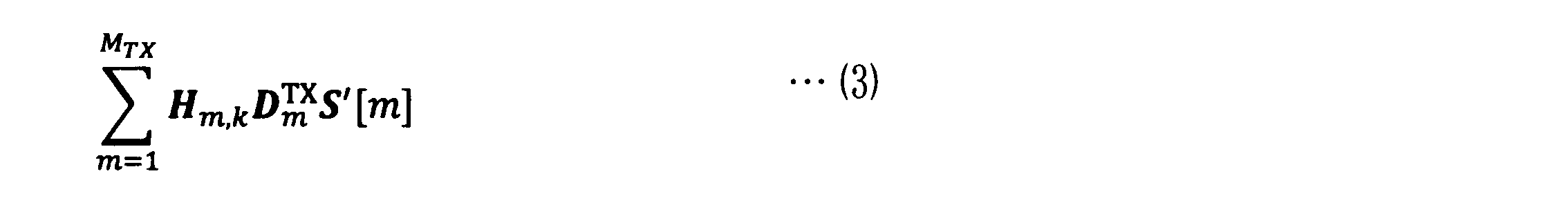
式(3) では説明の簡略化のため、雑音項を無視している。
第1送信OAMモード生成処理部14-1~第MTX送信OAMモード生成処理部14-MTXの出力信号は、各DFT演算部と接続する送信UCA15-1~15-MTXから受信UCAに向けて送信される。このとき、第k受信UCA21-kで受信される信号は以下の通りである。
次に、受信局の第k受信OAMモード分離処理部22-kは、第k受信UCA21-kで受信した信号に対してIDFT行列Dk
RX を乗算して出力する。ここで、IDFT行列Dk
RX のp行q列成分は次のように表される。

第l受信ウエイト乗算部23-lは、第1受信OAMモード分離処理部22-1~第MRX受信OAMモード分離処理部22-MRXの第l番目の出力rk[l],(k=1,2,…,MRX) を並べたベクトルr[l]

信号処理・P/S変換部24は、受信ウエイト乗算後の信号rl から送信された情報ビット列を推定し、P/S変換後、もとの情報ビット列の順番に整列させる。
また、送信局の参照信号送信部16は、チャネル応答を推定するための既知信号系列を受信局に向けて送信する。
受信局のチャネル状態取得部26は、第1受信OAMモード分離処理部22-1~第MRX受信OAMモード分離処理部22-MRXと接続され、既知信号系列に基づきチャネル応答を推定する。推定した情報をウエイト演算部27に出力する。
ウエイト演算部27は、チャネル状態取得部26の推定値に基づき送信ウエイトおよび受信ウエイトを決定し、受信局の第1受信ウエイト乗算部23-1~第L受信ウエイト乗算部23-Lに設定し、フィードバック部28を介して、送信局の第1送信ウエイト乗算部13-1~第L送信ウエイト乗算部13-Lに設定する。
次に、ウエイト演算部27における送信ウエイトと受信ウエイトの演算方法を説明する。説明を明確化するために、受信ウエイト乗算後の信号rl に残留する干渉成分を数式表現する。初めに、送信局と受信局のM-UCA同士が正面で対向しており、干渉が生じない場合、チャネル行列Hm,k は、左からIDFT行列Dk
RX、右側からDFT行列Dm
TXを乗算することによって対角化される。したがって、第l受信ウエイト乗算部23-lから出力される信号rl は、以下のようになる。

式(4) 中のΛl は各チャネルの応答を表すMRX×MTXの行列である。式(4) より正面対向時は、インデックスlが異なる信号(異なるOAMモード)からの干渉が生じないことが分かる。したがって、従来構成と同様に、信号処理・P/S変換部24は信号rl ごとにビット列sl を他モードからの干渉なく推定できる。一方、それ以外の場合、rl は、他モードからの干渉を含んだ信号となる。

干渉成分(式(5) の第2項の信号成分)を抑圧し、通信品質を改善するための送信ウエイトVl と受信ウエイトUl の決定方法について以下に説明する。
実施例1では、干渉成分の行列を特異値分解(Singular Value Decomposition:SVD)し、干渉量の多い左特異ベクトルと直交するベクトルを受信ウエイトに採用することで干渉成分を抑圧する。
はじめに、干渉量が多い特異ベクトルを見つけるために、干渉成分の行列Λl
(INT)を特異値分解すると式(6) のようになる。


式(5) の受信信号は、式(6) の特異値分解結果を用いて次のように書き直すことができる。
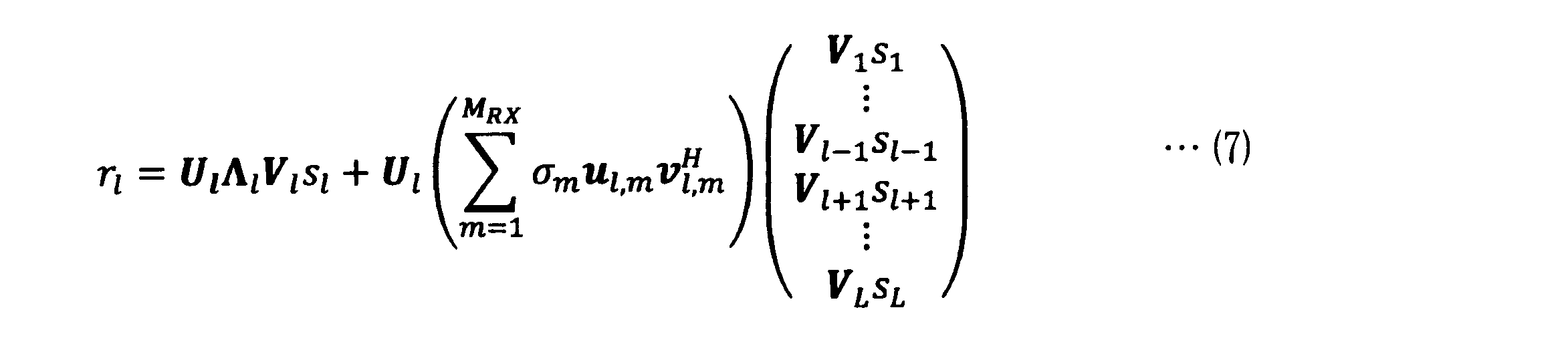
式(7) より、受信信号rl に対して左特異ベクトルul,m の複素共役転置uH
l,mを乗算すれば、左特異ベクトル同士の直交性から第l受信ウエイト乗算部23-lの出力に含まれる干渉成分(式(7) の第2項)のうちσmul,mvH
l,m以外の成分を除去できることがわかる。受信信号の干渉を効果的に抑圧するには、特異値が最小の左特異ベクトルuH
l,MRXを受信ウエイトUl に採用し、干渉の大きい項を除去すればよい。このとき受信信号rl は以下のようになり、受信ウエイト乗算後に干渉成分が抑圧されたことが分かる。なお、受信ウエイトは最小特異値の左特異ベクトルuH
l,MRX以外の例えば、uH
l,MRX-1であってもよい。

一方、行列uH
l,MRXΛl は、受信信号に干渉の主成分を含まない固有空間を形成する。この固有空間のうち、非ゼロの固有値の固有ベクトルを送信ウエイトとして信号を送信すれば、干渉の主成分を含まない信号伝送が実現できる。具体的には、送信ウエイトVl を、行列uH
l,MRXΛl を特異値分解することで得られる右特異ベクトルのうち、非ゼロ特異値の右特異ベクトルに決定する。

図3は、本発明のOAM多重通信システムの実施例1の処理手順を示す。
図3において、送信局に送信信号系列が入力すると、S/P変換・信号処理部11は変調信号を生成する(S11) 。次に、送信局の参照信号送信部16から既知信号系列を送信する(S12) 。受信局は、既知信号系列を受信すると、チャネル状態取得部26が既知信号系列に基づき、各チャネルの応答Λl およびΛl,k を推定する(S21)。ウエイト演算部27は、推定したチャネルの応答Λl およびΛl,k に基づき、式(5) および式(8) の特異値分解を実施し、送信ウエイトVl と受信ウエイトUl を決定し(S22)、受信ウエイトUl を受信局の各受信ウエイト乗算部23に設定する。さらに、フィードバック部28は、ウエイト演算部27で決定した送信ウエイトVl を送信局の各送信ウエイト乗算部13に設定する(S23)。
図3において、送信局に送信信号系列が入力すると、S/P変換・信号処理部11は変調信号を生成する(S11) 。次に、送信局の参照信号送信部16から既知信号系列を送信する(S12) 。受信局は、既知信号系列を受信すると、チャネル状態取得部26が既知信号系列に基づき、各チャネルの応答Λl およびΛl,k を推定する(S21)。ウエイト演算部27は、推定したチャネルの応答Λl およびΛl,k に基づき、式(5) および式(8) の特異値分解を実施し、送信ウエイトVl と受信ウエイトUl を決定し(S22)、受信ウエイトUl を受信局の各受信ウエイト乗算部23に設定する。さらに、フィードバック部28は、ウエイト演算部27で決定した送信ウエイトVl を送信局の各送信ウエイト乗算部13に設定する(S23)。
次に、送信局の各送信ウエイト乗算部13は、ステップS11で生成した変調信号に対して送信ウエイトVl を乗算する(S13)。さらに、送信OAMモード生成処理部14は、送信ウエイトVl を乗算した変調信号に対してDFT演算によりOAMモード生成処理を行い(S14)、各OAMモードの信号が送信局の各送信UCA15から送信される(S15)。
受信局の各受信UCA21は、送信局から送信された信号を受信し(S24)、受信OAMモード分離処理部22でIDFT演算によりOAMモード分離処理を行う(S25)。次に、各受信ウエイト乗算部23は、各OAMモードの受信信号に対して受信ウエイトUl を乗算する(S26)。信号処理・P/S変換部24は、以上の処理によりモード間干渉が抑圧された受信信号を復調してビット列に変換し、さらにP/S変換して元の情報ビット列の並びに整列させて出力する(S27)。
(実施例1の変形)
図4は、本発明のOAM多重通信システムの実施例1の変形構成を示す。
図4において、送信局は、S/P変換・信号処理部11、L個の第1送信ウエイト乗算部13-1~第L送信ウエイト乗算部13-L、MTX個の送信UCA15-1~15-MTXにそれぞれ対応するMTX個の第1送信OAMモード生成処理部14-1~第MTX送信OAMモード生成処理部14-MTX、ウエイト演算部17により構成される。
図4は、本発明のOAM多重通信システムの実施例1の変形構成を示す。
図4において、送信局は、S/P変換・信号処理部11、L個の第1送信ウエイト乗算部13-1~第L送信ウエイト乗算部13-L、MTX個の送信UCA15-1~15-MTXにそれぞれ対応するMTX個の第1送信OAMモード生成処理部14-1~第MTX送信OAMモード生成処理部14-MTX、ウエイト演算部17により構成される。
受信局は、MRX個の受信UCA21-1~21-MRXにそれぞれ対応するMRX個の第1受信OAMモード分離処理部22-1~第MRX受信OAMモード分離処理部22-MRX、L個の第1受信ウエイト乗算部23-1~第L受信ウエイト乗算部23-L、信号処理・P/S変換部24、ウエイト演算部29により構成される。
図2に示す実施例1との違いは、受信局でチャネル推定を実施しない点と、送信局と受信局とが独立に送信ウエイトおよび受信ウエイトを決定する点にある。すなわち、図4の構成では、送信局および受信局においてあらかじめチャネル応答が推定されており、推定値は送信局のウエイト演算部17および受信局のウエイト演算部29が保持しており、ウエイト演算部17,29がチャネル応答に基づいて送信ウエイトと受信ウエイトを決定し、送信ウエイト乗算部13および受信ウエイト乗算部23に設定する。
図5は、本発明のOAM多重通信システムの実施例1の変形構成の処理手順を示す。
図5において、送信局に送信信号系列が入力すると、ウエイト演算部17が事前に保持しているチャネル応答値に基づいて送信ウエイトVl を決定し、各送信ウエイト乗算部13に設定する(S31)。S/P変換・信号処理部11は、変調信号を生成する(S32) 。次に、各送信ウエイト乗算部13は、生成した変調信号に対して送信ウエイトVl を乗算する(S33)。さらに、送信OAMモード生成処理部14は、送信ウエイトVl を乗算した変調信号に対してDFT演算によりOAMモード生成処理を行い(S34)、各OAMモードの信号が各送信UCA15から送信される(S35)。
図5において、送信局に送信信号系列が入力すると、ウエイト演算部17が事前に保持しているチャネル応答値に基づいて送信ウエイトVl を決定し、各送信ウエイト乗算部13に設定する(S31)。S/P変換・信号処理部11は、変調信号を生成する(S32) 。次に、各送信ウエイト乗算部13は、生成した変調信号に対して送信ウエイトVl を乗算する(S33)。さらに、送信OAMモード生成処理部14は、送信ウエイトVl を乗算した変調信号に対してDFT演算によりOAMモード生成処理を行い(S34)、各OAMモードの信号が各送信UCA15から送信される(S35)。
一方、受信局は、ウエイト演算部29が事前に保持しているチャネル応答値に基づいて受信ウエイトUl を決定し、各受信ウエイト乗算部23に設定する(S41)。各受信UCA21は、送信局から送信された信号を受信し(S42)、受信OAMモード分離処理部22でIDFT演算によりOAMモード分離処理を行う(S43)。次に、各受信ウエイト乗算部23は、各OAMモードの受信信号に対して受信ウエイトUl を乗算する(S44)。信号処理・P/S変換部24は、以上の処理によりモード間干渉が抑圧された受信信号を復調してビット列に変換し、さらにP/S変換して元の情報ビット列の並びに整列させて出力する(S45)。
(実施例2)
図6は、本発明のOAM多重通信システムの実施例2の構成を示す。
図6において、送信局は、S/P変換・信号処理部12、それぞれM1 ~ML の信号を入力するL個の第1送信ウエイト乗算部13-1~第L送信ウエイト乗算部13-L、MTX個の送信UCA15-1~15-MTXにそれぞれ対応するMTX個の第1送信OAMモード生成処理部14-1~第MTX送信OAMモード生成処理部14-MTX、参照信号送信部16により構成される。
図6は、本発明のOAM多重通信システムの実施例2の構成を示す。
図6において、送信局は、S/P変換・信号処理部12、それぞれM1 ~ML の信号を入力するL個の第1送信ウエイト乗算部13-1~第L送信ウエイト乗算部13-L、MTX個の送信UCA15-1~15-MTXにそれぞれ対応するMTX個の第1送信OAMモード生成処理部14-1~第MTX送信OAMモード生成処理部14-MTX、参照信号送信部16により構成される。
受信局は、MRX個の受信UCA21-1~21-MRXにそれぞれ対応するMRX個の第1受信OAMモード分離処理部22-1~第MRX受信OAMモード分離処理部22-MRX、L個の第1受信ウエイト乗算部23-1~第L受信ウエイト乗算部23-L、それぞれM1 ~ML の受信信号を入力する信号処理・P/S変換部25、チャネル状態取得部26、ウエイト演算部27、フィードバック部28により構成される。
実施例2のOAM多重通信システムと実施例1との違いは、1つの送信ウエイト乗算部13へ入力する変調信号が複数系統存在し、1つの受信ウエイト乗算部23から出力される受信信号が複数系統存在する。また、入力の系統数が増えたことに伴い、送信ウエイトと受信ウエイトの行列サイズも異なり、送信ウエイト乗算部13および受信ウエイト乗算部23の処理方法が異なる。これにより、OAMモードのうち、SINR (Signal-to-interference-plus-noise ratio)が高いOAMモードを選択して使用することで、チルトや軸ずれ、マルチパスの干渉を補償しつつ、スループットを向上させる点が実施例1と異なる。
第l送信ウエイト乗算部13-lは、Ml 個の並列な変調信号sl を入力し、各変調信号に対して送信ウエイトVl を乗算した変調信号s'lを出力する。

第l受信ウエイト乗算部23-lは、第1受信OAMモード分離処理部22-1~第MRX受信OAMモード分離処理部22-MRXの出力(rl[l],…,rMRX[l])Tを入力し、受信ウエイトUlを乗算した受信信号rl を出力する 。

送信アンテナと受信アンテナが理想的な見通し環境、かつ、正面対向配置でない場合、受信信号ベクトルr l は、

であり、式(9)中の第2項の干渉成分が生じる。
以下、実施例2における送信ウエイトVl と受信ウエイトUl の決定方法について説明する。(9) の受信信号は、式(6) の特異値分解結果を用いて次のように書き直すことができる。

すなわち、(uH
l,MRX-(Ml-1),…,uH
l,MRX-1,uH
l,MRX)を乗算することで、干渉成分の主要な成分を含むベクトル空間を除去することができる。続いて、主信号成分の行列(uH
l,MRX-(Ml-1),…,uH
l,MRX-1,uH
l,MRX)Λl を特異値分解して得られる特異ベクトルを用いて、送信ウエイトと受信ウエイトを決定する。これにより、モード間の干渉を低減しつつ固有モード伝送できるようになる。同行列の特異値分解結果は、次の通りである。

ここで、Θl
(img),Θl
(ker)はそれぞれ、(uH
l,MRX-(Ml-1),…,uH
l,MRX-1,uH
l,MRX)Λlの非ゼロ特異値に対応する左特異ベクトル、ゼロ特異値に対応する左特異ベクトルであり、Φl
(img),Φl
(ker)はそれぞれ、同行列の非ゼロ特異値に対応する右特異ベクトル、ゼロ特異値に対応する右特異ベクトルである。式(10)の特異値分解結果に基づき、送信ウエイトVl および受信ウエイトUl を以下の式(11)のように決定する。


多重数Ml は、SINRなどから計算される合計容量に従う選択規範でもよく、別の選択規範に則って決めてもよい。あるいは、多重数Ml は事前にシステムが固定的に決めているものでもよい。
図7は、本発明のOAM多重通信システムの実施例2の処理手順を示す。
図7において、送信局は、参照信号送信部16から既知信号系列を送信する(S51) 。受信局は、既知信号系列を受信すると、チャネル状態取得部26が既知信号系列に基づき、各チャネルの応答Λl およびΛl,k を推定する(S61)。次に、ウエイト演算部27は、推定したチャネルの応答Λl およびΛl,k に基づき、式(9) の特異値分解を実施し、送信ウエイトVl と受信ウエイトUl を式(10)のように決定するとともに多重数Ml を決定し、受信ウエイトUl を各受信ウエイト乗算部23に設定する(S62)。多重数Ml は、あらかじめ決められているものでもよく、適応的に選択するものでもよい。フィードバック部28は、ウエイト演算部27で決定した多重数Ml を送信局のS/P変換・信号処理部12に設定するとともに、送信ウエイトVl を送信局の各送信ウエイト乗算部13に設定する(S63)。
図7において、送信局は、参照信号送信部16から既知信号系列を送信する(S51) 。受信局は、既知信号系列を受信すると、チャネル状態取得部26が既知信号系列に基づき、各チャネルの応答Λl およびΛl,k を推定する(S61)。次に、ウエイト演算部27は、推定したチャネルの応答Λl およびΛl,k に基づき、式(9) の特異値分解を実施し、送信ウエイトVl と受信ウエイトUl を式(10)のように決定するとともに多重数Ml を決定し、受信ウエイトUl を各受信ウエイト乗算部23に設定する(S62)。多重数Ml は、あらかじめ決められているものでもよく、適応的に選択するものでもよい。フィードバック部28は、ウエイト演算部27で決定した多重数Ml を送信局のS/P変換・信号処理部12に設定するとともに、送信ウエイトVl を送信局の各送信ウエイト乗算部13に設定する(S63)。
送信局は、多重数Ml が設定されたS/P変換・信号処理部12において変調信号を生成する(S52) 。次に、各送信ウエイト乗算部13は、生成された変調信号に対して送信ウエイトVl を乗算する(S53)。さらに、送信OAMモード生成処理部14は、送信ウエイトVl を乗算した変調信号に対してDFT演算によりOAMモード生成処理を行い(S54)、各OAMモードの信号が送信局の各送信UCA15から送信される(S55)。
受信局の各受信UCA21は、送信局から送信された信号を受信し(S64)、受信OAMモード分離処理部22でIDFT演算によりOAMモード分離処理を行う(S65)。次に、各受信ウエイト乗算部23は、各OAMモードの受信信号に対して受信ウエイトUl を乗算する(S66)。信号処理・P/S変換部25は、以上の処理によりモード間干渉が抑圧された受信信号を復調してビット列に変換し、さらにP/S変換して元の情報ビット列の並びに整列させて出力する(S67)。
(実施例2の変形)
図8は、本発明のOAM多重通信システムの実施例2の変形構成を示す。
図8において、送信局は、S/P変換・信号処理部12、L個の第1送信ウエイト乗算部13-1~第L送信ウエイト乗算部13-L、MTX個の送信UCA15-1~15-MTXにそれぞれ対応するMTX個の第1送信OAMモード生成処理部14-1~第MTX送信OAMモード生成処理部14-MTX、ウエイト演算部17により構成される。
図8は、本発明のOAM多重通信システムの実施例2の変形構成を示す。
図8において、送信局は、S/P変換・信号処理部12、L個の第1送信ウエイト乗算部13-1~第L送信ウエイト乗算部13-L、MTX個の送信UCA15-1~15-MTXにそれぞれ対応するMTX個の第1送信OAMモード生成処理部14-1~第MTX送信OAMモード生成処理部14-MTX、ウエイト演算部17により構成される。
受信局は、MRX個の受信UCA21-1~21-MRXにそれぞれ対応するMRX個の第1受信OAMモード分離処理部22-1~第MRX受信OAMモード分離処理部22-MRX、L個の第1受信ウエイト乗算部23-1~第L受信ウエイト乗算部23-L、それぞれM1 ~ML の受信信号を入力する信号処理・P/S変換部25、ウエイト演算部29により構成される。
図6に示す実施例2との違いは、受信局でチャネル推定を実施しない点と、送信局と受信局とが独立に送信ウエイトおよび受信ウエイトを決定する点にある。すなわち、図8の構成では、送信局および受信局においてあらかじめチャネル応答が推定されており、推定値は送信局のウエイト演算部17および受信局のウエイト演算部29が保持しており、ウエイト演算部17,29がチャネル応答に基づいて送信ウエイトと受信ウエイトを決定し、送信ウエイト乗算部13および受信ウエイト乗算部23に設定する。また、事前に多重数Ml が決められており、送信局と受信局はともに多重数Ml の情報を有するため、フィードバック処理を介さず通信ができる。
本発明のOAM多重通信システムの実施例2の変形構成における処理手順は、図5に示す実施例1の変形構成における処理手順に対して、送信局のS/P変換・信号処理部12において多重数Ml に応じた変調信号を生成し、受信局で信号処理・P/S変換部25において多重数Ml に応じた受信信号を復調する以外は同様である。
11,12 S/P変換・信号処理部
13 送信ウエイト乗算部
14 送信OAMモード生成処理部
15 送信UCA
16 参照信号送信部
17 ウエイト演算部
21 受信UCA
22 受信OAMモード分離処理部
23 受信ウエイト乗算部
24,25 信号処理・P/S変換部
26 チャネル状態取得部
27 ウエイト演算部
28 フィードバック部
29 ウエイト演算部
13 送信ウエイト乗算部
14 送信OAMモード生成処理部
15 送信UCA
16 参照信号送信部
17 ウエイト演算部
21 受信UCA
22 受信OAMモード分離処理部
23 受信ウエイト乗算部
24,25 信号処理・P/S変換部
26 チャネル状態取得部
27 ウエイト演算部
28 フィードバック部
29 ウエイト演算部
Claims (9)
- 複数のアンテナ素子を円形に等間隔で配置した等間隔円形アレーアンテナ(以下、UCA)を、同心円状かつ等間隔に配置した径の異なる複数MTX個のUCAからなるM-UCAを用いた送信アンテナを含む送信局と、
前記送信局と同様に複数MRX個のUCAからなるM-UCAを用いた受信アンテナを含む受信局と
を備え、電磁波の軌道角運動量(以下、OAM)モードを用いて複数の送信信号系列を空間多重伝送するOAM多重通信システムであって、
前記送信局は、
前記複数の送信信号系列をそれぞれ入力し、前記送信信号系列ごとに送信ウエイトを乗算し、前記M-UCAを構成するUCAに対応するMTX個の信号に変換して出力する複数の送信ウエイト乗算部と、
前記複数の送信ウエイト乗算部がそれぞれ出力する前記UCA対応の信号を入力して離散フーリエ変換を行い、それぞれ対応する前記UCAに出力するMTX個の送信OAMモード生成処理部と
を備え、
前記受信局は、
前記M-UCAを構成するUCAからそれぞれ信号を入力して逆フーリエ変換を行い、受信信号系列ごとに出力するMRX個の受信OAMモード分離処理部と、
前記受信OAMモード分離処理部が出力する受信信号系列ごとに受信ウエイトを乗算し、空間多重伝送された受信信号系列を分離するとともに、空間多重されたOAMモード間の干渉を抑圧して出力する複数の受信ウエイト乗算部と
を備えたことを特徴とするOAM多重通信システム。 - 請求項1に記載のOAM多重通信システムにおいて、
前記送信ウエイト乗算部は、複数の送信信号系列を入力して前記送信ウエイトを乗算する構成であり、
前記受信ウエイト乗算部は、空間多重伝送された複数の受信信号系列を分離する構成である
ことを特徴とするOAM多重通信システム。 - 請求項1または請求項2に記載のOAM多重通信システムにおいて、
前記送信局から前記受信局に送信された既知信号系列に対する前記受信OAMモード分離処理部の出力値からチャネル推定を行い、前記送信ウエイトと前記受信ウエイトを決定するウエイト演算部を備え、
前記受信ウエイトは前記受信ウエイト乗算部に設定し、前記送信ウエイトは前記受信局から前記送信局へフィードバックされて前記送信ウエイト乗算部に設定し、空間多重伝送されたOAMモード間の干渉成分を抑圧する構成である
ことを特徴とするOAM多重通信システム。 - 複数のアンテナ素子を円形に等間隔で配置した等間隔円形アレーアンテナ(以下、UCA)を、同心円状かつ等間隔に配置した径の異なる複数MTX個のUCAからなるM-UCAを用いた送信アンテナを含む送信局と、前記送信局と同様に複数MRX個のUCAからなるM-UCAを用いた受信アンテナを含む受信局とを備え、電磁波の軌道角運動量(以下、OAM)モードを用いて複数の送信信号系列を空間多重伝送するOAM多重通信システムのモード間干渉除去方法であって、
前記送信局は、
複数の送信ウエイト乗算部で、前記複数の送信信号系列をそれぞれ入力し、前記送信信号系列ごとに送信ウエイトを乗算し、前記M-UCAを構成するUCAに対応するMTX個の信号に変換して出力し、
MTX個の送信OAMモード生成処理部で、前記複数の送信ウエイト乗算部がそれぞれ出力する前記UCA対応の信号を入力して離散フーリエ変換を行い、それぞれ対応する前記UCAに出力し、
前記受信局は、
MRX個の受信OAMモード分離処理部で、前記M-UCAを構成するUCAからそれぞれ信号を入力して逆フーリエ変換を行い、受信信号系列ごとに出力し、
複数の受信ウエイト乗算部で、前記受信OAMモード分離処理部が出力する受信信号系列ごとに受信ウエイトを乗算し、空間多重伝送された受信信号系列を分離するとともに、空間多重されたOAMモード間の干渉を抑圧して出力する
ことを特徴とするOAM多重通信システムのモード間干渉除去方法。 - 請求項4に記載のOAM多重通信システムのモード間干渉除去方法において、
前記送信局から前記受信局に送信された既知信号系列に対する前記受信OAMモード分離処理部の出力値からチャネル推定を行い、前記送信ウエイトと前記受信ウエイトを決定し、
前記受信ウエイトは前記受信ウエイト乗算部に設定し、前記送信ウエイトは前記受信局から前記送信局へフィードバックされて前記送信ウエイト乗算部に設定し、空間多重されたOAMモード間の干渉を抑圧する
ことを特徴とするOAM多重通信システムのモード間干渉除去方法。 - 請求項5に記載のOAM多重通信システムのモード間干渉除去方法において、
前記受信OAMモード分離処理部の出力のうち、特定の離散周波数成分に残留する他離散周波数成分からの干渉成分を表す行列の特異値分解の結果と、自離散周波数成分を表す行列の特異値分解の結果とに基づき、空間多重化された信号同士の干渉を抑圧するための前記送信ウエイトおよび前記受信ウエイトを決定する
ことを特徴とするOAM多重通信システムのモード間干渉除去方法。 - 請求項5に記載のOAM多重通信システムのモード間干渉除去方法において、
前記受信OAMモード分離処理部の出力に生じる他離散周波数成分からの干渉成分を表す行列の特異値分解の結果のうち、左特異ベクトルに属するベクトルのうちの一つ以上のベクトルと直交するベクトルを含むウエイトを前記受信ウエイトとする
ことを特徴とするOAM多重通信システムのモード間干渉除去方法。 - 請求項5に記載のOAM多重通信システムのモード間干渉除去方法において、
前記受信OAMモード分離処理部の出力に生じる他離散周波数成分からの干渉成分を表す行列の特異値分解の結果のうち、左特異ベクトルに属するベクトルと直交するベクトルと、自離散周波数成分を表す行列との乗算結果の特異値分解を基に、前記送信ウエイトおよび前記受信ウエイトを決定する
ことを特徴とするOAM多重通信システムのモード間干渉除去方法。 - 請求項4に記載のOAM多重通信システムのモード間干渉除去方法において、
空間多重する信号の多重数は、受信信号品質に応じた合計レートを最大にする規範に基づいて決定するか、あらかじめ決定される
ことを特徴とするOAM多重通信システムのモード間干渉除去方法。
Priority Applications (4)
| Application Number | Priority Date | Filing Date | Title |
|---|---|---|---|
| JP2019543144A JP6996562B2 (ja) | 2017-09-25 | 2018-09-25 | Oam多重通信システムおよびモード間干渉除去方法 |
| CN201880062030.1A CN111133697B (zh) | 2017-09-25 | 2018-09-25 | Oam复用通信系统以及模式间干扰去除方法 |
| US16/650,376 US11228363B2 (en) | 2017-09-25 | 2018-09-25 | OAM multiplexing communication system and inter-mode interference elimination method |
| EP18858271.2A EP3691150B1 (en) | 2017-09-25 | 2018-09-25 | Oam multiplexing communication system and inter-mode interference elimination method |
Applications Claiming Priority (2)
| Application Number | Priority Date | Filing Date | Title |
|---|---|---|---|
| JP2017183847 | 2017-09-25 | ||
| JP2017-183847 | 2017-09-25 |
Publications (1)
| Publication Number | Publication Date |
|---|---|
| WO2019059406A1 true WO2019059406A1 (ja) | 2019-03-28 |
Family
ID=65811446
Family Applications (1)
| Application Number | Title | Priority Date | Filing Date |
|---|---|---|---|
| PCT/JP2018/035535 WO2019059406A1 (ja) | 2017-09-25 | 2018-09-25 | Oam多重通信システムおよびモード間干渉除去方法 |
Country Status (5)
| Country | Link |
|---|---|
| US (1) | US11228363B2 (ja) |
| EP (1) | EP3691150B1 (ja) |
| JP (1) | JP6996562B2 (ja) |
| CN (1) | CN111133697B (ja) |
| WO (1) | WO2019059406A1 (ja) |
Cited By (8)
| Publication number | Priority date | Publication date | Assignee | Title |
|---|---|---|---|---|
| WO2021064953A1 (ja) * | 2019-10-03 | 2021-04-08 | 三菱電機株式会社 | 通信装置、干渉信号生成回路、制御回路、干渉除去方法およびプログラム記憶媒体 |
| WO2021147613A1 (zh) * | 2020-01-23 | 2021-07-29 | 华为技术有限公司 | 一种全双工通信方法及装置 |
| WO2022000400A1 (en) * | 2020-07-02 | 2022-01-06 | Qualcomm Incorporated | Mode determination for orbital angular momentum communication system |
| WO2022000357A1 (en) * | 2020-07-01 | 2022-01-06 | Qualcomm Incorporated | Beamforming for multi-aperture orbital angular momentum multiplexing based communication |
| WO2022145010A1 (ja) * | 2020-12-28 | 2022-07-07 | 日本電信電話株式会社 | 無線通信システム、送信装置、受信装置、及び通信方法 |
| WO2022145008A1 (ja) * | 2020-12-28 | 2022-07-07 | 日本電信電話株式会社 | 送信装置、無線通信システム、及び通信方法 |
| WO2022145011A1 (ja) * | 2020-12-28 | 2022-07-07 | 日本電信電話株式会社 | 無線通信システム、送信装置、受信装置、及び通信方法 |
| US11722202B1 (en) | 2022-02-24 | 2023-08-08 | Huawei Technologies Co., Ltd. | Communication systems, methods, and non-transitory computer-readable storage devices using orbital angular momentum beams |
Families Citing this family (10)
| Publication number | Priority date | Publication date | Assignee | Title |
|---|---|---|---|---|
| US11974263B2 (en) * | 2020-07-16 | 2024-04-30 | Lg Electronics Inc. | Method of using orbital angular momentum in a wireless communication system and apparatus therefor |
| CN114205005A (zh) * | 2020-09-02 | 2022-03-18 | 中国移动通信有限公司研究院 | 基于轨道角动量的发送、接收方法及装置 |
| CN112327279B (zh) * | 2020-10-30 | 2023-10-10 | 哈尔滨工业大学 | 基于轨道角动量调制的抗云雾后向散射激光探测系统 |
| EP4248675A1 (en) * | 2020-11-23 | 2023-09-27 | Qualcomm Incorporated | Techniques for determining orbital angular momentum transmitter circles |
| US11849469B2 (en) | 2021-06-18 | 2023-12-19 | Qualcomm Incorporated | Orbital angular momentum capability in millimeter wave and higher frequency bands |
| US11616555B2 (en) * | 2021-06-18 | 2023-03-28 | Qualcomm Incorporated | Spatial misalignment tracking for orbital angular momentum beams in millimeter wave and higher frequency bands |
| US11757516B2 (en) | 2021-06-18 | 2023-09-12 | Qualcomm Incorporated | Beam management procedure for OAM in MMW and higher bands |
| WO2023019532A1 (zh) * | 2021-08-19 | 2023-02-23 | 北京小米移动软件有限公司 | Oam波束传输方法、装置、用户设备及存储介质 |
| WO2023097546A1 (en) * | 2021-12-01 | 2023-06-08 | Qualcomm Incorporated | Mode division multiplex for data and reference signals in orbital angular momentum communication |
| WO2023097588A1 (en) * | 2021-12-02 | 2023-06-08 | Qualcomm Incorporated | Orbital angular momentum based codebook for access communications |
Family Cites Families (15)
| Publication number | Priority date | Publication date | Assignee | Title |
|---|---|---|---|---|
| US6842157B2 (en) * | 2001-07-23 | 2005-01-11 | Harris Corporation | Antenna arrays formed of spiral sub-array lattices |
| US7613248B2 (en) | 2002-06-24 | 2009-11-03 | Qualcomm Incorporated | Signal processing with channel eigenmode decomposition and channel inversion for MIMO systems |
| JP2007295549A (ja) * | 2006-03-31 | 2007-11-08 | Matsushita Electric Ind Co Ltd | Mimo受信装置およびmimo通信システム |
| EP3098989B1 (en) | 2007-08-02 | 2019-03-06 | NEC Corporation | Mimo communication system having deterministic communication path and antenna arrangement method therefor |
| JP5069579B2 (ja) | 2008-01-30 | 2012-11-07 | 京セラ株式会社 | 無線通信システム、無線通信装置および無線通信方法 |
| WO2010098078A1 (ja) | 2009-02-24 | 2010-09-02 | パナソニック株式会社 | 無線送信装置およびプレコーディング方法 |
| JP5223939B2 (ja) | 2011-03-25 | 2013-06-26 | 株式会社日立製作所 | Mimo無線通信方法およびmimo無線通信装置 |
| US8917745B2 (en) * | 2012-03-11 | 2014-12-23 | Broadcom Corporation | Channel bonding with orbital angular momentum |
| US9240956B2 (en) | 2012-03-11 | 2016-01-19 | Broadcom Corporation | Communication system using orbital angular momentum |
| US10228443B2 (en) | 2012-12-02 | 2019-03-12 | Khalifa University of Science and Technology | Method and system for measuring direction of arrival of wireless signal using circular array displacement |
| WO2014104911A1 (en) | 2012-12-26 | 2014-07-03 | Huawei Technologies Co., Ltd | Method and apparatus for generating electromagnetic beams |
| US9998187B2 (en) | 2014-10-13 | 2018-06-12 | Nxgen Partners Ip, Llc | System and method for combining MIMO and mode-division multiplexing |
| WO2016148262A1 (ja) * | 2015-03-17 | 2016-09-22 | 日本電気株式会社 | 通信装置、方法及びシステムと端末とプログラム |
| US10224641B2 (en) | 2015-04-03 | 2019-03-05 | Amrita Vishwa Vidyapeetham | Systems and methods for transmission and reception of radio waves in a focal plane antenna array |
| US10148009B2 (en) | 2015-11-23 | 2018-12-04 | Huawei Technologies Co., Ltd. | Sparse phase-mode planar feed for circular arrays |
-
2018
- 2018-09-25 EP EP18858271.2A patent/EP3691150B1/en active Active
- 2018-09-25 US US16/650,376 patent/US11228363B2/en active Active
- 2018-09-25 JP JP2019543144A patent/JP6996562B2/ja active Active
- 2018-09-25 WO PCT/JP2018/035535 patent/WO2019059406A1/ja unknown
- 2018-09-25 CN CN201880062030.1A patent/CN111133697B/zh active Active
Non-Patent Citations (3)
| Title |
|---|
| E. SASAKIM. HIRABET. MARUN. ZEIN: "Pragmatic OAM with Polarization Multiplexing Transmission for future 5G Ultra-High Capacity Radio", PROCEEDINGS OF EUMA2016, October 2016 (2016-10-01) |
| KWASI A. OPARE ET AL.: "Performance of an Ideal Wireless Orbital Angular Momentum Communication System Using Multiple-input Multiple-output Techniques", 2014 INTERNATIONAL CONFERENCE ON TELECOMMUNICATIONS AND MULTIMEDIA (TEMU, 30 June 2014 (2014-06-30), pages 144 - 149, XP032655935 * |
| OVE EDFORS ET AL.: "Is Orbital Angular Momentum (OAM) Based Radio Communication an Unexploited Area?", IEEE TRANSACTIONS ON ANTENNAS AND PROPAGATION, vol. 60, no. 2, February 2012 (2012-02-01), pages 1126 - 1131, XP011403555, DOI: doi:10.1109/TAP.2011.2173142 * |
Cited By (11)
| Publication number | Priority date | Publication date | Assignee | Title |
|---|---|---|---|---|
| WO2021064953A1 (ja) * | 2019-10-03 | 2021-04-08 | 三菱電機株式会社 | 通信装置、干渉信号生成回路、制御回路、干渉除去方法およびプログラム記憶媒体 |
| CN114450892A (zh) * | 2019-10-03 | 2022-05-06 | 三菱电机株式会社 | 通信装置、干扰信号生成电路、控制电路、干扰去除方法以及程序存储介质 |
| CN114450892B (zh) * | 2019-10-03 | 2023-07-25 | 三菱电机株式会社 | 干扰信号生成电路、干扰去除装置、方法及程序存储介质 |
| US11848728B2 (en) | 2019-10-03 | 2023-12-19 | Mitsubishi Electric Corporation | Communication device and program storage medium |
| WO2021147613A1 (zh) * | 2020-01-23 | 2021-07-29 | 华为技术有限公司 | 一种全双工通信方法及装置 |
| WO2022000357A1 (en) * | 2020-07-01 | 2022-01-06 | Qualcomm Incorporated | Beamforming for multi-aperture orbital angular momentum multiplexing based communication |
| WO2022000400A1 (en) * | 2020-07-02 | 2022-01-06 | Qualcomm Incorporated | Mode determination for orbital angular momentum communication system |
| WO2022145010A1 (ja) * | 2020-12-28 | 2022-07-07 | 日本電信電話株式会社 | 無線通信システム、送信装置、受信装置、及び通信方法 |
| WO2022145008A1 (ja) * | 2020-12-28 | 2022-07-07 | 日本電信電話株式会社 | 送信装置、無線通信システム、及び通信方法 |
| WO2022145011A1 (ja) * | 2020-12-28 | 2022-07-07 | 日本電信電話株式会社 | 無線通信システム、送信装置、受信装置、及び通信方法 |
| US11722202B1 (en) | 2022-02-24 | 2023-08-08 | Huawei Technologies Co., Ltd. | Communication systems, methods, and non-transitory computer-readable storage devices using orbital angular momentum beams |
Also Published As
| Publication number | Publication date |
|---|---|
| JP6996562B2 (ja) | 2022-01-17 |
| CN111133697B (zh) | 2022-02-01 |
| US11228363B2 (en) | 2022-01-18 |
| EP3691150B1 (en) | 2023-01-18 |
| US20200228195A1 (en) | 2020-07-16 |
| EP3691150A4 (en) | 2021-06-30 |
| EP3691150A1 (en) | 2020-08-05 |
| JPWO2019059406A1 (ja) | 2020-11-05 |
| CN111133697A (zh) | 2020-05-08 |
Similar Documents
| Publication | Publication Date | Title |
|---|---|---|
| WO2019059406A1 (ja) | Oam多重通信システムおよびモード間干渉除去方法 | |
| JP6996563B2 (ja) | Oam多重通信システムおよびoam多重通信方法 | |
| US10116370B2 (en) | Radio communication control method and radio communication system | |
| EP3404843B1 (en) | Method for enabling both analog and digital beamforming | |
| EP3273629B1 (en) | Transmission device, reception device, control station, communication system, and transmission precoding method | |
| US11811143B2 (en) | Oam multiplexing communication system and inter-mode interference elimination method | |
| EP2614595B1 (en) | Phase rotation for multi-user wireless communication | |
| EP2744121B1 (en) | Method for determining beamforming parameters in a wireless communication system and to a wireless communication system | |
| JP6416869B2 (ja) | 無線通信制御方法および無線通信システム | |
| JP6860069B2 (ja) | 無線装置及び無線通信方法 | |
| JP2011193469A (ja) | 多重受信アンテナ受信機での線形マルチユーザプリコーディング | |
| EP3261277B1 (en) | Transmitting apparatus, receiving apparatus, control station, communication system, and transmission precoding method | |
| JP7175091B2 (ja) | 無線通信システム、送信局及び受信局 | |
| Osama et al. | Hybrid precoder design for mmWave massive MIMO systems with partially connected architecture | |
| WO2024061452A1 (en) | Devices and methods for efficient joint transmission in a wireless network | |
| JP2007074189A (ja) | 無線通信システム、ユーザ端末および基地局 | |
| JP2004201103A (ja) | ビーム形成装置およびビーム形成装置における荷重制御方法 |
Legal Events
| Date | Code | Title | Description |
|---|---|---|---|
| 121 | Ep: the epo has been informed by wipo that ep was designated in this application |
Ref document number: 18858271 Country of ref document: EP Kind code of ref document: A1 |
|
| ENP | Entry into the national phase |
Ref document number: 2019543144 Country of ref document: JP Kind code of ref document: A |
|
| NENP | Non-entry into the national phase |
Ref country code: DE |
|
| ENP | Entry into the national phase |
Ref document number: 2018858271 Country of ref document: EP Effective date: 20200428 |