WO2019059192A1 - 内視鏡 - Google Patents
内視鏡 Download PDFInfo
- Publication number
- WO2019059192A1 WO2019059192A1 PCT/JP2018/034523 JP2018034523W WO2019059192A1 WO 2019059192 A1 WO2019059192 A1 WO 2019059192A1 JP 2018034523 W JP2018034523 W JP 2018034523W WO 2019059192 A1 WO2019059192 A1 WO 2019059192A1
- Authority
- WO
- WIPO (PCT)
- Prior art keywords
- substrate
- end side
- bending
- bent
- tip
- Prior art date
- Legal status (The legal status is an assumption and is not a legal conclusion. Google has not performed a legal analysis and makes no representation as to the accuracy of the status listed.)
- Ceased
Links
Images










Classifications
-
- A—HUMAN NECESSITIES
- A61—MEDICAL OR VETERINARY SCIENCE; HYGIENE
- A61B—DIAGNOSIS; SURGERY; IDENTIFICATION
- A61B8/00—Diagnosis using ultrasonic, sonic or infrasonic waves
- A61B8/44—Constructional features of the ultrasonic, sonic or infrasonic diagnostic device
- A61B8/4483—Constructional features of the ultrasonic, sonic or infrasonic diagnostic device characterised by features of the ultrasound transducer
- A61B8/4494—Constructional features of the ultrasonic, sonic or infrasonic diagnostic device characterised by features of the ultrasound transducer characterised by the arrangement of the transducer elements
-
- A—HUMAN NECESSITIES
- A61—MEDICAL OR VETERINARY SCIENCE; HYGIENE
- A61B—DIAGNOSIS; SURGERY; IDENTIFICATION
- A61B8/00—Diagnosis using ultrasonic, sonic or infrasonic waves
- A61B8/12—Diagnosis using ultrasonic, sonic or infrasonic waves in body cavities or body tracts, e.g. by using catheters
-
- G—PHYSICS
- G02—OPTICS
- G02B—OPTICAL ELEMENTS, SYSTEMS OR APPARATUS
- G02B23/00—Telescopes, e.g. binoculars; Periscopes; Instruments for viewing the inside of hollow bodies; Viewfinders; Optical aiming or sighting devices
- G02B23/24—Instruments or systems for viewing the inside of hollow bodies, e.g. fibrescopes
-
- A—HUMAN NECESSITIES
- A61—MEDICAL OR VETERINARY SCIENCE; HYGIENE
- A61B—DIAGNOSIS; SURGERY; IDENTIFICATION
- A61B1/00—Instruments for performing medical examinations of the interior of cavities or tubes of the body by visual or photographical inspection, e.g. endoscopes; Illuminating arrangements therefor
- A61B1/04—Instruments for performing medical examinations of the interior of cavities or tubes of the body by visual or photographical inspection, e.g. endoscopes; Illuminating arrangements therefor combined with photographic or television appliances
-
- A—HUMAN NECESSITIES
- A61—MEDICAL OR VETERINARY SCIENCE; HYGIENE
- A61B—DIAGNOSIS; SURGERY; IDENTIFICATION
- A61B1/00—Instruments for performing medical examinations of the interior of cavities or tubes of the body by visual or photographical inspection, e.g. endoscopes; Illuminating arrangements therefor
- A61B1/04—Instruments for performing medical examinations of the interior of cavities or tubes of the body by visual or photographical inspection, e.g. endoscopes; Illuminating arrangements therefor combined with photographic or television appliances
- A61B1/05—Instruments for performing medical examinations of the interior of cavities or tubes of the body by visual or photographical inspection, e.g. endoscopes; Illuminating arrangements therefor combined with photographic or television appliances characterised by the image sensor, e.g. camera, being in the distal end portion
Definitions
- the present invention relates to an endoscope provided with an insertion unit to be inserted into a subject.
- an endoscope system is used when observing an organ of a subject such as a patient.
- an imaging device is provided at the distal end, and the endoscope having an insertion portion to be inserted into a subject and a proximal end side of the insertion portion are connected via a cable to generate an imaging device
- a processor configured to display the in-vivo image on a display unit or the like by performing image processing on the in-vivo image according to the imaging signal.
- the insertion portion is provided on the proximal end side of the distal end portion where the imaging device is provided, and has a bendable bending portion.
- an imaging element and a signal cable are connected via a flexible flexible substrate (see, for example, Patent Document 1).
- Patent Document 1 when the flexible substrate bends in response to a load applied from the outside, stress applied to a connection portion between the imaging device and the flexible substrate due to the load can be relaxed.
- the endoscope disclosed in Patent Document 1 is capable of relieving the stress caused by the bending when the bending portion is bent along the bending direction of the flexible substrate.
- the present invention has been made in view of the above, and it is possible to relieve the stress applied to the connection portion of the flexible substrate even when the curved portion which can be bent in two directions is curved in any direction. It aims at providing an endoscope.
- an endoscope includes a tip having an element that generates an electrical signal for generating image data, and a proximal end of the tip.
- a plurality of coaxial lines which are connected and can be bent in two directions orthogonal to each other, a plurality of coaxial lines which transmit the electric signal, which are inserted through the bending portion, wiring, a first bending portion in which the main surface is bent, A second bent portion whose main surface is bent in a direction orthogonal to the first bent portion, one end of the wiring is electrically connected to the element, and the other end is connected to the coaxial line
- a relay board for transmitting the electric signal from the element to the coaxial line.
- the relay substrate is formed using a single substrate.
- the relay substrate has the first bent portion, and has a tip side substrate connected to the element, and the second bent portion. And a proximal end substrate connected to the plurality of coaxial lines while being connected to the distal end side substrate.
- the base end side substrate has one end connected to the tip end side substrate and the other end is a coaxial line of a part of the plurality of coaxial lines.
- a first base end side substrate connected to the first base end side, and one end connected to the tip end side base plate, and the other end coaxially different from the coaxial line connected to the first base end side substrate among the plurality of coaxial lines
- a second base substrate connected to the wire.
- the tip side substrate is a tip side first portion connected to the element, and a tip side second portion and tip side connected to the base end side substrate, respectively.
- the distal end side second portion and the distal end side third portion have a third portion, and the distal end side second portion and the distal end third portion respectively have the second bent portions connected to the distal end side first portion.
- the first base end side substrate is connected to the tip end side second portion from the opposite side of the tip end side third portion side of the tip end side second portion
- the second base end side substrate is connected to the tip end side third portion from the side opposite to the tip end side second portion side of the tip end side third portion.
- the first base end side substrate is connected to the tip end side second portion from the tip end side third portion side of the tip end side second portion
- the second base end side substrate is connected to the front end side third portion from the front end side second portion side of the front end side third portion
- the front end side substrate and the base end side substrate are connected by bringing the corresponding electrodes into contact with each other, and the electrodes formed on at least one of the substrates are , And a flying lead structure.
- the first and second bending portions are characterized in that the thickness is thinner than the thickness of the other portion.
- the relay substrate is formed using a flexible flexible substrate.
- the element is a plurality of piezoelectric elements constituting an ultrasonic transducer.
- the ultrasonic transducer is a convex type.
- the bending portion may be a first bending direction along a plane parallel to a scanning surface by ultrasonic waves transmitted by the ultrasonic transducer, and the scanning surface And a second bending direction along a plane perpendicular to the first direction.
- the present invention it is possible to relieve the stress applied to the connection portion of the flexible substrate even when the curved portion which can be bent in two directions is curved in any direction.
- FIG. 1 is a view schematically showing an endoscope system according to a first embodiment of the present invention.
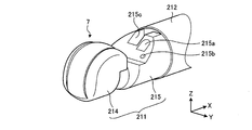
- FIG. 2 is a perspective view schematically showing the tip configuration of the insertion portion of the ultrasonic endoscope according to Embodiment 1 of the present invention.
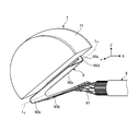
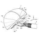
- FIG. 3 is a perspective view schematically showing an internal configuration of a distal end portion in the ultrasonic endoscope according to the first embodiment of the present invention.
- FIG. 4 is a diagram for explaining the configuration of the ultrasonic transducer shown in FIG.
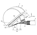
- FIG. 5 is a view for explaining a bending mode of the relay substrate shown in FIG.
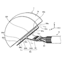
- FIG. 6 is a view for explaining a bending mode of the relay substrate shown in FIG.
- FIG. 5 is a view for explaining a bending mode of the relay substrate shown in FIG.
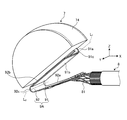
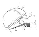
- FIG. 7 is a perspective view schematically showing an internal configuration of an ultrasonic wave functional unit in the ultrasonic endoscope according to the second embodiment of the present invention.
- FIG. 8 is an exploded perspective view schematically showing an internal configuration of an ultrasonic wave functional unit in the ultrasonic endoscope according to the second embodiment of the present invention.
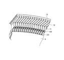
- FIG. 9 is a view schematically showing a configuration of a part of an ultrasonic wave functional unit in an ultrasonic endoscope according to Embodiment 2 of the present invention.
- FIG. 10 is a view schematically showing a configuration of a part of the ultrasonic wave functional unit in the ultrasonic endoscope according to the second embodiment of the present invention.
- FIG. 11 is a perspective view schematically showing an internal configuration of an ultrasonic wave functional unit in the ultrasonic endoscope according to the third embodiment of the present invention.
- FIG. 12 is a view schematically showing a configuration of a part of an ultrasonic wave functional unit in an ultrasonic endoscope according to Embodiment 3 of the present invention.
- FIG. 13 is a perspective view schematically showing an internal configuration of an ultrasonic wave functional unit in an ultrasonic endoscope according to a fourth embodiment of the present invention.
- FIG. 14 is a view schematically showing a configuration of a part of an ultrasonic wave functional unit in an ultrasonic endoscope according to a fourth embodiment of the present invention.
- FIG. 12 is a view schematically showing a configuration of a part of an ultrasonic wave functional unit in an ultrasonic endoscope according to Embodiment 3 of the present invention.
- FIG. 13 is a perspective view schematically showing an internal configuration of an ultrasonic wave functional unit in an ultrasonic endo
- FIG. 15 is a perspective view schematically showing an internal configuration of an ultrasonic wave functional unit in an ultrasonic endoscope according to a modification of the fourth embodiment of the present invention.
- FIG. 16 is a perspective view schematically showing an internal configuration of an ultrasonic wave functional unit in an ultrasonic endoscope according to a modification of the fourth embodiment of the present invention.
- FIG. 17 is a perspective view schematically showing an internal configuration of an ultrasonic wave functional unit in the ultrasonic endoscope according to the fifth embodiment of the present invention.
- FIG. 18 is a diagram schematically showing a part of an ultrasonic wave functional unit in an ultrasonic endoscope according to a fifth embodiment of the present invention.
- FIG. 19 is a view schematically showing a configuration of a part of an ultrasonic wave functional unit in an ultrasonic endoscope according to a fifth embodiment of the present invention.
- FIG. 20 is a view schematically showing a part of an ultrasonic wave functional unit in an ultrasonic endoscope according to a sixth embodiment of the present invention.
- FIG. 21 is an enlarged view of a region R of FIG.
- FIG. 22 is a cross-sectional view taken along line AA shown in FIG.
- FIG. 23 is a perspective view schematically showing an internal configuration of an ultrasonic wave functional unit in an ultrasonic endoscope according to another embodiment of the present invention.
- FIG. 1 is a view schematically showing an endoscope system according to a first embodiment of the present invention.
- the endoscope system 1 is a system that performs ultrasound diagnosis in a subject such as a person using an ultrasound endoscope. As shown in FIG. 1, the endoscope system 1 includes an ultrasound endoscope 2, an ultrasound observation device 3, an endoscope observation device 4, a display device 5, and a light source device 6.
- the ultrasonic endoscope 2 converts an electrical pulse signal received from the ultrasonic observation apparatus 3 into an ultrasonic pulse (acoustic pulse) by an ultrasonic transducer provided at the tip of the ultrasonic endoscope 2 and irradiates the object with an object. At the same time, the ultrasonic echo reflected by the subject is converted into an electrical echo signal represented by a voltage change and output.
- the ultrasound endoscope 2 has an imaging optical system and an imaging element, and is inserted into a digestive tract (esophagus, stomach, duodenum, large intestine) or a respiratory organ (trachea, bronchi) of a subject, It is possible to do either imaging of the respiratory system.
- the ultrasound endoscope 2 has a light guide for guiding illumination light to be irradiated to a subject at the time of imaging.
- the light guide has a distal end portion reaching the distal end of the insertion portion of the ultrasonic endoscope 2 into the subject, while the proximal end portion is connected to the light source device 6 that generates illumination light.
- the ultrasound endoscope 2 transmits ultrasound to the digestive tract and surrounding organs of the respiratory organ (pancreas, gallbladder, bile duct, biliary tract, lymph node, mediastinal organ, blood vessel, etc.) Receive ultrasound waves reflected by organs.
- organs of the respiratory organ pancreas, gallbladder, bile duct, biliary tract, lymph node, mediastinal organ, blood vessel, etc.
- the ultrasound endoscope 2 includes an insertion unit 21, an operation unit 22, a universal cord 23, and a connector 24.
- the insertion unit 21 is a portion to be inserted into the subject.
- the insertion portion 21 is provided on the distal end side, and has a rigid distal end portion 211 including the ultrasonic transducer 7 and a bending portion 212 connected to the proximal end side of the distal end portion 211 and capable of bending. And a flexible tube portion 213 connected to the proximal end side of the bending portion 212 and having flexibility.
- the bending portion 212 can bend the longitudinal axis of the distal end portion 211 in two different directions.
- the curved portion 212 can be bent on, for example, the XY plane shown in FIG. 1 to change the direction of the tip end portion 211, and can be bent on an XZ plane orthogonal to the XY plane to change the direction of the tip end portion 211 It is.
- the ultrasonic transducer 7 is a convex type in which a plurality of piezoelectric elements are provided in an array and electronic scanning is performed by electronically switching the piezoelectric elements involved in transmission and reception or delaying transmission and reception of each piezoelectric element. Ultrasonic transducer. The configuration of the ultrasonic transducer 7 will be described later.
- FIG. 2 is a perspective view schematically showing the tip configuration of the insertion portion of the ultrasonic endoscope according to the first embodiment.
- the distal end portion 211 includes an ultrasonic transducer module 214 for holding the ultrasonic transducer 7, an objective lens 215a which forms part of an imaging optical system and takes in light from the outside, an imaging device, And an endoscope module 215 having an illumination lens 215 b that condenses the illumination light and emits it to the outside.
- the endoscope module 215 is formed with a treatment tool projecting port 215c which communicates with the treatment tool insertion path formed in the insertion portion 21 and causes the treatment tool to protrude from the tip end of the insertion portion 21.
- the vicinity of the end connected to the treatment instrument projection port 215c is inclined with respect to the longitudinal axis of the insertion portion 21, and the treatment instrument protrudes in the direction inclined from the treatment instrument projection port 215c with respect to the longitudinal axis It is provided to do.
- the longitudinal axis referred to here is an axis along the longitudinal direction of the insertion portion 21.
- the axial direction changes depending on each position in the bending portion 212 and the flexible tube portion 213, but in the rigid tip portion 211, the longitudinal axis is an axis forming a straight line.
- the operation unit 22 is a portion that is connected to the proximal end side of the insertion unit 21 and receives various operations from a user such as a doctor. As shown in FIG. 1, the operation unit 22 includes a bending knob 221 for bending the bending portion 212 and a plurality of operation members 222 for performing various operations. Further, a treatment tool insertion port 223 is formed in the operation portion 22 so as to communicate with the treatment tool insertion path and for inserting the treatment tool in the treatment tool insertion path.
- the universal cord 23 is a cable that extends from the operation unit 22 and is provided with a plurality of signal cables for transmitting various signals, and an optical fiber for transmitting illumination light supplied from the light source device 6.
- the connector 24 is provided at the tip of the universal cord 23.
- the connector 24 includes first to third connector portions 241 to 243 to which the ultrasonic cable 31, the video cable 41, and the optical fiber cable 61 are respectively connected.
- the ultrasound observation apparatus 3 is electrically connected to the ultrasound endoscope 2 via the ultrasound cable 31 (FIG. 1), and outputs a pulse signal to the ultrasound endoscope 2 via the ultrasound cable 31. And an echo signal from the ultrasound endoscope 2. Then, the ultrasound observation apparatus 3 performs predetermined processing on the echo signal to generate ultrasound image data.
- the endoscopic observation device 4 is electrically connected to the ultrasonic endoscope 2 via the video cable 41 (see FIG. 1), and receives an image signal from the ultrasonic endoscope 2 via the video cable 41. Do. Then, the endoscope observation device 4 performs predetermined processing on the image signal to generate endoscope image data.
- the display device 5 is configured using a liquid crystal or organic EL (Electro Luminescence), a projector, a CRT (Cathode Ray Tube), or the like, and an ultrasound image generated by the ultrasound observation device 3 or the endoscopic observation device 4 The endoscopic image etc. which were produced
- a liquid crystal or organic EL Electro Luminescence
- a projector a projector
- a CRT Cathode Ray Tube
- the light source device 6 is connected to the ultrasonic endoscope 2 via the optical fiber cable 61 (see FIG. 1), and illumination light for illuminating the inside of the subject via the optical fiber cable 61 is transmitted to the ultrasonic endoscope 2. Supply.
- FIG. 3 is a perspective view schematically showing an internal configuration of the distal end portion 211 in the ultrasonic endoscope according to the first embodiment.
- FIG. 4 is a diagram for explaining the configuration of the ultrasonic transducer 7 shown in FIG.
- the ultrasonic transducer 7 is a convex-type ultrasonic transducer as shown in FIG. 2 and is a one-dimensional array (1D array) in which a plurality of piezoelectric elements 71 are arranged in a line. It explains as a certain thing.
- the plurality of piezoelectric elements 71 are arranged to be curved along the curved outer surface of the ultrasonic transducer 7 and include the longitudinal axis. And transmit and receive ultrasonic waves on a plane (e.g., XZ plane) parallel to the longitudinal axis.
- a plane e.g., XZ plane
- the ultrasonic transducer 7 has a prismatic shape, and a plurality of piezoelectric elements 71 aligned in the longitudinal direction, and a first sound provided on the outer surface side of the ultrasonic transducer 7 with respect to the piezoelectric element 71.
- an acoustic lens 74 (see FIG. 3) provided on the side.
- a backing material (not shown) is provided on the side opposite to the side in contact with the first acoustic matching layer 72 of the piezoelectric element 71.
- the backing material attenuates unnecessary ultrasonic vibrations generated by the operation of the piezoelectric element 71.
- the backing material is formed using a material having a high damping rate, for example, an epoxy resin in which a filler such as alumina or zirconia is dispersed, or a rubber in which the filler described above is dispersed.
- the piezoelectric element 71 converts an electrical pulse signal into an acoustic pulse and irradiates the object with the object, and converts an ultrasonic echo reflected by the object into an electrical echo signal representing the voltage change. Output.
- the piezoelectric element 71 is connected to an ultrasonic cable 8 electrically connected to the ultrasonic cable 31 (see FIG. 3).
- the ultrasonic cable 8 has a plurality of coaxial wires 81. Each coaxial line 81 is electrically connected to the corresponding piezoelectric element 71 via a relay substrate 9 described later.
- FIG. 3 shows a simplified configuration for the purpose of explanation, the actual coaxial lines are provided in accordance with the number of piezoelectric elements 71.
- the first acoustic matching layer 72 and the second acoustic matching layer 73 have an acoustic impedance of the piezoelectric element 71 and an acoustic impedance of the observation target in order to efficiently transmit sound (ultrasound) between the piezoelectric element 71 and the observation target. And match.
- the first acoustic matching layer 72 and the second acoustic matching layer 73 are made of different materials.
- the first embodiment is described as having the two acoustic matching layers (the first acoustic matching layer 72 and the second acoustic matching layer 73), it is possible to use one layer according to the characteristics of the piezoelectric element 71 and the observation target. It is good, and it is good also as three or more layers.
- the acoustic lens 74 covers the outer surfaces of the first acoustic matching layer 72 and the second acoustic matching layer 73.
- the acoustic lens 74 forms the outer surface of the ultrasonic transducer 7.
- the acoustic lens 74 is formed using silicone, polymethylpentene, epoxy resin, polyether imide, or the like, and has a function of squeezing an ultrasonic wave by forming a convex or concave shape on one surface, and the second acoustic matching layer 73
- the ultrasound that has passed through is emitted to the outside, or the ultrasound echo from the outside is captured.
- the acoustic lens 74 can be optionally provided, and the acoustic lens 74 may not be provided.
- the ultrasonic transducer 7 having the above-described configuration vibrates the piezoelectric element 71 in response to the input of the pulse signal, and thereby the observation object is oversized through the first acoustic matching layer 72, the second acoustic matching layer 73, and the acoustic lens 74. Irradiate sound waves.
- a backing material attenuates unnecessary ultrasonic vibration from the piezoelectric element 71 on the side opposite to the side where the first acoustic matching layer 72, the second acoustic matching layer 73, and the acoustic lens 74 are provided. I am doing it.
- the ultrasonic wave reflected from the observation target is transmitted to the piezoelectric element 71 through the acoustic lens 74, the second acoustic matching layer 73, and the first acoustic matching layer 72.
- the piezoelectric element 71 vibrates by the transmitted ultrasonic wave, and the piezoelectric element 71 converts the vibration into an electrical echo signal and outputs the echo signal to the ultrasonic observation device 3.
- the ultrasonic transducer module 214 forms a part of a path electrically connecting the ultrasonic transducer 7, the ultrasonic transducer 7 (the ultrasonic transducer module 214), and the ultrasonic observation device 3.
- the relay substrate 9 relays the electrical connection with the coaxial line 81 (see FIG. 3).
- the relay substrate 9 is electrically connected to the connection portion of the piezoelectric element 71 by the solder 102 at the end of the piezoelectric element 71 opposite to the surface transmitting / receiving the ultrasonic wave, as shown in FIG. It is done.
- the relay substrate 9 is configured using a flexible printed circuit (FPC), and can be deformed according to an external load.
- FPC flexible printed circuit
- the relay substrate 9 is electrically connected to a plurality of coaxial lines 81 passing through the inside of the ultrasonic cable 8.
- the relay substrate 9 is obtained by providing a wiring pattern on a belt-like base formed of polyimide.
- the surface having the largest area in the relay substrate 9 is referred to as a “main surface”.
- the relay substrate 9 has a transmission path of an electrical signal between the first portion 90a extending from the ultrasonic transducer 7, the second portion 90b connected to the ultrasonic cable 8, and the first portion 90a to the second portion 90b. And a third portion 90c.
- the relay substrate 9 is formed using a single substrate.
- the third portion 90c is bent in a direction different from the bending portion 90d (first bending portion) continuous with the first portion 90a and the bending portion 90d, and is a bending portion 90e (second bending portion) continuous with the second portion 90b. And.
- FIG. 5 is a view for explaining a bending mode of the relay substrate shown in FIG. 3, and is an enlarged view of a bending portion 90e.
- FIG. 6 is a view for explaining the bending mode of the relay substrate shown in FIG. 3 when the relay substrate 9 is viewed from the direction orthogonal to the main surface of the third portion 90c located between the bending portions 90d and 90e. It is a top view.
- the bent portions 90 d and 90 e are bent in directions orthogonal to each other. Specifically, a straight line L 1 (first straight line) extending along the ridge line of the bending end of the bending portion 90 d and a straight line L 2 (second straight line extending along the ridge line of the bending end of the bending portion 90 e are orthogonal to each other in a plan view seen from the direction orthogonal to the main surface extending between the bent portions 90d and 90e. In the first embodiment, the main surface extending between the bent portions 90d and 90e is the main surface of the third portion 90c. Linear L 2, as shown in FIGS. 5 and 6, extends along the edge of the bent end portion of the bent portion 90e.
- the bending end here is the end of the part which protrudes by bending.
- the ridge line is a line extending in the width direction of the relay substrate 9 along the protruding end.
- the width direction is a direction extending along the main surface of the relay substrate and is a direction (short direction) orthogonal to the longitudinal direction. Note that extend Similarly, along the ridge line of the bent end portion of the bent portion 90d also linear L 1.
- the normal vector of the tangent plane (first tangent plane) in contact with bend 90d and the normal vector of the tangent plane (second tangent plane) in contact with bend 90e are components.
- a vector in the same direction as the stress vector of the stress generated by the bending of the bending portion 212 is represented. That is, with respect to the stress caused by the bending of the bending portion 212, the bending portion 90d is curved with respect to the stress perpendicular to the tangent plane (first tangent plane) in contact with the bending portion 90d, and the tangent plane (second The stress applied to the relay substrate 9 is reduced by bending the bending portion 90 e with respect to the stress perpendicular to the tangent plane).
- the relay substrate 9 according to the first embodiment is configured to be bent in two different directions by the bending portion 90 d and the bending portion 90 e.
- the bending portion 212 when the bending portion 212 is bent, even if it is bent on the XY plane or in the case of being bent on the XZ plane, they are mutually bent in the bending direction according to the curve.
- By bending two different bending portions bending portions 90d and 90e), it is possible to relieve the stress caused by the bending.
- the stress applied to the connection portion of the flexible substrate can be relaxed even when the curved portion that can be bent in two directions is curved in any direction. By relaxing the stress caused by the bending, the disconnection of the coaxial line can be suppressed, and the reliability of the ultrasonic endoscope can be improved.
- FIG. 7 is a perspective view schematically showing an internal configuration of an ultrasonic wave functional unit in the ultrasonic endoscope according to the second embodiment of the present invention.
- the relay board 9 is described as being integrally formed in the first embodiment described above, in the second embodiment, the relay board is formed by connecting two members.
- the relay substrate 9A shown in FIG. 7 has a distal end side substrate 91 connected to the ultrasonic transducer 7, and a proximal end side substrate 92 connected to the distal end side substrate 91 while being connected to the ultrasonic cable 8.
- FIG. 8 is an exploded perspective view schematically showing an internal configuration of an ultrasonic wave functional unit in the ultrasonic endoscope according to the second embodiment of the present invention.
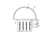
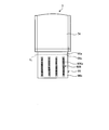
- FIG. 9 is a view schematically showing a configuration of a part of the ultrasonic wave functional unit in the ultrasonic endoscope according to Embodiment 2 of the present invention, in which the curved portion of the distal end side substrate 91 is stretched.
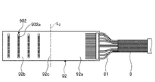
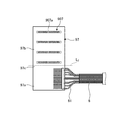
- FIG. 10 is a view schematically showing a configuration of a part of the ultrasonic wave functional unit in the ultrasonic endoscope according to the second embodiment of the present invention, in which the curved portion of the proximal substrate 92 is stretched.
- FIG. 9 is a view schematically showing a configuration of a part of the ultrasonic wave functional unit in the ultrasonic endoscope according to Embodiment 2 of the present invention, in which the curved portion of the distal end side substrate 91 is stretched.
- FIG. 10 is a view schematically showing a configuration of a part of
- the tip side second portion 91 b has a bending portion 91 c (first bending portion) continuous with the tip side first portion 91 a.
- the base end side substrate 92 is connected to the base end side first portion 92a connected to the ultrasonic cable 8 and the tip end side substrate 91, and the main surface is connected to the base end side first portion 92a via the tip side second portion 91b. And a proximal second portion 92b facing each other.
- the bent portions 91c and 92c are bent in directions orthogonal to each other. Specifically, a straight line L 1 (first straight line) extending along the ridge line of the bending end of the bending portion 91 c and a straight line L 2 (second straight line extending along the ridge line of the bending end of the bending portion 92 c Are orthogonal to each other in a plan view seen from the direction orthogonal to the main surface extending between the bent portions 91c and 92c. In the second embodiment, the main surface extending between the bent portions 91c and 92c is the main surface of the distal end side second portion 91b or the proximal end second portion 92b.
- the straight lines L 1 and L 2 are also shown in the developed views shown in FIGS. 9 and 10 for the sake of explanation, the straight lines L 1 and L 2 are actually ridge lines generated when the bent portion is bent. In line with
- An electrode group 901 including a plurality of electrodes 901 a for connecting to the base end side substrate 92 is formed on the front end side second portion 91 b of the front end side substrate 91.
- an electrode group 902 composed of a plurality of electrodes 902a respectively connected to the electrodes 901a formed on the front end side second portion 91b of the front end side substrate 91 is formed on the base end side substrate 92.
- the relay substrate 9A has a structure bent in directions different from each other by connecting the corresponding electrodes 901a and 902a in the front end side substrate 91 and the base end side substrate 92. Solder or a conductive adhesive is used to connect the electrodes 901a and 902a.
- the relay substrate 9A according to the second embodiment has a configuration in which it is bent in two different directions by the bending portions 91c and 92c in a state in which the distal end side substrate 91 and the proximal end side substrate 92 are connected.
- the bending portion 212 when the bending portion 212 is curved, even if it is curved on the XY plane or in the case of being curved on the XZ plane, they are mutually bent in the bending direction according to the curvature.
- By bending two different bending portions (bending portions 91c and 92c), it is possible to relieve the stress caused by the bending.
- the stress applied to the connection portion of the flexible substrate can be relaxed even when the curved portion that can be bent in two directions is curved in any direction.
- the ultrasonic cable 8 is connected by connecting the distal substrate 91 and the proximal substrate 92. Wiring can be performed on the proximal substrate 92 collectively. As a result, the connection of the ultrasonic cable 8 to the base substrate 92 can be made more easily.
- FIG. 11 is a perspective view schematically showing an internal configuration of an ultrasonic wave functional unit in the ultrasonic endoscope according to the third embodiment of the present invention.
- FIG. 12 is a view schematically showing a configuration of a part of the ultrasonic wave functional unit in the ultrasonic endoscope according to the third embodiment of the present invention, and a curved portion of the first substrate 93A and the second substrate 93B. It is a figure which shows the structure which extended.
- the 11 includes a distal end side substrate 91 connected to the ultrasonic transducer 7, and a first substrate 93A and a second substrate 93B respectively connected to the ultrasonic cable 8 (hereinafter collectively referred to as the proximal side substrate 93). And the distal end side substrate 91 and the proximal end side substrate 93 are connected.
- the first substrate 93A is connected to a part of coaxial lines 81 among the plurality of coaxial lines 81 of the ultrasonic cable 8.
- the second substrate 93 ⁇ / b> B is connected to a coaxial line 81 different from the coaxial line 81 connected to the first substrate 93 ⁇ / b> A among the plurality of coaxial lines 81 included in the ultrasonic cable 8.
- the first substrate 93A is connected to the proximal end first portion 93a connected to the ultrasonic cable 8 and the distal end side substrate 91, and the proximal end second portion whose main surface faces the main surface of the proximal first portion 93a And a portion 93b.
- the proximal second portion 93b is bent in a direction different from that of the bent portion 91c, and has a bent portion 93c (second bent portion) continuous with the proximal first portion 93a.
- An electrode group 903A composed of a plurality of electrodes 903a respectively connected to a part of the plurality of electrodes 901a formed on the tip end side second portion 91b of the tip end side substrate 91 is formed on the base end side second portion 93b. It is done.
- the second substrate 93B is connected to the proximal end first portion 93d connected to the ultrasonic cable 8 and the distal end side substrate 91, and the proximal end second portion whose main surface faces the main surface of the proximal first portion 93d And a portion 93e.
- the proximal second portion 93e has a bent portion 93f (second bent portion) bent in a direction different from that of the bent portion 91c and continuing to the proximal first portion 93d.
- An electrode group 903B including a plurality of electrodes 903b connected to a part of the plurality of electrodes 901a formed on the base end side second portion 91b of the front end side substrate 91 is provided in the base end side second portion 93e. It is formed.
- the first substrate 93A and the second substrate 93B are disposed on the side surfaces facing each other with respect to the tip side substrate 91, and the corresponding electrode 901a is connected to the electrodes 903a or 903b.
- the bent ends are bent in opposite directions.
- the bent portions 91c and the bent portions 93c and 93f are bent in directions orthogonal to each other.
- a straight line L 22 (second straight line) extending along the ridge line of the bending end of the bending portion 93 f is a direction orthogonal to the main surface extending between the bending portion 91 c and the bending portions 93 c and 93 f They are orthogonal to each other in plan view seen from the perspective.
- the main surface extending between the bending portion 91c and the bending portions 93c and 93f is the main surface of the distal end side second portion 91b or the proximal end second portion 93b or 93e.
- the relay substrate 9B according to the third embodiment has a configuration in which it is bent in two different directions by the bending portions 91c, 93c, and 93f in a state where the base end side substrate 93 is connected to the tip end side substrate 91. .
- the bending portion 212 when the bending portion 212 is curved, the bending portion on the XY plane or the bending portion on the XZ plane has a plurality of bending portions according to the bending.
- By bending (the bending portions 91c, 93c, 93f), it is possible to relieve the stress caused by the bending.
- the stress applied to the connection portion of the flexible substrate can be relaxed even when the curved portion that can be bent in two directions is curved in any direction.
- FIG. 13 is a perspective view schematically showing an internal configuration of an ultrasonic wave functional unit in an ultrasonic endoscope according to a fourth embodiment of the present invention.
- FIG. 14 is a view schematically showing a configuration of a part of the ultrasonic wave functional unit in the ultrasonic endoscope according to the fourth embodiment of the present invention, in which the curved portion of the distal end side substrate 94 is stretched.
- FIG. The relay substrate 9C shown in FIG. 13 has a distal end side substrate 94 connected to the ultrasonic transducer 7 and a proximal end side substrate 93 connected to the ultrasonic cable 8 respectively.
- the base end side substrate 93 (the first substrate 93A and the second substrate 93B) is the same as that of the third embodiment described above, and thus the description thereof is omitted.
- the tip side substrate 94 includes a tip side first portion 94 a extending from the ultrasonic transducer 7, a tip side second portion 94 b having a main surface perpendicular to the main surface of the tip side first portion 94 a, and a tip side third And a portion 94c.
- the distal end side second portion 94 b and the distal end side third portion 94 c are separated via the slit 94 f.
- the distal side second portion 94 b has a bent portion 94 d (first curved portion) continuous with the distal side first portion 94 a.
- the distal end side third portion 94 c has a bending portion 94 e (first bending portion) continuous with the distal end side first portion 94 a.
- the bending portions 94 d and 94 e are bent in opposite directions to each other at bending end portions.
- a straight line L 11 (first straight line) extending along the ridge line of the bending end of the bending portion 94 c and a straight line L 12 (first straight line extending along the ridge line of the bending end of the bending portion 94 d ),
- a straight line L 21 (second straight line) extending along the ridge line of the bending end of the bending portion 93 c, and a straight line L 22 (second straight line) extending along the ridge line of the bending end of the bending portion 93 f
- the main surface extending between the bending portions 94c and 94d and the bending portions 93c and 93f is the main surface of the distal second portion 94b or 94c or the proximal second portion 93b or 93e. is there. It is to be parallel to the straight line L 11 and the straight line L 12, it is parallel to the straight line L 21 and the straight line L 22.
- An electrode group 904A including a plurality of electrodes 904a respectively connected to the electrodes 903a of the electrode group 903A formed on the second substrate 93A on the main surface facing the ultrasonic transducer 7 in the tip side second portion 94b It is formed.
- the relay substrate 9C arranges the first substrate 93A and the second substrate 93B with respect to the front end side substrate 94 via the slits 94f, and connects the corresponding electrodes 904a and 903a, the electrodes 904b and the electrodes 903b. Thus, they are bent in different directions.
- the relay substrate 9C according to the fourth embodiment has a configuration in which it is bent in two different directions by bending portions 93c, 93f, 94d, and 94e in a state in which the distal end side substrate 94 and the base end side substrate 93 are connected.
- the bending portion 212 when the bending portion 212 is curved, the bending portion on the XY plane or the bending portion on the XZ plane has a plurality of bending portions according to the bending.
- By bending (the bending portions 93c, 93f, 94d, 94e), it is possible to relieve the stress caused by the bending.
- the stress applied to the connection portion of the flexible substrate can be relaxed even when the curved portion that can be bent in two directions is curved in any direction.
- FIGS. 15 and 16 are perspective views schematically showing an internal configuration of an ultrasonic wave functional unit in an ultrasonic endoscope according to a modification of the fourth embodiment of the present invention.
- FIG. 16 is a view seen from the Y direction shown in FIG.
- the relay substrate 9D shown in the figure includes a distal end side substrate 95 connected to the ultrasonic transducer 7 and a proximal end side substrate 93 connected to the ultrasonic cable 8 respectively.
- the base end side substrate 93 (the first substrate 93A and the second substrate 93B) is the same as that of the third embodiment described above, and thus the description thereof is omitted.
- the tip side substrate 95 includes a tip side first portion 95a extending from the ultrasonic transducer 7, a tip side second portion 95b having a main surface perpendicular to the main surface of the tip side first portion 95a, and a tip side third And a portion 95c.
- the distal end side second portion 95 b and the distal end side third portion 95 c are separated via the slit 95 f.
- the distal side second portion 95 b has a bent portion 95 d (first curved portion) continuous with the distal side first portion 95 a.
- the distal third portion 95c has a bending portion 95e (first bending portion) continuous with the distal first portion 95a.
- the bending parts of the bending parts 95 d and 95 e are bent in opposite directions.
- the bending portions 95 d and 95 e and the bending portions 93 c and 93 f are bent in directions orthogonal to each other.
- a straight line L 11 first straight line
- a straight line L 12 first straight line extending along the ridge line of the bending end of the bending portion 95 e
- a straight line L 21 extending along the ridge line of the bending end of the bending portion 93 c and a straight line L 22 extending along the ridge line of the bending end of the bending portion 93 f, the bending portions 95 d and 95 e, and the bending portion
- They are orthogonal to each other in a plan view seen from the direction orthogonal to the main surface extending between 93c and 93f.
- the main surface extending between the bent portions 95d and 95e and the bent portions 93c and 93f is the main surface of the distal second portion 95b or 95c or the proximal second portion 93b or 93e. Note that it is parallel to the straight line L 11 and the straight line L 12.
- An electrode group (shown in the figure, in the front end side second portion 95b, a plurality of electrodes respectively connected to the electrodes 903a of the electrode group 903A formed on the first substrate 93A on the main surface facing the ultrasonic transducer 7). Is formed.
- an electrode group (a plurality of electrodes connected with each electrode 903b of the electrode group 903B formed on the second substrate 93B (shown in FIG. Is formed.
- the tip side substrate 95 is, for example, a shape in which the electrode group 904B of the tip side third portion 94c of the tip side substrate 94 described above is formed on the main surface on the opposite side and bent in the opposite direction.
- the relay substrate 9D has a structure bent in directions different from each other by connecting the corresponding electrodes by reversing the bending directions of the first substrate 93A and the second substrate 93B with respect to the tip side substrate 95. It is eggplant.
- the relay substrate 9D has a configuration in which it is bent in two different directions by the bending portions 93c, 93f, 95d, and 95e in a state where the distal end side substrate 95 and the proximal end side substrate 93 are connected.
- a plurality of bent portions (bent By bending the portions 93c, 93f, 95d, 95e), it is possible to relieve the stress caused by the bending.
- the stress applied to the connection portion of the flexible substrate can be relaxed even when the curved portion that can be bent in two directions is curved in any direction.
- FIG. 17 is a perspective view schematically showing an internal configuration of an ultrasonic wave functional unit in the ultrasonic endoscope according to the fifth embodiment of the present invention.
- FIG. 18 is a view schematically showing a configuration of a part of the ultrasonic wave function unit in the ultrasonic endoscope according to the fifth embodiment of the present invention, in which the curved portion of the first substrate 96 is stretched.
- FIG. 19 is a view schematically showing a configuration of a part of an ultrasonic wave functional unit in an ultrasonic endoscope according to a fifth embodiment of the present invention, in which a curved portion of the second substrate 97 is stretched.
- FIG. A relay substrate 9E shown in FIG. 17 has a distal end side substrate 96 connected to the ultrasonic transducer 7 and a proximal end side substrate 97 connected to the ultrasonic cable 8.
- the distal end side substrate 96 includes a distal end side first portion 96 a extending from the ultrasonic transducer 7 and a distal end side second portion 96 b extending in a direction different from the distal end side first portion 96 a and coupled to the proximal end substrate 97.
- the tip side first portion 96a has a main surface orthogonal to a plane (XZ plane in FIG. 17) parallel to a scan plane by ultrasonic waves.
- the front end side substrate 96 is arranged to be rotated by 90 ° with respect to the front end side substrate 91 of the second embodiment described above.
- the distal second portion 96 b has a bent portion 96 c (first curved portion) connecting the distal first portion 96 a and the distal second portion 96 b.
- the base end side substrate 97 is connected to the base end side first portion 97a connected to the ultrasonic cable 8 and the tip end side substrate 96, and the main surface is connected to the base end side first portion 97a via the tip side second portion 96b. And a proximal second portion 97b facing each other.
- the proximal second portion 97 b has a bent portion 97 c (second bent portion) bent in a direction different from that of the bent portion 96 c and continuous with the proximal first portion 97 a.
- the bending portion 96c and the bending portion 97c are bent in directions orthogonal to each other.
- a straight line L 1 (first straight line) extending along the ridge line of the bending end of the bending portion 96 c and a straight line L 2 (second straight line extending along the ridge line of the bending end of the bending portion 97 c are orthogonal to each other in a plan view seen from the direction orthogonal to the main surface extending between the bent portions 96c and 97c.
- the main surface extending between the bent portions 96c and 97c is the main surface of the distal second portion 9b or the proximal second portion 97b.
- An electrode group 906 including a plurality of electrodes 906a for connection to the base end side substrate 97 is formed on the front end side second portion 96b of the front end side substrate 96 (see FIG. 18).
- an electrode group 907 consisting of a plurality of electrodes 907a respectively connected to the electrodes 906a formed on the front end side second portion 96b of the front end side substrate 96 is formed (FIG. 19). reference).
- the relay substrate 9E has a structure bent in directions different from each other by connecting the corresponding electrodes 906a and 907a in the distal end side substrate 96 and the proximal end side substrate 97.
- the relay substrate 9E has a shape in which the bending mode of the front end side substrate 91 and the base end side two substrates 92 of the relay substrate 9A described above is reversed.
- FIG. 20 is a diagram schematically showing a part of the structure of an ultrasonic wave functional unit in an ultrasonic endoscope according to Embodiment 6 of the present invention, and is a diagram of the first substrate 91A according to Embodiment 6. It is a figure which shows the structure which extended the curved part.
- FIG. 21 is an enlarged view of a region R of FIG.
- FIG. 22 is a cross-sectional view taken along line AA shown in FIG.
- the overall shape of the tip side substrate 91A in the ultrasonic transducer module according to the sixth embodiment is the same as the tip side substrate 91 shown in FIG.
- the configuration of the electrodes in the tip side substrate 91A is different from that of the tip side substrate 91, so only the configuration of the electrodes will be described here.
- the tip side substrate 91A has a tip side first portion 91a, a tip side second portion 91b, and a bending portion 91c.
- An electrode group 910 including a plurality of electrodes 910 a for connecting to the base end side substrate 92 is formed in the tip end side second portion 91 b.
- a slit 911 is formed between the electrodes 910a adjacent to each other in the arrangement direction, and a space 912 is formed on the back surface of the electrode 910a.
- Each electrode 910a has a flying lead structure by the space formed by the slits 911 and the space 912, and the movable range by bending of the base end side substrate 92 is compared to the case where the slits 911 and the space 912 are not provided. growing.
- the electrode 910a has a flying lead structure, the stress received from the proximal substrate 92 can be absorbed by the electrode 910a.
- the flying lead structure is described as being formed on the electrode of the distal second portion 91b of the distal side substrate 91A, but the proximal second portion 92b of the proximal substrate 92 is described. It may be formed in the electrode of.
- the rigidity of the bent portion is set by providing a notch in the bent portion of each substrate or making the thickness of the bent portion thinner than the thickness of the other portion. It may be smaller than the part and may be easily deformed.
- a portion other than the bent portion (the tip end portion and / or the proximal end portion) may be formed using a hard material, and the bent portion may be configured to be more positively deformed against stress.
- FIG. 23 is a perspective view schematically showing an internal configuration of an ultrasonic wave functional unit in an ultrasonic endoscope according to another embodiment of the present invention.
- the third portion 90c has the bending portions 90f and 90g having a smaller thickness than the thicknesses of the first portion 90a and the second portion 90b. May be
- a piezoelectric element is described as an example of emitting ultrasonic waves and converting ultrasonic waves incident from the outside into echo signals.
- the present invention is not limited to this.
- a device manufactured using Micro Electro Mechanical Systems
- C-MUT Capacitive Micromachined Ultrasonic Transducers
- P-MUT Pielectric Micromachined Ultrasonic Transducers
- an ultrasonic endoscope it may be applied to a small diameter ultrasonic probe which mechanically rotates and scans an oscillator without an optical system.
- the ultrasound probe is usually inserted into the biliary tract, bile duct, pancreatic duct, trachea, bronchus, urethra, ureter and used to observe the surrounding organs (pancreas, lung, prostate, bladder, lymph nodes, etc.).
- the ultrasonic transducer may be a linear transducer, a radial transducer or a convex transducer.
- its scan area is rectangular (rectangular, square)
- the ultrasonic transducer is a radial transducer or convex transducer
- its scan area is sectoral or annular. It is eggplant.
- the ultrasound endoscope may mechanically scan the ultrasound transducers, or a plurality of elements are provided in an array as the ultrasound transducers, and the elements involved in transmission and reception are switched electronically. Alternatively, scanning may be performed electronically by delaying transmission and reception of each element.
- an extracorporeal ultrasonic probe may be applied which irradiates ultrasonic waves from the body surface of the subject.
- Extracorporeal ultrasound probes are usually used to observe abdominal organs (liver, gallbladder, bladder), breast (especially mammary gland), thyroid.
- an ultrasonic endoscope having an ultrasonic transducer at its tip has been described as an example, but an endoscope having no ultrasonic transducer, for example, an endoscope module It is also possible to apply to an endoscope provided with only 215 at the tip.
- an endoscope the configurations of the first to sixth embodiments described above can be applied in a configuration provided with a relay substrate connected to an imaging device and a cable extending from the relay substrate to the connector.
- the ultrasonic endoscope in which the insertion portion 21 includes the flexible tube portion 213 has been described as an example, but instead of the flexible tube portion 213, a hard tube portion is used. It is possible to apply even if it is an endoscope provided with the insertion part which it has, ie, a rigid endoscope.
- the endoscope according to the present invention is useful for alleviating the stress applied to the connection portion of the flexible substrate even if the bending portion which can be bent in two directions is bent in any direction. is there.
Landscapes
- Health & Medical Sciences (AREA)
- Life Sciences & Earth Sciences (AREA)
- Physics & Mathematics (AREA)
- Surgery (AREA)
- Molecular Biology (AREA)
- Veterinary Medicine (AREA)
- Pathology (AREA)
- Radiology & Medical Imaging (AREA)
- Engineering & Computer Science (AREA)
- Biomedical Technology (AREA)
- Heart & Thoracic Surgery (AREA)
- Medical Informatics (AREA)
- Biophysics (AREA)
- Nuclear Medicine, Radiotherapy & Molecular Imaging (AREA)
- Animal Behavior & Ethology (AREA)
- General Health & Medical Sciences (AREA)
- Public Health (AREA)
- Gynecology & Obstetrics (AREA)
- Optics & Photonics (AREA)
- Astronomy & Astrophysics (AREA)
- General Physics & Mathematics (AREA)
- Ultra Sonic Daignosis Equipment (AREA)
- Endoscopes (AREA)
- Instruments For Viewing The Inside Of Hollow Bodies (AREA)
Abstract
本発明にかかる内視鏡は、画像データを生成するための電気信号を生成する素子を有する先端部と、先端部の基端側に接続され、互いに直交する二方向に湾曲可能な湾曲部と、湾曲部を挿通し、前記電気信号の伝送を行う複数の同軸線と、配線、主面が屈曲する第1の屈曲部、および、第1の屈曲部と直交する方向に主面が屈曲する第2の屈曲部を有し、配線の一端を素子に電気的に接続し、他端を同軸線に接続して、素子から同軸線へ電気信号を伝送する中継基板と、を備える。
Description
本発明は、被検体内に挿入される挿入部を備えた内視鏡に関する。
従来、医療分野においては、患者等の被検体の臓器を観察する際に内視鏡システムが用いられている。内視鏡システムは、例えば先端に撮像素子が設けられ、被検体内に挿入される挿入部を有する内視鏡と、挿入部の基端側にケーブルを介して接続され、撮像素子が生成した撮像信号に応じた体内画像の画像処理を行って、体内画像を表示部等に表示させる処理装置と、を備える。挿入部は、撮像素子が設けられる先端部の基端側に設けられ、湾曲自在な湾曲部を有する。
内視鏡では、撮像素子と信号ケーブルとが、屈曲可能なフレキシブル基板を介して接続される(例えば、特許文献1を参照)。特許文献1によれば、外部から加わる荷重に対してフレキシブル基板が屈曲することによって、その荷重による、撮像素子とフレキシブル基板との接続部に加わる応力を緩和することができる。特許文献1が開示する内視鏡は、フレキシブル基板の屈曲する方向に沿って湾曲部が湾曲した際、この湾曲により生じる応力を緩和することが可能である。
ところで、互いに直交する二方向に湾曲可能な内視鏡も知られている。この内視鏡に特許文献1の構成を適用すると、フレキシブル基板が一方向にしか屈曲しないため、撮像素子とフレキシブル基板の接続部に加わる応力を緩和することができない場合があった。
本発明は、上記に鑑みてなされたものであって、二方向に湾曲可能な湾曲部が、いずれの方向に湾曲した場合であってもフレキシブル基板の接続部に加わる応力を緩和することができる内視鏡を提供することを目的とする。
上述した課題を解決し、目的を達成するために、本発明に係る内視鏡は、画像データを生成するための電気信号を生成する素子を有する先端部と、前記先端部の基端側に接続され、互いに直交する二方向に湾曲可能な湾曲部と、前記湾曲部を挿通し、前記電気信号の伝送を行う複数の同軸線と、配線、主面が屈曲する第1の屈曲部、および、前記第1の屈曲部と直交する方向に主面が屈曲する第2の屈曲部を有し、前記配線の一端を前記素子に電気的に接続し、他端を前記同軸線に接続して、前記素子から前記同軸線へ前記電気信号を伝送する中継基板と、を備える、ことを特徴とする。
また、本発明に係る内視鏡は、上記発明において、前記中継基板は、一枚の基板を用いて形成されることを特徴とする。
また、本発明に係る内視鏡は、上記発明において、前記中継基板は、前記第1の屈曲部を有し、前記素子に接続する先端側基板と、前記第2の屈曲部を有し、前記先端側基板に接続するとともに、前記複数の同軸線に接続する基端側基板と、を備えることを特徴とする。
また、本発明に係る内視鏡は、上記発明において、前記基端側基板は、一端が前記先端側基板に接続するとともに、他端が、前記複数の同軸線のうちの一部の同軸線に接続する第1基端側基板と、一端が前記先端側基板に接続するとともに、他端が、前記複数の同軸線のうち、前記第1基端側基板に接続する同軸線とは異なる同軸線に接続する第2基端側基板と、を有することを特徴とする。
また、本発明に係る内視鏡は、上記発明において、前記先端側基板は、前記素子に接続する先端側第1部分と、前記基端側基板にそれぞれ接続する先端側第2部分および先端側第3部分とを有し、前記先端側第2部分および先端側第3部分は、前記先端側第1部分に連なる前記第2の屈曲部をそれぞれ有することを特徴とする。
また、本発明に係る内視鏡は、上記発明において、前記第1基端側基板は、前記先端側第2部分の前記先端側第3部分側と反対側から該先端側第2部分に接続し、前記第2基端側基板は、前記先端側第3部分の前記先端側第2部分側と反対側から該先端側第3部分に接続することを特徴とする。
また、本発明に係る内視鏡は、上記発明において、前記第1基端側基板は、前記先端側第2部分の前記先端側第3部分側から該先端側第2部分に接続し、前記第2基端側基板は、前記先端側第3部分の前記先端側第2部分側から該先端側第3部分に接続することを特徴とする。
また、本発明に係る内視鏡は、上記発明において、前記先端側基板と前記基端側基板とは、対応する電極同士を接触させることによって接続し、少なくとも一方の基板に形成される電極は、フライングリード構造をなしていることを特徴とする。
また、本発明に係る内視鏡は、上記発明において、前記第1および第2の屈曲部は、厚さが、他の部分の厚さと比して薄いことを特徴とする。
また、本発明に係る内視鏡は、上記発明において、前記中継基板は、屈曲自在なフレキシブル基板を用いて形成されることを特徴とする。
また、本発明に係る内視鏡は、上記発明において、前記素子は、超音波振動子を構成する複数の圧電素子であることを特徴とする。
また、本発明に係る内視鏡は、上記発明において、前記超音波振動子は、コンベックス型であることを特徴とする。
また、本発明に係る内視鏡は、上記発明において、前記湾曲部は、前記超音波振動子が送信する超音波による走査面と平行な平面に沿った第1の湾曲方向と、前記走査面に対して垂直な平面に沿った第2の湾曲方向とに湾曲可能であることを特徴とする。
本発明によれば、二方向に湾曲可能な湾曲部が、いずれの方向に湾曲した場合であってもフレキシブル基板の接続部に加わる応力を緩和することができるという効果を奏する。
以下に、図面を参照して、本発明を実施するための形態(以下、実施の形態)について説明する。なお、以下に説明する実施の形態によって本発明が限定されるものではない。さらに、図面の記載において、同一の部分には同一の符号を付している。
(実施の形態1)
図1は、本発明の実施の形態1に係る内視鏡システムを模式的に示す図である。内視鏡システム1は、超音波内視鏡を用いて人等の被検体内の超音波診断を行うシステムである。この内視鏡システム1は、図1に示すように、超音波内視鏡2と、超音波観測装置3と、内視鏡観察装置4と、表示装置5と、光源装置6とを備える。
図1は、本発明の実施の形態1に係る内視鏡システムを模式的に示す図である。内視鏡システム1は、超音波内視鏡を用いて人等の被検体内の超音波診断を行うシステムである。この内視鏡システム1は、図1に示すように、超音波内視鏡2と、超音波観測装置3と、内視鏡観察装置4と、表示装置5と、光源装置6とを備える。
超音波内視鏡2は、その先端部に設けられた超音波振動子によって、超音波観測装置3から受信した電気的なパルス信号を超音波パルス(音響パルス)に変換して被検体へ照射するとともに、被検体で反射された超音波エコーを電圧変化で表現する電気的なエコー信号に変換して出力する。
超音波内視鏡2は、撮像光学系および撮像素子を有しており、被検体の消化管(食道、胃、十二指腸、大腸)、または呼吸器(気管、気管支)へ挿入され、消化管や、呼吸器のいずれかの撮像を行うことが可能である。超音波内視鏡2は、撮像時に被検体へ照射する照明光を導くライトガイドを有する。このライトガイドは、先端部が超音波内視鏡2の被検体への挿入部の先端まで達している一方、基端部が照明光を発生する光源装置6に接続されている。また、超音波内視鏡2は、消化管や、呼吸器の周囲臓器(膵臓、胆嚢、胆管、胆道、リンパ節、縦隔臓器、血管等)に対して、超音波を送信し、該周辺臓器で反射した超音波を受信する。
超音波内視鏡2は、図1に示すように、挿入部21と、操作部22と、ユニバーサルコード23と、コネクタ24とを備える。挿入部21は、被検体内に挿入される部分である。この挿入部21は、図1に示すように、先端側に設けられ、超音波振動子7を含む硬性の先端部211と、先端部211の基端側に連結され湾曲可能とする湾曲部212と、湾曲部212の基端側に連結され可撓性を有する可撓管部213とを備える。ここで、挿入部21の内部には、具体的な図示は省略したが、光源装置6から供給された照明光を伝送するライトガイド、後述する信号線(同軸線81)を含む、各種信号を伝送する複数の信号線が引き回されているとともに、処置具を挿通するための処置具用挿通路などが形成されている。湾曲部212は、先端部211の長手軸を互いに異なる二方向に湾曲可能である。湾曲部212は、例えば図1に示すXY平面上で湾曲して先端部211の向きを変更可能であるとともに、このXY平面と直交するXZ平面上で湾曲して先端部211の向きを変更可能である。
超音波振動子7は、複数の圧電素子をアレイ状に設け、送受信にかかわる圧電素子を電子的に切り替えたり、各圧電素子の送受信に遅延をかけたりすることで、電子的に走査させるコンベックス型の超音波振動子である。超音波振動子7の構成については、後述する。
図2は、本実施の形態1に係る超音波内視鏡の挿入部の先端構成を模式的に示す斜視図である。図2に示すように、先端部211は、超音波振動子7を保持する超音波振動子モジュール214と、撮像光学系の一部をなし、外部からの光を取り込む対物レンズ215a、撮像素子、および、照明光を集光して外部に出射する照明レンズ215bを有する内視鏡モジュール215と、を備える。内視鏡モジュール215には、挿入部21内に形成された処置具用挿通路に連通し、挿入部21の先端から処置具を突出させる処置具突出口215cが形成されている。処置具用挿通路は、処置具突出口215cに連なる端部近傍が、挿入部21の長手軸に対して傾斜し、処置具が処置具突出口215cから長手軸に対して傾斜した方向に突出するように設けられている。ここでいう長手軸とは、挿入部21の長手方向に沿った軸である。湾曲部212や可撓管部213では各位置によって軸方向が変化するが、硬性の先端部211では、長手軸は、一定した直線をなす軸である。
図1に戻り、操作部22は、挿入部21の基端側に連結され、医師等のユーザからの各種操作を受け付ける部分である。この操作部22は、図1に示すように、湾曲部212を湾曲操作するための湾曲ノブ221と、各種操作を行うための複数の操作部材222とを備える。また、操作部22には、処置具用挿通路に連通し、当該処置具用挿通路に処置具を挿通するための処置具挿入口223が形成されている。
ユニバーサルコード23は、操作部22から延在し、各種信号を伝送する複数の信号ケーブル、および光源装置6から供給された照明光を伝送する光ファイバ等が配設されたケーブルである。
コネクタ24は、ユニバーサルコード23の先端に設けられている。そして、コネクタ24は、超音波ケーブル31、ビデオケーブル41、および光ファイバケーブル61がそれぞれ接続される第1~第3コネクタ部241~243を備える。
超音波観測装置3は、超音波ケーブル31(図1)を介して超音波内視鏡2に電気的に接続し、超音波ケーブル31を介して超音波内視鏡2にパルス信号を出力するとともに超音波内視鏡2からエコー信号を入力する。そして、超音波観測装置3は、当該エコー信号に所定の処理を施して超音波画像データを生成する。
内視鏡観察装置4は、ビデオケーブル41(図1参照)を介して超音波内視鏡2に電気的に接続し、ビデオケーブル41を介して超音波内視鏡2からの画像信号を入力する。そして、内視鏡観察装置4は、当該画像信号に所定の処理を施して内視鏡画像データを生成する。
表示装置5は、液晶または有機EL(Electro Luminescence)、プロジェクタ、CRT(Cathode Ray Tube)などを用いて構成され、超音波観測装置3にて生成された超音波画像や、内視鏡観察装置4にて生成された内視鏡画像等を表示する。
光源装置6は、光ファイバケーブル61(図1参照)を介して超音波内視鏡2に接続し、光ファイバケーブル61を介して被検体内を照明する照明光を超音波内視鏡2に供給する。
続いて、挿入部21の先端に設けられた超音波振動子7の構成を、図3、4を参照して説明する。図3は、本実施の形態1に係る超音波内視鏡における先端部211の内部構成を模式的に示す斜視図である。図4は、図3に示す超音波振動子7の構成を説明する図である。本実施の形態1では、超音波振動子7が、図2に示すようなコンベックス型の超音波振動子であって、複数の圧電素子71が一列に配列された一次元アレイ(1Dアレイ)であるものとして説明する。換言すれば、本実施の形態1に係る超音波振動子7では、複数の圧電素子71が、当該超音波振動子7の曲面をなす外表面に沿って湾曲して配列され、長手軸を含み、かつ該長手軸と平行な面(例えばXZ平面)上で超音波を送受信する。
超音波振動子7は、角柱状をなし、長手方向を揃えて並べられてなる複数の圧電素子71と、圧電素子71に対し、当該超音波振動子7の外表面側に設けられる第1音響整合層72と、第1音響整合層72の圧電素子71と接する側と反対側に設けられる第2音響整合層73と、第2音響整合層73の第1音響整合層72と接する側と反対側に設けられる音響レンズ74(図3参照)とを有する。圧電素子71の第1音響整合層72と接する側と反対側には、図示しないバッキング材が設けられている。バッキング材は、圧電素子71の動作によって生じる不要な超音波振動を減衰させる。バッキング材は、減衰率の大きい材料、例えば、アルミナやジルコニア等のフィラーを分散させたエポキシ樹脂や、上述したフィラーを分散したゴムを用いて形成される。
図4において、圧電素子71は、電気的なパルス信号を音響パルスに変換して被検体へ照射するとともに、被検体で反射された超音波エコーを電圧変化で表現する電気的なエコー信号に変換して出力する。圧電素子71は、超音波ケーブル31と電気的に接続する超音波ケーブル8に接続する(図3参照)。超音波ケーブル8は、複数の同軸線81を有している。各同軸線81は、後述する中継基板9を介して対応する圧電素子71と電気的に接続している。なお、図3では、説明のために簡略化した構成を図示しているが、実際の同軸線は、圧電素子71の数に応じて設けられている。
第1音響整合層72および第2音響整合層73は、圧電素子71と観測対象との間で音(超音波)を効率よく透過させるために、圧電素子71の音響インピーダンスと観測対象の音響インピーダンスとをマッチングさせる。第1音響整合層72および第2音響整合層73は、互いに異なる材料からなる。なお、本実施の形態1では、二つの音響整合層(第1音響整合層72および第2音響整合層73)を有するものとして説明するが、圧電素子71と観測対象との特性により一層としてもよいし、三層以上としてもよい。
音響レンズ74は、第1音響整合層72、第2音響整合層73の外表面を被覆する。音響レンズ74は、超音波振動子7の外表面をなしている。音響レンズ74は、シリコーン、ポリメチルペンテン、エポキシ樹脂、ポリエーテルイミドなどを用いて形成され、一方の面が凸状または凹状をなして超音波を絞る機能を有し、第2音響整合層73を通過した超音波を外部に出射する、または外部からの超音波エコーを取り込む。音響レンズ74については、任意に設けることができ、当該音響レンズ74を有しない構成であってもよい。
以上の構成を有する超音波振動子7は、パルス信号の入力によって圧電素子71が振動することで、第1音響整合層72、第2音響整合層73および音響レンズ74を介して観測対象に超音波を照射する。この際、圧電素子71において、第1音響整合層72、第2音響整合層73および音響レンズ74の配設側と反対側は、バッキング材により、圧電素子71からの不要な超音波振動を減衰させている。また、観測対象から反射された超音波は、音響レンズ74、第2音響整合層73および第1音響整合層72を介して圧電素子71に伝えられる。伝達された超音波により圧電素子71が振動し、圧電素子71が該振動を電気的なエコー信号に変換して超音波観測装置3に出力する。
超音波振動子モジュール214は、超音波振動子7と、当該超音波振動子7(超音波振動子モジュール214)と超音波観測装置3とを電気的に接続する経路の一部をなす複数の同軸線81(図3参照)との間の電気的な接続を中継する中継基板9を備える。中継基板9は、図4に示すように、圧電素子71の一端側であって、超音波を送受信する表面と反対側において、リード101が半田102によって圧電素子71の接続部と電気的に接続されている。中継基板9は、フレキシブル基板(Flexible Printed Circuits:FPC)を用いて構成され、外部からの荷重に応じて変形可能である。中継基板9は、超音波ケーブル8の内部を挿通する複数の同軸線81と電気的に接続している。中継基板9は、ポリイミドを用いて形成される帯状の基材に配線パターンを設けてなる。以下、中継基板9における最も広い面積を有する面を「主面」という。
中継基板9は、超音波振動子7から延びる第1部分90aと、超音波ケーブル8と接続する第2部分90bと、第1部分90aから第2部分90bとの間の電気信号の伝送経路をなす第3部分90cと、を有する。中継基板9は、一枚の基板を用いて形成される。
第3部分90cは、第1部分90aに連なる屈曲部90d(第1の屈曲部)と、屈曲部90dとは異なる方向に屈曲し、第2部分90bに連なる屈曲部90e(第2の屈曲部)と、を有する。
図5は、図3に示す中継基板の屈曲態様を説明する図であって、屈曲部90eの拡大図である。図6は、図3に示す中継基板の屈曲態様を説明する図であって、屈曲部90d、90eの間に位置する第3部分90cの主面と直交する方向から中継基板9をみたときの平面図である。
屈曲部90d、90eは、互いに直交する方向に屈曲している。具体的には、屈曲部90dの屈曲端部の稜線に沿って延びる直線L1(第1の直線)と、屈曲部90eの屈曲端部の稜線に沿って延びる直線L2(第2の直線)とが、屈曲部90d、90eの間に延びる主面と直交する方向からみた平面視において、互いに直交している。本実施の形態1において、屈曲部90d、90eの間に延びる主面は、第3部分90cの主面である。直線L2は、図5、6に示すように、屈曲部90eの屈曲端部の稜線に沿って延びている。ここでいう屈曲端部は、屈曲により突出した部分のその端部である。稜線は、その突出端部に沿って、中継基板9の幅方向に延びる線である。本明細書において、幅方向は、中継基板の主面に沿って延びる方向であって、長手方向と直交する方向(短手方向)とする。なお、直線L1についても同様に、屈曲部90dの屈曲端部の稜線に沿って延びている。
このような屈曲部90d、90eにおいて、屈曲部90dに接する接平面(第1接平面)の法線ベクトルと、屈曲部90eに接する接平面(第2接平面)の法線ベクトルとを成分として、湾曲部212の湾曲により生じる応力の応力ベクトルと同じ方向のベクトルが表現される。すなわち、湾曲部212の湾曲により生じる応力に対して、屈曲部90dに接する接平面(第1接平面)に垂直な応力については屈曲部90dが湾曲し、屈曲部90eに接する接平面(第2接平面)に垂直な応力については屈曲部90eが湾曲することで、中継基板9への応力を低減する。
以上説明したように、本実施の形態1に係る中継基板9は、屈曲部90dおよび屈曲部90eにより、異なる二つの方向にそれぞれ屈曲した構成をなしている。本実施の形態1によれば、湾曲部212が湾曲した際、XY平面上で湾曲した場合であっても、XZ平面上で湾曲した場合であっても、その湾曲に応じて互いに屈曲方向の異なる二つの屈曲部(屈曲部90d、90e)が屈曲することによって、湾曲により生じる応力を緩和することができる。このように、本実施の形態1では、二方向に湾曲可能な湾曲部が、いずれの方向に湾曲した場合であってもフレキシブル基板の接続部に加わる応力を緩和することができる。湾曲により生じる応力を緩和することによって、同軸線の断線などが抑制され、超音波内視鏡の信頼性を向上することができる。
(実施の形態2)
図7は、本発明の実施の形態2に係る超音波内視鏡における超音波機能部の内部構成を模式的に示す斜視図である。上述した実施の形態1では、中継基板9が一体的に形成されているものとして説明したが、本実施の形態2では、中継基板が、二つの部材を連結してなる。図7に示す中継基板9Aは、超音波振動子7に接続する先端側基板91と、超音波ケーブル8に接続するとともに、先端側基板91に接続する基端側基板92とを有する。
図7は、本発明の実施の形態2に係る超音波内視鏡における超音波機能部の内部構成を模式的に示す斜視図である。上述した実施の形態1では、中継基板9が一体的に形成されているものとして説明したが、本実施の形態2では、中継基板が、二つの部材を連結してなる。図7に示す中継基板9Aは、超音波振動子7に接続する先端側基板91と、超音波ケーブル8に接続するとともに、先端側基板91に接続する基端側基板92とを有する。
図8は、本発明の実施の形態2に係る超音波内視鏡における超音波機能部の内部構成を模式的に示す分解斜視図である。図9は、本発明の実施の形態2に係る超音波内視鏡における超音波機能部の一部の構成を模式的に示す図であって、先端側基板91の湾曲部分を引き延ばした構成を示す図である。図10は、本発明の実施の形態2に係る超音波内視鏡における超音波機能部の一部の構成を模式的に示す図であって、基端側基板92の湾曲部分を引き延ばした構成を示す図である。
先端側基板91は、超音波振動子7から延びる先端側第1部分91aと、先端側第1部分91aの主面に対して垂直な主面を有する先端側第2部分91bと、を有する。先端側第1部分91aは、超音波による走査面と平行な平面(図7のXZ平面)に平行な主面を有する。
先端側第2部分91bは、先端側第1部分91aに連なる屈曲部91c(第1の屈曲部)を有する。
基端側基板92は、超音波ケーブル8と接続する基端側第1部分92aと、先端側基板91と接続し、主面が先端側第2部分91bを介して基端側第1部分92aと向かい合う基端側第2部分92bと、を有する。
基端側第2部分92bは、屈曲部91cとは異なる方向に屈曲し、基端側第1部分92aに連なる屈曲部92c(第2の屈曲部)を有する。
屈曲部91c、92cは、互いに直交する方向に屈曲している。具体的には、屈曲部91cの屈曲端部の稜線に沿って延びる直線L1(第1の直線)と、屈曲部92cの屈曲端部の稜線に沿って延びる直線L2(第2の直線)とが、屈曲部91c、92cの間に延びる主面と直交する方向からみた平面視において、互いに直交している。本実施の形態2において、屈曲部91c、92cの間に延びる主面は、先端側第2部分91bまたは基端側第2部分92bの主面である。なお、説明のため、図9、10に示す展開図においても、直線L1、L2を示しているが、この直線L1、L2は、実際には屈曲部が屈曲した際に生じる稜線に沿ったものである。
先端側基板91の先端側第2部分91bには、基端側基板92と接続するための複数の電極901aからなる電極群901が形成されている。他方、基端側基板92には、先端側基板91の先端側第2部分91bに形成されている各電極901aとそれぞれ接続する複数の電極902aからなる電極群902が形成されている。中継基板9Aは、先端側基板91と基端側基板92とにおいて対応する電極901a、902a同士を接続することによって、互いに異なる方向に屈曲した構造をなす。電極901a、902a同士の接続には、半田や、導電性の接着剤が用いられる。
本実施の形態2に係る中継基板9Aは、先端側基板91と基端側基板92とを連結した状態において、屈曲部91c、92cにより、異なる二つの方向にそれぞれ屈曲した構成をなしている。本実施の形態2によれば、湾曲部212が湾曲した際、XY平面上で湾曲した場合であっても、XZ平面上で湾曲した場合であっても、その湾曲に応じて互いに屈曲方向の異なる二つの屈曲部(屈曲部91c、92c)が屈曲することによって、湾曲により生じる応力を緩和することができる。このように、本実施の形態2では、二方向に湾曲可能な湾曲部が、いずれの方向に湾曲した場合であってもフレキシブル基板の接続部に加わる応力を緩和することができる。
また、本実施の形態2によれば、基端側基板92に超音波ケーブル8を接続した後に先端側基板91と基端側基板92とを接続するようにすることによって、超音波ケーブル8を一括して基端側基板92に配線することができる。これにより、超音波ケーブル8の基端側基板92への接続を、一段と容易に行うことが可能となる。
(実施の形態3)
図11は、本発明の実施の形態3に係る超音波内視鏡における超音波機能部の内部構成を模式的に示す斜視図である。図12は、本発明の実施の形態3に係る超音波内視鏡における超音波機能部の一部の構成を模式的に示す図であって、第1基板93Aおよび第2基板93Bの湾曲部分を引き延ばした構成を示す図である。図11に示す中継基板9Bは、超音波振動子7に接続する先端側基板91と、超音波ケーブル8にそれぞれ接続する第1基板93Aおよび第2基板93B(以下、まとめて基端側基板93ということもある)とを有し、先端側基板91と基端側基板93とを連結してなる。
図11は、本発明の実施の形態3に係る超音波内視鏡における超音波機能部の内部構成を模式的に示す斜視図である。図12は、本発明の実施の形態3に係る超音波内視鏡における超音波機能部の一部の構成を模式的に示す図であって、第1基板93Aおよび第2基板93Bの湾曲部分を引き延ばした構成を示す図である。図11に示す中継基板9Bは、超音波振動子7に接続する先端側基板91と、超音波ケーブル8にそれぞれ接続する第1基板93Aおよび第2基板93B(以下、まとめて基端側基板93ということもある)とを有し、先端側基板91と基端側基板93とを連結してなる。
第1基板93Aは、超音波ケーブル8が有する複数の同軸線81のうちの一部の同軸線81と接続する。
第2基板93Bは、超音波ケーブル8が有する複数の同軸線81のうち、第1基板93Aに接続する同軸線81とは異なる同軸線81と接続する。
第2基板93Bは、超音波ケーブル8が有する複数の同軸線81のうち、第1基板93Aに接続する同軸線81とは異なる同軸線81と接続する。
第1基板93Aは、超音波ケーブル8と接続する基端側第1部分93aと、先端側基板91と接続し、主面が基端側第1部分93aの主面と向かい合う基端側第2部分93bと、を有する。
基端側第2部分93bは、屈曲部91cとは異なる方向に屈曲し、基端側第1部分93aに連なる屈曲部93c(第2の屈曲部)を有する。基端側第2部分93bには、先端側基板91の先端側第2部分91bに形成されている複数の電極901aのうちの一部とそれぞれ接続する複数の電極903aからなる電極群903Aが形成されている。
第2基板93Bは、超音波ケーブル8と接続する基端側第1部分93dと、先端側基板91と接続し、主面が基端側第1部分93dの主面と向かい合う基端側第2部分93eと、を有する。
基端側第2部分93eは、屈曲部91cとは異なる方向に屈曲し、基端側第1部分93dに連なる屈曲部93f(第2の屈曲部)を有する。基端側第2部分93eには、先端側基板91の基端側第2部分91bに形成されている複数の電極901aのうちの一部とそれぞれ接続する複数の電極903bからなる電極群903Bが形成されている。
中継基板9Bは、先端側基板91に対し、第1基板93Aと第2基板93Bとを、対向する側面側にそれぞれ配設し、対応する電極901aと、電極903aまたは903b同士を接続することによって、屈曲端部が互いに反対方向に屈曲した構造をなす。
この際、屈曲部91cと、屈曲部93c、93fは、互いに直交する方向に屈曲している。具体的には、屈曲部91cの屈曲端部の稜線に沿って延びる直線L1(第1の直線)と、屈曲部93cの屈曲端部の稜線に沿って延びる直線L21(第2の直線)、および、屈曲部93fの屈曲端部の稜線に沿って延びる直線L22(第2の直線)とが、屈曲部91cと、屈曲部93c、93fとの間に延びる主面と直交する方向からみた平面視において、互いに直交している。本実施の形態3において、屈曲部91cと、屈曲部93c、93fとの間に延びる主面は、先端側第2部分91bまたは基端側第2部分93bもしくは93eの主面である。
本実施の形態3に係る中継基板9Bは、先端側基板91に基端側基板93を連結した状態において、屈曲部91c、93c、93fにより、異なる二つの方向にそれぞれ屈曲した構成をなしている。本実施の形態3によれば、湾曲部212が湾曲した際、XY平面上で湾曲した場合であっても、XZ平面上で湾曲した場合であっても、その湾曲に応じて複数の屈曲部(屈曲部91c、93c、93f)が屈曲することによって、湾曲により生じる応力を緩和することができる。このように、本実施の形態3では、二方向に湾曲可能な湾曲部が、いずれの方向に湾曲した場合であってもフレキシブル基板の接続部に加わる応力を緩和することができる。
(実施の形態4)
図13は、本発明の実施の形態4に係る超音波内視鏡における超音波機能部の内部構成を模式的に示す斜視図である。図14は、本発明の実施の形態4に係る超音波内視鏡における超音波機能部の一部の構成を模式的に示す図であって、先端側基板94の湾曲部分を引き延ばした構成を示す図である。図13に示す中継基板9Cは、超音波振動子7に接続する先端側基板94と、超音波ケーブル8にそれぞれ接続する基端側基板93とを有する。基端側基板93(第1基板93Aおよび第2基板93B)は、上述した実施の形態3と同様であるため、説明を省略する。
図13は、本発明の実施の形態4に係る超音波内視鏡における超音波機能部の内部構成を模式的に示す斜視図である。図14は、本発明の実施の形態4に係る超音波内視鏡における超音波機能部の一部の構成を模式的に示す図であって、先端側基板94の湾曲部分を引き延ばした構成を示す図である。図13に示す中継基板9Cは、超音波振動子7に接続する先端側基板94と、超音波ケーブル8にそれぞれ接続する基端側基板93とを有する。基端側基板93(第1基板93Aおよび第2基板93B)は、上述した実施の形態3と同様であるため、説明を省略する。
先端側基板94は、超音波振動子7から延びる先端側第1部分94aと、先端側第1部分94aの主面に対して垂直な主面を有する先端側第2部分94bおよび先端側第3部分94cと、を有する。先端側第2部分94bおよび先端側第3部分94cは、スリット94fを介して離間している。
先端側第2部分94bは、先端側第1部分94aに連なる屈曲部94d(第1の屈曲部)を有する。先端側第3部分94cは、先端側第1部分94aに連なる屈曲部94e(第1の屈曲部)を有する。屈曲部94d、94eは、屈曲端部が互いに反対方向に屈曲している。
この際、屈曲部94c、94dと、屈曲部93c、93fとは、互いに直交する方向に屈曲している。具体的には、屈曲部94cの屈曲端部の稜線に沿って延びる直線L11(第1の直線)および、屈曲部94dの屈曲端部の稜線に沿って延びる直線L12(第1の直線)と、屈曲部93cの屈曲端部の稜線に沿って延びる直線L21(第2の直線)、および、屈曲部93fの屈曲端部の稜線に沿って延びる直線L22(第2の直線)とが、屈曲部94c、94dと、屈曲部93c、93fとの間に延びる主面と直交する方向からみた平面視において、互いに直交している。本実施の形態4において、屈曲部94c、94dと、屈曲部93c、93fとの間に延びる主面は、先端側第2部分94bもしくは94cまたは基端側第2部分93bもしくは93eの主面である。なお、直線L11と直線L12とは平行であり、直線L21と直線L22とは平行である。
先端側第2部分94bには、超音波振動子7と向かい合う主面において、第2基板93Aに形成されている電極群903Aの各電極903aとそれぞれ接続する複数の電極904aからなる電極群904Aが形成されている。
先端側第3部分94cには、超音波振動子7と向かい合う主面において、第2基板93Bに形成されている電極群903Bの各電極903bとそれぞれ接続する複数の電極904bからなる電極群904Bが形成されている。
中継基板9Cは、先端側基板94に対し、第1基板93Aと第2基板93Bとを、スリット94fを介してそれぞれ配設し、対応する電極904aおよび電極903a、電極904bおよび電極903bを接続することによって、互いに異なる方向に屈曲した構造をなす。
本実施の形態4に係る中継基板9Cは、先端側基板94と、基端側基板93とを連結した状態において、屈曲部93c、93f、94d、94eにより、異なる二つの方向にそれぞれ屈曲した構成をなしている。本実施の形態4によれば、湾曲部212が湾曲した際、XY平面上で湾曲した場合であっても、XZ平面上で湾曲した場合であっても、その湾曲に応じて複数の屈曲部(屈曲部93c、93f、94d、94e)が屈曲することによって、湾曲により生じる応力を緩和することができる。このように、本実施の形態4では、二方向に湾曲可能な湾曲部が、いずれの方向に湾曲した場合であってもフレキシブル基板の接続部に加わる応力を緩和することができる。
(実施の形態4の変形例)
図15および図16は、本発明の実施の形態4の変形例に係る超音波内視鏡における超音波機能部の内部構成を模式的に示す斜視図である。図16は、図15に示すY方向からみた図である。同図に示す中継基板9Dは、超音波振動子7に接続する先端側基板95と、超音波ケーブル8にそれぞれ接続する基端側基板93と有する。基端側基板93(第1基板93Aおよび第2基板93B)は、上述した実施の形態3と同様であるため、説明を省略する。
図15および図16は、本発明の実施の形態4の変形例に係る超音波内視鏡における超音波機能部の内部構成を模式的に示す斜視図である。図16は、図15に示すY方向からみた図である。同図に示す中継基板9Dは、超音波振動子7に接続する先端側基板95と、超音波ケーブル8にそれぞれ接続する基端側基板93と有する。基端側基板93(第1基板93Aおよび第2基板93B)は、上述した実施の形態3と同様であるため、説明を省略する。
先端側基板95は、超音波振動子7から延びる先端側第1部分95aと、先端側第1部分95aの主面に対して垂直な主面を有する先端側第2部分95b及び先端側第3部分95cと、を有する。先端側第2部分95bおよび先端側第3部分95cは、スリット95fを介して離間している。
先端側第2部分95bは、先端側第1部分95aに連なる屈曲部95d(第1の屈曲部)を有する。先端側第3部分95cは、先端側第1部分95aに連なる屈曲部95e(第1の屈曲部)を有する。屈曲部95d、95eは、屈曲端部が互いに反対方向に屈曲している。
この際、屈曲部95d、95eと、屈曲部93c、93fとは、互いに直交する方向に屈曲している。具体的には、屈曲部95dの屈曲端部の稜線に沿って延びる直線L11(第1の直線)および、屈曲部95eの屈曲端部の稜線に沿って延びる直線L12(第1の直線)と、屈曲部93cの屈曲端部の稜線に沿って延びる直線L21、および、屈曲部93fの屈曲端部の稜線に沿って延びる直線L22とが、屈曲部95d、95eと、屈曲部93c、93fとの間に延びる主面と直交する方向からみた平面視において、互いに直交している。本変形例において、屈曲部95d、95eと、屈曲部93c、93fとの間に延びる主面は、先端側第2部分95bもしくは95cまたは基端側第2部分93bもしくは93eの主面である。なお、直線L11と直線L12とは平行である。
先端側第2部分95bには、超音波振動子7と向かい合う主面において、第1基板93Aに形成されている電極群903Aの各電極903aとそれぞれ接続する複数の電極からなる電極群(図示せず)が形成されている。
第3先端側部分95cには、超音波振動子7と向かい合う主面において、第2基板93Bに形成されている電極群903Bの各電極903bとそれぞれ接続する複数の電極からなる電極群(図示せず)が形成されている。
先端側基板95は、例えば、上述した先端側基板94の先端側第3部分94cの電極群904Bを反対側の主面に形成し、かつ反対方向に屈曲させた形状である。
中継基板9Dは、先端側基板95に対し、第1基板93Aと第2基板93Bとの互いの湾曲方向を逆にして、対応する電極同士を接続することによって、互いに異なる方向に屈曲した構造をなす。
本変形例に係る中継基板9Dは、先端側基板95および基端側基板93を連結した状態において、屈曲部93c、93f、95d、95eにより、異なる二つの方向にそれぞれ屈曲した構成をなしている。本変形例によれば、湾曲部212が湾曲した際、XY平面上で湾曲した場合であっても、XZ平面上で湾曲した場合であっても、その湾曲に応じて複数の屈曲部(屈曲部93c、93f、95d、95e)が屈曲することによって、湾曲により生じる応力を緩和することができる。このように、本変形例では、二方向に湾曲可能な湾曲部が、いずれの方向に湾曲した場合であってもフレキシブル基板の接続部に加わる応力を緩和することができる。
(実施の形態5)
図17は、本発明の実施の形態5に係る超音波内視鏡における超音波機能部の内部構成を模式的に示す斜視図である。図18は、本発明の実施の形態5に係る超音波内視鏡における超音波機能部の一部の構成を模式的に示す図であって、第1基板96の湾曲部分を引き延ばした構成を示す図である。図19は、本発明の実施の形態5に係る超音波内視鏡における超音波機能部の一部の構成を模式的に示す図であって、第2基板97の湾曲部分を引き延ばした構成を示す図である。図17に示す中継基板9Eは、超音波振動子7に接続する先端側基板96と、超音波ケーブル8に接続する基端側基板97とを有する。
図17は、本発明の実施の形態5に係る超音波内視鏡における超音波機能部の内部構成を模式的に示す斜視図である。図18は、本発明の実施の形態5に係る超音波内視鏡における超音波機能部の一部の構成を模式的に示す図であって、第1基板96の湾曲部分を引き延ばした構成を示す図である。図19は、本発明の実施の形態5に係る超音波内視鏡における超音波機能部の一部の構成を模式的に示す図であって、第2基板97の湾曲部分を引き延ばした構成を示す図である。図17に示す中継基板9Eは、超音波振動子7に接続する先端側基板96と、超音波ケーブル8に接続する基端側基板97とを有する。
先端側基板96は、超音波振動子7から延びる先端側第1部分96aと、先端側第1部分96aとは異なる方向に延び、基端側基板97と連結する先端側第2部分96bと、を有する。先端側第1部分96aは、超音波による走査面と平行な平面(図17のXZ平面)に対して直交する主面を有する。例えば、先端側基板96は、上述した実施の形態2の先端側基板91に対し、90°回転した配置となる。先端側第2部分96bは、先端側第1部分96aおよび先端側第2部分96bを接続する屈曲部96c(第1の屈曲部)を有する。
基端側基板97は、超音波ケーブル8と接続する基端側第1部分97aと、先端側基板96と接続し、主面が先端側第2部分96bを介して基端側第1部分97aと向かい合う基端側第2部分97bと、を有する。基端側第2部分97bは、屈曲部96cとは異なる方向に屈曲し、基端側第1部分97aに連なる屈曲部97c(第2の屈曲部)を有する。
この際、屈曲部96cと、屈曲部97cとは、互いに直交する方向に屈曲している。具体的には、屈曲部96cの屈曲端部の稜線に沿って延びる直線L1(第1の直線)と、屈曲部97cの屈曲端部の稜線に沿って延びる直線L2(第2の直線)とが、屈曲部96c、97cの間に延びる主面と直交する方向からみた平面視において、互いに直交している。本実施の形態5において、屈曲部96c、97cの間に延びる主面は、先端側第2部分9bまたは基端側第2部分97bの主面である。
先端側基板96の先端側第2部分96bには、基端側基板97と接続するための複数の電極906aからなる電極群906が形成されている(図18参照)。他方、基端側基板97には、先端側基板96の先端側第2部分96bに形成されている各電極906aとそれぞれ接続する複数の電極907aからなる電極群907が形成されている(図19参照)。中継基板9Eは、先端側基板96と基端側基板97とにおいて対応する電極906a、907a同士を接続することによって、互いに異なる方向に屈曲した構造をなす。中継基板9Eは、上述した中継基板9Aの先端側基板91と基端側2基板92との湾曲態様を逆にした形状をなしている。
本実施の形態5に係る中継基板9Eは、先端側基板96および基端側基板97を連結した状態において、屈曲部96c、97cにより、異なる二つの方向にそれぞれ屈曲した構成をなしている。本実施の形態5によれば、湾曲部212が湾曲した際、XY平面上で湾曲した場合であっても、XZ平面上で湾曲した場合であっても、その湾曲に応じて互いに屈曲方向の異なる二つの屈曲部(屈曲部96c、97c)が屈曲することによって、湾曲により生じる応力を緩和することができる。このように、本実施の形態5では、二方向に湾曲可能な湾曲部が、いずれの方向に湾曲した場合であってもフレキシブル基板の接続部に加わる応力を緩和することができる。
(実施の形態6)
図20は、本発明の実施の形態6に係る超音波内視鏡における超音波機能部の一部の構成を模式的に示す図であって、本実施の形態6に係る第1基板91Aの湾曲部分を引き延ばした構成を示す図である。図21は、図20の領域Rを拡大した図である。図22は、図21に示すA-A線断面図である。本実施の形態6に係る超音波振動子モジュールにおける先端側基板91Aの全体的な形状は、図6に示す先端側基板91と同じである。本実施の形態6は、先端側基板91Aにおける電極の構成が、先端側基板91と異なっているため、ここではその電極の構成についてのみ説明する。
図20は、本発明の実施の形態6に係る超音波内視鏡における超音波機能部の一部の構成を模式的に示す図であって、本実施の形態6に係る第1基板91Aの湾曲部分を引き延ばした構成を示す図である。図21は、図20の領域Rを拡大した図である。図22は、図21に示すA-A線断面図である。本実施の形態6に係る超音波振動子モジュールにおける先端側基板91Aの全体的な形状は、図6に示す先端側基板91と同じである。本実施の形態6は、先端側基板91Aにおける電極の構成が、先端側基板91と異なっているため、ここではその電極の構成についてのみ説明する。
先端側基板91Aは、先端側第1部分91a、先端側第2部分91bおよび屈曲部91cを有する。先端側第2部分91bには、基端側基板92と接続するための複数の電極910aからなる電極群910が形成されている。先端側第2部分91bには、長手方向を揃えて配列され、この配列方向で隣り合う電極910a間にスリット911が形成されるとともに、電極910aの裏面には、空間912が形成されている。各電極910aは、スリット911が形成する空間と、空間912とによってフライングリード構造をなし、基端側基板92の屈曲による可動範囲が、スリット911や空間912が設けられていない場合と比して大きくなる。本実施の形態6では、電極910aがフライングリード構造をなすことによって、基端側基板92から受ける応力を、電極910aによって吸収することができる。
なお、上述した実施の形態6では、フライングリード構造が先端側基板91Aの先端側第2部分91bの電極において形成されるものとして説明したが、基端側基板92の基端側第2部分92bの電極において形成されるようにしてもよい。
ここまで、本発明を実施するための形態を説明してきたが、本発明は上述した実施の形態および変形例によってのみ限定されるべきものではない。本発明は、以上説明した実施の形態および変形例には限定されず、特許請求の範囲に記載した技術的思想を逸脱しない範囲内において、様々な実施の形態を含みうるものである。また、実施の形態および変形例の構成を適宜組み合わせてもよい。
また、上述した実施の形態1~6において、各基板の屈曲部に切欠きを設けたり、屈曲部の厚さを他の部分の厚さよりも薄くしたりして、屈曲部の剛性を他の部分よりも小さくして、変形しやすくしてもよい。また、屈曲部以外の部分(先端側部分および/または基端側部分)を硬質の材料を用いて形成し、屈曲部が、応力に対してより積極的に変形するような構成としてもよい。
図23は、本発明のその他の実施の形態に係る超音波内視鏡における超音波機能部の内部構成を模式的に示す斜視図である。例えば、図23に示す中継基板9Fのように、第3部分90cが、第1部分90aおよび第2部分90bの厚さと比して、小さい厚さを有する屈曲部90f、90gを有するものであってもよい。
また、上述した実施の形態1~6では、超音波を出射するとともに、外部から入射した超音波をエコー信号に変換するものとして圧電素子を例に挙げて説明したが、これに限らず、MEMS(Micro Electro Mechanical Systems)を利用して製造した素子、例えばC-MUT(Capacitive Micromachined Ultrasonic Transducers)やP-MUT(Piezoelectric Micromachined Ultrasonic Transducers)であってもよい。
また、超音波内視鏡として、光学系がなく、振動子を機械的に回転させ走査する細径の超音波プローブに適用してもよい。超音波プローブは、通常、胆道、胆管、膵管、気管、気管支、尿道、尿管へ挿入され、その周囲臓器(膵臓、肺、前立腺、膀胱、リンパ節等)を観察する際に用いられる。
また、超音波振動子は、リニア振動子でもラジアル振動子でもコンベックス振動子でも構わない。超音波振動子がリニア振動子である場合、その走査領域は矩形(長方形、正方形)をなし、超音波振動子がラジアル振動子やコンベックス振動子である場合、その走査領域は扇形や円環状をなす。また、超音波内視鏡は、超音波振動子をメカ的に走査させるものであってもよいし、超音波振動子として複数の素子をアレイ状に設け、送受信にかかわる素子を電子的に切り替えたり、各素子の送受信に遅延をかけたりすることで、電子的に走査させるものであってもよい。
また、超音波内視鏡として、被検体の体表から超音波を照射する体外式超音波プローブを適用してもよい。体外式超音波プローブは、通常、腹部臓器(肝臓、胆嚢、膀胱)、乳房(特に乳腺)、甲状腺を観察する際に用いられる。
なお、上述した実施の形態1~6では、超音波振動子を先端に備えた超音波内視鏡を例に説明したが、超音波振動子を有しない内視鏡、例えば、内視鏡モジュール215のみを先端に備えた内視鏡においても適用することが可能である。内視鏡の場合、撮像素子に接続する中継基板と、中継基板からコネクタまで延びるケーブルとを備えた構成において、上述した実施の形態1~6の構成を適用することが可能である。
また、上述した実施の形態1~6では、挿入部21が可撓管部213を備えている超音波内視鏡を例に説明したが、可撓管部213に代えて硬質の管部を有する挿入部を備える内視鏡、すなわち硬性鏡であっても適用することが可能である。
以上のように、本発明にかかる内視鏡は、二方向に湾曲可能な湾曲部が、いずれの方向に湾曲した場合であってもフレキシブル基板の接続部に加わる応力を緩和するのに有用である。
1 内視鏡システム
2 超音波内視鏡
3 超音波観測装置
4 内視鏡観察装置
5 表示装置
6 光源装置
7 超音波振動子
8、31 超音波ケーブル
9、9A、9B、9C、9D、9E、9F 中継基板
21 挿入部
22 操作部
23 ユニバーサルコード
24 コネクタ
41 ビデオケーブル
61 光ファイバケーブル
71 圧電素子
72 第1音響整合層
73 第2音響整合層
74 音響レンズ
81 同軸線
90a 第1部分
90b 第2部分
90c 第3部分
90d、90e、90f、90g、91c、92c、93c、93f、94d、94e、95d、95e、96c、97c 屈曲部
91、94~96 先端側基板
92、93、97 基端側基板
93A 第1基板
93B 第2基板
91a、94a、95a、96a 先端側第1部分
91b、94b、95b、96b 先端側第2部分
92a、93a、93d、97a 基端側第1部分
92b、93b、93e、97b 基端側第2部分
94c、95c 先端側第3部分
211 先端部
212 湾曲部
213 可撓管部
214 超音波振動子モジュール
215 内視鏡モジュール
221 湾曲ノブ
222 操作部材
223 処置具挿入口
L1、L11、L12、L2、L21、L22 直線
2 超音波内視鏡
3 超音波観測装置
4 内視鏡観察装置
5 表示装置
6 光源装置
7 超音波振動子
8、31 超音波ケーブル
9、9A、9B、9C、9D、9E、9F 中継基板
21 挿入部
22 操作部
23 ユニバーサルコード
24 コネクタ
41 ビデオケーブル
61 光ファイバケーブル
71 圧電素子
72 第1音響整合層
73 第2音響整合層
74 音響レンズ
81 同軸線
90a 第1部分
90b 第2部分
90c 第3部分
90d、90e、90f、90g、91c、92c、93c、93f、94d、94e、95d、95e、96c、97c 屈曲部
91、94~96 先端側基板
92、93、97 基端側基板
93A 第1基板
93B 第2基板
91a、94a、95a、96a 先端側第1部分
91b、94b、95b、96b 先端側第2部分
92a、93a、93d、97a 基端側第1部分
92b、93b、93e、97b 基端側第2部分
94c、95c 先端側第3部分
211 先端部
212 湾曲部
213 可撓管部
214 超音波振動子モジュール
215 内視鏡モジュール
221 湾曲ノブ
222 操作部材
223 処置具挿入口
L1、L11、L12、L2、L21、L22 直線
Claims (13)
- 画像データを生成するための電気信号を生成する素子を有する先端部と、
前記先端部の基端側に接続され、互いに直交する二方向に湾曲可能な湾曲部と、
前記湾曲部を挿通し、前記電気信号の伝送を行う複数の同軸線と、
配線、主面が屈曲する第1の屈曲部、および、前記第1の屈曲部と直交する方向に主面が屈曲する第2の屈曲部を有し、前記配線の一端を前記素子に電気的に接続し、他端を前記同軸線に接続して、前記素子から前記同軸線へ前記電気信号を伝送する中継基板と、
を備える、
ことを特徴とする内視鏡。 - 前記中継基板は、一枚の基板を用いて形成される
ことを特徴とする請求項1に記載の内視鏡。 - 前記中継基板は、
前記第1の屈曲部を有し、前記素子に接続する先端側基板と、
前記第2の屈曲部を有し、前記先端側基板に接続するとともに、前記複数の同軸線に接続する基端側基板と、
を備えることを特徴とする請求項1に記載の内視鏡。 - 前記基端側基板は、
一端が前記先端側基板に接続するとともに、他端が、前記複数の同軸線のうちの一部の同軸線に接続する第1基端側基板と、
一端が前記先端側基板に接続するとともに、他端が、前記複数の同軸線のうち、前記第1基端側基板に接続する同軸線とは異なる同軸線に接続する第2基端側基板と、
を有することを特徴とする請求項3に記載の内視鏡。 - 前記先端側基板は、前記素子に接続する先端側第1部分と、前記基端側基板にそれぞれ接続する先端側第2部分および先端側第3部分とを有し、
前記先端側第2部分および先端側第3部分は、前記先端側第1部分に連なる前記第2の屈曲部をそれぞれ有する
ことを特徴とする請求項4に記載の内視鏡。 - 前記第1基端側基板は、前記先端側第2部分の前記先端側第3部分側と反対側から該先端側第2部分に接続し、
前記第2基端側基板は、前記先端側第3部分の前記先端側第2部分側と反対側から該先端側第3部分に接続する
ことを特徴とする請求項5に記載の内視鏡。 - 前記第1基端側基板は、前記先端側第2部分の前記先端側第3部分側から該先端側第2部分に接続し、
前記第2基端側基板は、前記先端側第3部分の前記先端側第2部分側から該先端側第3部分に接続する
ことを特徴とする請求項5に記載の内視鏡。 - 前記先端側基板と前記基端側基板とは、対応する電極同士を接触させることによって接続し、
少なくとも一方の基板に形成される電極は、フライングリード構造をなしている
ことを特徴とする請求項3に記載の内視鏡。 - 前記第1および第2の屈曲部は、厚さが、他の部分の厚さと比して薄い
ことを特徴とする請求項1に記載の内視鏡。 - 前記中継基板は、屈曲自在なフレキシブル基板を用いて形成される
ことを特徴とする請求項1に記載の内視鏡。 - 前記素子は、超音波振動子を構成する複数の圧電素子である
ことを特徴とする請求項1に記載の内視鏡。 - 前記超音波振動子は、コンベックス型である
ことを特徴とする請求項11に記載の内視鏡。 - 前記湾曲部は、前記超音波振動子が送信する超音波による走査面と平行な平面に沿った第1の湾曲方向と、前記走査面に対して垂直な平面に沿った第2の湾曲方向とに湾曲可能である
ことを特徴とする請求項11に記載の内視鏡。
Priority Applications (1)
| Application Number | Priority Date | Filing Date | Title |
|---|---|---|---|
| US16/817,706 US11793489B2 (en) | 2017-09-20 | 2020-03-13 | Ultrasound endoscope with flexure relay substrate |
Applications Claiming Priority (2)
| Application Number | Priority Date | Filing Date | Title |
|---|---|---|---|
| JP2017-180380 | 2017-09-20 | ||
| JP2017180380A JP6741637B2 (ja) | 2017-09-20 | 2017-09-20 | 超音波内視鏡 |
Related Child Applications (1)
| Application Number | Title | Priority Date | Filing Date |
|---|---|---|---|
| US16/817,706 Continuation US11793489B2 (en) | 2017-09-20 | 2020-03-13 | Ultrasound endoscope with flexure relay substrate |
Publications (1)
| Publication Number | Publication Date |
|---|---|
| WO2019059192A1 true WO2019059192A1 (ja) | 2019-03-28 |
Family
ID=65809834
Family Applications (1)
| Application Number | Title | Priority Date | Filing Date |
|---|---|---|---|
| PCT/JP2018/034523 Ceased WO2019059192A1 (ja) | 2017-09-20 | 2018-09-18 | 内視鏡 |
Country Status (3)
| Country | Link |
|---|---|
| US (1) | US11793489B2 (ja) |
| JP (1) | JP6741637B2 (ja) |
| WO (1) | WO2019059192A1 (ja) |
Families Citing this family (9)
| Publication number | Priority date | Publication date | Assignee | Title |
|---|---|---|---|---|
| JP7345447B2 (ja) | 2020-09-08 | 2023-09-15 | 富士フイルム株式会社 | 超音波検査システム |
| JP7324181B2 (ja) | 2020-09-08 | 2023-08-09 | 富士フイルム株式会社 | 超音波内視鏡 |
| JP7370949B2 (ja) | 2020-09-08 | 2023-10-30 | 富士フイルム株式会社 | 超音波内視鏡 |
| JP7317778B2 (ja) | 2020-09-08 | 2023-07-31 | 富士フイルム株式会社 | 超音波気管支鏡 |
| JP7324180B2 (ja) | 2020-09-08 | 2023-08-09 | 富士フイルム株式会社 | 超音波内視鏡 |
| WO2022074776A1 (ja) * | 2020-10-07 | 2022-04-14 | オリンパス株式会社 | 信号伝送配線接続ユニット、内視鏡、信号伝送配線接続ユニットの製造方法および超音波振動子モジュール |
| JP7844217B2 (ja) * | 2022-03-29 | 2026-04-13 | 富士フイルム株式会社 | 超音波内視鏡 |
| US20240349984A1 (en) * | 2023-04-21 | 2024-10-24 | Intuitive Surgical Operations, Inc. | Systems and methods for generating images of a selected imaging plane using a forward-facing imaging array |
| WO2025052555A1 (ja) * | 2023-09-05 | 2025-03-13 | オリンパスメディカルシステムズ株式会社 | 超音波プローブ、及び超音波内視鏡 |
Citations (3)
| Publication number | Priority date | Publication date | Assignee | Title |
|---|---|---|---|---|
| JP2517331B2 (ja) * | 1987-11-21 | 1996-07-24 | 日本電波工業株式会社 | 超音波探触子 |
| JP2007330351A (ja) * | 2006-06-12 | 2007-12-27 | Olympus Medical Systems Corp | 超音波探触子および超音波探触子を有する超音波内視鏡 |
| JP2015208378A (ja) * | 2014-04-24 | 2015-11-24 | 日立アロカメディカル株式会社 | 体腔内用超音波プローブ |
Family Cites Families (10)
| Publication number | Priority date | Publication date | Assignee | Title |
|---|---|---|---|---|
| JP2555376B2 (ja) * | 1987-10-22 | 1996-11-20 | 日本電波工業株式会社 | 超音波探触子及びその製造方法 |
| JP4179587B2 (ja) * | 2001-05-14 | 2008-11-12 | 株式会社日立メディコ | 体腔内超音波探触子 |
| JP4445764B2 (ja) * | 2004-02-03 | 2010-04-07 | オリンパス株式会社 | 超音波振動子ユニット |
| JP5491717B2 (ja) * | 2008-10-23 | 2014-05-14 | 株式会社東芝 | 超音波トランスデューサ、超音波プローブ、超音波トランスデューサの製造方法 |
| JP6431698B2 (ja) | 2014-06-16 | 2018-11-28 | オリンパス株式会社 | 撮像ユニット、ケーブル付き配線板、およびケーブル付き配線板の製造方法 |
| WO2016088496A1 (ja) * | 2014-12-01 | 2016-06-09 | オリンパス株式会社 | 超音波内視鏡 |
| EP4382044A3 (en) * | 2015-02-10 | 2024-08-14 | Cathprint AB | Low profile medical device with integrated flexible circuit and methods of making the same |
| CN107708573B (zh) * | 2015-06-23 | 2020-10-09 | 奥林巴斯株式会社 | 超声波内窥镜 |
| JP6133001B1 (ja) * | 2015-07-13 | 2017-05-24 | オリンパス株式会社 | 超音波振動子モジュールおよび超音波内視鏡 |
| JP2018093449A (ja) * | 2016-12-07 | 2018-06-14 | キヤノン株式会社 | 超音波プローブ、超音波ユニット及び被検体情報取得装置 |
-
2017
- 2017-09-20 JP JP2017180380A patent/JP6741637B2/ja active Active
-
2018
- 2018-09-18 WO PCT/JP2018/034523 patent/WO2019059192A1/ja not_active Ceased
-
2020
- 2020-03-13 US US16/817,706 patent/US11793489B2/en active Active
Patent Citations (3)
| Publication number | Priority date | Publication date | Assignee | Title |
|---|---|---|---|---|
| JP2517331B2 (ja) * | 1987-11-21 | 1996-07-24 | 日本電波工業株式会社 | 超音波探触子 |
| JP2007330351A (ja) * | 2006-06-12 | 2007-12-27 | Olympus Medical Systems Corp | 超音波探触子および超音波探触子を有する超音波内視鏡 |
| JP2015208378A (ja) * | 2014-04-24 | 2015-11-24 | 日立アロカメディカル株式会社 | 体腔内用超音波プローブ |
Also Published As
| Publication number | Publication date |
|---|---|
| JP2019054962A (ja) | 2019-04-11 |
| US20200205777A1 (en) | 2020-07-02 |
| JP6741637B2 (ja) | 2020-08-19 |
| US11793489B2 (en) | 2023-10-24 |
Similar Documents
| Publication | Publication Date | Title |
|---|---|---|
| JP6741637B2 (ja) | 超音波内視鏡 | |
| JP6157795B2 (ja) | 超音波振動子および超音波プローブ | |
| CN107708573B (zh) | 超声波内窥镜 | |
| US11160530B2 (en) | Ultrasonic transducer module, ultrasonic endoscope and processing method of ultrasonic transducer module | |
| US10869649B2 (en) | Ultrasound transducer module and ultrasound endoscope | |
| US11872081B2 (en) | Ultrasound transducer, ultrasound endoscope, and manufacturing method of ultrasound transducer | |
| JP6697962B2 (ja) | 超音波振動子および超音波内視鏡 | |
| US11944496B2 (en) | Ultrasound endoscope | |
| JP2017074231A (ja) | 超音波内視鏡の製造方法および超音波内視鏡 | |
| JP6952533B2 (ja) | 超音波内視鏡 | |
| JP7395277B2 (ja) | 信号伝送配線接続ユニット、内視鏡、信号伝送配線接続ユニットの製造方法および超音波振動子モジュール | |
| CN109475347B (zh) | 超声波振子组件及超声波内窥镜 | |
| WO2022074776A1 (ja) | 信号伝送配線接続ユニット、内視鏡、信号伝送配線接続ユニットの製造方法および超音波振動子モジュール | |
| WO2018142842A1 (ja) | 超音波振動子、超音波プローブ、及び超音波内視鏡 | |
| WO2021220376A1 (ja) | 多層基板、プローブユニット、及び超音波内視鏡 |
Legal Events
| Date | Code | Title | Description |
|---|---|---|---|
| 121 | Ep: the epo has been informed by wipo that ep was designated in this application |
Ref document number: 18858480 Country of ref document: EP Kind code of ref document: A1 |
|
| NENP | Non-entry into the national phase |
Ref country code: DE |
|
| 122 | Ep: pct application non-entry in european phase |
Ref document number: 18858480 Country of ref document: EP Kind code of ref document: A1 |