WO2019054096A1 - パワーステアリング装置 - Google Patents
パワーステアリング装置 Download PDFInfo
- Publication number
- WO2019054096A1 WO2019054096A1 PCT/JP2018/029707 JP2018029707W WO2019054096A1 WO 2019054096 A1 WO2019054096 A1 WO 2019054096A1 JP 2018029707 W JP2018029707 W JP 2018029707W WO 2019054096 A1 WO2019054096 A1 WO 2019054096A1
- Authority
- WO
- WIPO (PCT)
- Prior art keywords
- pulley
- tensioner
- power steering
- reference axis
- nut
- Prior art date
- Legal status (The legal status is an assumption and is not a legal conclusion. Google has not performed a legal analysis and makes no representation as to the accuracy of the status listed.)
- Ceased
Links
Images




Classifications
-
- B—PERFORMING OPERATIONS; TRANSPORTING
- B62—LAND VEHICLES FOR TRAVELLING OTHERWISE THAN ON RAILS
- B62D—MOTOR VEHICLES; TRAILERS
- B62D5/00—Power-assisted or power-driven steering
- B62D5/04—Power-assisted or power-driven steering electrical, e.g. using an electric servo-motor connected to, or forming part of, the steering gear
-
- F—MECHANICAL ENGINEERING; LIGHTING; HEATING; WEAPONS; BLASTING
- F16—ENGINEERING ELEMENTS AND UNITS; GENERAL MEASURES FOR PRODUCING AND MAINTAINING EFFECTIVE FUNCTIONING OF MACHINES OR INSTALLATIONS; THERMAL INSULATION IN GENERAL
- F16H—GEARING
- F16H25/00—Gearings comprising primarily only cams, cam-followers and screw-and-nut mechanisms
- F16H25/18—Gearings comprising primarily only cams, cam-followers and screw-and-nut mechanisms for conveying or interconverting oscillating or reciprocating motions
- F16H25/20—Screw mechanisms
- F16H25/22—Screw mechanisms with balls, rollers, or similar members between the co-operating parts; Elements essential to the use of such members
-
- F—MECHANICAL ENGINEERING; LIGHTING; HEATING; WEAPONS; BLASTING
- F16—ENGINEERING ELEMENTS AND UNITS; GENERAL MEASURES FOR PRODUCING AND MAINTAINING EFFECTIVE FUNCTIONING OF MACHINES OR INSTALLATIONS; THERMAL INSULATION IN GENERAL
- F16H—GEARING
- F16H7/00—Gearings for conveying rotary motion by endless flexible members
- F16H7/08—Means for varying tension of belts, ropes or chains
- F16H7/10—Means for varying tension of belts, ropes or chains by adjusting the axis of a pulley
- F16H7/12—Means for varying tension of belts, ropes or chains by adjusting the axis of a pulley of an idle pulley
Definitions
- the present invention relates to a power steering apparatus used in a vehicle.
- Patent Document 1 As a conventional power steering apparatus, for example, a technology described in Patent Document 1 has been proposed.
- Patent Document 1 discloses a technique for transmitting a driving force of a motor to a rack bar (a steered shaft) via a belt.
- the motor and the rack bar are each provided with a pulley for winding a belt.
- Patent Document 1 includes a tension adjustment member that adjusts the tension of the belt.
- the tension adjustment member described in Patent Document 1 is attached to the motor pulley side having a smaller diameter than the nut pulley.
- the tension adjustment member moves in the lateral direction in accordance with the tension applied to the belt, thereby increasing the meshing between the motor pulley and the belt.
- an object of the present invention is to provide a power steering apparatus which solves the above-mentioned problems, improves the meshing between a pulley and a belt, and suppresses tooth skipping.
- the belt includes: an endless belt connecting a first pulley having a small radius and a second pulley having a large radius; and a pulley tensioner applying tension to the endless belt, the pulley tensioner being a tensioner
- the tensioner base includes a base, a first tensioner portion, and a second tensioner portion, the tensioner base includes a swing base, the swing base is disposed on the second pulley side, and the first tensioner portion and the second tensioner portion are disposed.
- the minimum value of the distance between the contact portion of the endless belt, the second tensioner portion and the contact portion of the endless belt is smaller than the outer diameter of the first pulley.
- meshing between a pulley and a belt can be improved, and tooth skipping can be suppressed.
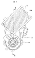
- FIG. 1 is a schematic view of a power steering apparatus according to a first embodiment of the present invention. It is the figure which looked at the power steering apparatus shown in FIG. 1 from the arrow A direction.
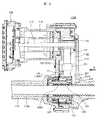
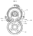
- FIG. 3 is a cross-sectional view of the power steering device taken along the line III-III in FIG. It is a perspective view of the assist mechanism part of a power steering device. It is the figure which looked at the assist mechanism shown in FIG. 3 from the arrow B direction. It is a figure which shows the relationship of a pulley tensioner and an endless belt in the state (neutral state) to which a driving force is not provided by the electric motor which concerns on 1st Example of this invention.
- FIG. 1 is a schematic view of a power steering apparatus according to a first embodiment of the present invention.
- FIG. 2 is a view of the power steering apparatus shown in FIG. 1 as viewed in the direction of arrow A.
- FIG. 3 is a cross-sectional view of the power steering apparatus taken along line III-III of FIG.
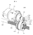
- FIG. 4 is a perspective view of an assist mechanism of the power steering apparatus.
- a steering wheel 101 disposed in a driver's cab of a vehicle and a steered wheel 102A, 102B, which is a front wheel of the vehicle, are mechanically connected by a steering mechanism 103A. It is done.
- the steering mechanism 103A is an iron-based metallic material (steel material (steel material) connected to the steering shaft 106 via the intermediate shaft 104 and the universal joint 105 so as to rotate integrally with the steering shaft 106 via a torsion bar (not shown). And a pinion shaft 107).
- the steering mechanism 103A also includes a pinion 107A provided on the outer periphery of the pinion shaft 107, and a steered shaft 108 made of an iron-based metal material (steel material).
- the outer periphery of the steering shaft 108 is provided with a rack 108A that meshes with the pinion 107A.
- the steered shaft 108 includes a steered shaft main body 108B and a steered shaft side ball screw groove 108C.
- the turning shaft side ball screw groove 108C is a spiral groove formed in a spiral shape on the outer periphery of the turning shaft main body portion 108B.
- both ends of the steered shaft 108 are connected to the corresponding steered wheels 102A and 102B via the ball joints 109 and 110, the tie rods 111 and 112, the knuckle arms 113 and 114, etc.
- the driver rotates the steering wheel 101
- the intermediate shaft 104 and the steering shaft 106 are rotated about the axis
- the torsion bar is twisted, and the elastic force of the torsion bar causes the pinion shaft 107 to be steered. It rotates following the axis 106.
- the rotational movement of the pinion shaft 107 is converted to linear movement along the axial direction of the steered shaft 108 by the rack and pinion mechanism including the rack 108A and the pinion 107A, and knuckles through the ball joints 109 and 110 and the tie rods 111 and 112.
- the rack and pinion mechanism including the rack 108A and the pinion 107A, and knuckles through the ball joints 109 and 110 and the tie rods 111 and 112.
- the direction of the steered wheels 102A and 102B is changed.
- the steered wheels 102A and 102B are steered as the steered shaft body 108B moves in the longitudinal direction.
- the steering mechanism 103A and an assist mechanism 103B described later are accommodated inside a housing 115 having a turning shaft accommodation space 115A and a reduction gear accommodation space 115B.
- the steered shaft accommodation space 115A accommodates at least a part of the steered shaft 108, and accommodates the steered shaft 108 so as to be movable in the axial direction.
- the reduction gear housing space 115B is disposed midway (intermediate portion) in the axial direction of the steered shaft housing space 115A in the longitudinal direction of the steered shaft main body portion 108B, and houses a reduction gear described later.
- bellows-like boots 116 and 117 covering the outer periphery of one end side of the tie rods 111 and 112 are provided at both axial ends of the housing 115, respectively.
- the bellows-like boots 116 and 117 are formed of, for example, a synthetic rubber material or the like so as to secure a predetermined flexibility, and prevent entry of water, dust, etc. into the steering shaft 108 or a ball screw mechanism 123 described later. ing.
- the electric motor 118 for applying a steering force to the steering mechanism 103 A includes a motor pulley 120 (first pulley) provided on the outer periphery of the tip end portion of the output shaft 119 and the steered shaft 108.
- a nut pulley 121 (second pulley) provided on the outer periphery is linked with the steering shaft 108 by being connected via the endless belt 122.
- the motor pulley 120, the nut pulley 121 and the endless belt 122 constitute a transmission mechanism.
- a plurality of motor pulley teeth 120A are formed on the outer periphery of the motor pulley 120.
- a plurality of nut pulley teeth 121A are formed on the outer periphery of the nut pulley 121.
- a plurality of belt teeth 122A are formed on the endless belt 122, and are engaged with the plurality of motor pulley teeth 120A and the plurality of nut pulley teeth 121A.
- the plurality of motor pulley teeth 120A, the plurality of nut pulley teeth 121A, and the plurality of belt teeth 122A are formed to be inclined with respect to the rotation axis of the output shaft 119.
- the diameter of the motor pulley 120 is smaller than the diameter of the nut pulley 121.
- the diameter of the nut pulley 121 is larger than the diameter of the motor pulley 120.
- the outer diameter of the large diameter nut pulley 121 is longer than that of the motor pulley 120. Therefore, the contact area between the nut pulley 121 and the endless belt 122 is also larger than that of the motor pulley 120. Conversely, the contact area of the motor pulley 120 with the endless belt 122 is smaller than that of the nut pulley 121.
- a ball screw mechanism 123 having a helical groove shape, which is a reduction gear, is provided.
- the ball screw mechanism 123 is provided on the outer peripheral surface of the steered shaft 108, and is provided in an annular shape so as to surround the steered shaft 108 and a steered shaft side ball screw groove 108C having a spiral groove shape.
- a nut 124 made of an iron-based metal material rotatably provided relative to the shaft 108 is provided.
- the nut 124 is provided with a cylindrical main body portion 124A formed in a cylindrical shape.
- a nut-side ball screw groove 125 formed in a spiral shape is formed on the inner peripheral side of the cylindrical main body portion 124A.
- the cylindrical main body portion 124 ⁇ / b> A is rotatably provided in the reduction gear housing space 115 ⁇ / b> B, and has a cylindrical shape surrounding the steering shaft 108.
- a ball circulation groove 126 is formed by the steered shaft side ball screw groove 108 C and the nut side ball screw groove 125.
- a plurality of metal balls 127 are filled in the ball circulation groove 126. That is, the plurality of balls are provided between the turning shaft side ball screw groove 108 C and the nut side ball screw groove 125.
- a tube (circulation mechanism) not shown is attached to the nut 124.
- the tube is formed of a synthetic resin.
- the tube circulates the plurality of balls 127 from one end side to the other end side of the ball circulation groove 126, and includes a circulation path in which the balls 127 can move.
- the rotation axis of the output shaft 119 of the electric motor 118 is provided at a position offset from the rotation axis of the nut 124.
- the rotation of the electric motor 118 transmitted through the endless belt 122 is converted into the linear motion of the steered shaft 108 while being decelerated by the ball screw mechanism 123.
- a control unit (ECU) 128 as a control unit is integrally formed with the electric motor 118 and has a function of storing and executing various control processes, and based on information such as steering angle, steering torque and vehicle speed, It drives and controls an electric motor 118 that applies a steering assist torque to the steering mechanism 103A.
- the driver's sudden operation of the steering wheel or a strong impact from the road surface increases the tension of the belt.
- so-called tooth skipping occurs in which the meshing of the teeth formed on the motor pulley 120, the nut pulley 121 and the endless belt 122 is shifted.
- the pulley tensioner 200 is provided in the present embodiment.
- FIG. 5 is a view of the assist mechanism shown in FIG.
- the pulley tensioner 200 includes a tensioner base 201, a first tensioner portion 202, and a second tensioner portion 203.
- the tensioner base 201 is formed substantially in a T-shape as viewed from the axial direction side of the rotation shaft of the output shaft 119, as particularly shown in FIG.
- the tensioner base 201 is opposite to the first connecting portion 201A extending from the tensioner base 201 in the rotational axis direction of the output shaft 119, the second connecting portion 201B, the first connecting portion 201B, and the second connecting portion 201B. And a rocking base 201C extending to the
- the first tensioner portion 202 is connected to the tensioner base 201 by a first connection portion 201A. Further, the second tensioner portion 203 is connected to the tensioner base 201 by a second connection portion 201B.
- the housing 115 is formed with a bearing portion 204 that rotatably supports the swing base 201C.
- the bearing portion 204 is provided on the nut pulley 121 side, and the swing base 201C is also located on the nut pulley 121 side.
- the tensioner base 201 extends from the side of the nut pulley 121 where the swing base 201C is located toward the side of the motor pulley 120.
- the tensioner base 201 along with the first connection portion 201A, the second connection portion 201B, and the rocking base 201C, is provided so as to be rockable with the rocking base 201C as a rocking center in the reduction gear housing space 115B. .
- the swing base portion 201 C has a nut pulley 121 more than the second reference axis 304 when the axis connecting the first tensioner portion 202 and the second tensioner portion 203 is the second reference axis 304 in the orthogonal cross section of the rotation axis of the motor pulley 120. It is equipped on the side (second pulley side). In addition, the swing base 201C is provided on the line of the first reference axis 301.
- the swing base 201C is held so as not to move in the reduction gear housing space 115B. In other words, the swing base 201C is held on the first reference axis 301 without moving in the direction of the second reference axis 304.
- the distance between the first tensioner portion 202 and the second tensioner portion 203 is kept constant.
- the pulley tensioner 200 is provided such that the second reference axis is positioned closer to the motor pulley 120 than the midpoint between the rotation center of the motor pulley 120 and the rotation center of the nut pulley 121.
- An endless belt 122 is located at the opposing portion of the first tensioner portion 202 and the second tensioner portion 203.
- the outer peripheral side of the endless belt 122 is in contact with the first tensioner portion 202 and the second tensioner portion 203.
- tension is applied to the endless belt 122 stretched by the motor pulley 120 and the nut pulley 121.
- the tension applied to the endless belt 122 changes the distance between the contact portion where the endless belt 122 and the first tensioner portion 202 contact and the contact portion where the endless belt 122 and the second tensioner portion 203 contact. It can be adjusted by In the present embodiment, the minimum value of the distance between the contact portions is smaller than the outer diameter of the motor pulley 120.
- FIG. 6A is a view showing a relationship between a pulley tensioner and an endless belt in a state (neutral state) in which a driving force is not applied by the electric motor according to the first embodiment of the present invention.
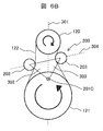
- FIG. 6B is a view showing a relationship between a pulley tensioner and an endless belt in a state where a driving force is applied in a clockwise direction (clockwise direction) by the electric motor according to the first embodiment of the present invention.
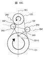
- FIG. 6C is a view showing a relationship between a pulley tensioner and an endless belt in a state where a driving force is applied in the counterclockwise direction (counterclockwise direction) by the electric motor according to the first embodiment of the present invention.
- the side with the smaller radius is the motor pulley 120 (first pulley), and the side with the larger radius is the nut pulley 121 (second pulley).
- first reference axis 301 In a cross section orthogonal to the rotation axis of the motor pulley 120, an axis connecting the rotation axis of the motor pulley 120 and the rotation axis of the nut pulley 121 is taken as a first reference axis 301.
- one side (left side) of the first reference axis 301 is set as a first area 302, and the other side (right side) is set as a second area 303.
- the first tensioner portion 202 is provided on the opposite side of the first reference axis 301 to the first region 302 of the endless belt 122, and is connected to the tensioner base 201 at the first connection portion 201A.
- the second tensioner portion 203 is provided on the opposite side of the first reference axis 301 to the second region 303 of the endless belt 122, and is connected to the tensioner base 201 at the second connection portion 201B.
- the pulley tensioner 200 has a distance between the contact portion 305 between the first tensioner portion 202 and the first region 302 of the endless belt 122 and the contact portion 306 between the second tensioner portion 203 and the second region 303 of the endless belt 122. Is set to be smaller than the outer diameter of the motor pulley 120 (first pulley).
- the first reference axis 301 is set to be closer to a tangent line formed by the outer diameter of the motor pulley 120 (first pulley) and the outer diameter of the nut pulley 121 (second pulley).
- the second tensioner portion 203 approaches the motor pulley 120 by moving upward in the direction of gravity. Furthermore, the second tensioner portion 203 approaches the first reference axis 301. With the operation of the second tensioner portion 203, the winding angle of the endless belt 122 around the motor pulley 120 increases, and the meshing area between the motor pulley 120 and the endless belt 122 increases.
- the first tensioner portion 202 approaches the motor pulley 120 by moving upward in the direction of gravity. Furthermore, the first tensioner portion 202 approaches the first reference axis 301. With the operation of the first tensioner portion 202, the winding angle of the endless belt 122 around the motor pulley 120 increases, and the meshing area between the motor pulley 120 and the endless belt 122 increases.
- the meshing area with the belt also becomes smaller. For this reason, if the belt generates a sudden tension, it is likely to cause tooth skipping. In order to suppress this, it is preferable to increase the meshing area of the pulley and the belt.
- FIGS. 7A to 7C A reference example to the present embodiment will be described using FIGS. 7A to 7C.
- the same reference numerals are given to the same components as those in the present embodiment.
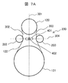
- FIG. 7A is a view showing a relationship between a pulley tensioner and an endless belt in a state (neutral state) in which a driving force is not applied by the electric motor according to a reference example.
- FIG. 7B is a view showing a relationship between a pulley tensioner and an endless belt in a state where a driving force is applied in a clockwise direction (clockwise direction) by an electric motor according to a reference example.
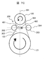
- FIG. 7C is a view showing a relationship between a pulley tensioner and an endless belt in a state where a driving force is applied in a counterclockwise direction (counterclockwise direction) by the electric motor according to the reference example.
- a notch groove 401 is formed along the axial direction of the second reference axis 304, and a central axis 402 is inserted in the notch groove 401.
- the central shaft 402 is located at the center of a line connecting the center of the first tensioner portion 202 and the center of the second tensioner portion 203.
- the central axis 402 is movable in the notch groove 401 in the left-right direction in FIG. 7A. However, rotation about the central axis 402 is blocked.
- the first tensioner portion 202 and the second tensioner portion 203 only move in the left-right direction as the motor pulley 120 rotates. Therefore, as compared with the present embodiment, the winding angle of the endless belt 122 around the motor pulley 120 can not be increased, and the meshing area between the motor pulley 120 and the endless belt 122 can not be increased.
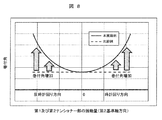
- FIG. 8 is a diagram comparing winding angles of the present embodiment and the reference example.
- the solid line is the present embodiment, and the dotted line is the reference example.
- the horizontal axis in FIG. 8 indicates the strength of tension on the endless belt 122 when it is rotated clockwise or counterclockwise starting from 0 at the center of the horizontal axis.
- the vertical axis indicates the winding angle of the endless belt 122 with respect to the motor pulley 120.
- the second tensioner portion 203 approaches the first reference axis 301, but the first tensioner portion 202 becomes the first reference by the movement of the second tensioner portion 203. As it moves away from the axis 301, the wrap angle does not change.
- the looseness of the endless belt 122 can be suppressed, and the meshing between the endless belt 122 and the motor pulley 120 (first pulley) and the nut pulley 121 (second pulley) can be improved.
- the swing center of the pulley tensioner 200 is close to the nut pulley 121 (second pulley) side which is the large diameter side pulley, and the second tensioner portion 203 moves in the direction approaching the motor pulley 120 (first pulley) side. Therefore, meshing of the motor pulley 120 (first pulley) on the small diameter pulley side can be improved. Since the small diameter pulley has a smaller number of meshing with the endless belt than the large diameter pulley, the transmission performance of the drive torque of the electric motor 118 can be improved by improving the meshing ratio on the small diameter pulley side.
- the motor pulley 120 is a small diameter pulley. As a result, a smaller torque and a smaller electric motor can be used, and the device can be miniaturized.
- the pulley tensioner 200 is provided such that the second reference axis 304 is located closer to the motor pulley 120 than the midpoint between the rotation center of the motor pulley 120 and the rotation center of the nut pulley 121.
- the swing radius which is the distance between the swing base 201C, the first tensioner portion 202, and the second tensioner portion 203, is relatively small, and hence the direction of the first reference axis 301 of the tensioner on the side closer to the motor pulley 120.
- the moving amount of the motor pulley 120 can be increased, and the meshing ratio of the motor pulley 120 can be further improved.
- the distance between the first tensioner portion 202 and the second tensioner portion 203 is kept constant. Therefore, according to the present embodiment, for example, when the first region 302 side of the endless belt 122 is pulled and the second region 303 side is loosened, the second tensioner portion 203 is the same as the movement amount of the first tensioner portion 202, Since it can move, the meshing ratio of the motor pulley 120 can be reliably improved.
- the swing base 201C is provided on the line of the first reference axis 301.
- the endless belt 122 can be tensioned in a well-balanced manner with respect to the rotation of the electric motor 118 in both directions, in other words, the movement of the steered wheels 102A and 102B in both directions.
- the swing base 201C is held so as not to move in the reduction gear housing space 115B.
- the second tensioner portion 203 can move by the same amount as the movement amount of the first tensioner portion 202, The meshing ratio of the first pulley can be reliably improved.
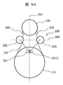
- FIG. 9A is a view showing a relationship between a pulley tensioner and an endless belt in a state (neutral state) where a driving force is not applied by the electric motor according to a second embodiment of the present invention.
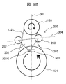
- FIG. 9B is a view showing a relationship between a pulley tensioner and an endless belt in a state where a driving force is applied in a clockwise direction (clockwise direction) by the electric motor according to the second embodiment of the present invention.
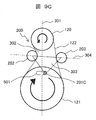
- FIG. 9C is a view showing a relationship between a pulley tensioner and an endless belt in a state where a driving force is applied in a counterclockwise direction (counterclockwise direction) by the electric motor according to the second embodiment of the present invention.
- the housing 115 (see FIG. 3) is formed with a notch 501 extending in the direction of the second reference axis 304.
- the swing base 201C is inserted into the notch 501, and the swing base 201C is movable along the notch 501.
- the swing base 201C is provided so as to be movable along the direction of the second reference axis 304.
- the swing base 201C is provided so as to be movable toward the first area 302 and the second area 303 across the first reference axis 301.
- the second tensioner portion 203 approaches the motor pulley 120 by moving upward in the direction of gravity. Furthermore, the second tensioner portion 203 approaches the first reference axis 301. With the operation of the second tensioner portion 203, the winding angle of the endless belt 122 around the motor pulley 120 increases, and the meshing area between the motor pulley 120 and the endless belt 122 increases.
- the first tensioner portion 202 approaches the motor pulley 120 by moving upward in the direction of gravity. Furthermore, the first tensioner portion 202 approaches the first reference axis 301. With the operation of the first tensioner portion 202, the winding angle of the endless belt 122 around the motor pulley 120 increases, and the meshing area between the motor pulley 120 and the endless belt 122 increases.
- the second tensioner portion 203 moves by the same amount as the movement amount of the first tensioner portion 202.
- the meshing ratio of the motor pulley 120 (first pulley) can be reliably improved.
- the swing base 201C is provided movable along the direction of the second reference axis 304, the amount of movement of the pulley tensioner 200 in the second reference axial direction is increased, and the motor pulley 120 (first The meshing ratio of the pulley can be improved.
- the rocking base 201C is provided so as to be movable toward the first area 302 and the second area 303 across the first reference axis 301, so both sides of the steering wheels 102A and 102B are provided.
- the endless belt 122 can be tensioned in a balanced manner with respect to the movement of steering in the direction.
- FIGS. 10A to 10C a third embodiment according to the present invention will be described with reference to FIGS. 10A to 10C.
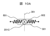
- the third embodiment is characterized in the second embodiment (FIGS. 9A to 9C) in the return mechanism for returning the rocking base 201C in the direction approaching the first reference axis 301.
- FIG. 10A is a view showing the state of the rocking base returning mechanism in the neutral state according to the third embodiment of the present invention.
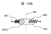
- FIG. 10B is a view showing a state of the swing base return mechanism in a state where the driving force is applied in the clockwise direction (clockwise direction) by the electric motor according to the third embodiment of the present invention.
- FIG. 10C is a view showing the state of the rocking base return mechanism in a state where the driving force is applied in the counterclockwise direction (counterclockwise direction) by the electric motor according to the third embodiment of the present invention.
- the swing base 201C is provided with swing return mechanisms 601 and 602 to the left and right with the first reference axis 301 as a boundary.
- coil springs are used as the swing return mechanisms 601 and 602.
- One end side of the swing return mechanisms 601 and 602 is in contact with the swing base 201 C, and the other end is fixed to the housing 115.
- the swing base 201C When the electric motor 118 is not operating, the swing base 201C is located on the first reference axis 301. In this state, the swing base 201C is biased by the swing return mechanisms 601 and 602 and held on the first reference axis 301.
- the swing base 201C is returned onto the first reference axis 301 by the biasing force of the swing return mechanism 601 (see FIG. 10A).
- the swing base 201C is returned onto the first reference axis 301 by the biasing force of the swing return mechanism 602 (see FIG. 10A).
- the tension of both sides of the endless belt 122 is kept close by the rocking return mechanisms 601 and 602, whereby the rotation of the electric motor 118 is resumed.
- the steering response of the vehicle can be improved.
- the pulley tensioner 200 is returned toward the first reference axis 301 in the middle point between the first tensioner portion 202 and the second tensioner portion 203. It is characterized by the return mechanism.
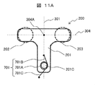
- FIG. 11A is a view showing the state of the tensioner return mechanism in the neutral state according to the fourth embodiment of the present invention.
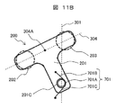
- FIG. 11B is a view showing a state of the tensioner return mechanism in a state where the driving force is applied in the clockwise direction (clockwise direction) by the electric motor according to the fourth embodiment of the present invention.
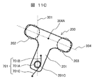
- FIG. 11C is a view showing a state of the tensioner return mechanism in a state where the driving force is applied in the counterclockwise direction (counterclockwise direction) by the electric motor according to the fourth embodiment of the present invention.
- the pulley tensioner 200 is provided with a torsion spring 701 as a tensioner return mechanism.
- the inner peripheral portion of the winding portion 701A of the torsion spring 701 is inserted into the rocking base 201C.
- One arm portion 701 B of the torsion spring 701 is fixed to the tensioner base 201.
- the other arm 701 C of the torsion spring 701 is fixed to the housing 115.
- the midpoint 304 A of the first tensioner portion 202 and the second tensioner portion 203 in the direction of the second reference axis 304 is at a position close to the first reference axis 301.
- the rotation of the electric motor 118 when the rotation of the electric motor 118 is stopped, the rotation of the electric motor 118 is resumed by keeping the tension on both sides of the endless belt 122 equal by the torsion spring 701 as a tensioner return mechanism.
- the steering response at the time can be improved.
- the present invention is not limited to the embodiments described above, and includes various modifications.
- the above-described embodiments are described in detail to explain the present invention in an easy-to-understand manner, and are not necessarily limited to those having all the configurations described.
- the present invention includes not only a front wheel steering system but also a rear wheel steering system.
- the power steering device is a steered shaft, and includes a steered shaft main body portion and a steered shaft side ball screw groove;
- the steered shaft is a steering shaft according to movement in the longitudinal direction, and the steered shaft side ball screw groove is a helical groove formed in the steered shaft main body portion, and the housing is a steered shaft and a housing.
- a steering shaft housing space and a reduction gear housing space wherein the steering shaft housing space houses at least a part of the steering shaft, and the gear housing space is the steering wheel
- the housing which is a space provided in the middle of the steering shaft accommodation space in the longitudinal direction of the shaft main body, is a nut, and includes a cylindrical main body and a nut-side ball screw groove; Is rotatable within the reduction gear housing space And the nut side ball screw groove is a spiral groove provided on the inner peripheral side of the cylindrical main body, A plurality of balls provided between the steered shaft side ball screw groove and the nut side ball screw groove, and an electric motor having an output shaft;
- the electric motor and the motor pulley are provided at positions offset from the rotation axis of the nut, and the motor pulley has a plurality of motor pulley teeth, and the output of the electric motor is The motor pulley provided on the shaft, and a nut pulley having a plurality of nut pulley teeth, the nut pulley provided
- the first pulley is the motor pulley
- the second pulley is the nut pulley
- the pulley tensioner may be configured such that the second reference axis is closer to a center point between the rotation center of the first pulley and the rotation center of the second pulley. It is provided to be located on the side close to the first pulley.
- the tensioner base maintains a constant distance between the first tensioner portion and the second tensioner portion.
- the rocking base is provided on a line of the first reference axis.
- the rocking base is fixed so as not to move in the reduction gear housing space.
- the rocking base is provided movably along the direction of the second reference axis.
- the pulley tensioner includes a swing base return mechanism, and the swing base return mechanism is configured such that the swing base corresponds to the first reference axis.
- the swing base is biased in the approaching direction.
- the swing base is provided movably toward the first area side and the second area side across the first reference axis. It is done.
- the power steering apparatus includes a tensioner return mechanism, and the tensioner return mechanism is configured to receive the first tensioner portion in the direction of the second reference axis.
- the pulley tensioner is biased in a direction in which a midpoint of the second tensioner portion approaches the first reference axis.
Landscapes
- Engineering & Computer Science (AREA)
- General Engineering & Computer Science (AREA)
- Mechanical Engineering (AREA)
- Chemical & Material Sciences (AREA)
- Combustion & Propulsion (AREA)
- Transportation (AREA)
- Power Steering Mechanism (AREA)
- Devices For Conveying Motion By Means Of Endless Flexible Members (AREA)
- Transmission Devices (AREA)
Abstract
半径の小さい第1プーリであるモータプーリ(120)と半径の大きい第2プーリであるナットプーリ(121)とを接続する無端ベルト(122)と、無端ベルト(122)に張力を与えるプーリテンショナー(200)と備え、プーリテンショナー(200)はテンショナー基部(201)と、第1テンショナー部(202)と、第2テンショナー部(203)とを備え、テンショナー基部(201)には揺動基部(201C)が備えられ、揺動基部(201C)をナットプーリ(121)側に配置し、第1テンショナー部(202)と無端ベルト(122)の接触部と第2テンショナー部(203)と無端ベルト(122)の接触部との間の距離の最小値を、モータプーリ(120)の外径よりも小さくした。
Description
本発明は、車両に用いるパワーステアリング装置に関する。
従来のパワーステアリング装置としては、例えば特許文献1に記載の技術が提案されている。
特許文献1には、モータの駆動力を、ベルトを介してラックバー(転舵軸)に伝達する技術が開示されている。モータとラックバーには、それぞれベルトを巻き掛けるプーリを備えている。
ナットプーリとモータプーリをベルトで連結する方式では、運転者がハンドルを急激に操作したり、路面から強い衝撃を受けると、ベルトの張力が大きくなる。すると、ナットプーリ、モータプーリ及びベルトに形成された歯の噛み合いがずれる、いわゆる歯飛びが発生する。これを防止するために、特許文献1ではベルトの張力を調整する張力調整部材を備えている。
特許文献1に記載の張力調整部材は、ナットプーリに対して径の小さいモータプーリ側に取り付けられている。張力調整部材は、ベルトに係る張力に合わせて左右方向に移動することで、モータプーリとベルトとの噛み合いを増加させている。
しかしながら、特許文献1に記載の技術では、張力調整部材が径の小さいモータプーリ側に近づくものではなく、モータプーリとベルトとの噛み合いをより増加させることが困難であった。このため、小径プーリ側とベルトとの歯飛びを抑制することが困難であった。
そこで本発明の目的は、前記課題を解決し、プーリとベルトとの噛み合いを向上させ、歯飛びを抑制するパワーステアリング装置を提供することにある。
本発明によれば、その1つの態様において、半径の小さい第1プーリと半径の大きい第2プーリとを接続する無端ベルトと、前記無端ベルトに張力を与えるプーリテンショナーと備え、前記プーリテンショナーはテンショナー基部と、第1テンショナー部と、第2テンショナー部とを備え、前記テンショナー基部には揺動基部が備えられ、前記揺動基部を前記第2プーリ側に配置し、前記第1テンショナー部と前記無端ベルトの接触部と前記第2テンショナー部と前記無端ベルトの接触部との間の距離の最小値が前記第1プーリの外径よりも小さくした。
本発明によれば、プーリとベルトとの噛み合いを向上させ、歯飛びを抑制することができる。
以下、本発明に係るパワーステアリング装置の実施例を、図面に基づいて説明する。本発明は、以下の実施例に限定されることなく、本発明の技術的な概念の中で種々の変形例や応用例も、その範囲に含むものである。
図1は、本発明の第1実施例に係るパワーステアリング装置の概略図である。図2は、図1に示すパワーステアリング装置を矢印A方向から見た図である。図3は、図2のIII-III線に沿ったパワーステアリング装置の断面図である。図4は、パワーステアリング装置のアシスト機構部の斜視図である。
図1~図4に示すように、パワーステアリング装置100は、車両の運転室内に配置されたステアリングホイール101と、車両の前輪である操舵輪102A,102Bとが、操舵機構103Aによって機械的に連結されている。操舵機構103Aは、中間軸104および自在継手105を介して一体的に回転するように連結された操舵軸106と、操舵軸106に図示しないトーションバーを介して連結された鉄系金属材料(鋼材)からなるピニオン軸107とを備えている。
また、操舵機構103Aは、ピニオン軸107の外周に備えられたピニオン107Aと、鉄系金属材料(鋼材)からなる転舵軸108とを備えている。転舵軸108の外周には、ピニオン107Aと噛み合うラック108Aを備えている。
転舵軸108は、転舵軸本体部108Bと、転舵軸側ボールねじ溝108Cを備えている。転舵軸側ボールねじ溝108Cは、転舵軸本体部108Bの外周に螺旋状に形成された螺旋溝である。
そして、転舵軸108の両端部は、それぞれボールジョイント109,110、タイロッド111,112およびナックルアーム113,114等を介して対応する操舵輪102A,102Bに連結されている このような構成により、運転者がステアリングホイール101を回転操作すると、これに伴って中間軸104および操舵軸106が軸回りに回転してトーションバーが捩られ、これにより生じるトーションバーの弾性力によって、ピニオン軸107が操舵軸106に追従して回転する。
そして、ピニオン軸107の回転運動がラック108Aおよびピニオン107Aからなるラック&ピニオン機構により転舵軸108の軸方向に沿う直線運動に変換され、ボールジョイント109,110およびタイロッド111,112を介してナックルアーム113,114が車幅方向へと引っ張られることによって、操舵輪102A,102Bの向きが変更される。換言すれば、転舵軸本体部108Bが長手方向に移動するに伴い、操舵輪102A,102Bが転舵される。
操舵機構103Aおよび後述するアシスト機構103Bは、転舵軸収容空間115A及び減速機収容空間115Bを有するハウジング115の内部に収容されている。転舵軸収容空間115Aは、転舵軸108の少なくとも一部を収容するものであって、転舵軸108を軸方向移動可能に収容する。減速機収容空間115Bは、転舵軸本体部108Bの長手方向において転舵軸収容空間115Aの軸方向の途中(中間部)に配置され、後述する減速機を収容する。
さらに、ハウジング115の軸方向両端には、それぞれタイロッド111,112の一端側外周を覆う蛇腹状のブーツ116,117が設置されている。蛇腹状のブーツ116,117は、例えば合成ゴム材料等により所定の可撓性を確保するように形成され、転舵軸108や後述するボールねじ機構123への水や埃等の侵入を防止している。
操舵機構103Aに操舵力を付与する電動モータ118は、図3及び図4に示すように、その出力軸119の先端部外周に備えられたモータプーリ120(第1プーリ)と、転舵軸108の外周に備えられたナットプーリ121(第2プーリ)とが無端ベルト122を介して接続されることで、転舵軸108と連係されている。モータプーリ120,ナットプーリ121および無端ベルト122をもって、伝達機構が構成されている。モータプーリ120の外周には、複数のモータプーリ歯部120Aが形成されている。同様にナットプーリ121の外周には、複数のナットプーリ歯部121Aが形成されている。また、無端ベルト122には複数のベルト歯部122Aが形成されており、複数のモータプーリ歯部120Aと複数のナットプーリ歯部121Aと噛み合っている。複数のモータプーリ歯部120A、複数のナットプーリ歯部121A及び複数のベルト歯部122Aは、出力軸119の回転軸線に対し、傾斜して形成されている。モータプーリ120の直径は、ナットプーリ121の直径に比べ、小径となっている。逆にナットプーリ121の直径は、モータプーリ120の直径に比べ、大径となっている。モータプーリ120、ナットプーリ121と無端ベルト122との接触関係を見てみると、径の大きいナットプーリ121は、モータプーリ120に比較し、その外周も長くなる。このため、ナットプーリ121は、無端ベルト122との接触面積もモータプーリ120に比較し、大きくなる。逆に、モータプーリ120は、無端ベルト122との接触面積はナットプーリ121に比較し、小さい。
ナットプーリ121と転舵軸108との間には、減速機である螺旋状の溝形状を有するボールねじ機構123を備えている。
ボールねじ機構123は、転舵軸108の外周面に備えられ、螺旋状の溝形状を有する転舵軸側ボールねじ溝108Cと、転舵軸108を包囲するように環状に備えられ、転舵軸108に対し回転可能に設けられた鉄系金属材料からなるナット124を備えている。
ナット124は、筒状に形成された筒状本体部124Aを備えている。筒状本体部124Aの内周側には、螺旋状に形成されたナット側ボールねじ溝125が形成されている。筒状本体部124Aは、減速機収容空間115B内で回転可能に設けられ、転舵軸108を包囲する筒形状を有している。
そして、転舵軸側ボールねじ溝108Cとナット側ボールねじ溝125とにより、ボール循環溝126が構成される。ボール循環溝126内には、金属製のボール127が複数個充填されている。すなわち、複数のボールは、転舵軸側ボールねじ溝108Cとナット側ボールねじ溝125の間に設けられている。
また、ナット124には、図示しないチューブ(循環機構)が取り付けられている。チューブは、合成樹脂で形成されている。チューブは、複数のボール127をボール循環溝126の一端側から他端側へ循環させるものであり、内部にボール127が移動可能な循環路を備えている。
電動モータ118の出力軸119の回転軸線は、ナット124の回転軸線とオフセットした位置に設けられている。無端ベルト122を介して伝達される電動モータ118の回転は、ボールねじ機構123によって減速されながら転舵軸108の直線運動に変換されるようになっている。
コントロールユニットとしての制御ユニット(ECU)128は、電動モータ118と一体に構成され、各種制御処理を記憶および実行する機能を有しており、操舵角、操舵トルクおよび車速等の情報に基づいて、操舵機構103Aに操舵アシストトルクを付与する電動モータ118を駆動制御する。
本実施例にように、モータプーリ120とナットプーリ121とをベルトを介して接続する構成においては、運転者がハンドルを急激に操作したり、路面から強い衝撃を受けるとベルトの張力が大きくなる。すると、モータプーリ120、ナットプーリ121及び無端ベルト122に形成された歯部の噛み合いがずれる、いわゆる歯飛びが発生する。これを防止するために、本実施例では、プーリテンショナー200を備えている。
次に、プーリテンショナー200の構成について、図3~図5を用いて説明する。図5は、図3に示すアシスト機構を矢印B方向から見た図である。
プーリテンショナー200は、テンショナー基部201と、第1テンショナー部202と、第2テンショナー部203とを備えている。テンショナー基部201は、特に図5に示すように、出力軸119の回転軸の軸方向側から見て略T字状に形成されている。
テンショナー基部201は、テンショナー基部201から出力軸119の回転軸線方向に延びた第1接続部201Aと、第2接続部201Bと、この第1接続部201Bと、第2接続部201Bとは反対方向に延びた揺動基部201Cとを備えている。
第1テンショナー部202は、第1接続部201Aによってテンショナー基部201に接続されている。また、第2テンショナー部203は、第2接続部201Bによってテンショナー基部201に接続されている。
ハウジング115には、揺動基部201Cを回転可能に支持する軸受部204が形成されている。この軸受部204は、ナットプーリ121側に設けられており、揺動基部201Cもナットプーリ121側に位置している。そして、テンショナー基部201は、揺動基部201Cが位置するナットプーリ121側からモータプーリ120側に向かって延びている。
テンショナー基部201は、第1接続部201Aと、第2接続部201Bと、揺動基部201Cと共に、減速機収容空間115B内において、揺動基部201Cを揺動中心として揺動可能に設けられている。
揺動基部201Cは、モータプーリ120の回転軸線の直交断面において、第1テンショナー部202と第2テンショナー部203とを結ぶ軸線を第2基準軸線304としたとき、第2基準軸線304よりもナットプーリ121側(第2プーリ側)に備えている。また、揺動基部201Cは第1基準軸線301の線上に設けられている。
揺動基部201Cは、減速機収容空間115B内において、移動しないように保持されている。換言すれば、揺動基部201Cは、第2基準軸線304方向に移動することなく、第1基準軸線301上で保持されている。
第1テンショナー部202と第2テンショナー部203との間の距離は、一定に保持されている。
プーリテンショナー200は、第2基準軸線がモータプーリ120の回転中心とナットプーリ121の回転中心の中点よりもモータプーリ120に近い側に位置するように備えている。
第1テンショナー部202と第2テンショナー部203の対向する部分には、無端ベルト122が位置している。無端ベルト122の外周側は、第1テンショナー部202と第2テンショナー部203に接触している。第1テンショナー部202と第2テンショナー部203が無端ベルト122に接触することにより、モータプーリ120とナットプーリ121に張られた無端ベルト122に張力が付与される。無端ベルト122に付与される張力は、無端ベルト122と第1テンショナー部202とが接触する接触部と、無端ベルト122と第2テンショナー部203とが接触する接触部との間の距離を変えることによって調整することができる。本実施例では、これら接触部間の距離の最小値が、モータプーリ120の外径より小さくなっている。
次に、図6を用いて、本実施例の動作について説明する。図6Aは、本発明の第1実施例に係る電動モータによって駆動力が付与されていない状態(中立状態)におけるプーリテンショナーと無端ベルトとの関係を示す図である。図6Bは、本発明の第1実施例に係る電動モータによって時計回りの方向(右回り方向)に駆動力が付与された状態におけるプーリテンショナーと無端ベルトとの関係を示す図である。図6Cは、本発明の第1実施例に係る電動モータによって反時計回りの方向(左回り方向)に駆動力が付与された状態におけるプーリテンショナーと無端ベルトとの関係を示す図である。
図6A~図6Cにおいて、半径が小さい側がモータプーリ120(第1プーリ)、半径の大きい側がナットプーリ121(第2プーリ)となっている。
モータプーリ120の回転軸線の直交断面において、モータプーリ120の回転軸線とナットプーリ121の回転軸線を結ぶ軸線を第1基準軸線301とする。無端ベルト122のうち第1基準軸線301の一方側(左側)を第1領域302、他方側(右側)を第2領域303とする。
第1テンショナー部202は、無端ベルト122の第1領域302に対して第1基準軸線301の反対側に設けられており、第1接続部201Aにおいてテンショナー基部201に接続されている。
第2テンショナー部203は、無端ベルト122の第2領域303に対して第1基準軸線301の反対側に設けられており、第2接続部201Bにおいてテンショナー基部201に接続されている。
プーリテンショナー200は、第1テンショナー部202と無端ベルト122の第1領域302との接触部305と、第2テンショナー部203と無端ベルト122の第2領域303との接触部306との間の距離の最小値が、モータプーリ120(第1プーリ)の外径よりも小さくなるように設定されている。
換言すれば、プーリテンショナー200は、第1テンショナー部202と無端ベルト122の第1領域302との接触部305と、第2テンショナー部203と無端ベルト122の第2領域303との接触部306が、モータプーリ120(第1プーリ)の外径とナットプーリ121(第2プーリ)の外径からなる接線よりも第1基準軸線301側になるように設定されている。
図6Bにおいて、電動モータ118によりモータプーリ120が時計回りの方向(右回り方向)に回転すると、無端ベルト122の左側(第1領域302側)が伸長し、右側(第2領域303側)が緩められる。この時、プーリテンショナー200は、揺動基部201Cを中心として回転し、第1テンショナー部202が重力方向の下方に移動し、第2テンショナー部203が重力方向の上方に移動する(第2基準軸線304は、右側が上に位置するように傾斜する)。
そして、第2テンショナー部203は、重力方向の上方に移動することによりモータプーリ120に近づく。さらに、第2テンショナー部203は、第1基準軸線301に近づく。第2テンショナー部203の動作に伴い、モータプーリ120への無端ベルト122の巻付角が増加し、モータプーリ120と無端ベルト122との噛み合い面積が増加する。
次に、モータプーリ120が反時計回りの方向(左回り方向)に回転した時の状態について、図6Cを用いて説明する。
図6Cにおいて、電動モータ118によりモータプーリ120が反時計回りの方向(左回り方向)に回転すると、無端ベルト122の右側(第2領域303側)が伸長し、左側(第1領域302側)が緩められる。この時、プーリテンショナー200は、揺動基部201Cを中心として回転し、第1テンショナー部202が重力方向の上方に移動し、第2テンショナー部203が重力方向の下方に移動する(第2基準軸線304は、左側が上に位置するように傾斜する)。
そして、第1テンショナー部202は、重力方向の上方に移動することによりモータプーリ120に近づく。さらに、第1テンショナー部202は、第1基準軸線301に近づく。第1テンショナー部202の動作に伴い、モータプーリ120への無端ベルト122の巻付角が増加し、モータプーリ120と無端ベルト122との噛み合い面積が増加する。
直径の小さいプーリは外周も短くなるので、ベルトとの噛み合い面積も小さくなる。このため、ベルトに急激な張力が発生すると、歯飛びが起きやすい。これを抑制するには、プーリとベルトの噛み合い面積を増加させるのが好ましい。
本実施例に対する参考例について、図7A~図7Cを用いて説明する。便宜上、本実施例と共通する構成については、同じ符号を付与する。
図7Aは、参考例に係る電動モータによって駆動力が付与されていない状態(中立状態)におけるプーリテンショナーと無端ベルトとの関係を示す図である。図7Bは、参考例に係る電動モータによって時計回りの方向(右回り方向)に駆動力が付与された状態におけるプーリテンショナーと無端ベルトとの関係を示す図である。図7Cは、参考例に係る電動モータによって反時計回りの方向(左回り方向)に駆動力が付与された状態におけるプーリテンショナーと無端ベルトとの関係を示す図である。
図7Aにおいて、参考例では、第2基準軸線304の軸線方向に沿って切欠き溝401が形成されており、この切欠き溝401には、中心軸402が挿入されている。中心軸402は、第1テンショナー部202の中心と、第2テンショナー部203の中心を結ぶ線の中心に位置している。中心軸402は、切欠き溝401内を図7Aにおける左右方向に移動可能となっている。ただし、中心軸402を中心とした回転は阻止されている。
図7Bにおいて、電動モータ118によりモータプーリ120が時計回りの方向(右回り方向)に回転すると、無端ベルト122の左側(第1領域302側)が伸長し、右側(第2領域303側)が緩められる。この時、プーリテンショナー200は、中心軸402が切欠き溝401に沿って左側へ移動し、第1テンショナー部202及び第2テンショナー部203も左側へ移動する。
次に、図7Cにおいて、電動モータ118によりモータプーリ120が反時計回りの方向(右回り方向)に回転すると、無端ベルト122の右側(第2領域303側)が伸長し、左側(第1領域302側)が緩められる。この時、プーリテンショナー200は、中心軸402が切欠き溝401に沿って右側(第2領域303側)へ移動し、第1テンショナー部202及び第2テンショナー部203も右側へ移動する。
本実施例に対し、参考例では、第1テンショナー部202及び第2テンショナー部203は、モータプーリ120の回転に伴い、左右方向に移動するだけである。このため、本実施例と比較して、モータプーリ120への無端ベルト122の巻付角を増加することができず、モータプーリ120と無端ベルト122との噛み合い面積を増加することができない。
本実施例の効果について、図8を用いて説明する。図8は、本実施例と参考例の巻付角を比較した図である。
図8において、実線は本実施例、点線は参考例である。図8における横軸は、横軸中央の0を起点として、時計回り方向、反時計回り方向に回転した時の無端ベルト122に対する張力の強さを示している。また、縦軸は、モータプーリ120に対する無端ベルト122の巻付角を示している。
図8において、本実施例では、例えばモータプーリ120が時計回りに回転し、無端ベルト122の張力が増加すると、第2テンショナー部203が第1基準軸線301及びモータプーリ120に近づき、巻付角が増加する。
一方、参考例では、例えばモータプーリ120が時計回りに回転すると、第2テンショナー部203は第1基準軸線301に近づくが、第2テンショナー部203が移動した分だけ第1テンショナー部202が第1基準軸線301から離れる方向に移動するので、巻付角が変化しない。
よって、本実施例によれば、無端ベルト122の緩みを抑制し、無端ベルト122とモータプーリ120(第1プーリ)、ナットプーリ121(第2プーリ)との噛み合いを向上させることができる。とりわけ、プーリテンショナー200の揺動中心が、大径側プーリであるナットプーリ121(第2プーリ)側に寄っており、第2テンショナー部203がモータプーリ120(第1プーリ)側に近づく方向に移動するため、小径プーリ側であるモータプーリ120(第1プーリ)の噛み合いを向上させることができる。小径プーリは、大径プーリに比べ、無端ベルトとの噛み合い数が少ないため、小径プーリ側の噛み合い率を向上させることで、電動モータ118の駆動トルクの伝達性能を向上させることができる。
また、本実施例ではモータプーリ120を小径プーリとしている。これにより、より小トルク、小型の電動モータを使用することができ、装置の小型化を図ることができる。
また、本実施例では、プーリテンショナー200は、第2基準軸線304がモータプーリ120の回転中心とナットプーリ121の回転中心の中点よりもモータプーリ120に近い側に位置するように備えている。これにより、揺動基部201Cと第1テンショナー部202、第2テンショナー部203との間の距離である揺動半径が比較的小さいため、モータプーリ120に近づく側のテンショナーの第1基準軸線301の方向の移動量を大きくすることができ、モータプーリ120の噛み合い率を更に向上させることができる。
また、本実施例では、第1テンショナー部202と第2テンショナー部203との間の距離は、一定に保持されている。このため、本実施例によれば、例えば無端ベルト122の第1領域302側が引っ張られ、第2領域303側が緩む場合、第2テンショナー部203は、第1テンショナー部202の移動量と同じ分、移動することができるため、確実にモータプーリ120の噛み合い率を向上させることができる。
また、本実施例では、揺動基部201Cは、第1基準軸線301の線上に備えている。これにより、電動モータ118の両側方向への回転、換言すれば、操舵輪102A、102Bの両側方向への転舵の動きに対し、バランスよく無端ベルト122に張力をかけることができる。
また、本実施例では、揺動基部201Cは、減速機収容空間115B内において、移動しないように保持されている。これにより、例えば無端ベルト122の第1領域302側が引っ張られ、第2領域303側が緩む場合、第2テンショナー部203は、第1テンショナー部202の移動量と同じ分、移動することができるため、確実に第1プーリの噛み合い率を向上させることができる。
次に、図9A~図9Cを用いて、本発明に係る第2実施例を説明する。図9Aは、本発明の第2実施例に係る電動モータによって駆動力が付与されていない状態(中立状態)におけるプーリテンショナーと無端ベルトとの関係を示す図である。図9Bは、本発明の第2実施例に係る電動モータによって時計回りの方向(右回り方向)に駆動力が付与された状態におけるプーリテンショナーと無端ベルトとの関係を示す図である。図9Cは、本発明の第2実施例に係る電動モータによって反時計回りの方向(左回り方向)に駆動力が付与された状態におけるプーリテンショナーと無端ベルトとの関係を示す図である。
図9Aにおいて、ハウジング115(図3参照)には、第2基準軸線304の方向に延びた切欠き部501が形成されている。切欠き部501には揺動基部201Cが挿入されており、揺動基部201Cは、この切欠き部501に沿って移動可能となっている。また、揺動基部201Cは、第2基準軸線304方向に沿って移動可能に設けられている。さらに揺動基部201Cは、第1基準軸線301を跨いで第1領域302側及び第2領域303側に向かって移動可能に設けられている。
図9Bにおいて、電動モータ118によりモータプーリ120が時計回りの方向(右回り方向)に回転すると、無端ベルト122の左側(第1領域302側)が伸長し、右側(第2領域303側)が緩められる。この時、プーリテンショナー200は、揺動基部201Cが切欠き部501に沿って左側(第1領域302側)へ移動すると共に揺動基部201Cを中心として回転し、第1テンショナー部202が重力方向の下方に移動し、第2テンショナー部203が重力方向の上方に移動する(第2基準軸線304は、右側が上に位置するように傾斜する)。
そして、第2テンショナー部203は、重力方向の上方に移動することによりモータプーリ120に近づく。さらに、第2テンショナー部203は第1基準軸線301に近づく。第2テンショナー部203の動作に伴い、モータプーリ120への無端ベルト122の巻付角が増加し、モータプーリ120と無端ベルト122との噛み合い面積が増加する。
次に、モータプーリ120が反時計回りの方向(左回り方向)に回転した時の状態について、図6Cを用いて説明する。
図6Cにおいて、電動モータ118によりモータプーリ120が反時計回りの方向(左回り方向)に回転すると、無端ベルト122の右側(第2領域303側)が伸長し、左側(第1領域302側)が緩められる。この時、プーリテンショナー200は、揺動基部201Cが切欠き部501に沿って右側(第2領域303側)へ移動すると共に揺動基部201Cを中心として回転し、第1テンショナー部202が重力方向の上方に移動し、第2テンショナー部203が重力方向の下方に移動する(第2基準軸線304は、左側が上に位置するように傾斜する)。
そして、第1テンショナー部202は、重力方向の上方に移動することによりモータプーリ120に近づく。さらに、第1テンショナー部202は第1基準軸線301に近づく。第1テンショナー部202の動作に伴い、モータプーリ120への無端ベルト122の巻付角が増加し、モータプーリ120と無端ベルト122との噛み合い面積が増加する。
本実施例によれば、例えば無端ベルト122の第1領域302側が引っ張られ、第2領域303側が緩む場合、第2テンショナー部203は、第1テンショナー部202の移動量と同じ分、移動することができるため、確実にモータプーリ120(第1プーリ)の噛み合い率を向上させることができる。
また、本実施例では、揺動基部201Cは、第2基準軸線304方向に沿って移動可能に備えているので、プーリテンショナー200の第2基準軸線方向の移動量が増大しモータプーリ120(第1プーリ)の噛み合い率の向上を図ることができる。
さらに、本実施例では、揺動基部201Cは、第1基準軸線301を跨いで第1領域302側及び第2領域303側に向かって移動可能に備えているので、操舵輪102A、102Bの両側方向への転舵の動きに対し、バランスよく無端ベルト122に張力をかけることができる。
次に、図10A~図10Cを用いて、本発明に係る第3実施例を説明する。第3実施例は第2実施例(図9A~図9C)において、揺動基部201Cを第1基準軸線301に近づく方向に戻す、戻し機構に特徴があるものである。
図10Aは、本発明の第3実施例に係る中立状態における揺動基部戻し機構の状態を示す図である。図10Bは、本発明の第3実施例に係る電動モータによって時計回りの方向(右回り方向)に駆動力が付与された状態における揺動基部戻し機構の状態を示す図である。図10Cは、本発明の第3実施例に係る電動モータによって反時計回りの方向(左回り方向)に駆動力が付与された状態における揺動基部戻し機構の状態を示す図である。
図10Aにおいて、揺動基部201Cには、第1基準軸線301を境として左右に揺動戻し機構601、602を備えている。揺動戻し機構601、602として、本実施例では、コイルバネを用いている。揺動戻し機構601、602の一端側が揺動基部201Cと接触し、他端側はハウジング115に固定されている。
電動モータ118が動作していない時は、揺動基部201Cは、第1基準軸線301上に位置している。この状態において、揺動基部201Cは、揺動戻し機構601、602によって付勢され、第1基準軸線301上に保持される。
電動モータ118によりモータプーリ120が時計回りの方向(右回り方向)に回転すると(図9B参照)、揺動基部201Cは、揺動戻し機構601の付勢力に反して、切欠き部501に沿って左側へ移動する。
電源供給が無くなり電動モータ118の回転が停止すると、揺動基部201Cは、揺動戻し機構601の付勢力により、第1基準軸線301上に戻される(図10A参照)。
次に電動モータ118によりモータプーリ120が反時計回りの方向(左回り方向)に回転すると(図9C参照)、揺動基部201Cは、揺動戻し機構602の付勢力に反して、切欠き部501に沿って右側へ移動する。
電動モータ118の回転が停止すると、揺動基部201Cは、揺動戻し機構602の付勢力により、第1基準軸線301上に戻される(図10A参照)。
本実施例によれば、電動モータ118の回転が停止した時、揺動戻し機構601、602により無端ベルト122の両側の張力を均等に近づけておくことで、電動モータ118の回転が再開した時の操舵応答性を向上させることができる。
次に、図11A~図11Cを用いて、本発明に係る第4実施例を説明する。第4実施例は、第1実施例(図6A~図6C)において、第1テンショナー部202と第2テンショナー部203の中点を、第1基準軸線301に近づく方向にプーリテンショナー200を戻す、戻し機構に特徴があるものである。
図11Aは、本発明の第4実施例に係る中立状態におけるテンショナー戻し機構の状態を示す図である。図11Bは、本発明の第4実施例に係る電動モータによって時計回りの方向(右回り方向)に駆動力が付与された状態におけるテンショナー戻し機構の状態を示す図である。図11Cは、本発明の第4実施例に係る電動モータによって反時計回りの方向(左回り方向)に駆動力が付与された状態におけるテンショナー戻し機構の状態を示す図である。
図11Aにおいて、プーリテンショナー200には、テンショナー戻し機構としてのねじりバネ701が備えられている。ねじりバネ701の巻込み部701Aの内周部は、揺動基部201Cに差し込まれている。ねじりバネ701の一方のアーム部701Bは、テンショナー基部201に固定されている。ねじりバネ701の他方のアーム部701Cは、ハウジング115に固定されている。
電動モータ118が動作していない時は、第2基準軸線304の方向における第1テンショナー部202と第2テンショナー部203の中点304Aが、第1基準軸線301に近い位置にある。
図11Aにおいて、電動モータ118によりモータプーリ120が時計回りの方向(右回り方向)に回転すると(図6B参照)、プーリテンショナー200は、テンショナー戻し機構としてのねじりバネ701の付勢力に反して、揺動基部201Cを中心として回転し、第1テンショナー部202が重力方向の下方に移動し、第2テンショナー部203が重力方向の上方に移動する(第2基準軸線304は、右側が上に位置するように傾斜する)。
電動モータ118の回転が停止すると、第1テンショナー部202と第2テンショナー部203の中点304Aは、ねじりバネ701の付勢力により、第1基準軸線301近づく方向に戻される(図11A参照)。
図11Cにおいて、電動モータ118によりモータプーリ120が反時計回りの方向(左回り方向)に回転すると(図6C参照)、プーリテンショナー200は、テンショナー戻し機構としてのねじりバネ701の付勢力に反して、揺動基部201Cを中心として回転し、第1テンショナー部202が重力方向の上方に移動し、第2テンショナー部203が重力方向の下方に移動する(第2基準軸線304は、左側が上に位置するように傾斜する)。
電動モータ118の回転が停止すると、第1テンショナー部202と第2テンショナー部203の中点304Aは、ねじりバネ701の付勢力により、第1基準軸線301近づく方向に戻される(図11A参照)。
本実施例によれば、電動モータ118の回転が停止した時、テンショナー戻し機構としてのねじりバネ701により無端ベルト122の両側の張力を均等に近づけておくことで、電動モータ118の回転が再開した時の操舵応答性を向上させることができる。
なお、本発明は上述した実施例に限定するものではなく、様々な変形例が含まれる。上述した実施例は本発明を分かり易く説明するために詳細に説明したものであり、必ずしも説明した全ての構成を備えるものに限定するものではない。本発明は前輪操舵装置だけでなく後輪操舵装置も含めることとする。
以上説明した実施形態に基づくパワーステアリング装置としては、例えば、以下に述べる態様のものが考えられる。
すなわち、当該パワーステアリング装置は、その1つの態様として、パワーステアリング装置において、転舵軸であって、転舵軸本体部と、転舵軸側ボールねじ溝を備え、前記転舵軸本体部の長手方向の移動に伴い操舵輪を転舵させるものであり、前記転舵軸側ボールねじ溝は、前記転舵軸本体部に形成された螺旋溝である、前記転舵軸と、ハウジングであって、転舵軸収容空間と、減速機収容空間を備え、前記転舵軸収容空間は、前記転舵軸の少なくとも一部を収容するものであって、前記減速機収容空間は、前記転舵軸本体部の長手方向において前記転舵軸収容空間の途中に設けられた空間である、前記ハウジングと、ナットであって、筒状本体部と、ナット側ボールねじ溝を備え、前記筒状本体部は、前記減速機収容空間内で回転可能に設けられ、前記転舵軸を包囲する筒形状を有しており、前記ナット側ボールねじ溝は、前記筒状本体部の内周側に設けられた螺旋溝である、前記ナットと、複数のボールであって、前記転舵軸側ボールねじ溝と前記ナット側ボールねじ溝の間に設けられている、前記複数のボールと、電動モータであって、出力軸を有し、前記出力軸は、前記出力軸の回転軸線が、前記ナットの回転軸線とオフセットした位置に設けられている、前記電動モータと、モータプーリであって、複数のモータプーリ歯部を有し、前記電動モータの前記出力軸に設けられた前記モータプーリと、ナットプーリであって、複数のナットプーリ歯部を有し、前記ナットに設けられた前記ナットプーリと、無端ベルトであって、複数のベルト歯部を有し、前記複数のベルト歯部は、前記複数のモータプーリ歯部と前記複数のナットプーリ歯部と噛み合っている、前記無端ベルトと、プーリテンショナーであって、テンショナー基部と、第1テンショナー部と、第2テンショナー部を備え、前記モータプーリと前記ナットプーリのうち、半径の小さい側を第1プーリ、半径の大きい側を第2プーリとし、前記第1プーリの回転軸線の直交断面において、前記第1プーリの回転軸線と前記第2プーリの回転軸線を結ぶ軸線を第1基準軸線とし、前記無端ベルトのうち前記第1基準軸線の一方側を第1領域、他方側を第2領域としたとき、前記テンショナー基部は、第1接続部と、第2接続部と、揺動基部を備え、前記減速機収容空間内において前記揺動基部を揺動中心として揺動可能に設けられ、前記揺動基部は、前記第1プーリの回転軸線の直交断面において、前記第1テンショナー部と前記第2テンショナー部とを結ぶ軸線を第2基準軸線としたとき、前記第2基準軸線よりも前記第2プーリ側に設けられており、前記第1テンショナー部は、前記無端ベルトの前記第1領域に対し前記第1基準軸線の反対側に設けられており、前記第1接続部において前記テンショナー基部に接続されており、前記第2テンショナー部は、前記無端ベルトの前記第2領域に対し前記第1基準軸線の反対側に設けられており、前記第2接続部において前記テンショナー基部に接続されており、前記第1テンショナー部と前記無端ベルトの前記第1領域との接触部と前記第2テンショナー部と前記無端ベルトの前記第2領域との接触部が前記第1プーリの外径と前記第2プーリの外径からなる接線よりも前記第1基準軸線側にある。
前記パワーステアリング装置の好ましい態様において、前記第1プーリは、前記モータプーリであり、前記第2プーリは、前記ナットプーリである。
別の好ましい態様では、前記パワーステアリング装置の態様のいずれかにおいて、前記プーリテンショナーは、前記第2基準軸線が、前記第1プーリの回転中心と前記第2プーリの回転中心の中点よりも前記第1プーリに近い側に位置するように設けられている。
さらに別の好ましい態様では、前記パワーステアリング装置の態様のいずれかにおいて、前記テンショナー基部は、前記第1テンショナー部と前記第2テンショナー部との間の距離を一定に保持する。
さらに別の好ましい態様では、前記パワーステアリング装置の態様のいずれかにおいて、前記揺動基部は、前記第1基準軸線の線上に設けられている。
さらに別の好ましい態様では、前記パワーステアリング装置の態様のいずれかにおいて、前記揺動基部は、前記減速機収容空間内において、移動しないように固定されている。
さらに別の好ましい態様では、前記パワーステアリング装置の態様のいずれかにおいて、前記揺動基部は、前記第2基準軸線の方向に沿って移動可能に設けられている。
さらに別の好ましい態様では、前記パワーステアリング装置の態様のいずれかにおいて、前記プーリテンショナーは、揺動基部戻し機構を備え、前記揺動基部戻し機構は、前記揺動基部が前記第1基準軸線に近づく方向に前記揺動基部を付勢する。
さらに別の好ましい態様では、前記パワーステアリング装置の態様のいずれかにおいて、前記揺動基部は、前記第1基準軸線を跨いで前記第1領域側および前記第2領域側に向かって移動可能に設けられている。
さらに別の好ましい態様では、前記パワーステアリング装置の態様のいずれかにおいて、当該パワーステアリング装置は、テンショナー戻し機構を備え、前記テンショナー戻し機構は、前記第2基準軸線の方向における前記第1テンショナー部と前記第2テンショナー部の中点が前記第1基準軸線に近づく方向に前記プーリテンショナーを付勢する。
Claims (10)
- パワーステアリング装置において、
転舵軸であって、転舵軸本体部と、転舵軸側ボールねじ溝を備え、前記転舵軸本体部の長手方向の移動に伴い操舵輪を転舵させるものであり、
前記転舵軸側ボールねじ溝は、前記転舵軸本体部に形成された螺旋溝である、
前記転舵軸と、
ハウジングであって、転舵軸収容空間と、減速機収容空間を備え、
前記転舵軸収容空間は、前記転舵軸の少なくとも一部を収容するものであって、
前記減速機収容空間は、前記転舵軸本体部の長手方向において前記転舵軸収容空間の途中に設けられた空間である、
前記ハウジングと、
ナットであって、筒状本体部と、ナット側ボールねじ溝を備え、
前記筒状本体部は、前記減速機収容空間内で回転可能に設けられ、前記転舵軸を包囲する筒形状を有しており、
前記ナット側ボールねじ溝は、前記筒状本体部の内周側に設けられた螺旋溝である、
前記ナットと、
複数のボールであって、前記転舵軸側ボールねじ溝と前記ナット側ボールねじ溝の間に設けられている、前記複数のボールと、
電動モータであって、出力軸を有し、
前記出力軸は、前記出力軸の回転軸線が、前記ナットの回転軸線とオフセットした位置に設けられている、
前記電動モータと、
モータプーリであって、複数のモータプーリ歯部を有し、前記電動モータの前記出力軸に設けられた前記モータプーリと、
ナットプーリであって、複数のナットプーリ歯部を有し、前記ナットに設けられた前記ナットプーリと、
無端ベルトであって、複数のベルト歯部を有し、
前記複数のベルト歯部は、前記複数のモータプーリ歯部と前記複数のナットプーリ歯部と噛み合っている、
前記無端ベルトと、
プーリテンショナーであって、テンショナー基部と、第1テンショナー部と、第2テンショナー部を備え、
前記モータプーリと前記ナットプーリのうち、半径の小さい側を第1プーリ、半径の大きい側を第2プーリとし、前記第1プーリの回転軸線の直交断面において、前記第1プーリの回転軸線と前記第2プーリの回転軸線を結ぶ軸線を第1基準軸線とし、前記無端ベルトのうち前記第1基準軸線の一方側を第1領域、他方側を第2領域としたとき、
前記テンショナー基部は、第1接続部と、第2接続部と、揺動基部を備え、前記減速機収容空間内において前記揺動基部を揺動中心として揺動可能に設けられ、
前記揺動基部は、前記第1プーリの回転軸線の直交断面において、前記第1テンショナー部と前記第2テンショナー部とを結ぶ軸線を第2基準軸線としたとき、前記第2基準軸線よりも前記第2プーリ側に設けられており、
前記第1テンショナー部は、前記無端ベルトの前記第1領域に対し前記第1基準軸線の反対側に設けられており、前記第1接続部において前記テンショナー基部に接続されており、
前記第2テンショナー部は、前記無端ベルトの前記第2領域に対し前記第1基準軸線の反対側に設けられており、前記第2接続部において前記テンショナー基部に接続されており、前記第1テンショナー部と前記無端ベルトの前記第1領域との接触部と前記第2テンショナー部と前記無端ベルトの前記第2領域との接触部が前記第1プーリの外径と前記第2プーリの外径からなる接線よりも前記第1基準軸線側にある、ことを特徴とするパワーステアリング装置。 - 請求項1に記載のパワーステアリング装置において、
前記第1プーリは、前記モータプーリであり、
前記第2プーリは、前記ナットプーリであることを特徴とするパワーステアリング装置。 - 請求項1に記載のパワーステアリング装置において、
前記プーリテンショナーは、前記第2基準軸線が、前記第1プーリの回転中心と前記第2プーリの回転中心の中点よりも前記第1プーリに近い側に位置するように設けられていることを特徴とするパワーステアリング装置。 - 請求項1に記載のパワーステアリング装置において、
前記テンショナー基部は、前記第1テンショナー部と前記第2テンショナー部との間の距離を一定に保持することを特徴とするパワーステアリング装置。 - 請求項1に記載のパワーステアリング装置において、
前記揺動基部は、前記第1基準軸線の線上に設けられていることを特徴とするパワーステアリング装置。 - 請求項1に記載のパワーステアリング装置において、
前記揺動基部は、前記減速機収容空間内において、移動しないように固定されていることを特徴とするパワーステアリング装置。 - 請求項1に記載のパワーステアリング装置において、
前記揺動基部は、前記第2基準軸線の方向に沿って移動可能に設けられていることを特徴とするパワーステアリング装置。 - 請求項7に記載のパワーステアリング装置において、
前記プーリテンショナーは、揺動基部戻し機構を備え、
前記揺動基部戻し機構は、前記揺動基部が前記第1基準軸線に近づく方向に前記揺動基部を付勢することを特徴とするパワーステアリング装置。 - 請求項7に記載のパワーステアリング装置において、
前記揺動基部は、前記第1基準軸線を跨いで前記第1領域側および前記第2領域側に向かって移動可能に設けられていることを特徴とするパワーステアリング装置。 - 請求項1に記載のパワーステアリング装置は、テンショナー戻し機構を備え、
前記テンショナー戻し機構は、前記第2基準軸線の方向における前記第1テンショナー部と前記第2テンショナー部の中点が前記第1基準軸線に近づく方向に前記プーリテンショナーを付勢することを特徴とするパワーステアリング装置。
Applications Claiming Priority (2)
| Application Number | Priority Date | Filing Date | Title |
|---|---|---|---|
| JP2017-175786 | 2017-09-13 | ||
| JP2017175786A JP6890510B2 (ja) | 2017-09-13 | 2017-09-13 | パワーステアリング装置 |
Publications (1)
| Publication Number | Publication Date |
|---|---|
| WO2019054096A1 true WO2019054096A1 (ja) | 2019-03-21 |
Family
ID=65722873
Family Applications (1)
| Application Number | Title | Priority Date | Filing Date |
|---|---|---|---|
| PCT/JP2018/029707 Ceased WO2019054096A1 (ja) | 2017-09-13 | 2018-08-08 | パワーステアリング装置 |
Country Status (2)
| Country | Link |
|---|---|
| JP (1) | JP6890510B2 (ja) |
| WO (1) | WO2019054096A1 (ja) |
Citations (4)
| Publication number | Priority date | Publication date | Assignee | Title |
|---|---|---|---|---|
| JP2003521639A (ja) * | 1999-06-11 | 2003-07-15 | イナーシエツフレル コマンディートゲゼルシャフト | ベルトまたはチェーンのような引張り手段のためのテンション装置 |
| JP2005140249A (ja) * | 2003-11-07 | 2005-06-02 | Nissan Motor Co Ltd | 巻掛式回転伝動装置の張力調整装置 |
| US20170120947A1 (en) * | 2015-10-29 | 2017-05-04 | Mando Corporation | Electric power steering apparatus |
| JP2017141921A (ja) * | 2016-02-12 | 2017-08-17 | 日本精工株式会社 | 補機駆動ベルト張力調整装置 |
-
2017
- 2017-09-13 JP JP2017175786A patent/JP6890510B2/ja active Active
-
2018
- 2018-08-08 WO PCT/JP2018/029707 patent/WO2019054096A1/ja not_active Ceased
Patent Citations (4)
| Publication number | Priority date | Publication date | Assignee | Title |
|---|---|---|---|---|
| JP2003521639A (ja) * | 1999-06-11 | 2003-07-15 | イナーシエツフレル コマンディートゲゼルシャフト | ベルトまたはチェーンのような引張り手段のためのテンション装置 |
| JP2005140249A (ja) * | 2003-11-07 | 2005-06-02 | Nissan Motor Co Ltd | 巻掛式回転伝動装置の張力調整装置 |
| US20170120947A1 (en) * | 2015-10-29 | 2017-05-04 | Mando Corporation | Electric power steering apparatus |
| JP2017141921A (ja) * | 2016-02-12 | 2017-08-17 | 日本精工株式会社 | 補機駆動ベルト張力調整装置 |
Also Published As
| Publication number | Publication date |
|---|---|
| JP2019051762A (ja) | 2019-04-04 |
| JP6890510B2 (ja) | 2021-06-18 |
Similar Documents
| Publication | Publication Date | Title |
|---|---|---|
| JP6990325B2 (ja) | ステアリング装置 | |
| JPWO2019239800A1 (ja) | 舵角規制装置 | |
| KR20180095335A (ko) | 스토퍼 구조체 및 이를 구비한 스티어 바이 와이어식 조향 시스템 | |
| JP4515834B2 (ja) | 電動パワーステアリング装置 | |
| US20190168799A1 (en) | Steering system | |
| US7159690B2 (en) | Electric power steering apparatus | |
| US6053273A (en) | Steering system for vehicle | |
| JP6890510B2 (ja) | パワーステアリング装置 | |
| JP3966622B2 (ja) | ケーブル式ステアリング装置における操舵角検出装置 | |
| JP2007161082A (ja) | 電動式パワーステアリング装置 | |
| JP2006527822A (ja) | 回転運動の伝達装置 | |
| JP4438565B2 (ja) | ラックアンドピニオン式操舵装置 | |
| JP6790778B2 (ja) | ステアリング装置 | |
| JP2009008121A (ja) | 減速機および電動パワーステアリング装置 | |
| JP7492796B2 (ja) | ギヤハウジングおよび電動アシスト装置 | |
| JP3463531B2 (ja) | ラックアンドピニオン式舵取装置 | |
| KR100890433B1 (ko) | 차량용 페달암 각도 조절장치 | |
| JP3966859B2 (ja) | ケーブル式ステアリング装置 | |
| JP2010100143A (ja) | 車両用操舵装置 | |
| JP2010058599A (ja) | ラック軸支持装置および車両用操舵装置 | |
| JP2022135011A (ja) | ボールねじ装置及び電動パワーステアリング装置 | |
| KR20250166489A (ko) | 차량용 조향 장치 | |
| JP3254936B2 (ja) | 車両用操舵装置 | |
| KR20040074821A (ko) | 전동식 파워 스티어링 장치 | |
| JP2025108053A (ja) | ステアリング装置 |
Legal Events
| Date | Code | Title | Description |
|---|---|---|---|
| 121 | Ep: the epo has been informed by wipo that ep was designated in this application |
Ref document number: 18856491 Country of ref document: EP Kind code of ref document: A1 |
|
| NENP | Non-entry into the national phase |
Ref country code: DE |
|
| 122 | Ep: pct application non-entry in european phase |
Ref document number: 18856491 Country of ref document: EP Kind code of ref document: A1 |