WO2019049660A1 - ポンプ装置 - Google Patents
ポンプ装置 Download PDFInfo
- Publication number
- WO2019049660A1 WO2019049660A1 PCT/JP2018/030899 JP2018030899W WO2019049660A1 WO 2019049660 A1 WO2019049660 A1 WO 2019049660A1 JP 2018030899 W JP2018030899 W JP 2018030899W WO 2019049660 A1 WO2019049660 A1 WO 2019049660A1
- Authority
- WO
- WIPO (PCT)
- Prior art keywords
- bearing
- rotation axis
- pump
- drive shaft
- pump device
- Prior art date
- Legal status (The legal status is an assumption and is not a legal conclusion. Google has not performed a legal analysis and makes no representation as to the accuracy of the status listed.)
- Ceased
Links
Images




Classifications
-
- F—MECHANICAL ENGINEERING; LIGHTING; HEATING; WEAPONS; BLASTING
- F04—POSITIVE - DISPLACEMENT MACHINES FOR LIQUIDS; PUMPS FOR LIQUIDS OR ELASTIC FLUIDS
- F04C—ROTARY-PISTON, OR OSCILLATING-PISTON, POSITIVE-DISPLACEMENT MACHINES FOR LIQUIDS; ROTARY-PISTON, OR OSCILLATING-PISTON, POSITIVE-DISPLACEMENT PUMPS
- F04C2/00—Rotary-piston machines or pumps
- F04C2/30—Rotary-piston machines or pumps having the characteristics covered by two or more groups F04C2/02, F04C2/08, F04C2/22, F04C2/24 or having the characteristics covered by one of these groups together with some other type of movement between co-operating members
- F04C2/34—Rotary-piston machines or pumps having the characteristics covered by two or more groups F04C2/02, F04C2/08, F04C2/22, F04C2/24 or having the characteristics covered by one of these groups together with some other type of movement between co-operating members having the movement defined in groups F04C2/08 or F04C2/22 and relative reciprocation between the co-operating members
- F04C2/344—Rotary-piston machines or pumps having the characteristics covered by two or more groups F04C2/02, F04C2/08, F04C2/22, F04C2/24 or having the characteristics covered by one of these groups together with some other type of movement between co-operating members having the movement defined in groups F04C2/08 or F04C2/22 and relative reciprocation between the co-operating members with vanes reciprocating with respect to the inner member
- F04C2/3441—Rotary-piston machines or pumps having the characteristics covered by two or more groups F04C2/02, F04C2/08, F04C2/22, F04C2/24 or having the characteristics covered by one of these groups together with some other type of movement between co-operating members having the movement defined in groups F04C2/08 or F04C2/22 and relative reciprocation between the co-operating members with vanes reciprocating with respect to the inner member the inner and outer member being in contact along one line or continuous surface substantially parallel to the axis of rotation
-
- F—MECHANICAL ENGINEERING; LIGHTING; HEATING; WEAPONS; BLASTING
- F04—POSITIVE - DISPLACEMENT MACHINES FOR LIQUIDS; PUMPS FOR LIQUIDS OR ELASTIC FLUIDS
- F04C—ROTARY-PISTON, OR OSCILLATING-PISTON, POSITIVE-DISPLACEMENT MACHINES FOR LIQUIDS; ROTARY-PISTON, OR OSCILLATING-PISTON, POSITIVE-DISPLACEMENT PUMPS
- F04C14/00—Control of, monitoring of, or safety arrangements for, machines, pumps or pumping installations
- F04C14/18—Control of, monitoring of, or safety arrangements for, machines, pumps or pumping installations characterised by varying the volume of the working chamber
- F04C14/22—Control of, monitoring of, or safety arrangements for, machines, pumps or pumping installations characterised by varying the volume of the working chamber by changing the eccentricity between cooperating members
- F04C14/223—Control of, monitoring of, or safety arrangements for, machines, pumps or pumping installations characterised by varying the volume of the working chamber by changing the eccentricity between cooperating members using a movable cam
-
- F—MECHANICAL ENGINEERING; LIGHTING; HEATING; WEAPONS; BLASTING
- F04—POSITIVE - DISPLACEMENT MACHINES FOR LIQUIDS; PUMPS FOR LIQUIDS OR ELASTIC FLUIDS
- F04C—ROTARY-PISTON, OR OSCILLATING-PISTON, POSITIVE-DISPLACEMENT MACHINES FOR LIQUIDS; ROTARY-PISTON, OR OSCILLATING-PISTON, POSITIVE-DISPLACEMENT PUMPS
- F04C15/00—Component parts, details or accessories of machines, pumps or pumping installations, not provided for in groups F04C2/00 - F04C14/00
- F04C15/0003—Sealing arrangements in rotary-piston machines or pumps
- F04C15/0034—Sealing arrangements in rotary-piston machines or pumps for other than the working fluid, i.e. the sealing arrangements are not between working chambers of the machine
- F04C15/0038—Shaft sealings specially adapted for rotary-piston machines or pumps
-
- F—MECHANICAL ENGINEERING; LIGHTING; HEATING; WEAPONS; BLASTING
- F04—POSITIVE - DISPLACEMENT MACHINES FOR LIQUIDS; PUMPS FOR LIQUIDS OR ELASTIC FLUIDS
- F04C—ROTARY-PISTON, OR OSCILLATING-PISTON, POSITIVE-DISPLACEMENT MACHINES FOR LIQUIDS; ROTARY-PISTON, OR OSCILLATING-PISTON, POSITIVE-DISPLACEMENT PUMPS
- F04C15/00—Component parts, details or accessories of machines, pumps or pumping installations, not provided for in groups F04C2/00 - F04C14/00
- F04C15/0088—Lubrication
-
- F—MECHANICAL ENGINEERING; LIGHTING; HEATING; WEAPONS; BLASTING
- F04—POSITIVE - DISPLACEMENT MACHINES FOR LIQUIDS; PUMPS FOR LIQUIDS OR ELASTIC FLUIDS
- F04C—ROTARY-PISTON, OR OSCILLATING-PISTON, POSITIVE-DISPLACEMENT MACHINES FOR LIQUIDS; ROTARY-PISTON, OR OSCILLATING-PISTON, POSITIVE-DISPLACEMENT PUMPS
- F04C2/00—Rotary-piston machines or pumps
- F04C2/30—Rotary-piston machines or pumps having the characteristics covered by two or more groups F04C2/02, F04C2/08, F04C2/22, F04C2/24 or having the characteristics covered by one of these groups together with some other type of movement between co-operating members
- F04C2/34—Rotary-piston machines or pumps having the characteristics covered by two or more groups F04C2/02, F04C2/08, F04C2/22, F04C2/24 or having the characteristics covered by one of these groups together with some other type of movement between co-operating members having the movement defined in groups F04C2/08 or F04C2/22 and relative reciprocation between the co-operating members
- F04C2/344—Rotary-piston machines or pumps having the characteristics covered by two or more groups F04C2/02, F04C2/08, F04C2/22, F04C2/24 or having the characteristics covered by one of these groups together with some other type of movement between co-operating members having the movement defined in groups F04C2/08 or F04C2/22 and relative reciprocation between the co-operating members with vanes reciprocating with respect to the inner member
-
- F—MECHANICAL ENGINEERING; LIGHTING; HEATING; WEAPONS; BLASTING
- F04—POSITIVE - DISPLACEMENT MACHINES FOR LIQUIDS; PUMPS FOR LIQUIDS OR ELASTIC FLUIDS
- F04C—ROTARY-PISTON, OR OSCILLATING-PISTON, POSITIVE-DISPLACEMENT MACHINES FOR LIQUIDS; ROTARY-PISTON, OR OSCILLATING-PISTON, POSITIVE-DISPLACEMENT PUMPS
- F04C2240/00—Components
- F04C2240/50—Bearings
- F04C2240/54—Hydrostatic or hydrodynamic bearing assemblies specially adapted for rotary positive displacement pumps or compressors
Definitions
- the present invention relates to a pump device having a pump element that is rotationally driven to a drive shaft.
- Patent Document 1 a variable displacement vane pump described in Japanese Patent Application Laid-Open No. 2011-127538
- variable displacement vane pump of Patent Document 1 one end of a drive shaft is rotatably supported by a first bearing accommodated in a bearing holding portion provided in a first housing, and the other end is provided in a second housing It is rotatably supported by a second bearing housed in the recess (paragraph 0020).
- the first bearing and the second bearing are lubricated by the hydraulic oil leaking from the pump chamber via axial gaps formed on both end surface portions of the rotor.
- a seal holding groove is provided at an end portion of the bearing holding portion for housing the first bearing, and the diameter of the seal holding groove is enlarged toward the outside of the first housing, and the seal holding groove and the inner peripheral surface of the first housing
- a seal member is disposed to seal in a fluid-tight manner (to prevent the passage of liquid) between the shaft and the outer peripheral surface of the shaft (paragraph 0021).
- a seal member is disposed on the side facing the outside of the first housing with respect to the first bearing, and hydraulic oil for lubricating the first bearing is prevented from leaking to the outside of the first housing. ing.
- the hydraulic oil is at high temperature and pressure, the hydraulic oil is likely to leak to the outside of the first housing through the minute gap of the contact portion between the drive shaft and the seal member.
- it is necessary to use a seal member having a high performance or a complicated structure. In this case, there arises a problem that the cost of the seal member is increased or the size of the seal member is increased.
- the friction resistance force that the drive shaft receives increases and the efficiency of the pump device decreases or the drive shaft generates heat due to friction. It may cause the temperature rise of oil.
- An object of the present invention is to provide a pump device capable of effectively suppressing leakage of hydraulic oil with a simple structure.
- the pump device has the following configuration.
- the pump device includes a first bearing and a second bearing that rotatably support a drive shaft that rotationally drives the pump element.
- the first bearing has a first lubrication groove.
- the second bearing has a second lubrication groove.
- the cross-sectional area of the cross section orthogonal to the rotation axis of the second lubricating groove is formed larger than the cross-sectional area of the cross section orthogonal to the rotation axis of the first lubricating groove.
- the leakage of hydraulic oil can be effectively suppressed with a simple structure.
- FIG. 2 is a cross-sectional view showing a II-II cross section of FIG. 1; It is a perspective view showing the appearance of the 1st bearing concerning one example of the present invention. It is a perspective view showing the appearance of the 2nd bearing concerning one example of the present invention. It is an expanded view which shows the internal peripheral surface at the time of expand
- variable displacement vane pump will be described as an embodiment of the pump device.
- the pump device may be another pump device having a similar bearing structure.
- the variable displacement vane pump of this embodiment can be applied to a hydraulic pressure source of a power steering device of a vehicle.
- FIG. 1 is a cross-sectional view showing the entire variable displacement vane pump according to an embodiment of the present invention, a cross section parallel to the rotation axis of the drive shaft and including the rotation axis.
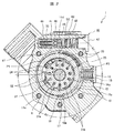
- FIG. 2 is a cross-sectional view showing a II-II cross section of FIG.
- the direction along the rotation axis 14a of the drive shaft 14 is called the direction of the rotation axis 14a
- the left side of FIG. 1 is called the front side and the right side of FIG.
- the front side and the rear side do not mean the front side and the rear side of the vehicle in a state where the variable displacement vane pump is mounted on the vehicle.
- a radial direction (direction perpendicular to the rotation axis 14a) centering on the rotation axis 14a will be simply referred to as a radial direction.
- the outer side in the radial direction is referred to as the outer circumferential side
- the inner side is referred to as the inner circumferential side, with reference to a certain position or object.
- the variable displacement vane pump is, as shown in FIGS. 1 and 2, fitted and mounted in a pump housing consisting of a housing body 11 and a rear body 12 which is a closing member, and a housing space (housing chamber) 10 in a cylindrical portion 5.
- the cam ring 16 which can be pivoted to the left and right in FIG. 2 and the inner peripheral side of the cam ring 16 in the substantially oval space of the adapter ring 15 and the adapter ring 15 are disposed in the pump housing.
- a drive shaft 14 rotatably supported via B2 and a rotor 21 rotatably disposed inside the cam ring 16 and coupled to the drive shaft 14 are provided.
- the pump element comprises an adapter ring 15, a cam ring 16, a rotor 21 and vanes 22.
- the adapter ring 15 is disposed on the outer peripheral side with respect to the cam ring 16, and the cam ring 16 is disposed on the inner peripheral side with respect to the adapter ring 15.
- the rotor 21 has a substantially disk shape, is rotatably accommodated on the inner peripheral side of the cam ring 16, and is rotationally driven by the drive shaft 14.
- the vanes 22 have a rectangular plate shape and are provided radially along the radial direction on the outer peripheral portion of the rotor 21.
- the accommodation space 10 constitutes an accommodation space (pump element accommodation space) of the pump element.
- the pump housing is configured such that a front side housing main body 11 having a bottomed cylindrical portion 5 and a rear side rear body 12 closing the open end of the cylindrical portion 5 are abutted.
- the housing body 11 and the rear body 12 are each formed of an aluminum alloy.
- the housing body 11 constitutes a first housing of the pump housing
- the rear body 12 constitutes a second housing of the pump housing.
- the drive shaft 14 is rotatably supported by a first bearing B1 accommodated in a first bearing accommodation space (first bearing holding hole) 11b provided in the housing main body (first housing) 11 at one end side in the direction of the rotation axis 14a It is done.
- the other end side of the drive shaft 14 is rotatable by a second bearing B2 accommodated in a drive shaft accommodation hole (drive shaft accommodation hole) 12c formed on an end face of the fitting convex portion of the rear body (second housing) 12 It is supported by
- the drive shaft accommodation hole 12c constitutes a second bearing accommodation space (second bearing accommodation hole) for accommodating the second bearing B2.
- the first bearing accommodation space 11 b is provided on one side of the accommodation space 10 in the direction of the rotation axis 14 a of the drive shaft 14.
- the drive shaft accommodation hole 12 c is provided on the other side of the accommodation space 10 in the direction of the rotation axis 14 a of the drive shaft 14.
- Each of the first bearing B1 and the second bearing B2 is formed of a cylindrical bush.
- the outer peripheral surface of the first bearing (bush) B1 is in contact with the inner peripheral surface of the first bearing accommodation space 11b, and the inner peripheral surface is in contact with the outer peripheral surface of the drive shaft.
- the outer peripheral surface of the second bearing (bush) B2 is in contact with the inner peripheral surface of the drive shaft accommodation hole 12c, and the inner peripheral surface is in contact with the outer peripheral surface of the drive shaft 14.
- a bush is a bush demonstrated by FI: F16C33 / 04.
- the housing body 11 constitutes a housing space 10
- the rear body 12 constitutes a lid member for closing the housing space 10.
- the accommodation space 10 has a peripheral wall (inner peripheral surface) 10a along the rotation axis 14a and an end face 10b along the radial direction centering on the rotation axis 14a.
- the peripheral wall 10 a and the end face 10 b form a recess that is concave toward the front side from the rear end face of the housing body 11.
- a bolt female screw hole 11a is formed in which a plurality of (five in the present embodiment) bolts 4 to be coupled with the rear body 12 are screwed in and attached.
- the cylindrical portion 5 holds the cam ring 16 and the rotor 21 in cooperation with the rear body 12 on the end surface (inner bottom surface) 10b side of the bottom portion 11e opposite to the rear open end and holds the pressure plate 23 Is housed.
- the pressure plate 23 is a substantially disk-shaped member made of an iron-based metal material, but may be formed of an aluminum alloy material.
- the rear body 12 integrally has a disk-like projecting portion 12a on the end face on the rotor 21 side, and the projecting portion 12a is fitted to the inner peripheral surface of the opening end of the housing space 10 of the cylindrical portion 5 In some cases, radial positioning of the rear body 12 is performed. Further, a drive shaft receiving hole (drive shaft receiving hole) 12c for rotatably receiving the one end 14b of the drive shaft 14 is formed on the tip end surface 12b side of the protrusion 12a.
- the drive shaft receiving hole (drive shaft receiving hole) 12c is formed along the rotation axis 14a from the front end surface 12b to the opposite side (rear side) to the housing main body 11 side.
- the rear end of the drive shaft receiving hole (drive shaft receiving hole) 12c is closed, and the drive shaft receiving hole (drive shaft receiving hole) 12c is formed as a bottomed recess.
- the bottom side of the drive shaft accommodation hole 12c is in communication with the suction hole 26 via the communication hole 29, whereby the inner peripheral surface of the drive shaft accommodation hole 12c and the outer periphery of one end 14b of the drive shaft 14
- the space between the surfaces is lubricated by the working fluid (hydraulic oil).
- the working fluid leaking from the pump chamber 20 flows into the drive shaft accommodation hole 12c via an axial gap C2 formed between the end face 21d of the rotor 21 on the rear body 12 side and the tip face 12b of the rear body 12 Do.
- the working fluid is supplied to the drive shaft accommodation hole 12c by the communication hole 29 and the axial gap C2, and the working fluid supplied to the drive shaft accommodation hole 12c is the inner peripheral surface of the second bearing (bush) B2 and the drive shaft Lubricate between 14 and the outer peripheral surface.
- the first bearing B1 is generated by the hydraulic oil leaking from the pump chamber 20 via an axial gap C1 formed between the front end face 21c of the rotor 21 and the rear end face 23a of the pressure plate 23 Be lubricated.
- a seal receiving space (seal holding groove) 11c is provided which has a step difference from the first bearing receiving space 11b of the housing body 11 toward the front side to expand the diameter.
- a seal member S1 for sealing the space between the inner peripheral surface of the seal housing space 11c of the housing body 11 and the outer peripheral surface of the drive shaft 14 in a fluid-tight manner is disposed inside the seal housing space 11c. That is, the seal member S1 seals between the drive shaft 14 and the pump housing.
- the adapter ring 15 is integrally formed of an iron-based metal, and as shown in FIG. 2, a position holding pin for holding the position of the cam ring 16 in an arc-shaped support groove formed in the lower part of the elliptical inner circumferential surface 15a. 17 are provided. Further, a plate-like member 18 having a predetermined width is provided in the vicinity of the left side of the position holding pin 17 of the inner circumferential surface 15 a in the drawing, that is, the side of the first fluid pressure chamber P1 described later. It constitutes a rocking fulcrum.
- the position holding pin 17 has a function as a rotation stopper of the cam ring 16 with respect to the adapter ring 15 while holding the position of the cam ring 16 instead of the rocking fulcrum of the cam ring 16.
- the cam ring 16 is substantially annularly formed of an iron-based metal, is disposed in the housing space 10 in an eccentric state with respect to the rotor 21 and is a seal member substantially opposite to the position holding pin 17 A first fluid pressure chamber P1 and a second fluid pressure chamber P2 are separated between the adapter ring 15 and S2 via S2.
- the cam ring 16 is pivotable toward the first fluid pressure chamber P1 or the second fluid pressure chamber P2 with a predetermined position of the support surface (plate-like member) 18 of the adapter ring 15 as a pivot. .
- the first fluid pressure chamber P1 and the second fluid pressure chamber P2 are a pair of spaces formed inside the pump housing and between the cam ring 16 and the housing space 10 in the radial direction centering on the rotation axis 14a. Make up Specifically, the first fluid pressure chamber P1 and the second fluid pressure chamber P2 are formed between the outer periphery of the cam ring 16 and the inner periphery of the adapter ring 15.
- the first fluid pressure chamber P1 is provided on the side where the internal volume decreases when the cam ring 16 moves in the direction in which the amount of eccentricity between the center of the inner peripheral edge of the cam ring 16 and the rotation axis 14a increases.
- the second fluid pressure chamber P2 is provided on the side where the internal volume increases when the cam ring 16 moves in the direction in which the amount of eccentricity between the center of the inner peripheral edge of the cam ring 16 and the rotation axis 14a increases.
- the center of the inner peripheral edge of the cam ring 16 means the center point of the inner peripheral edge of the cam ring 16 in a cross section orthogonal to the rotation axis 14a.
- the rotor 21 is configured to rotate in the direction of the arrow in FIG. 2 (counterclockwise direction) when the drive shaft 14 is rotationally driven by a crankshaft of an internal combustion engine (not shown). That is, the rotor 21 is rotationally driven by the drive shaft 14. Further, a plurality of slits (slots) 21a along the radial direction are formed on the outer peripheral portion of the rotor 21 at equally-spaced positions in the circumferential direction. In each of the slits 21 a, the vanes 22 are radially retained in the direction of the inner peripheral surface 16 a of the cam ring 16 so as to be able to retract and retract.
- the vanes 22 are provided movably in the radial direction in the slit 21 a. Further, a back pressure groove 21b formed to communicate with the slit 21a is formed at the inner peripheral end of each slit 21a. Thus, a substantially circular back pressure chamber 24 is defined at the inner peripheral end of the slit 21a, the boundary being defined by the back pressure groove 21b and the base end (inner peripheral end) of the vane 22. Ru.
- each pump chamber 20 formed by two adjacent vanes 22 are formed.
- the volume of each pump chamber 20 can be increased or decreased by rocking the cam ring 16 with the plate member 18 as a rocking fulcrum.
- a spring 19 which is a biasing member whose one end is supported by a bolt-like spring retainer 13 is disposed.
- the cam ring 16 is always urged by the spring 19 in the direction in which the volume of the first fluid pressure chamber P1 side, that is, the pump chamber 20 is maximized.
- the rear body 12 is provided with an arc-shaped first port 25 in a suction area A1 in which the volume of each pump chamber 20 gradually increases as the rotor 21 rotates.
- the first port 25 constitutes a suction port for drawing the working fluid into the pump chamber 20.
- the first port 25 supplies the working fluid sucked from the reservoir tank to the respective pump chambers 20 via the suction passage 28 and the suction hole 26 partially formed in the rear body 12.
- the first port 25, the suction passage portion 28 and the suction hole 26 are connected to the housing space 10, and constitute a suction passage for supplying the hydraulic fluid (working fluid) to the housing space 10 as the drive shaft 14 rotates.
- the discharge area A2 in which the volume of each pump chamber 20 gradually decreases with the rotation of the rotor 21 is formed.
- the second port 39 constitutes a discharge port for discharging the working fluid from the pump chamber 20.
- the discharge passage connected to the second port 39 is connected to the housing space 10, and constitutes a passage for discharging the hydraulic fluid (working fluid) from the housing space 10 as the drive shaft 14 rotates.
- the second port 39 also constitutes a part of the discharge passage.
- the above-mentioned communication hole 29 constitutes a return passage that brings the drive shaft accommodation hole (second bearing accommodation space) 12c into communication with the suction passage (the first port 25, the suction hole 26, the suction passage portion 28).
- the pressure plate 23 is formed with a suction hole 36 a for communicating the low pressure chamber 37 formed on the end surface 10 b of the cylindrical portion 5 with the first port 25 via the pump chamber 20.
- a discharge hole 31 for communicating the high pressure chamber 35 which is a discharge port formed on the end surface 10 b of the cylindrical portion 5, with the second port 39 via the pump chamber 20. It is formed.
- the working fluid supplied from the first port 25 or the low pressure chamber 37 to the pump chamber 20 is discharged from the pump chamber 20 whose volume is reduced along with the rotation of the rotor 21 to the second port 39 through the discharge hole 31. It is introduced into the high pressure chamber 35.
- the working fluid introduced into the high pressure chamber 35 is fed from a discharge passage (not shown) formed in the pump housing to a hydraulic power cylinder of the power steering apparatus through a pipe.
- the cam ring 16 is formed in an annular shape and provided movably in the housing space 10.
- the cam ring 16 cooperates with the rotor 21 and the plurality of vanes 22 to form a plurality of pump chambers 20.
- the pump chamber 20 located in the suction area A1 which is an area where the volume increases with the rotation of the drive shaft 14, is from the suction passage (the first port 25, the suction hole 26, the suction passage 28)
- the hydraulic fluid is sucked
- the pump chamber 20 located in the discharge area A2 which is an area where the volume decreases with the rotation of the drive shaft 14, discharges the hydraulic fluid to the discharge passage connected to the second port 39.
- the suction area A1 is provided at one place in a predetermined area in the circumferential direction around the rotation axis 14a.
- the discharge area A2 is a predetermined area in the circumferential direction about the rotation axis 14a, and is provided on one side of the suction area A1 in the radial direction opposite to the suction area A1 via the rotation axis 14a.
- a control valve 40 is provided which is directed in the direction perpendicular to the rotation axis 14a.
- the control valve 40 moves the cam ring 16 by controlling the pressure in the first fluid pressure chamber P1, and changes the amount of hydraulic fluid discharged from the discharge area A2 when the rotor 21 makes one rotation. Control.
- the control valve 40 includes a valve body 41, a valve spring 43, a high pressure chamber 44, and an intermediate pressure chamber 45.
- the valve body 41 is slidably accommodated in a valve hole 11 d formed in the housing main body 11.
- the valve spring 43 urges the valve body 41 in the left direction in FIG. 2 so as to contact the plug 42 attached to one end of the opening of the valve hole 11d.
- the high pressure chamber 44 is formed between the plug 42 and the tip of the valve body 41, and the working fluid pressure on the upstream side of the metering orifice (not shown), ie, the working fluid in the high pressure chamber 35 via the discharge passage 33. A part of is introduced.
- the medium pressure chamber 45 accommodates the valve spring 43 and is supplied with the working fluid pressure on the downstream side of the metering orifice.
- control valve 40 moves to the right in FIG. 2 against the biasing force of the valve spring 43. It is configured.
- the first fluid pressure chamber P1 is on the outer peripheral side of the middle portion of the valve body 41 via the connection passage 47 that communicates the first fluid pressure chamber P1 with the valve hole 11d. It is connected to the low pressure chamber 46 formed in The low pressure chamber 46 is connected to a low pressure passage 48 branched from the suction hole 26 as shown in FIG. 1, and a low pressure working fluid in the suction hole 26 (hereinafter referred to as “suction Pressure) is introduced. That is, when the valve body 41 is located on the left side in FIG. 2, the suction pressure is introduced from the low pressure chamber 46 into the first fluid pressure chamber P1.
- discharge pressure high pressure working fluid in the discharge passage 33 is introduced into the first fluid pressure chamber P1.
- a relief valve 49 is formed inside the valve body 41. Then, when the internal pressure of the intermediate pressure chamber 45 reaches a predetermined value or more, that is, when the pressure on the external load side reaches a predetermined value or more, the relief valve 49 is opened to partially lower the working fluid. The air is returned to the suction port 26 through the passage 48. That is, when the operating pressure of the power steering device reaches a predetermined value or more, the relief valve 49 is opened to release the working fluid.
- the second fluid pressure chamber P2 is in communication with the suction hole 26 via the introduction hole (not shown) formed in the pressure plate 23, and the suction side pressure (low pressure) is always introduced.
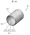
- FIG. 3A is a perspective view showing an appearance of a first bearing according to an embodiment of the present invention.
- the first bearing B1 is formed of a cylindrical bush.
- the first bearing (bush) B1 is provided with a first lubricating groove B1c on a radially inner surface (inner peripheral surface) B1b.
- the outer peripheral surface B1a of the first bearing B1 is provided in the inside of the first bearing accommodation space 11b so as to be in contact with the inner circumferential surface of the first bearing accommodation space (first bearing accommodation hole) 11b. That is, in the first bearing B1, the outer peripheral surface B1a, which is a surface on the outer side in the radial direction centering on the rotation axis 14a, is the inner periphery of the first bearing accommodation space 11b in the entire circumferential direction centering on the rotation axis 14a. It is pressed into the surface.
- the first lubricating groove B1c has a concave shape which is recessed outward in the radial direction from the inner circumferential surface B1b, and is formed of a bottom surface B1c1 and side surfaces B1c2 and B1c3.
- FIG. 3B is a perspective view showing an appearance of a second bearing according to an embodiment of the present invention.
- the second bearing B2 is formed of a cylindrical bush.
- the second bearing (bush) B2 is provided with a second lubricating groove B2c in a radially inner surface (inner peripheral surface) B2b.
- the outer peripheral surface B2a of the second bearing B2 is provided inside the drive shaft accommodation hole 12c so as to contact the inner peripheral surface of the drive shaft accommodation hole (second bearing accommodation hole) 12c which is a second bearing accommodation space.
- the outer peripheral surface B2a which is a surface on the outer side in the radial direction centering on the rotation axis 14a, is press-fit into the inner peripheral surface of the drive shaft accommodation hole 12c in the entire circumferential direction centering on the rotation axis 14a It is done.
- the second lubricating groove B2c has a concave shape which is recessed outward in the radial direction from the inner circumferential surface B2b, and is formed of a bottom surface B2c1 and side surfaces B2c2 and B2c3.
- the second lubricating groove B2c is provided only on the side of the inner circumferential surface B2b that is the inner side in the radial direction centering on the rotation axis 14a.
- the second bearing B2 is constituted by a cylindrical bush.
- the second bearing B2 need not have a cylindrical shape, as long as it supports the drive shaft 14 in a range larger than 180 degrees in the circumferential direction around the rotation axis 14a. In this case, the second bearing B2 can support the drive shaft 14 because the second bearing B2 surrounds a range exceeding the half circumference of the drive shaft 14.
- the first lubricating groove B1c and the second lubricating groove B2c have a cross-sectional area orthogonal to the rotation axis 14a in the second lubricating groove B2c, compared to a cross-sectional area orthogonal to the rotational axis 14a in the first lubricating groove B1c. It is formed large.
- the hydraulic fluid leaked from the pump element passes through the first lubrication groove B1c of the first bearing B1 and reaches the seal member S1.
- the cross-sectional area of the second lubricating groove B2c is made larger than the cross-sectional area of the first lubricating groove B1c, and more hydraulic fluid flows to the second lubricating groove B2c side.
- the hydraulic fluid having flowed to the second lubricating groove B2c side is returned again to the suction passage (the first port 25, the suction hole 26, the suction passage portion 28) through the communication hole 29 which is a return passage. Since no seal member exists in this path, there is little risk of leakage of the hydraulic fluid to the outside of the pump housing even when the flow rate of the hydraulic fluid flowing to the second lubricating groove B2c side is increased.
- the first bearing B1 may have a length LB1 in the direction of the rotation axis 14a longer than a length LB2 in the direction of the rotation axis 14a of the second bearing B2.
- At least the first lubricating groove B1c is formed in a helical shape centered on the rotation axis 14a.
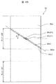
- FIG. 4A is a developed view showing an inner peripheral surface when the inner peripheral surface of the first bearing or the second bearing is expanded in a planar shape.
- the first lubricating groove B1c and the second lubricating groove B2c are formed in a helical shape centered on the rotation axis 14a.
- the flow passage resistance of the first lubricating groove B1c is preferably made larger than the flow passage resistance of the second lubricating groove B2c.
- the inner peripheral surface B1b of the first bearing B1 and the inner peripheral surface B2b of the second bearing B2 are developed in a plane, and a state in which the rotation axis 14a is projected on the developed plane is shown.
- the inclination angle ⁇ of the center line B1CL of the first lubricating groove B1c with respect to the rotation axis 14a may be larger than the inclination angle ⁇ of the center line B2CL of the second lubricating groove B2c.
- the center line B1CL and the center line B2CL are line segments passing through the respective groove centers (the centers in the width direction) of the first lubricating groove B1c and the second lubricating groove B2c.
- the inclination angle ⁇ of the tangents B1c2TL and B1c3TL of the curve drawn by the first lubricating groove B1c is the tangent of the curve drawn by the second lubricating groove B2c, B2c2TL,
- the inclination angle ⁇ of B2c3TL may be set larger.
- the tangential lines B1c2TL and B1c3TL and the tangential lines B2c2TL and B2c3TL are side surfaces B1c2 and B1c3 of the first lubricating groove B1c.
- the side surfaces B2c2 and B2c3 of the second lubricating groove B2c are formed in a linear shape.
- the number of turns of the spiral groove per unit length can be increased, and the flow path of the first lubricating groove B1c The resistance can be further increased.
- FIG. 4B is a developed view showing an inner peripheral surface when the inner peripheral surface of the second bearing is expanded in a planar shape.
- FIG. 4A an example in which the first lubricating groove B1c is provided over the entire circumference of the inner peripheral surface B1b of the first bearing B1, and the second lubricating groove B2c is provided over the entire outer peripheral surface B2b of the second bearing B2 Is shown.
- the second lubricating groove B2c is provided in a range corresponding to the discharge area A2 with the rotation axis 14a as the center.
- the second lubricating groove B2c is provided on the same side as the discharge area A2 in the circumferential direction around the rotation axis 14a.
- the second lubricating groove B2c is not provided in the range corresponding to the suction area A1.
- the central angle ⁇ c at which the second lubricating groove B2c is provided is not limited to 120 °, and can be set arbitrarily within the range of the discharge area A2.
- the drive shaft 14 receives the discharge pressure from the discharge area A2 side toward the suction area A1 side. Therefore, the drive shaft 14 is strongly pressed against the portion on the suction area A1 side in the inner peripheral surface B2b of the second bearing B2. Therefore, the second bearing B2 secures the surface pressure from the drive shaft 14 by increasing the area of the pressure receiving surface without providing the second lubricating groove B2c in the surface on the suction area A1 side where the drive shaft 14 is strongly pressed. I can accept it.
- the pressing force from the drive shaft 14 is small on the discharge area A2 side on the opposite side, the influence is small even if the pressure receiving area is reduced by providing the second lubricating groove B2c.
- the flow volume in 2nd lubricating groove B2c can be increased by enlarging the cross-sectional area of 2nd lubricating groove B2c.
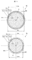
- FIG. 5 is a schematic view showing a cross section of the first bearing, the second bearing, and the drive shaft perpendicular to the rotation axis of the drive shaft.
- an inner diameter Db1 in a radial direction centering on the rotation axis 14a is larger than an inner diameter Db2 of the second bearing B2.
- a pulley or the like is provided on the drive shaft 14 as a drive means, and the drive shaft 14 is pulled in the radial direction. Therefore, although the biasing force from the drive shaft 14 to the first bearing B1 becomes large, the inner pressure Db1 of the first bearing B1 is larger than the inner diameter Db2 of the second bearing B2, so the pressure receiving area becomes larger by that amount. Surface pressure can be suppressed.
- the outer diameter D14a of the portion supported by the first bearing B1 is also larger than the outer diameter D14b of the portion supported by the second bearing B2.
- the dimension Gb1 of the gap between the inner peripheral surface B1b of the first bearing B1 and the outer peripheral surface of the drive shaft 14 in the radial direction about the rotation axis 14a is the inner peripheral surface B2b of the second bearing B2 and the drive shaft 14 Is larger than the dimension Gb2 of the gap between it and the outer circumferential surface thereof.
- the radial clearance between the first bearing B1 and the drive shaft 14 is relatively larger than that of the second bearing B2. For this reason, the flow rate of the hydraulic fluid flowing to the first lubricating groove B1c is also dispersed to the radial clearance side, and the flow velocity of the hydraulic fluid flowing from the first lubricating groove B1c to the seal member S1, in other words, the energy of the hydraulic fluid is reduced can do. As a result, leakage of the hydraulic fluid from the seal member S1 can be suppressed.
- FIG. 6 is a cross-sectional view similar to FIG. 1 showing a modified example in which a partial configuration of the variable displacement vane pump of FIG. 1 is changed.
- a bypass passage 50 is provided in the rear body 12 of the pump housing.
- the bypass passage 50 connects the housing space 10 and the suction passage (the first port 25, the suction hole 26, the suction passage portion 28). Therefore, the hydraulic fluid on the second bearing B2 side can be promptly returned to the suction passage. Therefore, the flow rate of the hydraulic fluid to the first lubricating groove B1c side can be further reduced.
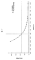
- FIG. 7 is a graph showing a change in impact value relative to the ratio of the groove cross-sectional area of the second bearing to the groove cross-sectional area of the first bearing.
- the impact value changes with respect to the ratio (SB2c / SB1c) of the sectional area SB2c of the second lubricating groove B2c to the sectional area SB1c of the first lubricating groove B1c.
- the rate of decrease decreases and eventually saturates.
- the ratio between the cross-sectional area SB2c and the cross-sectional area SB1c reaches 2.61, the impact value hardly changes even if the ratio between the cross-sectional area SB2c and the cross-sectional area SB1c further increases.
- the first lubricating groove B1c and the second lubricating groove B2c are configured such that the ratio of the cross-sectional area in the orthogonal cross section of the rotation axis 14a of the first lubricating groove B1c and the second lubricating groove B2c satisfies Formula 1 Shall be 2.61 ⁇ (cross sectional area of second lubricating groove B2c) / (cross sectional area of first lubricating groove B1c) (Equation 1)
- the first lubricating groove B1c and the second lubricating groove B2c within the range satisfying the relationship of the equation 1, it is possible to sufficiently obtain the flow rate reduction effect of the hydraulic fluid to the first lubricating groove B1c, and the pump housing Leakage of hydraulic fluid to the outside can be suppressed.
- the present invention is not limited to the above-described embodiment, and deletion of a part of the configuration or addition of another configuration not described is possible. Further, the configurations described in each embodiment can be combined with other embodiments as long as no contradiction arises. By combining the configuration described in each embodiment with another embodiment, the effect exerted by that configuration is also realized in the other embodiments.
- a drive shaft a pump element rotatably driven by the drive shaft, a pump element housing space for housing the pump element therein, and the pump in a direction along the rotation axis of the drive shaft
- a first bearing housing space provided on one side of the element housing space, a second bearing housing space provided on the other side of the pump element housing space in the direction along the rotation axis, and the pump element housing space
- a suction passage which is a passage for supplying the hydraulic fluid to the pump element housing space with the rotation of the drive shaft, is connected to the pump element housing space, and the hydraulic fluid is discharged from the pump element housing space with the rotation of the drive shaft.
- a discharge passage which is a flow passage, a return passage which is a passage connecting the second bearing accommodation space and the suction passage, and a radial direction around the rotation axis.
- a pump housing provided with a seal housing space provided outside the first bearing housing space; and a first lubrication groove, provided inside the first bearing housing space, and supporting the drive shaft
- the second bearing accommodation space includes a first bearing, and a second lubrication groove in which a cross-sectional area of a cross section orthogonal to the rotation axis is larger than a cross-sectional area of a cross section orthogonal to the rotation axis of the first lubrication groove
- a seal member provided inside the seal accommodating space and sealing between the drive shaft and the pump housing.
- the first bearing and the second bearing are bushes, and the second bearing is a drive shaft in a range larger than 180 degrees in a circumferential direction centering on the rotation axis. Support.
- the control valve in any of the aspects of the pump device, the pump element includes a rotor, a plurality of vanes, and a cam ring, and the rotor has the rotation axis
- a plurality of slits are provided in the circumferential direction around the center, and are rotationally driven by the drive shaft, and the plurality of vanes are provided movably in each of the plurality of slits, and the cam ring
- the cam ring, the rotor, and the plurality of vanes are formed annularly and movably in the pump element accommodation space, and the cam ring, the rotor, and the plurality of vanes change a plurality of pump chambers whose volumes change with the rotation of the drive shaft.
- the plurality of pump chambers suck the hydraulic fluid from the suction passage in a suction region, which is a region in which the volume increases as the drive shaft rotates,
- the hydraulic fluid is discharged to the discharge passage in a discharge region which is a region in which the volume decreases with the rotation of the motor, and the suction region is provided in one place in a predetermined region in the circumferential direction about the rotation axis.
- the discharge area is a predetermined area in the circumferential direction centered on the rotation axis, and is provided at one opposite side of the suction area via the rotation axis in a radial direction around the rotation axis
- the pump housing has a first fluid pressure chamber and a second fluid pressure chamber, which are a pair of spaces formed between the cam ring and the peripheral wall of the pump element housing space in the radial direction,
- the first fluid pressure chamber is provided on the side where the internal volume decreases when the cam ring moves in the direction in which the amount of eccentricity between the center of the inner peripheral edge of the cam ring and the rotation axis increases, and the second fluid Pressure Is provided on the side where the internal volume increases when the cam ring moves in the direction in which the eccentricity between the center of the inner peripheral edge of the cam ring and the rotation axis increases, and the control valve is the first fluid
- the cam ring is moved by controlling the pressure in the pressure chamber, and the amount of the hydraulic fluid discharged from the discharge area is variably controlled when
- an outer peripheral surface which is a surface on the outer side in the radial direction centering on the rotation axis is a circumferential direction centering on the rotation axis
- the entire area is press-fit into the second bearing accommodation space, and the second lubrication groove is provided only on the inner circumferential side which is the inner side in the radial direction centering on the rotation axis.
- the length of the first bearing in the direction along the rotation axis is longer than the length of the second bearing in the direction along the rotation axis.
- the first lubrication groove has a helical shape.
- the second lubrication groove has a helical shape, and the inclination angle of the tangent of the first lubrication groove with respect to the rotation axis is the second lubrication groove Greater than the inclination angle of the tangent of.
- the first bearing has an inner diameter in a radial direction centering on the rotation axis, in a radial direction centering on the rotation axis of the second bearing Larger than the inner diameter.
- the dimension of the gap between the first bearing and the outer peripheral surface of the drive shaft in the radial direction centering on the rotation axis is the same in the radial direction It is larger than the dimension of the gap between the second bearing and the outer peripheral surface of the drive shaft.
- the pump housing includes a bypass passage, and the bypass passage connects the pump element accommodation space and the suction passage.
- the first lubrication groove and the second lubrication groove are a cross-sectional area of a cross section orthogonal to the rotation axis of the first lubrication groove and the second lubrication.
- the ratio of the cross-sectional area of the groove to the cross-sectional area of the cross section perpendicular to the rotation axis (the cross-sectional area of the second lubricating groove) / (the cross-sectional area of the first lubricating groove) is greater than 2.61.
Landscapes
- Engineering & Computer Science (AREA)
- Mechanical Engineering (AREA)
- General Engineering & Computer Science (AREA)
- Rotary Pumps (AREA)
- Details And Applications Of Rotary Liquid Pumps (AREA)
Abstract
ポンプ装置は、ポンプ要素を回転駆動する駆動軸を回転可能に支持する第1軸受(B1)と第2軸受(B2)とを備える。第1軸受(B1)は第1潤滑溝(B1c)を有する。第2軸受(B2)は第2潤滑溝(B2c)を有する。第2潤滑溝(B2c)の回転軸線(14a)に対する直交断面の断面積(SB2c)は第1潤滑溝(B1c)の回転軸線(14a)に対する直交断面の断面積(SB1c)よりも大きく形成される。
Description
本発明は、駆動軸に回転駆動されるポンプ要素を有するポンプ装置に関する。
本技術分野の背景技術として、特開2011-127538号公報(特許文献1)に記載された可変容量形ベーンポンプが知られている。
特許文献1の可変容量形ベーンポンプは、駆動軸の一端側が第1ハウジングに設けられた軸受保持部に収容された第1軸受によって回転可能に支持され、他端側が第2ハウジングに設けられた軸受凹部に収容された第2軸受によって回転可能に支持されている(段落0020)。第1軸受と第2軸受とは、ロータの両端面部に形成される軸方向隙間を介してポンプ室から漏出した作動油によって潤滑される。第1軸受を収容する軸受保持部の端部には第1ハウジングの外側に向かって段差を有して拡径するシール保持溝が設けられ、シール保持溝に第1ハウジングの内周面と駆動軸の外周面との間を液密(液体を通さないようにすること)にシールするシール部材が配置されている(段落0021)。
特許文献1の可変容量形ベーンポンプは第1軸受に対して第1ハウジングの外側に向かう側にシール部材を配置し、第1軸受を潤滑する作動油が第1ハウジングの外部に漏れるのを防止している。作動油が高温且つ高圧力になると駆動軸とシール部材との接触部の微小な隙間を通って作動油が第1ハウジングの外部に漏れ易くなる。これに対して、作動油の漏れを防ぐには、高性能或いは複雑な構造を有するシール部材を用いる必要がある。この場合、シール部材のコストが高くなったり、シール部材のサイズが大きくなったりする課題が発生する。或いは、作動油の漏れを防ぐためにシール部材と駆動軸との接触力を大きくすると、駆動軸が受ける摩擦抵抗力が大きくなり、ポンプ装置の効率が低下したり、摩擦による駆動軸の発熱により作動油の温度上昇を招いたりする可能性がある。
本発明の目的は、簡単な構造で作動油の漏れを効果的に抑制できるポンプ装置を提供することにある。
本発明によれば、その一つの態様において、ポンプ装置は以下の構成を備える。
ポンプ装置は、ポンプ要素を回転駆動する駆動軸を回転可能に支持する第1軸受と第2軸受とを備える。第1軸受は第1潤滑溝を有する。第2軸受は第2潤滑溝を有する。第2潤滑溝の回転軸線に対する直交断面の断面積は第1潤滑溝の回転軸線に対する直交断面の断面積よりも大きく形成される。
本発明によれば、簡単な構造で作動油の漏れを効果的に抑制することができる。
以下、本発明にかかる動力伝達軸の支持装置の実施例を図面に基づいて詳述する。なお以下の説明では、ポンプ装置の一実施例として、可変容量形ベーンポンプについて説明する。ポンプ装置は、同様な軸受構造を有する他のポンプ装置であってもよい。また本実施例の可変容量型ベーンポンプは、車両のパワーステアリング装置の油圧源に適用することができる。
図1は、本発明の一実施例に係る可変容量形ベーンポンプの全体について、駆動軸の回転軸線に平行で且つこの回転軸線を含む断面を示す断面図である。図2は、図1のII-II断面を示す断面図である。
本明細書では、駆動軸14の回転軸線14aに沿う方向を回転軸線14a方向と呼び、回転軸線14a方向において図1の左側をフロント側、図1の右側をリア側と呼ぶ。なお、このフロント側及びリア側は、可変容量型ベーンポンプが車両に実装された状態における車両のフロント側及びリア側を意味するものではない。また、回転軸線14aを中心とする径方向(回転軸線14aに垂直な方向)を単に径方向と呼んで説明する。ある位置又は物を基準として、この径方向における外側を外周側、内側を内周側と呼んで説明する。
可変容量型ベーンポンプは、図1及び図2に示すように、ハウジング本体11と閉塞部材であるリアボディ12とからなるポンプハウジングと、筒状部5内の収容空間(収容室)10に嵌めて取り付けられたアダプタリング15と、アダプタリング15のほぼ楕円形の空間内に、図2の左右方向へ揺動可能なカムリング16と、カムリング16の内周側に配置され、ポンプハウジング内に軸受B1,B2を介して回転自在に支持された駆動軸14と、カムリング16の内側に回転自在に配置されて、駆動軸14に結合されたロータ21と、を備えている。
本実施例では、ポンプ要素は、アダプタリング15と、カムリング16と、ロータ21と、ベーン22と、から構成される。アダプタリング15はカムリング16に対して外周側に配置され、カムリング16はアダプタリング15に対して内周側に配置される。ロータ21はほぼ円盤状の形状を成し、カムリング16の内周側に回転自在に収容され、駆動軸14により回転駆動される。ベーン22は矩形板状の形状を成し、ロータ21の外周部に径方向に沿って放射状に設けられる。収容空間10はポンプ要素の収容空間(ポンプ要素収容空間)を構成する。
上記ポンプハウジングは、有底状の筒状部5を有するフロント側のハウジング本体11と、筒状部5の開口端を閉塞するリア側のリアボディ12とを突き合わせた状態で構成されている。ハウジング本体11及びリアボディ12はアルミニウム合金によってそれぞれ形成されている。本実施例では、ハウジング本体11はポンプハウジングの第1ハウジングを構成し、リアボディ12はポンプハウジングの第2ハウジングを構成する。
駆動軸14は、回転軸線14a方向の一端側がハウジング本体(第1ハウジング)11に設けられた第1軸受収容空間(第1軸受保持孔)11bに収容される第1軸受B1によって回転可能に支持されている。一方、駆動軸14の他端側はリアボディ(第2ハウジング)12の嵌合凸部の端面に形成された駆動軸収容穴(駆動軸収容孔)12cに収容される第2軸受B2によって回転可能に支持されている。このように、駆動軸収容穴12cは、第2軸受B2を収容する第2軸受収容空間(第2軸受収容孔)を構成する。
第1軸受収容空間11bは、駆動軸14の回転軸線14a方向において、収容空間10の一方側に設けられている。一方、駆動軸収容穴12cは、駆動軸14の回転軸線14aの方向において、収容空間10の他方側に設けられている。
第1軸受B1及び第2軸受B2はいずれも筒状を成すブッシュにより構成される。第1軸受(ブッシュ)B1の外周面は第1軸受収容空間11bの内周面に接触し、内周面は駆動軸14の外周面に接触している。第2軸受(ブッシュ)B2の外周面は駆動軸収容穴12cの内周面に接触し、内周面は駆動軸14の外周面に接触している。なお、ブッシュは、FI:F16C33/04で説明されるブッシュである。
ハウジング本体11は収容空間10を構成し、リアボディ12は収容空間10を閉じる蓋部材を構成する。収容空間10は、回転軸線14aに沿う周壁(内周面)10aと、回転軸線14aを中心とする径方向に沿う端面10bと、を有する。周壁10aと端面10bとは、ハウジング本体11のリア側端面からフロント側に向かって凹状を成す凹部を形成する。
収容空間10を形成する凹部の開口の周囲には、リアボディ12と結合させる複数本(本実施例では5本)のボルト4がねじ込んで取付けられるボルト雌ねじ穴11aが形成されている。また筒状部5は、リア側の開口端と反対側の底部11eの端面(内底面)10b側にカムリング16とロータ21とをリアボディ12と協働して挟み込んだ状態に保持するプレッシャプレート23を収容している。プレッシャプレート23は鉄系金属材からなるほぼ円盤状の部材であるが、アルミニウム合金材で成形することも可能である。
リアボディ12は、ロータ21側の端面に円盤状の突出部12aを一体に有し、突出部12aが筒状部5の収容空間10の開口端内周面に嵌め合わされて、ハウジング本体11に対する組み付け時にリアボディ12の径方向の位置決めがなされている。また、突出部12aの先端面12b側に駆動軸14の一端部14bを回転自在に収容する駆動軸収容穴(駆動軸収容孔)12cが形成されている。
駆動軸収容穴(駆動軸収容孔)12cは、先端面12bからハウジング本体11側とは反対側(リア側)に向かって、回転軸線14aに沿って形成されている。駆動軸収容穴(駆動軸収容孔)12cのリア側の端部は閉塞されており、駆動軸収容穴(駆動軸収容孔)12cは有底状の凹部として形成されている。先端面12bの駆動軸収容穴12cの外周側(回転軸線14aを中心とする径方向外側)に、後述する各背圧室と連通するほぼ円弧状のベーン背圧溝54,54が径方向の対称位置に形成されている。
駆動軸収容穴12cは、図1に示すように、底部側が連通孔29を介して吸入孔26に連通され、これによって駆動軸収容穴12cの内周面と駆動軸14の一端部14bの外周面との間が作動流体(作動油)によって潤滑される。また駆動軸収容穴12cには、ロータ21のリアボディ12側の端面21dとリアボディ12の先端面12bとの間に形成される軸方向隙間C2を介してポンプ室20から漏れ出した作動流体が流入する。すなわち駆動軸収容穴12cには、連通孔29及び軸方向隙間C2によって作動流体が供給され、駆動軸収容穴12cに供給された作動流体は第2軸受(ブッシュ)B2の内周面と駆動軸14の外周面との間を潤滑する。
一方、第1軸受B1は、ロータ21のフロント側の端面21cとプレッシャプレート23のリア側の端面23aとの間に形成される軸方向隙間C1を介してポンプ室20から漏れ出した作動油により潤滑される。また、かかる構成に伴い、ハウジング本体11の第1軸受収容空間11bからフロント側へ向かって段差を有して拡径するシール収容空間(シール保持溝)11cが設けられている。シール収容空間11cの内部には、ハウジング本体11のシール収容空間11cの内周面と駆動軸14の外周面との間を液密にシールするシール部材S1が配置されている。すなわちシール部材S1は、駆動軸14とポンプハウジングとの間をシールする。これによって、第1軸受B1を潤滑する作動液の外部への漏出が抑制されている。
アダプタリング15は、鉄系金属によって一体に形成され、図2に示すように、楕円形の内周面15aの下部に形成された円弧状の支持溝にカムリング16の位置を保持する位置保持ピン17が設けられている。また、内周面15aの位置保持ピン17の図中左側近傍、つまり後述する第1流体圧室P1側に所定幅を有する板状部材18が設けられており、板状部材18はカムリング16の揺動支点を構成している。なお位置保持ピン17は、カムリング16の揺動支点ではなく、カムリング16の位置を保持しつつアダプタリング15に対するカムリング16の回り止めとしての機能を有する。
カムリング16は、鉄系金属によってほぼ円環状に形成され、ロータ21に対して偏心した状態で収容空間10内に配置されていると共に、位置保持ピン17とこれとほぼ対向した位置にあるシール部材S2を介してアダプタリング15との間に第1流体圧室P1と第2流体圧室P2を隔成している。またカムリング16は、アダプタリング15の支持面(板状部材)18の所定位置を揺動中心として第1流体圧室P1側か、あるいは第2流体圧室P2側へ揺動自在になっている。
第1流体圧室P1と第2流体圧室P2とは、ポンプハウジングの内部であって、回転軸線14aを中心とする径方向においてカムリング16と収容空間10との間に形成される一対の空間を成す。具体的には、第1流体圧室P1と第2流体圧室P2とは、カムリング16の外周とアダプタリング15の内周との間に形成される。
第1流体圧室P1は、カムリング16の内周縁の中心と回転軸線14aとの偏心量が大きくなる方向にカムリング16が移動するとき内部容積が減少する側に設けられている。第2流体圧室P2は、カムリング16の内周縁の中心と回転軸線14aとの偏心量が大きくなる方向にカムリング16が移動するとき内部容積が増大する側に設けられている。なお、カムリング16の内周縁の中心は、回転軸線14aに対する直交断面における、カムリング16の内周縁の中心点を意味する。
ロータ21は、駆動軸14が図外の内燃機関のクランクシャフトによって回転駆動されると、図2の矢印方向(反時計方向)に回転するようになっている。すなわちロータ21は、駆動軸14により回転駆動される。またロータ21の外周部には、円周方向の等間隔位置に放射方向に沿ったスリット(スロット)21aが複数形成されている。この各スリット21a内には、ベーン22がそれぞれカムリング16の内周面16a方向へ放射状に出没自在に保持されている。すなわちベーン22は、スリット21aの中で径方向に移動可能に設けられている。また、各スリット21aの内周側端部には、スリット21aと連通するように形成された背圧溝21bが形成されている。これにより、スリット21aの内周側端部には、背圧溝21bとベーン22の基端部(内周側端部)とによって境界が定められる、ほぼ円形状の背圧室24が構成される。
カムリング16とロータ21との間に形成される空間内には、隣接する二枚のベーン22によって形成されるポンプ室20が複数形成される。カムリング16を、板状部材18を揺動支点として揺動させることによって、各ポンプ室20の容積を増減させることができる。
ハウジング本体11の第2流体圧室P2側には、図2に示すように、ボルト状のスプリングリテーナ13に一端が支持された付勢部材であるスプリング19が配置されている。カムリング16は、スプリング19によって常時第1流体圧室P1側、つまり、ポンプ室20の容積が最大になる方向に付勢されている。
リアボディ12には、ロータ21の回転に伴って各ポンプ室20の容積が漸次拡大する吸入領域A1に円弧状の第1ポート25が形成されている。第1ポート25はポンプ室20に作動流体を吸入する吸入ポートを構成する。第1ポート25は、リアボディ12に一部が形成された吸入通路部28及び吸入孔26を介してリザーバタンクから吸い込んだ作動流体を各ポンプ室20に供給するようになっている。このために第1ポート25、吸入通路部28及び吸入孔26は、収容空間10と繋がっており、駆動軸14の回転に伴い作動液(作動流体)を収容空間10に供給する吸入通路を構成する。
また、リアボディ12の第1ポート25と駆動軸収容穴12cとを挟んだ反対側の位置には、ロータ21の回転に伴って、各ポンプ室20の容積が漸次縮小していく吐出領域A2に円弧状の第2ポート39が形成されている。第2ポート39は、ポンプ室20から作動流体を吐出する吐出ポートを構成する。このために第2ポート39に接続される吐出通路は、収容空間10と繋がっており、駆動軸14の回転に伴い作動液(作動流体)を収容空間10から排出する通路を構成する。第2ポート39も吐出通路の一部を構成する。
なお、上述した連通孔29は、駆動軸収容穴(第2軸受収容空間)12cと吸入通路(第1ポート25、吸入孔26、吸入通路部28)とを連通させる戻し通路を構成する。
プレッシャプレート23は、筒状部5の端面10bに形成された低圧室37と第1ポート25とを、ポンプ室20を介して連通させる吸入孔36aが形成されている。吸入孔36aと径方向反対側の位置には、筒状部5の端面10bに形成された吐出口である高圧室35と第2ポート39とをポンプ室20を介して連通させる吐出孔31が形成されている。
したがって、第1ポート25や低圧室37からポンプ室20に供給された作動流体は、ロータ21の回転に伴って容積が減少したポンプ室20から第2ポート39に吐出されて吐出孔31を介して高圧室35に導入されるようになっている。この高圧室35に導入された作動流体は、ポンプハウジングに形成された図外の吐出通路から配管を介してパワーステアリング装置の油圧パワーシリンダに送られるようになっている。
すなわち本実施例の可変容量形ベーンポンプでは、カムリング16は、環状に形成されて、収容空間10内において移動可能に設けられている。カムリング16は、ロータ21および複数のベーン22と協働して、複数のポンプ室20を形成する。複数のポンプ室20のうち、駆動軸14の回転に伴い容積が増大する領域である吸入領域A1に位置するポンプ室20が吸入通路(第1ポート25、吸入孔26、吸入通路部28)から作動液を吸入し、駆動軸14の回転に伴い容積が減少する領域である吐出領域A2に位置するポンプ室20が作動液を第2ポート39に接続される吐出通路へ吐出する。
吸入領域A1は、回転軸線14aを中心とする周方向の所定領域において1か所設けられている。吐出領域A2は、回転軸線14aを中心とする周方向の所定領域であって、回転軸線14aを介して吸入領域A1の径方向の反対側に1か所設けられている。
ハウジング本体11の上部内には、回転軸線14aと直交する方向に向いた制御バルブ40が設けられている。制御バルブ40は、第1流体圧室P1の内部の圧力を制御することにより、カムリング16を移動させ、ロータ21が1回転する際に前述の吐出領域A2から吐出される作動液の量を可変に制御する。
制御バルブ40は、図2に示すように、弁体41と、バルブスプリング43と、高圧室44と、中圧室45と、を備えている。弁体41は、ハウジング本体11内に形成されたバルブ孔11d内に摺動自在に収容されている。バルブスプリング43は、弁体41をバルブ孔11dの開口側の一端部に取り付けられたプラグ42と突き当てた状態で接するように図2の左方向に付勢する。高圧室44は、プラグ42と弁体41の先端部との間に形成されて、図外のメータリングオリフィスの上流側の作動流体圧、つまり吐出通路33を介して高圧室35内の作動流体の一部が導入される。中圧室45は、バルブスプリング43を収容すると共にメータリングオリフィスの下流側の作動流体圧が導入される。
制御バルブ40は、高圧室44と中圧室45との圧力差が所定値以上に達すると、弁体41がバルブスプリング43の付勢力に抗して図2の右方向へと移動するように構成されている。
弁体41が図2の左側に位置するときは、第1流体圧室P1とバルブ孔11dとを連通する接続通路47を介して、第1流体圧室P1が弁体41の中間部外周側に形成された低圧室46に接続される。この低圧室46は、図1に示すように、吸入孔26から分岐形成された低圧通路48に接続されていて、低圧通路48を介して吸入孔26内の低圧な作動流体(以下、「吸入圧」という)が導入されるようになっている。つまり、弁体41が図2中の左側に位置するとき、第1流体圧室P1には低圧室46から吸入圧が導入されるようになっている。
これに対して、高圧室44と中圧室45の差圧によって弁体41が図2中の右側へ移動した場合には、第1流体圧室P1は低圧室46との連通が遮断されて高圧室44と連通することになる。これにより、第1流体圧室P1には、吐出通路33内の高圧な作動流体(以下、「吐出圧」という)が導入されることとなる。このように、第1流体圧室P1には、低圧室46の吸入圧とメータリングオリフィスの上流側の吐出圧とが選択的に供給されるようになっている。
なお、制御バルブ40には、弁体41の内部にリリーフバルブ49が構成されている。そして、中圧室45の内圧が所定値以上に達したときに、つまり、外部の負荷側の圧力が所定以上に達したときにリリーフバルブ49を開放して、作動流体の一部を、低圧通路48を介して吸入孔26へ還流するようになっている。つまりパワーステアリング装置の作動圧力が所定値以上に達したときに、リリーフバルブ49は開放して作動流体を逃がすようになっている。
一方、第2流体圧室P2は、プレッシャプレート23に形成された導入孔(図示せず)を介して吸入孔26に連通されて常時吸入側の圧力(低圧)が導入されている。
図3Aは、本発明の一実施例に係る第1軸受の外観を示す斜視図である。
第1軸受B1は筒状を成すブッシュにより構成される。第1軸受(ブッシュ)B1は、径方向内側の面(内周面)B1bに第1潤滑溝B1cを備える。第1軸受B1の外周面B1aは、第1軸受収容空間(第1軸受収容孔)11bの内周面に接触するように、第1軸受収容空間11bの内部に設けられている。すなわち、第1軸受B1は、回転軸線14aを中心とする径方向の外側の面である外周面B1aが、回転軸線14aを中心とする周方向の全域において、第1軸受収容空間11bの内周面に圧入されている。第1潤滑溝B1cは内周面B1bから径方向外側に向かって窪んだ凹形状を成し、底面B1c1と側面B1c2,B1c3とにより構成される。
図3Bは、本発明の一実施例に係る第2軸受の外観を示す斜視図である。
第2軸受B2は筒状を成すブッシュにより構成される。第2軸受(ブッシュ)B2は、径方向内側の面(内周面)B2bに第2潤滑溝B2cを備える。第2軸受B2の外周面B2aは、第2軸受収容空間である駆動軸収容穴(第2軸受収容孔)12cの内周面に接触するように、駆動軸収容穴12cの内部に設けられている。第2軸受B2は、回転軸線14aを中心とする径方向の外側の面である外周面B2aが、回転軸線14aを中心とする周方向の全域において、駆動軸収容穴12cの内周面に圧入されている。第2潤滑溝B2cは内周面B2bから径方向外側に向かって窪んだ凹形状を成し、底面B2c1と側面B2c2,B2c3とにより構成される。
第2潤滑溝B2cは、回転軸線14aを中心とする径方向の内側である内周面B2b側にのみ設けられている。これにより、第2軸受B2は、外周面B2aの全周において駆動軸収容穴12cに対し圧入されているため、圧入荷重を確保することができる。
本実施例では、第2軸受B2は、円筒形状のブッシュにより構成している。第2軸受B2は、円筒形状である必要はなく、回転軸線14aを中心とする周方向において、180度よりも大きい範囲において、駆動軸14を支持するものであればよい。この場合、第2軸受B2は、駆動軸14の半周を超える範囲を包囲しているため、駆動軸14を支持することができる。
第1潤滑溝B1cと第2潤滑溝B2cとは、第2潤滑溝B2cにおける回転軸線14aに直交する断面の断面積が、第1潤滑溝B1cにおける回転軸線14aに直交する断面の断面積よりも大きく形成されている。
ポンプ要素から漏洩した作動液は、第1軸受B1の第1潤滑溝B1cを通り、シール部材S1へ到達する。この作動液の液量が多量である場合、シール部材S1のシール性能を超え、作動液がポンプハウジングの外部へ漏洩する虞がある。そこで、第1潤滑溝B1cの断面積よりも、第2潤滑溝B2cの断面積を大きくし、より多くの作動液が第2潤滑溝B2c側へ流れる構造とする。これにより、第1潤滑溝B1c側に流れる作動液の流量が抑制され、ポンプハウジングの外部への作動液の漏洩を抑制することができる。一方、第2潤滑溝B2c側へ流れた作動液は、戻し通路である連通孔29を介して再び吸入通路(第1ポート25、吸入孔26、吸入通路部28)へ戻されることになる。この経路には、シール部材は存在しないため、第2潤滑溝B2c側へ流れる作動液の流量が増加した場合であっても、ポンプハウジングの外部への作動液の漏洩の虞は小さい。
第1軸受B1は、回転軸線14a方向の長さLB1を第2軸受B2の回転軸線14a方向の長さLB2よりも長くするとよい。第1軸受B1の回転軸線14a方向の長さLB1を長くすることで、第1潤滑溝B1cの流路長さが長くなり、流路抵抗が増大する。その結果、第1潤滑溝B1c側の流量の低減を図ることができる。
そこで本実施例では、少なくとも第1潤滑溝B1cは回転軸線14aを中心とする螺旋形状に形成する。
図4Aは、第1軸受又は第2軸受の内周面を平面状に展開した場合の内周面を示す展開図である。
本実施例では、第1潤滑溝B1c及び第2潤滑溝B2cを、回転軸線14aを中心とする螺旋形状に形成している。この場合、第1潤滑溝B1cの流路抵抗を第2潤滑溝B2cの流路抵抗よりも大きくすることが好ましい。
図4Aでは、第1軸受B1の内周面B1b及び第2軸受B2の内周面B2bを平面に展開しており、展開した平面に回転軸線14aを投影した状態を示している。このとき、回転軸線14aに対する第1潤滑溝B1cの中心線B1CLの傾き角θが、第2潤滑溝B2cの中心線B2CLの傾き角θよりも大きくなるようにするとよい。なお、中心線B1CL及び中心線B2CLは第1潤滑溝B1c及び第2潤滑溝B2cのそれぞれの溝中央(幅方向の中央)を通る線分である。もし第1潤滑溝B1c及び第2潤滑溝B2cが曲線を描く場合は、第1潤滑溝B1cが描く曲線の接線B1c2TL,B1c3TLの傾き角θが、第2潤滑溝B2cが描く曲線の接線B2c2TL,B2c3TLの傾き角θよりも大きくなるようにするとよい。
なお図4Aでは、展開図において、第1潤滑溝B1c及び第2潤滑溝B2cは直線状に形成されているため、接線B1c2TL,B1c3TL及び接線B2c2TL,B2c3TLは第1潤滑溝B1cの側面B1c2,B1c3及び第2潤滑溝B2cの側面B2c2,B2c3に一致している。
第1潤滑溝B1cの傾き角θが第2潤滑溝B2cの傾き角θに比べて大きいと、単位長さ当たりの螺旋溝の巻き数を多くすることができ、第1潤滑溝B1cの流路抵抗を更に大きくすることができる。
図4Bは、第2軸受の内周面を平面状に展開した場合の内周面を示す展開図である。
図4Aでは、第1潤滑溝B1cを第1軸受B1の内周面B1bの全周に亘って設け、第2潤滑溝B2cを第2軸受B2の内周面B2bの全周に亘って設ける例を示している。図4Aに対して図4Bでは、回転軸線14aを中心として吐出領域A2に対応する範囲に第2潤滑溝B2cを設けている。なお本実施例では、中心角θc=120°の範囲に第2潤滑溝B2cを設ける例を示している。この場合、第2潤滑溝B2cは、回転軸線14aを中心とする周方向において、吐出領域A2と同じ側に設けられる。なお図4Bにおいて、吸入領域A1に対応する範囲には、第2潤滑溝B2cは設けられていない。第2潤滑溝B2cを設ける中心角θcは120°に限られる訳ではなく、吐出領域A2の範囲内で任意に設定することができる。
可変容量形ベーンポンプにおいて、吸入領域A1と吐出領域A2とが1つずつ設けられているため、駆動軸14は吐出領域A2側から吸入領域A1側に向かって吐出圧を受ける。よって駆動軸14は、第2軸受B2の内周面B2bのうち、吸入領域A1側の部分に強く押し付けられる。そこで、駆動軸14が強く押し付けられる吸入領域A1側の面には第2潤滑溝B2cを設けず、受圧面の面積を大きくすることで、第2軸受B2は駆動軸14からの面圧をしっかり受けとめることができる。一方、逆側の吐出領域A2側においては、駆動軸14からの押し付け力が小さいため、第2潤滑溝B2cを設けることで受圧面積が小さくなっても、その影響は小さい。また、第2潤滑溝B2cの断面積を大きくすることによって、第2潤滑溝B2cにおける流量を増大させることができる。
図5は、第1軸受、第2軸受、及び駆動軸について、駆動軸の回転軸線に垂直な断面を示す概略図である。
本実施例では、第1軸受B1は、回転軸線14aを中心とする径方向における内径Db1が、第2軸受B2の内径Db2よりも大きい。シール部材S1が設けられる第1軸受B1側において、駆動軸14には駆動手段としてプーリ等が設けられ、駆動軸14は径方向に引っ張られる。よって、駆動軸14から第1軸受B1に対する付勢力が大きくなるが、第1軸受B1の内径Db1が第2軸受B2の内径Db2よりも大きいため、その分、受圧面積が大きくなり、単位面積当たりの面圧を抑制することができる。
なお、駆動軸14の外径も、第1軸受B1で支持される部分の外径D14aの方が第2軸受B2で支持される部分の外径D14bよりも大きい。
第1軸受B1の内周面B1bと、回転軸線14aを中心とする径方向における駆動軸14の外周面との間の隙間の寸法Gb1は、第2軸受B2の内周面B2bと駆動軸14の外周面との間の隙間の寸法Gb2よりも大きい。第1軸受B1と駆動軸14との間の径方向クリアランスが第2軸受B2と比べて相対的に大きい。このため、第1潤滑溝B1cに流れる作動液の流量が径方向クリアランス側にも分散し、第1潤滑溝B1cからシール部材S1へ流れる作動液の流速、換言すれば、作動液のエネルギを低減することができる。その結果、シール部材S1からの作動液の漏洩を抑制することができる。
図6は、図1の可変容量形ベーンポンプについて、一部の構成を変更した変更例を図1と同様な断面で示す断面図である。
本実施例では、ポンプハウジングのリアボディ12にバイパス通路50を備えている。バイパス通路50は、収容空間10と吸入通路(第1ポート25、吸入孔26、吸入通路部28)とを繋いでいる。このため、第2軸受B2側の作動液を速やかに上記吸入通路に戻すことができる。このため、第1潤滑溝B1c側への作動液の流量を更に低減することができる。
図7は、第2軸受の溝断面積と第1軸受の溝断面積との比に対する衝撃値の変化を示す図である。
図7に示すように、衝撃値は第2潤滑溝B2cの断面積SB2cと第1潤滑溝B1cの断面積SB1cとの比(SB2c/SB1c)に対して変化する。断面積SB2cと断面積SB1cとの比が大きくなるほど衝撃値は小さくなるものの、減少の割合も小さくなり、やがて飽和する。図7では、断面積SB2cと断面積SB1cとの比が2.61に達すると、断面積SB2cと断面積SB1cとの比が更に増加しても衝撃値はほとんど変化しなくなる。
そのため、第1潤滑溝B1cと第2潤滑溝B2cとは、第1潤滑溝B1cと第2潤滑溝B2cの回転軸線14aの直交断面における断面積の比が、式1を満足するように構成されるものとする。
2.61<(第2潤滑溝B2cの断面積)/(第1潤滑溝B1cの断面積) (式1)
式1の関係を満たす範囲で、第1潤滑溝B1cと第2潤滑溝B2cとを設計することで、第1潤滑溝B1cへの作動液の流量低減効果を充分に得ることができ、ポンプハウジング外部への作動液の漏洩を抑制することができる。
2.61<(第2潤滑溝B2cの断面積)/(第1潤滑溝B1cの断面積) (式1)
式1の関係を満たす範囲で、第1潤滑溝B1cと第2潤滑溝B2cとを設計することで、第1潤滑溝B1cへの作動液の流量低減効果を充分に得ることができ、ポンプハウジング外部への作動液の漏洩を抑制することができる。
なお、本発明は上記した実施例に限定されるものではなく、一部の構成の削除や、記載されていない他の構成の追加が可能である。また各実施例に記載された構成は、矛盾しない範囲において、他の実施例に組み合わせることができる。各実施例に記載された構成が他の実施例に組み合わされることにより、その構成が奏する効果は他の実施例においても実現される。
以上説明した実施形態に基づくポンプ装置としては、例えば以下に述べる態様のものが考えられる。
ポンプ装置は、その一態様として、駆動軸と、前記駆動軸に回転駆動されるポンプ要素と、内部に前記ポンプ要素を収容するポンプ要素収容空間、前記駆動軸の回転軸線に沿う方向において前記ポンプ要素収容空間の一方側に設けられた第1軸受収容空間、前記回転軸線に沿う方向において前記ポンプ要素収容空間の他方側に設けられた第2軸受収容空間、前記ポンプ要素収容空間と繋がっており前記駆動軸の回転に伴い作動液を前記ポンプ要素収容空間に供給する通路である吸入通路、前記ポンプ要素収容空間と繋がっており前記駆動軸の回転に伴い作動液を前記ポンプ要素収容空間から排出する通路である吐出通路、前記第2軸受収容空間と前記吸入通路とを連通させる通路である戻し通路、及び前記回転軸線を中心とする径方向において前記第1軸受収容空間の外側に設けられているシール収容空間、を備えたポンプハウジングと、第1潤滑溝を備え、前記第1軸受収容空間の内部に設けられ、前記駆動軸を支持する第1軸受と、前記回転軸線に対する直交断面の断面積が前記第1潤滑溝の前記回転軸線に対する直交断面の断面積よりも大きく形成されている第2潤滑溝を備え、前記第2軸受収容空間の内部に設けられ、前記駆動軸を支持する第2軸受と、前記シール収容空間の内部に設けられ、前記駆動軸と前記ポンプハウジングとの間をシールするシール部材と、を備える。
前記ポンプ装置の好ましい態様において、前記第1軸受および前記第2軸受はブッシュであり、前記第2軸受は、前記回転軸線を中心とする周方向において、180度よりも大きい範囲において、前記駆動軸を支持する。
別の好ましい態様では、前記ポンプ装置の態様のいずれかにおいて、制御バルブを有し、前記ポンプ要素は、ロータと、複数のベーンと、カムリングと、を有し、前記ロータは、前記回転軸線を中心とする周方向に複数のスリットを有し、前記駆動軸に回転駆動されるものであり、前記複数のベーンは、前記複数のスリットのそれぞれの中で移動可能に設けられており、前記カムリングは、環状に形成されて前記ポンプ要素収容空間内において移動可能に設けられており、前記カムリング、前記ロータおよび前記複数のベーンは、前記駆動軸の回転に伴い容積が変化する複数のポンプ室を形成し、前記複数のポンプ室は、前記駆動軸の回転に伴い容積が増大する領域である吸入領域において前記吸入通路から前記作動液を吸入し、前記駆動軸の回転に伴い容積が減少する領域である吐出領域において前記作動液を前記吐出通路へ吐出し、前記吸入領域は、前記回転軸線を中心とする周方向の所定領域において1か所設けられており、前記吐出領域は、前記回転軸線を中心とする周方向の所定領域であって、前記回転軸線を中心とする径方向において前記回転軸線を介して吸入領域の反対側に1か所設けられており、前記ポンプハウジングは、前記径方向において前記カムリングと前記ポンプ要素収容空間の周壁との間に形成される一対の空間である第1流体圧室と第2流体圧室とを有し、前記第1流体圧室は、前記カムリングの内周縁の中心と前記回転軸線との偏心量が大きくなる方向に前記カムリングが移動するときに内部容積が減少する側に設けられており、前記第2流体圧室は、前記カムリングの内周縁の中心と前記回転軸線との偏心量が大きくなる方向に前記カムリングが移動するときに内部容積が増大する側に設けられており、前記制御バルブは、前記第1流体圧室の内部の圧力を制御することにより、前記カムリングを移動させ、前記ロータが1回転する際に前記吐出領域から吐出される前記作動液の量を可変に制御するものであって、前記第2軸受の前記第2潤滑溝は、前記回転軸線を中心とする周方向において、前記吐出領域と同じ側に設けられている。
別の好ましい態様では、前記ポンプ装置の態様のいずれかにおいて、前記第2軸受は、前記回転軸線を中心とする径方向の外側の面である外周面が前記回転軸線を中心とする周方向の全域において前記第2軸受収容空間に対し圧入されており、前記第2潤滑溝は、前記回転軸線を中心とする径方向の内側である内周側にのみ設けられている。
別の好ましい態様では、前記ポンプ装置の態様のいずれかにおいて、前記第1軸受は、前記回転軸線に沿う方向の長さが、前記第2軸受の前記回転軸線に沿う方向の長さよりも長い。
別の好ましい態様では、前記ポンプ装置の態様のいずれかにおいて、前記第1潤滑溝は、螺旋形状を有する。
別の好ましい態様では、前記ポンプ装置の態様のいずれかにおいて、前記第2潤滑溝は、螺旋形状を有し、前記回転軸線に対する前記第1潤滑溝の接線の傾き角は、前記第2潤滑溝の接線の傾き角よりも大きい。
別の好ましい態様では、前記ポンプ装置の態様のいずれかにおいて、前記第1軸受は、前記回転軸線を中心とする径方向における内径が、前記第2軸受の前記回転軸線を中心とする径方向における内径よりも大きい。
別の好ましい態様では、前記ポンプ装置の態様のいずれかにおいて、前記回転軸線を中心とする径方向における前記第1軸受と前記駆動軸の外周面との間の隙間の寸法が、前記径方向における前記第2軸受と前記駆動軸の外周面との間の隙間の寸法よりも大きい。
別の好ましい態様では、前記ポンプ装置の態様のいずれかにおいて、前記ポンプハウジングは、バイパス通路を備え、前記バイパス通路は、前記ポンプ要素収容空間と前記吸入通路とを繋いでいる。
別の好ましい態様では、前記ポンプ装置の態様のいずれかにおいて、前記第1潤滑溝と前記第2潤滑溝とは、前記第1潤滑溝の前記回転軸線に対する直交断面の断面積と前記第2潤滑溝の前記回転軸線に対する直交断面の断面積との比である(第2潤滑溝の断面積)/(第1潤滑溝の断面積)が2.61よりも大きい。
Claims (11)
- 駆動軸と、
前記駆動軸によって回転駆動されるポンプ要素と、
内部に前記ポンプ要素を収容するポンプ要素収容空間、前記駆動軸の回転軸線に沿う方向において前記ポンプ要素収容空間の一方側に設けられた第1軸受収容空間、前記回転軸線に沿う方向において前記ポンプ要素収容空間の他方側に設けられた第2軸受収容空間、前記ポンプ要素収容空間と繋がっており前記駆動軸の回転に伴い作動液を前記ポンプ要素収容空間に供給する通路である吸入通路、前記ポンプ要素収容空間と繋がっており前記駆動軸の回転に伴い作動液を前記ポンプ要素収容空間から排出する通路である吐出通路、前記第2軸受収容空間と前記吸入通路とを連通させる通路である戻し通路、及び前記回転軸線を中心とする径方向において前記第1軸受収容空間の外側に設けられているシール収容空間、を備えたポンプハウジングと、
第1潤滑溝を備え、前記第1軸受収容空間の内部に設けられ、前記駆動軸を支持する第1軸受と、
前記回転軸線に対する直交断面の断面積が前記第1潤滑溝の前記回転軸線に対する直交断面の断面積よりも大きく形成されている第2潤滑溝を備え、前記第2軸受収容空間の内部に設けられ、前記駆動軸を支持する第2軸受と、
前記シール収容空間の内部に設けられ、前記駆動軸と前記ポンプハウジングとの間をシールするシール部材と、を備えたポンプ装置。 - 請求項1に記載のポンプ装置において、
前記第1軸受および前記第2軸受はブッシュであり、前記第2軸受は、前記回転軸線を中心とする周方向において、180度よりも大きい範囲において、前記駆動軸を支持するポンプ装置。 - 請求項2に記載のポンプ装置において、
制御バルブを有し、
前記ポンプ要素は、ロータと、複数のベーンと、カムリングと、を有し、
前記ロータは、前記回転軸線を中心とする周方向に複数のスリットを有し、前記駆動軸によって回転駆動されるものであり、
前記複数のベーンは、前記複数のスリットのそれぞれの中で移動可能に設けられており、
前記カムリングは、環状に形成されて前記ポンプ要素収容空間内において移動可能に設けられており、
前記カムリング、前記ロータおよび前記複数のベーンは、前記駆動軸の回転に伴い容積が変化する複数のポンプ室を形成し、
前記複数のポンプ室は、前記駆動軸の回転に伴い容積が増大する領域である吸入領域において前記吸入通路から前記作動液を吸入し、前記駆動軸の回転に伴い容積が減少する領域である吐出領域において前記作動液を前記吐出通路へ吐出し、
前記吸入領域は、前記回転軸線を中心とする周方向の所定領域において1か所設けられており、
前記吐出領域は、前記回転軸線を中心とする周方向の所定領域であって、前記回転軸線を中心とする径方向において前記回転軸線を介して吸入領域の反対側に1か所設けられており、
前記ポンプハウジングは、前記径方向において前記カムリングと前記ポンプ要素収容空間の周壁との間に形成される一対の空間である第1流体圧室と第2流体圧室とを有し、
前記第1流体圧室は、前記カムリングの内周縁の中心と前記回転軸線との偏心量が大きくなる方向に前記カムリングが移動するときに内部容積が減少する側に設けられており、
前記第2流体圧室は、前記カムリングの内周縁の中心と前記回転軸線との偏心量が大きくなる方向に前記カムリングが移動するときに内部容積が増大する側に設けられており、
前記制御バルブは、前記第1流体圧室の内部の圧力を制御することにより、前記カムリングを移動させ、前記ロータが1回転する際に前記吐出領域から吐出される前記作動液の量を可変に制御するものであって、
前記第2軸受の前記第2潤滑溝は、前記回転軸線を中心とする周方向において、前記吐出領域と同じ側に設けられているポンプ装置。 - 請求項1に記載のポンプ装置において、
前記第2軸受は、前記回転軸線を中心とする径方向の外側の面である外周面が前記回転軸線を中心とする周方向の全域において前記第2軸受収容空間に対し圧入されており、
前記第2潤滑溝は、前記回転軸線を中心とする径方向の内側である内周側にのみ設けられているポンプ装置。 - 請求項1に記載のポンプ装置において、
前記第1軸受は、前記回転軸線に沿う方向の長さが、前記第2軸受の前記回転軸線に沿う方向の長さよりも長いポンプ装置。 - 請求項5に記載のポンプ装置において、
前記第1潤滑溝は、螺旋形状を有するポンプ装置。 - 請求項6に記載のポンプ装置において、
前記第2潤滑溝は、螺旋形状を有し、
前記回転軸線に対する前記第1潤滑溝の接線の傾き角は、前記第2潤滑溝の接線の傾き角よりも大きいポンプ装置。 - 請求項1に記載のポンプ装置において、
前記第1軸受は、前記回転軸線を中心とする径方向における内径が、前記第2軸受の前記回転軸線を中心とする径方向における内径よりも大きいポンプ装置。 - 請求項8に記載のポンプ装置において、
前記回転軸線を中心とする径方向における前記第1軸受と前記駆動軸の外周面との間の隙間の寸法が、前記径方向における前記第2軸受と前記駆動軸の外周面との間の隙間の寸法よりも大きいポンプ装置。 - 請求項1に記載のポンプ装置において、
前記ポンプハウジングは、バイパス通路を備え、
前記バイパス通路は、前記ポンプ要素収容空間と前記吸入通路とを繋いでいるポンプ装置。 - 請求項1に記載のポンプ装置において、
前記第1潤滑溝と前記第2潤滑溝とは、前記第1潤滑溝の前記回転軸線に対する直交断面の断面積と前記第2潤滑溝の前記回転軸線に対する直交断面の断面積との比である(第2潤滑溝の断面積)/(第1潤滑溝の断面積)が2.61よりも大きいポンプ装置。
Priority Applications (1)
| Application Number | Priority Date | Filing Date | Title |
|---|---|---|---|
| US16/644,887 US11274667B2 (en) | 2017-09-07 | 2018-08-22 | Pump device |
Applications Claiming Priority (2)
| Application Number | Priority Date | Filing Date | Title |
|---|---|---|---|
| JP2017171884A JP7005238B2 (ja) | 2017-09-07 | 2017-09-07 | ポンプ装置 |
| JP2017-171884 | 2017-09-07 |
Publications (1)
| Publication Number | Publication Date |
|---|---|
| WO2019049660A1 true WO2019049660A1 (ja) | 2019-03-14 |
Family
ID=65633885
Family Applications (1)
| Application Number | Title | Priority Date | Filing Date |
|---|---|---|---|
| PCT/JP2018/030899 Ceased WO2019049660A1 (ja) | 2017-09-07 | 2018-08-22 | ポンプ装置 |
Country Status (3)
| Country | Link |
|---|---|
| US (1) | US11274667B2 (ja) |
| JP (1) | JP7005238B2 (ja) |
| WO (1) | WO2019049660A1 (ja) |
Families Citing this family (2)
| Publication number | Priority date | Publication date | Assignee | Title |
|---|---|---|---|---|
| CN116066356A (zh) * | 2023-02-27 | 2023-05-05 | 江铃汽车股份有限公司 | 一种液压助力泵及车辆 |
| JP7847930B2 (ja) * | 2024-03-22 | 2026-04-20 | カヤバ株式会社 | ブッシュ及び液圧回転機 |
Citations (4)
| Publication number | Priority date | Publication date | Assignee | Title |
|---|---|---|---|---|
| JPS4825691B1 (ja) * | 1969-02-26 | 1973-07-31 | ||
| JPH07279871A (ja) * | 1994-04-04 | 1995-10-27 | Showa:Kk | オイルポンプの駆動軸枢支構造 |
| JPH09166094A (ja) * | 1995-12-14 | 1997-06-24 | Jidosha Kiki Co Ltd | オイルポンプ |
| JP2001107879A (ja) * | 1999-10-08 | 2001-04-17 | Tokyo Seiko Kk | 歯車ポンプ |
Family Cites Families (5)
| Publication number | Priority date | Publication date | Assignee | Title |
|---|---|---|---|---|
| DE2507253C3 (de) * | 1975-02-20 | 1979-04-26 | Volkswagenwerk Ag, 3180 Wolfsburg | Einrichtung zur Unterdrückung störender Biegeschwingungen bei einer Anordnung mit einer gelagerten gestreckten Welle |
| US5538400A (en) * | 1992-12-28 | 1996-07-23 | Jidosha Kiki Co., Ltd. | Variable displacement pump |
| US5938344A (en) * | 1997-03-26 | 1999-08-17 | Sabin; Jeffrey M. | Temperature compensating bearing |
| JP4769126B2 (ja) * | 2006-05-30 | 2011-09-07 | 株式会社ショーワ | 可変容量型ポンプ |
| JP4922386B2 (ja) | 2009-12-18 | 2012-04-25 | 日立オートモティブシステムズ株式会社 | 可変容量形ベーンポンプ |
-
2017
- 2017-09-07 JP JP2017171884A patent/JP7005238B2/ja not_active Expired - Fee Related
-
2018
- 2018-08-22 US US16/644,887 patent/US11274667B2/en active Active
- 2018-08-22 WO PCT/JP2018/030899 patent/WO2019049660A1/ja not_active Ceased
Patent Citations (4)
| Publication number | Priority date | Publication date | Assignee | Title |
|---|---|---|---|---|
| JPS4825691B1 (ja) * | 1969-02-26 | 1973-07-31 | ||
| JPH07279871A (ja) * | 1994-04-04 | 1995-10-27 | Showa:Kk | オイルポンプの駆動軸枢支構造 |
| JPH09166094A (ja) * | 1995-12-14 | 1997-06-24 | Jidosha Kiki Co Ltd | オイルポンプ |
| JP2001107879A (ja) * | 1999-10-08 | 2001-04-17 | Tokyo Seiko Kk | 歯車ポンプ |
Also Published As
| Publication number | Publication date |
|---|---|
| US20200284255A1 (en) | 2020-09-10 |
| US11274667B2 (en) | 2022-03-15 |
| JP2019044747A (ja) | 2019-03-22 |
| JP7005238B2 (ja) | 2022-01-21 |
Similar Documents
| Publication | Publication Date | Title |
|---|---|---|
| US9534596B2 (en) | Variable displacement pump | |
| EP2946113B1 (en) | Variable displacement pump with multiple pressure chambers | |
| US7993116B2 (en) | Variable displacement vane pump | |
| JP5690238B2 (ja) | 可変容量形オイルポンプ | |
| KR20080094087A (ko) | 감소된 회전자 조립체 직경을 갖는 베인 펌프 | |
| RU2480627C1 (ru) | Лопастной насос | |
| JP6165019B2 (ja) | ベーンポンプ | |
| US20190338771A1 (en) | Variable displacement pump | |
| JPWO2017013932A1 (ja) | ポンプ装置 | |
| US20150252802A1 (en) | Variable displacement vane pump | |
| US8690557B2 (en) | Variable displacement vane pump | |
| US20200080555A1 (en) | Variable Displacement Pump | |
| JP2019044747A (ja) | ポンプ装置 | |
| US9885356B2 (en) | Variable displacement pump | |
| WO2019054139A1 (ja) | ポンプ装置 | |
| JP2000170683A (ja) | 渦流式ポンプ | |
| JP2012163040A (ja) | ベーンポンプ | |
| JP5475701B2 (ja) | ベーンポンプ | |
| JP2016156367A (ja) | 可変容量形ベーンポンプ | |
| JP6243262B2 (ja) | 可変容量形ベーンポンプ | |
| CN111630276A (zh) | 泵装置 | |
| JP6711528B2 (ja) | 可変容量形ポンプ | |
| WO2021166683A1 (ja) | ポンプ装置 | |
| WO2017154490A1 (ja) | 可変容量形ベーンポンプ | |
| JPH09166094A (ja) | オイルポンプ |
Legal Events
| Date | Code | Title | Description |
|---|---|---|---|
| 121 | Ep: the epo has been informed by wipo that ep was designated in this application |
Ref document number: 18854313 Country of ref document: EP Kind code of ref document: A1 |
|
| NENP | Non-entry into the national phase |
Ref country code: DE |
|
| 122 | Ep: pct application non-entry in european phase |
Ref document number: 18854313 Country of ref document: EP Kind code of ref document: A1 |