WO2019049549A1 - 磁気共鳴イメージング装置およびノイズ除去方法 - Google Patents
磁気共鳴イメージング装置およびノイズ除去方法 Download PDFInfo
- Publication number
- WO2019049549A1 WO2019049549A1 PCT/JP2018/028301 JP2018028301W WO2019049549A1 WO 2019049549 A1 WO2019049549 A1 WO 2019049549A1 JP 2018028301 W JP2018028301 W JP 2018028301W WO 2019049549 A1 WO2019049549 A1 WO 2019049549A1
- Authority
- WO
- WIPO (PCT)
- Prior art keywords
- image
- noise
- magnetic resonance
- unit
- separated
- Prior art date
- Legal status (The legal status is an assumption and is not a legal conclusion. Google has not performed a legal analysis and makes no representation as to the accuracy of the status listed.)
- Ceased
Links
- 0 CC(CCC1CCC2**C2)C(CC2)(C(C)(C)C3CCC3)C12C(CC1)(CC2CCC3*4C3C4)C12C(C)(C)C1CC1 Chemical compound CC(CCC1CCC2**C2)C(CC2)(C(C)(C)C3CCC3)C12C(CC1)(CC2CCC3*4C3C4)C12C(C)(C)C1CC1 0.000 description 3
Images


Classifications
-
- G—PHYSICS
- G06—COMPUTING OR CALCULATING; COUNTING
- G06T—IMAGE DATA PROCESSING OR GENERATION, IN GENERAL
- G06T5/00—Image enhancement or restoration
- G06T5/70—Denoising; Smoothing
-
- G—PHYSICS
- G01—MEASURING; TESTING
- G01R—MEASURING ELECTRIC VARIABLES; MEASURING MAGNETIC VARIABLES
- G01R33/00—Arrangements or instruments for measuring magnetic variables
- G01R33/20—Arrangements or instruments for measuring magnetic variables involving magnetic resonance
- G01R33/44—Arrangements or instruments for measuring magnetic variables involving magnetic resonance using nuclear magnetic resonance [NMR]
- G01R33/48—NMR imaging systems
- G01R33/54—Signal processing systems, e.g. using pulse sequences ; Generation or control of pulse sequences; Operator console
- G01R33/56—Image enhancement or correction, e.g. subtraction or averaging techniques, e.g. improvement of signal-to-noise ratio and resolution
- G01R33/5608—Data processing and visualization specially adapted for MR, e.g. for feature analysis and pattern recognition on the basis of measured MR data, segmentation of measured MR data, edge contour detection on the basis of measured MR data, for enhancing measured MR data in terms of signal-to-noise ratio by means of noise filtering or apodization, for enhancing measured MR data in terms of resolution by means for deblurring, windowing, zero filling, or generation of gray-scaled images, colour-coded images or images displaying vectors instead of pixels
-
- A—HUMAN NECESSITIES
- A61—MEDICAL OR VETERINARY SCIENCE; HYGIENE
- A61B—DIAGNOSIS; SURGERY; IDENTIFICATION
- A61B5/00—Measuring for diagnostic purposes; Identification of persons
- A61B5/05—Detecting, measuring or recording for diagnosis by means of electric currents or magnetic fields; Measuring using microwaves or radio waves
- A61B5/055—Detecting, measuring or recording for diagnosis by means of electric currents or magnetic fields; Measuring using microwaves or radio waves involving electronic [EMR] or nuclear [NMR] magnetic resonance, e.g. magnetic resonance imaging
-
- G—PHYSICS
- G01—MEASURING; TESTING
- G01R—MEASURING ELECTRIC VARIABLES; MEASURING MAGNETIC VARIABLES
- G01R33/00—Arrangements or instruments for measuring magnetic variables
- G01R33/20—Arrangements or instruments for measuring magnetic variables involving magnetic resonance
- G01R33/44—Arrangements or instruments for measuring magnetic variables involving magnetic resonance using nuclear magnetic resonance [NMR]
- G01R33/48—NMR imaging systems
- G01R33/483—NMR imaging systems with selection of signals or spectra from particular regions of the volume, e.g. in vivo spectroscopy
- G01R33/4833—NMR imaging systems with selection of signals or spectra from particular regions of the volume, e.g. in vivo spectroscopy using spatially selective excitation of the volume of interest, e.g. selecting non-orthogonal or inclined slices
- G01R33/4835—NMR imaging systems with selection of signals or spectra from particular regions of the volume, e.g. in vivo spectroscopy using spatially selective excitation of the volume of interest, e.g. selecting non-orthogonal or inclined slices of multiple slices
-
- G—PHYSICS
- G01—MEASURING; TESTING
- G01R—MEASURING ELECTRIC VARIABLES; MEASURING MAGNETIC VARIABLES
- G01R33/00—Arrangements or instruments for measuring magnetic variables
- G01R33/20—Arrangements or instruments for measuring magnetic variables involving magnetic resonance
- G01R33/44—Arrangements or instruments for measuring magnetic variables involving magnetic resonance using nuclear magnetic resonance [NMR]
- G01R33/48—NMR imaging systems
- G01R33/54—Signal processing systems, e.g. using pulse sequences ; Generation or control of pulse sequences; Operator console
- G01R33/56—Image enhancement or correction, e.g. subtraction or averaging techniques, e.g. improvement of signal-to-noise ratio and resolution
- G01R33/561—Image enhancement or correction, e.g. subtraction or averaging techniques, e.g. improvement of signal-to-noise ratio and resolution by reduction of the scanning time, i.e. fast acquiring systems, e.g. using echo-planar pulse sequences
- G01R33/5611—Parallel magnetic resonance imaging, e.g. sensitivity encoding [SENSE], simultaneous acquisition of spatial harmonics [SMASH], unaliasing by Fourier encoding of the overlaps using the temporal dimension [UNFOLD], k-t-broad-use linear acquisition speed-up technique [k-t-BLAST], k-t-SENSE
-
- G—PHYSICS
- G06—COMPUTING OR CALCULATING; COUNTING
- G06T—IMAGE DATA PROCESSING OR GENERATION, IN GENERAL
- G06T5/00—Image enhancement or restoration
- G06T5/50—Image enhancement or restoration using two or more images, e.g. averaging or subtraction
-
- G—PHYSICS
- G01—MEASURING; TESTING
- G01R—MEASURING ELECTRIC VARIABLES; MEASURING MAGNETIC VARIABLES
- G01R33/00—Arrangements or instruments for measuring magnetic variables
- G01R33/20—Arrangements or instruments for measuring magnetic variables involving magnetic resonance
- G01R33/44—Arrangements or instruments for measuring magnetic variables involving magnetic resonance using nuclear magnetic resonance [NMR]
- G01R33/48—NMR imaging systems
- G01R33/54—Signal processing systems, e.g. using pulse sequences ; Generation or control of pulse sequences; Operator console
- G01R33/546—Interface between the MR system and the user, e.g. for controlling the operation of the MR system or for the design of pulse sequences
-
- G—PHYSICS
- G01—MEASURING; TESTING
- G01R—MEASURING ELECTRIC VARIABLES; MEASURING MAGNETIC VARIABLES
- G01R33/00—Arrangements or instruments for measuring magnetic variables
- G01R33/20—Arrangements or instruments for measuring magnetic variables involving magnetic resonance
- G01R33/44—Arrangements or instruments for measuring magnetic variables involving magnetic resonance using nuclear magnetic resonance [NMR]
- G01R33/48—NMR imaging systems
- G01R33/54—Signal processing systems, e.g. using pulse sequences ; Generation or control of pulse sequences; Operator console
- G01R33/56—Image enhancement or correction, e.g. subtraction or averaging techniques, e.g. improvement of signal-to-noise ratio and resolution
- G01R33/565—Correction of image distortions, e.g. due to magnetic field inhomogeneities
- G01R33/56545—Correction of image distortions, e.g. due to magnetic field inhomogeneities caused by finite or discrete sampling, e.g. Gibbs ringing, truncation artefacts, phase aliasing artefacts
-
- G—PHYSICS
- G06—COMPUTING OR CALCULATING; COUNTING
- G06T—IMAGE DATA PROCESSING OR GENERATION, IN GENERAL
- G06T2207/00—Indexing scheme for image analysis or image enhancement
- G06T2207/10—Image acquisition modality
- G06T2207/10072—Tomographic images
- G06T2207/10088—Magnetic resonance imaging [MRI]
-
- G—PHYSICS
- G06—COMPUTING OR CALCULATING; COUNTING
- G06T—IMAGE DATA PROCESSING OR GENERATION, IN GENERAL
- G06T2207/00—Indexing scheme for image analysis or image enhancement
- G06T2207/20—Special algorithmic details
- G06T2207/20024—Filtering details
- G06T2207/20028—Bilateral filtering
-
- G—PHYSICS
- G06—COMPUTING OR CALCULATING; COUNTING
- G06T—IMAGE DATA PROCESSING OR GENERATION, IN GENERAL
- G06T2207/00—Indexing scheme for image analysis or image enhancement
- G06T2207/20—Special algorithmic details
- G06T2207/20024—Filtering details
- G06T2207/20032—Median filtering
Definitions
- the present invention relates to magnetic resonance imaging (MRI) technology.
- the present invention relates to an image processing technique for removing noise of an image obtained by separating spatially overlapped signals in an image acquired using a plurality of receiving coils.
- a magnetic resonance imaging (MRI) apparatus is a non-invasive medical imaging diagnostic apparatus using nuclear magnetic resonance phenomenon in which hydrogen nuclei (protons) placed in a static magnetic field resonate with a high frequency magnetic field of a specific frequency.
- MRI can capture images of various tissue contrasts by imaging methods and imaging parameter changes, so it is possible to acquire information on biological functions such as blood flow and metabolic functions as well as morphological information, and a diagnostic device that is essential in the field of diagnostic imaging It has become.
- Methods for shortening imaging time in MRI include a method of scanning k-space at high speed such as Echo Planar Imaging (EPI) and Fast Spin Echo (FSE), SENSE method (for example, Non-Patent Document 1) and GRAPPA method (for example).
- EPI Echo Planar Imaging
- FSE Fast Spin Echo
- SENSE method for example, Non-Patent Document 1
- GRAPPA method for example.
- Non-Patent Document 2 there is a method of measuring a small number of points in the k space and restoring an unmeasured point by signal processing.
- a method of shortening the imaging time in two-dimensional (2D) multi-slice measurement there is a method of simultaneously imaging a plurality of slices as in the CAIPIRINHA method (for example, non-patent document 3) and separating overlapping signals by signal processing. is there.
- the EPI method and the FSE method are susceptible to static magnetic field inhomogeneity, T2 attenuation and the like as well as limited image contrast to be obtained.
- the SENSE method, the GRAPPA method, and the CAIPIRINHA method (hereinafter, these methods are collectively referred to as Parallel Imaging (PI) method) are characterized in that the imaging time can be shortened without depending on the imaging sequence.
- the PI method spatially overlapped signals are acquired by a plurality of receiving coils, and differences in sensitivity distribution among the receiving coils are used to separate the spatially overlapped signals.
- SNR signal-to-noise ratio
- g-factor Geometry factor
- Non-Patent Document 4 a noise removal method using regularization
- Patent Document 1 a noise removal method in which a reference image and regularization are combined
- Pruessmann KP et al. "SENSE: Sensitivity Encoding for Fast MRI", Magnetic Resonance in Medicine, 1999, 42, 952-962.
- Griswold MA et al. "Generalized Autocalibration Partially Parallel Acquisitions (GRAPPA)", Magnetic Resonance in Medicine, 2002, 47, 1202-1210.
- Felix AB et al. “Controlled Aliasing in Parallel Imaging Results in Higher Acceleration (CAIPIRINHA) for Multi-Slice Imaging”, Magnetic Resonance in Medicine, 2005, 53, 684-691.
- King KF et al. "SENSE Image Quality Improvement Using Matrix Regularization", In Proceedings of the 9th Annual Meeting of ISMRM, Glasgow, Scotland, 2001, 1771.
- Non-Patent Document 4 separates the sensitivity of spatially overlapped signals using prior information called zeroth order regularization and the difference in sensitivity distribution among the receiving coils. By combining the above, a separated image with reduced noise is obtained.
- the method of Non-Patent Document 4 has a problem that the noise reduction effect is low because the prior information included in the regularization does not represent characteristics between spatially overlapped signals.
- Patent Document 1 uses a difference in sensitivity distribution between a spatially overlapped signal, a priori information called Tikhonov regularization, a spatially non-overlapping reference image, and a receiving coil, and the sensitivity distribution. By combining the separation processing, a separated image with reduced noise is obtained.
- the method of Patent Document 1 has a problem that the imaging time is extended since it is necessary to measure in advance a reference image having no spatial overlap separately from the reception sensitivity distribution.
- the present invention has been made in view of the above circumstances, and in an image acquired using a plurality of receiving coils, noise of a separated image obtained by separating spatially overlapped signals using PI method is added as an additional reference image To provide a removal technique without the need for
- the present invention separates spatially overlapped signals from nuclear magnetic resonance signals received by a plurality of receiving coils using sensitivity distributions of the plurality of receiving coils to calculate a plurality of separated images. Then, noise is removed based on the correlation of noise mixed in the separated images.
- the spatially overlapped signal means a signal (superimposed signal) in a state in which signals from different positions can not be distinguished only from the signal.
- the spatially superimposed signal in the present specification includes not only the superimposed signal in the image space but also a k-space signal that becomes a spatially superimposed signal when the image is reconstructed.
- the MRI apparatus comprises a transmitter configured to transmit a high frequency magnetic field pulse to a subject placed in a static magnetic field, a receiver configured to receive a nuclear magnetic resonance signal generated by the subject by a plurality of receiving coils, A measurement unit having a gradient magnetic field generation unit that gives a gradient magnetic field to a static magnetic field, and a computer that performs an operation on the received nuclear magnetic resonance signal, the computer is a nuclear magnetic resonance signal received by the plurality of receiving coils. And an image generation unit that generates a plurality of separated images having no spatial overlap with each other based on the sensitivity information of the plurality of receiving coils, and the correlation of noise mixed between the separated images. And a noise removing unit that removes noise from the separated image.
- a high quality image from which noise has been removed can be calculated without performing imaging of a reference image or the like for removing noise. As a result, the extension of the imaging time as a whole can be prevented, and the diagnostic accuracy is improved.
- FIG. 6 is a diagram for explaining noise correlation, in which (a) shows the noise correlation of the real part of the complex image, and (b) shows the noise correlation of the imaginary part of the complex image.
- Diagram showing an example of a UI for selecting a noise removal method Functional block diagram of the computer of the first embodiment
- the figure which shows the flow of the processing by the computer of 1st embodiment A diagram showing an example of a pulse sequence employed in the first embodiment
- Functional block diagram of the computer of the second embodiment (A) is a figure which shows an example of the pulse sequence employ
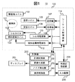
- the measuring unit 100 that measures nuclear magnetic resonance signals generated from the subject 101 is roughly divided, and the measuring unit 100 controls the measuring unit 100 while measuring the nuclear magnetic resonance signal.
- a computer 200 for performing image reconstruction, correction and other operations using the nuclear magnetic resonance signal is roughly divided, and the measuring unit 100 controls the measuring unit 100 while measuring the nuclear magnetic resonance signal.
- the measurement unit 100 includes a static magnetic field coil 102 that generates a static magnetic field in a space in which the subject 101 is placed, and a transmission unit (105, 107) that transmits high frequency magnetic field pulses to the subject 101 disposed in the static magnetic field.
- the static magnetic field coil 102 is composed of a normal conducting or superconducting static magnetic field coil, a static magnetic field generating magnet, etc., and depending on the direction of the generated static magnetic field, there are vertical magnetic field type and horizontal magnetic field type etc. And the overall appearance of the device is different.
- FIGS. 2 (a) to 2 (c) show the appearances of MRI apparatuses different in these methods. The present embodiment is applicable to any of the illustrated MRI apparatuses.
- the transmission unit includes a transmission high-frequency coil 105 (hereinafter simply referred to as a transmission coil) for transmitting a high-frequency magnetic field to the measurement region of the subject 101, and a transmitter 107 provided with a high-frequency oscillator, an amplifier and the like.
- the receiving unit includes a receiving high-frequency coil 106 (hereinafter simply referred to as a receiving coil) for receiving a nuclear magnetic resonance signal generated from the subject 101, and a receiver 108 including an orthogonal detection circuit, an A / D converter, and the like.
- the receiving coil is composed of a plurality of channels (small receiving coils), and a quadrature detection circuit and an A / D converter constituting the receiver 108 are connected to each of them.
- the nuclear magnetic resonance signal received by the receiver 108 is passed to the computer 200 as a complex digital signal.
- spatially overlapping signals are measured and separated in the reconstructed image.
- the sensitivity distribution of the receiving coil that receives the magnetic resonance signal generated from the subject 101 is used.
- the number of receiving coils 106 is at least equal to or more than the number of signals to be separated.
- the gradient magnetic field coil 103 has three sets of gradient magnetic field coils that apply gradient magnetic fields in the x direction, y direction, and z direction, respectively, and is connected to the gradient magnetic field power supply unit 112.
- the MRI apparatus may further include shim coils 104 for adjusting the static magnetic field distribution and a shim power supply unit 113 for driving the same.
- the measurement unit 100 further includes a sequence control device 114 that controls the operation of the measurement unit 100.
- the sequence control device 114 controls the operations of the gradient power supply unit 112, the transmitter 107, and the receiver 108, and controls the timing of application of the gradient magnetic field, the high frequency magnetic field, and the reception of the nuclear magnetic resonance signal.
- the time chart of control is called a pulse sequence, is preset according to the measurement, and is stored in a storage device or the like provided in the computer 200 described later.
- the computer 200 controls the overall operation of the MRI apparatus 100 and performs various arithmetic processing on the received nuclear magnetic resonance signal.
- the computer 200 is an information processing apparatus provided with a CPU, a memory, a storage device and the like, and the computer 200 is connected to a display 201, an external storage device 203, an input device 205 and the like.
- the display 201 is an interface that displays the result obtained by the arithmetic processing to the operator.
- the input device 205 is an interface for the operator to input conditions, parameters, and the like necessary for measurement and arithmetic processing performed in the present embodiment.
- the user can input measurement parameters such as, for example, double speed in the PI method via the input device 205.
- the external storage device 203 holds, in addition to a storage device inside the computer 200, data used for various types of arithmetic processing executed by the computer 200, data obtained by the arithmetic processing, input conditions, parameters, and the like.
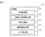
- the computer 200 generates the sensitivity distribution of the receiving coil, the separated image, the noise removed image, and the like. Therefore, as shown in FIG. 1, the computer 200 includes functional units such as a measurement control unit 210, an image generation unit 230, a noise removal unit 270, and a display control unit 290.
- the functions of these units can be realized as software incorporated in the computer 200, and are realized by the CPU loading a program (software) held by the storage device into the memory and executing the program.
- Various data used for processing of each function and various data generated during processing are stored in the storage device or the external storage device 203.
- At least one of the various functions realized by the computer 200 is an information processing apparatus independent of the MRI apparatus 10 and realized by an information processing apparatus capable of transmitting and receiving data with the MRI apparatus 100. It may be Furthermore, all or part of the functions may be realized by hardware such as an application specific integrated circuit (ASIC) or a field-programmable gate array (FPGA).
- ASIC application specific integrated circuit
- FPGA field-programmable gate array
- the imaging sequence is not particularly limited, but in the present embodiment, an imaging method (PI method) for measuring spatially overlapping signals is selected and set in order to shorten the imaging time.
- the imaging conditions include the parameters of the imaging sequence (the repetition time TR, the echo time TE), and include the thinning rate when performing the thinning measurement of the k space. Also, in the case of simultaneous slice-excitation (SMS: Simultaneous Multi-Slice), the setting of the number of slices is included.
- SMS simultaneous slice-excitation
- the number of slices is included.
- the spatially overlapped signal means a signal which is overlapped by signals from different positions in the real space without being encoded by the gradient magnetic field, and the spatially overlapped signal (including so-called aliasing) is obtained by undersampling. Signals) and signals from simultaneous excitation multi slice (SMS). What kind of "spatially overlapped signal" depends on the measurement method.
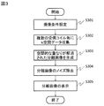
- the measurement control unit 210 operates the sequence control device 114 according to a pulse sequence set based on the parameter input by the user, and measures a nuclear magnetic resonance signal (echo signal) under a predetermined condition.
- the sequence control device 114 controls the respective units of the MRI device 100 according to the instruction from the measurement control unit 210, and measures spatially overlapping signals in order to shorten the imaging time (S302). That is, k-space data is collected for each receiving coil.
- the image generation unit 230 separates spatially overlapped signals by using k-space data for each reception coil and sensitivity distributions of a plurality of reception coils, and generates an image at a spatially different position (referred to as a separated image). Are formed (S303).
- the noise removal unit 270 removes noise based on the correlation of noise included in each separated image (S304).
- the noise removal is realized by performing an iterative operation so as to minimize noise under predetermined constraints, as in the well-known nonlinear filter including TotalVariation regularization and sparse regularization.
- the noise removal unit 270 in the form performs repetitive calculation including the correlation of noise between separated images as a constraint condition.
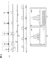
- FIGS. 4A and 4B are the results of plotting the signals of the real part and the imaginary part of the two separated images 1 1 and 2 2 with the horizontal axis ⁇ 1 and the vertical axis ⁇ 2 . As shown in FIG.
- the images 1 1 and ⁇ 2 after separating the complex noise image have negative correlation with respect to both the real part and the imaginary part. That is, it can be seen that the variance of the sum of the separated images 1 1 and ⁇ 2 is smaller than the variance before separation.
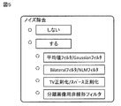
- the display control unit 290 displays a UI as shown in FIG. 5 on the display 201.
- a known noise removal method for example, a linear filter such as an average value filter or a Gaussian filter, an edge preserving filter such as a Bilateral filter, a nonlinear filter including TotalVariation regularization or sparse regularization, etc. It is possible to select the noise removal method of This gives the user more freedom in selecting the method.
- the separated image after noise removal is stored in the storage device 203 or displayed on the display 201 as necessary (S305).
- a plurality of receiving coils are used to obtain spatially overlapping signals, and the sensitivity distribution of each receiving coil is used to obtain a plurality of images (separate images) having no spatial overlap.
- the noise correlation between the separated images is used as a constraint to remove the noise of the separated images.
- the present embodiment employs a 2D parallel imaging method of undersampling in the phase encoding direction.
- spatially overlapping signals are separated by the SENSE method. That is, a separated image is generated by calculation for an image after image reconstruction of k-space data collected for each receiving coil.
- the image generation unit 230 includes a complex image generation unit 240 and a separated image calculation unit 250.
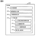
- the noise removing unit 270 includes a repeat operation unit 275 for executing a repeat operation, and a plurality of restricting units (271 to 273) for setting constraint conditions in the repeat operation.
- the measurement control unit 210 operates the sequence control device 114 according to a pulse sequence set based on parameters input by the user via the input device 115, and measures nuclear magnetic resonance signals (echo signals) under predetermined conditions. Do.
- the pulse sequence used by the measurement control unit 210 is not particularly limited, but here, the case of imaging at a thinning rate of 1/2 (double rate 2) using a 2D-GrE system pulse sequence will be described.
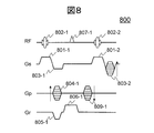
- FIG. 8 shows an example of a 2D-RSSG (RF-spoiled-Steady-state Acquisition with Rewound Gradient-Echo) sequence 800 as an example of a pulse sequence of the 2D-GrE system.
- RF, Gs, Gp, and Gr respectively represent a high frequency magnetic field, a slice gradient magnetic field, a phase encoding gradient magnetic field, and a readout gradient magnetic field.
- a radio frequency magnetic field (RF) pulse 802 is irradiated with the application of the slice gradient magnetic field pulse 801 to excite the magnetization of a predetermined slice in the subject 101.
- RF radio frequency magnetic field
- a phase encoding gradient magnetic field pulse 804 for adding positional information in the phase encoding direction is applied together with the application of a rephase slice gradient magnetic field pulse 803 for converging the phase of magnetization dispersed with the application of the slice type difference magnetic field pulse 801. Apply.
- nuclear magnetic resonance signal (while applying readout gradient magnetic field pulse 806 for adding positional information in the readout direction) Echo 807 is measured.
- a phase encoding gradient magnetic field pulse 809 for rephase for focusing the phase of the nuclear magnetization dephased by the phase encoding gradient magnetic field pulse 804 is applied.
- the measurement control unit 210 repeatedly executes the above procedure at the repetition time TR while changing the intensity of the phase encoding gradient magnetic field pulses 804 and 809 (the number kp of phase encodings) and the phase of the RF pulse 802 Measure the echo required to obtain an image of At this time, in order to perform measurement at double speed in the phase encode direction, the measurement is performed while skipping the phase encode number kp determined by the FOV by skipping one. Thereby, the imaging time can be reduced to half. Also, for each repetition, the phase of the RF pulse 802 is increased by, for example, 117 degrees. In FIG. 8, the numbers below the hyphen indicate the number of repetitions.
- the complex image generation unit 240 arranges the echo signals measured by the plurality of receiving coils in S 701 in k space as k space data, and performs inverse Fourier transform on the k space data to obtain a complex image. calculate.
- the complex image obtained at this time has both sides 901 and 902 of the phase encoding direction of the object 900 (indicated by hatching) on the opposite side (right side on the left side, left side on the other side). To the right), resulting in a spatially overlapping image 910.
- the figure shows an image of two receiving coils C1, C2.
- the separated image calculation unit 250 separates spatially overlapped complex images using the sensitivity distributions of the plurality of receiving coils.
- the signal of the image after separation at position n (n is an integer from 1 to N: N is the number of overlapping images, ie, double number in this example) is ⁇ n
- the receiving coil m at position n (m is Assuming that the sensitivity of 1 to M) is C mn
- the signal S m of the image generated from the receiving coil m is expressed by Expression (1).
- vector ⁇ can be calculated from equation (2).
- the matrix C H is a complex transposed matrix of sensitivity matrix C, the matrix [psi, representing respectively the noise correlation matrix between reception coils.
- sensitivity matrix C is a 2 ⁇ 2 matrix
- the vector S is a 2 ⁇ 1 vector.
- Spatially overlapping images 1 1 and ⁇ 2 can be separated by using equation (2). That is, an image 920 as shown in FIG. 9 can be obtained.
- the noise removal unit 270 performs noise removal processing by repetitive operation (repeated processing). In this noise removal processing, the correlation of noise mixed in the images 1 1 and ⁇ 2 separated by the separated image calculation unit 250 is used. The correlation between the noise mixed in the separated images 1 1 and ⁇ 2 can be obtained in advance using, for example, computer simulation, and as shown in FIG. The variance of the sum of 1 1 and ⁇ 2 is smaller than the variance before separation.
- the noise removing unit 270 sets constraints (hereinafter referred to as noise correlation constraints) that the sum image of the separated image before noise removal and the sum image of the separated image after noise removal are substantially equal as the constraint condition of the repetitive operation. Use.
- the noise removing unit 270 add general conditions as noise removing constraints in addition to the noise correlation constraints.
- the restriction condition that the separated image before noise removal and the separated image after noise removal are substantially equal hereinafter referred to as image restriction before and after noise removal
- the noise of the image obtained by mapping the separated image in sparse space It is a constraint equal to zero (hereinafter referred to as sparse space constraint). Therefore, the noise removing unit 270 includes the after-noise removing image limiting unit 271, the noise correlation limiting unit 272, and the sparse space limiting unit 273 that generate each constraint condition.
- FIG. 10 shows a processing flow of noise processing.
- the before and after noise removal image restriction unit 271 generates a function representing the before and after noise removal image restriction (S 1701).
- the noise correlation restriction unit 272 generates a function representing a restriction condition (noise correlation restriction) that the sum image of the separated images before noise removal and the sum image of the separated images after noise removal are substantially equal (S 1702) .
- the sparse space constraint unit 273 generates a function representing the sparse space constraint (S1703).
- the constraints generated in the before and after noise removal image constraint unit 271, the noise correlation constraint unit 272, and the sparse space constraint unit 273 are combined to perform the iterative operation processing (S1704).
- Equation (3) Function E 1 (I 1 , I 2 ) is generated.
- M i represents a weighted image.
- a binary mask is used in which the sensitivity region of the receiving coil is 1 and the other regions are 0.
- Equation (3) The function E 1 (I 1 , I 2 ) of equation (3) is because the separated images I 1 and I 2 after noise removal do not deviate from the images 1 1 and 2 2 before noise removal by excessive noise removal processing Represents a constraint condition of (hereinafter referred to as a front / back image constraint).
- the noise correlation restriction unit 272 generates a function E 2 (I 1 , I 2 ) defined by Expression (4).
- W i represents a weight image.
- a g-factor map is used for the weight image. The g-factor can be determined using the sensitivity distribution of the receiving coil and the correlation matrix of noise between receptions.
- the weight image W i is not limited to this.
- an arbitrary threshold Th may be set, and a weight obtained by subtracting the threshold Th from the g-factor map may be used.
- W i has a smaller value than 0, it is set to 0. Accordingly, restriction of only noise correlation against separation images I 1 and I 2 are overlapped area will act.
- the binary mask M i used in equation (3) may be used as another weight.
- the function E 2 (I 1 , I 2 ) of Equation (4) represents the constraint that the sum of noises before and after noise removal of the separated images I 1 and I 2 is approximately equal, from the correlation of noise after separation. That is, a constraint condition (hereinafter referred to as a noise correlation constraint) for preventing the relationship of the sum of the separated images from being broken by noise removal is indicated.
- a constraint condition hereinafter referred to as a noise correlation constraint
- ⁇ is a sparse space mapping operator that maps an image to a sparse space.
- Wavelet transform is used.
- 1 represents the L1 norm.
- a i represents a weight image.
- g-factor is used for the weight image.
- the A i is not limited thereto, may be used a binary mask M i used in equation (3).
- the function E 3 (I 1 , I 2 ) in equation (5) is a constraint for making an image mapped to a sparse space by Wavelet transform into a more sparse image by L1 norm (hereinafter referred to as a sparse space constraint Represents.
- the iterative operation unit 275 removes noise by iterative operation processing based on the constraints generated by the three constraint units described above. That is, the separated images I 1 and I 2 from which noises are removed by calculating the function E total (I 1 , I 2 ) defined by the equation (6) are respectively calculated.
- ⁇ 1 , ⁇ 2 and ⁇ 3 are regularization parameters, and are parameters for adjusting the weights of the constraints E 1 , E 2 and E 3 respectively.
- a fixed value may be used according to the SNR predicted by the measurement condition.
- a fixed value may be used according to the standard deviation of the noise area of the measured image.
- the separated image after noise removal calculated by the noise removal unit 270 can be displayed on the display 201 (FIG. 1). Alternatively, it may be stored as image data in the external storage device 203 and displayed on a desired display device.
- the noise removal operation is performed with the correlation of the noise of the separated image as the constraint condition. Accuracy can be improved, high quality images can be calculated, and diagnostic accuracy is improved. Further, according to the present embodiment, it is possible to cause deviation from the original image due to noise removal or to be excessively smoothed by repeatedly performing computation using the constraints necessary for noise reduction as well as noise correlation constraints. It can prevent.
- ⁇ Modified Example 1 of First Embodiment> an example in which noise removal processing is performed on an image separated by the SENSE method that performs separation of spatially overlapped signals in the image space has been described, but the present invention is not limited thereto.
- the method SMASH method, GRAPPA method, etc.
- unmeasured data in k space is estimated using coil sensitivity distribution, and an image (separate image) that does not generate spatial aliasing is generated.
- a noise removal process can be applied.
- the image generation unit 230 (FIG. 1) includes a signal separation unit 245 and a complex image generation unit 255.
- a sensitivity distribution information calculation unit 265 is added.
- one k-space data is formed in the signal separation unit 245 using the k-space data of each reception coil and the sensitivity distribution information of each reception coil, and the complex image generation unit 255 generates the k-space data.
- this reconstructed image is an image composed of a plurality of images at spatially different positions (11, 22: separated images in FIG. 9), the above-described processing of the noise removing unit 270 is performed on these separated images. Perform and remove noise.
- the present modification is different from the first embodiment only in the method of generating separated images, and the same effect as the first embodiment can be obtained.
- the sparse space constraint using the Wavelet transform is used, but other sparse space transforms may be used.
- discrete cosine transform or sparse space transform using Total Variation (TV) may be used.
- TV conversion in an arbitrary image I is defined by equation (7).
- the sparse space constraint unit 273 generates equation (7) instead of equation (5).
- ⁇ x , y y , and ⁇ z indicate spatial gradients in the x, y, and z directions, respectively.
- the iterative operation unit 275 performs the iterative operation using the TV of Expression (7) as the function E 3 (I 1 , I 2 ) in Expression (6) to minimize noise.
- the TV is a constraint that the noise of the spatial differential value image of the separated image is substantially equal to zero, and by using the TV, there is an effect that the noise is removed so that the local space is smoothed.
- noise removal is performed on a separated image of images including spatially overlapping signals by thinning and measuring k-space data, but in the present embodiment, a plurality of slices are simultaneously processed.
- SMS imaging to be excited, a separated image of an image in which signals are superimposed from a plurality of slices on one image is targeted.
- the imaging method is different, the method of separating spatially overlapped signals from the image obtained by imaging is the same as the image separation using the plurality of receiving coil sensitivity distributions according to the SENSE method of the first embodiment. It is.
- the drawings used for the description of the first embodiment will be used as appropriate, and the present embodiment will be described focusing on differences from the first embodiment.
- FIG. 12 (a) is a high-speed SE system pulse sequence called TurboSpinEcho or FastSpinEcho etc., in which a reverse RF pulse (180 ° RF pulse) is continuously applied after a 90 ° RF pulse for exciting a predetermined region of the subject.
- a reverse RF pulse 180 ° RF pulse
- a phase encoding gradient magnetic field is applied between adjacent inverted RF pulses and a readout gradient magnetic field is applied to measure an echo signal.
- the RF pulse and the gradient magnetic field pulse applied simultaneously therewith are different from the normal high-speed SE-based pulse sequence for exciting a single slice (a portion surrounded by a square dotted line in FIG. 12A).
- a single slice a portion surrounded by a square dotted line in FIG. 12A.
- an RF pulse (MB: MultiBand pulse (FIG. 12 (b))
- FOG. 12 (b) A slice selective gradient magnetic field of constant strength is applied during the application.
- the RF pulse waveform at time t [sec] RF (t) is expressed as in the following equation (8).
- ⁇ n represents the initial phase when exciting the nth slice.
- the signal of the slice is shifted within the field of view (FOV) by changing the initial phase ⁇ 2 of the RF pulse linearly in the phase encode direction. Let me measure it.
- the SMS pulse sequence is not limited to the one described above.
- the RF pulse is a combination of an RF pulse called a PINS (Power Independent of Number of Slice) pulse as shown in FIG. 12C and a blip-shaped slice gradient magnetic field, or an MB pulse Pulses in combination with PINS pulses are also known, and any pulse may be used.
- PINS Power Independent of Number of Slice
- the echoes generated by such a pulse sequence are measured as the combined signals from the plurality of excited slices.
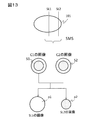
- Image obtained by the k-space data consisting of these echoes Fourier transform for example, as shown in FIG. 13, when the simultaneous excitation of two slices SL1, SL2, images of the image S 1 and the slice SL2 slices SL1 an image S 2 and is superimposed.
- These images S 1 and S 2 obtained by a plurality of receiving coils are images for each slice by solving the equation (2) shown in the first embodiment using sensitivity distributions C 1 and C 2 of the receiving coils, that is, separated images It is possible to obtain ⁇ 1 and ⁇ 2.
- the noise removal unit 270 performs noise removal on the separated image calculated in this way by repeating calculation using a plurality of constraint conditions. That is, as shown in FIG. 10, the noise removing unit 270 performs iterative operation to minimize the function shown in equation (6), with noise removal front / back constraints, noise correlation constraints, and sparse space constraints as constraints to separate them. Remove image noise. As a result, it is possible to obtain a high quality image for each slice from which noise has been removed.
- changes can be made as appropriate, such as applying a modified example (sparse space constraint using TV conversion) as in the modified example 2 of the first embodiment, to the constraint condition of noise removal is there.
- the noise removal of the separated image obtained by separating the spatially overlapped signals is performed by the computer in the MRI apparatus.
- the computer or image processing apparatus independent from the MRI apparatus The practice of the present invention is also encompassed by the present invention.
- the present invention is characterized by utilizing noise correlation between separated images in noise removal of separated images, and in the above embodiment, addition or deletion of elements without departing from the gist is also claimed. Is included in
- 10 MRI apparatus, 100: measuring unit, 101: object, 102: static magnetic field coil, 103: gradient magnetic field coil, 104: shim coil, 105: transmitting coil, 106: receiving coil, 107: transmitter, 108: receiver , 112: power supply unit for gradient magnetic field, 113: power supply unit for shim, 114: sequence control device, 200: computer, 201: display, 203: external storage device, 205: input device, 210: measurement control unit, 230: image Generation unit 240: complex image generation unit 250: separated image calculation unit 270: noise removal unit 271: image restriction unit before and after noise removal 272: noise correlation restriction unit 273: sparse space restriction unit 275: repeated operation Unit, 290: Display control unit
Landscapes
- Physics & Mathematics (AREA)
- Engineering & Computer Science (AREA)
- General Physics & Mathematics (AREA)
- Health & Medical Sciences (AREA)
- High Energy & Nuclear Physics (AREA)
- Nuclear Medicine, Radiotherapy & Molecular Imaging (AREA)
- General Health & Medical Sciences (AREA)
- Radiology & Medical Imaging (AREA)
- Condensed Matter Physics & Semiconductors (AREA)
- Signal Processing (AREA)
- Theoretical Computer Science (AREA)
- Life Sciences & Earth Sciences (AREA)
- Artificial Intelligence (AREA)
- Computer Vision & Pattern Recognition (AREA)
- Animal Behavior & Ethology (AREA)
- Medical Informatics (AREA)
- Molecular Biology (AREA)
- Surgery (AREA)
- Optics & Photonics (AREA)
- Pathology (AREA)
- Public Health (AREA)
- Veterinary Medicine (AREA)
- Biophysics (AREA)
- Spectroscopy & Molecular Physics (AREA)
- Heart & Thoracic Surgery (AREA)
- Biomedical Technology (AREA)
- Magnetic Resonance Imaging Apparatus (AREA)
Priority Applications (1)
| Application Number | Priority Date | Filing Date | Title |
|---|---|---|---|
| US16/639,407 US11393073B2 (en) | 2017-09-07 | 2018-07-27 | Magnetic resonance imaging apparatus and noise elimination method |
Applications Claiming Priority (2)
| Application Number | Priority Date | Filing Date | Title |
|---|---|---|---|
| JP2017172274A JP6762284B2 (ja) | 2017-09-07 | 2017-09-07 | 磁気共鳴イメージング装置およびノイズ除去方法 |
| JP2017-172274 | 2017-09-07 |
Publications (1)
| Publication Number | Publication Date |
|---|---|
| WO2019049549A1 true WO2019049549A1 (ja) | 2019-03-14 |
Family
ID=65634782
Family Applications (1)
| Application Number | Title | Priority Date | Filing Date |
|---|---|---|---|
| PCT/JP2018/028301 Ceased WO2019049549A1 (ja) | 2017-09-07 | 2018-07-27 | 磁気共鳴イメージング装置およびノイズ除去方法 |
Country Status (3)
| Country | Link |
|---|---|
| US (1) | US11393073B2 (enExample) |
| JP (1) | JP6762284B2 (enExample) |
| WO (1) | WO2019049549A1 (enExample) |
Families Citing this family (6)
| Publication number | Priority date | Publication date | Assignee | Title |
|---|---|---|---|---|
| WO2020209566A1 (ko) * | 2019-04-08 | 2020-10-15 | 서울대학교산학협력단 | 인공신경망 기반 핵자기공명 및 자기공명분광 데이터 처리 방법 및 그 장치 |
| JP7407062B2 (ja) * | 2020-04-28 | 2023-12-28 | 富士フイルムヘルスケア株式会社 | 磁気共鳴イメージング装置および画像処理方法 |
| WO2022026644A1 (en) * | 2020-07-31 | 2022-02-03 | Synex Medical Inc. | Weak signal detection system and method |
| JP7557744B2 (ja) * | 2021-06-15 | 2024-09-30 | 富士フイルム株式会社 | 磁気共鳴イメージング装置、ノイズ除去方法、及び画像処理装置 |
| CN114693560B (zh) * | 2022-04-01 | 2025-04-15 | 吴保松 | 一种用于核磁共振成像的降噪方法和降噪系统 |
| CN119779470B (zh) * | 2024-12-25 | 2025-08-12 | 昆明菱恒达科技有限公司 | 一种基于环境监测的多节点边缘感应采样系统及方法 |
Citations (4)
| Publication number | Priority date | Publication date | Assignee | Title |
|---|---|---|---|---|
| JP2002345780A (ja) * | 2001-05-14 | 2002-12-03 | Ge Medical Systems Global Technology Co Llc | マトリクス正則化を用いたmri画像品質改善法 |
| JP2006130285A (ja) * | 2004-10-08 | 2006-05-25 | Hitachi Medical Corp | 磁気共鳴イメージング装置 |
| WO2006109550A1 (ja) * | 2005-03-30 | 2006-10-19 | Hitachi Medical Corporation | 磁気共鳴イメージング装置及び方法 |
| JP2016093494A (ja) * | 2014-11-10 | 2016-05-26 | 株式会社東芝 | 磁気共鳴イメージング装置、画像処理装置及び画像処理方法 |
Family Cites Families (2)
| Publication number | Priority date | Publication date | Assignee | Title |
|---|---|---|---|---|
| US7053613B2 (en) | 2004-06-03 | 2006-05-30 | Fa-Hsuan Lin | Method for parallel image reconstruction using automatic regularization |
| US11300646B2 (en) * | 2014-11-10 | 2022-04-12 | Canon Medical Systems Corporation | Magnetic resonance imaging apparatus, image processing apparatus, and image processing method |
-
2017
- 2017-09-07 JP JP2017172274A patent/JP6762284B2/ja active Active
-
2018
- 2018-07-27 US US16/639,407 patent/US11393073B2/en active Active
- 2018-07-27 WO PCT/JP2018/028301 patent/WO2019049549A1/ja not_active Ceased
Patent Citations (4)
| Publication number | Priority date | Publication date | Assignee | Title |
|---|---|---|---|---|
| JP2002345780A (ja) * | 2001-05-14 | 2002-12-03 | Ge Medical Systems Global Technology Co Llc | マトリクス正則化を用いたmri画像品質改善法 |
| JP2006130285A (ja) * | 2004-10-08 | 2006-05-25 | Hitachi Medical Corp | 磁気共鳴イメージング装置 |
| WO2006109550A1 (ja) * | 2005-03-30 | 2006-10-19 | Hitachi Medical Corporation | 磁気共鳴イメージング装置及び方法 |
| JP2016093494A (ja) * | 2014-11-10 | 2016-05-26 | 株式会社東芝 | 磁気共鳴イメージング装置、画像処理装置及び画像処理方法 |
Non-Patent Citations (1)
| Title |
|---|
| KING, K. F. ET AL.: "Sense image quality improvement using matrix regularization", PROCEEDINGS OF INTERNATIONAL SOCIETY FOR MAGNETIC RESONANCE IN MEDICINE, 21 April 2001 (2001-04-21), XP002296230 * |
Also Published As
| Publication number | Publication date |
|---|---|
| JP6762284B2 (ja) | 2020-09-30 |
| JP2019042444A (ja) | 2019-03-22 |
| US11393073B2 (en) | 2022-07-19 |
| US20200258199A1 (en) | 2020-08-13 |
Similar Documents
| Publication | Publication Date | Title |
|---|---|---|
| US8427156B2 (en) | Systems and methods for image reconstruction of sensitivity encoded MRI data | |
| US9396562B2 (en) | MRI reconstruction with incoherent sampling and redundant haar wavelets | |
| US9915717B2 (en) | Method for rapid whole brain magnetic resonance imaging with contrast preparation | |
| US7019523B2 (en) | Nuclear magnetic resonance imaging apparatus and nuclear magnetic resonance imaging method | |
| JP6762284B2 (ja) | 磁気共鳴イメージング装置およびノイズ除去方法 | |
| US9317917B2 (en) | Method, reconstruction device, and magnetic resonance apparatus for reconstructing magnetic resonance raw data | |
| CN105051563B (zh) | 使用相位调制rf脉冲的并行多切片mr成像 | |
| JP5127841B2 (ja) | 磁気共鳴イメージング装置及び磁化率強調画像撮影方法 | |
| CN103027681B (zh) | 用于重构并行获取的mri图像的系统 | |
| CN107072586A (zh) | 磁共振成像装置 | |
| CN102654568A (zh) | 用来确定对于磁共振成像的激励参数的方法和装置 | |
| CN102654569A (zh) | 用于处理复数图像数据的方法和装置 | |
| US9841481B2 (en) | Multislice acquisition with incoherent aliasing | |
| US11965945B2 (en) | Magnetic resonance system and shimming method and imaging method thereof | |
| US9846216B2 (en) | Magnetic resonance imaging apparatus and magnetic resonance imaging method | |
| US11918335B2 (en) | Magnetic resonance imaging method, apparatus, and computer storage medium | |
| US11080825B2 (en) | Magnetic resonance imaging apparatus and image processing method | |
| CN115389992A (zh) | 磁共振拍摄装置以及灵敏度分布算出程序 | |
| US11105878B2 (en) | Systems and methods for image artifact reduction in simultaneous multi-slice magnetic resonance imaging | |
| JP7645739B2 (ja) | 磁気共鳴イメージング装置およびその制御方法 | |
| US10823803B2 (en) | Method and apparatus for reconstructing contrast levels from magnetic resonance acquisitions | |
| Xiang | Advanced Image Reconstruction and Sampling Pattern Optimization in Silent MRI | |
| WO2021247857A1 (en) | System and methods for ultra-fast multi-dimensional diffusion-relaxation mri using time-division multiplexing sequences | |
| Kılıç | Rapid Multi-Contrast Magnetic Resonance Imaging and Time-of-Flight Angiography | |
| Takizawa et al. | Parallel imaging of head with a dedicated multi-coil on a 0.4 T open MRI |
Legal Events
| Date | Code | Title | Description |
|---|---|---|---|
| 121 | Ep: the epo has been informed by wipo that ep was designated in this application |
Ref document number: 18854633 Country of ref document: EP Kind code of ref document: A1 |
|
| NENP | Non-entry into the national phase |
Ref country code: DE |
|
| 122 | Ep: pct application non-entry in european phase |
Ref document number: 18854633 Country of ref document: EP Kind code of ref document: A1 |