US11393073B2 - Magnetic resonance imaging apparatus and noise elimination method - Google Patents
Magnetic resonance imaging apparatus and noise elimination method Download PDFInfo
- Publication number
- US11393073B2 US11393073B2 US16/639,407 US201816639407A US11393073B2 US 11393073 B2 US11393073 B2 US 11393073B2 US 201816639407 A US201816639407 A US 201816639407A US 11393073 B2 US11393073 B2 US 11393073B2
- Authority
- US
- United States
- Prior art keywords
- noise
- image
- separated images
- magnetic resonance
- constraint
- Prior art date
- Legal status (The legal status is an assumption and is not a legal conclusion. Google has not performed a legal analysis and makes no representation as to the accuracy of the status listed.)
- Active, expires
Links
Images


Classifications
-
- G—PHYSICS
- G06—COMPUTING OR CALCULATING; COUNTING
- G06T—IMAGE DATA PROCESSING OR GENERATION, IN GENERAL
- G06T5/00—Image enhancement or restoration
- G06T5/70—Denoising; Smoothing
-
- G06T5/002—
-
- A—HUMAN NECESSITIES
- A61—MEDICAL OR VETERINARY SCIENCE; HYGIENE
- A61B—DIAGNOSIS; SURGERY; IDENTIFICATION
- A61B5/00—Measuring for diagnostic purposes; Identification of persons
- A61B5/05—Detecting, measuring or recording for diagnosis by means of electric currents or magnetic fields; Measuring using microwaves or radio waves
- A61B5/055—Detecting, measuring or recording for diagnosis by means of electric currents or magnetic fields; Measuring using microwaves or radio waves involving electronic [EMR] or nuclear [NMR] magnetic resonance, e.g. magnetic resonance imaging
-
- G—PHYSICS
- G01—MEASURING; TESTING
- G01R—MEASURING ELECTRIC VARIABLES; MEASURING MAGNETIC VARIABLES
- G01R33/00—Arrangements or instruments for measuring magnetic variables
- G01R33/20—Arrangements or instruments for measuring magnetic variables involving magnetic resonance
- G01R33/44—Arrangements or instruments for measuring magnetic variables involving magnetic resonance using nuclear magnetic resonance [NMR]
- G01R33/48—NMR imaging systems
- G01R33/483—NMR imaging systems with selection of signals or spectra from particular regions of the volume, e.g. in vivo spectroscopy
- G01R33/4833—NMR imaging systems with selection of signals or spectra from particular regions of the volume, e.g. in vivo spectroscopy using spatially selective excitation of the volume of interest, e.g. selecting non-orthogonal or inclined slices
- G01R33/4835—NMR imaging systems with selection of signals or spectra from particular regions of the volume, e.g. in vivo spectroscopy using spatially selective excitation of the volume of interest, e.g. selecting non-orthogonal or inclined slices of multiple slices
-
- G—PHYSICS
- G01—MEASURING; TESTING
- G01R—MEASURING ELECTRIC VARIABLES; MEASURING MAGNETIC VARIABLES
- G01R33/00—Arrangements or instruments for measuring magnetic variables
- G01R33/20—Arrangements or instruments for measuring magnetic variables involving magnetic resonance
- G01R33/44—Arrangements or instruments for measuring magnetic variables involving magnetic resonance using nuclear magnetic resonance [NMR]
- G01R33/48—NMR imaging systems
- G01R33/54—Signal processing systems, e.g. using pulse sequences ; Generation or control of pulse sequences; Operator console
- G01R33/56—Image enhancement or correction, e.g. subtraction or averaging techniques, e.g. improvement of signal-to-noise ratio and resolution
- G01R33/5608—Data processing and visualization specially adapted for MR, e.g. for feature analysis and pattern recognition on the basis of measured MR data, segmentation of measured MR data, edge contour detection on the basis of measured MR data, for enhancing measured MR data in terms of signal-to-noise ratio by means of noise filtering or apodization, for enhancing measured MR data in terms of resolution by means for deblurring, windowing, zero filling, or generation of gray-scaled images, colour-coded images or images displaying vectors instead of pixels
-
- G—PHYSICS
- G01—MEASURING; TESTING
- G01R—MEASURING ELECTRIC VARIABLES; MEASURING MAGNETIC VARIABLES
- G01R33/00—Arrangements or instruments for measuring magnetic variables
- G01R33/20—Arrangements or instruments for measuring magnetic variables involving magnetic resonance
- G01R33/44—Arrangements or instruments for measuring magnetic variables involving magnetic resonance using nuclear magnetic resonance [NMR]
- G01R33/48—NMR imaging systems
- G01R33/54—Signal processing systems, e.g. using pulse sequences ; Generation or control of pulse sequences; Operator console
- G01R33/56—Image enhancement or correction, e.g. subtraction or averaging techniques, e.g. improvement of signal-to-noise ratio and resolution
- G01R33/561—Image enhancement or correction, e.g. subtraction or averaging techniques, e.g. improvement of signal-to-noise ratio and resolution by reduction of the scanning time, i.e. fast acquiring systems, e.g. using echo-planar pulse sequences
- G01R33/5611—Parallel magnetic resonance imaging, e.g. sensitivity encoding [SENSE], simultaneous acquisition of spatial harmonics [SMASH], unaliasing by Fourier encoding of the overlaps using the temporal dimension [UNFOLD], k-t-broad-use linear acquisition speed-up technique [k-t-BLAST], k-t-SENSE
-
- G—PHYSICS
- G01—MEASURING; TESTING
- G01R—MEASURING ELECTRIC VARIABLES; MEASURING MAGNETIC VARIABLES
- G01R33/00—Arrangements or instruments for measuring magnetic variables
- G01R33/20—Arrangements or instruments for measuring magnetic variables involving magnetic resonance
- G01R33/44—Arrangements or instruments for measuring magnetic variables involving magnetic resonance using nuclear magnetic resonance [NMR]
- G01R33/48—NMR imaging systems
- G01R33/54—Signal processing systems, e.g. using pulse sequences ; Generation or control of pulse sequences; Operator console
- G01R33/56—Image enhancement or correction, e.g. subtraction or averaging techniques, e.g. improvement of signal-to-noise ratio and resolution
- G01R33/565—Correction of image distortions, e.g. due to magnetic field inhomogeneities
- G01R33/56545—Correction of image distortions, e.g. due to magnetic field inhomogeneities caused by finite or discrete sampling, e.g. Gibbs ringing, truncation artefacts, phase aliasing artefacts
-
- G—PHYSICS
- G06—COMPUTING OR CALCULATING; COUNTING
- G06T—IMAGE DATA PROCESSING OR GENERATION, IN GENERAL
- G06T5/00—Image enhancement or restoration
- G06T5/50—Image enhancement or restoration using two or more images, e.g. averaging or subtraction
-
- G—PHYSICS
- G01—MEASURING; TESTING
- G01R—MEASURING ELECTRIC VARIABLES; MEASURING MAGNETIC VARIABLES
- G01R33/00—Arrangements or instruments for measuring magnetic variables
- G01R33/20—Arrangements or instruments for measuring magnetic variables involving magnetic resonance
- G01R33/44—Arrangements or instruments for measuring magnetic variables involving magnetic resonance using nuclear magnetic resonance [NMR]
- G01R33/48—NMR imaging systems
- G01R33/54—Signal processing systems, e.g. using pulse sequences ; Generation or control of pulse sequences; Operator console
- G01R33/546—Interface between the MR system and the user, e.g. for controlling the operation of the MR system or for the design of pulse sequences
-
- G—PHYSICS
- G06—COMPUTING OR CALCULATING; COUNTING
- G06T—IMAGE DATA PROCESSING OR GENERATION, IN GENERAL
- G06T2207/00—Indexing scheme for image analysis or image enhancement
- G06T2207/10—Image acquisition modality
- G06T2207/10072—Tomographic images
- G06T2207/10088—Magnetic resonance imaging [MRI]
-
- G—PHYSICS
- G06—COMPUTING OR CALCULATING; COUNTING
- G06T—IMAGE DATA PROCESSING OR GENERATION, IN GENERAL
- G06T2207/00—Indexing scheme for image analysis or image enhancement
- G06T2207/20—Special algorithmic details
- G06T2207/20024—Filtering details
- G06T2207/20028—Bilateral filtering
-
- G—PHYSICS
- G06—COMPUTING OR CALCULATING; COUNTING
- G06T—IMAGE DATA PROCESSING OR GENERATION, IN GENERAL
- G06T2207/00—Indexing scheme for image analysis or image enhancement
- G06T2207/20—Special algorithmic details
- G06T2207/20024—Filtering details
- G06T2207/20032—Median filtering
Definitions
- the present invention relates to a magnetic resonance imaging (MRI) technique. More particularly, it relates to an image processing technique for eliminating noise from an image where spatially overlapping signals are separated, in images acquired by a plurality of receiver coils.
- MRI magnetic resonance imaging
- a magnetic resonance imaging (MRI) apparatus is non-invasive medical image diagnostic equipment utilizing a nuclear magnetic resonance phenomenon where hydrogen nuclei (protons) placed in a static magnetic field are resonated with an RF magnetic field at a specific frequency.
- the MRI is capable of taking images of various tissue contrast with changes of an imaging method or imaging parameters, and this allows acquisition of, not only morphological information but also information relating to a living body such as bloodstream and metabolic functions.
- the MRI is indispensable for a field of diagnostic imaging.
- Methods for shortening imaging-time in the MRI includes high-speed scanning of k-space such as Echo Planar Imaging (EPI) and Fast Spin Echo (FSE), and measuring a few points in k-space to reconstruct unmeasured points by signal processing, such as SENSE method (e.g., Non Patent Literature 1) and GRAPPA method (e.g., Non Patent Literature 2).
- SENSE method e.g., Non Patent Literature 1
- GRAPPA method e.g., Non Patent Literature 2D multi-slice measurement
- CAIPIRINHA method e.g., Non Patent Literature 3
- a plurality of receiver coils acquire spatially overlapping signals, and the spatially overlapping signals are separated by using a difference in sensitivity distribution between the receiver coils.
- a signal-to-noise ratio (SNR) of the image after the separation (separated image) made up of signals separated by the PI method is known to be inversely proportional to an index referred to as Geometry factor (g-factor).
- Geometry factor g-factor
- noise elimination method using regularization e.g., Non Patent Literature 4
- noise elimination method combining a reference image and regularization e.g., Patent Literature 1.
- Non Patent Literature 4 prior information referred to as Zeroth Order Regularization combined with a process for separating the sensitivity by using a difference in sensitivity distribution between the receiver coils, is applied to spatially overlapping signals, whereby separated images with reduced noise can be obtained.
- the method of Non Patent Literature 4 has a problem that an effect of noise reduction is low, because the prior information included in the regularization does not represent characteristics between the spatially overlapping signals.
- Patent Literature 1 prior information referred to as Tikhonov regularization, reference images not overlapping spatially, and a process for separating the sensitivity by using a difference in sensitivity distribution between the receiver coils, are combined and applied to spatially overlapping signals, whereby separated images with reduced noise can be obtained.
- the method described in Patent Literature 1 requires measurement of the reference images not overlapping spatially in advance, in addition to the reception sensitivity distribution, and thus, the imaging time tends to be extended.
- the present invention has been made in view of the situations as described above, and an objective of the present invention is to provide a technique for eliminating noise of the separated images obtained by separating spatially overlapping signals according to the PI method, in the images acquired by a plurality of the receiver coils, without the necessity for an additional reference image.
- sensitivity distributions of a plurality of receiver coils are used to calculate a plurality of separated images obtained by separating spatially overlapping signals, from nuclear magnetic resonance signals received by the plurality of receiver coils. Then, noise is eliminated on the basis of a correlation of noise mixed between the separated images.
- the spatially overlapping signals represent signals (superimposed signals) that are overlapping one another in the state each of the signals from different positions cannot be identified by the signal itself.
- the spatially superimposed signals described in the present specification includes not only superimposed signals in the image space, but also signals in k-space that become the spatially superimposed signals when an image is reconstructed.
- an MRI apparatus comprises, a measuring part that includes a transmission part configured to transmit an RF (Radio Frequency) pulse to a subject placed in a static magnetic field, a reception part configured to receive nuclear magnetic resonance signals generated from the subject by a plurality of receiver coils, and a gradient magnetic field generator configured to provide a gradient magnetic field to the static magnetic field, and a computer configured to perform computations on the nuclear magnetic resonance signals thus received, wherein the computer comprises an image generator configured to process the nuclear magnetic resonance signals received by the plurality of receiver coils to generate a plurality of separated images not spatially overlapping one another, by using sensitivity information of the plurality of receiver coils, and a noise eliminator configured to eliminate noise from each of the separated images, on the basis of a correlation of noise mixed between the separated images.
- RF Radio Frequency
- a high quality noise-eliminated image can be computed, without imaging references images or a similar image for eliminating noise. This prevents extension of total imaging time, and diagnostic precision can be improved.
- FIG. 1 is a block diagram shown a schematic configuration of an MRI apparatus according to an embodiment of the present invention
- FIGS. 2A to 2C are external views of the MM apparatus to which the present invention is applied;
- FIG. 2A illustrates an MRI apparatus of vertical magnetic field type
- FIG. 2B illustrates an MRI apparatus of horizontal magnetic field type
- FIG. 2C illustrates an MRI apparatus enhancing the sense of openness;
- FIG. 3 is a flowchart showing one embodiment of a processing according to a computer
- FIGS. 4A and 4B illustrate noise correlations
- FIG. 4A illustrates the noise correlation of a real part of a complex image
- FIG. 4B illustrates the noise correlation of an imaginary part of the complex image
- FIG. 5 illustrates one example of UI for selecting a noise elimination method
- FIG. 6 is a functional block diagram of the computer according to a first embodiment
- FIG. 7 is a flowchart showing a processing of the computer according to the first embodiment
- FIG. 8 shows one example of a pulse sequence employed in the first embodiment
- FIG. 9 illustrates one example of spatially overlapping signals according to the first embodiment
- FIG. 10 is a flowchart showing a processing of a noise eliminator according to the first embodiment
- FIG. 11 is a functional block diagram of the computer according to a second embodiment
- FIG. 12A illustrates one example of the pulse sequence employed in a second embodiment
- FIGS. 12B and 12C illustrate essential portions thereof
- FIG. 13 illustrates one example of the spatially overlapping signals according to the second embodiment.
- the MRI apparatus comprises broadly, a measuring part 100 configured to measure nuclear magnetic resonance signals generated from a subject 101 , and a computer 200 configured to control the measuring part 100 , and to perform image reconstruction, correction, and other computations by using the nuclear magnetic resonance signals measured by the measuring part 100 .
- the measuring part 100 is provided with a static magnetic field coil 102 configured to generate a static magnetic field in the space where the subject 101 is placed, a transmission part ( 105 , 107 ) configured to transmit an RF pulse to the subject 101 placed within the static magnetic field, a reception part ( 106 , 108 ) configured to receive nuclear magnetic resonance signals generated from the subject, and a gradient coil 103 configured to provide magnetic gradient to the static magnetic field generated from the static magnetic field coil 102 , in order to give positional information to the nuclear magnetic resonance signals.
- a static magnetic field coil 102 configured to generate a static magnetic field in the space where the subject 101 is placed
- a transmission part 105 , 107
- a reception part 106 , 108
- a gradient coil 103 configured to provide magnetic gradient to the static magnetic field generated from the static magnetic field coil 102 , in order to give positional information to the nuclear magnetic resonance signals.
- the static magnetic field coil 102 comprises a normal conductive-type or superconductive-type static magnetic field coil, a magnet for generating static magnetic field, and others, and the direction of generated static magnetic field determines a mode, a vertical magnetic field mode or a horizontal magnetic field mode, and depending on the mode, the shape of the coil and an external view of the entire apparatus are different.
- FIGS. 2( a ) to 2( c ) illustrate external views of various types of the MRI apparatus different in the mode. The present embodiment is applicable to any of the illustrated types of the MRI apparatus.
- the transmission part is provided with a transmit RF coil 105 (hereinafter, simply referred to as “transmit coil”) configured to transmit an RF magnetic field to a measurement area of the subject 101 , and a transmitter 107 provided with an RF oscillator, an amplifier, and others.
- the reception part is provided with a receiver 108 including a receive RF coil 106 (hereinafter, simply referred to as “receiver coil”) configured to receive nuclear magnetic resonance signals generated from the subject 101 , a quadrature detector, an A/D converter, and others.
- the receiver coil comprises a plurality of channels (small receiver coils), and the quadrature detector and the A/D converter incorporated in the receiver 108 are connected to each of the channels.
- the nuclear magnetic resonance signals received by the receiver 108 are passed to the computer 200 , in the form of complex digital signals.
- spatially overlapping signals are measured and those signals are separated in a reconstructed image.
- sensitivity distributions of the receiver coils are used, which receive the magnetic resonance signals generated from the subject 101 .
- the number of the receiver coils 106 is at least equal to or more than the number of signals being separated.
- the gradient coil 103 includes three gradient coils to apply gradient magnetic fields to x-direction, y-direction, and z-direction, respectively, and each of the gradient coils is connected to the power supply for the gradient magnetic field 112 . Furthermore, the MRI apparatus may be provided with a shim coil 104 for adjusting a static magnetic field distribution, and a shim power supply 113 for driving the shim coil.
- the measuring part 100 is further provided with a sequence controller 114 configured to control operations of the measuring part 100 .
- the sequence controller 114 controls the operations of the power supply for the gradient magnetic field 112 , the transmitter 107 and the receiver 108 , and further controls the timing for applying the gradient magnetic field and the RF magnetic field and for receiving the nuclear magnetic resonance signals.
- the time chart for the control is referred to as a pulse sequence, and it is preset in response to the measurement and stored in a storage unit and the others, provided in the computer 200 described below.
- the computer 200 controls the entire operations of the MRI apparatus 100 , and performs various computing operations on the received nuclear magnetic resonance signals.
- the computer 200 is an information processor provided with a CPU, a memory, the storage unit, and others.
- the computer 200 is connected to a display 201 , an external storage unit 203 , an input unit 205 , and so on.
- the display 201 is an interface to present results for an operator, the results being obtained by the computing process.
- the input unit 205 is an interface prompting the operator to enter conditions, parameters, and others, necessary for the measurement and the computing process performed in the present embodiment.
- the user is allowed to enter measurement parameters, for example, such as the number of times speed in a PI (Parallel Imaging) method, via the input unit 205 .
- the external storage unit 203 together with the storage unit within the computer 200 , holds data used in various computations executed by the computer 200 , data obtained by the computations, inputted conditions and parameters, and others.
- the computer 200 generates sensitivity distributions of the receiver coils, separated images, a noise eliminated image, and others. Therefore, as shown in FIG. 1 , the computer 200 is provided with functional parts, such as a measurement controller 210 , an image generator 230 , a noise eliminator 270 , and a display controller 290 . Functions of those parts are implementable in the form of software incorporated in the computer 200 , and they are implemented when the CPU loads the programs (software) held in the storage unit and executes the programs. Various data used in the processing of each function, and various data generated during the processing, are stored in the storage unit or in the external storage unit 203 .
- another information processor independent of the MRI apparatus 10 may implement at least one of the various functions implemented by the computer 200 . All or apart of the functions may be implemented by hardware such as ASIC (Application Specific Integrated Circuit) and FPGA (field-programmable gate array).
- ASIC Application Specific Integrated Circuit
- FPGA field-programmable gate array
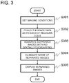
- FIG. 3 shows the details of the processing.
- settings such as an imaging sequence and imaging conditions, configured by a user are accepted via the input unit 115 (S 301 ).
- the imaging sequence is not limited, but in the present embodiment, in order to reduce the imaging time, an imaging method (PI method) for measuring spatially overlapping signals is selected and settings for this method are configured.
- the imaging conditions include parameters of the imaging sequence (repetition time TR and echo time TE), and a thinning rate (reduction factor) is included if the thinning measurement (under-sampling) in k-space is performed.
- SMS Simultaneous Multi-Slice
- settings of the number of slices are also included.
- the spatially overlapping signals indicate signals coming from different positions in real space, overlapping one another without encoded by the gradient magnetic field. These signals may include signals spatially overlapping after under-sampling is performed (signals containing so-called aliasing), and signals from the simultaneous multi-slice (SMS). The measurement method determines what type is the “spatially overlapping signal”.
- the measurement controller 210 allows the sequence controller 114 to operate according to the pulse sequence configured on the basis of the parameters entered by the user, and measures nuclear magnetic resonance signals (echo signals) under a predetermined condition.
- the sequence controller 114 controls each part of the MRI apparatus 100 according to an instruction from the measurement controller 210 , and measures the spatially overlapping signals so as to reduce the imaging time (S 302 ). That is, k-space data is collected with respect to each receiver coil.
- the image generator 230 separates the spatially overlapping signals to form a plurality of images (separated images) at spatially different positions, by using the k-space data as to each of the receiver coils and sensitivity distributions of a plurality of receiver coils (S 303 ).
- the noise eliminator 270 removes noise on the basis of a correlation of noise included in each of the separated images (S 304 ). Noise elimination is implemented by performing an iterative operation for minimizing noise under predetermined constraints, similar to the publicly known non-linear filters such as TotalVariation regularization and sparse regularization.
- the noise eliminator 270 of the present embodiment performs the iterative operation that includes as a constraint, the noise correlation between separated images.
- FIG. 4 shows a specific example of the noise correlations obtained by the simulation.
- the sensitivity distributions of 15-channel receiver coils were used, being calculated by measuring a human head part, and complex noise images corresponding to 15 channels, uncorrelated with one another, were created. These complex noise images were combined, modeled into two complex images overlapping each other, and two separated images were obtained by using the sensitivity distributions of the 15-channel receiver coils.
- FIGS. 4( a ) and 4( b ) show results of plotting signals, respectively, of the real part and the imaginary part of the separated two images ⁇ 1 and ⁇ 2 , where the horizontal axis represents ⁇ 1 and the vertical axis represents ⁇ 2 .
- the noise elimination method of the present embodiment is made selectable, in addition to the publicly known noise elimination methods, for example, a linear filter such as a median filter and Gaussian filter, an edge preserving filter such as Bilateral filter, and a non-linear filter such as TotalVariation regularization and sparse regularization.
- a linear filter such as a median filter and Gaussian filter
- an edge preserving filter such as Bilateral filter
- a non-linear filter such as TotalVariation regularization and sparse regularization. This configuration enhances flexibility in user's method selection.
- the separated images after noise is eliminated are stored in the storage unit 203 as required, or presented on the display 201 (S 305 ).
- multiple receiver coils are used to acquire spatially overlapping signals. Then, those signals are separated into a plurality of images (separated images) not overlapping spatially, by using the sensitivity distribution of each of the receiver coils, and noise in the separated images is removed by using the noise correlation between the separated images as the constraints.
- noise correlation between the separated images as constraints for the noise elimination process, allows highly accurate noise elimination, specialized in eliminating noise in the separated images.
- FIG. 1 The overview of the MRI apparatus as shown in FIG. 1 is common to all the embodiments and referred to as required.
- a 2D parallel imaging method that performs under-sampling in the phase encoding direction is employed. Further in the present embodiment, spatially overlapping signals are separated according to the SENSE method. In other words, the k-space data collected as to each of the receiver coils is subjected to image reconstruction, and then, separated images are generated by computations from thus obtained images.
- FIG. 6 shows a configuration of the computer 200 according to the present embodiment.
- the image generator 230 includes a complex image generator 240 and a separated image calculator 250 .
- the noise eliminator 270 is provided with an iterative operation part 275 for executing the iterative operation, and a plurality of constraint parts ( 271 to 273 ) for setting the constraints in the iterative operation.
- the measurement controller 210 activates the sequence controller 114 according to the pulse sequence configured on the basis of the parameters entered by a user via an input unit 115 . Then, nuclear magnetic resonance signals (echo signals) under predetermined conditions are measured.
- the pulse sequence used by the measurement controller 210 is not particularly limited. However, in this example, there will be described the case where a 2D-GrE type pulse sequence is used to perform imaging at a thinning rate 1/2 (reduction factor is 2).
- FIG. 8 shows a 2D-RSSG (RF-spoiled-Steady-state Acquisition with Rewound Gradient-Echo) sequence 800 as an example of the 2D-GrE type pulse sequence.
- RF, Gs, Gp, and Gr represent, respectively, an RF magnetic field, a slice gradient magnetic field, a phase encoding gradient magnetic field, and a readout gradient magnetic field.
- an RF magnetic field (RF) pulse 802 is applied with application of a slice gradient pulse 801 , thereby exciting magnetization of a given slice within the subject 101 .
- RF RF magnetic field
- a phase encoding gradient pulse 804 is applied for adding positional information in the phase encoding direction.
- a nuclear magnetic resonance signal (echo) 807 is measured while applying the readout gradient pulse 806 for adding the positional information in the readout direction.
- a phase encoding gradient pulse for rephasing 809 is applied for convergence of magnetizing phase that has been dephased by the phase encoding gradient pulse 804 .
- the measurement controller 210 repeatedly executes the procedures above every repetition time TR, while varying the strength of the phase encoding gradient pulses 804 and 809 (the number of phase encoding kp) and the phase of the RF pulse 802 , whereby echoes necessary for obtaining one image are measured.
- the measurement is performed with the number of the phase encoding kp determined by an FOV, taking every other phase encoding number. Accordingly, the imaging time can be reduced to half.
- the phase of the RF pulse 802 is incremented by 117 degrees every repetition, for instance. In FIG. 8 , the number following the hyphen indicates the number of repetitions.
- the complex image generator 240 places in k-space, each of the echo signals measured by a plurality of receiver coils in S 701 , and k-space data is obtained. Then, this k-space data is subjected to the Fourier transform, whereby a complex image is calculated.
- FIG. 9 for example, in the complex image thus obtained, each of the areas on the both sides (diagonally shaded areas) 901 and 902 in the phase encoding direction of the subject 900 is folded on the other side (the right-side area is folded on the left side, and the left-side area is folded on the right side), and spatially overlapping image 910 is obtained.
- images of two receiver coils C 1 and C 2 are shown.
- the separated image calculator 250 separates the spatially overlapping complex image, by using sensitivity distributions of the plurality of receiver coils.
- Signals S m of the images generated from the receive coils m are given by the following equation (1) where a signal of the separated image at the position n (n is an integer from 1 to N:N is the number of image overlapping, i.e., the reduction factor, which is “2 (double)” in this example) is ⁇ n , and the sensitivity of the receive coil m (m is an integer from 1 to M) at the position n is C mn :
- the matrix C H represents the complex conjugate transpose of a matrix of the sensitivity matrix C
- the matrix ⁇ represents noise correlation matrix between the receiver coils.
- the vector ⁇ is 2 ⁇ 1 vector
- the sensitivity matrix C is 2 ⁇ 2 matrix
- the vector S is 2 ⁇ 1 vector.
- Equation (2) the spatially overlapping images ⁇ 1 and ⁇ 2 can be separated. That is, the image 920 as shown in FIG. 9 can be obtained.
- the noise eliminator 270 performs the noise elimination process according to an iterative operation (repetitive process).
- the noise elimination process uses a correlation of noise mixed into the images ⁇ 1 and ⁇ 2 separated by the separated image calculator 250 .
- the correlation of the noise mixed into the separated images ⁇ 1 and ⁇ 2 can be obtained in advance according to the computer simulation, for instance.
- the noise correlation is negative, and variance of the sum of the images ⁇ 1 and ⁇ 2 after the separation is smaller than the variance before the separation.
- the noise eliminator 270 uses a constraint (hereinafter, referred to as “noise correlation constraint”), as a constraint of the iterative operation, indicating that a sum image of the separated images before noise elimination is nearly equal to a sum image of the separated images after noise elimination.
- noise correlation constraint a constraint of the iterative operation
- the general conditions may be added to the noise eliminator 270 , in addition to the noise correlation constraint.
- the general conditions may include a constraint that the separated images before noise elimination are nearly equal to the images after noise elimination (hereinafter, referred to as “constraint for image before and after noise elimination), and a constraint indicating that noise of the image obtained by mapping the separated image in sparse space is nearly equal to zero (hereinafter, referred to as “sparse space constraint”).
- the noise eliminator 270 is provided with a constraint part for image before and after noise elimination 271 , a noise correlation constraint part 272 , and a sparse space constraint part 273 , and these constraint parts are configured to generate the constraints, respectively.
- FIG. 10 is a flowchart of the noise processing.
- the constraint part for image before and after noise elimination 271 generates a function representing the constraint for image before and after noise elimination (S 1701 ).
- the noise correlation constraint part 272 generates a function representing the constraint (noise correlation constraint) that the sum image of the separated images before noise elimination is nearly equal to the sum image of separated images after noise elimination (S 1702 ).
- the sparse constraint part 273 generates a function representing the sparse space constraint (S 1703 ).
- the constraint part for image before and after noise elimination 271 , the noise correlation constraint part 272 , and the sparse space constraint part 273 are combined to perform the processing of the iterative operation (S 1704 ).
- the constraint part for image before and after noise elimination 271 generates the function E 1 (I 1 , I 2 ) defined by Equation (3) where the separated images before noise elimination are ⁇ 1 and ⁇ 2 , and the separated images after noise elimination are I 1 and I 2 :
- Equation (3) represents the constraint (hereinafter, referred to as “before and after image constraint”) indicating that the separated images I 1 and I 2 after the noise elimination do not move away from the images ⁇ 1 and ⁇ 2 before noise elimination, due to excessive noise elimination process.
- the noise correlation constraint part 272 generates a function E 2 (I 1 , I 2 ) defined by Equation (4):
- a g-factor map is used as the weighted image, for instance.
- the g-factor can be obtained by using the sensitivity distributions of the receiver coils and the noise correlation matrix between receptions.
- the weighted image W i is not limited to the aforementioned one.
- a freely selected threshold Th is provided to use a weight obtained by subtracting the threshold Th from the g-factor map.
- W i is smaller than zero, it is set to zero.
- the binary mask M i employed in Equation (3) may also be used.
- Function E 2 (I 1 , I 2 ) of Equation (4) represents the constraint indicating that a sum of noise in the separated images I 1 and I 2 before noise elimination is nearly equal to the sum of noise in the separated images I 1 and I 2 after noise elimination, according to the noise correlation after the separation. In other words, this function indicates that the noise elimination does not affect the summing relation of the separated images after the separation (hereinafter, referred to as “noise correlation constraint”).
- the sparse constraint part 273 generates the function E 3 (I 1 , I 2 ) defined by Equation (5).
- Wavelet transform is used, for instance.
- ⁇ 1 represents L1 norm.
- the weighted image is represented by A i .
- the g-factor is used as the weighted image.
- the weighted image A i is not limited to those as described above, and the binary mask M i used in Equation (3) may be employed.
- Function E 3 (I 1 , I 2 ) of Equation (5) represents the constraint (hereinafter, referred to as “sparse space constraint”) that is provided to make the image mapped in the sparse space according to Wavelet transform be a sparser image according to L1 norm.
- the iterative operation part 275 eliminates noise according to the iterative operation based on the constraints generated by the aforementioned three constraint parts as described above. In other words, Function E total (I 1 , I 2 ) given by Equation (6) is minimized, thereby calculating the separated images I 1 and I 2 from which noise has been eliminated.
- E total ⁇ ( I 1 , I 2 ) arg ⁇ ⁇ min I 1 , I 2 ⁇ ⁇ ⁇ 1 ⁇ E 1 ⁇ ( I 1 , I 2 ) + ⁇ 2 ⁇ E 2 ⁇ ( I 1 , I 2 ) + ⁇ 3 ⁇ E 3 ⁇ ( I 1 , I 2 ) ⁇ ( 6 )
- ⁇ 1 , ⁇ 2 , and ⁇ 3 are regularization parameters respectively adjusting the weights of the constraints E 1 , E 2 , and E 3 .
- a fixed value may be used in response to an SNR that is estimated by measurement conditions.
- a fixed value may be used in response to a standard deviation in the noise area of the measured images.
- the separated images after noise is eliminated, calculated by the noise eliminator 270 can be presented on the display 201 ( FIG. 1 ).
- the external storage unit 203 stores the separated images as image data, and they may be displayed on a desired displaying unit.
- the MRI apparatus and the image processing method of the present embodiment computations for noise elimination are performed in the images acquired by using a plurality of receiver coils, using the noise correlation in the separated images as the constraints, and thereby enhancing the precision of noise elimination in the separated images and obtaining a high-quality image, then achieving improved accuracy in diagnosis.
- the iterative operation is performed by using the constraints necessary for noise reduction, together with the noise correlation constraint, thereby preventing displacements of image from an original image and excessive smoothing, due to the noise elimination.
- the noise elimination process is performed on the images separated according to the SENSE method for separating the spatially overlapping signals in the image space.
- the noise elimination process as described in the first embodiment may also be applicable to other methods (such as SMASH method and GRAPPA method) where unmeasured data in k-space is estimated, by using the coil sensitivity distribution, to generate images (separated images) with no spatial aliasing.
- the image generator 230 ( FIG. 1 ) comprises a signal separator 245 and a complex image generator 255 .
- a sensitivity distribution information calculator 265 is added.
- the signal separator 245 uses the k-space data of each receiver coil and the sensitivity distribution information of each receiver coil to form one k-space data
- the complex image generator 255 reconstructs an image by using thus formed k-space data.
- This reconstructed image comprises a plurality of images ( ⁇ 1 , ⁇ 2 : separated images in FIG. 9 ) at spatially different positions, and thus the processing of the aforementioned noise eliminator 270 is performed on these separated images, so as to eliminate noise.
- the present modification is different from the first embodiment in how to generate the separated images, and the same effect as the first embodiment can be obtained.
- the sparse space constraint using the Wavelet transform is employed in the noise elimination process, in addition to the noise correlation constraint.
- Another type of sparse space transform can be used.
- the sparse space transform using the discrete cosine transform or Total Variation (TV) may be used.
- Equation (7) defines the TV transform of any image I.
- the sparse constraint part 273 generates Equation (7) instead of Equation (5).
- the iterative operation part 275 performs the iterative operation by using TV in Equation (7) as the function E 3 (I 1 , I 2 ) in Equation (6), thereby minimizing noise.
- TV is a constraint indicating that noise in a spatial differential value image of the separated images is nearly zero, and using TV produces an effect of noise elimination that achieves local spatial smoothing.
- noise elimination is performed on the separated images of an image including spatially overlapping signals, by thinning measurement (reduction measurement) of k-space data.
- thinning measurement reduction measurement
- the imaging method is different from the first embodiment, but the method for separating spatially overlapping signals from an image obtained by imaging, is the same as the image separation using a plurality of receiver coils according to the SENSE method of the first embodiment.
- the present embodiment will now be described, focusing on a point different from the first embodiment.
- FIG. 12( a ) shows one example of the SMS pulse sequence employed in the present embodiment.
- FIG. 12( a ) illustrates a fast spin-echo pulse sequence, called as TurboSpinEcho, FastSpinEcho, and others.
- RF pulses 180° RF pulses
- RF pulses are sequentially applied after application of 90° RF pulse for exciting a certain region on a subject.
- a readout gradient magnetic field is applied together with applying a phase-encoding gradient magnetic field, between adjacent inversion RF pulses, and an echo signal is measured. Varying the amount of the phase-encoding gradient magnetic field being applied for every echo, allows collection of data that fills the k-space in one or more times of excitation.
- the RF pulse and the gradient magnetic field pulse applied simultaneously with the RF pulse are different from those in a normal fast spin-echo pulse sequence that excites a single slice (portions surrounded by the dotted boxes in FIG. 12( a ) ).
- an RF pulse (MB: MultiBand pulse ( FIG. 12( b ) ) is used, being the RF pulse where transmission frequencies are mixed, respectively associated with the positions of a plurality of slices simultaneously excited.
- a slice-selective gradient magnetic field with constant strength is applied.
- an RF pulse waveform RF(t) at the time t[sec] is expressed by the following equation (8):
- N 2
- the SMS pulse sequence is not limited to the pulse sequence as described above.
- the RF pulse may be not only an MB pulse, but also a combination of a pulse called as PINS (Power Independent of Number of Slice) pulse as shown in FIG. 12( c ) , and a blip-like slice gradient magnetic field, or a pulse such as a combination of the MB pulse and PINS pulse. Any of these pulses may be used.
- PINS Power Independent of Number of Slice
- an echo generated by such pulse sequence as described above is measured, assuming that signals from a plurality of excited slices are combined.
- an image obtained by applying Fourier transform to the k-space data comprising those echoes is an image where the image S 1 of the slice SL 1 and the image S 2 of the slice SL 2 are overlapping, when two slices SL 1 and SL 2 are excited simultaneously. From these images S 1 and S 2 obtained by the plurality of receiver coils, and by solving Equation (2) with the use of the sensitivity distributions C 1 and C 2 of the receiver coils, according to the first embodiment, images slice by slice, i.e., separated images ⁇ 1 and ⁇ 2 can be obtained.
- the noise eliminator 270 performs the noise elimination by the iterative operation using a plurality of constraints, on thus calculated separated images.
- the iterative operation for minimizing the function as expressed by Equation (6) is performed, under the constraints including the constraint before and after noise elimination, the noise correlation constraint, and the sparse space constraints, thereby removing the noise in the separated images. Accordingly, it is possible to obtain a high quality image as to each slice from which noise has been eliminated.
- the present embodiment can also be modified as appropriate, for example, applying the modification such as the modification 2 of the first embodiment (sparse space constraint using TV transform), to the constraint for noise elimination.
- the noise elimination from the separated images obtained by separating spatially overlapping signals is executed in the computer incorporated in the MRI apparatus.
- the present invention includes that the noise elimination is executed in a computer or in an image processor, independent from the MRI apparatus.
- the scope of the present invention is to use the noises correlation between the separated images in eliminating noise from the separated images, and in the aforementioned embodiments, the present invention also includes addition or deletion of any elements, without departing from the scope of the invention.
Landscapes
- Physics & Mathematics (AREA)
- Engineering & Computer Science (AREA)
- General Physics & Mathematics (AREA)
- Health & Medical Sciences (AREA)
- High Energy & Nuclear Physics (AREA)
- Nuclear Medicine, Radiotherapy & Molecular Imaging (AREA)
- General Health & Medical Sciences (AREA)
- Radiology & Medical Imaging (AREA)
- Condensed Matter Physics & Semiconductors (AREA)
- Signal Processing (AREA)
- Theoretical Computer Science (AREA)
- Life Sciences & Earth Sciences (AREA)
- Artificial Intelligence (AREA)
- Computer Vision & Pattern Recognition (AREA)
- Animal Behavior & Ethology (AREA)
- Medical Informatics (AREA)
- Molecular Biology (AREA)
- Surgery (AREA)
- Optics & Photonics (AREA)
- Pathology (AREA)
- Public Health (AREA)
- Veterinary Medicine (AREA)
- Biophysics (AREA)
- Spectroscopy & Molecular Physics (AREA)
- Heart & Thoracic Surgery (AREA)
- Biomedical Technology (AREA)
- Magnetic Resonance Imaging Apparatus (AREA)
Applications Claiming Priority (4)
| Application Number | Priority Date | Filing Date | Title |
|---|---|---|---|
| JP2017172274A JP6762284B2 (ja) | 2017-09-07 | 2017-09-07 | 磁気共鳴イメージング装置およびノイズ除去方法 |
| JP2017-172274 | 2017-09-07 | ||
| JPJP2017-172274 | 2017-09-07 | ||
| PCT/JP2018/028301 WO2019049549A1 (ja) | 2017-09-07 | 2018-07-27 | 磁気共鳴イメージング装置およびノイズ除去方法 |
Publications (2)
| Publication Number | Publication Date |
|---|---|
| US20200258199A1 US20200258199A1 (en) | 2020-08-13 |
| US11393073B2 true US11393073B2 (en) | 2022-07-19 |
Family
ID=65634782
Family Applications (1)
| Application Number | Title | Priority Date | Filing Date |
|---|---|---|---|
| US16/639,407 Active 2039-03-10 US11393073B2 (en) | 2017-09-07 | 2018-07-27 | Magnetic resonance imaging apparatus and noise elimination method |
Country Status (3)
| Country | Link |
|---|---|
| US (1) | US11393073B2 (enExample) |
| JP (1) | JP6762284B2 (enExample) |
| WO (1) | WO2019049549A1 (enExample) |
Families Citing this family (6)
| Publication number | Priority date | Publication date | Assignee | Title |
|---|---|---|---|---|
| WO2020209566A1 (ko) * | 2019-04-08 | 2020-10-15 | 서울대학교산학협력단 | 인공신경망 기반 핵자기공명 및 자기공명분광 데이터 처리 방법 및 그 장치 |
| JP7407062B2 (ja) * | 2020-04-28 | 2023-12-28 | 富士フイルムヘルスケア株式会社 | 磁気共鳴イメージング装置および画像処理方法 |
| WO2022026644A1 (en) * | 2020-07-31 | 2022-02-03 | Synex Medical Inc. | Weak signal detection system and method |
| JP7557744B2 (ja) * | 2021-06-15 | 2024-09-30 | 富士フイルム株式会社 | 磁気共鳴イメージング装置、ノイズ除去方法、及び画像処理装置 |
| CN114693560B (zh) * | 2022-04-01 | 2025-04-15 | 吴保松 | 一种用于核磁共振成像的降噪方法和降噪系统 |
| CN119779470B (zh) * | 2024-12-25 | 2025-08-12 | 昆明菱恒达科技有限公司 | 一种基于环境监测的多节点边缘感应采样系统及方法 |
Citations (6)
| Publication number | Priority date | Publication date | Assignee | Title |
|---|---|---|---|---|
| US20020167316A1 (en) | 2001-05-14 | 2002-11-14 | King Kevin F. | MRI image quality improvement using matrix regularization |
| US20050270024A1 (en) | 2004-06-03 | 2005-12-08 | Fa-Hsuan Lin | Method for parallel image reconstruction using automatic regularization |
| JP2006130285A (ja) | 2004-10-08 | 2006-05-25 | Hitachi Medical Corp | 磁気共鳴イメージング装置 |
| WO2006109550A1 (ja) | 2005-03-30 | 2006-10-19 | Hitachi Medical Corporation | 磁気共鳴イメージング装置及び方法 |
| US20160131730A1 (en) * | 2014-11-10 | 2016-05-12 | Kabushiki Kaisha Toshiba | Magnetic resonance imaging apparatus, image processing apparatus, and image processing method |
| JP2016093494A (ja) | 2014-11-10 | 2016-05-26 | 株式会社東芝 | 磁気共鳴イメージング装置、画像処理装置及び画像処理方法 |
-
2017
- 2017-09-07 JP JP2017172274A patent/JP6762284B2/ja active Active
-
2018
- 2018-07-27 US US16/639,407 patent/US11393073B2/en active Active
- 2018-07-27 WO PCT/JP2018/028301 patent/WO2019049549A1/ja not_active Ceased
Patent Citations (9)
| Publication number | Priority date | Publication date | Assignee | Title |
|---|---|---|---|---|
| US20020167316A1 (en) | 2001-05-14 | 2002-11-14 | King Kevin F. | MRI image quality improvement using matrix regularization |
| JP2002345780A (ja) | 2001-05-14 | 2002-12-03 | Ge Medical Systems Global Technology Co Llc | マトリクス正則化を用いたmri画像品質改善法 |
| US20050270024A1 (en) | 2004-06-03 | 2005-12-08 | Fa-Hsuan Lin | Method for parallel image reconstruction using automatic regularization |
| US7053613B2 (en) | 2004-06-03 | 2006-05-30 | Fa-Hsuan Lin | Method for parallel image reconstruction using automatic regularization |
| JP2006130285A (ja) | 2004-10-08 | 2006-05-25 | Hitachi Medical Corp | 磁気共鳴イメージング装置 |
| WO2006109550A1 (ja) | 2005-03-30 | 2006-10-19 | Hitachi Medical Corporation | 磁気共鳴イメージング装置及び方法 |
| US20090206835A1 (en) | 2005-03-30 | 2009-08-20 | Norimasa Nakai | Magnetic Resonance Imaging Apparatus and Method |
| US20160131730A1 (en) * | 2014-11-10 | 2016-05-12 | Kabushiki Kaisha Toshiba | Magnetic resonance imaging apparatus, image processing apparatus, and image processing method |
| JP2016093494A (ja) | 2014-11-10 | 2016-05-26 | 株式会社東芝 | 磁気共鳴イメージング装置、画像処理装置及び画像処理方法 |
Non-Patent Citations (7)
| Title |
|---|
| Breuer et al., "Controlled Aliasing in Parallel Imaging Results in Higher Acceleration (CAIPIRINHA) for Multi-Slice Imaging", Magnetic Resonance in Medicine, 2005, pp. 684-691, vol. 53, Wiley-Liss, Inc. (eight (8) pages). |
| Griswold M et al., "Generalized Autocalibrating Partially Parallel Acquisitions (GRAPPA)", Magnetic Resonance in Medicine, 2002, pp. 1202-1210, vol. 47, Wiley-Liss, Inc. (nine (9) pages). |
| International Preliminary Report on Patentability (PCT/IB/373) issued in PCT Application No. PCT/JP2018/028301 dated Mar. 10, 2020, Including English translation of document C2 (Japanese-language Written Opinion (PCT/ISA/237), filed on Feb. 14, 2020) (five (5) pages). |
| International Search Report (PCT/ISA/210) issued in PCT Application No. PCT/JP2018/028301 dated Oct. 30, 2018 with English translation (four (4) pages). |
| Japanese-language Written Opinion (PCT/ISA/237) issued in PCT Application No. PCT/JP2018/028301 dated Oct. 30, 2018 (three (3) pages). |
| King K. et al., "SENSE Image Quality Improvement Using Matrix Regularization", In Proceedings of the 9th Annual Meeting of ISMRM, Glasgow, Scotland, 2001, p. 1771 (one (1) page). |
| Pruessmann K. et al., "SENSE: Sensitivity Encoding for Fast MRI", Magnetic Resonance in Medicine, 1999, pp. 952-962, vol. 42, Wiley-Liss, Inc. (11 pages). |
Also Published As
| Publication number | Publication date |
|---|---|
| JP6762284B2 (ja) | 2020-09-30 |
| JP2019042444A (ja) | 2019-03-22 |
| WO2019049549A1 (ja) | 2019-03-14 |
| US20200258199A1 (en) | 2020-08-13 |
Similar Documents
| Publication | Publication Date | Title |
|---|---|---|
| US11393073B2 (en) | Magnetic resonance imaging apparatus and noise elimination method | |
| US9778336B2 (en) | System and method for rapid, multi-shot segmented magnetic resonance imaging | |
| US10605881B2 (en) | Magnetic resonance imaging apparatus and image processing method | |
| US10338176B2 (en) | Method and apparatus for actuation of a magnetic resonance scanner for the simultaneous acquisition of multiple slices | |
| US8934691B2 (en) | System for motion compensated MR parallel imaging | |
| US20130088225A1 (en) | System for Reconstructing MRI Images Acquired in Parallel | |
| US10088543B2 (en) | Parallel multi-slice MR imaging using phase-modulated RF pulses | |
| US11047935B2 (en) | Systems and methods for estimating complex B1+ fields of transmit coils of a magnetic resonance imaging (MRI) system | |
| US10859652B2 (en) | MR imaging with dixon-type water/fat separation | |
| US9971007B2 (en) | Method and apparatus for accelerated magnetic resonance imaging | |
| US20220057467A1 (en) | Epi mr imaging with distortion correction | |
| US11965945B2 (en) | Magnetic resonance system and shimming method and imaging method thereof | |
| US9753108B2 (en) | Magnetic resonance imaging method for at least two separate radio-frequency transmit coils with time-delayed slice-selective excitation pulses | |
| US10955506B2 (en) | Parallel MR imaging with spectral fat suppression | |
| US20160018500A1 (en) | Magnetic resonance imaging apparatus and magnetic resonance imaging method | |
| US12029544B2 (en) | Method for the reduction of interference signals | |
| EP3966583B1 (en) | Dual echo steady state mr imaging using bipolar diffusion gradients | |
| JP6487554B2 (ja) | 磁気共鳴イメージング装置 | |
| US11467238B2 (en) | Method for uniform reconstruction of multi-channel surface-coil magnetic resonance data without use of a reference scan | |
| WO2018001759A1 (en) | Diffusion weighted mr imaging using multi-shot epi with motion detection and modified sense reconstruction | |
| JP3688795B2 (ja) | 磁気共鳴イメージング装置 | |
| US11051695B2 (en) | Magnetic resonance imaging apparatus | |
| JP7645739B2 (ja) | 磁気共鳴イメージング装置およびその制御方法 | |
| US10823803B2 (en) | Method and apparatus for reconstructing contrast levels from magnetic resonance acquisitions | |
| Claeser | Fast mapping of the T1-relaxation in magnetic resonance imaging with advanced spiral k-space sampling and interleaving methods at 3 Tesla and 7 Tesla |
Legal Events
| Date | Code | Title | Description |
|---|---|---|---|
| FEPP | Fee payment procedure |
Free format text: ENTITY STATUS SET TO UNDISCOUNTED (ORIGINAL EVENT CODE: BIG.); ENTITY STATUS OF PATENT OWNER: LARGE ENTITY |
|
| STPP | Information on status: patent application and granting procedure in general |
Free format text: DOCKETED NEW CASE - READY FOR EXAMINATION |
|
| STPP | Information on status: patent application and granting procedure in general |
Free format text: NON FINAL ACTION MAILED |
|
| AS | Assignment |
Owner name: FUJIFILM HEALTHCARE CORPORATION, JAPAN Free format text: ASSIGNMENT OF ASSIGNORS INTEREST;ASSIGNOR:HITACHI, LTD.;REEL/FRAME:058425/0886 Effective date: 20211203 |
|
| STPP | Information on status: patent application and granting procedure in general |
Free format text: RESPONSE TO NON-FINAL OFFICE ACTION ENTERED AND FORWARDED TO EXAMINER |
|
| STPP | Information on status: patent application and granting procedure in general |
Free format text: NOTICE OF ALLOWANCE MAILED -- APPLICATION RECEIVED IN OFFICE OF PUBLICATIONS |
|
| STPP | Information on status: patent application and granting procedure in general |
Free format text: PUBLICATIONS -- ISSUE FEE PAYMENT VERIFIED |
|
| STCF | Information on status: patent grant |
Free format text: PATENTED CASE |
|
| AS | Assignment |
Owner name: FUJIFILM CORPORATION, JAPAN Free format text: MERGER;ASSIGNOR:FUJIFILM HEALTHCARE CORPORATION;REEL/FRAME:070607/0754 Effective date: 20240701 |
|
| AS | Assignment |
Owner name: FUJIFILM CORPORATION, JAPAN Free format text: MERGER;ASSIGNOR:FUJIFILM HEALTHCARE CORPORATION;REEL/FRAME:069869/0968 Effective date: 20240701 |