WO2019049331A1 - Dispositif d'étalonnage, système d'étalonnage, et procédé d'étalonnage - Google Patents
Dispositif d'étalonnage, système d'étalonnage, et procédé d'étalonnage Download PDFInfo
- Publication number
- WO2019049331A1 WO2019049331A1 PCT/JP2017/032563 JP2017032563W WO2019049331A1 WO 2019049331 A1 WO2019049331 A1 WO 2019049331A1 JP 2017032563 W JP2017032563 W JP 2017032563W WO 2019049331 A1 WO2019049331 A1 WO 2019049331A1
- Authority
- WO
- WIPO (PCT)
- Prior art keywords
- image
- imaging device
- chart
- correction
- calibration
- Prior art date
Links
- 238000000034 method Methods 0.000 title claims abstract description 82
- 238000012937 correction Methods 0.000 claims abstract description 195
- 238000003384 imaging method Methods 0.000 claims abstract description 132
- 239000003550 marker Substances 0.000 claims abstract description 23
- 230000003287 optical effect Effects 0.000 claims description 13
- 238000004590 computer program Methods 0.000 claims description 3
- 238000005070 sampling Methods 0.000 claims description 3
- 238000011156 evaluation Methods 0.000 claims description 2
- 238000003491 array Methods 0.000 claims 1
- 238000012545 processing Methods 0.000 description 53
- 230000008569 process Effects 0.000 description 44
- 230000036544 posture Effects 0.000 description 23
- 230000009466 transformation Effects 0.000 description 11
- 230000010365 information processing Effects 0.000 description 10
- 230000015654 memory Effects 0.000 description 9
- 238000010586 diagram Methods 0.000 description 8
- 230000006870 function Effects 0.000 description 5
- 238000006243 chemical reaction Methods 0.000 description 4
- 230000033001 locomotion Effects 0.000 description 4
- 230000007613 environmental effect Effects 0.000 description 3
- 238000010191 image analysis Methods 0.000 description 3
- 230000008901 benefit Effects 0.000 description 2
- 238000004364 calculation method Methods 0.000 description 2
- 230000008859 change Effects 0.000 description 2
- 238000004891 communication Methods 0.000 description 2
- 230000000694 effects Effects 0.000 description 2
- 238000005516 engineering process Methods 0.000 description 2
- 230000008570 general process Effects 0.000 description 2
- 239000011159 matrix material Substances 0.000 description 2
- 238000012986 modification Methods 0.000 description 2
- 230000004048 modification Effects 0.000 description 2
- 238000012544 monitoring process Methods 0.000 description 2
- 230000009467 reduction Effects 0.000 description 2
- 239000004065 semiconductor Substances 0.000 description 2
- 230000007704 transition Effects 0.000 description 2
- 238000013459 approach Methods 0.000 description 1
- 230000003190 augmentative effect Effects 0.000 description 1
- 238000005452 bending Methods 0.000 description 1
- 230000000295 complement effect Effects 0.000 description 1
- 230000007423 decrease Effects 0.000 description 1
- 230000001419 dependent effect Effects 0.000 description 1
- 230000002431 foraging effect Effects 0.000 description 1
- 230000004807 localization Effects 0.000 description 1
- 238000013507 mapping Methods 0.000 description 1
- 230000007246 mechanism Effects 0.000 description 1
- 229910044991 metal oxide Inorganic materials 0.000 description 1
- 150000004706 metal oxides Chemical class 0.000 description 1
- 230000002093 peripheral effect Effects 0.000 description 1
- 230000002265 prevention Effects 0.000 description 1
- 238000009877 rendering Methods 0.000 description 1
- 238000011160 research Methods 0.000 description 1
- 230000008054 signal transmission Effects 0.000 description 1
- 230000001131 transforming effect Effects 0.000 description 1
- 230000000007 visual effect Effects 0.000 description 1
Images


Classifications
-
- H—ELECTRICITY
- H04—ELECTRIC COMMUNICATION TECHNIQUE
- H04N—PICTORIAL COMMUNICATION, e.g. TELEVISION
- H04N17/00—Diagnosis, testing or measuring for television systems or their details
- H04N17/002—Diagnosis, testing or measuring for television systems or their details for television cameras
-
- G—PHYSICS
- G06—COMPUTING; CALCULATING OR COUNTING
- G06T—IMAGE DATA PROCESSING OR GENERATION, IN GENERAL
- G06T15/00—3D [Three Dimensional] image rendering
- G06T15/10—Geometric effects
- G06T15/20—Perspective computation
-
- G06T5/80—
-
- G—PHYSICS
- G06—COMPUTING; CALCULATING OR COUNTING
- G06T—IMAGE DATA PROCESSING OR GENERATION, IN GENERAL
- G06T7/00—Image analysis
- G06T7/70—Determining position or orientation of objects or cameras
-
- G—PHYSICS
- G06—COMPUTING; CALCULATING OR COUNTING
- G06T—IMAGE DATA PROCESSING OR GENERATION, IN GENERAL
- G06T7/00—Image analysis
- G06T7/80—Analysis of captured images to determine intrinsic or extrinsic camera parameters, i.e. camera calibration
-
- H—ELECTRICITY
- H04—ELECTRIC COMMUNICATION TECHNIQUE
- H04N—PICTORIAL COMMUNICATION, e.g. TELEVISION
- H04N17/00—Diagnosis, testing or measuring for television systems or their details
-
- G—PHYSICS
- G06—COMPUTING; CALCULATING OR COUNTING
- G06T—IMAGE DATA PROCESSING OR GENERATION, IN GENERAL
- G06T2207/00—Indexing scheme for image analysis or image enhancement
- G06T2207/30—Subject of image; Context of image processing
- G06T2207/30204—Marker
- G06T2207/30208—Marker matrix
-
- G—PHYSICS
- G06—COMPUTING; CALCULATING OR COUNTING
- G06T—IMAGE DATA PROCESSING OR GENERATION, IN GENERAL
- G06T2207/00—Indexing scheme for image analysis or image enhancement
- G06T2207/30—Subject of image; Context of image processing
- G06T2207/30244—Camera pose
Definitions
- Patent Document 1 There is known a game in which a user's body or marker is photographed by a camera, and the image area is replaced with another image and displayed on a display (see, for example, Patent Document 1).
- the technology for acquiring the position and movement of the subject and the camera itself and recognizing the attributes of the subject by detecting and analyzing the image in the photographed image is not only the camera mounted on the game device and the information terminal but also the crime prevention It is widely introduced in systems including cameras, on-board cameras, cameras with robots, etc.
- the external parameters define the relationship between the camera coordinate system and the world coordinate system, and are used especially for the purpose of adjusting the inclination of the images captured by performing calibration simultaneously for multi-view cameras such as stereo cameras.
- a calibration technique a plane chart of a checkered pattern is photographed from a plurality of viewpoints, and the position of the feature point on the photographed image and the position of the feature point on the plane of the chart in real space have a correct correspondence relationship Zhang's method for optimizing parameters is widely known (see Non-Patent Document 1).
- the calibration device 10 stores the obtained parameters in an internal memory or outputs the parameters to an external device (not shown).
- the information processing such as the above-described electronic game may be performed using the obtained parameter, and the function may be displayed on an output device (not shown). It is also conceivable to create a surrounding environment map by mounting on a robot together with the imaging device 12 and analyzing the captured image using the parameters. In these cases, an information processing apparatus having the function of the calibration apparatus 10 can be realized.
- the size of the image is a function of the ratio of the focal distance fa to the distance Za, if the ratio is the same, the size of the image may be the same even if the distance Za is different. In other words, the position of the viewpoint and the angle of view can not be determined simultaneously from the size of the image on one captured image. Therefore, in calibration of a general imaging device, various camera parameters are obtained by capturing a chart from various directions to obtain a simultaneous equation or capturing a fixed distance to the chart.
- the CPU 122 controls the entire apparatus by executing the operating system stored in the storage unit 134.
- the CPU 122 also executes various programs read from the removable storage medium and loaded into the main memory 126 or downloaded via the communication unit 132.
- the GPU 124 has a geometry engine function and a rendering processor function, and performs image drawing in accordance with a drawing command from the CPU 122.
- the above-mentioned correction for lens distortion is eliminated Performs an inverse correction to produce a distorted image similar to the captured image.
- this image is referred to as a "pseudo image”.
- the distortion correction unit 34 efficiently generates the corrected image 64 by properly using these processes. Thereafter, the processing path for generating the chart pattern image from the distorted image as in S30 and S32 is “forward direction correction”, and the processing path for generating the distorted image from the chart pattern image as in S34 and S36 It is called “reverse direction correction”.
- the distortion due to the fisheye lens is first corrected in consideration of the difference in projection method, and the correction accuracy is improved by further correcting according to the above equation.
- a corrected image when using the temporary parameters set in S42 is drawn on the image plane prepared in S40 (S44).
- S44 a processing path of reverse direction correction for obtaining a corresponding position coordinate on the photographed image is used.
- an image close to the chart pattern corrected using the temporarily set parameters is generated.
- the left and right ends of the image of the horizontal projection pixel number Nh of the center projection when the angle of view is ⁇ are A and B, and the left and right ends of the image of the corresponding fisheye lens are A2 and B2.
- the point P (i1, j1) on the screen surface 72 of the equidistant projection and the point Q (i2, j2) on the screen surface 70 of the corresponding central projection are the respective image centers (strictly speaking, the positions of the lens centers) And the distances r1 and r2 from C).
- FIG. 12 illustrates the relationship between the screen surface of the expanded central projection and the screen surface of the fisheye lens. This figure is an overhead view of the viewpoint 74 and each screen surface as in FIG. 11. However, by setting the angle of view to 360 °, the screen surface 76 of the fisheye lens becomes an entire spherical surface whose radius is the focal distance f.
- the process in S44 of FIG. 9 is reverse correction in which the position coordinate of the photographed image is obtained from the position coordinate in order to determine the pixel value on the image plane after correction.
- the process of adjusting the setting of the posture so that the grid lines are orthogonal in S48, and the process of adjusting the correction parameter so as to eliminate the distortion in S50 are also performed on the temporarily corrected image by using the reverse correction.
- the degree of adjustment can be evaluated only for specific pixels sampled, and processing efficiency can be increased.
- the projective transformation at S34 of FIG. 8 can be easily realized by means such as using the inverse of the projective transformation matrix described for S32.
- a reverse process of the correction using the distortion correction equation by the correction coefficient is included, and ingenuity is required.
- "a distortion correction unique to a fisheye lens and a correction using a correction coefficient” are performed as a set. Also in the reverse correction, the set is used as it is so as to be substantially reverse correction.
- the approximate angle and position of the lower end of the horizontal line among the grid lines of the chart pattern can be determined.
- a line segment is defined by the angle and the position, and the two line segments formed by dividing the line segment are further moved downward in the image plane to obtain the sum of pixel values through which they pass.
- the line segment enters the black grid line of the chart pattern the sum of pixel values decreases.
- threshold determination Line segments 90a and 90b of the said state are shown in the figure.
- the angle is adjusted depending on which one arrived earlier, and the process of searching for a black grid line again is repeated. As a result, the approximate angle and position of the upper end of the horizontal line among the grid lines of the chart pattern can be determined.
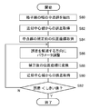
- FIG. 18 is a flowchart showing a processing procedure for the pseudo image drawing unit 42 to draw a pseudo image.
- This process corresponds to S14 of FIG.
- the pseudo image drawing unit 42 first arranges the object model of the chart 200 in a virtual three-dimensional space similar to that shown in FIG. 10, and further obtains the attitude of the imaging device 12 acquired as shown in FIGS. And arrange the virtual camera at the angle of view (S100). For the position, set a temporary value. Then, the image plane of the virtual camera is prepared (S102), and the corresponding position on the chart 200 is determined starting from each pixel in the image plane. This process corresponds to the above-described forward correction.
- a grid line search as described in FIGS. 14 and 15 is also performed on the image, and a marker is detected to obtain the grid line interval and the marker position. Then, the spacing between the grid lines in the corrected image of the photographed image acquired in S52 of FIG. 9 is compared with the position of the marker. If the position of the virtual camera is different from the actual one, those parameters are different from the values obtained for the captured image. Therefore, the viewpoint adjustment unit 44 adjusts the viewpoint position of the virtual camera so as to eliminate the difference. For example, the pseudo image drawing unit 42 draws the pseudo image at the adjusted viewpoint position again and corrects it so that the grid line interval and the marker position are adjusted to match the actual one.
- FIG. 22 exemplifies the photographed image of the chart 200, where (a) shows a chart pattern consisting of a fractal bar code and (b) shows a chart pattern consisting of a lattice and markers on the display screen of the portable terminal. It shows a photographed image when it is displayed on a television receiver. Thus, even when displayed on the screen of the electronic device, the pattern of the chart can be clearly photographed.
- the fractal bar code of (b) calibration is possible even if only a partial area is shown as shown. Therefore, it is possible to easily carry out the calibration by displaying a chart on an electronic device owned by a general user at an arbitrary timing during operation.
- SLAM Simultaneous Localization and Mapping
- three-dimensional information such as the relationship between the position and the posture of the imaging device and the chart can be obtained.
- the angle of view is also three-dimensional information in the sense of defining the field of view for the viewpoint. Therefore, as shown in (b) in operation, since three-dimensional information is given to the photographed image, geometrical information in the three-dimensional space can be acquired. For example, it can be used to create an environmental map as described above. By using the result, it is possible to significantly increase the variation of the information processing. Even when displaying the results, it is possible to accurately represent more attractive image worlds such as virtual reality and augmented reality.
- the correction is repeated while adjusting the parameters until a target image is obtained.
- it is possible to efficiently reach the optimal value of the parameter by focusing on only the sampling point of the evaluation target in the target image and tracking the change due to the adjustment.
- the present embodiment is nothing more than acquiring three-dimensional information from one photographed image using a fisheye lens. Therefore, it can be used for geometric processing in a three-dimensional space, such as creation of an environmental map, also at the time of operation, and variations of processing using a photographed image can be increased.
- the position and orientation of the captured image with respect to the chart are known, it is not necessary to exactly align the chart and the imaging device in calibration.
- a fractal barcode is used as the chart pattern, the position of the imaging device can be specified even when photographing only a partial region, so the degree of freedom for photographing further increases.
- the chart can be displayed on an electronic device, allowing the user to easily carry out calibration regardless of time or place, as a base point for continuous information acquisition thereafter, and latest for aging of the device It can provide a correction environment.
Landscapes
- Engineering & Computer Science (AREA)
- Physics & Mathematics (AREA)
- Theoretical Computer Science (AREA)
- General Physics & Mathematics (AREA)
- Computer Vision & Pattern Recognition (AREA)
- Signal Processing (AREA)
- Multimedia (AREA)
- General Health & Medical Sciences (AREA)
- Biomedical Technology (AREA)
- Health & Medical Sciences (AREA)
- Geometry (AREA)
- Computing Systems (AREA)
- Computer Graphics (AREA)
- Studio Devices (AREA)
- Image Processing (AREA)
- Testing, Inspecting, Measuring Of Stereoscopic Televisions And Televisions (AREA)
- Image Analysis (AREA)
Abstract
L'invention concerne un dispositif d'étalonnage 10 comprenant une unité d'acquisition d'image capturée 30 qui acquiert des données relatives à une image obtenue par imagerie d'un tableau d'étalonnage à l'aide d'un dispositif d'imagerie à très grand angulaire (fish-eye) 12. Une unité de correction de distorsion 34 prend en compte un paramètre du dispositif d'imagerie, exécute une correction selon le procédé de projection, et ajuste le paramètre jusqu'à ce que l'image graphique d'origine soit obtenue. Une unité de dessin d'image simulée 42 dessine de manière simulée une image capturée à l'aide de données de modèle graphique. Une unité d'ajustement de perspective 44 compare l'image simulée et l'image capturée, et identifie la position du dispositif d'imagerie 12 en ajustant la position en perspective d'une caméra virtuelle d'après des différences entre la position d'un marqueur et l'intervalle d'un motif.
Priority Applications (5)
| Application Number | Priority Date | Filing Date | Title |
|---|---|---|---|
| PCT/JP2017/032563 WO2019049331A1 (fr) | 2017-09-08 | 2017-09-08 | Dispositif d'étalonnage, système d'étalonnage, et procédé d'étalonnage |
| CN201880058435.8A CN111095923B (zh) | 2017-09-08 | 2018-05-09 | 校准装置、校准系统和校准方法 |
| JP2019540760A JP6859442B2 (ja) | 2017-09-08 | 2018-05-09 | キャリブレーション装置、キャリブレーションシステム、およびキャリブレーション方法 |
| US16/643,678 US11232593B2 (en) | 2017-09-08 | 2018-05-09 | Calibration apparatus, calibration system, and calibration method |
| PCT/JP2018/018015 WO2019049421A1 (fr) | 2017-09-08 | 2018-05-09 | Dispositif d'étalonnage, système d'étalonnage et procédé d'étalonnage |
Applications Claiming Priority (1)
| Application Number | Priority Date | Filing Date | Title |
|---|---|---|---|
| PCT/JP2017/032563 WO2019049331A1 (fr) | 2017-09-08 | 2017-09-08 | Dispositif d'étalonnage, système d'étalonnage, et procédé d'étalonnage |
Publications (1)
| Publication Number | Publication Date |
|---|---|
| WO2019049331A1 true WO2019049331A1 (fr) | 2019-03-14 |
Family
ID=65634755
Family Applications (2)
| Application Number | Title | Priority Date | Filing Date |
|---|---|---|---|
| PCT/JP2017/032563 WO2019049331A1 (fr) | 2017-09-08 | 2017-09-08 | Dispositif d'étalonnage, système d'étalonnage, et procédé d'étalonnage |
| PCT/JP2018/018015 WO2019049421A1 (fr) | 2017-09-08 | 2018-05-09 | Dispositif d'étalonnage, système d'étalonnage et procédé d'étalonnage |
Family Applications After (1)
| Application Number | Title | Priority Date | Filing Date |
|---|---|---|---|
| PCT/JP2018/018015 WO2019049421A1 (fr) | 2017-09-08 | 2018-05-09 | Dispositif d'étalonnage, système d'étalonnage et procédé d'étalonnage |
Country Status (4)
| Country | Link |
|---|---|
| US (1) | US11232593B2 (fr) |
| JP (1) | JP6859442B2 (fr) |
| CN (1) | CN111095923B (fr) |
| WO (2) | WO2019049331A1 (fr) |
Cited By (3)
| Publication number | Priority date | Publication date | Assignee | Title |
|---|---|---|---|---|
| CN111795805A (zh) * | 2020-06-29 | 2020-10-20 | 歌尔光学科技有限公司 | 测试图的绘制方法、终端设备及存储介质 |
| WO2021079802A1 (fr) * | 2019-10-21 | 2021-04-29 | 株式会社アマダ | Dispositif de traitement d'image photographique de pièce ouvrée, procédé de traitement d'image photographique de pièce ouvrée, et système d'usinage |
| JP2022014921A (ja) * | 2020-12-30 | 2022-01-20 | 阿波羅智聯(北京)科技有限公司 | 路側カメラの外部パラメータに基づく三次元感知情報取得方法及び路側機器 |
Families Citing this family (26)
| Publication number | Priority date | Publication date | Assignee | Title |
|---|---|---|---|---|
| WO2018102990A1 (fr) * | 2016-12-06 | 2018-06-14 | SZ DJI Technology Co., Ltd. | Système et procédé de correction d'une image grand angle |
| CN108596854B (zh) * | 2018-04-28 | 2021-02-12 | 京东方科技集团股份有限公司 | 图像畸变校正方法及装置、计算机可读介质、电子设备 |
| US11210859B1 (en) * | 2018-12-03 | 2021-12-28 | Occam Video Solutions, LLC | Computer system for forensic analysis using motion video |
| CN111435969B (zh) * | 2019-01-11 | 2021-11-09 | 佳能株式会社 | 图像处理装置及其控制方法、记录介质和信息处理系统 |
| CN111667398B (zh) * | 2019-03-07 | 2023-08-01 | 株式会社理光 | 图像处理方法、装置和计算机可读存储介质 |
| JP7192582B2 (ja) * | 2019-03-11 | 2022-12-20 | オムロン株式会社 | 物体追跡装置および物体追跡方法 |
| CN110930336B (zh) * | 2019-11-29 | 2023-11-28 | 深圳市商汤科技有限公司 | 图像处理方法及装置、电子设备和存储介质 |
| DE102020131808A1 (de) * | 2019-12-05 | 2021-06-10 | Denso Wave Incorporated | Vorrichtung zur Unterstützung von Kalibrierungsvorgängen bei Industriekameras |
| CN111210478B (zh) * | 2019-12-31 | 2023-07-21 | 重庆邮电大学 | 一种无共同视野多相机系统外参标定方法、介质及系统 |
| JP2021164095A (ja) * | 2020-04-01 | 2021-10-11 | キヤノン株式会社 | 投影装置 |
| TWI720869B (zh) * | 2020-04-15 | 2021-03-01 | 致伸科技股份有限公司 | 相機模組之對位方法 |
| CN111612720B (zh) * | 2020-05-21 | 2023-11-07 | 烟台艾睿光电科技有限公司 | 一种广角红外图像优化方法、系统及相关组件 |
| JP7474137B2 (ja) | 2020-06-30 | 2024-04-24 | キヤノン株式会社 | 情報処理装置およびその制御方法 |
| JP7449393B2 (ja) | 2020-08-28 | 2024-03-13 | 株式会社デンソーテン | 車載装置および車載カメラのキャリブレーション方法 |
| CN112288649A (zh) * | 2020-10-27 | 2021-01-29 | 长安大学 | 一种圆柱状物体透视成像失真的图像校正方法及设备 |
| CN112468716B (zh) * | 2020-11-02 | 2022-07-19 | 航天信息股份有限公司 | 摄像头视角矫正方法、装置、存储介质及电子设备 |
| KR102661114B1 (ko) * | 2020-11-10 | 2024-04-25 | 삼성전자주식회사 | 카메라 모듈 검사 장치, 카메라 모듈 검사 방법 및 이미지 생성 장치 |
| US11172193B1 (en) * | 2020-12-04 | 2021-11-09 | Argo AI, LLC | Method and system to calibrate camera devices of a vehicle vision system using a programmable calibration target device |
| CN112584136B (zh) * | 2020-12-23 | 2023-02-28 | 上海艾为电子技术股份有限公司 | 位置校准模块、校准方法、电子设备、校准装置及存储介质 |
| CN113538283B (zh) * | 2021-07-22 | 2024-04-30 | 浙江赫千电子科技有限公司 | 一种冗余鱼眼摄像头拍摄图像的畸变矫正方法 |
| CN113687627B (zh) * | 2021-08-18 | 2022-08-19 | 太仓中科信息技术研究院 | 一种基于摄像机器人的目标跟踪方法 |
| CN113822941B (zh) * | 2021-09-03 | 2023-12-19 | 大连中科创达软件有限公司 | 相机倾斜校准方法、装置、设备及存储介质 |
| FR3127063B1 (fr) * | 2021-09-10 | 2023-09-22 | Renault Sas | procédé de génération d’une image finale de l’environnement d’un véhicule automobile |
| CN115100026B (zh) * | 2022-06-15 | 2023-07-14 | 佳都科技集团股份有限公司 | 基于目标对象的标签坐标转换方法、装置、设备及存储介质 |
| CN115314690B (zh) * | 2022-08-09 | 2023-09-26 | 北京淳中科技股份有限公司 | 一种图像融合带处理方法、装置、电子设备及存储介质 |
| CN117392241B (zh) * | 2023-12-11 | 2024-03-05 | 新石器中研(上海)科技有限公司 | 自动驾驶中的传感器标定方法、装置及电子设备 |
Citations (3)
| Publication number | Priority date | Publication date | Assignee | Title |
|---|---|---|---|---|
| WO2007055336A1 (fr) * | 2005-11-11 | 2007-05-18 | Sony Corporation | Dispositif, procede et programme de traitement d'images, support d'enregistrement contenant le programme et dispositif d'imagerie |
| JP2012085026A (ja) * | 2010-10-08 | 2012-04-26 | Toshiba Alpine Automotive Technology Corp | 画像処理装置及び画像処理方法 |
| WO2012120561A1 (fr) * | 2011-03-08 | 2012-09-13 | 三菱電機株式会社 | Appareil de correction d'image de périphérie d'objet en mouvement |
Family Cites Families (12)
| Publication number | Priority date | Publication date | Assignee | Title |
|---|---|---|---|---|
| CN1222911C (zh) | 1998-05-19 | 2005-10-12 | 索尼电脑娱乐公司 | 图像处理装置和方法 |
| JP2003141521A (ja) * | 2001-08-21 | 2003-05-16 | Computer Image Laboratory Co Ltd | 画像表示システム |
| JP4307934B2 (ja) * | 2003-08-13 | 2009-08-05 | 株式会社トプコン | 画像補正機能付撮影装置及び方法、並びに撮影装置及び方法 |
| CN101305596B (zh) * | 2005-11-11 | 2010-06-16 | 索尼株式会社 | 图像处理设备、图像处理方法以及图像拾取设备 |
| JP4757142B2 (ja) * | 2006-08-10 | 2011-08-24 | キヤノン株式会社 | 撮影環境校正方法及び情報処理装置 |
| US9361562B1 (en) * | 2011-10-06 | 2016-06-07 | AI Cure Technologies, Inc. | Method and apparatus for fractal multilayered medication identification, authentication and adherence monitoring |
| JP5898475B2 (ja) | 2011-11-28 | 2016-04-06 | クラリオン株式会社 | 車載カメラシステム及びその較正方法、及びその較正プログラム |
| KR102068992B1 (ko) * | 2013-06-20 | 2020-01-22 | 삼성전자 주식회사 | 렌즈 캘리브레이션 방법 및 영상 복원 방법 |
| WO2016076400A1 (fr) * | 2014-11-13 | 2016-05-19 | オリンパス株式会社 | Dispositif d'étalonnage, procédé d'étalonnage, dispositif optique, dispositif d'imagerie, dispositif de projection, système de mesure, et procédé de mesure |
| US9894350B2 (en) * | 2015-02-24 | 2018-02-13 | Nextvr Inc. | Methods and apparatus related to capturing and/or rendering images |
| CN104809739B (zh) | 2015-05-15 | 2019-03-22 | 南京大学 | 一种超广角镜头相机视频实时校正的方法 |
| CN106815805A (zh) * | 2017-01-17 | 2017-06-09 | 湖南优象科技有限公司 | 基于Bayer图像的快速畸变校正方法 |
-
2017
- 2017-09-08 WO PCT/JP2017/032563 patent/WO2019049331A1/fr active Application Filing
-
2018
- 2018-05-09 CN CN201880058435.8A patent/CN111095923B/zh active Active
- 2018-05-09 US US16/643,678 patent/US11232593B2/en active Active
- 2018-05-09 WO PCT/JP2018/018015 patent/WO2019049421A1/fr active Application Filing
- 2018-05-09 JP JP2019540760A patent/JP6859442B2/ja active Active
Patent Citations (3)
| Publication number | Priority date | Publication date | Assignee | Title |
|---|---|---|---|---|
| WO2007055336A1 (fr) * | 2005-11-11 | 2007-05-18 | Sony Corporation | Dispositif, procede et programme de traitement d'images, support d'enregistrement contenant le programme et dispositif d'imagerie |
| JP2012085026A (ja) * | 2010-10-08 | 2012-04-26 | Toshiba Alpine Automotive Technology Corp | 画像処理装置及び画像処理方法 |
| WO2012120561A1 (fr) * | 2011-03-08 | 2012-09-13 | 三菱電機株式会社 | Appareil de correction d'image de périphérie d'objet en mouvement |
Cited By (8)
| Publication number | Priority date | Publication date | Assignee | Title |
|---|---|---|---|---|
| WO2021079802A1 (fr) * | 2019-10-21 | 2021-04-29 | 株式会社アマダ | Dispositif de traitement d'image photographique de pièce ouvrée, procédé de traitement d'image photographique de pièce ouvrée, et système d'usinage |
| JP2021065950A (ja) * | 2019-10-21 | 2021-04-30 | 株式会社アマダ | ワーク撮影画像処理装置、ワーク撮影画像処理方法、及び加工システム |
| JP7269864B2 (ja) | 2019-10-21 | 2023-05-09 | 株式会社アマダ | ワーク撮影画像処理装置及びワーク撮影画像処理方法 |
| CN111795805A (zh) * | 2020-06-29 | 2020-10-20 | 歌尔光学科技有限公司 | 测试图的绘制方法、终端设备及存储介质 |
| JP2022014921A (ja) * | 2020-12-30 | 2022-01-20 | 阿波羅智聯(北京)科技有限公司 | 路側カメラの外部パラメータに基づく三次元感知情報取得方法及び路側機器 |
| US20220028260A1 (en) * | 2020-12-30 | 2022-01-27 | Apollo Intelligent Connectivity (Beijing) Technology Co., Ltd. | Method for acquiring three-dimensional perception information based on external parameters of roadside camera, and roadside device |
| JP7321231B2 (ja) | 2020-12-30 | 2023-08-04 | 阿波羅智聯(北京)科技有限公司 | 路側カメラの外部パラメータに基づく三次元感知情報取得方法及び路側機器 |
| US11893884B2 (en) | 2020-12-30 | 2024-02-06 | Apollo Intelligent Connectivity (Beijing) Technology Co., Ltd. | Method for acquiring three-dimensional perception information based on external parameters of roadside camera, and roadside device |
Also Published As
| Publication number | Publication date |
|---|---|
| US11232593B2 (en) | 2022-01-25 |
| US20200273205A1 (en) | 2020-08-27 |
| CN111095923B (zh) | 2022-01-04 |
| CN111095923A (zh) | 2020-05-01 |
| JP6859442B2 (ja) | 2021-04-14 |
| WO2019049421A1 (fr) | 2019-03-14 |
| JPWO2019049421A1 (ja) | 2020-07-27 |
Similar Documents
| Publication | Publication Date | Title |
|---|---|---|
| JP6859442B2 (ja) | キャリブレーション装置、キャリブレーションシステム、およびキャリブレーション方法 | |
| US11039121B2 (en) | Calibration apparatus, chart for calibration, chart pattern generation apparatus, and calibration method | |
| KR101761751B1 (ko) | 직접적인 기하학적 모델링이 행해지는 hmd 보정 | |
| TWI555379B (zh) | 一種全景魚眼相機影像校正、合成與景深重建方法與其系統 | |
| JP7218435B2 (ja) | キャリブレーション装置、キャリブレーション用チャート、およびキャリブレーション方法 | |
| JP6201476B2 (ja) | 自由視点画像撮像装置およびその方法 | |
| KR101121034B1 (ko) | 복수의 이미지들로부터 카메라 파라미터를 얻기 위한 시스템과 방법 및 이들의 컴퓨터 프로그램 제품 | |
| CN109003311B (zh) | 一种鱼眼镜头的标定方法 | |
| EP1453001A1 (fr) | Dispositif de traitement d'image, procede de traitement d'image, procede de stockage et programme informatique | |
| TW201715880A (zh) | 一種全景魚眼相機影像校正、合成與景深重建方法與其系統 | |
| CN107809610B (zh) | 摄像头参数集算出装置、摄像头参数集算出方法以及记录介质 | |
| KR102222290B1 (ko) | 혼합현실 환경의 동적인 3차원 현실데이터 구동을 위한 실사기반의 전방위 3d 모델 비디오 시퀀스 획득 방법 | |
| CN110689476A (zh) | 全景图像拼接方法及其装置、可读存储介质和电子设备 | |
| TWI820246B (zh) | 具有像差估計之設備、估計來自廣角影像的像差之方法及電腦程式產品 | |
| JP2003179800A (ja) | 多視点画像生成装置、画像処理装置、および方法、並びにコンピュータ・プログラム | |
| WO2018052100A1 (fr) | Dispositif, procédé et programme de traitement d'images | |
| JP2019525509A (ja) | 水平視差ステレオパノラマ取込方法 | |
| US11216943B2 (en) | Method for producing a two-dimensional whole image | |
| JP2011146762A (ja) | 立体モデル生成装置 | |
| KR102146839B1 (ko) | 실시간 가상현실 구축을 위한 시스템 및 방법 | |
| WO2024063675A1 (fr) | Procédés et systèmes de génération de représentations tridimensionnelles |
Legal Events
| Date | Code | Title | Description |
|---|---|---|---|
| 121 | Ep: the epo has been informed by wipo that ep was designated in this application |
Ref document number: 17924590 Country of ref document: EP Kind code of ref document: A1 |
|
| NENP | Non-entry into the national phase |
Ref country code: DE |
|
| 122 | Ep: pct application non-entry in european phase |
Ref document number: 17924590 Country of ref document: EP Kind code of ref document: A1 |
|
| NENP | Non-entry into the national phase |
Ref country code: JP |