WO2019049331A1 - Calibration device, calibration system, and calibration method - Google Patents
Calibration device, calibration system, and calibration method Download PDFInfo
- Publication number
- WO2019049331A1 WO2019049331A1 PCT/JP2017/032563 JP2017032563W WO2019049331A1 WO 2019049331 A1 WO2019049331 A1 WO 2019049331A1 JP 2017032563 W JP2017032563 W JP 2017032563W WO 2019049331 A1 WO2019049331 A1 WO 2019049331A1
- Authority
- WO
- WIPO (PCT)
- Prior art keywords
- image
- imaging device
- chart
- correction
- calibration
- Prior art date
Links
- 238000000034 method Methods 0.000 title claims abstract description 82
- 238000012937 correction Methods 0.000 claims abstract description 195
- 238000003384 imaging method Methods 0.000 claims abstract description 132
- 239000003550 marker Substances 0.000 claims abstract description 23
- 230000003287 optical effect Effects 0.000 claims description 13
- 238000004590 computer program Methods 0.000 claims description 3
- 238000005070 sampling Methods 0.000 claims description 3
- 238000011156 evaluation Methods 0.000 claims description 2
- 238000003491 array Methods 0.000 claims 1
- 238000012545 processing Methods 0.000 description 53
- 230000008569 process Effects 0.000 description 44
- 230000036544 posture Effects 0.000 description 23
- 230000009466 transformation Effects 0.000 description 11
- 230000010365 information processing Effects 0.000 description 10
- 230000015654 memory Effects 0.000 description 9
- 238000010586 diagram Methods 0.000 description 8
- 230000006870 function Effects 0.000 description 5
- 238000006243 chemical reaction Methods 0.000 description 4
- 230000033001 locomotion Effects 0.000 description 4
- 230000007613 environmental effect Effects 0.000 description 3
- 238000010191 image analysis Methods 0.000 description 3
- 230000008901 benefit Effects 0.000 description 2
- 238000004364 calculation method Methods 0.000 description 2
- 230000008859 change Effects 0.000 description 2
- 238000004891 communication Methods 0.000 description 2
- 230000000694 effects Effects 0.000 description 2
- 238000005516 engineering process Methods 0.000 description 2
- 230000008570 general process Effects 0.000 description 2
- 239000011159 matrix material Substances 0.000 description 2
- 238000012986 modification Methods 0.000 description 2
- 230000004048 modification Effects 0.000 description 2
- 238000012544 monitoring process Methods 0.000 description 2
- 230000009467 reduction Effects 0.000 description 2
- 239000004065 semiconductor Substances 0.000 description 2
- 230000007704 transition Effects 0.000 description 2
- 238000013459 approach Methods 0.000 description 1
- 230000003190 augmentative effect Effects 0.000 description 1
- 238000005452 bending Methods 0.000 description 1
- 230000000295 complement effect Effects 0.000 description 1
- 230000007423 decrease Effects 0.000 description 1
- 230000001419 dependent effect Effects 0.000 description 1
- 230000002431 foraging effect Effects 0.000 description 1
- 230000004807 localization Effects 0.000 description 1
- 238000013507 mapping Methods 0.000 description 1
- 230000007246 mechanism Effects 0.000 description 1
- 229910044991 metal oxide Inorganic materials 0.000 description 1
- 150000004706 metal oxides Chemical class 0.000 description 1
- 230000002093 peripheral effect Effects 0.000 description 1
- 230000002265 prevention Effects 0.000 description 1
- 238000009877 rendering Methods 0.000 description 1
- 238000011160 research Methods 0.000 description 1
- 230000008054 signal transmission Effects 0.000 description 1
- 230000001131 transforming effect Effects 0.000 description 1
- 230000000007 visual effect Effects 0.000 description 1
Images


Classifications
-
- H—ELECTRICITY
- H04—ELECTRIC COMMUNICATION TECHNIQUE
- H04N—PICTORIAL COMMUNICATION, e.g. TELEVISION
- H04N17/00—Diagnosis, testing or measuring for television systems or their details
- H04N17/002—Diagnosis, testing or measuring for television systems or their details for television cameras
-
- G—PHYSICS
- G06—COMPUTING; CALCULATING OR COUNTING
- G06T—IMAGE DATA PROCESSING OR GENERATION, IN GENERAL
- G06T15/00—3D [Three Dimensional] image rendering
- G06T15/10—Geometric effects
- G06T15/20—Perspective computation
-
- G06T5/80—
-
- G—PHYSICS
- G06—COMPUTING; CALCULATING OR COUNTING
- G06T—IMAGE DATA PROCESSING OR GENERATION, IN GENERAL
- G06T7/00—Image analysis
- G06T7/70—Determining position or orientation of objects or cameras
-
- G—PHYSICS
- G06—COMPUTING; CALCULATING OR COUNTING
- G06T—IMAGE DATA PROCESSING OR GENERATION, IN GENERAL
- G06T7/00—Image analysis
- G06T7/80—Analysis of captured images to determine intrinsic or extrinsic camera parameters, i.e. camera calibration
-
- H—ELECTRICITY
- H04—ELECTRIC COMMUNICATION TECHNIQUE
- H04N—PICTORIAL COMMUNICATION, e.g. TELEVISION
- H04N17/00—Diagnosis, testing or measuring for television systems or their details
-
- G—PHYSICS
- G06—COMPUTING; CALCULATING OR COUNTING
- G06T—IMAGE DATA PROCESSING OR GENERATION, IN GENERAL
- G06T2207/00—Indexing scheme for image analysis or image enhancement
- G06T2207/30—Subject of image; Context of image processing
- G06T2207/30204—Marker
- G06T2207/30208—Marker matrix
-
- G—PHYSICS
- G06—COMPUTING; CALCULATING OR COUNTING
- G06T—IMAGE DATA PROCESSING OR GENERATION, IN GENERAL
- G06T2207/00—Indexing scheme for image analysis or image enhancement
- G06T2207/30—Subject of image; Context of image processing
- G06T2207/30244—Camera pose
Abstract
A captured image acquisition unit 30 of a calibration device 10 acquires data about an image obtained by imaging a calibration chart using a fish-eye imaging device 12. A distortion correction unit 34 assumes a parameter of the imaging device, performs a correction by considering the projection method, and adjusts the parameter until the original chart image is obtained. A simulative image drawing unit 42 simulatively draws a captured image by using chart model data. A perspective adjustment unit 44 compares the simulative image and the captured image, and identifies the location of the imaging device 12 by adjusting the perspective location of a virtual camera according to differences in the location of a marker and the interval of a pattern.
Description
本発明は、撮像装置のキャリブレーションを実現する装置、キャリブレーションシステム、およびキャリブレーション方法に関する。
The present invention relates to an apparatus for realizing calibration of an imaging device, a calibration system, and a calibration method.
ユーザの体やマーカーをカメラで撮影し、その像の領域を別の画像で置換してディスプレイに表示するゲームが知られている(例えば、特許文献1参照)。撮影画像における像を検出し解析することにより、被写体やカメラ自体の位置や動きを取得したり被写体の属性を認識したりする技術は、ゲーム装置や情報端末に搭載されたカメラのみならず、防犯カメラ、車載カメラ、ロボット搭載カメラなどを含むシステムにおいても広く導入されている。
There is known a game in which a user's body or marker is photographed by a camera, and the image area is replaced with another image and displayed on a display (see, for example, Patent Document 1). The technology for acquiring the position and movement of the subject and the camera itself and recognizing the attributes of the subject by detecting and analyzing the image in the photographed image is not only the camera mounted on the game device and the information terminal but also the crime prevention It is widely introduced in systems including cameras, on-board cameras, cameras with robots, etc.
それらのシステムにおける処理精度を保障するため、撮像装置の内部パラメータ、歪み補正係数、外部パラメータ等、装置固有の情報を事前に取得するキャリブレーション処理が行なわれる。内部パラメータは、撮影画像における画素の位置座標と、光学中心を原点とし長さを単位とするカメラ座標系における位置座標との関係を規定する。歪み補正係数は、レンズによる樽型歪みや円周方向の歪みを補正するための係数である。
In order to ensure the processing accuracy in these systems, calibration processing is performed in advance to acquire information unique to the apparatus, such as internal parameters of the imaging apparatus, distortion correction coefficients, external parameters, and the like. The internal parameter defines the relationship between the position coordinates of the pixel in the captured image and the position coordinates in the camera coordinate system in which the optical center is the origin and the length is the unit. The distortion correction coefficient is a coefficient for correcting barrel distortion due to the lens and distortion in the circumferential direction.
外部パラメータは、カメラ座標系とワールド座標系の関係を規定し、特にステレオカメラなど多眼カメラについて同時にキャリブレーションを行うことにより、それぞれが撮影した画像の傾きを合わせるなどの目的で用いられる。キャリブレーション技術としては、チェッカーパターンの平面チャートを複数の視点から撮影し、撮影画像上での特徴点の位置と、実空間でのチャートの平面における特徴点の位置とが正しい対応関係となるようにパラメータを最適化するZhangの手法が広く知られている(非特許文献1参照)。
The external parameters define the relationship between the camera coordinate system and the world coordinate system, and are used especially for the purpose of adjusting the inclination of the images captured by performing calibration simultaneously for multi-view cameras such as stereo cameras. As a calibration technique, a plane chart of a checkered pattern is photographed from a plurality of viewpoints, and the position of the feature point on the photographed image and the position of the feature point on the plane of the chart in real space have a correct correspondence relationship Zhang's method for optimizing parameters is widely known (see Non-Patent Document 1).
Zhangの手法では、いくつかの位置や姿勢で撮像装置やチャートをセッティングしたうえ、撮影を繰り返す必要があり、作業負担が大きい。また近年、魚眼レンズを用いて広角画像を撮影する技術が一般的になりつつあるが、魚眼レンズ特有の歪みを画像全体で精度よく補正するのは困難であった。
In the Zhang method, in addition to setting the imaging device and chart at several positions and postures, it is necessary to repeat the photographing, and the work load is large. Also, in recent years, techniques for capturing wide-angle images using a fisheye lens are becoming popular, but it has been difficult to accurately correct distortion unique to a fisheye lens in the entire image.
本発明はこうした課題に鑑みてなされたものであり、その目的は、魚眼カメラのキャリブレーションを、容易かつ高精度に行うことのできる技術を提供することにある。
The present invention has been made in view of these problems, and an object thereof is to provide a technology capable of performing calibration of a fisheye camera easily and with high accuracy.
上記課題を解決するために、本発明のある態様はキャリブレーション装置に関する。このキャリブレーション装置は、魚眼レンズを有する撮像装置から、キャリブレーション用のチャートの撮影画像のデータを取得する撮影画像取得部と、撮影画像における各画素位置への視線ベクトルと光軸のなす角度に基づきレンズによる歪みを補正するとともに、補正された画像を評価することにより撮像装置に係るパラメータの値を導出し出力する補正部と、を備えたことを特徴とする。
In order to solve the above-mentioned subject, one mode of the present invention relates to a calibration device. This calibration apparatus is based on a photographed image acquisition unit for acquiring data of a photographed image of a chart for calibration from an imaging apparatus having a fisheye lens, and an angle formed by an eye axis and an optical axis to each pixel position in the photographed image. And a correction unit that derives and outputs a value of a parameter related to the imaging device by correcting distortion caused by the lens and evaluating the corrected image.
本発明の別の態様もキャリブレーション装置に関する。このキャリブレーション装置は、魚眼レンズを有する撮像装置から、キャリブレーション用のチャートの撮影画像のデータを取得する撮影画像取得部と、撮像装置に係るパラメータの値を取得するパラメータ取得部と、仮想カメラとチャートのオブジェクトモデルを仮想3次元空間に配置し、仮想カメラが撮影する画像として、取得したパラメータの値を用いて撮影画像を疑似的に生成する疑似画像描画部と、疑似的に生成された画像と撮影画像とを比較することにより、チャートに対する撮像装置の位置を導出する視点調整部と、を備えたことを特徴とする。
Another aspect of the invention also relates to a calibration device. The calibration device includes a captured image acquisition unit that acquires data of a captured image of a calibration chart from an imaging device having a fisheye lens, a parameter acquisition unit that acquires values of parameters related to the imaging device, and a virtual camera A pseudo image drawing unit that arranges an object model of a chart in a virtual three-dimensional space, and generates a captured image in a pseudo manner using values of acquired parameters as an image captured by a virtual camera, and a pseudo generated image And a viewpoint adjustment unit that derives the position of the imaging device with respect to the chart by comparing the image with the captured image.
本発明のさらに別の態様はキャリブレーションシステムに関する。このキャリブレーションシステムは、魚眼レンズを有する撮像装置と、上記キャリブレーション装置と、を備えたことを特徴とする。
Yet another aspect of the invention relates to a calibration system. This calibration system is characterized by including an imaging device having a fisheye lens and the calibration device.
本発明のさらに別の態様はキャリブレーション方法に関する。このキャリブレーション方法は、魚眼レンズを有する撮像装置から、キャリブレーション用のチャートの撮影画像のデータを取得するステップと、撮影画像における各画素位置への視線ベクトルと光軸のなす角度に基づきレンズによる歪みを補正するステップと、補正された画像を評価することにより撮像装置に係るパラメータの値を導出し出力するステップと、を含むことを特徴とする。
Yet another aspect of the present invention relates to a calibration method. This calibration method is a step of acquiring data of a photographed image of a chart for calibration from an imaging device having a fisheye lens, and distortion by the lens based on an angle formed by a gaze vector to each pixel position in the photographed image and the optical axis. And a step of deriving and outputting a value of a parameter related to the imaging apparatus by evaluating the corrected image.
なお、以上の構成要素の任意の組合せ、本発明の表現を方法、装置、システム、記録媒体、コンピュータプログラムなどの間で変換したものもまた、本発明の態様として有効である。
Note that arbitrary combinations of the above-described components, and conversions of the expression of the present invention among methods, apparatuses, systems, recording media, computer programs and the like are also effective as aspects of the present invention.
本発明によれば、撮像装置のキャリブレーションを、容易かつ高精度に行うことができる。
According to the present invention, calibration of the imaging device can be easily and accurately performed.
図1は、本実施の形態を適用できるシステムの構成を例示している。このシステムは撮像装置12、キャリブレーション用のチャート200、および撮像装置12が撮影したチャート200の画像を用いてキャリブレーションを実施するキャリブレーション装置10を含む。キャリブレーション装置10は、チャート200の撮影画像を用いて撮像装置12に係る所定のパラメータを取得する。ここで所定のパラメータとは、レンズ歪み補正係数、レンズ中心の位置、接線歪み補正係数など一般的なカメラパラメータのほか、チャート200を撮影したときの撮像装置12の位置、姿勢、水平/垂直画角(以後、単に「画角」と呼ぶ)を含む。
FIG. 1 illustrates the configuration of a system to which the present embodiment can be applied. The system includes an imaging device 12, a chart 200 for calibration, and a calibration device 10 that performs calibration using an image of the chart 200 captured by the imaging device 12. The calibration device 10 acquires predetermined parameters relating to the imaging device 12 using the captured image of the chart 200. Here, the predetermined parameters include general camera parameters such as a lens distortion correction coefficient, a lens center position, and a tangent distortion correction coefficient, as well as the position, posture, horizontal / vertical image of the imaging device 12 when the chart 200 is photographed. It includes corners (hereinafter simply referred to as "field angles").
撮像装置12は撮像光学系として魚眼レンズ、CCD(Charge Coupled Device)センサやCMOS(Complementary Metal Oxide Semiconductor)センサなどのイメージセンサ、およびデモザイク処理など一般的な画像処理を実施する機構を備え、被写空間を広角で撮影する。撮像装置12はレンズとイメージセンサのセットを1つのみ備えた単眼カメラでもよいし、当該セットを複数有する多眼カメラとしてもよい。撮像装置12に備えるカメラをどのような構成とするかは、撮影画像を用いて行う情報処理の内容によって決定してよい。
The imaging device 12 includes a fisheye lens as an imaging optical system, an image sensor such as a CCD (Charge Coupled Device) sensor or a CMOS (Complementary Metal Oxide Semiconductor) sensor, and a mechanism for performing general image processing such as demosaicing processing. Shoot at a wide angle. The imaging device 12 may be a single-eye camera provided with only one set of a lens and an image sensor, or may be a multi-eye camera having a plurality of sets. The configuration of the camera provided in the imaging device 12 may be determined according to the content of information processing performed using a captured image.
例えばユーザやコントローラなどの対象物の3次元空間における位置を撮影画像から取得して電子ゲームを実現する場合、左右に既知の間隔を設けた2つのカメラからなるステレオカメラで構成することが考えられる。また撮像装置12の形態は図示するものに限らない。例えばキャリブレーション装置10と一体的に実現してもよい。あるいは撮像装置12を、ロボットやヘッドマウントディスプレイに装備させてもよい。この場合、ロボットや、ヘッドマウントディスプレイを装着したユーザの視野に対応するような画像を所定のフレームレートで撮影し、ロボットの動作に反映させたり、対応する画像をヘッドマウントディスプレイに表示させたりするのに利用することが考えられる。
For example, in the case of obtaining an electronic game by acquiring the position in the three-dimensional space of an object such as a user or a controller from a captured image, it is conceivable to configure with a stereo camera consisting of two cameras with known intervals on the left and right . Further, the form of the imaging device 12 is not limited to that illustrated. For example, it may be realized integrally with the calibration device 10. Alternatively, the imaging device 12 may be mounted on a robot or a head mounted display. In this case, an image corresponding to the field of view of the user wearing the robot or head mounted display is taken at a predetermined frame rate, reflected in the operation of the robot, or displayed on the head mounted display. It is conceivable to use it for
チャート200は所定のパターン(図柄)を表した平面状のボードや紙などの実物体である。あるいは当該図柄を表示した表示装置や、表示装置を備えた電子機器などでもよい。図示する例でチャート200のパターンは、図の下方の正面図に示すように、白い背景に所定幅の黒い水平線、垂直線を等間隔に配置してなる格子線と、当該格子線が形成する白い矩形の2次元配列のうち所定位置、例えば中心の矩形に配したマーカー202で構成されている。
The chart 200 is a real object such as a flat board or paper representing a predetermined pattern (pattern). Or the display apparatus which displayed the said pattern, the electronic device provided with the display apparatus, etc. may be used. The pattern of the chart 200 in the illustrated example is, as shown in the front view at the bottom of the figure, formed by the grid lines formed by arranging black horizontal lines and vertical lines at predetermined intervals on a white background. The marker 202 is arranged at a predetermined position in the two-dimensional array of white rectangles, for example, a central rectangle.
ただしチャート200のパターンはこれに限らず、チャートの水平方向、垂直方向が所定の間隔で表される図柄と、チャート上の特定の位置を表す図柄の組み合わせであればよい。例えば、格子状に区切られてなる矩形領域のうち隣り合う矩形で白黒が逆転するようなチェッカーのパターンにマーカーを付加したものでもよいし、後に例示するバーコードなどでもよい。マーカー202は図示する例では黒い正方形であるが、それに限定する趣旨ではなく、格子線との区別が明らかな既知の形状や色であればよい。
However, the pattern of the chart 200 is not limited to this, and it may be a combination of a symbol whose horizontal direction and vertical direction of the chart are represented by predetermined intervals and a symbol showing a specific position on the chart. For example, it is possible to add a marker to a checkered pattern in which black and white are reversed in adjacent rectangles in a rectangular region divided in a grid shape, or a barcode exemplified later. Although the marker 202 is a black square in the illustrated example, it is not intended to be limited thereto, and may be a known shape or color that is clearly distinguishable from the grid line.
キャリブレーション装置10は、チャート200を撮影した画像を入力データとして、撮像装置12に係る上述のパラメータを取得する。ここで入力データとする撮影画像は、魚眼レンズ特有の樽型歪みを補正する前の画像とする。キャリブレーション装置10は、そのレンズ歪みを利用することで、撮像装置12の姿勢や補正係数などのパラメータを1枚の撮影画像から取得する。さらに、別途準備したチャートのモデルデータを利用して疑似的に撮影画像を作り出し、マーカー202の像の位置やサイズに基づき撮像装置12の3次元空間での位置を導出する。
The calibration device 10 acquires the above-described parameters relating to the imaging device 12 using the image of the chart 200 as input data. Here, the photographed image used as input data is an image before correcting barrel distortion peculiar to a fisheye lens. The calibration device 10 acquires parameters such as the posture of the imaging device 12 and the correction coefficient from one captured image by using the lens distortion. Furthermore, a captured image is created in a pseudo manner using model data of a chart prepared separately, and the position of the imaging device 12 in a three-dimensional space is derived based on the position and size of the image of the marker 202.
キャリブレーション装置10は、得られたパラメータを内部のメモリに格納したり、図示しない外部の装置に出力したりする。あるいは得られたパラメータを用いて上述の電子ゲームなどの情報処理を実施し、図示しない出力装置に表示させる機能を備えてもよい。また撮像装置12とともにロボットに実装し、撮影された画像を、当該パラメータを用いて解析することにより、周囲の環境地図を作成することも考えられる。これらの場合、キャリブレーション装置10の機能を備えた情報処理装置を実現できる。
The calibration device 10 stores the obtained parameters in an internal memory or outputs the parameters to an external device (not shown). Alternatively, the information processing such as the above-described electronic game may be performed using the obtained parameter, and the function may be displayed on an output device (not shown). It is also conceivable to create a surrounding environment map by mounting on a robot together with the imaging device 12 and analyzing the captured image using the parameters. In these cases, an information processing apparatus having the function of the calibration apparatus 10 can be realized.
図2は、魚眼でない一般的な撮像装置においてなされる中心射影を説明するための図である。同図は焦点距離faの撮像装置が、主点14から距離Zaにある平面を撮影する様子を俯瞰した様子を示している。この撮像装置が写す画像は、主点14から距離faだけ離れたスクリーン15へ被写体を射影した像に対応する。またセンササイズが既知のとき、焦点距離faは画角θを決定づける。この場合、被写体表面の同一サイズaを有する範囲13a、13bは、撮影画像上での位置によらず同じサイズ(fa・a/Za)の像16a、16bを形成する。
FIG. 2 is a diagram for explaining center projection performed in a general imaging device that is not a fisheye. This figure shows a state in which the image pickup apparatus with focal length fa looks at photographing a plane at a distance Za from the principal point 14. The image captured by this imaging device corresponds to an image obtained by projecting the subject onto the screen 15 separated by the distance fa from the principal point 14. Also, when the sensor size is known, the focal length fa determines the angle of view θ. In this case, the areas 13a and 13b having the same size a of the surface of the subject form images 16a and 16b of the same size (fa · a / Za) regardless of the position on the photographed image.
すなわち像のサイズは焦点距離faと距離Zaの比率の関数となるため、当該比率が同じであれば、距離Zaが異なっていても像のサイズは同じになり得る。換言すれば1つの撮影画像上の像のサイズから、視点の位置と画角を同時に求めることはできない。そのため一般的な撮像装置のキャリブレーションでは、チャートを様々な方向から撮影することにより連立方程式とするか、チャートまでの距離を固定して撮影することにより、各種カメラパラメータを求める。
That is, since the size of the image is a function of the ratio of the focal distance fa to the distance Za, if the ratio is the same, the size of the image may be the same even if the distance Za is different. In other words, the position of the viewpoint and the angle of view can not be determined simultaneously from the size of the image on one captured image. Therefore, in calibration of a general imaging device, various camera parameters are obtained by capturing a chart from various directions to obtain a simultaneous equation or capturing a fixed distance to the chart.
図3は、本実施の形態における撮像装置においてなされる等距離射影を説明するための図である。同図でも焦点距離fbの撮像装置が、主点18から距離Zbにある平面を撮影する様子を示している。一方、本実施の形態の撮像装置12は、魚眼レンズにより、像が射影されるスクリーン19が球面状となる。この場合、被写体表面の同一サイズbを有する範囲17a、17bの像20a、20bは、撮影画像上で中心から離れるほど小さくなる。
FIG. 3 is a diagram for explaining equidistant projection performed in the imaging device according to the present embodiment. Also in the figure, the imaging device of the focal distance fb shows how to capture a plane at a distance Zb from the principal point 18. On the other hand, in the imaging device 12 of the present embodiment, the screen 19 onto which an image is projected is spherically shaped by the fisheye lens. In this case, the images 20a and 20b of the areas 17a and 17b having the same size b on the surface of the subject become smaller as they are farther from the center on the photographed image.
そして撮影画像上での中心からの距離に対する縮小率の変化は、主点の位置によらずスクリーン19球面の曲率、すなわち焦点距離fbに依存する。本実施の形態ではこれを利用し、魚眼レンズによって生じる歪みを評価することで焦点距離、ひいては画角を特定し、像の位置やサイズを評価することで撮像装置の位置を特定する。これにより、厳密な位置合わせなしにチャート200を撮影した1枚のみの撮影画像によってキャリブレーションが可能になる。
The change of the reduction ratio with respect to the distance from the center on the photographed image depends on the curvature of the screen 19 spherical surface, that is, the focal length fb regardless of the position of the principal point. In this embodiment, using this, the focal length and hence the angle of view are specified by evaluating distortion caused by the fisheye lens, and the position and size of the image are evaluated and the position of the imaging device is specified. As a result, calibration is possible with only one captured image obtained by capturing the chart 200 without strict alignment.
図4は、キャリブレーション装置10の内部回路構成を示している。キャリブレーション装置10は、CPU(Central Processing Unit)122、GPU(Graphics Processing Unit)124、メインメモリ126を含む。CPU122は、オペレーティングシステムやアプリケーションなどのプログラムに基づいて、装置内部の構成要素における処理や信号伝送を制御する。GPU124は画像処理を行う。メインメモリ126はRAM(Random Access Memory)により構成され、処理に必要なプログラムやデータを記憶する。
FIG. 4 shows the internal circuit configuration of the calibration device 10. The calibration device 10 includes a central processing unit (CPU) 122, a graphics processing unit (GPU) 124, and a main memory 126. The CPU 122 controls processing and signal transmission in components inside the apparatus based on programs such as an operating system and an application. The GPU 124 performs image processing. The main memory 126 is constituted by a RAM (Random Access Memory), and stores programs and data required for processing.
これらの各部は、バス130を介して相互に接続されている。バス130にはさらに入出力インターフェース128が接続されている。入出力インターフェース128には、USBやIEEE1394などの周辺機器インターフェースや、有線又は無線LANのネットワークインターフェースからなる通信部132、ハードディスクドライブや不揮発性メモリなどの記憶部134、図示しない表示装置、プリンタなどの出力装置へデータを出力する出力部136、撮像装置12や図示しない入力装置からデータを入力する入力部138、磁気ディスク、光ディスクまたは半導体メモリなどのリムーバブル記録媒体を駆動する記録媒体駆動部140が接続される。
These units are connected to one another via a bus 130. An input / output interface 128 is further connected to the bus 130. The input / output interface 128 may be a peripheral device interface such as USB or IEEE 1394, a communication unit 132 including a wired or wireless LAN network interface, a storage unit 134 such as a hard disk drive or nonvolatile memory, a display device (not shown), a printer, etc. Connected to the output unit 136 that outputs data to the output device, the input unit 138 that inputs data from the imaging device 12 or an input device (not shown), and a recording medium drive unit 140 that drives removable recording media such as magnetic disks, optical disks, or semiconductor memories. Be done.
CPU122は、記憶部134に記憶されているオペレーティングシステムを実行することにより装置の全体を制御する。CPU122はまた、リムーバブル記録媒体から読み出されてメインメモリ126にロードされた、あるいは通信部132を介してダウンロードされた各種プログラムを実行する。GPU124は、ジオメトリエンジンの機能とレンダリングプロセッサの機能とを有し、CPU122からの描画命令に従って画像描画を行う。
The CPU 122 controls the entire apparatus by executing the operating system stored in the storage unit 134. The CPU 122 also executes various programs read from the removable storage medium and loaded into the main memory 126 or downloaded via the communication unit 132. The GPU 124 has a geometry engine function and a rendering processor function, and performs image drawing in accordance with a drawing command from the CPU 122.
図5はキャリブレーション装置10の機能ブロックの構成を示している。図5に示す各機能ブロックは、ハードウェア的には、図4で示したCPU122、GPU124、メインメモリ126などで実現でき、ソフトウェア的にはハードディスクや記録媒体からメインメモリにロードされたコンピュータプログラムなどで実現される。したがって、これらの機能ブロックがハードウェアのみ、ソフトウェアのみ、またはそれらの組合せによっていろいろな形で実現できることは当業者には理解されるところであり、いずれかに限定されるものではない。
FIG. 5 shows the configuration of functional blocks of the calibration device 10. Each functional block shown in FIG. 5 can be realized as hardware by the CPU 122, the GPU 124, the main memory 126, etc. shown in FIG. 4, and as software as a computer program loaded to the main memory from a hard disk or a recording medium Is realized by Therefore, it is understood by those skilled in the art that these functional blocks can be realized in various forms by hardware only, software only, or a combination thereof, and is not limited to any of them.
キャリブレーション装置10は、撮影画像のデータを取得する撮影画像取得部30、実際の撮影画像およびモデルから生成した画像を射影変換したりレンズ歪みを補正したりする歪み補正部34、補正した画像を格納する画像記憶部36、補正の際に取得したパラメータを格納するパラメータ記憶部38、チャート200のパターンのモデルデータを格納するチャート画像記憶部40、チャート200のモデルデータを用いて歪みのある画像を疑似的に生成する疑似画像描画部42、マーカーの像の位置とサイズに基づき撮像装置12の視点位置を取得する視点調整部44、および、撮像装置に関し求められたパラメータ、あるいはそれを用いて情報処理を行った結果を示すデータを生成し出力する出力データ生成部46を含む。
The calibration apparatus 10 includes a photographed image acquisition unit 30 for acquiring data of a photographed image, a distortion correction unit 34 for projectively converting an image generated from an actual photographed image and a model, and correcting a lens distortion, and a corrected image Image with distortion using image storage unit 36 for storing, parameter storage unit 38 for storing parameters acquired at the time of correction, chart image storage unit 40 for storing model data of pattern of chart 200, model data of chart 200 Using the pseudo image drawing unit 42 that generates the image in a pseudo manner, the viewpoint adjustment unit 44 that acquires the viewpoint position of the imaging device 12 based on the position and size of the marker image, and parameters obtained for the imaging device or It includes an output data generation unit 46 that generates and outputs data indicating the result of the information processing.
撮影画像取得部30は、チャート200を撮影した画像のデータを撮像装置12から取得する。撮像装置12が多眼カメラで構成される場合、各カメラが撮影した画像のデータを全て取得する。この撮影画像におけるチャートの像は、撮像装置の姿勢に応じた傾きや、魚眼レンズによる歪みを有する。以後、撮影画像におけるこのような本来のチャートからの変形を総じて「歪み」と呼ぶことがある。
The captured image acquisition unit 30 acquires data of an image obtained by capturing the chart 200 from the imaging device 12. When the imaging device 12 is configured by a multi-view camera, all data of an image captured by each camera is acquired. The image of the chart in this captured image has an inclination according to the posture of the imaging device and distortion due to a fisheye lens. Hereinafter, such deformation from the original chart in the photographed image may be generally referred to as “distortion”.
歪み補正部34は撮影画像から歪みを除く補正を行う。具体的には、等距離射影方式で撮影された画像を中心射影のデータに変換し、さらに歪み補正式により詳細な補正を行う。これによりチャート200の格子線がおよそ直線になる。さらに撮像装置12の姿勢によるチャート200の像の傾きを解消するように射影変換を施す。これらの処理において、撮像装置12の画角、姿勢、レンズ歪み補正係数、レンズ中心に対応する画像上の位置(以後、「レンズ中心の位置」と呼ぶ)、接線歪み補正係数を用いている。
The distortion correction unit 34 performs correction to remove distortion from the captured image. Specifically, an image captured by the equidistant projection method is converted into data of central projection, and further detailed correction is performed using a distortion correction equation. This makes the grid lines of the chart 200 approximately straight. Furthermore, projective transformation is performed so as to eliminate the inclination of the image of the chart 200 due to the attitude of the imaging device 12. In these processes, the angle of view, posture, lens distortion correction coefficient, position on the image corresponding to the lens center (hereinafter referred to as “position of lens center”), and tangent distortion correction coefficient are used in these processes.
歪み補正部34はまず、これらのパラメータを仮定して補正を行い、その結果が本来のチャートのパターンの画像となるようにパラメータ調整を行う。これにより、各パラメータを取得できる。歪み補正部34はさらに、疑似画像描画部42が生成した、チャートのモデルデータを用いた疑似的な撮影画像についても同じ処理を実施する。これらの補正処理により得られた補正後の画像のデータは画像記憶部36に、パラメータはパラメータ記憶部38に格納する。
The distortion correction unit 34 first performs correction on the assumption of these parameters, and performs parameter adjustment so that the result becomes an image of the original chart pattern. Thereby, each parameter can be acquired. The distortion correction unit 34 further performs the same process on the pseudo photographed image generated by the pseudo image drawing unit 42 and using the chart model data. The data of the image after correction obtained by the correction processing is stored in the image storage unit 36, and the parameter is stored in the parameter storage unit 38.
疑似画像描画部42は、チャート画像記憶部40に格納しておいたチャート200のモデルデータを読み出し、仮想カメラとともに仮想3次元空間に配置する。ここで仮想カメラには、実際の撮影画像から得られた撮像装置12の姿勢を与える。撮像装置12の位置は未知のため仮の値を設定する。そしてオブジェクトモデルとしてのチャート200を等距離射影することにより、実際の撮像装置12による撮影環境と同じ状態を作り出す。このとき、パラメータ記憶部38に格納された、撮像装置12に対し得られた画角、レンズ歪み補正係数、レンズ中心の位置、接線歪み補正係数を用いて、上述のレンズ歪みを解消する補正とは逆の補正を実施することにより、撮影画像と類似する歪みのある画像を生成する。以後、この画像を「疑似画像」と呼ぶ。
The pseudo image drawing unit 42 reads out the model data of the chart 200 stored in the chart image storage unit 40, and arranges it in a virtual three-dimensional space together with the virtual camera. Here, the attitude of the imaging device 12 obtained from the actual captured image is given to the virtual camera. Since the position of the imaging device 12 is unknown, a temporary value is set. Then, by projecting the chart 200 as an object model equidistantly, the same state as the imaging environment by the actual imaging device 12 is created. At this time, using the angle of view, the lens distortion correction coefficient, the position of the lens center, and the tangential distortion correction coefficient stored in the parameter storage unit 38 for the imaging device 12, the above-mentioned correction for lens distortion is eliminated Performs an inverse correction to produce a distorted image similar to the captured image. Hereinafter, this image is referred to as a "pseudo image".
視点調整部44は、撮影画像の補正後の画像におけるマーカー202の位置およびサイズと、疑似画像の補正後の画像におけるマーカー202の位置およびサイズとを比較する。疑似画像描画部42が疑似画像を生成する際に設定した仮想カメラの位置が正しくなければそれらのパラメータに差が生じる。したがって、その差に基づき視点の位置を調整することで、撮像装置12の実際の位置を特定する。
The viewpoint adjustment unit 44 compares the position and size of the marker 202 in the image after correction of the captured image with the position and size of the marker 202 in the image after correction of the pseudo image. If the position of the virtual camera set when the pseudo image drawing unit 42 generates a pseudo image is incorrect, a difference occurs in those parameters. Therefore, the actual position of the imaging device 12 is specified by adjusting the position of the viewpoint based on the difference.
出力データ生成部46は、パラメータ記憶部38に格納された各種パラメータや、視点調整部44が特定した撮影画像の位置を取得し、それを出力データとして記憶装置に格納したり外部の装置に出力したりする。あるいはそれらの情報を用いて、運用時に撮影された画像の補正に用いたり、画像解析に用いたりして所定の情報処理を実施し、表示画像などの出力データを生成、出力してもよい。例えば撮像装置12をステレオカメラとした場合、各カメラの位置と姿勢に基づき両者の主点の間隔や姿勢の差が判明する。したがってそれらのパラメータを、運用時に得られたステレオ画像の補正に用いたり、三角測量に基づく演算に利用したりすることで、対象物の位置を正確に特定できる。
The output data generation unit 46 acquires various parameters stored in the parameter storage unit 38 and the position of the photographed image specified by the viewpoint adjustment unit 44, stores it as output data in a storage device, or outputs it to an external device Do. Alternatively, predetermined information processing may be performed using such information to correct an image captured during operation or used for image analysis, and output data such as a display image may be generated and output. For example, when the imaging device 12 is a stereo camera, the difference between the distance between the principal points of the two and the posture is determined based on the position and the posture of each camera. Therefore, it is possible to accurately specify the position of the object by using these parameters for correcting a stereo image obtained at the time of operation or using it for calculation based on triangulation.
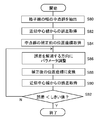
次に、上記構成によって実現できるキャリブレーション装置10の動作を説明する。図6は、キャリブレーション装置10が撮像装置のパラメータを特定する処理手順を示すフローチャートである。まず撮影画像取得部30は、撮像装置12からチャート200を撮影した画像のデータを取得する(S10)。撮像装置12が多眼カメラの場合は、各カメラが撮影した画像のデータを取得する。このデータは、チャート200をおよそ正面から撮影した画像でよく、撮影時に厳密な位置合わせをする必要はない。
Next, the operation of the calibration device 10 that can be realized by the above configuration will be described. FIG. 6 is a flowchart showing a processing procedure in which the calibration device 10 specifies the parameters of the imaging device. First, the photographed image acquisition unit 30 acquires data of an image obtained by photographing the chart 200 from the imaging device 12 (S10). When the imaging device 12 is a multi-view camera, data of an image captured by each camera is acquired. This data may be an image of the chart 200 taken approximately from the front, and it is not necessary to perform precise alignment at the time of shooting.
姿勢・歪み補正部34は、撮影画像を補正し元のチャートのパターンに近づけることで、撮像装置に係る上述したパラメータを取得する(S12)。上述のとおり撮影画像の歪みには、撮像装置12の姿勢によるものと、魚眼レンズなど撮像装置12の構造によるものとが含まれる。したがって、補正に必要なパラメータを仮定して両者を解消する補正を順に施し、得られた補正後のデータがチャートのパターンと略同一になるまでパラメータを調整していくことで、最終的な補正後の画像とパラメータの値を取得する。ただし撮像装置12の位置は歪みの補正には用いないため、この段階では判明しない。なお撮像装置12の位置を求める必要がない場合、次に述べるS14~S18の処理は省略できる。
The posture / distortion correction unit 34 acquires the above-described parameters relating to the imaging device by correcting the captured image and bringing it close to the original chart pattern (S12). As described above, distortion of a captured image includes that due to the posture of the imaging device 12 and that due to the structure of the imaging device 12 such as a fisheye lens. Therefore, assuming the parameters necessary for correction, corrections to eliminate both are sequentially performed, and the parameters are adjusted until the obtained data after correction becomes substantially the same as the pattern of the chart, final correction Get the image and parameter values after. However, since the position of the imaging device 12 is not used for distortion correction, it is not known at this stage. When it is not necessary to obtain the position of the imaging device 12, the processes of S14 to S18 described below can be omitted.
次に疑似画像描画部42は、チャート画像記憶部40からチャート200のモデルデータを読み出し仮想空間に配置したうえ、仮想カメラがそれを撮影した画像を疑似画像として描画する(S14)。このとき仮想カメラの姿勢は、S12で取得した値とし、位置については仮の値を与えておく。また当該仮想カメラも魚眼レンズとし、撮像装置12と同じ画角、レンズ歪み補正係数、レンズ中心の位置、接線歪み補正係数を有するとする。これに従いモデル上のチャートを射影して歪みをつけることにより、S10で取得した撮影画像に類似の画像を生成できる。
Next, the pseudo image drawing unit 42 reads out the model data of the chart 200 from the chart image storage unit 40 and arranges it in a virtual space, and draws an image of the image taken by the virtual camera as a pseudo image (S14). At this time, the attitude of the virtual camera is a value acquired in S12, and a temporary value is given for the position. The virtual camera is also a fisheye lens, and has the same angle of view as the imaging device 12, a lens distortion correction coefficient, a position of the lens center, and a tangential distortion correction coefficient. By projecting the chart on the model according to this and applying distortion, it is possible to generate an image similar to the photographed image acquired in S10.
次に姿勢・歪み補正部34は、S14で描画された疑似画像を、S12と同様に補正する(S16)。すなわちS12で得られたパラメータを用いて歪みを解消する補正を施す。これによりチャートのパターンに近い画像が得られるが、画像上でのチャートの位置や倍率は、疑似画像の描画時に設定した仮想カメラの位置に依存している。視点調整部44は、S12で取得した撮影画像の補正後の画像におけるマーカーの位置および格子の間隔と、S16で取得した疑似画像の補正後の画像におけるマーカーの位置および格子の間隔が略同一になるように仮想カメラの位置を調整する(S18)。
Next, the posture / distortion correction unit 34 corrects the pseudo image drawn in S14 as in S12 (S16). That is, correction for eliminating distortion is performed using the parameters obtained in S12. As a result, an image close to the pattern of the chart is obtained, but the position and magnification of the chart on the image depend on the position of the virtual camera set at the time of drawing the pseudo image. The viewpoint adjustment unit 44 sets the marker positions and lattice intervals in the corrected image of the captured image acquired in S12 to be substantially the same as the marker positions and lattice intervals in the pseudo image acquired in S16. The position of the virtual camera is adjusted to be (S18).
両者の差が所定のしきい値以下となったときの仮想カメラの位置を、実際の撮像装置12の位置として取得する。出力データ生成部46は、それまでの処理で得られたパラメータ自体や、それを用いて行った画像解析や情報処理の結果を表すデータを生成し出力する(S20)。上述のとおり出力先は、ゲームや表示などその他の処理を実行する装置でもよいし、記憶装置でもよい。あるいは撮像装置12自体でもよい。
The position of the virtual camera when the difference between the two becomes equal to or less than a predetermined threshold value is acquired as the actual position of the imaging device 12. The output data generation unit 46 generates and outputs data representing the parameter itself obtained by the processing up to that point and the result of the image analysis and information processing performed using the parameter (S20). As described above, the output destination may be a device that executes other processing such as a game or display, or may be a storage device. Alternatively, the imaging device 12 itself may be used.
次に、歪み補正部34が図6のS12において行う撮影画像の補正手法について説明する。図7は実際の撮影画像が補正される様子を例示している。撮影画像50に写るチャートは、図1で説明したように、白い背景上に所定幅を有する黒い直線を格子状に表し、さらに当該格子線で囲まれた矩形のうちの1つに黒い矩形のマーカーを表したパターンを有する。撮像装置12を魚眼レンズとすることにより、レンズの中心に対応する画像平面の略中心から離れるほど像が縮小されている。
Next, the correction method of the captured image performed by the distortion correction unit 34 in S12 of FIG. 6 will be described. FIG. 7 illustrates how the actual captured image is corrected. The chart shown in the photographed image 50 represents a black straight line having a predetermined width on a white background in a grid, as described in FIG. 1, and further has a black rectangle as one of the rectangles surrounded by the grid. It has a pattern representing a marker. By using the imaging device 12 as a fisheye lens, the image is reduced as it goes away from the approximate center of the image plane corresponding to the center of the lens.
歪み補正部34は撮影画像50を補正し、本来のチャートパターンに近い状態、すなわち黒い直線が等間隔で直交している補正後の画像52を生成する。上述のとおり画像端に向かう像の縮小度合い、ひいては直線の曲がり具合は撮像装置12の画角やレンズ中心の位置のずれなど、主に撮像装置12の内部構造に依存し、画像平面の水平方向、垂直方向に対する格子の傾斜の度合いは撮像装置12の姿勢に依存する。したがって撮影画像50から画像52に補正する過程でそれらのパラメータを導出できる。
The distortion correction unit 34 corrects the photographed image 50, and generates a corrected image 52 in a state close to the original chart pattern, that is, black straight lines are orthogonal at equal intervals. As described above, the degree of reduction of the image toward the image edge, and hence the degree of bending of the straight line, mainly depends on the internal structure of the imaging device 12 such as the angle of view of the imaging device 12 and the position of the lens center, The degree of inclination of the grid with respect to the vertical direction depends on the attitude of the imaging device 12. Therefore, those parameters can be derived in the process of correcting the photographed image 50 into the image 52.
図8は、歪み補正部34の補正による概念的な画像の変遷を示している。当該補正は上述のとおり、撮影画像60におけるレンズ歪みを解消して格子が直線状の画像62を生成し(S30)、それを射影変換することにより格子が直交する補正後の画像64を得る処理である(S32)。画像処理としては、撮影画像60上の位置座標を入力して、補正後の画像64上の位置座標を出力する処理となる。また本実施の形態では、S30の処理により格子が直線状の画像となるように撮像装置12の画角や補正係数等を模索し、S32の処理により格子が直交するように撮像装置12の元の姿勢を模索する。
FIG. 8 shows the transition of a conceptual image due to the correction of the distortion correction unit 34. As described above, this correction is a process of eliminating lens distortion in the captured image 60 to generate a linear image 62 of the lattice (S30), and project-transforming it to obtain the corrected image 64 in which the lattice is orthogonal (S32). The image processing is processing for inputting position coordinates on the photographed image 60 and outputting position coordinates on the image 64 after correction. Further, in the present embodiment, the angle of view, correction coefficient, and the like of the imaging device 12 are searched so that the lattice becomes a linear image by the process of S30, and the original of the imaging device 12 is made to be orthogonal To explore the attitude of
すなわち、画像62、64のように目標となる画像での直線性や直交性を評価したうえ、各種パラメータを調整した場合に当該直線性や直交性がどのように改善されるかを確認する処理が含まれる。このとき評価対象の画像62、64上の位置座標を入力して、撮影画像60上の元の位置座標を出力する処理経路を準備しておくと、調整処理を効率化できる。すなわち補正後の画像64に逆の射影変換を施し(S34)、レンズ歪みをつける(S36)処理経路を準備する。
That is, processing for evaluating the linearity and orthogonality in the target image as in the images 62 and 64, and confirming how the linearity and orthogonality are improved when various parameters are adjusted. Is included. At this time, if position coordinates on the images 62 and 64 to be evaluated are input to prepare a processing path for outputting the original position coordinates on the photographed image 60, the adjustment processing can be made efficient. That is, inverse projective transformation is applied to the image 64 after correction (S34), and lens distortion is applied (S36) to prepare a processing path.
歪み補正部34は、これらの処理を適宜使い分けることにより、補正後の画像64を効率的に生成する。以後、S30、S32のように歪みのある画像からチャートパターンの画像を生成する処理経路を「順方向補正」、S34、S36のようにチャートパターンの画像から歪みのある画像を生成する処理経路を「逆方向補正」と呼ぶ。
The distortion correction unit 34 efficiently generates the corrected image 64 by properly using these processes. Thereafter, the processing path for generating the chart pattern image from the distorted image as in S30 and S32 is “forward direction correction”, and the processing path for generating the distorted image from the chart pattern image as in S34 and S36 It is called "reverse direction correction".
図9は、歪み補正部34が撮影画像を補正する処理手順を示すフローチャートである。この処理は図6のS12に対応する。まず補正後の画像の平面を準備するとともに(S40)、補正に用いるパラメータを仮に設定する(S42)。具体的には撮像装置12の画角、姿勢(パン角、チルト角、ロール角)、レンズ歪み補正係数、レンズ中心の位置、接線歪み補正係数を設定する。多くの場合、レンズ歪みはレンズ歪み補正係数k2、k4、k6を用いて次式により補正される。
i' = i (1 + k2 * r2 + k4 * r4 + k6 * r6)/(1 + k2 + k4 + k6)
j' = j (1 + k2 * r2 + k4 * r4 + k6 * r6)/(1 + k2 + k4 + k6) FIG. 9 is a flowchart showing a processing procedure for thedistortion correction unit 34 to correct a captured image. This process corresponds to S12 of FIG. First, the plane of the image after correction is prepared (S40), and parameters used for correction are temporarily set (S42). Specifically, the angle of view, posture (pan angle, tilt angle, roll angle), lens distortion correction coefficient, lens center position, and tangent distortion correction coefficient of the imaging device 12 are set. In most cases, lens distortion is corrected by the following equation using lens distortion correction coefficients k2, k4, and k6.
i '= i (1 + k2 * r 2 + k4 *r 4 + k6 * r 6) / (1 + k2 + k4 + k6)
j '= j (1 + k2 * r 2 + k4 *r 4 + k6 * r 6) / (1 + k2 + k4 + k6)
i' = i (1 + k2 * r2 + k4 * r4 + k6 * r6)/(1 + k2 + k4 + k6)
j' = j (1 + k2 * r2 + k4 * r4 + k6 * r6)/(1 + k2 + k4 + k6) FIG. 9 is a flowchart showing a processing procedure for the
i '= i (1 + k2 * r 2 + k4 *
j '= j (1 + k2 * r 2 + k4 *
ここで(i,j)は歪みのある画像における位置座標、(i’,j’)はその補正後の位置座標、rは補正前の画像における位置座標(i,j)の、レンズ中心からの距離であり、レンズ中心の位置座標を(ic,jc)とすると次の式で定義される。
r = ((i - ic)2 + (j - jc)2)1/2
なお上記は6次までの補正を示しているが、補正の次数は限定されない。一方、接線歪みは接線歪み補正係数p1、p2を用いて次式により補正される。
i' = i + (2p1 * ij + p2 (r2 + 2i2))
j' = j + (p1 (r2 + 2j2) + 2p2 * ij)
すなわちこれらの式を用いると、レンズ中心からの距離のみに依存した補正がなされる。 Here, (i, j) is the position coordinate in the distorted image, (i ', j') is the position coordinate after the correction, and r is the lens center of the position coordinate (i, j) in the image before the correction When the position coordinates of the lens center are (ic, jc), the distance is defined by the following equation.
r = ((i-ic) 2 + (j-jc) 2 ) 1/2
Although the above shows the correction up to the sixth order, the order of the correction is not limited. On the other hand, tangential distortion is corrected by the following equation using tangential distortion correction coefficients p1 and p2.
i '= i + (2p1 * ij + p2 (r 2 + 2i 2 ))
j '= j + (p1 ( r 2 + 2j 2) + 2p2 * ij)
That is, using these equations, correction dependent on only the distance from the lens center is made.
なお後述するように、本実施の形態では魚眼レンズによる歪みを、まず射影方式の違いを考慮して補正し、さらに上式により補正することで補正精度を向上させる。次に、S42で設定した仮のパラメータを用いたときの補正画像を、S40で準備した画像平面に描画する(S44)。この処理には、当該画像平面における各画素の位置座標を入力値として、撮影画像上の対応する位置座標を求める逆方向補正の処理経路を利用する。これにより、仮設定されたパラメータを用いて補正された、チャートパターンに近い画像が生成される。
As described later, in the present embodiment, the distortion due to the fisheye lens is first corrected in consideration of the difference in projection method, and the correction accuracy is improved by further correcting according to the above equation. Next, a corrected image when using the temporary parameters set in S42 is drawn on the image plane prepared in S40 (S44). In this process, using a position coordinate of each pixel on the image plane as an input value, a processing path of reverse direction correction for obtaining a corresponding position coordinate on the photographed image is used. As a result, an image close to the chart pattern corrected using the temporarily set parameters is generated.
次に、当該画像において、チャートパターンの格子を構成する直線を探索する(S46)。S42で設定した撮像装置12の姿勢が実際と異なっている場合、それらの直線は直交しないため、直交するまで姿勢の設定を調整していく(S48)。ただしここでは、最も外側に検出された上下左右の4直線の交点のみを監視しながら姿勢の設定を調整することにより処理効率を上げる。これにより撮像装置12の姿勢が判明する。S42で設定した姿勢以外のパラメータが実際と異なっている場合、S48で生成した画像における格子線はなお、微小量歪曲していたり傾斜していたりする。したがってそれらの歪みが解消されるまで、当該パラメータの設定を調整していく(S50)。
Next, in the image, a straight line forming a grid of the chart pattern is searched (S46). When the attitude of the imaging device 12 set in S42 is different from the actual one, since those straight lines are not orthogonal, the setting of the attitude is adjusted until it is orthogonal (S48). However, in this case, the processing efficiency is improved by adjusting the setting of the posture while monitoring only the intersections of the four straight lines vertically and horizontally detected on the outermost side. Thereby, the attitude of the imaging device 12 is determined. When the parameters other than the posture set in S42 are different from the actual ones, the grid lines in the image generated in S48 are still distorted or inclined by a small amount. Therefore, the setting of the parameters is adjusted until the distortion is eliminated (S50).
この場合も、格子線の幅を2分する点を所定間隔でサンプリングし、それらの近似直線に対する誤差のみを監視しながらパラメータの設定を調整することにより処理効率を上げる。これにより撮像装置12の画角、補正係数、レンズ中心の位置が判明する。S48、S50の処理により、S42で設定したパラメータが更新されるため、当該更新値を用いて再度、S44と同様の描画処理を実施することにより、最終的な補正後の画像を生成する(S52)。このとき、当該画像に対し格子線とマーカーの検出を行うことにより、格子線の間隔とマーカーのサイズも特定しておく。補正後の画像のデータは画像記憶部36に、更新されたパラメータはパラメータ記憶部38に、それぞれ格納する。
Also in this case, processing efficiency is improved by sampling the points dividing the width of the grid line at predetermined intervals and adjusting the setting of parameters while monitoring only the error with respect to their approximate straight line. Thereby, the angle of view of the imaging device 12, the correction coefficient, and the position of the lens center are determined. Since the parameters set in S42 are updated by the processes of S48 and S50, a final corrected image is generated by performing the same drawing process as S44 using the updated value again (S52) ). At this time, the grid line spacing and the marker size are also specified by detecting the grid lines and the markers on the image. The data of the image after correction is stored in the image storage unit 36, and the updated parameter is stored in the parameter storage unit 38.
図10は、図8のS32における射影変換の処理を説明するための図である。(a)はチャート200と、撮像装置12の視点205および視線ベクトル207を含む3次元空間を示している。なおここでの視線ベクトル207は撮像装置の光軸が向く方向を規定する。図示する例では、視点205の位置座標(x,y,z)は、チャート200に平行なXZ平面とチャートの中心で垂直に交わるY軸がなす3次元空間で定義される。3次元空間の原点Oは、Y軸方向を視線ベクトルとしたときにチャートパターンが視野全体に表示されるときの視点とする。換言すれば、視点が原点Oにあり視線ベクトルがY軸と重なる(撮像装置12がチャート200に正対する)基準状態において、図8の補正後の画像64が得られる。
FIG. 10 is a diagram for explaining the process of projective transformation in S32 of FIG. (A) shows a three-dimensional space including the chart 200, the viewpoint 205 of the imaging device 12, and the gaze vector 207. Here, the line-of-sight vector 207 defines the direction in which the optical axis of the imaging device is directed. In the illustrated example, position coordinates (x, y, z) of the viewpoint 205 are defined in a three-dimensional space formed by an XZ plane parallel to the chart 200 and a Y axis perpendicular to the center of the chart. The origin O of the three-dimensional space is a viewpoint when the chart pattern is displayed over the entire visual field when the Y-axis direction is a gaze vector. In other words, the corrected image 64 of FIG. 8 is obtained in the reference state in which the viewpoint is at the origin O and the line-of-sight vector overlaps the Y axis (the imaging device 12 faces the chart 200).
同図(b)には、視線ベクトル207を拡大したうえ、撮像装置12の姿勢を定義するパラメータを示している。視点205からチャート200への垂線L(Y軸方向)を基準としてパン角p、チルト角qが定義され、視線ベクトル207の回転方向にロール角rが定義される。視点205と視線ベクトル207が標準状態へ変位するときの画像上の位置座標の変化は、これらのパラメータを用いて一般的な射影変換行列により求めることができる。
FIG. 7B shows parameters for defining the attitude of the imaging device 12 after enlarging the sight line vector 207. A pan angle p and a tilt angle q are defined on the basis of a perpendicular L (the Y-axis direction) from the viewpoint 205 to the chart 200, and a roll angle r is defined in the rotation direction of the line-of-sight vector 207. Changes in position coordinates on the image when the viewpoint 205 and the gaze vector 207 are displaced to the standard state can be obtained by a general projective transformation matrix using these parameters.
始点となる視点205および視線ベクトル207が既知であれば、当該射影変換により図8の補正後の画像64が得られる。本実施の形態では視点205と視線ベクトル207が未知のため、それらを定義するパラメータを仮に設定して変換後の画像を確認し、目的とするチャートパターンの画像が得られるように設定パラメータを調整する。これにより、視点205と視線ベクトル207、ひいては撮像装置12の位置と姿勢を特定できる。
If the viewpoint 205 and the gaze vector 207 as the starting point are known, the image 64 after correction of FIG. 8 is obtained by the projective transformation. In this embodiment, since the viewpoint 205 and the gaze vector 207 are unknown, the parameters defining them are temporarily set, the converted image is confirmed, and the setting parameters are adjusted so that the image of the target chart pattern can be obtained. Do. As a result, it is possible to specify the viewpoint 205 and the gaze vector 207, and hence the position and orientation of the imaging device 12.
図11は、図8のS30における歪み補正の処理を説明するための図である。魚眼レンズの場合は特に、上述した補正式による一般的な歪み補正では、光軸からの距離が大きい画像端部において補正量が不足し、歪みの解消が十分でない場合がある。そこで本実施の形態では、魚眼レンズ特有の歪みを、射影方式を考慮して補正したうえで、一般的な補正式を適用する。同図は、視点74と、直線ABで表される中心射影のスクリーン面70、弧A2B2で表される魚眼レンズの等距離射影のスクリーン面72を俯瞰した状態を示している。
FIG. 11 is a diagram for explaining the distortion correction process in S30 of FIG. In the case of a fisheye lens, in particular, in general distortion correction according to the above-described correction formula, the correction amount may be insufficient at the image end where the distance from the optical axis is large, and the distortion may not be sufficiently eliminated. So, in this embodiment, after correcting distortion peculiar to a fisheye lens in consideration of a projection system, a general correction formula is applied. This figure shows the viewpoint 74, the screen surface 70 of the central projection represented by the straight line AB, and the screen surface 72 of the equidistant projection of the fisheye lens represented by the arc A2B2.
画角をθとしたときの中心射影の水平画素数Nhの画像における左右の端がAおよびBであり、それに対応する魚眼レンズの画像における左右の端がA2およびB2である。視点74から画像までの距離fは、画素を単位として次の式で表される。
f = Nh / ( 2 * (tan (q / 2))
等距離射影のスクリーン面72上の点P(i1,j1)と、それに対応する中心射影のスクリーン面70上の点Q(i2,j2)は、それぞれの画像中心(厳密にはレンズ中心の位置)Cからの距離r1、r2と次の関係にある。
r1 = f * atan (r2 / f)
r2 = (i2 + j2)1/2
ここでatan(r2/f)は、補正前後の点P(i1,j1)および点Q(i2,j2)への視線ベクトルと光軸がなす角度を表す。距離r2に対する距離r1の割合sは点Q(i2,j2)の位置座標を用いて次のように求められる。
s = r1 / r2 = (f * atan (r2 / f)) / r2 The left and right ends of the image of the horizontal projection pixel number Nh of the center projection when the angle of view is θ are A and B, and the left and right ends of the image of the corresponding fisheye lens are A2 and B2. The distance f from theviewpoint 74 to the image is expressed by the following equation in pixel units.
f = Nh / (2 * (tan (q / 2))
The point P (i1, j1) on the screen surface 72 of the equidistant projection and the point Q (i2, j2) on thescreen surface 70 of the corresponding central projection are the respective image centers (strictly speaking, the positions of the lens centers) And the distances r1 and r2 from C).
r1 = f * atan (r2 / f)
r2 = (i2 + j2) 1/2
Here, a tan (r 2 / f) represents an angle formed by the sight axis vector to the point P (i 1, j 1) and the point Q (i 2, j 2) before and after the correction and the optical axis. The ratio s of the distance r1 to the distance r2 is determined as follows using the position coordinates of the point Q (i2, j2).
s = r1 / r2 = (f * atan (r2 / f)) / r2
f = Nh / ( 2 * (tan (q / 2))
等距離射影のスクリーン面72上の点P(i1,j1)と、それに対応する中心射影のスクリーン面70上の点Q(i2,j2)は、それぞれの画像中心(厳密にはレンズ中心の位置)Cからの距離r1、r2と次の関係にある。
r1 = f * atan (r2 / f)
r2 = (i2 + j2)1/2
ここでatan(r2/f)は、補正前後の点P(i1,j1)および点Q(i2,j2)への視線ベクトルと光軸がなす角度を表す。距離r2に対する距離r1の割合sは点Q(i2,j2)の位置座標を用いて次のように求められる。
s = r1 / r2 = (f * atan (r2 / f)) / r2 The left and right ends of the image of the horizontal projection pixel number Nh of the center projection when the angle of view is θ are A and B, and the left and right ends of the image of the corresponding fisheye lens are A2 and B2. The distance f from the
f = Nh / (2 * (tan (q / 2))
The point P (i1, j1) on the screen surface 72 of the equidistant projection and the point Q (i2, j2) on the
r1 = f * atan (r2 / f)
r2 = (i2 + j2) 1/2
Here, a tan (r 2 / f) represents an angle formed by the sight axis vector to the point P (i 1, j 1) and the point Q (i 2, j 2) before and after the correction and the optical axis. The ratio s of the distance r1 to the distance r2 is determined as follows using the position coordinates of the point Q (i2, j2).
s = r1 / r2 = (f * atan (r2 / f)) / r2
中心から画像端までの長さの割合Rは
R = (2f * atan( Nh/2f )) / Nh
であるから、正規化された割合s’は次にようになる。
s' = s / R = ( Nh / 2r2) * ( atan (r2 / f) / atan ( Nh / 2f))
この演算は、画像中心からの距離に基づく一般的な補正式に対し、光軸に対する視線ベクトルの角度に基づいている。すなわち画像の平面上での情報のみならず、それと視点との関係を考慮した3次元での情報を用いて画像を補正できる。 The ratio R of the length from the center to the image edge is R = (2f * atan (Nh / 2f)) / Nh
So, the normalized fraction s' is
s' = s / R = (Nh / 2r2) * (atan (r2 / f) / atan (Nh / 2f))
This operation is based on the angle of the line-of-sight vector with respect to the optical axis, as opposed to a general correction equation based on the distance from the image center. That is, the image can be corrected using not only the information on the plane of the image but also the three-dimensional information in consideration of the relationship between it and the viewpoint.
これにより、画像上での位置によらず正確な補正を実現できる。なお割合s’は補正後の点Q(i2,j2)を既知として求められる。これは実際の処理では、中心射影のスクリーン面70を先に準備し、当該面上の画素の位置座標に割合s’を乗算することにより、補正前の魚眼レンズの画像における参照先を特定するためである。このようにして参照先の画素値を引いてくることにより、補正後の画像を生成できる。
As a result, accurate correction can be realized regardless of the position on the image. The ratio s' can be obtained with the corrected point Q (i2, j2) as known. In actual processing, the screen surface 70 of the central projection is prepared first, and the reference position in the image of the fisheye lens before correction is specified by multiplying the position coordinates of the pixels on the surface by the ratio s ′. It is. By subtracting the pixel value of the reference destination in this manner, it is possible to generate an image after correction.
このように魚眼レンズによる歪みを解消してもなお、レンズの固体差や組み付け具合による歪みが残るため、上述したレンズ中心からの距離に基づく一般的な補正式を用いて補正する。ただし魚眼レンズの歪みを上述のとおり補正した場合、レンズ歪み補正式のうち2次の項を省略する。本実施の形態ではこれらの処理をセットとして歪み補正を行うことにより、画像の端まで高い精度で歪みが解消された画像を得ることができる。この補正には、撮像装置の画角、レンズ歪み補正係数、レンズ中心の位置、接線歪み補正係数が用いられるため、一旦それらのパラメータを仮定して補正を実施し、その結果として格子線が十分な精度で直線に近づくまで調整することで、最終的なパラメータの値を決定する。
As described above, even if distortion due to the fisheye lens is eliminated, distortion due to the difference between the lens and the degree of assembly remains, so correction is performed using the general correction formula based on the distance from the lens center described above. However, when distortion of the fisheye lens is corrected as described above, the second term of the lens distortion correction equation is omitted. In the present embodiment, by performing distortion correction using the above-described processes as a set, it is possible to obtain an image in which distortion is eliminated with high accuracy up to the end of the image. Since this correction uses the angle of view of the imaging device, the lens distortion correction coefficient, the position of the lens center, and the tangent distortion correction coefficient, correction is once performed assuming these parameters, and as a result, the grid lines are sufficiently The final parameter value is determined by adjusting until it approaches a straight line with high accuracy.
図示する例では、魚眼レンズの画角θを100°程度に限定しているため、中心射影のスクリーン面70への変換が容易である。一方、魚眼レンズを用いたカメラは、視点に対し360°の画角での画像が一度に得られるという利点がある。この特性を活かすため、中心射影のスクリーン面を拡張することが考えられる。図12は、拡張された中心射影のスクリーン面と魚眼レンズのスクリーン面の関係を例示している。同図は図11と同様、視点74と各スクリーン面の俯瞰図であるが、画角を360°とすることで、魚眼レンズのスクリーン面76が、焦点距離fを半径とする球面全体となる。
In the illustrated example, since the angle of view θ of the fisheye lens is limited to about 100 °, conversion of the central projection onto the screen surface 70 is easy. On the other hand, a camera using a fisheye lens has an advantage that an image at an angle of view of 360 ° with respect to the viewpoint can be obtained at one time. In order to take advantage of this property, it is conceivable to extend the screen plane of central projection. FIG. 12 illustrates the relationship between the screen surface of the expanded central projection and the screen surface of the fisheye lens. This figure is an overhead view of the viewpoint 74 and each screen surface as in FIG. 11. However, by setting the angle of view to 360 °, the screen surface 76 of the fisheye lens becomes an entire spherical surface whose radius is the focal distance f.
この場合、画像全体を補正するため、球面のスクリーン面76に外接する立方体の6面の内壁を中心射影のスクリーン面とする(例えばスクリーン面78a、78b、78c、78d)。そして視点74を頂点とし内壁の各面を底面とする四角錐状に空間を領域分割し、球面のスクリーン面76上の対象画素がどの領域に属するかによって、変換先のスクリーン面を選択する。図ではスクリーンを俯瞰しているため、視点74周りで90°ごとの4象限に分割されている。球面のスクリーン面76のうち第I象限に属する画像はスクリーン面78a上での画像に補正する。第II、III、IV象限に属する画像はそれぞれ、スクリーン面78b、78c、78d上での画像に補正する。
In this case, in order to correct the entire image, the six inner walls of the cube circumscribed to the spherical screen surface 76 are used as the screen surfaces of the center projection (for example, screen surfaces 78a, 78b, 78c, 78d). Then, the space is divided into quadrilateral pyramids with the viewpoint 74 as the apex and each surface of the inner wall as the bottom, and the screen surface to be converted is selected depending on which region the target pixel on the screen surface 76 of the spherical belongs. In the figure, since the screen is overlooked, it is divided into four quadrants of 90 ° around the viewpoint 74. An image belonging to the first quadrant of the spherical screen surface 76 is corrected to an image on the screen surface 78a. Images belonging to quadrants II, III, and IV are corrected to images on screen surfaces 78b, 78c, and 78d, respectively.
各象限における補正の計算は上述したのと同様でよい。チャート200も立方体の内壁にチャートパターンを表した形態とし、その中央に撮像装置12を配置して撮影すれば、本実施の形態のその他の処理についても象限ごとに同様に行える。これにより画角の制限なしに、魚眼レンズの画像をほぼ歪みのない画像に補正できる。画角が360°の場合に限らず、それより小さい任意の画角に対し適切な枚数の平面を準備すれば、同じように補正できる。また準備する平面は立方体の面に限らず、球面のスクリーン面76に外接する多面体や、球面のスクリーン面76に外接する円筒形などでもよい。
The calculation of the correction in each quadrant may be similar to that described above. If the chart 200 also has a form in which a chart pattern is represented on the inner wall of a cube and the imaging device 12 is placed at the center of the cube and photographed, the other processes of the present embodiment can be similarly performed for each quadrant. This makes it possible to correct a fisheye lens image to a substantially distortion-free image without any restriction on the angle of view. The same correction can be made by preparing an appropriate number of planes for any angle of view smaller than that, not limited to the case where the angle of view is 360 °. The plane to be prepared is not limited to the cube plane, and may be a polyhedron circumscribing the spherical screen surface 76 or a cylinder circumscribing the spherical screen surface 76.
この手法は、これまで述べたような補正係数を特定する目的以外に、運用時に撮影された画像から歪みのない画像を生成し表示させる態様にも適用できる。例えばヘッドマウントディスプレイに魚眼レンズの撮像装置を設け、撮影された画像をそのまま表示したり仮想オブジェクトを描画して表示したりする場合、一旦、中心射影のスクリーン上での画像に補正する。そして各スクリーン上で必要な加工を行ったうえ、ユーザの視線に対応するビュースクリーンに射影し直すことで、歪みのない画像を効率的に表示できる。
This method can be applied not only to the purpose of specifying the correction coefficient as described above, but also to an aspect in which an image without distortion is generated and displayed from an image taken at the time of operation. For example, when an imaging device of a fisheye lens is provided on a head mounted display, and a photographed image is displayed as it is or a virtual object is drawn and displayed, the image is temporarily corrected to an image on a center projection screen. Then, by performing necessary processing on each screen and reprojecting on the view screen corresponding to the line of sight of the user, it is possible to efficiently display an image without distortion.
これまでの説明は主に、図8におけるS30、S32の順方向補正を想定した。一方、図9のS44における処理は、補正後の画像平面における画素値を決定するため、その位置座標から撮影画像の位置座標を求める逆方向補正となる。S48において格子線が直交するように姿勢の設定を調整する処理や、S50において歪みが解消されるように補正パラメータを調整する処理も、逆方向補正を用いることにより、仮に補正された画像上でサンプリングされた特定の画素のみを対象として調整具合を評価でき処理効率を上げられる。
The above description mainly assumes the forward correction of S30 and S32 in FIG. On the other hand, the process in S44 of FIG. 9 is reverse correction in which the position coordinate of the photographed image is obtained from the position coordinate in order to determine the pixel value on the image plane after correction. The process of adjusting the setting of the posture so that the grid lines are orthogonal in S48, and the process of adjusting the correction parameter so as to eliminate the distortion in S50 are also performed on the temporarily corrected image by using the reverse correction. The degree of adjustment can be evaluated only for specific pixels sampled, and processing efficiency can be increased.
逆方向補正のうち図8のS34における射影変換は、S32について説明した射影変換行列の逆行列を用いるなどの手段で容易に実現できる。一方、図8のS36の、レンズに起因した歪み補正の逆補正については、特に補正係数による歪み補正式を用いた補正の逆処理が含まれるため工夫を要する。本実施の形態では上述のとおり、「魚眼レンズ特有の歪み補正と補正係数を用いた補正」をセットで実施している。逆補正においても当該セットをそのまま用いて、実質的に逆の補正となるようにする。
Of the backward corrections, the projective transformation at S34 of FIG. 8 can be easily realized by means such as using the inverse of the projective transformation matrix described for S32. On the other hand, with regard to the reverse correction of distortion correction caused by the lens in S36 of FIG. 8, a reverse process of the correction using the distortion correction equation by the correction coefficient is included, and ingenuity is required. In the present embodiment, as described above, "a distortion correction unique to a fisheye lens and a correction using a correction coefficient" are performed as a set. Also in the reverse correction, the set is used as it is so as to be substantially reverse correction.
図13は、レンズの歪み補正の逆補正の手法を説明するための図である。同図上段に示すように、この処理は、レンズ歪みのない画像82上の点Q(i2,j2)から、レンズ歪みのある画像80における対応する点P(i1,j1)を求める処理である(矢印B)。レンズ歪みを解消する順方向の補正(矢印A)は上述したとおりであり、逆補正においてもこれをそのまま利用する。
FIG. 13 is a diagram for explaining a method of inverse correction of lens distortion correction. As shown in the upper part of the figure, this processing is processing for obtaining the corresponding point P (i1, j1) in the image 80 with lens distortion from the point Q (i2, j2) in the image 82 without lens distortion. (Arrow B). The correction in the forward direction (arrow A) for eliminating lens distortion is as described above, and this is also used as it is in the reverse correction.
具体的には同図下段に示すように、順方向の補正を施したときの終点が点Q(i2,j2)になるような始点を次のように探索する。まず始点の初期値P0を、目標とする点Q(i2,j2)の位置に仮に定め、上述した順方向の補正を行う。これにより得た終点Q0は当然、目標とする点Q(i2,j2)からずれている。そこで例えば、当該ずれ量の所定割合を点P0の位置座標に乗算することで始点をずらす。当該始点P1に対し再び順方向の補正を施し、終点Q1を得る。
Specifically, as shown in the lower part of the figure, a start point where the end point when correction in the forward direction is made is the point Q (i2, j2) is searched as follows. First, the initial value P0 of the start point is temporarily determined at the position of the point Q (i2, j2) to be a target, and the above-mentioned forward correction is performed. The end point Q0 thus obtained is naturally deviated from the target point Q (i2, j2). Therefore, for example, the start point is shifted by multiplying the position coordinate of the point P0 by a predetermined ratio of the deviation amount. The forward correction is performed again on the start point P1 to obtain an end point Q1.
そして終点Q1と目標とする点Q(i2,j2)のずれ量の所定割合を、点P1の位置座標に乗算することで、さらに始点をずらし順方向の補正を施す。この処理を、終点の位置Qnが目標とする点Q(i2,j2)から所定範囲内に収まるまで繰り返す。収束したときの始点Pnを、歪みのある画像80における逆補正の終点P(i1,j1)とする。
Then, by multiplying the position coordinates of the point P1 by a predetermined ratio of the deviation amount of the end point Q1 and the target point Q (i2, j2), the start point is further shifted to perform correction in the forward direction. This process is repeated until the end point position Qn falls within a predetermined range from the target point Q (i2, j2). The start point Pn at which convergence occurs is taken as the end point P (i1, j1) of the inverse correction in the distorted image 80.
図14は、歪み補正部34が図9のS46において、補正後の画像の格子線を探索する手法の例を説明するための図である。図は当該補正後の画像における中央近傍の領域を拡大して示している。当該画像領域において、例えば画像の中央84を中心とする所定長の線分を定義したうえ、当該線分の角度と位置を変化させながらそれが通る画素値の合計を取得していく。線分全体が格子線の黒い領域に入っていれば画素値は最小になるため、そのような状態の線分86を決定する。
FIG. 14 is a diagram for describing an example of a method in which the distortion correction unit 34 searches for grid lines of the image after correction in S46 of FIG. 9. The figure shows an enlarged area near the center of the image after the correction. In the image area, for example, a line segment of a predetermined length centering on the center 84 of the image is defined, and while changing the angle and position of the line segment, the sum of pixel values passing through is obtained. Since the pixel value is minimized if the entire line segment is in the black area of the grid line, the line segment 86 in such a state is determined.
次に、線分86を中心84で等分してなる2つの線分をそれぞれ、画像平面の下方向に移動させながらそれが通る画素値の合計を取得していく。線分がチャートパターンの白い矩形に入ると、画素値の合計が大きくなる。実際にはしきい値判定によりそのような状態を検出する。同図において当該状態の線分88a、88bを示している。ここで右の線分88bは、左の線分88aより早く白い矩形に到達している。これにより当初の線分86は、チャートパターンの格子線より右下がりになっていることが判明する。そこで線分86を所定角度右上がりにしたうえ、再度それを分割してなる線分を下方向に移動させることにより白い矩形を探索し、到達するタイミングによって元の線分の角度を調整する。
Next, while moving two line segments obtained by equally dividing the line segment 86 at the center 84 downward in the image plane, the sum of the pixel values through which it passes is obtained. When the line segment enters the white rectangle of the chart pattern, the sum of the pixel values increases. In practice, such a state is detected by threshold determination. In the figure, line segments 88a and 88b in the state are shown. Here, the right line segment 88b reaches the white rectangle earlier than the left line segment 88a. As a result, it is found that the initial line segment 86 is downward to the right of the grid line of the chart pattern. Therefore, the line segment 86 is moved upward by a predetermined angle, and the line segment obtained by dividing the line segment is moved downward again to search for a white rectangle, and the angle of the original line segment is adjusted according to the arrival timing.
この処理を所定回数繰り返すことにより、チャートパターンの格子線のうち横線の下端のおよその角度と位置が判明する。同様に、当該角度および位置で線分を定義し、それを分割してなる2つの線分を、画像平面の下方向にさらに移動させながら、それが通る画素値の合計を取得していく。線分がチャートパターンの黒い格子線に入ると、画素値の合計が小さくなる。実際にはしきい値判定によりそのような状態を検出する。同図において当該状態の線分90a、90bを示している。この場合も、どちらが早く到達したかによって角度を調整し、再度黒い格子線を探索する処理を繰り返す。これによりチャートパターンの格子線のうち横線の上端のおよその角度と位置が判明する。
By repeating this process a predetermined number of times, the approximate angle and position of the lower end of the horizontal line among the grid lines of the chart pattern can be determined. Similarly, a line segment is defined by the angle and the position, and the two line segments formed by dividing the line segment are further moved downward in the image plane to obtain the sum of pixel values through which they pass. When the line segment enters the black grid line of the chart pattern, the sum of pixel values decreases. In practice, such a state is detected by threshold determination. Line segments 90a and 90b of the said state are shown in the figure. Also in this case, the angle is adjusted depending on which one arrived earlier, and the process of searching for a black grid line again is repeated. As a result, the approximate angle and position of the upper end of the horizontal line among the grid lines of the chart pattern can be determined.
以後は、それらの直線を基点として上方向および下方向に、角度を調整しながら探索していくことで、格子線のうち横線の上端および下端の傾きおよび位置を全て特定できる。格子線のうち縦線についても同様の処理により、左端および右端の傾きおよび位置を特定できる。図9のS52において最終的な補正後の画像が生成された際も、同様の処理を実施する。この場合、さらにチャートパターンの格子線で囲まれた白い矩形領域のうち、中心が黒い領域を探索することによりマーカーの像を検出する。そしてマーカーのサイズを求めておき、格子線の間隔とともに、撮像装置12の視点位置の取得に用いる。
Thereafter, the inclination and the position of the upper end and the lower end of the horizontal line among the grid lines can be identified by searching while adjusting the angle upward and downward based on the straight lines. The inclination and the position of the left end and the right end can be specified by the same processing for vertical lines among grid lines. The same processing is performed when the final image after correction is generated in S52 of FIG. In this case, the image of the marker is detected by searching for a black area in the white rectangular area surrounded by the grid lines of the chart pattern. Then, the size of the marker is obtained, and is used for acquiring the viewpoint position of the imaging device 12 together with the interval of the grid lines.
上記のように特定した、格子線の境界線の傾きおよび位置を、広い領域で確認することにより微調整し、精度を高めてもよい。図15は、格子線の境界線を表す線を微調整する手法を説明するための図である。同図は探索対象の画像92において検出された、最も外側の4直線を辺とする矩形96と、調整対象の線94を示している。まず線94と矩形96の交点98a、98bを取得する。
The inclination and position of the boundaries of the grid lines, which are specified as described above, may be finely adjusted by confirming in a wide area to improve the accuracy. FIG. 15 is a diagram for describing a method of finely adjusting a line representing a boundary of grid lines. The figure shows a rectangle 96 whose sides are the four outermost straight lines detected in the image 92 to be searched, and a line 94 to be adjusted. First, the intersection points 98a and 98b of the line 94 and the rectangle 96 are acquired.
次に交点98a、98bを始点として画像の中心方向に、線94と同じ傾きで所定長さの線分100a、100bを定義する。そして図14の手法と同様の原理で、線分100a、100bを上方向または下方向に移動させながら、それが通る画素値の合計を取得していく。これにより線分100a、100bが白い矩形に入るタイミングを検出し、その位置に基づき得られる直線の傾き反映させて再度線分を定義し探索を繰り返す。この処理により画像の両端に近い離れた位置で、境界線の傾きおよび位置が検出できるため、これらを結ぶことにより線94の調整後の線とする。
Next, line segments 100a and 100b of a predetermined length with the same inclination as the line 94 are defined in the center direction of the image with the intersection points 98a and 98b as the starting point. Then, in the same principle as the method of FIG. 14, while moving the line segments 100a and 100b upward or downward, the sum of pixel values through which the line segments pass is acquired. As a result, the timing at which the line segments 100a and 100b enter the white rectangle is detected, the inclination of the straight line obtained based on the position is reflected, the line segments are defined again, and the search is repeated. Since the inclination and the position of the boundary can be detected at a position near the both ends of the image by this processing, the line 94 is adjusted after adjustment by connecting these.
図16は、歪み補正部34が図9のS48において、補正後の格子線の像が画像平面の水平および垂直方向と一致するように、撮像装置12の姿勢の設定を調整する処理手順を示すフローチャートである。まず上述のように検出された格子線の境界線のうち、図15の矩形96の各辺を構成する、最も外側の4直線について、画像平面の水平方向あるいは垂直方向からの傾き誤差を求める(S60)。続いてそれらの直線の交点の位置座標を取得し、当該4点の補正前の位置座標を撮影画像上で特定する(S62)。この処理には上述の逆方向補正を適用できる。
FIG. 16 shows a processing procedure in which the distortion correction unit 34 adjusts the setting of the attitude of the imaging device 12 so that the image of the grid line after correction coincides with the horizontal and vertical directions of the image plane in S48 of FIG. It is a flowchart. First of all, among the boundary lines of the grid lines detected as described above, inclination errors from the horizontal direction or the vertical direction of the image plane are determined for the outermost four straight lines forming each side of the rectangle 96 of FIG. S60). Subsequently, the position coordinates of the intersection point of those straight lines are acquired, and the position coordinates of the four points before correction are specified on the photographed image (S62). The reverse correction described above can be applied to this process.
そしてS60で求めた誤差を解消する方向に、撮像装置12の姿勢の設定を調整し(S64)、当該姿勢を仮定して4点の位置座標を補正する(S66)。そして補正後の位置座標を頂点とする矩形の各辺について、画像平面の水平方向あるいは垂直方向からの傾き誤差を再度求める(S68)。誤差が所定のしきい値以上の場合(S70のN)、S64からS68の処理を繰り返す。誤差がしきい値より小さくなったら、設定された姿勢が正しいとして処理を終了する(S70のY)。これにより、僅か4点の補正状況を追跡することにより、撮像装置12の姿勢を正確に求めることができる。
Then, the setting of the attitude of the imaging device 12 is adjusted in the direction to eliminate the error obtained in S60 (S64), and the position coordinates of the four points are corrected assuming the attitude (S66). Then, with respect to each side of the rectangle having the position coordinates after correction as vertexes, an inclination error from the horizontal direction or the vertical direction of the image plane is obtained again (S68). If the error is equal to or greater than the predetermined threshold (N in S70), the processes in S64 to S68 are repeated. If the error is smaller than the threshold value, the processing is ended assuming that the set posture is correct (Y in S70). Thus, the posture of the imaging device 12 can be accurately determined by tracking only four correction situations.
図17は、歪み補正部34が図9のS50において、画角および歪み補正の係数を調整する処理手順を示すフローチャートである。上述したように、本実施の形態では撮影画像からレンズに起因した歪みを解消するため、魚眼レンズ特有の歪み補正と補正係数を用いた補正を実施する。これらの補正には、撮像装置の画角と補正係数を用いる。一方、図9のS44における処理では、仮に設定された値を用いているため、格子線が歪曲していたり傾いていたりすることがあり得る。そこで格子線の直線性を確認しながらそれらのパラメータを調整することで、正しいパラメータを導出する。
FIG. 17 is a flowchart showing a processing procedure in which the distortion correction unit 34 adjusts the angle of view and the distortion correction coefficient in S50 of FIG. As described above, in the present embodiment, in order to eliminate distortion caused by the lens from the photographed image, distortion correction unique to a fisheye lens and correction using a correction coefficient are performed. For these corrections, the angle of view of the imaging apparatus and the correction coefficient are used. On the other hand, in the processing at S44 in FIG. 9, since the values set temporarily are used, the grid lines may be distorted or inclined. Therefore, correct parameters are derived by adjusting the parameters while checking the linearity of the grid lines.
まず図14、15で説明したように検出された、チャートパターンの格子線の境界線の情報を利用して、当該格子線の幅を2等分する中点群を所定の間隔で抽出していく(S80)。次に抽出した中点群を最小二乗法等で直線に近似したうえ、各中点から直線までの距離の合計を誤差として取得する(S82)。さらに中点群の補正前の位置座標を、撮影画像上で特定する(S84)。この処理には上述の逆方向補正を適用できる。そしてS82で求めた誤差を解消する方向に各パラメータを調整し(S86)、それを用いて補正したときの補正後の中点群の位置座標を求める(S88)。
First, using the information of the boundary line of the grid line of the chart pattern detected as described in FIGS. 14 and 15, the middle point group which bisects the width of the grid line is extracted at a predetermined interval. Go (S80). Next, the extracted middle point group is approximated to a straight line by the least square method or the like, and the sum of the distances from the respective middle points to the straight line is acquired as an error (S 82). Further, position coordinates of the middle point group before correction are specified on the photographed image (S84). The reverse correction described above can be applied to this process. Then, each parameter is adjusted in the direction to eliminate the error obtained in S82 (S86), and the position coordinates of the middle point group after correction when corrected using it are obtained (S88).
そしてS82と同様に近似直線からの誤差を求め(S90)、それがしきい値以上の場合(S92のN)、S86からS90の処理を繰り返す。誤差がしきい値より小さくなったら、正しいパラメータが得られたと判定して処理を終了する(S92のY)。この場合も、限定された数の点の補正状況のみを追跡することにより、撮像装置12の画角を含むパラメータを効率的に求めることができる。
Then, as in S82, an error from the approximate straight line is obtained (S90), and if it is equal to or greater than the threshold (N in S92), the processing from S86 to S90 is repeated. If the error is smaller than the threshold value, it is determined that the correct parameter has been obtained, and the process ends (Y in S92). Also in this case, it is possible to efficiently obtain the parameters including the angle of view of the imaging device 12 by tracking only the correction status of the limited number of points.
図18は、疑似画像描画部42が疑似画像を描画する処理手順を示すフローチャートである。この処理は図6のS14に対応する。疑似画像描画部42はまず、図10で示したのと同様の仮想的な3次元空間にチャート200のオブジェクトモデルを配置し、さらに図16、17で示したように取得した撮像装置12の姿勢および画角で仮想カメラを配置する(S100)。位置については仮の値を設定しておく。そして仮想カメラの画像平面を準備し(S102)、当該画像平面における各画素を始点として、チャート200上の対応する位置を求める。この処理は、上述の順方向補正に対応する。
FIG. 18 is a flowchart showing a processing procedure for the pseudo image drawing unit 42 to draw a pseudo image. This process corresponds to S14 of FIG. The pseudo image drawing unit 42 first arranges the object model of the chart 200 in a virtual three-dimensional space similar to that shown in FIG. 10, and further obtains the attitude of the imaging device 12 acquired as shown in FIGS. And arrange the virtual camera at the angle of view (S100). For the position, set a temporary value. Then, the image plane of the virtual camera is prepared (S102), and the corresponding position on the chart 200 is determined starting from each pixel in the image plane. This process corresponds to the above-described forward correction.
すなわち図8で説明したのと同様に、本来歪みのある画像が表されるべき仮想カメラの画像平面の各画素について(S104)、魚眼レンズ特有の歪みを補正したうえ補正係数を用いた補正を行う(S106)。補正には図17で示した撮像装置12の各パラメータの値を用いる。この時点で、レンズ歪みのない中心射影の画素配列となっているため、仮想カメラの位置と姿勢に応じた一般的な射影変換により、チャート200のパターン上の参照先の位置座標を決定する(S108)。
That is, for each pixel of the image plane of the virtual camera on which a distorted image is originally supposed to be displayed (S104), the distortion peculiar to the fisheye lens is corrected and the correction using the correction coefficient is performed as described in FIG. (S106). The correction uses the values of the parameters of the imaging device 12 shown in FIG. At this point, since the pixel array of the center projection without lens distortion is obtained, the position coordinates of the reference destination on the pattern of the chart 200 are determined by general projective transformation according to the position and attitude of the virtual camera ( S108).
そして当該参照先の位置から画素値を引いてくることにより、仮想カメラの画像平面における対象画素の画素値を決定する(S110)。S104からS110の処理を、画像平面の全ての画素について実施し(S112のN)、完了したら処理を終了させる(S112のY)。このようにして生成された、撮影画像の疑似画像は歪み補正部34に供給される。歪み補正部34は当該画像に対し、図9で説明したのと同じ処理を実施する。すなわち撮影画像に対する補正処理により得られた、撮像装置に係る各種パラメータを用いて補正処理を実施し、歪みのない画像を生成する。
Then, the pixel value of the target pixel on the image plane of the virtual camera is determined by subtracting the pixel value from the position of the reference destination (S110). The processes from S104 to S110 are performed on all the pixels on the image plane (N in S112), and when the process is completed, the process is ended (Y in S112). The pseudo image of the captured image generated in this manner is supplied to the distortion correction unit 34. The distortion correction unit 34 performs the same process as that described in FIG. 9 on the image. That is, correction processing is performed using various parameters of the imaging apparatus obtained by correction processing on the captured image, and an image without distortion is generated.
この際、当該画像に対しても図14、15で説明したような格子線の探索を行い、さらにマーカーを検出することで、格子線の間隔とマーカーの位置を取得する。そして図9のS52で取得した、撮影画像の補正画像における格子線の間隔とマーカーの位置とそれぞれ比較する。仮想カメラの位置が実際と異なっている場合、それらのパラメータは撮影画像に対し得られた値と異なっている。したがって視点調整部44は、その差を解消するように仮想カメラの視点位置を調整する。例えば疑似画像描画部42に、調整後の視点位置での疑似画像を再度描画させ、それを補正することで格子線の間隔とマーカーの位置が実際と合致するように調整していく。
At this time, a grid line search as described in FIGS. 14 and 15 is also performed on the image, and a marker is detected to obtain the grid line interval and the marker position. Then, the spacing between the grid lines in the corrected image of the photographed image acquired in S52 of FIG. 9 is compared with the position of the marker. If the position of the virtual camera is different from the actual one, those parameters are different from the values obtained for the captured image. Therefore, the viewpoint adjustment unit 44 adjusts the viewpoint position of the virtual camera so as to eliminate the difference. For example, the pseudo image drawing unit 42 draws the pseudo image at the adjusted viewpoint position again and corrects it so that the grid line interval and the marker position are adjusted to match the actual one.
一方、疑似画像の補正後の画像のみを用いて調整処理を効率化してもよい。すなわち格子線の間隔およびマーカーの位置の実際との差と、それを解消するのに必要な視点位置の移動量との関係をあらかじめ求めておく。当該関係を用いて、実際の差に基づき移動させた視点位置が、求めるべき撮像装置の位置となる。なお撮像装置12を多眼カメラとする場合、図6で示した処理をそれぞれの撮影画像に対し行う。これにより各カメラの位置および姿勢が得られるため、一般的なカメラの外部パラメータと同等に利用できる。すなわち運用時に、各カメラで撮影された画像から対応点を抽出する際、撮影画像の補正に用いることができる。
On the other hand, the adjustment process may be streamlined using only the image after the correction of the pseudo image. That is, the relationship between the difference between the grid line spacing and the actual position of the marker and the movement amount of the viewpoint position necessary to eliminate it is determined in advance. The viewpoint position moved based on the actual difference is the position of the imaging device to be determined using the relationship. When the imaging device 12 is a multi-view camera, the process shown in FIG. 6 is performed on each captured image. Since this obtains the position and attitude of each camera, it can be used in the same manner as general camera external parameters. That is, at the time of operation, when extracting corresponding points from images taken by each camera, it can be used for correction of the taken image.
図19は、疑似画像描画部42が生成した実際の疑似画像を例示している。すなわち仮想空間に配置したチャートを、魚眼レンズを有する仮想カメラで撮影することを想定したときの撮影画像を示している。ただし仮想カメラの位置は、視点調整部44による調整後のものとしている。その結果、図7の撮影画像50とほぼ同一の画像が得られることがわかる。図20は、図19で示した疑似画像の補正後の画像を示している。当該画像も、図7の補正後の画像52とほぼ同一となっている。
FIG. 19 exemplifies an actual pseudo image generated by the pseudo image drawing unit 42. That is, it shows a photographed image when it is assumed that a chart arranged in a virtual space is photographed by a virtual camera having a fisheye lens. However, the position of the virtual camera is after adjustment by the viewpoint adjustment unit 44. As a result, it can be seen that an image substantially identical to the photographed image 50 of FIG. 7 is obtained. FIG. 20 shows an image after correction of the pseudo image shown in FIG. The said image is also substantially the same as the image 52 after correction | amendment of FIG.
厳密には、実際の撮影画像の補正後の画像52では、画像上の位置によって歪み特性に僅かな差があるため、格子線が微妙に歪曲している場合があるが、図20の画像ではそのような差が生じない。したがって補正処理により、格子線が直交するチャートパターンを再現できる。また実際には、疑似画像を補正して最初に得られる画像は、仮想カメラの設定位置に依存して、格子線の間隔やマーカーの位置が実際と異なっている。これが同一になるように視点の位置を調整することにより、図示するように撮影画像の補正後の画像52とほぼ同一の画像が得られる。
Strictly speaking, in the image 52 after correction of the actual photographed image, there is a slight difference in distortion characteristics depending on the position on the image, so the grid lines may be slightly distorted, but in the image of FIG. There is no such difference. Therefore, the correction process can reproduce the chart pattern in which the grid lines are orthogonal. Also, in practice, the image initially obtained by correcting the pseudo image differs from the actual grid line spacing and the marker position depending on the setting position of the virtual camera. By adjusting the position of the viewpoint so that this becomes the same, an image substantially identical to the image 52 after correction of the photographed image can be obtained as illustrated.
図21は、本実施の形態に適用できるチャート200のパターンの別の例を示している。図示するパターンは、フラクタルバーコードと呼ばれ、米国特許第7857232号明細書に開示されている。フラクタルバーコードは最小単位の2次元バーコードを2行2列に配置し、さらにそれを2行2列に配置する、というように入れ子状の階層構造の繰り返しパターンとすることにより、埋め込む情報も階層構造にできる。また各バーコードには、全体に対する位置に係る情報が含まれる。したがって撮像装置を近づけてその一部領域のみが撮影されても必要な情報を得ることができる。
FIG. 21 shows another example of the pattern of the chart 200 that can be applied to the present embodiment. The pattern shown is called a fractal barcode and is disclosed in U.S. Pat. No. 7,857,232. Fractal barcodes arrange the minimum unit of 2D barcode in 2 rows and 2 columns, and further arrange it in 2 rows and 2 columns, etc., by embedding it as a repeating pattern of the hierarchical structure in a nested form, it is possible to embed information It can be hierarchical. Each barcode also contains information on the position relative to the whole. Therefore, it is possible to obtain necessary information even if only a partial region is photographed by bringing the imaging device close.
そこでフラクタルバーコードを本実施の形態のチャートパターンのマーカーとして用いたり、チャート全体に複数、配置したりすることにより、チャートに対する撮像装置の位置をその撮影画像からおよそ特定できる。したがって疑似画像描画部42における仮想カメラの設定を、当初より比較的正確に行え、処理効率を向上させることができる。またチャートの一部のみを撮影しても同様の効果が得られるため、撮影時の位置合わせの必要性をさらに低くできる。例えば魚眼レンズの広い視野のうち一部にフラクタルバーコードが映り込んでいれば、キャリブレーションが可能となる。
Therefore, the position of the imaging device with respect to the chart can be roughly identified from the photographed image by using the fractal barcode as a marker of the chart pattern of the present embodiment or by arranging a plurality of them all over the chart. Therefore, setting of the virtual camera in the pseudo image drawing unit 42 can be performed relatively accurately from the beginning, and processing efficiency can be improved. In addition, since the same effect can be obtained even if only a part of the chart is photographed, the necessity of alignment at the time of photographing can be further reduced. For example, if a fractal barcode is reflected in part of the wide field of view of a fisheye lens, calibration is possible.
図22は、チャート200の撮影画像を例示しており、(a)は格子とマーカーからなるチャートパターンを携帯端末の表示画面に表示させた場合、(b)はフラクタルバーコードからなるチャートパターンをテレビ受像器に表示させた場合の撮影画像を示している。このように電子機器の画面に表示させても、チャートのパターンを鮮明に撮影することができる。また(b)のフラクタルバーコードの場合、図示するように一部領域のみが写っていてもキャリブレーションが可能である。したがって一般ユーザが運用時の任意のタイミングで、自らが保有する電子機器にチャートを表示させることによりキャリブレーションを実施することも容易にできる。
FIG. 22 exemplifies the photographed image of the chart 200, where (a) shows a chart pattern consisting of a fractal bar code and (b) shows a chart pattern consisting of a lattice and markers on the display screen of the portable terminal. It shows a photographed image when it is displayed on a television receiver. Thus, even when displayed on the screen of the electronic device, the pattern of the chart can be clearly photographed. In the case of the fractal bar code of (b), calibration is possible even if only a partial area is shown as shown. Therefore, it is possible to easily carry out the calibration by displaying a chart on an electronic device owned by a general user at an arbitrary timing during operation.
例えば据え置き型のモニターやテレビ受像器にチャートを表示させ、ユーザ自らが装着したヘッドマウントディスプレイが備える撮像装置のキャリブレーションを行えば、モニターなどに対するヘッドマウントディスプレイの位置や姿勢が判明する。その状態を始点として、撮像装置が撮影し続ける画像を追跡していくことにより、ヘッドマウントディスプレイの動きを追跡できる。また視野に入った物とモニターとの関係が判明し、室内の環境地図を作成することが容易になる。画像を解析して周囲の環境地図を作成する技術としてSLAM(Simultaneous Localization and Mapping)が知られている。本実施の形態はそのような画像解析技術にも適用できる。
For example, when a chart is displayed on a stationary monitor or a television receiver and calibration of the imaging device provided in the head mounted display worn by the user is performed, the position and attitude of the head mounted display with respect to the monitor or the like can be identified. Starting from the state, the movement of the head mounted display can be tracked by tracking the image which the imaging device continues to shoot. In addition, the relationship between the things in the field of vision and the monitor becomes clear, making it easy to create an indoor environmental map. SLAM (Simultaneous Localization and Mapping) is known as a technique for analyzing an image and creating a surrounding environment map. The present embodiment can also be applied to such image analysis techniques.
図23は、運用時における広角レンズを有する撮像装置を用いた一般的な処理の体系と、本実施の形態を利用した処理の体系との差を説明するための図である。(a)に示す一般的な処理では、主に画像平面上の2次元的な補正情報を利用する。図示するように撮影処理がなされたあと、平面上での補正情報が与えられ、それに応じて歪み補正等を実施することにより、画像処理を行いやすく、また表示上で違和感のない画像が得られる。そのようなことを目的とするため、キャリブレーション時にも魚眼レンズが撮影した画像を早々に、平面的な情報に変換しても構わない。
FIG. 23 is a diagram for explaining the difference between a general processing system using an imaging device having a wide-angle lens at the time of operation and a processing system using the present embodiment. In the general process shown in (a), two-dimensional correction information on an image plane is mainly used. As shown in the figure, after photographing processing is performed, correction information on a plane is given, and by performing distortion correction and the like accordingly, image processing can be easily performed, and an image without discomfort on display can be obtained. . For the purpose of such a purpose, an image captured by the fisheye lens may be converted into planar information at the time of calibration.
一方、本実施の形態では、キャリブレーション時に魚眼レンズの歪みを利用することで、撮像装置とチャートの位置や姿勢の関係といった3次元の情報が求められる。画角も、視点に対する視野を規定するという意味では3次元の情報である。したがって運用時には(b)に示すように、撮影画像に対し3次元の情報が与えられるため、3次元空間における幾何学的な情報を取得できる。例えば上述のような環境地図の作成に用いることができる。その結果を用いれば、情報処理のバリエーションを格段に増やすことができる。その結果を表示する場合も、仮想現実や拡張現実などより魅力的な画像世界を精度よく表現できる。
On the other hand, in the present embodiment, by utilizing the distortion of the fisheye lens at the time of calibration, three-dimensional information such as the relationship between the position and the posture of the imaging device and the chart can be obtained. The angle of view is also three-dimensional information in the sense of defining the field of view for the viewpoint. Therefore, as shown in (b) in operation, since three-dimensional information is given to the photographed image, geometrical information in the three-dimensional space can be acquired. For example, it can be used to create an environmental map as described above. By using the result, it is possible to significantly increase the variation of the information processing. Even when displaying the results, it is possible to accurately represent more attractive image worlds such as virtual reality and augmented reality.
以上、述べた本実施の形態によれば、魚眼レンズを用いて所定パターンのチャートを撮影することによりキャリブレーションを行う。この際、魚眼レンズによる歪みを利用して撮像装置の画角を求める。これにより、1回の撮影では切り分けが困難であった、画角と視点位置のうち一方を既知とできる。さらに得られた姿勢を用いて、仮想カメラから見たチャートのモデル上の画像を描画し、実際の画像と比較することで、視点位置も特定できる。
As described above, according to the embodiment described above, calibration is performed by photographing a chart of a predetermined pattern using a fisheye lens. At this time, the angle of view of the imaging device is determined using distortion due to the fisheye lens. This makes it possible to determine one of the angle of view and the position of the viewpoint, which is difficult to separate in one shooting. Furthermore, the image on the model of the chart viewed from the virtual camera is drawn using the obtained posture, and the viewpoint position can also be specified by comparing with the actual image.
結果として、チャートと撮像装置の間隔を固定としたうえで撮影したり、撮像装置の向きを変化させて複数回の撮影を繰り返したりする手間なく、補正係数など一般的なパラメータも取得できる。またレンズ歪みを補正する際は、まず魚眼レンズの等距離射影の画像を、中心射影の画像に補正したうえで、一般的な補正式を適用する。これにより従来見られた、画像の中心から離れるほど補正精度が悪化する状況を改善できる。結果として、画像全体から情報を取得することができ、キャリブレーションやそれを用いた情報処理の精度を向上させられる。
As a result, it is possible to acquire general parameters such as a correction coefficient without taking time after fixing the interval between the chart and the imaging device, or changing the direction of the imaging device and repeating imaging a plurality of times. Further, when correcting lens distortion, first, an image of equidistant projection of a fisheye lens is corrected to an image of central projection, and then a general correction formula is applied. As a result, it is possible to improve the conventionally observed situation in which the correction accuracy deteriorates as the image is further from the center. As a result, information can be acquired from the entire image, and the accuracy of calibration and information processing using it can be improved.
撮像装置から各種パラメータを得る際は、目標とする画像が得られるまでパラメータを調整しながら補正を繰り返す。この際、目標とする画像のうち評価対象のサンプリング点のみに着目し、調整による変化を追跡することにより、効率的にパラメータの最適値へ到達することができる。本実施の形態は、魚眼レンズを用いて1枚の撮影画像から3次元情報を取得していることに他ならない。したがって、運用時にも環境地図の作成など3次元空間での幾何的な処理に利用でき、撮影画像を用いた処理のバリエーションを増やすことができる。
When obtaining various parameters from the imaging device, the correction is repeated while adjusting the parameters until a target image is obtained. At this time, it is possible to efficiently reach the optimal value of the parameter by focusing on only the sampling point of the evaluation target in the target image and tracking the change due to the adjustment. The present embodiment is nothing more than acquiring three-dimensional information from one photographed image using a fisheye lens. Therefore, it can be used for geometric processing in a three-dimensional space, such as creation of an environmental map, also at the time of operation, and variations of processing using a photographed image can be increased.
多眼カメラに適用すれば、全てのカメラの相対位置や姿勢の差を取得できるため、各カメラによる撮影画像の位置合わせに利用でき、ひいてはそれを用いた被写体の位置取得も容易になる。多眼カメラによる撮影画像を接続して表示画像とするスティッチング処理においても、各カメラの相対位置や姿勢の差を考慮して3次元空間での射影変換により微調整できるため、より精密なつなぎ合わせを実現できる。
If applied to a multi-view camera, it is possible to acquire the difference in relative position and posture of all the cameras, so that it can be used for alignment of captured images by each camera, and it becomes easy to acquire the position of the object using it. Even in the stitching process where images taken by multi-view cameras are connected to form a display image, fine adjustments can be made by projective transformation in a three-dimensional space, taking into account differences in relative positions and postures of the cameras. It can be achieved.
また、チャートに対する撮影画像の位置や姿勢が判明するため、キャリブレーションにおいてチャートと撮像装置を厳密に位置合わせする必要がない。チャートパターンとしてフラクタルバーコードを用いると、部分領域のみの撮影でも撮像装置の位置を特定できるため、撮影に対する自由度がさらに増える。チャートは電子機器に表示させることも可能なため、時期や場所に関わらずユーザが容易にキャリブレーションを実施でき、その後の継続的な情報取得の基点とできるほか、装置の経年変化に対し最新の補正環境を提供できる。
Further, since the position and orientation of the captured image with respect to the chart are known, it is not necessary to exactly align the chart and the imaging device in calibration. When a fractal barcode is used as the chart pattern, the position of the imaging device can be specified even when photographing only a partial region, so the degree of freedom for photographing further increases. The chart can be displayed on an electronic device, allowing the user to easily carry out calibration regardless of time or place, as a base point for continuous information acquisition thereafter, and latest for aging of the device It can provide a correction environment.
以上、本発明を実施の形態をもとに説明した。上記実施の形態は例示であり、それらの各構成要素や各処理プロセスの組合せにいろいろな変形例が可能なこと、またそうした変形例も本発明の範囲にあることは当業者に理解されるところである。
The present invention has been described above based on the embodiments. It is understood by those skilled in the art that the above-described embodiment is an exemplification, and that various modifications can be made to the combination of each component and each processing process, and such modifications are also within the scope of the present invention. is there.
例えば本実施の形態の歪み補正部は、パラメータを仮定してチャートの撮影画像を補正し、その像が本来のチャートパターンと同等になるまで調整することでパラメータを導出し、その過程において、射影変換の差に基づく魚眼レンズ特有の歪み補正を行った。一方、当該補正手法はキャリブレーション時に限らず、魚眼カメラで撮影されたあらゆる画像の補正にも用いることができる。
For example, the distortion correction unit according to the present embodiment corrects a captured image of a chart on the assumption of parameters, and derives parameters by adjusting the image until it becomes equal to the original chart pattern, and in the process, Fisheye lens specific distortion correction was performed based on the difference in conversion. On the other hand, the said correction method can be used not only at the time of a calibration but correction | amendment of all the images image | photographed with the fisheye camera.
すなわち魚眼カメラで撮影された屋外や屋内の画像を、図11で示したように中心射影の画像に変換する。さらに必要に応じて補正係数を用いた一般的な補正式を適用して補正し、それを表示させたり情報処理に用いたりする。この場合も、画像全体を高精度に補正できるため、視野の広い画像では生じがちな歪みを最小限に抑えることができる。
That is, the outdoor or indoor image photographed by the fisheye camera is converted into an image of central projection as shown in FIG. Furthermore, if necessary, a general correction formula using a correction coefficient is applied and corrected, and it is displayed or used for information processing. Also in this case, since the entire image can be corrected with high accuracy, distortion that is likely to occur in an image with a wide field of view can be minimized.
また本実施の形態では、歪み補正部が上述のとおり画角や補正係数などのパラメータを調整し、それを用いて疑似画像描画部が仮想カメラの設定を行った。一方、それらのパラメータを別の手段で取得し、疑似画像描画部はそのデータを用いて仮想カメラを設定してもよい。例えば一般的なキャリブレーション手法により補正係数を取得し、撮像装置に内蔵させたモーションセンサにより撮像装置の姿勢を取得する。その結果を用いて疑似画像を生成し、本実施の形態と同様に仮想カメラの視点を調整することで撮像装置の位置を特定してもよい。
Further, in the present embodiment, the distortion correction unit adjusts the parameters such as the angle of view and the correction coefficient as described above, and the pseudo image drawing unit sets the virtual camera using the parameters. On the other hand, those parameters may be acquired by another means, and the pseudo image drawing unit may set the virtual camera using the data. For example, the correction coefficient is acquired by a general calibration method, and the posture of the imaging device is acquired by the motion sensor incorporated in the imaging device. A pseudo image may be generated using the result, and the position of the imaging device may be specified by adjusting the viewpoint of the virtual camera as in the present embodiment.
あるいは撮像装置の位置に加え姿勢も未知としてよい。この場合、仮想カメラの視点位置と視線ベクトルの双方を調整しながら結果として得られる疑似画像を確認し、撮影画像と一致するときの視点位置と視線ベクトルを、撮像装置の位置および姿勢として決定できる。撮影画像との比較には本実施の形態と同様、補正後の画像における格子線やマーカーを利用することにより、一致度を正確に評価できる。
Alternatively, the posture may be unknown in addition to the position of the imaging device. In this case, the pseudo image obtained as a result can be confirmed while adjusting both the viewpoint position and the gaze vector of the virtual camera, and the viewpoint position and the gaze vector when they coincide with the photographed image can be determined as the position and orientation of the imaging device . Similar to the present embodiment, the degree of coincidence can be evaluated accurately by using the grid lines and markers in the image after correction for comparison with the photographed image.
また本実施の形態における歪み補正部34は、射影方式を変換する補正、補正係数を用いた一般的な補正、基準状態からの姿勢の差に基づく射影変換をセットとして行ったが、それらのうち1つまたは2つを省略してもよい。例えば射影方式を変換する補正のみで要求される精度が得られれば、補正係数を用いた補正を行わなくてよい。また撮像装置がチャートに正対していることが明らかな状況においては、射影変換を行わなくてよい。そのようにしても、本実施の形態と同様の効果が得られる。
In addition, the distortion correction unit 34 in the present embodiment performs correction for converting the projection method, general correction using a correction coefficient, and projection conversion based on the difference in posture from the reference state as a set. One or two may be omitted. For example, if the required accuracy can be obtained only by the correction for transforming the projection method, the correction using the correction coefficient may not be performed. Also, in a situation where it is clear that the imaging device faces the chart, projective transformation may not be performed. Even in this case, the same effect as the present embodiment can be obtained.
10 キャリブレーション装置、 12 撮像装置、 30 撮影画像取得部、 34 歪み補正部、 36 画像記憶部、 38 パラメータ記憶部、 40 チャート画像記憶部、 44 視点調整部、 46 出力データ生成部、 122 CPU、 124 GPU、 126 メインメモリ、 200 チャート。
Reference Signs List 10 calibration device 12 imaging device 30 captured image acquisition unit 34 distortion correction unit 36 image storage unit 38 parameter storage unit 40 chart image storage unit 44 viewpoint adjustment unit 46 output data generation unit 122 CPU 124 GPU, 126 main memory, 200 charts.
以上のように本発明は、キャリブレーション装置、撮像装置、画像処理装置、表示装置、ロボット、パーソナルコンピュータなど各種情報処理装置や、それらのいずれかを含むシステムなどに利用可能である。
As described above, the present invention can be used for various information processing apparatuses such as a calibration apparatus, an imaging apparatus, an image processing apparatus, a display apparatus, a robot, a personal computer, and a system including any of them.
Claims (14)
- 魚眼レンズを有する撮像装置から、キャリブレーション用のチャートの撮影画像のデータを取得する撮影画像取得部と、
前記撮影画像における各画素位置への視線ベクトルと光軸のなす角度に基づきレンズによる歪みを補正するとともに、補正された画像を評価することにより撮像装置に係るパラメータの値を導出し出力する補正部と、
を備えたことを特徴とするキャリブレーション装置。 A captured image acquisition unit that acquires data of a captured image of a calibration chart from an imaging device having a fisheye lens;
A correction unit that corrects distortion caused by a lens based on an angle formed by a line-of-sight vector to each pixel position in the captured image and the optical axis, and evaluates the corrected image to derive and output parameter values related to the imaging device When,
A calibration apparatus comprising: - 前記補正部は、前記撮像装置の画角を仮定して前記レンズによる歪みを補正することにより得られた画像を、前記チャートのパターンと比較することにより当該画像を評価し、その結果に基づき前記画角を導出することを特徴とする請求項1に記載のキャリブレーション装置。 The correction unit evaluates the image by comparing the image obtained by correcting the distortion by the lens on the assumption of the angle of view of the imaging device with the pattern of the chart, and the image is evaluated based on the result. The calibration apparatus according to claim 1, wherein the angle of view is derived.
- 前記補正部はさらに、前記撮像装置の姿勢を仮定して、補正された画像を射影変換し、当該画像を前記チャートのパターンと比較することにより評価し、その結果に基づき前記姿勢を導出することを特徴とする請求項1または2に記載のキャリブレーション装置。 The correction unit further projectively corrects the corrected image on the assumption of the posture of the imaging device, evaluates the image by comparing the image with the pattern of the chart, and derives the posture based on the result. The calibration device according to claim 1 or 2, characterized in that
- 仮想カメラと前記チャートのオブジェクトモデルを仮想3次元空間に配置し、前記仮想カメラが撮影する画像として、前記パラメータの値を用いて前記補正部と逆の処理を実施することにより、前記撮影画像を疑似的に生成する疑似画像描画部と、
前記疑似的に生成された画像と前記撮影画像とを比較することにより、前記チャートに対する前記撮像装置の位置を導出する視点調整部と、
をさらに備えたことを特徴とする請求項1から3のいずれかに記載のキャリブレーション装置。 The virtual camera and the object model of the chart are arranged in a virtual three-dimensional space, and the image captured by the virtual camera is processed reverse to the correction unit using the values of the parameters to perform the captured image. A pseudo image drawing unit that generates a pseudo image,
A viewpoint adjustment unit that derives the position of the imaging device with respect to the chart by comparing the pseudo-generated image with the captured image;
The calibration apparatus according to any one of claims 1 to 3, further comprising: - 前記補正部は、前記疑似的に生成された画像に対し前記撮影画像と同じ補正を施し、
前記視点調整部は、補正された画像同士を比較することにより前記撮像装置の位置を導出することを特徴とする請求項4に記載のキャリブレーション装置。 The correction unit performs the same correction as the captured image on the pseudo generated image.
The calibration apparatus according to claim 4, wherein the viewpoint adjustment unit derives the position of the imaging device by comparing the corrected images. - 前記補正部は、前記視線ベクトルと光軸のなす角度に基づく補正の後、レンズ中心に対応する位置から各画素位置までの距離に基づく補正を行うことを特徴とする請求項1から5のいずれかに記載のキャリブレーション装置。 The correction unit performs correction based on a distance from a position corresponding to the center of a lens to each pixel position after correction based on an angle formed by the sight line vector and the optical axis. Calibration device described in.
- 前記補正部は、前記パラメータを調整しながら補正を行い、前記補正された画像のうち所定のサンプリング点について評価を繰り返すことにより、前記パラメータの値を決定することを特徴とする請求項1から6のいずれかに記載のキャリブレーション装置。 7. The apparatus according to claim 1, wherein the correction unit performs correction while adjusting the parameter, and repeatedly determines evaluation of a predetermined sampling point of the corrected image to determine the value of the parameter. Calibration device according to any of the above.
- 前記補正部は、前記撮像装置の画角の範囲によって、前記レンズによる歪みの補正を個別に行うことを特徴とする請求項1に記載のキャリブレーション装置。 The calibration apparatus according to claim 1, wherein the correction unit individually corrects distortion by the lens according to a range of an angle of view of the imaging device.
- 前記撮影画像取得部は、画像平面の水平方向および垂直方向に伸張する複数の直線からなる格子線と、当該直線で囲まれた矩形領域のうち所定の位置の矩形領域に配された所定形状のマーカーと、を含むチャートの撮影画像のデータを取得することを特徴とする請求項1から8のいずれかに記載のキャリブレーション装置。 The photographed image acquiring unit has a grid line formed by a plurality of straight lines extending in the horizontal direction and the vertical direction of the image plane, and a predetermined shape disposed in a rectangular area at a predetermined position in the rectangular area surrounded by the straight lines. The calibration apparatus according to any one of claims 1 to 8, wherein data of a photographed image of a chart including a marker is acquired.
- 前記撮影画像取得部は、上層の2次元バーコードの配列内に、下層の複数の2次元バーコードの配列が包含されてなる入れ子構造のバーコード配列を含むチャートの撮影画像のデータを取得することを特徴とする請求項1から7のいずれかに記載のキャリブレーション装置。 The captured image acquisition unit acquires captured image data of a chart including a nested barcode array including a plurality of lower two-dimensional barcode arrays included in the upper two-dimensional barcode array. The calibration apparatus according to any one of claims 1 to 7, characterized in that:
- 魚眼レンズを有する撮像装置から、キャリブレーション用のチャートの撮影画像のデータを取得する撮影画像取得部と、
前記撮像装置に係るパラメータの値を取得するパラメータ取得部と、
仮想カメラと前記チャートのオブジェクトモデルを仮想3次元空間に配置し、前記仮想カメラが撮影する画像として、前記パラメータの値を用いて前記撮影画像を疑似的に生成する疑似画像描画部と、
前記疑似的に生成された画像と前記撮影画像とを比較することにより、前記チャートに対する前記撮像装置の位置を導出する視点調整部と、
を備えたことを特徴とするキャリブレーション装置。 A captured image acquisition unit that acquires data of a captured image of a calibration chart from an imaging device having a fisheye lens;
A parameter acquisition unit that acquires a value of a parameter related to the imaging device;
A virtual image drawing unit that arranges a virtual camera and an object model of the chart in a virtual three-dimensional space, and generates the photographed image in a pseudo manner using values of the parameters as an image photographed by the virtual camera;
A viewpoint adjustment unit that derives the position of the imaging device with respect to the chart by comparing the pseudo-generated image with the captured image;
A calibration apparatus comprising: - 魚眼レンズを有する撮像装置と、
請求項1から11のいずれかに記載のキャリブレーション装置と、
を備えたことを特徴とするキャリブレーションシステム。 An imaging device having a fisheye lens;
A calibration apparatus according to any one of the preceding claims.
A calibration system characterized by comprising: - 魚眼レンズを有する撮像装置から、キャリブレーション用のチャートの撮影画像のデータを取得するステップと、
前記撮影画像における各画素位置への視線ベクトルと光軸のなす角度に基づきレンズによる歪みを補正するステップと、
補正された画像を評価することにより撮像装置に係るパラメータの値を導出し出力するステップと、
を含むことを特徴とする、キャリブレーション装置によるキャリブレーション方法。 Acquiring data of a photographed image of a chart for calibration from an imaging device having a fisheye lens;
Correcting distortion due to a lens based on an angle formed by an optical axis and a gaze vector to each pixel position in the captured image;
Deriving and outputting values of parameters related to the imaging device by evaluating the corrected image;
A calibration method by a calibration device, comprising: - 魚眼レンズを有する撮像装置から、キャリブレーション用のチャートの撮影画像のデータを取得する機能と、
前記撮影画像における各画素位置への視線ベクトルと光軸のなす角度に基づきレンズによる歪みを補正する機能と、
補正された画像を評価することにより撮像装置に係るパラメータの値を導出し出力する機能と、
をコンピュータに実現させることを特徴とするコンピュータプログラム。 A function of acquiring data of a photographed image of a calibration chart from an imaging device having a fisheye lens;
A function of correcting distortion due to a lens based on an angle formed by an optical axis and a gaze vector to each pixel position in the photographed image;
A function of deriving and outputting values of parameters related to an imaging device by evaluating a corrected image;
A computer program for causing a computer to realize the present invention.
Priority Applications (5)
| Application Number | Priority Date | Filing Date | Title |
|---|---|---|---|
| PCT/JP2017/032563 WO2019049331A1 (en) | 2017-09-08 | 2017-09-08 | Calibration device, calibration system, and calibration method |
| PCT/JP2018/018015 WO2019049421A1 (en) | 2017-09-08 | 2018-05-09 | Calibration device, calibration system, and calibration method |
| CN201880058435.8A CN111095923B (en) | 2017-09-08 | 2018-05-09 | Calibration device, calibration system, and calibration method |
| US16/643,678 US11232593B2 (en) | 2017-09-08 | 2018-05-09 | Calibration apparatus, calibration system, and calibration method |
| JP2019540760A JP6859442B2 (en) | 2017-09-08 | 2018-05-09 | Calibration equipment, calibration system, and calibration method |
Applications Claiming Priority (1)
| Application Number | Priority Date | Filing Date | Title |
|---|---|---|---|
| PCT/JP2017/032563 WO2019049331A1 (en) | 2017-09-08 | 2017-09-08 | Calibration device, calibration system, and calibration method |
Publications (1)
| Publication Number | Publication Date |
|---|---|
| WO2019049331A1 true WO2019049331A1 (en) | 2019-03-14 |
Family
ID=65634755
Family Applications (2)
| Application Number | Title | Priority Date | Filing Date |
|---|---|---|---|
| PCT/JP2017/032563 WO2019049331A1 (en) | 2017-09-08 | 2017-09-08 | Calibration device, calibration system, and calibration method |
| PCT/JP2018/018015 WO2019049421A1 (en) | 2017-09-08 | 2018-05-09 | Calibration device, calibration system, and calibration method |
Family Applications After (1)
| Application Number | Title | Priority Date | Filing Date |
|---|---|---|---|
| PCT/JP2018/018015 WO2019049421A1 (en) | 2017-09-08 | 2018-05-09 | Calibration device, calibration system, and calibration method |
Country Status (4)
| Country | Link |
|---|---|
| US (1) | US11232593B2 (en) |
| JP (1) | JP6859442B2 (en) |
| CN (1) | CN111095923B (en) |
| WO (2) | WO2019049331A1 (en) |
Cited By (3)
| Publication number | Priority date | Publication date | Assignee | Title |
|---|---|---|---|---|
| CN111795805A (en) * | 2020-06-29 | 2020-10-20 | 歌尔光学科技有限公司 | Test chart drawing method, terminal device and storage medium |
| WO2021079802A1 (en) * | 2019-10-21 | 2021-04-29 | 株式会社アマダ | Workpiece photograph image processing device, workpiece photograph image processing method, and machining system |
| JP2022014921A (en) * | 2020-12-30 | 2022-01-20 | 阿波羅智聯(北京)科技有限公司 | Three-dimensional sensing information acquisition method and road side apparatus based on external parameter of road side camera |
Families Citing this family (25)
| Publication number | Priority date | Publication date | Assignee | Title |
|---|---|---|---|---|
| JP6900609B2 (en) * | 2016-12-06 | 2021-07-07 | エスゼット ディージェイアイ テクノロジー カンパニー リミテッドSz Dji Technology Co.,Ltd | Systems and methods for modifying wide-angle images |
| CN108596854B (en) * | 2018-04-28 | 2021-02-12 | 京东方科技集团股份有限公司 | Image distortion correction method and device, computer readable medium, electronic device |
| US11210859B1 (en) * | 2018-12-03 | 2021-12-28 | Occam Video Solutions, LLC | Computer system for forensic analysis using motion video |
| CN111435969B (en) * | 2019-01-11 | 2021-11-09 | 佳能株式会社 | Image processing apparatus, control method thereof, recording medium, and information processing system |
| CN111667398B (en) * | 2019-03-07 | 2023-08-01 | 株式会社理光 | Image processing method, apparatus and computer readable storage medium |
| JP7192582B2 (en) * | 2019-03-11 | 2022-12-20 | オムロン株式会社 | Object tracking device and object tracking method |
| CN110930336B (en) * | 2019-11-29 | 2023-11-28 | 深圳市商汤科技有限公司 | Image processing method and device, electronic equipment and storage medium |
| DE102020131808A1 (en) * | 2019-12-05 | 2021-06-10 | Denso Wave Incorporated | Device to support calibration processes in industrial cameras |
| CN111210478B (en) * | 2019-12-31 | 2023-07-21 | 重庆邮电大学 | Common-view-free multi-camera system external parameter calibration method, medium and system |
| JP2021164095A (en) * | 2020-04-01 | 2021-10-11 | キヤノン株式会社 | Projection apparatus |
| TWI720869B (en) * | 2020-04-15 | 2021-03-01 | 致伸科技股份有限公司 | Alignment method of camera module |
| CN111612720B (en) * | 2020-05-21 | 2023-11-07 | 烟台艾睿光电科技有限公司 | Wide-angle infrared image optimization method, system and related components |
| JP7474137B2 (en) | 2020-06-30 | 2024-04-24 | キヤノン株式会社 | Information processing device and control method thereof |
| WO2022044294A1 (en) | 2020-08-28 | 2022-03-03 | 株式会社デンソーテン | In-vehicle device and method for calibrating in-vehicle camera |
| CN112288649A (en) * | 2020-10-27 | 2021-01-29 | 长安大学 | Image correction method and device for cylindrical object perspective imaging distortion |
| CN112468716B (en) * | 2020-11-02 | 2022-07-19 | 航天信息股份有限公司 | Camera visual angle correction method and device, storage medium and electronic equipment |
| US11375181B2 (en) * | 2020-11-10 | 2022-06-28 | Samsung Electronics Co., Ltd. | Camera module test apparatus, camera module test method and image generating device |
| US11172193B1 (en) * | 2020-12-04 | 2021-11-09 | Argo AI, LLC | Method and system to calibrate camera devices of a vehicle vision system using a programmable calibration target device |
| CN112584136B (en) * | 2020-12-23 | 2023-02-28 | 上海艾为电子技术股份有限公司 | Position calibration module, calibration method, electronic device, calibration apparatus, and storage medium |
| CN113687627B (en) * | 2021-08-18 | 2022-08-19 | 太仓中科信息技术研究院 | Target tracking method based on camera robot |
| CN113822941B (en) * | 2021-09-03 | 2023-12-19 | 大连中科创达软件有限公司 | Camera tilt calibration method, device, equipment and storage medium |
| FR3127063B1 (en) * | 2021-09-10 | 2023-09-22 | Renault Sas | method of generating a final image of the environment of a motor vehicle |
| CN115100026B (en) * | 2022-06-15 | 2023-07-14 | 佳都科技集团股份有限公司 | Label coordinate conversion method, device, equipment and storage medium based on target object |
| CN115314690B (en) * | 2022-08-09 | 2023-09-26 | 北京淳中科技股份有限公司 | Image fusion belt processing method and device, electronic equipment and storage medium |
| CN117392241B (en) * | 2023-12-11 | 2024-03-05 | 新石器中研(上海)科技有限公司 | Sensor calibration method and device in automatic driving and electronic equipment |
Citations (3)
| Publication number | Priority date | Publication date | Assignee | Title |
|---|---|---|---|---|
| WO2007055336A1 (en) * | 2005-11-11 | 2007-05-18 | Sony Corporation | Image processing device, image processing method, program thereof, recording medium containing the program, and imaging device |
| JP2012085026A (en) * | 2010-10-08 | 2012-04-26 | Toshiba Alpine Automotive Technology Corp | Image processing device and image processing method |
| WO2012120561A1 (en) * | 2011-03-08 | 2012-09-13 | 三菱電機株式会社 | Moving object periphery image correction apparatus |
Family Cites Families (12)
| Publication number | Priority date | Publication date | Assignee | Title |
|---|---|---|---|---|
| WO1999060522A1 (en) | 1998-05-19 | 1999-11-25 | Sony Computer Entertainment Inc. | Image processing apparatus and method, and providing medium |
| JP2003141521A (en) | 2001-08-21 | 2003-05-16 | Computer Image Laboratory Co Ltd | Image display system |
| JP4307934B2 (en) * | 2003-08-13 | 2009-08-05 | 株式会社トプコン | Imaging apparatus and method with image correction function, and imaging apparatus and method |
| CN101305596B (en) | 2005-11-11 | 2010-06-16 | 索尼株式会社 | Image processing device, image processing method and image picking device |
| JP4757142B2 (en) * | 2006-08-10 | 2011-08-24 | キヤノン株式会社 | Imaging environment calibration method and information processing apparatus |
| US9361562B1 (en) * | 2011-10-06 | 2016-06-07 | AI Cure Technologies, Inc. | Method and apparatus for fractal multilayered medication identification, authentication and adherence monitoring |
| JP5898475B2 (en) | 2011-11-28 | 2016-04-06 | クラリオン株式会社 | In-vehicle camera system, calibration method thereof, and calibration program thereof |
| KR102068992B1 (en) * | 2013-06-20 | 2020-01-22 | 삼성전자 주식회사 | Lens calibration method and image restoration method |
| JP6576945B2 (en) * | 2014-11-13 | 2019-09-18 | オリンパス株式会社 | Calibration apparatus, calibration method, optical apparatus, photographing apparatus, projection apparatus, measurement system, and measurement method |
| US9894350B2 (en) * | 2015-02-24 | 2018-02-13 | Nextvr Inc. | Methods and apparatus related to capturing and/or rendering images |
| CN104809739B (en) * | 2015-05-15 | 2019-03-22 | 南京大学 | A kind of method of bugeye lens camera video real time correction |
| CN106815805A (en) * | 2017-01-17 | 2017-06-09 | 湖南优象科技有限公司 | Rapid distortion bearing calibration based on Bayer images |
-
2017
- 2017-09-08 WO PCT/JP2017/032563 patent/WO2019049331A1/en active Application Filing
-
2018
- 2018-05-09 JP JP2019540760A patent/JP6859442B2/en active Active
- 2018-05-09 WO PCT/JP2018/018015 patent/WO2019049421A1/en active Application Filing
- 2018-05-09 CN CN201880058435.8A patent/CN111095923B/en active Active
- 2018-05-09 US US16/643,678 patent/US11232593B2/en active Active
Patent Citations (3)
| Publication number | Priority date | Publication date | Assignee | Title |
|---|---|---|---|---|
| WO2007055336A1 (en) * | 2005-11-11 | 2007-05-18 | Sony Corporation | Image processing device, image processing method, program thereof, recording medium containing the program, and imaging device |
| JP2012085026A (en) * | 2010-10-08 | 2012-04-26 | Toshiba Alpine Automotive Technology Corp | Image processing device and image processing method |
| WO2012120561A1 (en) * | 2011-03-08 | 2012-09-13 | 三菱電機株式会社 | Moving object periphery image correction apparatus |
Cited By (8)
| Publication number | Priority date | Publication date | Assignee | Title |
|---|---|---|---|---|
| WO2021079802A1 (en) * | 2019-10-21 | 2021-04-29 | 株式会社アマダ | Workpiece photograph image processing device, workpiece photograph image processing method, and machining system |
| JP2021065950A (en) * | 2019-10-21 | 2021-04-30 | 株式会社アマダ | Work-piece photographed image processing device, work-piece photographed image processing method, and processing system |
| JP7269864B2 (en) | 2019-10-21 | 2023-05-09 | 株式会社アマダ | Work photographed image processing device and work photographed image processing method |
| CN111795805A (en) * | 2020-06-29 | 2020-10-20 | 歌尔光学科技有限公司 | Test chart drawing method, terminal device and storage medium |
| JP2022014921A (en) * | 2020-12-30 | 2022-01-20 | 阿波羅智聯(北京)科技有限公司 | Three-dimensional sensing information acquisition method and road side apparatus based on external parameter of road side camera |
| US20220028260A1 (en) * | 2020-12-30 | 2022-01-27 | Apollo Intelligent Connectivity (Beijing) Technology Co., Ltd. | Method for acquiring three-dimensional perception information based on external parameters of roadside camera, and roadside device |
| JP7321231B2 (en) | 2020-12-30 | 2023-08-04 | 阿波羅智聯(北京)科技有限公司 | 3D sensing information acquisition method and roadside equipment based on external parameters of roadside camera |
| US11893884B2 (en) | 2020-12-30 | 2024-02-06 | Apollo Intelligent Connectivity (Beijing) Technology Co., Ltd. | Method for acquiring three-dimensional perception information based on external parameters of roadside camera, and roadside device |
Also Published As
| Publication number | Publication date |
|---|---|
| US11232593B2 (en) | 2022-01-25 |
| CN111095923B (en) | 2022-01-04 |
| JP6859442B2 (en) | 2021-04-14 |
| CN111095923A (en) | 2020-05-01 |
| WO2019049421A1 (en) | 2019-03-14 |
| JPWO2019049421A1 (en) | 2020-07-27 |
| US20200273205A1 (en) | 2020-08-27 |
Similar Documents
| Publication | Publication Date | Title |
|---|---|---|
| JP6859442B2 (en) | Calibration equipment, calibration system, and calibration method | |
| US11039121B2 (en) | Calibration apparatus, chart for calibration, chart pattern generation apparatus, and calibration method | |
| KR101761751B1 (en) | Hmd calibration with direct geometric modeling | |
| TWI555379B (en) | An image calibrating, composing and depth rebuilding method of a panoramic fish-eye camera and a system thereof | |
| JP7218435B2 (en) | CALIBRATION DEVICE, CALIBRATION CHART AND CALIBRATION METHOD | |
| JP6201476B2 (en) | Free viewpoint image capturing apparatus and method | |
| KR101121034B1 (en) | System and method for obtaining camera parameters from multiple images and computer program products thereof | |
| EP1453001B1 (en) | Image processing apparatus, image processing method, storage medium and computer program | |
| CN109003311B (en) | Calibration method of fisheye lens | |
| TW201715880A (en) | An image calibrating, composing and depth rebuilding method of a panoramic fish-eye camera and a system thereof | |
| CN107809610B (en) | Camera parameter set calculation device, camera parameter set calculation method, and recording medium | |
| CN110689476A (en) | Panoramic image splicing method and device, readable storage medium and electronic equipment | |
| TWI820246B (en) | Apparatus with disparity estimation, method and computer program product of estimating disparity from a wide angle image | |
| JP2003179800A (en) | Device for generating multi-viewpoint image, image processor, method and computer program | |
| KR20200129657A (en) | Method for gaining 3D model video sequence | |
| WO2018052100A1 (en) | Image processing device, image processing method, and image processing program | |
| JP2019525509A (en) | Horizontal parallax stereo panorama import method | |
| US11216943B2 (en) | Method for producing a two-dimensional whole image | |
| JP2011146762A (en) | Solid model generator | |
| KR102146839B1 (en) | System and method for building real-time virtual reality | |
| WO2024063675A1 (en) | Methods and systems for generating three-dimensional representations |
Legal Events
| Date | Code | Title | Description |
|---|---|---|---|
| 121 | Ep: the epo has been informed by wipo that ep was designated in this application |
Ref document number: 17924590 Country of ref document: EP Kind code of ref document: A1 |
|
| NENP | Non-entry into the national phase |
Ref country code: DE |
|
| 122 | Ep: pct application non-entry in european phase |
Ref document number: 17924590 Country of ref document: EP Kind code of ref document: A1 |
|
| NENP | Non-entry into the national phase |
Ref country code: JP |