WO2019049249A1 - 永久磁石式同期モータ、及び電動パワーステアリング装置 - Google Patents
永久磁石式同期モータ、及び電動パワーステアリング装置 Download PDFInfo
- Publication number
- WO2019049249A1 WO2019049249A1 PCT/JP2017/032190 JP2017032190W WO2019049249A1 WO 2019049249 A1 WO2019049249 A1 WO 2019049249A1 JP 2017032190 W JP2017032190 W JP 2017032190W WO 2019049249 A1 WO2019049249 A1 WO 2019049249A1
- Authority
- WO
- WIPO (PCT)
- Prior art keywords
- armature winding
- permanent magnet
- synchronous motor
- magnet synchronous
- teeth
- Prior art date
Links
Images


Classifications
-
- H—ELECTRICITY
- H02—GENERATION; CONVERSION OR DISTRIBUTION OF ELECTRIC POWER
- H02P—CONTROL OR REGULATION OF ELECTRIC MOTORS, ELECTRIC GENERATORS OR DYNAMO-ELECTRIC CONVERTERS; CONTROLLING TRANSFORMERS, REACTORS OR CHOKE COILS
- H02P29/00—Arrangements for regulating or controlling electric motors, appropriate for both AC and DC motors
- H02P29/02—Providing protection against overload without automatic interruption of supply
- H02P29/024—Detecting a fault condition, e.g. short circuit, locked rotor, open circuit or loss of load
- H02P29/028—Detecting a fault condition, e.g. short circuit, locked rotor, open circuit or loss of load the motor continuing operation despite the fault condition, e.g. eliminating, compensating for or remedying the fault
-
- H—ELECTRICITY
- H02—GENERATION; CONVERSION OR DISTRIBUTION OF ELECTRIC POWER
- H02K—DYNAMO-ELECTRIC MACHINES
- H02K1/00—Details of the magnetic circuit
- H02K1/06—Details of the magnetic circuit characterised by the shape, form or construction
- H02K1/12—Stationary parts of the magnetic circuit
- H02K1/16—Stator cores with slots for windings
-
- H—ELECTRICITY
- H02—GENERATION; CONVERSION OR DISTRIBUTION OF ELECTRIC POWER
- H02K—DYNAMO-ELECTRIC MACHINES
- H02K11/00—Structural association of dynamo-electric machines with electric components or with devices for shielding, monitoring or protection
- H02K11/20—Structural association of dynamo-electric machines with electric components or with devices for shielding, monitoring or protection for measuring, monitoring, testing, protecting or switching
- H02K11/21—Devices for sensing speed or position, or actuated thereby
- H02K11/215—Magnetic effect devices, e.g. Hall-effect or magneto-resistive elements
-
- H—ELECTRICITY
- H02—GENERATION; CONVERSION OR DISTRIBUTION OF ELECTRIC POWER
- H02K—DYNAMO-ELECTRIC MACHINES
- H02K21/00—Synchronous motors having permanent magnets; Synchronous generators having permanent magnets
- H02K21/12—Synchronous motors having permanent magnets; Synchronous generators having permanent magnets with stationary armatures and rotating magnets
- H02K21/24—Synchronous motors having permanent magnets; Synchronous generators having permanent magnets with stationary armatures and rotating magnets with magnets axially facing the armatures, e.g. hub-type cycle dynamos
-
- H—ELECTRICITY
- H02—GENERATION; CONVERSION OR DISTRIBUTION OF ELECTRIC POWER
- H02K—DYNAMO-ELECTRIC MACHINES
- H02K3/00—Details of windings
- H02K3/04—Windings characterised by the conductor shape, form or construction, e.g. with bar conductors
- H02K3/28—Layout of windings or of connections between windings
-
- H—ELECTRICITY
- H02—GENERATION; CONVERSION OR DISTRIBUTION OF ELECTRIC POWER
- H02P—CONTROL OR REGULATION OF ELECTRIC MOTORS, ELECTRIC GENERATORS OR DYNAMO-ELECTRIC CONVERTERS; CONTROLLING TRANSFORMERS, REACTORS OR CHOKE COILS
- H02P25/00—Arrangements or methods for the control of AC motors characterised by the kind of AC motor or by structural details
- H02P25/16—Arrangements or methods for the control of AC motors characterised by the kind of AC motor or by structural details characterised by the circuit arrangement or by the kind of wiring
- H02P25/22—Multiple windings; Windings for more than three phases
-
- H—ELECTRICITY
- H02—GENERATION; CONVERSION OR DISTRIBUTION OF ELECTRIC POWER
- H02P—CONTROL OR REGULATION OF ELECTRIC MOTORS, ELECTRIC GENERATORS OR DYNAMO-ELECTRIC CONVERTERS; CONTROLLING TRANSFORMERS, REACTORS OR CHOKE COILS
- H02P29/00—Arrangements for regulating or controlling electric motors, appropriate for both AC and DC motors
- H02P29/02—Providing protection against overload without automatic interruption of supply
- H02P29/032—Preventing damage to the motor, e.g. setting individual current limits for different drive conditions
-
- H—ELECTRICITY
- H02—GENERATION; CONVERSION OR DISTRIBUTION OF ELECTRIC POWER
- H02P—CONTROL OR REGULATION OF ELECTRIC MOTORS, ELECTRIC GENERATORS OR DYNAMO-ELECTRIC CONVERTERS; CONTROLLING TRANSFORMERS, REACTORS OR CHOKE COILS
- H02P5/00—Arrangements specially adapted for regulating or controlling the speed or torque of two or more electric motors
- H02P5/46—Arrangements specially adapted for regulating or controlling the speed or torque of two or more electric motors for speed regulation of two or more dynamo-electric motors in relation to one another
Definitions
- the present invention relates to a permanent magnet synchronous motor having field poles made of permanent magnets, and an electric power steering apparatus using the permanent magnet synchronous motor as a drive source.
- an electric power steering apparatus for example, a driver of a vehicle such as an automobile operates a steering wheel by an assist torque generated by a permanent magnet type synchronous motor integrated with a drive apparatus. It plays a role of assisting steering torque. Also, in recent years, the electric power steering apparatus automatically avoids obstacles on the road detected by an on-vehicle camera, on-vehicle radar, etc. in an automatic driving system of an automobile without the driver's involvement in steering operation. It has come to play a role as an actuator for Therefore, in such an electric power steering apparatus, it is important that the assist torque for assisting the operation of the steering wheel and the torque required to avoid an obstacle during automatic driving do not disappear suddenly. is there.
- the magnetic flux from the permanent magnet provided on the rotor rotates when the armature winding provided on the stator causes a short circuit failure.
- the magnetic flux generated by the short circuit current may generate a braking torque which inhibits the rotation of the permanent magnet synchronous motor as a so-called reaction magnetic flux, which may cause a problem in the operation of the electric power steering apparatus.
- the armature winding of a permanent magnet synchronous motor is configured by two electrically independent sets of armature windings in order to avoid the above-mentioned problems, in the case where one armature winding fails, It is possible to stop the power supply to one of the broken armature windings and generate the necessary torque by the other normal armature winding.
- the stator winding is wound around every other teeth of the stator iron core, and this stator winding has a star connection or a star connection.
- Two independent three-phase armature windings are connected in delta connection. Even if a short circuit failure occurs in one of the three-phase armature windings, the other three-phase armature winding is normal. As a result, the above-mentioned braking torque can be reduced and the reliability of the synchronous motor can be enhanced.
- the reaction magnetic flux generated by the short circuit current flowing due to the short circuit failure of one armature winding also interlinks with the other normal armature winding other than the short circuit of one armature winding shorted. Therefore, the drive voltage of the motor drive connected to the normal armature winding may be affected, and the intended motor control may become difficult. Because two sets of armature windings are wound on the same stator core, the magnetic paths for the two armature windings are shared, and the mutual inductance causes the two armature windings to become magnetic. It is because they are closely coupled.
- the present invention has been made to solve the above-described problems in a permanent magnet synchronous motor having two sets of armature windings, and one of the two sets of armature windings is an electric machine.
- An object of the present invention is to provide a permanent magnet synchronous motor capable of obtaining a desired torque by a system including the other armature winding even if a failure occurs in the system including a secondary winding.
- the other system includes the other armature winding. It is an object of the present invention to provide an electric power steering apparatus capable of obtaining a desired torque by
- the permanent magnet synchronous motor is A stator core having a plurality of teeth in an inner circumferential portion and having a space surrounded by the inner circumferential portion; An armature winding wound around every other teeth of the plurality of teeth; A rotor inserted in the space of the stator core and having field poles formed by permanent magnets; Equipped with The armature winding is separated into a first armature winding and a second armature winding which are independent of each other, The first armature winding is connected to a first controller, The second armature winding is connected to a second controller, Driven by a first system including the first armature winding and the first control device, and a second system including the second armature winding and the second control device A permanent magnet synchronous motor configured to obtain When one of the first system and the second system fails, the drive by the one system is stopped, and the other system continues the drive. , It is characterized by
- a stator core having a plurality of teeth in an inner circumferential portion and having a space surrounded by the inner circumferential portion; An armature winding wound around every other teeth of the plurality of teeth; A rotor inserted in the space of the stator core and having field poles formed by permanent magnets; Equipped with The armature winding is separated into a first armature winding and a second armature winding which are independent of each other, The first armature winding is connected to a first controller, The second armature winding is connected to a second controller, Driven by a first system including the first armature winding and the first control device, and a second system including the second armature winding and the second control device Configured to get When one system of the first system and the second system fails, the drive by the one system is stopped, and the permanent system configured to continue the drive by the other system. Equipped with a magnet synchronous motor, The torque generated by the permanent magnet synchronous motor
- the stator iron core including the plurality of teeth in the inner circumferential portion and having a space surrounded by the inner circumferential portion, and the teeth of every other tooth of the plurality of teeth And a rotor having field poles inserted in the space of the stator core and constituted by permanent magnets, wherein the armature windings are independent of each other.
- the drive by the one system is stopped, and the other system continues the drive. It is possible to obtain a permanent magnet cage type synchronous motor which can obtain a desired torque by the other system even if it occurs.
- a stator iron core having a plurality of teeth in an inner circumferential portion and having a space surrounded by the inner circumferential portion, and every other tooth of the plurality of teeth.
- a second system connected to the control device and including the first armature winding and the first control device; and a second armature winding and the second control device.
- Embodiment 1 of this invention It is a block diagram of the electric-power-steering apparatus by Embodiment 1 of this invention. It is a block diagram of the permanent-magnet-type synchronous motor by Embodiment 1 of this invention. It is a block diagram of the permanent-magnet-type synchronous motor by Embodiment 2 of this invention. It is explanatory drawing of the permanent-magnet-type synchronous motor by Embodiment 2 of this invention. It is a block diagram of the permanent-magnet-type synchronous motor by Embodiment 3 of this invention. It is a schematic expanded view of the permanent-magnet-type synchronous motor by Embodiment 4 of this invention. It is a schematic expanded view of a permanent magnet type synchronous motor as a comparative example. It is a model expanded view of the permanent-magnet-type synchronous motor by Embodiment 4 of this invention.
- FIG. 1 is a block diagram of an electric power steering apparatus according to a first embodiment of the present invention.
- the steering force steered by the driver is transmitted to the shaft 105 of the electric power steering apparatus 101 via the steering shaft (not shown).
- Ru The steering torque transmitted to the shaft 105 is detected by the torque sensor 106 and converted into an electric signal, and is transmitted to the control device 3 through the torque sensor signal connector 13 of the permanent magnet type synchronous motor 1 of the drive integrated type through the cable 107. It is input.
- a motor unit 2 In the drive-integrated permanent magnet synchronous motor 1, a motor unit 2, a control device 3 having a drive device and the like as will be described later, and a gear box 102 incorporating a speed reduction mechanism are integrally fixed. The details of the driving device integrated permanent magnet type synchronous motor 1 will be described later.
- information such as vehicle speed of an on-vehicle network is input to the control device 3 from the vehicle signal connector 12, and further, power from an on-vehicle power source (not shown) such as a battery is supplied from the power connector 11. It is input.
- the control device 3 of the permanent magnet type synchronous motor 1 integrated with the drive device is provided in the control device 3 by calculating the torque to be output by the motor unit 2 from the input information such as the steering torque by the driver and the vehicle speed.
- a current is supplied to the armature winding of the motor unit 2 through a driving device including an inverter described later.
- a rotating shaft as an output shaft of the drive-integrated permanent magnet synchronous motor 1 is mounted such that its axial direction is parallel to the axial direction of the housing 103 of the electric power steering apparatus 101.
- the output torque of the permanent magnet type synchronous motor 1 integrated with the driving device is decelerated via a gearbox 102 incorporating a belt and a ball screw, and is converted into a thrust for translating the rack shaft in the housing 103.
- the tie rod 104 is moved in the axial direction by the thrust by the translational movement of the rack shaft, and steers a front wheel (not shown) which is a steering wheel of the vehicle.
- the electric power steering apparatus 101 enables the driver to obtain a large steering force for steering the front wheel on which the weight of the vehicle itself is loaded with a small steering force, and allows the vehicle to smoothly turn to the left and right. .
- the vehicle when avoiding an obstacle detected by an on-vehicle camera or in-vehicle radar, etc., or when maintaining or changing a traveling lane, the vehicle operates as an electric power steering device 101 actuator and steers the driver Regardless of the wheel operation, the drive-integrated permanent magnet synchronous motor 1 outputs the necessary torque for steering the vehicle.
- the driver's steering is performed while the vehicle is operating. It is important not to lose the assist torque for assisting the operation and the turning torque during automatic operation.
- a drive including an inverter is provided so that the torque does not disappear suddenly at the time of failure.
- the control circuit for controlling this drive unit and the permanent magnet synchronous motor are made redundant to two independent systems respectively, the faulty system is separated from the control and drive of the permanent magnet synchronous motor, and continued by the normal system. Thus, it is necessary to drive the permanent magnet synchronous motor to output a desired torque.
- the control unit and drive unit in the two systems need not be affected by a single system failure if they are electrically independent of each other, the permanent magnet synchronous motor is not only electrically but also magnetically. Also the two lines need to be separated from each other.
- the permanent magnet synchronous motor is made redundant by the two systems having small magnetic coupling of the two systems, ie, small mutual inductance. Is required.
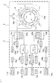
- FIG. 2 is a block diagram of a permanent magnet synchronous motor according to a first embodiment of the present invention, which corresponds to a drive integrated permanent magnet synchronous motor 1 in the electric power steering apparatus 101 shown in FIG. .
- the stator 4 in the motor unit 2 of the permanent magnet type synchronous motor 1 integrated with the driving device includes a stator core 5 formed by laminating magnetic thin plates in the axial direction. Twelve teeth 6 as a plurality of teeth are formed on the inner peripheral portion of the stator core 5 at an angular interval of 30 degrees as a predetermined angle.
- the armature winding 7 is wound around every other teeth of the twelve teeth 6 by concentrated winding.
- the armature winding 7 is composed of two sets of three-phase delta connected or three-phase star connected two independent armature windings, ie, a first armature winding 71 and a second armature winding 72. It is configured.
- the first armature winding 71 includes a first U-phase armature winding 71U, a first V-phase armature winding 71V, and a first W-phase armature winding 71W.
- the U-phase armature winding 71U, the first V-phase armature winding 71V, and the first W-phase armature winding 71W are wound around every third teeth 6, respectively.
- the second armature winding 72 includes a second U-phase armature winding 72U, a second V-phase armature winding 72V, and a second W-phase armature winding 72W.
- the U-phase armature winding 72U, the second V-phase armature winding 72V, and the second W-phase armature winding 72W are wound around every third teeth 6, respectively.
- the first U-phase armature winding 71U and the second U-phase armature winding 72U are wound on teeth on both sides of the teeth 61 with the teeth 61 between which the winding is not wound.
- the V-phase armature winding 71V and the second V-phase armature winding 72V are wound around the teeth 62 on both sides of the tooth 62 on which the winding is not wound, and the first W
- the armature winding 71W and the second W-phase armature winding 72W are wound around the teeth 63 on both sides of the tooth 63 with the winding being not wound.
- the first armature winding 71 and the second armature winding 72 are alternately wound around every other teeth. Since the first armature winding 71 and the second armature winding 72 are alternately wound around every other teeth in this manner, the first armature winding 71 and the second electric motor are Since the magnetic coupling with the child winding 72 is small and mutual inductance is small, even if a short circuit accident occurs in one armature winding and a short circuit current flows, an armature current flowing in the other armature winding There is less negative impact on
- the control device 3 in the drive-integrated permanent magnet synchronous motor 1 includes a first microcomputer 14a, a first inverter 15a, a first filter coil 18a, and a first power supply relay 19a.
- a first torque sensor signal interface 20a, a first vehicle signal interface 21a, and a first drive circuit 22a are provided.
- the first inverter 15a includes, for example, a U-phase upper arm and a U-phase lower arm each having a semiconductor switching element, a V-phase upper arm and a V-phase lower arm each having a semiconductor switching element, and a semiconductor switching element It is comprised by the three-phase bridge circuit (not shown) which consists of the W-phase upper arm and the W-phase lower arm which were equipped.
- the first inverter 15a includes a first filter coil 18a and a first power supply connector 11a connected to a power source that outputs DC power based on the output of a battery mounted on a battery, for example. DC power is supplied via the power supply relay 19a.
- the first microcomputer 14a receives the first steering torque signal from the first torque sensor signal connector 13a via the first torque sensor signal interface 20a by the driver of the vehicle, and the first vehicle signal. A first vehicle signal such as a vehicle speed is input from the connector 12a through the first vehicle signal interface 21a. Further, the first microcomputer 14a receives a first inverter output current signal corresponding to the output current of the first inverter 15a detected by the first current sensor 23a.
- the first microcomputer 14a outputs a target output current to the first inverter 15a based on the input first steering torque signal, the first vehicle signal such as the vehicle speed, the first inverter output current signal, and the like. A value is calculated, and a first command signal based on the calculation result is applied to the first drive circuit 22a.
- the first drive circuit 22a performs PWM (Pulse Width Modulation) control on each semiconductor switching element of the first inverter 15a based on the first command signal supplied from the first microcomputer 14a, and outputs a target current
- the first inverter 15a outputs a three-phase output current feedback-controlled to follow the value.
- the three-phase output current of the first inverter 15a is determined by a first U-phase armature winding 71U, a first V-phase armature winding 71V, and a first V-phase armature winding 71V that constitute a first armature winding of the motor unit 2. It is supplied to the W-phase armature winding 71 W of 1 and causes the stator 4 to generate a first rotating magnetic field.
- the rotor provided with permanent magnets as field poles is given a driving force and rotates based on the rotation of the first rotating magnetic field.
- the first inverter 15a constitutes a first drive device, and includes a first microcomputer 14a, a first filter coil 18a, a first power relay 19a, and a first torque sensor signal interface 20a.
- the first vehicle signal interface 21a and the first drive circuit 22a constitute a first control device.
- a first electric machine comprising an interface 21a, a first drive circuit 22a, a first U-phase armature winding 71U, a first V-phase armature winding 71V, and a first W-phase armature winding 71W.
- the secondary winding constitutes a first system of the permanent magnet synchronous motor 1.
- control device 3 in the drive-integrated permanent magnet synchronous motor 1 includes a second microcomputer 14b, a second inverter 15b, a second filter coil 18b, and a second power supply relay 19b. , A second torque sensor signal interface 20b, a second vehicle signal interface 21b, and a second drive circuit 22b.
- the second inverter 15b includes, for example, a U-phase upper arm and a U-phase lower arm each having a semiconductor switching element, a V-phase upper arm and a V-phase lower arm each having a semiconductor switching element, and a semiconductor switching element
- a second three-phase bridge circuit (not shown) consisting of the provided W-phase upper arm and W-phase lower arm is provided.
- the second inverter 15b is connected to a second power supply connector 11b connected to a power source for outputting DC power based on the output of, for example, an on-board battery comprising a secondary battery, a second filter coil 18b and a second filter coil 18b. DC power is supplied via the power supply relay 19b.
- the second microcomputer 14b receives a second steering torque signal by the driver of the vehicle from the second torque sensor signal connector 13b via the second torque sensor signal interface 20b and a second vehicle signal. A second vehicle signal such as a vehicle speed is input from the connector 12 b via the second vehicle signal interface 21 b. Further, the second microcomputer 14b receives a second inverter output current signal corresponding to the output current of the second inverter 15b detected by the second current sensor 23b.
- the second microcomputer 14b outputs a target output current to the second inverter 15b based on the input second steering torque signal, the second vehicle signal such as the vehicle speed, and the second inverter output current signal. A value is calculated, and a second command signal based on the calculation result is applied to the second drive circuit 22b.
- the second drive circuit 22 b performs PWM control of each semiconductor switching element of the second inverter 15 b based on the second command signal supplied from the second microcomputer 14 b to follow the output target current value.
- the second inverter 15b outputs a feedback-controlled three-phase output current.
- the three-phase output current of the second inverter 15b is generated by a second U-phase armature winding 72U that constitutes the second armature winding of the motor unit 2, a second V-phase armature winding 72V, and a second
- the second W-phase armature winding 72 W is supplied to the second W-phase armature winding 72 W to generate a second rotating magnetic field in the stator 4.
- the rotor provided with permanent magnets as field poles is given a driving force and rotates based on the rotation of the second rotating magnetic field.
- the second inverter 15b constitutes a second drive device, and includes a second microcomputer 14b, a second filter coil 18b, a second power relay 19b, and a second torque sensor signal interface 20b.
- the second vehicle signal interface 21 b and the second drive circuit 22 b constitute a second control device.
- the lines constitute a second system of the permanent magnet synchronous motor 1.
- the first controller and the second controller distribute the amount of current supplied to the first armature winding 71 and the second armature winding 72.
- the ratio may be configured to be unequal.
- Both the first system and the second system described above control the motor unit 2 in the permanent magnet synchronous motor 1 in coordination with other vehicle systems such as brake control and chassis control via vehicle signals.
- the first system and the second system are configured to control the motor unit 2 in synchronization with each other by the communication device 17 via the synchronization signal.
- a second U-phase armature winding 72U constituting a second armature winding in a second system of a permanent magnet type synchronous motor 1 with an integral drive unit, a second V-phase armature winding
- a failure such as a short circuit occurs in any of the wire 72V and the second W-phase armature winding 72W will be described as an example.
- the second microcomputer 14b in the second system detects the failure in the second armature winding 72 and performs the second drive.
- a command is given to the circuit 22b to stop the driving of the second inverter 15b, and the three-phase armature current as a driving current for the second armature winding 72 is set to "0".
- the torque generated in the motor unit 2 by the second system becomes "0"
- the output torque of the entire motor becomes only the torque by the first system and becomes half or less than that in the normal state.
- the steering can be continued without losing the function of the electric power steering device.
- first U-phase armature winding 71U and the second U-phase armature winding 72U are wound on the teeth on both sides of the teeth 61 with the teeth 61 between which the winding is not wound.
- the first V-phase armature winding 71V and the second V-phase armature winding 72V are wound on teeth on both sides of the tooth 62 with the teeth 62 between which the winding is not wound.
- the first W armature winding 71 W and the second W phase armature winding 72 W are wound around the teeth 63 on both sides of the tooth 63 with the winding being not wound.
- the magnetic coupling between the armature winding 71 and the second armature winding 72 is small, and the mutual inductance is small. As a result, even if a short circuit fault occurs in one armature winding and a short circuit current flows, the armature current flowing in the other armature winding is less adversely affected.
- the torque generated by the first system is controlled by stopping the drive of the permanent magnet type synchronous motor by the second system and simultaneously increasing the drive current by the first system to twice that at the normal time.
- the output torque of the entire motor can be made to be the same as that at normal time by compensating for the disappearance of the torque generated by the second system.
- the other system may be configured to perform the driving with a current amount exceeding the normal maximum current at which no failure occurs in one system.
- the first U-phase armature winding 71U and the second U-phase armature winding 72U The first V-phase armature winding 71V and the second V-phase armature winding 72V are wound around the teeth 61 on both sides of the tooth 61 on which the winding is not wound.
- the first W armature winding 71W and the second W-phase armature winding 72W are wound around the teeth 62 on which the winding is not wound, with the teeth 62 interposed therebetween. It is wound on the teeth on both sides of the tooth 63 across the unwound tooth 63. That is, the first armature winding 71 in the first system and the second armature winding 72 in the second system are alternately wound around the teeth 6.
- the heat generation of the stator 4 is distributed to every third teeth of the first system, The temperature of the motor unit 2 does not rise locally, and the time when the electric power steering apparatus can continuously output the assist torque after a failure can be extended, thereby reducing the driver's operation of the steering wheel can do.
- the electric power steering apparatus configured as described above can maintain its function even in the event of failure of the drive-integrated permanent magnet type synchronous motor, so the safety of the vehicle can be maintained. Can be improved.
- FIG. 3 is a block diagram of a permanent magnet synchronous motor according to a second embodiment of the present invention, which is used as a drive integrated permanent magnet synchronous motor 1 of the electric power steering apparatus 101 shown in FIG.
- the difference from the first embodiment is that, in the normal state, the first microcomputer 14a and the second microcomputer 14b of the control device 3 do not control the motor unit 2 in synchronization with each other via a synchronization signal. It is.
- the other configuration is the same as that of the first embodiment.
- the first U-phase armature winding 71U and the second U-phase armature winding 72U are wound around the teeth 61 on both sides of the tooth 61 with the winding not wound.
- the first V-phase armature winding 71V and the second V-phase armature winding 72V are wound around the teeth 62 on both sides of the tooth 62 with the winding not wound.
- the first W armature winding 71W and the second W-phase armature winding 72W are wound around the teeth 63 on both sides of the teeth 63 with the winding being not wound.
- the magnetic coupling between the first armature winding 71 and the second armature winding 72 is small, and the mutual inductance is small.
- the first microcomputer 14a in the first control unit and the second microcomputer 14b in the second control unit are respectively connected to the motor unit 2 without being affected by each other's drive current.
- a common rotor (not shown) can be driven independently by obtaining signals from an angle detection device (not shown) for detecting the rotational position.
- FIG. 4 is an explanatory view of a permanent magnet type synchronous motor according to a second embodiment of the present invention, and an explanatory view for explaining the operation and effect at the time of failure.
- the drive-integrated permanent magnet synchronous motor is controlled by the first system and controlled by the drive-integrated permanent magnet synchronous motor 1 a and the second system.
- An integral type permanent magnet synchronous motor 1b is schematically shown separately, and the drive integral type permanent magnet synchronous motor 1a includes a motor unit 2a and a control device 3a, and the drive integral type The permanent magnet type synchronous motor 1b includes a motor unit 2b and a control device 3b.
- FIG. 4 is an explanatory view of a permanent magnet type synchronous motor according to a second embodiment of the present invention, and an explanatory view for explaining the operation and effect at the time of failure.
- the drive-integrated permanent magnet synchronous motor is controlled by the first system and controlled by the drive-integrated permanent magnet synchronous motor 1 a and the second system.
- the first microcomputer 14a and the second microcomputer 14b of the controller 3 synchronize with each other via the synchronization signal. If the drive current of the failed second system is set to “0”, the stator core 5 is common to the first system and the second system. Although there are two drive unit integrated permanent magnet synchronous motors, one permanent magnet synchronous motor fails and the remaining normal drive unit permanent magnet synchronous motors Thus, the same operation as that for outputting torque to the electric power steering apparatus can be performed.
- the controller integrated permanent magnet type synchronous motor according to the second embodiment of the present invention, it is possible to provide a single drive unit with redundant electric power steering apparatus whose mountability and weight are restricted. This can be realized by a body permanent magnet synchronous motor, which is a great advantage over conventional drive integrated permanent magnet synchronous motors.
- the electric power steering apparatus when starting the vehicle from the time of parking, the vehicle speed is low, and the driver operates the steering wheel largely, so the electric power steering apparatus also outputs a large assist torque.
- the steering wheel when the steering wheel is fully turned to either the left or right, the current value of the three-phase armature winding of the motor section is locked, and the amount of heat generation of the phase where the current flows most increases. In order to suppress the heat generation, the amount of current in the armature winding must be reduced.
- the controller integrated permanent magnet synchronous motor when there is a difference between the temperature rise of the motor unit and the controller in the first system and the second system, By reducing the amount of current of the higher temperature system and increasing the amount of current of the remaining system in reverse, steering becomes possible without reducing the auxiliary torque.
- the ability to individually control the amount of current in the first system and the second system means that the mutual inductance between the first system and the second system is small, and control is performed independently in each system. Because it can be done, its effect is great.
- the first U-phase armature winding 71U and the second U-phase are used.
- the armature winding 72U is wound around the teeth 61 on both sides of the tooth 61 on which the winding is not wound, the first V-phase armature winding 71V and the second V-phase armature
- the winding 72V is wound around the teeth 62 on both sides of the tooth 62 on which the winding is not wound, and the first W armature winding 71W and the second W phase armature winding 72W Is wound around the teeth 63 on both sides of the teeth 63 across which the winding is not wound. That is, the first armature winding in the first system and the second armature winding in the second system are alternately wound around the teeth.
- the heat generation of the stator 4 is distributed to every third teeth of the first system, The temperature of the motor unit 2 does not rise locally, and the time when the electric power steering apparatus can continuously output the assist torque after a failure can be extended, thereby reducing the driver's operation of the steering wheel can do.
- Third Embodiment 5 is a block diagram of a permanent magnet synchronous motor according to a third embodiment of the present invention, which is used as a drive integrated permanent magnet synchronous motor 1 of the electric power steering apparatus 101 shown in FIG.
- the first U-phase armature winding 71U and the first V-phase armature winding 71V are provided on the teeth on both sides of the tooth 61 with the winding 61 not interposed.
- the first V-phase armature winding 71V and the first W-phase armature winding 71W which are wound are wound around the teeth 64 on both sides of the tooth 64 with the winding not wound.
- the first W armature winding 71W and the second U-phase armature winding 72U are wound around the teeth 62 on both sides of the tooth 62 with the winding not wound. .
- the second U-phase armature winding 72U and the second V-phase armature winding 72V are wound around the teeth 65 on both sides of the tooth 65 with the winding being not wound.
- the second V-phase armature winding 72V and the second W-phase armature winding 72W are wound around the teeth 63 on both sides of the tooth 63 with the winding not wound,
- the W-phase armature winding 72W and the first U-phase armature winding 71U are wound around the teeth 66 on both sides of the tooth 66 with the winding being not wound.
- the permanent magnet synchronous motor according to the third embodiment of the present invention has the first armature in the first system in line symmetry with respect to a straight line Y in the radial direction passing through the axial center X of the stator 4.
- a winding 71 and a second armature winding 72 in the second system are arranged.
- the first U-phase armature winding 71U constituting the first armature winding 71 and one semicircular portion partitioned by the straight line Y in the cross section of the stator 4 in the direction orthogonal to the axis line
- the first V-phase armature winding 71V and the first W-phase armature winding 71W are disposed, and in the other semicircular portion separated by a straight line Y in the cross section of the stator 4 in the direction orthogonal to the axis.
- a second U-phase armature winding 72U, a second V-phase armature winding 72V, and a second W-phase armature winding 72W, which constitute the second armature winding 72, are disposed.
- the other configuration is the same as that of the first embodiment.
- Embodiment 3 of the present invention configured as described above, for example, when the temperature rise of the first system is large, the drive current of the first system is reduced, The temperature distribution of the motor unit 2 can be easily averaged by increasing the drive current of the system 2 and, as a result, the time for which the auxiliary torque can be continuously output by the electric power steering device at normal time can be extended. You can reduce the operation of the steering wheel.
- connection 16a of the first system and the connection of the second system It becomes easy to arrange 16b without geometric interference.
- the connection since it is possible to wire one tooth for each phase to each of the first inverter 15a and the second inverter 15b, there is a feature that the connection becomes simple.
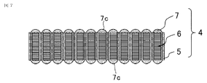
- FIG. 6 is a schematic development view of a permanent magnet synchronous motor according to a fourth embodiment of the present invention.
- the stator 4 includes a stator core 5 configured by laminating magnetic thin plates in the axial direction, a plurality of teeth 6 formed on the inner peripheral portion of the stator core 5, and one.
- the armature winding 7 is concentrated around the teeth 6 of the set.
- the arrangement of the armature winding 7 in the fourth embodiment is the same as that of the third embodiment described above.
- the armature winding 7 is composed of a first armature winding 71 and a second armature winding 72
- the first armature winding 71 is a first U-phase electric machine.
- a secondary winding 71U, a first V-phase armature winding 71V, and a first W-phase armature winding 71W are collectively wound around every other teeth 6.
- the second armature winding 72 is composed of a second U-phase electric machine coil 72U, a second V-phase armature winding 72V, and a second W-phase armature winding 72W, It is concentrated around every other tooth 6 each. Then, as in the case of the third embodiment of FIG.
- the first armature winding and the second armature winding are formed by winding the first armature winding on one semicircular portion of the stator 4. A wire is placed, and a second armature winding is placed in the other half of the stator.
- FIG. 7 is a schematic development view of a permanent magnet type synchronous motor as a comparative example, and shows a case where the stator winding 4 has the armature winding 7 wound around all the teeth 6 of the stator core 5. .
- the axial direction of winding end 7c of armature winding 7 axially projecting from both axial ends of stator core 5 is obtained. Is relatively greater than the axial height of the winding end 7c of the permanent magnet type synchronous motor shown in FIG. This is because the number of turns is increased to be equal to the magnetomotive force in the stator.
- armature winding 7 is wound around every other teeth 6, armature winding 7 is wound.
- Spaces A and B are respectively formed on both sides in the axial direction of the tooth 6 which is not formed.
- the control device 3 is fixed to one end in the axial direction of the stator 4 provided with the space A, and the casing 8 of the metal motor is fixed to the other end in the axial direction of the stator 4 provided with the space B There is.
- the control device 3 comprises at least an aluminum heat sink 9 for dissipating the heat of the inverter, an insulating case 10, a first power connector 11a having a resin case in a first system, and a second system And a first vehicle signal connector 12a having a casing in a first system, and a casing made of a resin in a second system
- a second vehicle signal connector 12b having a first torque sensor signal connector 13a having a resin case in a first system, and a resin case in a second system And a torque sensor signal connector 13b.
- the sensor signal connectors 13 b are each fixed to the axial end face of the insulating housing 10.
- the heat sink 9 is fixed to the stator 4 so as to substantially close one axial end of the stator 4, and the housing 8 of the motor is substantially closed the other axial end of the stator 4. It is fixed to the stator 4.
- the gear box 102 of the electric power steering apparatus 101 shown in FIG. 1 is attached to the housing 8 of the motor.
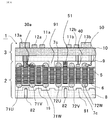
- FIG. 8 is a schematic development view of a permanent magnet synchronous motor according to a fourth embodiment of the present invention, and more specifically shows the permanent magnet synchronous motor according to the fourth embodiment of the present invention.
- the inner end surface of the heat sink 9 is provided with a projecting portion 91 that abuts on the axial end surface of the teeth on which the armature winding is not wound.
- the teeth in which the armature winding is not wound are provided with an iron core 51 which is extended in the axial direction of the stator core and abuts on the inner end surface of the heat sink 9.
- One winding end 7 c of the armature winding 7 is disposed in a space formed at one axial end of the stator core 5 and the inner end surface of the heat sink 9.
- the protrusion 91 and the iron core 51 are parts of components of a permanent magnet synchronous motor.
- a first terminal 30a connecting the first armature winding in the armature winding 7 and the first inverter 15a is disposed.
- a second terminal connecting the second armature winding in the armature winding 7 and the second inverter 15b is also arranged in the same manner, but illustration is omitted.
- an angle detection device for detecting the rotation angle of the rotor of the permanent magnet synchronous motor is The semiconductor magnetic sensor 40 is disposed.
- a temperature sensor 50 for detecting the temperature of the permanent magnet synchronous motor is provided in contact with an insulator surrounding the armature winding 7.
- the first terminal 30a, the second terminal, the semiconductor magnetic sensor 40, and the temperature sensor 50 are part of components of a permanent magnet synchronous motor.
- the first terminal 30a and the second terminal described above are the first power connector 11a and the second power supply provided in the insulating casing 10 of the control device 3 by the conductors passing through the through holes provided in the heat sink 9 It is connected to the connector 11b, respectively.
- the semiconductor magnetic sensor 40 and the temperature sensor 50 are respectively provided with a first microcomputer 14a (not shown) and a second microcomputer 14b (not shown) of the control device 3 by conductors passing through through holes provided in the heat sink 9 respectively. Each connected to).
- the armature winding is not wound on the other axial end of the tooth 6 described above.
- a plurality of ribs 81 for increasing the rigidity of the motor casing 8 and a plurality of screw holes 82 for coupling with the gearbox 102 of the electric power steering apparatus 101 are provided.
- the housing 8 provided with the screw holes 82 is a part of components of the permanent magnet synchronous motor.
- the conventional permanent magnet type motor is disposed above or below the stator.
- the component parts can be arranged in the axial direction of the stator and inside the same outer shape as the stator, and the outer shape and axial length of the drive-integrated permanent magnet synchronous motor can be reduced. Therefore, it is possible to realize a drive-integrated permanent magnet synchronous motor with good mountability with less geometric interference with the vehicle and the electric power steering apparatus.
- the projecting portion 91 of the heat sink 9 made of aluminum for dissipating the heat generation of the inverter of the control device is disposed, and the iron core 51 constituting the projecting portion of the stator core 5 is further By arranging, the heat generated by the armature winding 7 and the heat of the heat sink 9 can be easily released to the stator core 5, and the time for which the steering operation can be continued can be extended.
- the case where the three-phase armature winding is provided has been described.
- polyphase armature windings other than three phases are illustrated. It may be a line.
- the stator showed the example of 12 teeth, it is not limited to 12 teeth.
- the present invention is not limited to the permanent magnet type synchronous motor and the electric power steering apparatus according to the first to fourth embodiments described above, and the first to fourth embodiments can be made without departing from the scope of the present invention. It is possible to appropriately combine the configurations of (1), to partially modify the configurations, or to partially omit the configurations.
- the permanent magnet synchronous motor and the electric power steering device according to the present invention can be used at least in the field of vehicles such as automobiles.
Abstract
第1の電機子巻線(71)と第1の制御装置を含む第1の系統と、第2の電機子巻線(72)と第2の制御装置とを含む第2の系統とにより駆動され、一方の系統が故障したときは、一方の系統による駆動を停止するとともに、他方の系統により駆動を継続するようにした永久磁石式同期モータ及び電動パワーステアリング装置。
Description
この発明は、永久磁石からなる界磁極を有する永久磁石式同期モータ、及びその永久磁石式同期モータを駆動源として用いる電動パワーステアリング装置に関する。
周知のように電動パワーステアリング装置は、例えば駆動装置と一体に構成された駆動装置一体型の永久磁石式同期モータにより発生させた補助トルクにより、自動車等の車両の運転者がステアリングホイールを操作するステアリングトルクを補助する役割を担っている。又、近年では、電動パワーステアリング装置は、自動車の自動運転システムに於いて、車載カメラや車載レーダー等によって検知した路上の障害物を、運転者がステアリングの操作に関与することなく自動的に回避するためのアクチュエータとしての役割を担うようになってきている。従って、このような電動パワーステアリング装置に於いては、ステアリングホイールの操作を補助する補助トルクや、自動運転時に於ける障害物を回避するのに必要なトルクが、突然に消失しないことが重要である。
例えば、電動パワーステアリング装置の駆動源として設けられた永久磁石式同期モータでは、固定子に設けられた電機子巻線が短絡故障した場合に、回転子に設けられた永久磁石からの磁束が回転子の回転に伴って回転することで固定子に設けられた電機子巻線に鎖交し、電機子巻線に於けるインピーダンスの小さな短絡回路に大きな短絡電流が流れることがある。この場合、短絡電流により発生した磁束は、いわゆる反作用磁束として永久磁石式同期モータの回転を阻害する制動トルクを発生させ、電動パワーステアリング装置の動作に不具合を生じさせることがある。
前述のような不具合を避けるために、永久磁石式同期モータの電機子巻線を電気的に独立した2組の電機子巻線により構成すれば、一方の電機子巻線が故障した場合に、その故障した一方の電機子巻線への通電を停止し、正常な他方の電機子巻線により必要なトルクを発生させることができる。
例えば、特許文献1に開示された永久磁石式同期モータは、固定子鉄心の多数のティースのうち1つ置きのティースに固定子巻線が巻回され、この固定子巻線は、スター結線又はデルタ結線された独立した2組の三相電機子巻線を構成しており、一方の三相電機子巻線に短絡故障などが発生しても、他方の三相電機子巻線が正常であることにより、前述の制動トルクを低減させ、同期モータの信頼性を高めることができるように構成されている。
しかしながら、一方の電機子巻線の短絡故障により流れる短絡電流によって発生した反作用磁束は、短絡故障した一方の電機子巻線の短絡回路以外の、正常な他方の電機子巻線にも鎖交するので、正常な電機子巻線に接続されたモータ駆動装置の駆動電圧に影響を与え、意図したモータ制御が困難になる場合がある。何故なら、2組の電機子巻線が同一の固定子鉄心に巻回されているので、2つの電機子巻線に対する磁路が共有されており、相互インダクタンスによって2つの電機子巻線が磁気的に密に結合されているからである。
従って、電動パワーステアリング装置に用いられる2組の電機子巻線を備えた永久磁石式同期モータに於いては、一方の電機子巻線の故障時に正常な他方の電機子巻線によりステアリング操作を継続するために、2組の電機子巻線同士が電気的に互いに独立していることは勿論、磁気的にも互いに密に結合していない構成を備えることが重要な課題となる。
この発明は、2組の電機子巻線を備えた永久磁石式同期モータに於ける前述のような課題を解決するためになされたものであり、2組の電機子巻線のうち一方の電機子巻線を含系統に故障が生じても、他方の電機子巻線を含む系統により所望のトルクを得ることができる永久磁石式同期モータを提供することを目的とする。
又、この発明は、駆動源としての永久磁石式モータの2組の電機子巻線のうち、一方の電機子巻線を含む系統に故障が生じても、他方の電機子巻線を含む系統により所望のトルクを得ることができる電動パワーステアリング装置を提供することを目的とする。
この発明による永久磁石式同期モータは、
内周部に複数のティースを備え、前記内周部に囲まれた空間を有する固定子鉄心と、
前記複数のティースのうちの1つ置きのティースに巻回された電機子巻線と、
前記固定子鉄心の前記空間に挿入され、永久磁石により構成された界磁極を有する回転子と、
を備え、
前記電機子巻線は、互いに独立した第1の電機子巻線と第2の電機子巻線に分離され、
前記第1の電機子巻線は、第1の制御装置に接続され、
前記第2の電機子巻線は、第2の制御装置に接続され、
前記第1の電機子巻線と前記第1の制御装置を含む第1の系統と、前記第2の電機子巻線と前記第2の制御装置とを含む第2の系統と、により駆動され得るように構成された永久磁石式同期モータであって、
前記第1の系統と前記第2の系統のうちの一方の系統が故障したときは、前記一方の系統による前記駆動を停止するとともに、他方の系統により前記駆動を継続するように構成されている、
ことを特徴とする。
又、この発明による電動パワーステアリング装置は、
内周部に複数のティースを備え、前記内周部に囲まれた空間を有する固定子鉄心と、
前記複数のティースのうちの1つ置きのティースに巻回された電機子巻線と、
前記固定子鉄心の前記空間に挿入され、永久磁石により構成された界磁極を有する回転子と、
を備え、
前記電機子巻線は、互いに独立した第1の電機子巻線と第2の電機子巻線に分離され、
前記第1の電機子巻線は、第1の制御装置に接続され、
前記第2の電機子巻線は、第2の制御装置に接続され、
前記第1の電機子巻線と前記第1の制御装置を含む第1の系統と、前記第2の電機子巻線と前記第2の制御装置とを含む第2の系統と、により駆動され得るように構成され、
前記第1の系統と前記第2の系統のうちの一方の系統が故障したときは、前記一方の系統による前記駆動を停止するとともに、他方の系統により前記駆動を継続するように構成された永久磁石式同期モータを備え、
前記永久磁石式同期モータが発生したトルクを車両の操舵に関与させるように構成されている、
ことを特徴とする。
この発明による永久磁石式同期モータによれば、内周部に複数のティースを備え、前記内周部に囲まれた空間を有する固定子鉄心と、前記複数のティースのうちの1つ置きのティースに巻回された電機子巻線と、前記固定子鉄心の前記空間に挿入され、永久磁石により構成された界磁極を有する回転子とを備え、前記電機子巻線は、互いに独立した第1の電機子巻線と第2の電機子巻線に分離され、前記第1の電機子巻線は、第1の制御装置に接続され、前記第2の電機子巻線は、第2の制御装置に接続され、前記第1の電機子巻線と前記第1の制御装置を含む第1の系統と、前記第2の電機子巻線と前記第2の制御装置とを含む第2の系統と、により駆動され得るように構成された永久磁石式同期モータであって、前記第1の系統と前記第2の系統のうちの一方の系統が故障したときは、前記一方の系統による前記駆動を停止するとともに、他方の系統により前記駆動を継続するように構成されているので、一方の系統に故障が生じても他方の系統により所望のトルクを得ることができる永久子爵式同期モータを得ることができる。
又、この発明による電動パワーステアリング装置によれば、内周部に複数のティースを備え、前記内周部に囲まれた空間を有する固定子鉄心と、前記複数のティースのうちの1つ置きのティースに巻回された電機子巻線と、前記固定子鉄心の前記空間に挿入され、永久磁石により構成された界磁極を有する回転子とを備え、前記電機子巻線は、互いに独立した第1の電機子巻線と第2の電機子巻線に分離され、前記第1の電機子巻線は、第1の制御装置に接続され、前記第2の電機子巻線は、第2の制御装置に接続され、前記第1の電機子巻線と前記第1の制御装置を含む第1の系統と、前記第2の電機子巻線と前記第2の制御装置とを含む第2の系統と、により駆動され得るように構成され、前記第1の系統と前記第2の系統のうちの一方の系統が故障したときは、前記一方の系統による前記駆動を停止するとともに、他方の系統により前記駆動を継続するように構成された永久磁石式同期モータを備え、前記永久磁石式同期モータが発生したトルクを車両の操舵に関与させるように構成されているので、一方の系統に故障が生じても他方の系統により所望のトルクを得ることができ車両の操舵をスムーズに継続することが可能な電動パワーステアリング装置を得ることができる。
実施の形態1.
図1はこの発明の実施の形態1による電動パワーステアリング装置の構成図である。図1に於いて、運転者がステアリングホイール(図示せず)を操作すると、運転者が操舵した操舵力がステアリングシャフト(図示せず)を介して、電動パワーステアリング装置101のシャフト105に伝達される。シャフト105に伝達された操舵トルクは、トルクセンサ106により検出されて電気信号に変換され、ケーブル107を通じて駆動装置一体型の永久磁石式同期モータ1のトルクセンサ信号コネクタ13を介して制御装置3に入力される。駆動装置一体型の永久磁石式同期モータ1は、モータ部2と、後述するように駆動装置等を備えた制御装置3と、減速機構を内蔵したギアボックス102とが一体に固定されている。駆動装置一体型の永久磁石式同期モータ1の詳細については後述する。
図1はこの発明の実施の形態1による電動パワーステアリング装置の構成図である。図1に於いて、運転者がステアリングホイール(図示せず)を操作すると、運転者が操舵した操舵力がステアリングシャフト(図示せず)を介して、電動パワーステアリング装置101のシャフト105に伝達される。シャフト105に伝達された操舵トルクは、トルクセンサ106により検出されて電気信号に変換され、ケーブル107を通じて駆動装置一体型の永久磁石式同期モータ1のトルクセンサ信号コネクタ13を介して制御装置3に入力される。駆動装置一体型の永久磁石式同期モータ1は、モータ部2と、後述するように駆動装置等を備えた制御装置3と、減速機構を内蔵したギアボックス102とが一体に固定されている。駆動装置一体型の永久磁石式同期モータ1の詳細については後述する。
又、制御装置3へは、車載ネットワーク(図示せず)の車両速度等の情報が車両信号コネクタ12から入力され、更に、バッテリー等の車載電源(図示せず)からの電力が電源コネクタ11から入力される。駆動装置一体型の永久磁石式同期モータ1の制御装置3は、入力された運転者による操舵トルクや車両速度等の情報から、モータ部2が出力すべきトルクを演算し、制御装置3に設けられた後述するインバータを含む駆動装置を通じてモータ部2の電機子巻線に電流を供給する。
駆動装置一体型の永久磁石式同期モータ1の出力軸としての回転軸は、その軸方向が電動パワーステアリング装置101のハウジング103の軸方向と平行になるように取り付けられている。駆動装置一体型の永久磁石式同期モータ1の出力トルクは、ベルトやボールねじが内蔵されたギアボックス102を介して減速され、ハウジング103内のラック軸を並進運動させる推力に変換され、シャフト105から電動パワーステアリング装置101に入力された運転者の操舵力を補助する。ラック軸の並進運動による推力によりタイロッド104がその軸方向に移動し、車両の操舵輪である前輪(図示せず)を転舵させる。
電動パワーステアリング装置101によって、運転者は小さな操舵力で車両自体の重量が荷重されている前輪を転舵するための大きな操舵力を得ることができ、車両を左右にスムーズに旋回することができる。
尚、自動運転の車両では、車載カメラや車載レーダー等によって検知された障害物を避ける場合や、走行車線を維持又は変更する場合には、電動パワーステアリング装置101アクチュエータとして動作し、運転者のステアリングホイール操作に関わりなく、駆動装置一体型の永久磁石式同期モータ1が車両を操舵すべき必要なトルクを出力する。
以上のように、運転者のステアリング操作の補助を行なう補助トルクや自動運転時の転舵トルクを発生するように構成された電動パワーステアリング装置に於いては、車両の運転中に運転者のステアリング操作の補助を行なう補助トルクや自動運転時の転舵トルクを失わないことが重要である。
そのため、トルクを出力し電動パワーステアリング装置101にそのトルクを伝達する駆動装置一体型の永久磁石式同期モータ1では、故障時に突然にトルクが消失することがないように、インバータを含む駆動装置と、この駆動装置を制御する制御回路と、永久磁石式同期モータとをそれぞれ独立した2つの系統に冗長化し、故障した系統を永久磁石式同期モータの制御及び駆動から切り離し、正常な系統により継続して永久磁石式同期モータから所望のトルクを出力させるように駆動する必要がある。2つの系統に於ける制御装置及び駆動装置は、互いに電気的に独立していれば1つの系統の故障の影響を受けなくて済むが、永久磁石式同期モータは、電気的だけでなく磁気的にも2つの系統が互いに切り離されている必要がある。
正常な系統で継続して永久磁石式同期モータからトルクを出力させるために、電気的だけでなく磁気的にも2つの系統が互いに切り離されている必要がある理由は、磁気的に2つの系統が互いに分離されていない場合には、永久磁石式同期モータに於ける2つの系統間の磁気的な結合である相互インダクタンスが大きい場合、故障した一方の系統への電流供給を停止しても、永久磁石の回転に伴う鎖交磁束により、インピーダンスの小さな一方の系統の電機子巻線の短絡回路に大きな電流が流れ、これを1次電流として相互インダクタンスにより結合した他方の正常な系統の電機子巻線に2次電流が流れ、永久磁石式同期モータに継続してトルクを発生させるための正常な他方の系統の電流を乱してしまうからである。
従って、故障時に継続して出力すべきトルクを確実に発生するためには、2つの系統の磁気的な結合が小さい、即ち相互インダクタンスが小さい2つの系統により、永久磁石式同期モータを冗長化することが要求される。
尚、2つの系統の磁気的な結合が小さい永久磁石式同期モータを得る構成として、1つの駆動装置一体型の永久磁石式同期モータ内にそれぞれの系統に対応した2つの鉄心、即ち2つの固定子を有する構造とすることが考えられるが、この場合は大型で重量が重く、電動パワーステアリング装置への搭載性や自動車の燃費が悪化するため、車両への搭載にはそぐわないことは言うまでもない。
図2は、この発明の実施の形態1による永久磁石式同期モータの構成図であって、図1に示す電動パワーステアリング装置101に於ける駆動装置一体型の永久磁石式同期モータ1に相当する。図2に於いて、駆動装置一体型の永久磁石式同期モータ1のモータ部2に於ける固定子4は、磁性薄板を軸方向に積層して構成された固定子鉄心5を備えている。複数個のティースとしての12個のティース6は、所定の角度としての30度の角度間隔で固定子鉄心5の内周部に形成されている。
電機子巻線7は、12個のティース6のうち一つ置きのティースに集中巻きにより巻回されている。電機子巻線7は、互いに独立した三相デルタ結線若しくは三相スター結線された2組の電機子巻線、即ち、第1の電機子巻線71と第2の電機子巻線72とにより構成されている。
第1の電機子巻線71は、第1のU相電機子巻線71Uと、第1のV相電機子巻線71Vと、第1のW相電機子巻線71Wとからなり、第1のU相電機子巻線71Uと第1のV相電機子巻線71Vと第1のW相電機子巻線71Wは、それぞれ3つ置きのティース6に巻回されている。
第2の電機子巻線72は、第2のU相電機子巻線72Uと、第2のV相電機子巻線72Vと、第2のW相電機子巻線72Wとからなり、第2のU相電機子巻線72Uと第2のV相電機子巻線72Vと第2のW相電機子巻線72Wは、それぞれ3つ置きのティース6に巻回されている。
第1のU相電機子巻線71Uと第2のU相電機子巻線72Uは、巻線が巻回されていないティース61を挟んでそのティース61の両側のティースに巻回され、第1のV相電機子巻線71Vと第2のV相電機子巻線72Vは、巻線が巻回されていないティース62を挟んでそのティース62の両側のティースに巻回され、第1のW電機子巻線71Wと第2のW相電機子巻線72Wは、巻線が巻回されていないティース63を挟んでそのティース63の両側のティースに巻回されている。
そして、第1の電機子巻線71と第2の電機子巻線72は、1つ置きのティースに交互に巻回されている。第1の電機子巻線71と第2の電機子巻線72は、このように1つ置きのティースに交互に巻回されているので、第1の電機子巻線71と第2の電機子巻線72との間の磁気的な結合が小さく、相互インダクタンスが小さいので、一方の電機子巻線に短絡事故が生じて短絡電流が流れても他方の電機子巻線に流れる電機子電流に悪影響を与えることは少なくなる。
駆動装置一体型の永久磁石式同期モータ1に於ける制御装置3は、第1のマイクロコンピュータ14aと、第1のインバータ15aと、第1のフィルタコイル18aと、第1の電源リレー19aと、第1のトルクセンサ信号インターフェイス20aと、第1の車両信号インターフェイス21aと、第1の駆動回路22aとを備えている。第1のインバータ15aは、例えば、それぞれ半導体スイッチング素子を備えたU相上アーム及びU相下アームと、それぞれ半導体スイッチング素子を備えたV相上アーム及びV相下アームと、それぞれ半導体スイッチング素子を備えたW相上アーム及びW相下アームと、からなる三相ブリッジ回路(図示せず)により構成されている。
第1のインバータ15aは、例えば二次電池からなる車載バッテリー等の出力に基づいて直流電力を出力する電力源に接続された第1の電源コネクタ11aから、第1のフィルタコイル18aと第1の電源リレー19aを介して直流電力が供給される。第1のマイクロコンピュータ14aは、第1のトルクセンサ信号コネクタ13aから第1のトルクセンサ信号インターフェイス20aを介して車両の運転者による第1の操舵トルク信号が入力されるとともに、第1の車両信号コネクタ12aから第1の車両信号インターフェイス21aを介して車速等の第1の車両信号が入力される。更に、第1のマイクロコンピュータ14aは、第1の電流センサ23aが検出した第1のインバータ15aの出力電流に対応する第1のインバータ出力電流信号が入力される。
第1のマイクロコンピュータ14aは、入力された前述の第1の操舵トルク信号と車速等の第1の車両信号と第1のインバータ出力電流信号等に基づいて、第1のインバータ15aに対する目標出力電流値を演算し、その演算結果に基づく第1の指令信号を第1の駆動回路22aに与える。第1の駆動回路22aは、第1のマイクロコンピュータ14aから与えられた第1の指令信号に基づいて、第1のインバータ15aの各半導体スイッチング素子をPWM(Pulse Width Modulation)制御し、出力目標電流値に追随するようにフィードバック制御された三相出力電流を第1のインバータ15aから出力させる。
第1のインバータ15aの三相出力電流は、モータ部2の第1の電機子巻線を構成する第1のU相電機子巻線71U、第1のV相電機子巻線71V、及び第1のW相電機子巻線71Wに供給され、固定子4に第1の回転磁界を発生させる。永久磁石を界磁極として備えた回転子は、第1の回転磁界の回転に基づいて駆動力が付与されて回転する。
第1のインバータ15aは、第1の駆動装置を構成し、第1のマイクロコンピュータ14aと、第1のフィルタコイル18aと、第1の電源リレー19aと、第1のトルクセンサ信号インターフェイス20aと、第1の車両信号インターフェイス21aと、第1の駆動回路22aは、第1の制御装置を構成する。
更に、前述の第1のマイクロコンピュータ14aと、第1のインバータ15aと、第1のフィルタコイル18aと、第1の電源リレー19aと、第1のトルクセンサ信号インターフェイス20aと、第1の車両信号インターフェイス21aと、第1の駆動回路22aと、第1のU相電機子巻線71Uと第1のV相電機子巻線71Vと第1のW相電機子巻線71Wからなる第1の電機子巻線は、永久磁石式同期モータ1の第1の系統を構成する。
又、駆動装置一体型の永久磁石式同期モータ1に於ける制御装置3は、第2のマイクロコンピュータ14bと、第2のインバータ15bと、第2のフィルタコイル18bと、第2の電源リレー19bと、第2のトルクセンサ信号インターフェイス20bと、第2の車両信号インターフェイス21bと、第2の駆動回路22bとを備えている。第2のインバータ15bは、例えば、それぞれ半導体スイッチング素子を備えたU相上アーム及びU相下アームと、それぞれ半導体スイッチング素子を備えたV相上アーム及びV相下アームと、それぞれ半導体スイッチング素子を備えたW相上アーム及びW相下アームと、からなる第2の三相ブリッジ回路(図示せず)により構成されている。
第2のインバータ15bは、例えば二次電池からなる車載バッテリ等の出力に基づいて直流電力を出力する電力源に接続された第2の電源コネクタ11bから、第2のフィルタコイル18bと第2の電源リレー19bを介して直流電力が供給される。第2のマイクロコンピュータ14bは、第2のトルクセンサ信号コネクタ13bから第2のトルクセンサ信号インターフェイス20bを介して車両の運転者による第2の操舵トルク信号が入力されるとともに、第2の車両信号コネクタ12bから第2の車両信号インターフェイス21bを介して車速等の第2の車両信号が入力される。更に、第2のマイクロコンピュータ14bは、第2の電流センサ23bが検出した第2のインバータ15bの出力電流に対応する第2のインバータ出力電流信号が入力される。
第2のマイクロコンピュータ14bは、入力された前述の第2の操舵トルク信号と車速等の第2の車両信号と第2のインバータ出力電流信号等に基づいて、第2のインバータ15bに対する目標出力電流値を演算し、その演算結果に基づく第2の指令信号を第2の駆動回路22bに与える。第2の駆動回路22bは、第2のマイクロコンピュータ14bから与えられた第2の指令信号に基づいて、第2のインバータ15bの各半導体スイッチング素子をPWM制御し、出力目標電流値に追随するようにフィードバック制御された三相出力電流を第2のインバータ15bから出力させる。
第2のインバータ15bの三相出力電流は、モータ部2の第2の電機子巻線を構成する第2のU相電機子巻線72U、第2のV相電機子巻線72V、及び第2のW相電機子巻線72Wに供給され、固定子4に第2の回転磁界を発生させる。永久磁石を界磁極として備えた回転子は、第2の回転磁界の回転に基づいて駆動力が付与されて回転する。
第2のインバータ15bは、第2の駆動装置を構成し、第2のマイクロコンピュータ14bと、第2のフィルタコイル18bと、第2の電源リレー19bと、第2のトルクセンサ信号インターフェイス20bと、第2の車両信号インターフェイス21bと、第2の駆動回路22bは、第2の制御装置を構成する。
前述の第2のマイクロコンピュータ14bと、第2のインバータ15bと、第2のフィルタコイル18bと、第2の電源リレー19bと、第2のトルクセンサ信号インターフェイス20bと、第2の車両信号インターフェイス21bと、第2の駆動回路22bと、第2のU相電機子巻線72Uと第2のV相電機子巻線72Vと第2のW相電機子巻線72Wからなる第2の電機子巻線は、永久磁石式同期モータ1の第2の系統を構成する。
故障が発生していない通常時に於いて、第1の制御装置と前記第2の制御装置は、第1の電機子巻線71と前記第2の電機子巻線72に供給する電流量の配分比率を不等分とするように構成されていてもよい。
前述の第1の系統と第2の系統は、共に車両信号を介して、ブレーキ制御やシャーシ制御等の他の車両システムと協調して、永久磁石式同期モータ1に於けるモータ部2を制御するよう構成されているほか、第1の系統と第2の系統は、通信装置17により同期信号を介して互いに同期してモータ部2を制御するように構成されている。
ここで、駆動装置一体型の永久磁石式同期モータ1の故障時の動作について説明する。例えば、駆動装置一体型の永久磁石式同期モータ1の第2の系統に於ける第2の電機子巻線を構成する第2のU相電機子巻線72U、第2のV相電機子巻線72V、及び第2のW相電機子巻線72Wの何れかに短絡などの故障が生じた場合を例として説明する。
第2の電機子巻線72に短絡などの故障が生じると、第2の系統に於ける第2のマイクロコンピュータ14bは、第2の電機子巻線72の故障を検知して第2の駆動回路22bに指令を与えて第2のインバータ15bの駆動を停止させ、第2の電機子巻線72に対する駆動電流としての三相電機子電流を「0」とする。これにより、第2の系統によりモータ部2に発生していたトルクは「0」となり、モータ全体の出力トルクは第1の系統によるトルクのみとなり正常時の2分の1以下となるが、完全に電動パワーステアリング装置の機能を失うことはなく、転舵を継続することができる。
更に、第1のU相電機子巻線71Uと第2のU相電機子巻線72Uは、巻線が巻回されていないティース61を挟んでそのティース61の両側のティースに巻回され、第1のV相電機子巻線71Vと第2のV相電機子巻線72Vは、巻線が巻回されていないティース62を挟んでそのティース62の両側のティースに巻回され、第1のW電機子巻線71Wと第2のW相電機子巻線72Wは、巻線が巻回されていないティース63を挟んでそのティース63の両側のティースに巻回されているので、第1の電機子巻線71と第2の電機子巻線72との間の磁気的な結合が小さく相互インダクタンスが小さくなる。その結果、一方の電機子巻線に短絡事故が生じて短絡電流が流れても他方の電機子巻線に流れる電機子電流に悪影響を与えることは少なくなる。
又、第2の系統による永久磁石式同期モータの駆動を停止すると同時に、第1の系統による駆動電流を正常時の2倍に増加させる制御を行うことにより、第1の系統により発生されるトルクも2倍となり、第2の系統により発生していたトルクの消滅を補ってモータ全体の出力トルクを正常時と変わらないものとすることもできる。
尚、一方の系統が故障したときは、他方の系統は、一方の系統に故障が生じていない通常時の最大電流を超えた電流量により前記駆動を行うように構成されていてもよい。
更に、この発明の実施の形態1による駆動装置一体型の永久磁石式同期モータによれば、前述のように、第1のU相電機子巻線71Uと第2のU相電機子巻線72Uは、巻線が巻回されていないティース61を挟んでそのティース61の両側のティースに巻回され、第1のV相電機子巻線71Vと第2のV相電機子巻線72Vは、巻線が巻回されていないティース62を挟んでそのティース62の両側のティースに巻回され、第1のW電機子巻線71Wと第2のW相電機子巻線72Wは、巻線が巻回されていないティース63を挟んでそのティース63の両側のティースに巻回されている。つまり、第1の系統に於ける第1の電機子巻線71と第2の系統に於ける第2の電機子巻線72が、交互にティース6に巻回されている。
従って、例えば、第2の系統の故障で第2の系統の駆動電流を「0」とした場合に、固定子4の発熱は、第1の系統の3つ置きのティースに分散されるので、モータ部2の温度が局所的に上昇することがなく、故障後に電動パワーステアリング装置が補助トルクを継続して出力することができる時間を長くすることができ、運転者のステアリングホイールの操作を軽減することができる。
以上のように構成されたこの実施の形態1による電動パワーステアリング装置は、駆動装置一体型の永久磁石式同期モータの故障時に於いても、その機能を維持することができるため、車両の安全性を向上させることができる。
実施の形態2.
図3は、この発明の実施の形態2による永久磁石式同期モータの構成図であって、図1に示す電動パワーステアリング装置101の駆動装置一体型の永久磁石式同期モータ1として用いられる。実施の形態1と異なる点は、正常時において、制御装置3の第1のマイクロコンピュータ14aと第2のマイクロコンピュータ14bとが同期信号を介して互いに同期してモータ部2を制御していないことである。その他の構成は実施の形態1と同様である。
図3は、この発明の実施の形態2による永久磁石式同期モータの構成図であって、図1に示す電動パワーステアリング装置101の駆動装置一体型の永久磁石式同期モータ1として用いられる。実施の形態1と異なる点は、正常時において、制御装置3の第1のマイクロコンピュータ14aと第2のマイクロコンピュータ14bとが同期信号を介して互いに同期してモータ部2を制御していないことである。その他の構成は実施の形態1と同様である。
前述のように、第1のU相電機子巻線71Uと第2のU相電機子巻線72Uは、巻線が巻回されていないティース61を挟んでそのティース61の両側のティースに巻回され、第1のV相電機子巻線71Vと第2のV相電機子巻線72Vは、巻線が巻回されていないティース62を挟んでそのティース62の両側のティースに巻回され、第1のW電機子巻線71Wと第2のW相電機子巻線72Wは、巻線が巻回されていないティース63を挟んでそのティース63の両側のティースに巻回されているので、第1の電機子巻線71と第2の電機子巻線72との間の磁気的な結合が小さく相互インダクタンスが小さくなる。
従って、互いの駆動電流の影響を受けずに、第1の制御装置に於ける第1のマイクロコンピュータ14aと、第2の制御装置に於ける第2のマイクロコンピュータ14bは、それぞれモータ部2の回転位置を検出する角度検出装置(図示せず)の信号を得て、共通する1つのロータ(図示せず)を独立して駆動することができる。
図4は、この発明の実施の形態2による永久磁石式同期モータの説明図であって、故障時の動作と効果を説明する説明図である。図4では、説明の便宜上、駆動装置一体型の永久磁石式同期モータを、第1の系統により制御される駆動装置一体型の永久磁石式同期モータ1aと第2の系統により制御される駆動装置一体型の永久磁石式同期モータ1bに模式的に分離して図示しており、駆動装置一体型の永久磁石式同期モータ1aは、モータ部2aと制御装置3aとを備え、駆動装置一体型の永久磁石式同期モータ1bは、モータ部2bと制御装置3bを備える。例えば、図4に示すように、第2の系統の電機子巻線71を構成する第2のU相電機子巻線72Uと第2のV相電機子巻線72Vとの間に短絡事故が生じた場合、第2のU相電機子巻線72Uと第2のV相電機子巻線72Vに短絡電流が流れ、その短絡電流に基づく磁束Φが流れる。しかしこの磁束Φは、正常な第1の電機子巻線71を構成する第1のU相電機子巻線71Uのほか、第1のV相電機子巻線71V及び第2のW相電機子巻線72Wが巻回されているティースを実質的に通過することはない。
従って、第2の系統に於ける第2の電機子巻線72に短絡等の事故が発生しても、正常な第1の系統に於ける第1の電機子巻線71の制御に実質的に悪影響を与えることはない。同様に、第1の系統に於ける第1の電機子巻線71に短絡等の事故が発生した場合でも、正常な第2の系統に於ける第2の電機子巻線72の制御に実質的に悪影響を与えることはない。
更に、この発明の実施の形態2による制御装置一体型の永久磁石式同期モータによれば、制御装置3の第1のマイクロコンピュータ14aと第2のマイクロコンピュータ14bとが同期信号を介して互いに同期してモータ部2を制御していないこともあり、故障した第2の系統の駆動電流を「0」とした場合は、固定子鉄心5が第1の系統と第2の系統で共通しているにも関わらず、あたかも2つの駆動装置一体型の永久磁石式同期モータが存在していてそのうち1つの永久磁石式同期モータが故障し、残りの正常な駆動装置一体型の永久磁石式同期モータにより電動パワーステアリング装置にトルクを出力するのと同様の動作を行うことができる。
以上述べたように、この発明の実施の形態2による制御装置一体型の永久磁石式同期モータによれば、搭載性や重量に制約がある電動パワーステアリング装置の冗長化を、1つの駆動装置一体型の永久磁石式同期モータで実現できるので従来の駆動装置一体型の永久磁石式同期モータにはない大きな利点である。
又、例えば、車両を駐車時から発進する場合、車両速度が遅く、且つ、運転者は大きくステアリングホイールを操作するため、電動パワーステアリング装置も大きな補助トルクを出力する。このとき、ステアリングホイールを左右どちらかにいっぱいまで切ると、モータ部の三相の電機子巻線の電流値が固定したロック状態となり、電流が一番多く流れる相の発熱量が大きくなるので、その発熱を抑えるために電機子巻線の電流量を絞らなければならない。
しかし、この発明の実施の形態2による制御装置一体型の永久磁石式同期モータによれば、第1の系統と第2の系統でモータ部や制御装置の温度上昇に差がある場合には、より温度が高い系統の電流量を減らし、残りの系統の電流量を逆に増加させることで、補助トルクを減らさずに転舵可能となる。このように、第1の系統と第2の系統とで電流量を個別に制御できるのは、第1の系統と第2の系統との間の相互インダクタンスが小さく、各系統で独立して制御することができるからであり、その効果は大きい。
尚、この発明の実施の形態2による制御装置一体型の永久磁石式同期モータによれば、実施の形態1の場合と同様に、第1のU相電機子巻線71Uと第2のU相電機子巻線72Uは、巻線が巻回されていないティース61を挟んでそのティース61の両側のティースに巻回され、第1のV相電機子巻線71Vと第2のV相電機子巻線72Vは、巻線が巻回されていないティース62を挟んでそのティース62の両側のティースに巻回され、第1のW電機子巻線71Wと第2のW相電機子巻線72Wは、巻線が巻回されていないティース63を挟んでそのティース63の両側のティースに巻回されている。つまり、第1の系統に於ける第1の電機子巻線と第2の系統に於ける第2の電機子巻線が、交互にティースに巻回されている。
従って、例えば、第2の系統の故障で第2の系統の駆動電流を「0」とした場合に、固定子4の発熱は、第1の系統の3つ置きのティースに分散されるので、モータ部2の温度が局所的に上昇することがなく、故障後に電動パワーステアリング装置が補助トルクを継続して出力することができる時間を長くすることができ、運転者のステアリングホイールの操作を軽減することができる。
実施の形態3.
図5は、この発明の実施の形態3による永久磁石式同期モータの構成図であって、図1に示す電動パワーステアリング装置101の駆動装置一体型の永久磁石式同期モータ1として用いられる。図5に於いて、第1のU相電機子巻線71Uと第1のV相電機子巻線71Vは、巻線が巻回されていないティース61を挟んでそのティース61の両側のティースに巻回され、第1のV相電機子巻線71Vと第1のW相電機子巻線71Wは、巻線が巻回されていないティース64を挟んでそのティース64の両側のティースに巻回され、第1のW電機子巻線71Wと第2のU相電機子巻線72Uは、巻線が巻回されていないティース62を挟んでそのティース62の両側のティースに巻回されている。
図5は、この発明の実施の形態3による永久磁石式同期モータの構成図であって、図1に示す電動パワーステアリング装置101の駆動装置一体型の永久磁石式同期モータ1として用いられる。図5に於いて、第1のU相電機子巻線71Uと第1のV相電機子巻線71Vは、巻線が巻回されていないティース61を挟んでそのティース61の両側のティースに巻回され、第1のV相電機子巻線71Vと第1のW相電機子巻線71Wは、巻線が巻回されていないティース64を挟んでそのティース64の両側のティースに巻回され、第1のW電機子巻線71Wと第2のU相電機子巻線72Uは、巻線が巻回されていないティース62を挟んでそのティース62の両側のティースに巻回されている。
更に、第2のU相電機子巻線72Uと第2のV相電機子巻線72Vは、巻線が巻回されていないティース65を挟んでそのティース65の両側のティースに巻回され、第2のV相電機子巻線72Vと第2のW相電機子巻線72Wは、巻線が巻回されていないティース63を挟んでそのティース63の両側のティースに巻回され、第2のW相電機子巻線72Wと第1のU相電機子巻線71Uは、巻線が巻回されていないティース66を挟んでそのティース66の両側のティースに巻回されている。
即ち、この発明の実施の形態3による永久磁石式同期モータは、固定子4の軸心Xを通る半径方向の直線Yに対して線対称に、第1の系統に於ける第1の電機子巻線71と第2の系統に於ける第2の電機子巻線72が配置されている。つまり、軸線と直交する方向の固定子4の断面に於ける直線Yにより仕切られる一方の半円部に、第1の電機子巻線71を構成する第1のU相電機子巻線71Uと第1のV相電機子巻線71Vと第1のW相電機子巻線71Wが配置され、軸線と直交する方向の固定子4の断面に於ける直線Yにより仕切られる他方の半円部に、第2の電機子巻線72を構成する第2のU相電機子巻線72Uと第2のV相電機子巻線72Vと第2のW相電機子巻線72Wが配置されている。その他の構成は、実施の形態1と同様である。
以上のように構成されたこの発明の実施の形態3による永久磁石式同期モータに於いて、例えば、第1の系統の温度上昇が大きい場合に、第1の系統の駆動電流を小さくし、第2の系統の駆動電流を増やすことで、モータ部2の温度分布を平均化しやすくなり、その結果、正常時の電動パワーステアリング装置で補助トルクを継続出力できる時間を長くすることができ、運転者のステアリングホイール操作を軽減できる。
又、第1の電機子巻線71と第2の電機子巻線72が固定子4に対して線対称に半分に分かれているので、第1の系統の結線16aと第2の系統の結線16bを幾何学的な干渉なく配置し易くなる。特に集中巻モータでは、第1のインバータ15aと第2のインバータ15bにそれぞれ各相毎に1つのティースに配線することができるので、結線が簡単となる特徴がある。
実施の形態4.
図6は、この発明の実施の形態4による永久磁石式同期モータの概略展開図である。図6に於いて、固定子4は、磁性薄板が軸方向に積層されて構成された固定子鉄心5と、固定子鉄心5の内周部に形成された複数個のティース6と、1つ置きのティース6に集中巻きされた電機子巻線7とを備えている。実施の形態4に於ける電機子巻線7の配置は、前述の実施の3の場合と同様である。
図6は、この発明の実施の形態4による永久磁石式同期モータの概略展開図である。図6に於いて、固定子4は、磁性薄板が軸方向に積層されて構成された固定子鉄心5と、固定子鉄心5の内周部に形成された複数個のティース6と、1つ置きのティース6に集中巻きされた電機子巻線7とを備えている。実施の形態4に於ける電機子巻線7の配置は、前述の実施の3の場合と同様である。
即ち、電機子巻線7は、第1の電機子巻線71と第2の電機子巻線72とから構成されており、第1の電機子巻線71は、第1のU相電機機子巻線71Uと、第1のV相電機子巻線71Vと、第1のW相電機子巻線71Wとから構成され、それぞれ1つ置きのティース6に集中巻きされている。第2の電機子巻線72は、第2のU相電機機子巻線72Uと、第2のV相電機子巻線72Vと、第2のW相電機子巻線72Wとから構成され、それぞれ1つ置きのティース6に集中巻きされている。そして、第1の電機子巻線と第2の電機子巻線は、前述の図5の実施の形態3の場合と同様に、固定子4の一方の半円部に第1の電機子巻線が配置され、固定子の他方の半円部に第2の電機子巻線が配置されている。
図7は、比較例としての永久磁石式同期モータの概略展開図であって、固定子4は、固定子鉄心5の全てのティース6に電機子巻線7を巻回した場合を示している。図6に示すこの発明の実施の形態4による永久磁石式同期モータは、固定子鉄心5の軸方向の両端部からそれぞれ軸方向に突出する電機子巻線7の巻線端部7cの軸方向の高さが、比較例の図7に示す永久磁石式同期モータの巻線端部7cの軸方向の高さより相対的に大きくなっているのは、固定子4に於ける起磁力を従来の固定子に於ける起磁力と同等にするために巻数が増加しているためである。
図6に於いて、この発明の実施の形態4による永久磁石式同期モータは、電機子巻線7が1つ置きのティース6に巻回されているので、電機子巻線7が巻回されていないティース6の軸方向の両側にそれぞれ空間A、Bが形成されている。空間Aを備えた固定子4の軸方向の一端には制御装置3が固定され、空間Bを備えた固定子4の軸方向の他端には金属製のモータの筐体8が固定されている。
制御装置3は、少なくともインバータの発熱を逃がすアルミニウム製のヒートシンク9と、絶縁筐体10と、第1の系統に於ける樹脂製の筐体を有する第1の電源コネクタ11aと、第2の系統に於ける樹脂製の筐体を有する第2の電源コネクタ11bと、第1の系統に於ける筐体を有する第1の車両信号コネクタ12aと、第2の系統に於ける樹脂製の筐体を有する第2の車両信号コネクタ12bと、第1の系統に於ける樹脂製の筐体を有する第1のトルクセンサ信号コネクタ13aと、第2の系統に於ける樹脂製の筐体を有する第2のトルクセンサ信号コネクタ13bとを備えている。
前述の第1の電源コネクタ11aと、第2の電源コネクタ11bと、第1の車両信号コネクタ12aと、第2の車両信号コネクタ12bと、第1のトルクセンサ信号コネクタ13aと、第2のトルクセンサ信号コネクタ13bは、それぞれ絶縁筐体10の軸方向端面に固定されている。
ヒートシンク9は、固定子4の軸方向の一端を実質的に閉塞するように固定子4に固定され、モータの筐体8は固定子4の軸方向の他端を実質的に閉塞するように固定子4に固定されている。モータの筐体8には、図1に示す電動パワーステアリング装置101のギアボックス102が装着される。
図8は、この発明の実施の形態4による永久磁石式同期モータの模式展開図であって、この発明の実施の形態4による永久磁石式同期モータを、より具体的に示している。図8に於いて、ヒートシンク9の内端面には、電機子巻線が巻回されていないティースの軸方向の端面に当接する突出部91が設けられている。又、電機子巻線が巻回されていないティースは、固定子鉄心の軸方向に延長されてヒートシンク9の内端面に当接する鉄心51を備えている。電機子巻線7の一方の巻線端部7cは、固定子鉄心5の軸方向の一端とヒートシンク9の内端面に形成される空間に配置されている。突出部91と鉄心51は、永久磁石式同期モータの構成部品の一部である。
前述の図6に示す空間Aには、電機子巻線7に於ける第1の電機子巻線と第1のインバータ15aとを接続する第1のターミナル30aが配置されている。尚、電機子巻線7に於ける第2の電機子巻線と第2のインバータ15bとを接続する第2のターミナルも同様に配置されているが図示を省略している。電機子巻線が巻回されていないティース6の軸方向の一端とヒートシンク9の内端面との間の空間には、永久磁石式同期モータの回転子の回転角度を検出する角度検出装置に於ける半導体磁気センサ40が配置されている。永久磁石式同期モータの温度を検出する温度センサ50は、電機子巻線7を包囲している絶縁物に接して設けられている。第1のターミナル30aと、第2のターミナルと、半導体磁気センサ40と、温度センサ50は、永久磁石式同期モータの構成部品の一部である。
前述の第1のターミナル30a及び第2のターミナルは、ヒートシンク9に設けられた貫通穴を貫通する導体により制御装置3の絶縁筐体10に設けられた第1の電源コネクタ11a、第2の電源コネクタ11bにそれぞれ接続されている。半導体磁気センサ40及び温度センサ50は、それぞれヒートシンク9に設けられた貫通穴を貫通する導体により制御装置3の第1のマイクロコンピュータ14a(図示せず)及び第2のマイクロコンピュータ14b(図示せず)にそれぞれ接続されている。
固定子4の軸方向の他端に固定された金属製のモータの筐体8の内壁面には、電機子巻線が巻回されていないティース6の軸方向の他端に存在する前述の空間Bに対応して、モータの筐体8の剛性を高くするための複数のリブ81、及び電動パワーステアリング装置101のギアボックス102と結合するための複数のネジ穴82が設けられている。ネジ穴82が設けられた筐体8は、永久磁石式同期モータの構成部品の一部である。
以上述べたように、この発明の実施の形態4による永久磁石式同期モータによれば、前述のように構成されているので、従来の永久磁石式モータでは固定子の上方や下方に配置されていた構成部品を、固定子の軸方向で且つ固定子と同じ外形の内側に配置することができ、駆動装置一体型の永久磁石式同期モータの外形及び軸方向長さを小さくすることができる。従って、車両や電動パワーステアリング装置との幾何学的な干渉の少ない搭載性のよい駆動装置一体型の永久磁石式同期モータを実現することができる。
又、例えば、前述の図6に示す空間Aには、制御装置のインバータの発熱を逃がすアルミニウム製のヒートシンク9の突出部91を配置し、更に固定子鉄心5の突出部を構成する鉄心51を配置することで、電機子巻線7での発熱やヒートシンク9の熱を固定子鉄心5に逃がしやすくし、ステアリング操作を継続できる時間を長くすることができる。
尚、以上述べたこの発明の実施の形態1から4による永久磁石式同期モータによれば、三相の電機子巻線を備えた場合を示したが、三相以外の多相の電機子巻線であってもよい。又、固定子は、12個のティースの例を示したが、12個のティースに限定されるものではない。
尚、この発明は前述の実施の形態1から4による永久磁石式同期モータ及び電動パワーステアリング装置に限定されるものではなく、この発明の趣旨を逸脱しない範囲に於いて、実施の形態1から4の構成を適宜組み合わせたり、その構成に一部変形を加えたり、構成を一部省略することが可能である。
この発明による永久磁石式同期モータ及び電動パワーステアリング装置は、少なくとも自動車等の車両の分野に利用することができる。
1、1a、1b 駆動装置一体型の永久磁石式同期モータ、2、2a、2b モータ部、3、3a、3b 制御装置、4 固定子、5 固定子鉄心、51 突出部を構成する鉄心、6、61、62、63、64 ティース、7 電機子巻線、71U 第1のU相電機子巻線、71V 第1のV相電機子巻線、71W 第1のW相電機子巻線、72U 第2のU相電機子巻線、72V 第2のV相電機子巻線、72W 第2のW相電機子巻線、8 筐体、81 リブ、82 ネジ穴、9 ヒートシンク、91 突出部、10 絶縁筐体、11、11a、11b 電源コネクタ、12 車両信号コネクタ、12a 第1の車両信号コネクタ、12b 第2の車両信号コネクタ、13 トルクセンサ信号コネクタ、13a 第1のトルクセンサ信号コネクタ、13b 第2の車両信号コネクタ、14a 第1のマイクロコンピュータ、14b 第2のマイクロコンピュータ、15a 第1のインバータ、15b 第2のインバータ、16a 第1の系統の結線、16b 第2の系統の結線、17 通信装置、18a 第1のフィルタコイル、18b 第2のフィルタコイル、19a 第1の電源リレー、19b 第2の電源リレー、20a 第1のトルクセンサ信号インターフェイス、20b 第2のトルクセンサ信号インターフェイス、21a 第1の車両信号インターフェイス、21b 第2の車両信号インターフェイス、22a 第1の駆動回路、22b 第2の駆動回路、23a 第1の電流センサ、23b 第2の電流センサ、101 電動パワーステアリング装置、102 ギアボックス、103 ハウジング、104 タイロッド、105 シャフト、106 トルクセンサ、107 ケーブル
-
-
Claims (15)
- 内周部に複数のティースを備え、前記内周部に囲まれた空間を有する固定子鉄心と、
前記複数のティースのうちの1つ置きのティースに巻回された電機子巻線と、
前記固定子鉄心の前記空間に挿入され、永久磁石により構成された界磁極を有する回転子と、
を備え、
前記電機子巻線は、互いに独立した第1の電機子巻線と第2の電機子巻線に分離され、
前記第1の電機子巻線は、第1の制御装置に接続され、
前記第2の電機子巻線は、第2の制御装置に接続され、
前記第1の電機子巻線と前記第1の制御装置を含む第1の系統と、前記第2の電機子巻線と前記第2の制御装置とを含む第2の系統と、により駆動され得るように構成された永久磁石式同期モータであって、
前記第1の系統と前記第2の系統のうちの一方の系統が故障したときは、前記一方の系統による前記駆動を停止するとともに、他方の系統により前記駆動を継続するように構成されている、
ことを特徴とする永久磁石式同期モータ。 - 前記故障が発生していない通常時に於いて、
前記第1の制御装置と前記第2の制御装置は、互いに同期して動作するように構成されている、
ことを特徴とする請求項1に記載の永久磁石式同期モータ。 - 前記故障が発生していない通常時に於いて、
前記第1の制御装置と前記第2の制御装置は、互いに同期することなくそれぞれ独立して動作するように構成されている、
ことを特徴とする請求項1に記載の永久磁石式同期モータ。 - 前記一方の系統が故障したときは、
前記他方の系統は、前記一方の系統に故障が生じていない通常時の最大電流を超えた電流量により前記駆動を行うように構成されている、
ことを特徴とする請求項1から請求項3のうちの何れか一項に記載の永久磁石式同期モータ。 - 前記故障が発生していない通常時に於いて、
前記第1の制御装置と前記第2の制御装置は、前記第1の電機子巻線と前記第2の電機子巻線に供給する電流量の配分比率を不等分とするように構成されている、
ことを特徴とする請求項1に記載の永久磁石式同期モータ。 - 前記第1の電機子巻線と前記第2の電機子巻線は、前記1つ置きのティースに交互に巻回されている、
ことを特徴とする請求項1から請求項5のうちのいずれか一項に記載の永久磁石式同期モータ。 - 前記第1の電機子巻線は、第1の巻線ブロックとして前記ティースに巻回され、
前記第2の電機子巻線は、第2の巻線ブロックとして前記ティースに巻回され、
前記第1の巻線ブロックと前記第2の巻線ブロックは、前記固定子鉄心に対称に配置されている、
ことを特徴とする請求項1から請求項5のうちのいずれか一項に記載の永久磁石式同期モータ。 - 前記電機子巻線が巻回されていないティースの軸方向の少なくとも一方の端部に対応して、永久磁石式同期モータの構成部品が配置されている、
ことを特徴とする請求項1から請求項7のうちのいずれか一項に記載の永久磁石式同期モータ。 - 前記構成部品は、前記第1の制御装置と前記第1の電機子巻線とを接続する第1のターミナルと、前記第2の制御装置と前記第2の電機子巻線とを接続する第2のターミナルと、のうちの少なくとも一方のターミナルである、
ことを特徴とする請求項8に記載の永久磁石式同期モータ。 - 前記第1の制御装置と前記第2の制御装置とを冷却するヒートシンクを備え、
前構成部品は、前記ヒートシンクに設けられた突出部である、
ことを特徴とする請求項8に記載の永久磁石式同期モータ。 - 前記構成部品は、前記電機子巻線が巻回されていないティースから前記固定子鉄心の軸方向に延長された鉄心である、
ことを特徴とする請求項8に記載の駆動装置一体型の永久磁石式同期モータ。 - 前記構成部品は、永久磁石式同期モータを他の構成部材に固定するための取付け部である、
ことを特徴とする請求項8に記載の永久磁石式同期モータ。 - 前記構成部品は、前記回転子の回転角度を検出する角度検出装置に於ける磁気センサである、
ことを特徴とする請求項8に記載の駆動装置一体型の永久磁石式同期モータ。 - 前記構成部品は、永久磁石式同期モータの温度を検出する温度センサである、
ことを特徴とする請求項8に記載の永久磁石式同期モータ。 - 請求項1から請求項14のうちのいずれか一項に記載の永久磁石式同期モータを備え、
前記永久磁石式同期モータが発生したトルクを車両の操舵に関与させるように構成されている、
ことを特徴とする電動パワーステアリング装置。
Priority Applications (5)
| Application Number | Priority Date | Filing Date | Title |
|---|---|---|---|
| CN201780094253.1A CN111095782B (zh) | 2017-09-07 | 2017-09-07 | 永磁体型同步电动机及电动助力转向装置 |
| US16/617,022 US11411445B2 (en) | 2017-09-07 | 2017-09-07 | Permanent-magnet synchronous motor and electric power steering device |
| PCT/JP2017/032190 WO2019049249A1 (ja) | 2017-09-07 | 2017-09-07 | 永久磁石式同期モータ、及び電動パワーステアリング装置 |
| EP17924115.3A EP3681036B1 (en) | 2017-09-07 | 2017-09-07 | Permanent magnet synchronous motor and electric power steering device |
| JP2019540190A JP7046079B2 (ja) | 2017-09-07 | 2017-09-07 | 永久磁石式同期モータ、及び電動パワーステアリング装置 |
Applications Claiming Priority (1)
| Application Number | Priority Date | Filing Date | Title |
|---|---|---|---|
| PCT/JP2017/032190 WO2019049249A1 (ja) | 2017-09-07 | 2017-09-07 | 永久磁石式同期モータ、及び電動パワーステアリング装置 |
Publications (1)
| Publication Number | Publication Date |
|---|---|
| WO2019049249A1 true WO2019049249A1 (ja) | 2019-03-14 |
Family
ID=65633920
Family Applications (1)
| Application Number | Title | Priority Date | Filing Date |
|---|---|---|---|
| PCT/JP2017/032190 WO2019049249A1 (ja) | 2017-09-07 | 2017-09-07 | 永久磁石式同期モータ、及び電動パワーステアリング装置 |
Country Status (5)
| Country | Link |
|---|---|
| US (1) | US11411445B2 (ja) |
| EP (1) | EP3681036B1 (ja) |
| JP (1) | JP7046079B2 (ja) |
| CN (1) | CN111095782B (ja) |
| WO (1) | WO2019049249A1 (ja) |
Families Citing this family (3)
| Publication number | Priority date | Publication date | Assignee | Title |
|---|---|---|---|---|
| CN111095782B (zh) * | 2017-09-07 | 2023-08-04 | 三菱电机株式会社 | 永磁体型同步电动机及电动助力转向装置 |
| US20230060549A1 (en) * | 2021-08-30 | 2023-03-02 | Abb Schweiz Ag | Tapped winding method for extended constant horsepower speed range |
| TWI814509B (zh) * | 2022-08-01 | 2023-09-01 | 城市學校財團法人臺北城市科技大學 | 具分散電池可多段驅動之永磁同步馬達系統 |
Citations (3)
| Publication number | Priority date | Publication date | Assignee | Title |
|---|---|---|---|---|
| JP2010531130A (ja) | 2007-06-25 | 2010-09-16 | ローベルト ボツシユ ゲゼルシヤフト ミツト ベシユレンクテル ハフツング | 12個のステータ歯と10個のロータ極とを有する同期モータ |
| JP2016019330A (ja) * | 2014-07-07 | 2016-02-01 | 株式会社デンソー | 回転機の制御装置 |
| WO2016135840A1 (ja) * | 2015-02-24 | 2016-09-01 | 三菱電機株式会社 | 電動駆動装置、及び電動パワーステアリング装置 |
Family Cites Families (11)
| Publication number | Priority date | Publication date | Assignee | Title |
|---|---|---|---|---|
| JPS60180451A (ja) * | 1984-02-27 | 1985-09-14 | Fanuc Ltd | 同期回転電機 |
| JP2003088078A (ja) * | 2001-09-07 | 2003-03-20 | Nippon Densan Corp | ブラシレスdcモータ |
| US6856054B2 (en) * | 2001-09-25 | 2005-02-15 | Matsushita Electric Industrial Co., Ltd | Brushless DC motor, pump, and electronic apparatus |
| US20040061409A1 (en) * | 2002-09-30 | 2004-04-01 | Grant Barron D. | Method for making electrical stator and stator made by same |
| JP4509841B2 (ja) * | 2005-03-29 | 2010-07-21 | 株式会社ショーワ | 電動パワーステアリング装置 |
| ITTO20050225A1 (it) * | 2005-04-06 | 2006-10-07 | Lgl Electronics Spa | Alimentatore positivo di filato per macchine tessili e simili |
| JP4763503B2 (ja) * | 2006-04-11 | 2011-08-31 | アスモ株式会社 | 回転電機の電機子及びその製造方法 |
| EP2625088B1 (en) * | 2010-10-04 | 2014-07-30 | JTEKT Corporation | Electric power steering apparatus |
| JP2014007787A (ja) * | 2012-06-21 | 2014-01-16 | Toyota Motor Corp | 回転電機及び回転電機駆動システム |
| US10322748B2 (en) * | 2016-09-23 | 2019-06-18 | Jtekt Corporation | Motor controller and steering device |
| CN111095782B (zh) * | 2017-09-07 | 2023-08-04 | 三菱电机株式会社 | 永磁体型同步电动机及电动助力转向装置 |
-
2017
- 2017-09-07 CN CN201780094253.1A patent/CN111095782B/zh active Active
- 2017-09-07 WO PCT/JP2017/032190 patent/WO2019049249A1/ja unknown
- 2017-09-07 US US16/617,022 patent/US11411445B2/en active Active
- 2017-09-07 EP EP17924115.3A patent/EP3681036B1/en active Active
- 2017-09-07 JP JP2019540190A patent/JP7046079B2/ja active Active
Patent Citations (3)
| Publication number | Priority date | Publication date | Assignee | Title |
|---|---|---|---|---|
| JP2010531130A (ja) | 2007-06-25 | 2010-09-16 | ローベルト ボツシユ ゲゼルシヤフト ミツト ベシユレンクテル ハフツング | 12個のステータ歯と10個のロータ極とを有する同期モータ |
| JP2016019330A (ja) * | 2014-07-07 | 2016-02-01 | 株式会社デンソー | 回転機の制御装置 |
| WO2016135840A1 (ja) * | 2015-02-24 | 2016-09-01 | 三菱電機株式会社 | 電動駆動装置、及び電動パワーステアリング装置 |
Non-Patent Citations (1)
| Title |
|---|
| See also references of EP3681036A4 |
Also Published As
| Publication number | Publication date |
|---|---|
| EP3681036B1 (en) | 2022-06-01 |
| US20210135513A1 (en) | 2021-05-06 |
| CN111095782A (zh) | 2020-05-01 |
| US11411445B2 (en) | 2022-08-09 |
| JP7046079B2 (ja) | 2022-04-01 |
| JPWO2019049249A1 (ja) | 2020-04-02 |
| CN111095782B (zh) | 2023-08-04 |
| EP3681036A4 (en) | 2020-09-23 |
| EP3681036A1 (en) | 2020-07-15 |
Similar Documents
| Publication | Publication Date | Title |
|---|---|---|
| CN108778896B (zh) | 电动机控制系统及具备电动机控制系统的电动助力转向装置 | |
| US7312545B2 (en) | Controller for electric power steering and electric power steering system | |
| JP5930058B2 (ja) | ステアリング制御装置、ステアリング制御方法 | |
| JP7094371B2 (ja) | 電動パワーステアリング装置 | |
| US20170085138A1 (en) | Permanent magnet motor and driving apparatus-integrated permanent magnet motor | |
| JP7244216B2 (ja) | 回転電機制御装置 | |
| US20210362771A1 (en) | Electric power steering device | |
| JP2005033924A (ja) | 電動機および電動機を搭載した電動パワーステアリング装置 | |
| JP5168882B2 (ja) | 電動パワーステアリング装置 | |
| JP2020072621A (ja) | 駆動装置、および、これを用いた電動パワーステアリング装置 | |
| US11888345B2 (en) | Drive device and drive unit | |
| JP7046079B2 (ja) | 永久磁石式同期モータ、及び電動パワーステアリング装置 | |
| WO2017168574A1 (ja) | 電動機 | |
| JPWO2018225123A1 (ja) | 駆動装置一体型回転電機、及びそれを用いた電動パワーステアリング装置 | |
| CN110890856B9 (zh) | 用于三相旋转机械设备的控制装置 | |
| CN109415084B (zh) | 电动助力转向装置 | |
| US11801887B2 (en) | Drive device | |
| US20210075273A1 (en) | Rotating electric machine and electric power steering device having rotating electric machine | |
| WO2019070064A1 (ja) | モータモジュールおよび電動パワーステアリング装置 | |
| JP4240222B2 (ja) | ステアバイワイヤシステム | |
| JP6024503B2 (ja) | ステアリング制御装置、ステアリング制御方法 | |
| JP6051911B2 (ja) | ステアリング制御装置、ステアリング制御方法 | |
| WO2018221121A1 (ja) | ブラシレスモータ及び電動パワーステアリング装置用モータ | |
| JP2009071953A (ja) | 駆動装置 | |
| JP2017047777A (ja) | 電動パワーステアリング装置 |
Legal Events
| Date | Code | Title | Description |
|---|---|---|---|
| 121 | Ep: the epo has been informed by wipo that ep was designated in this application |
Ref document number: 17924115 Country of ref document: EP Kind code of ref document: A1 |
|
| ENP | Entry into the national phase |
Ref document number: 2019540190 Country of ref document: JP Kind code of ref document: A |
|
| NENP | Non-entry into the national phase |
Ref country code: DE |
|
| ENP | Entry into the national phase |
Ref document number: 2017924115 Country of ref document: EP Effective date: 20200407 |