WO2019044979A1 - 分散電源装置、および分散電源装置の制御方法 - Google Patents
分散電源装置、および分散電源装置の制御方法 Download PDFInfo
- Publication number
- WO2019044979A1 WO2019044979A1 PCT/JP2018/032137 JP2018032137W WO2019044979A1 WO 2019044979 A1 WO2019044979 A1 WO 2019044979A1 JP 2018032137 W JP2018032137 W JP 2018032137W WO 2019044979 A1 WO2019044979 A1 WO 2019044979A1
- Authority
- WO
- WIPO (PCT)
- Prior art keywords
- ground fault
- power supply
- occurrence
- time
- unit
- Prior art date
- Legal status (The legal status is an assumption and is not a legal conclusion. Google has not performed a legal analysis and makes no representation as to the accuracy of the status listed.)
- Ceased
Links
Images



Classifications
-
- H—ELECTRICITY
- H02—GENERATION; CONVERSION OR DISTRIBUTION OF ELECTRIC POWER
- H02H—EMERGENCY PROTECTIVE CIRCUIT ARRANGEMENTS
- H02H3/00—Emergency protective circuit arrangements for automatic disconnection directly responsive to an undesired change from normal electric working condition with or without subsequent reconnection ; integrated protection
- H02H3/08—Emergency protective circuit arrangements for automatic disconnection directly responsive to an undesired change from normal electric working condition with or without subsequent reconnection ; integrated protection responsive to excess current
- H02H3/093—Emergency protective circuit arrangements for automatic disconnection directly responsive to an undesired change from normal electric working condition with or without subsequent reconnection ; integrated protection responsive to excess current with timing means
-
- H—ELECTRICITY
- H02—GENERATION; CONVERSION OR DISTRIBUTION OF ELECTRIC POWER
- H02M—APPARATUS FOR CONVERSION BETWEEN AC AND AC, BETWEEN AC AND DC, OR BETWEEN DC AND DC, AND FOR USE WITH MAINS OR SIMILAR POWER SUPPLY SYSTEMS; CONVERSION OF DC OR AC INPUT POWER INTO SURGE OUTPUT POWER; CONTROL OR REGULATION THEREOF
- H02M7/00—Conversion of AC power input into DC power output; Conversion of DC power input into AC power output
- H02M7/42—Conversion of DC power input into AC power output without possibility of reversal
- H02M7/44—Conversion of DC power input into AC power output without possibility of reversal by static converters
- H02M7/48—Conversion of DC power input into AC power output without possibility of reversal by static converters using discharge tubes with control electrode or semiconductor devices with control electrode
Definitions
- the present disclosure relates to a distributed power supply device and a control method of the distributed power supply device.
- a distributed power supply apparatus that orthogonally transforms and outputs DC power output from a DC power supply unit is used in customer facilities.
- An earth leakage breaker may be provided to the grid input / output terminals in the distributed power supply device for ensuring safety and for emergency stop.
- a general earth leakage breaker shuts off due to the leakage of alternating current.
- the distributed power supply device may be controlled to determine that a power failure has occurred when the leak breaker breaks down, and to supply power to a specific load device by a stand-alone output.
- a direct current ground fault may occur in the direct current power supply unit of the distributed power supply apparatus. Therefore, it has been proposed to detect the ground fault current in the DC power supply unit, determine the occurrence of the DC ground fault based on the ground fault current, and stop the output of AC power from the distributed power supply apparatus (Patent Reference 1).
- the distributed power supply device is: A DC power supply unit that outputs DC power; A ground fault sensor that detects a DC ground fault current in the DC power supply unit; An output terminal for outputting power based on DC power output from the DC power supply unit to the outside, and a leakage breaker provided between the DC power supply unit; A cut-off detection unit that detects a cut-off of an electrical connection between the DC power supply unit, the grid power connected to the output terminal, and a commercial power system; When the occurrence of a direct current ground fault is recognized based on the direct current ground fault current acquired from the ground fault sensor within a first time before the shutoff detection unit detects the shutoff, occurrence of a direct current ground fault And a controller for determining
- the present disclosure can be realized as an aspect including the same, and a method, a program, and a program substantially corresponding thereto are provided.
- the present invention can also be realized as a storage medium storing a program, and it should be understood that these are also included in the scope of the present disclosure.
- control method of the distributed power supply device embodied as a method, A DC power supply unit for outputting DC power; a ground fault sensor for detecting a DC ground current in the DC power supply unit; and an output terminal for outputting power based on the DC power output from the DC power supply unit to the outside
- a distributed power supply device including: a leakage breaker provided between the DC power supply unit; and a shutoff detection unit detecting a shutoff of an electrical connection between the DC power supply unit and a system power supply connected to the output terminal.
- Control method of Whether or not the occurrence of a DC ground fault is recognized based on the DC ground fault current acquired from the ground fault sensor within a first time before the detection time when the shutoff detection unit detects the shutoff The step of determining Determining the occurrence of the DC ground fault if the occurrence of the DC ground fault is recognized within the first time period.
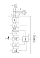
- the distributed power supply device 10 is interconnected to a commercial power system 13 via an output terminal 16. Further, the distributed power supply device 10 supplies AC power to the load device 12 via the output terminal 16. Note that AC power can be supplied to the load device 12 also from the commercial power system 13.
- the load device 12 is drawn for convenience as being connected to all of the U-phase power line, the O-phase power line, and the W-phase power line of the commercial system 13, it is connected to at least two power lines. Can be supplied.
- the solid lines connecting the functional blocks indicate the flow of power.
- broken lines connecting functional blocks indicate flows of control signals or information to be communicated. The communication indicated by the broken line may be wired communication or wireless communication.
- Distributed power supply device 10 includes a DC power supply unit 14, an orthogonal transformation unit 15, an output terminal 16, an earth leakage breaker 11, a DC relay 17, an interconnection relay 18, a ground fault sensor 19, a voltage sensor 20, and a control unit 21. .
- the DC power supply unit 14 is, for example, a solar cell, a fuel cell, or a secondary cell.
- the DC power supply unit 14 outputs DC power.
- the DC power supply unit 14 is a fuel cell. More specifically, in the present embodiment, the DC power supply unit 14 is a solid oxide fuel cell.
- the orthogonal transformation unit 15 includes, for example, a non-insulated inverter circuit, and converts direct current power output from the direct current power supply unit 14 into alternating current power.
- the orthogonal transformation unit 15 can convert AC power supplied from the commercial power system 13 into DC power when charging the secondary battery.
- the orthogonal transform unit 15 may adjust the DC power output from the DC power supply unit 14 by including a transformer circuit such as a non-insulated DC / DC converter.
- the output terminal 16 is a terminal connected to the commercial system 13.
- the AC power converted by the orthogonal transformation unit 15, that is, the power based on the DC power output from the DC power supply unit 14 is output from the distributed power supply device 10 to the commercial grid 13 via the output terminal 16.
- AC power supplied from the commercial power system 13 is supplied to the distributed power supply device 10 via the output terminal 16.
- the earth leakage breaker 11 is provided between the DC power supply unit 14 and the output terminal 16. More specifically, the leakage breaker 11 is provided between the orthogonal transformation unit 15 and the output terminal 16. The earth leakage breaker 11 shuts off the supply of AC power to the commercial power system 13 side in the case of detecting the leakage of the AC current, the case of detecting the overcurrent, and the like. In addition, the leakage breaker 11 can manually shut off the supply of AC power to the commercial power system 13 for an emergency and for maintenance.
- the earth leakage breaker 11 may cut off when the direct current flowing to the earth leakage breaker 11 exceeds the earth leakage current threshold.
- the leakage breaker 11 interrupts when the direct current exceeds the leakage current threshold and the leakage breaker breaking time has elapsed.
- the direct current relay 17 is, for example, an electromagnetic relay.
- the direct current relay 17 is provided between the direct current power supply unit 14 and the orthogonal transformation unit 15.
- the direct current relay 17 switches between conduction and interruption of direct current power between the direct current power supply unit 14 and the orthogonal transformation unit 15.
- the DC relay 17 switches between energization and interruption based on a control signal of the control unit 21.
- the interconnection relay 18 is, for example, an electromagnetic relay.
- the interconnection relay 18 is provided between the orthogonal transformation unit 15 and the leakage breaker 11.
- the interconnection relay 18 switches between energization and cutoff of AC power between the orthogonal transformation unit 15 and the earth leakage breaker 11.
- the interconnection relay 18 switches between energization and interruption based on a control signal of the control unit 21.
- the ground fault sensor 19 is, for example, a zero phase current transformer.
- the ground fault sensor 19 is provided between the interconnection relay 18 and the leakage breaker 11.
- the ground fault sensor 19 detects the zero-phase current component of the AC power output from the orthogonal transformation unit 15 as a DC ground fault current.
- the ground fault sensor 19 notifies the control unit 21 of the detected DC ground fault current.
- the voltage sensor 20 is provided, for example, between the interconnection relay 18 and the leakage breaker 11.
- the voltage sensor 20 detects, for example, the potential difference between the U phase and the O phase.
- the voltage sensor 20 notifies the control unit 21 of the detected potential difference.
- the voltage sensor 20 functions as a shutoff detection unit that detects shutoff of the electrical connection between the DC power supply unit 14 and the commercial system 13 together with the control unit 21.
- the control unit 21 includes, for example, one or more processors and a memory.
- the processor may include a general-purpose processor that loads a specific program to execute a specific function, and / or a dedicated processor specialized for a specific process.
- the dedicated processor may include an application specific integrated circuit (ASIC).
- the processor may include a programmable logic device (PLD).
- the PLD may include an FPGA (Field-Programmable Gate Array).
- the control unit 21 may include at least one of a System-on-a-Chip (SoC) in which one or more processors cooperate, and / or a System In a Package (SiP).
- SoC System-on-a-Chip
- SiP System In a Package
- the control unit 21 can receive power from any of the DC power supply unit 14 and the commercial power system 13.
- the control unit 21 receives power from the direct current power supply unit 14 via at least the direct current relay 17. Further, the control unit 21 receives power from the commercial power system 13 via at least the leakage breaker 11.
- the control unit 21 acquires a DC ground fault current and a potential difference from the ground fault sensor 19 and the voltage sensor 20, respectively. Further, the control unit 21 acquires various information from the DC power supply unit 14 and the orthogonal transformation unit 15. Furthermore, the control unit 21 may also communicate various information and control signals from the power management apparatus 22.
- the power management device 22 controls the power supply in the customer facility where the distributed power supply device 10 and the load device 12 are installed.
- the control unit 21 controls the DC power supply unit 14, the orthogonal transformation unit 15, the DC relay 17, and the interconnection relay 18 based on the acquired information and the control signal.
- control unit 21 detects the interruption of the electrical connection between DC power supply unit 14 and commercial system 13 including the interruption of earth leakage breaker 11 and the blackout of commercial system 13. Do.
- any conventionally known method may be used.
- blocking actually occurred to the moment of detecting is permitted.
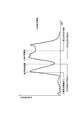
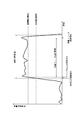
- the control unit 21 Based on the DC ground fault current acquired from the ground fault sensor 19, the control unit 21 recognizes the occurrence of the DC ground fault as a temporary temporary determination of the occurrence of the DC ground fault. As shown in FIG. 2, the control unit 21 recognizes that a direct current ground fault occurs when the time when the direct current ground fault current continuously exceeds the ground fault current threshold exceeds the ground fault time threshold.
- the ground fault current threshold is set to a value smaller than the leakage current threshold.
- the ground fault time threshold is set to a time shorter than the leak breaker breaking time.
- control unit 21 shuts off the interconnection relay 18 when recognizing the occurrence of the DC ground fault. Further, after the disconnection of the interconnection relay 18 based on the recognition of the occurrence of the DC ground fault, the control unit 21 does not determine the occurrence of the DC ground fault, which will be described later. After the lapse of time, the interconnection relay 18 is energized.
- the control unit 21 when detecting the disconnection of the electrical connection between the output terminal 16 and the commercial system 13, the control unit 21 causes a DC ground fault within a first determination time (first time) before the detection time of the disconnection. It is determined whether or not the occurrence of has been recognized. When the control unit 21 recognizes the occurrence of the DC ground fault within the first determination time, the control unit 21 determines the occurrence of the DC ground fault. The first determination time is determined to be short enough to determine that the earth leakage breaker 11 has tripped due to a DC ground fault.
- the earth leakage breaker 11 may cut off after the earth leakage breaker interruption time has elapsed since the DC ground fault current exceeded the earth leakage current threshold. Thereafter, the control unit 21 detects the interruption of the leak breaker 11 and determines the occurrence of the DC ground fault since the occurrence of the DC ground fault is recognized at the first time before the detection time.
- control unit 21 When the control unit 21 recognizes the occurrence of the DC ground fault a predetermined number of times within the second determination time from the recognition of the occurrence of the DC ground fault, the control unit 21 determines the occurrence of the DC ground fault.
- control unit 21 shuts off the interconnection relay 18 when determining the occurrence of the DC ground fault. Furthermore, the control unit 21 stops the orthogonal transformation unit 15 when determining the occurrence of the DC ground fault. The control unit 21 stops the DC power supply unit 14 and shuts off the DC relay 17 after the power securing time (second time) has elapsed from the determination time of the occurrence of the DC ground fault.
- the power securing time is set to a time longer than the time required for generation and transmission of a notification signal described later.
- control unit 21 generates a notification signal indicating that the direct current ground fault is occurring in the direct current power supply unit 14 during the time when the power securing time elapses from the determination time of the occurrence of the direct current ground fault. Furthermore, the control unit 21 transmits the generated notification signal to, for example, the power management apparatus 22, a server that manages the distributed power supply apparatus 10, and the distributed power supply apparatus 10 or a remote controller of the power management apparatus 22.
- the power management apparatus 22 that has acquired the notification signal, the server, the remote controller, and the like notify the user of the occurrence of the DC ground fault by displaying a warning image and generating a warning voice.
- control unit 21 determines the occurrence of the DC ground fault
- the control unit 21 continues the driving of the DC power supply unit 14 even if the disconnection of the electrical connection between the output terminal 16 and the commercial system 13 is detected.
- the control part 21 transfers to a stand-alone output possible state, when the said interruption
- the control unit 21 directly supplies AC power to a specific load device without passing through the leakage breaker 11, the DC power supply unit 14, the orthogonal transformation unit 15, and The DC relay 17 is controlled.
- the control unit 21 detects the disconnection of the electrical connection, and since the occurrence of the DC ground fault is not recognized at the first time before the detection time, the occurrence of the DC ground fault is determined. It will shift to the stand-alone output possible state without doing.
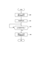
- ground fault recognition processing executed by the control unit 21 in the present embodiment will be described using the flowchart of FIG. 5.
- the ground fault recognition process is started each time the control unit 21 acquires a DC ground fault current from the ground fault sensor 19.
- control unit 21 determines whether or not the DC ground current exceeds the ground current threshold. If the ground fault current threshold is not exceeded, the process proceeds to step S101. If the ground fault current threshold is exceeded, the process proceeds to step S102.
- step S101 the control unit 21 stops clocking for ground fault recognition and resets it to zero. After stopping the clocking, the ground fault recognition process ends.
- step S102 the control unit 21 determines whether or not clocking for ground fault recognition is in progress. If not, the process proceeds to step S103. If it is running, the process proceeds to step S104.
- step S103 the control unit 21 starts clocking for ground fault recognition. After starting, the process proceeds to step S104.
- step S104 the control unit 21 determines whether the timed time for ground fault recognition exceeds the ground fault time threshold. If the ground fault time threshold is not exceeded, the ground fault recognition process ends. If the ground fault time threshold is exceeded, the process proceeds to step S105.
- step S105 the control unit 21 recognizes the occurrence of the ground fault current. After the occurrence of the ground fault current is recognized, the ground fault recognition process ends.
- the first determination process starts when the disconnection detection unit detects disconnection of the electrical connection between the output terminal 16 and the commercial system 13.
- step S200 the control unit 21 determines whether or not the occurrence of the ground fault current is determined by a second determination determination process described later. If determined, the first determination processing ends. If not determined, the process proceeds to step S201.
- step S201 the control unit 21 determines whether or not the occurrence of the ground fault current has been recognized within a first determination time before the detection of the shutoff. If it is recognized, the process proceeds to step S202. If not, the process proceeds to step S203.
- control unit 21 determines the occurrence of the ground fault current. After the occurrence of the ground fault current is determined, the first determination process ends.
- step S203 the control unit 21 shifts to the independent output possible state. After transition, the first determination process ends.
- the second determination process is started each time the control unit 21 recognizes the occurrence of the ground fault current.
- step S300 the control unit 21 determines whether or not counting for determining the determination is in progress. If not, the process proceeds to step S301. If it is running, the process proceeds to step S302.
- step S301 the control unit 21 starts counting time for determining determination. After starting, the process proceeds to step S302.
- step S302 the control unit 21 determines whether a second determination time has elapsed since the start of counting for determining the determination in step S301. If the second determination time has not elapsed, the process proceeds to step S303. If the second determination time has elapsed, the process proceeds to step S306.
- step S303 the control unit 21 increments the number of times of ground fault recognition by +1. After incrementing, the process proceeds to step S304.
- step S304 the control unit 21 determines whether the number of times of ground fault recognition has reached a predetermined number. If it has, the process proceeds to step S305. If not, the process proceeds to step S307.
- step S305 the control unit 21 determines the occurrence of the ground fault current. After the determination, the second determination process ends.
- step S306 the control unit 21 resets the number of times of ground fault recognition to zero. After reset, the process proceeds to step S307.
- step S307 the control unit 21 shuts off the interconnection relay 18. After blocking, the process proceeds to step S308.
- step S308 the control unit 21 determines whether or not the temporary disconnection time has elapsed from the time of disconnection of the interconnection relay 18 in step S307. If the temporary shutoff time has not elapsed, the process returns to step S308. If the temporary cutoff time has elapsed, the process proceeds to step S309.
- step S309 the control unit 21 energizes the interconnection relay 18. After energization of the interconnection relay 18, the second determination process ends.
- the determination process starts when the control unit 21 determines the occurrence of the ground fault current.
- step S400 the control unit 21 shuts off the interconnection relay 18. Further, the control unit 21 stops the orthogonal transformation unit 15. After instructing the disconnection of the interconnection relay 18 and the stop of the orthogonal transformation unit 15, the process proceeds to step S401.
- step S401 the control unit 21 generates a notification signal. Furthermore, the control unit 21 outputs the generated notification signal. After outputting the notification signal, the process proceeds to step S402.
- step S402 the control unit 21 determines whether or not the power securing time has elapsed since the determination of the occurrence of the ground fault current. If the power reservation time has not elapsed, the process returns to step S402. If the power securing time has elapsed, the process proceeds to step S403.
- step S403 the control unit 21 shuts off the DC relay 17. Further, the control unit 21 stops the DC power supply unit 14. After the shutoff of the DC relay 17 and the command to stop the DC power supply unit 14, the determination process ends.
- the distributed power supply device 10 configured as described above generates the DC ground fault if the DC ground fault is tentatively determined within a first time before the detection of the shutoff by the shutoff detection unit. Determine.
- the distributed power supply device 10 causes the DC ground fault even when the electrical connection between the output terminal 16 and the commercial system 13 is interrupted, such as the interruption of the earth leakage breaker 11 or the like. It can be determined whether or not it is based on Therefore, distributed power supply device 10 can determine the occurrence of a DC ground fault even in the configuration where earth leakage breaker 11 is connected.
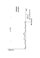
- the distributed power supply device 10 when the time when the DC ground fault current exceeds the ground fault current threshold smaller than the ground fault current threshold exceeds the ground fault time threshold shorter than the leak breaker breaker time, Temporarily determine the occurrence. As shown in FIG. 9, in the configuration in which the leakage current threshold is smaller than the ground fault current threshold, it may occur that the DC ground fault current does not exceed the ground fault current threshold while the DC ground fault occurs. When such an event occurs, the earth leakage breaker 11 may shut off prior to the tentative determination of the DC ground fault. Further, as shown in FIG.
- the leakage breaker interruption time before the time when the ground fault time threshold is exceeded when the DC ground fault current rises rapidly. Exceeding can occur. When such an event occurs, the earth leakage breaker 11 may shut off prior to the tentative determination of the DC ground fault.
- ground fault current threshold is smaller than leakage current threshold and ground fault time threshold is shorter than earth leakage breaker interruption time, occurrence of DC earth fault is detected when earth leakage breaker 11 is interrupted. The possibilities can be improved.
- the distributed power supply device 10 which concerns on this embodiment shuts off the direct current relay 17 after progress of 2nd time from the time of determination of generation
- the distributed power supply device 10 generates a notification signal until the second time elapses. Therefore, when the distributed power supply 10 stops, the distributed power supply 10 can notify the user of the reason for the stop.
- the distributed power supply device 10 maintains the output of the DC power from the DC power supply unit 14 until the occurrence of the DC ground fault is determined. Therefore, distributed power supply device 10 transitions to a stand-alone output enabled state in which power is supplied to a specific load device when a DC ground fault does not occur and shutoff by the shutoff detection unit is detected due to a simple power failure or the like. obtain.
- the distributed power supply device 10 is configured to have a single control unit 21, but is not limited to such a configuration.
- the control unit 21 controls the overall operation of the distributed power supply apparatus 10, and at least one of a power control unit that controls only the drive of the DC power supply unit 14 and a conversion control unit that controls only the drive of the orthogonal transformation unit 15. And a controller.
- at least one of the power control unit and the conversion control unit may execute part of the processing and control performed by the control unit 21 in the present embodiment.
- the distributed power supply device 10 stops the DC power supply unit 14 and cuts off the DC relay 17 after the power securing time has elapsed after the determination of the occurrence of the ground fault current, but the power securing time has elapsed. For example, after determination of the occurrence of the ground fault current, stop and shut off may be performed immediately.
- the distributed power supply device 10 includes the earth leakage breaker 11.
- the earth leakage breaker 11 has a layout capable of operating equivalent to the operation characteristics of the present disclosure, It may be provided outside.
- the system is disclosed as having various modules and / or units for performing specific functions, and these modules and units are schematically shown to briefly describe their functionality. It should be noted that what is shown is not necessarily indicative of a specific hardware and / or software. In that sense, these modules, units, and other components may be hardware and / or software implemented to perform substantially the particular functions described herein. The various functions of different components may be any combination or separation of hardware and / or software, and may be used separately or in any combination. Also, connect input / output or I / O devices or user interfaces, including but not limited to keyboards, displays, touch screens, pointing devices, etc., directly to the system or through intervening I / O controllers Can. As such, various aspects of the disclosure may be embodied in many different aspects, all of which are within the scope of the disclosure.
Landscapes
- Engineering & Computer Science (AREA)
- Power Engineering (AREA)
- Emergency Protection Circuit Devices (AREA)
- Protection Of Static Devices (AREA)
- Inverter Devices (AREA)
Abstract
分散電源装置10は直流電源部14と地絡センサ19と漏電ブレーカ11と遮断検出部と制御部21とを有する。直流電源部14は直流電力を出力する。地絡センサ19は直流電源部における直流地絡電流を検出する。漏電ブレーカ11は出力端子と直流電源部との間に設けられている。遮断検出部は直流電源部14と商用系統13との電気的接続の遮断を検出する。制御部21は遮断検出部が遮断を検出する時以前の第1の時間内に直流地絡の発生を認識する場合直流地絡の発生を確定する。制御部21は地絡センサ19から取得する直流地絡電流に基づいて直流地絡の発生を認識する。
Description
本出願は、2017年8月30日に日本国に特許出願された特願2017-165231の優先権を主張するものであり、この先の出願の開示全体をここに参照のために取り込む。
本開示は、分散電源装置、および分散電源装置の制御方法に関するものである。
直流電源部から出力される直流電力を直交変換して出力する分散電源装置が、需要家施設において用いられている。安全性の確保および緊急停止のために、分散電源装置における系統入出力端子に漏電ブレーカが設けられることがある。一般的な漏電ブレーカは交流電流の漏電により遮断する。分散電源装置は、漏電ブレーカが遮断する場合、停電が発生したと判断し、特定の負荷機器に自立出力により電力を供給するように制御されることがある。
分散電源装置の直流電源部において、直流地絡が発生するおそれがある。そこで、直流電源部における地絡電流を検出し、当該地絡電流に基づいて直流地絡の発生を確定して、分散電源装置からの交流電力の出力を停止させることが提案されている(特許文献1参照)。
上述した諸課題を解決すべく、第1の観点による分散電源装置は、
直流電力を出力する直流電源部と、
前記直流電源部における直流地絡電流を検出する地絡センサと、
前記直流電源部から出力される直流電力に基づく電力を外部に出力するための出力端子と、前記直流電源部との間に設けられている漏電ブレーカと、
前記直流電源部と前記出力端子に接続される系統電力と商用系統との電気的接続の遮断を検出する遮断検出部と、
前記遮断検出部が前記遮断を検出する時以前の第1の時間内に、前記地絡センサから取得する前記直流地絡電流に基づいて直流地絡の発生を認識する場合、直流地絡の発生を確定する制御部と、を備える。
直流電力を出力する直流電源部と、
前記直流電源部における直流地絡電流を検出する地絡センサと、
前記直流電源部から出力される直流電力に基づく電力を外部に出力するための出力端子と、前記直流電源部との間に設けられている漏電ブレーカと、
前記直流電源部と前記出力端子に接続される系統電力と商用系統との電気的接続の遮断を検出する遮断検出部と、
前記遮断検出部が前記遮断を検出する時以前の第1の時間内に、前記地絡センサから取得する前記直流地絡電流に基づいて直流地絡の発生を認識する場合、直流地絡の発生を確定する制御部と、を備える。
上述したように本開示の解決手段を装置、及びシステムとして説明してきたが、本開示は、これらを含む態様としても実現し得るものであり、また、これらに実質的に相当する方法、プログラム、プログラムを記録した記憶媒体としても実現し得るものであり、本開示の範囲にはこれらも包含されるものと理解されたい。
例えば方法として具現化した、第2の観点による分散電源装置の制御方法は、
直流電力を出力する直流電源部と、前記直流電源部における直流地絡電流を検出する地絡センサと、前記直流電源部から出力される直流電力に基づく電力を外部に出力するための出力端子と、前記直流電源部との間に設けられている漏電ブレーカと、前記直流電源部と前記出力端子に接続される系統電源との電気的接続の遮断を検出する遮断検出部とを有する分散電源装置の制御方法であって、
前記遮断検出部による前記遮断の検出時に該検出時以前の第1の時間内に、前記地絡センサから取得する前記直流地絡電流に基づいて直流地絡の発生を認識しているか否かを判別するステップと、
前記第1の時間内に前記直流地絡の発生を認識している場合、直流地絡の発生を確定するステップと、を備える。
直流電力を出力する直流電源部と、前記直流電源部における直流地絡電流を検出する地絡センサと、前記直流電源部から出力される直流電力に基づく電力を外部に出力するための出力端子と、前記直流電源部との間に設けられている漏電ブレーカと、前記直流電源部と前記出力端子に接続される系統電源との電気的接続の遮断を検出する遮断検出部とを有する分散電源装置の制御方法であって、
前記遮断検出部による前記遮断の検出時に該検出時以前の第1の時間内に、前記地絡センサから取得する前記直流地絡電流に基づいて直流地絡の発生を認識しているか否かを判別するステップと、
前記第1の時間内に前記直流地絡の発生を認識している場合、直流地絡の発生を確定するステップと、を備える。
以下、本開示を適用した分散電源装置の実施形態について、図面を参照して説明する。
図1に示すように、本開示の一実施形態に係る分散電源装置10は、出力端子16を介して、商用系統13に連系されている。また、分散電源装置10は、出力端子16を介して、負荷機器12に交流電力を供給する。なお、負荷機器12には、商用系統13からも交流電力が供給され得る。図1において、負荷機器12は、商用系統13のU相電力線、O相電力線、およびW相電力線のすべてに接続されるように便宜上描かれているが、少なくとも2つの電力線に接続され、交流電力が供給され得る。以後の図において、各機能ブロックを結ぶ実線は、電力の流れを示す。また、図1において、各機能ブロックを結ぶ破線は、制御信号または通信される情報の流れを示す。破線が示す通信は有線通信であってもよいし、無線通信であってもよい。
分散電源装置10は、直流電源部14、直交変換部15、出力端子16、漏電ブレーカ11、直流リレー17、連系リレー18、地絡センサ19、電圧センサ20、および制御部21を含んでいる。
直流電源部14は、例えば、太陽電池、燃料電池、二次電池である。直流電源部14は、直流電力を出力する。本実施形態においては、直流電源部14は、燃料電池である。さらに具体的には、本実施形態において、直流電源部14は、固体酸化物形燃料電池である。
直交変換部15は、例えば、非絶縁型のインバータ回路を含み、直流電源部14が出力する直流電力を交流電力に変換する。なお、直流電源部14が二次電池である構成においては、直交変換部15は、二次電池への充電時に、商用系統13から供給される交流電力を直流電力に変換可能である。なお、直交変換部15は、非絶縁型のDC/DCコンバータなどの変圧回路を含んで、直流電源部14が出力する直流電力を調圧してよい。
出力端子16は、商用系統13と接続する端子である。直交変換部15により変換された交流電力、すなわち、直流電源部14が出力する直流電力に基づく電力が、分散電源装置10から出力端子16を介して、商用系統13側に出力される。なお、直流電源部14が二次電池である構成においては、商用系統13から供給される交流電力が、出力端子16を介して、分散電源装置10に給電される。
漏電ブレーカ11は、直流電源部14および出力端子16の間に設けられている。漏電ブレーカ11は、さらに具体的には、直交変換部15および出力端子16の間に設けられている。漏電ブレーカ11は、交流電流の漏電を検出する場合および過電流を検出する場合などにおいて、商用系統13側への交流電力の供給を遮断する。また、漏電ブレーカ11は、緊急時およびメンテナンスのために手動で、商用系統13側への交流電力の供給を遮断可能である。
さらに、漏電ブレーカ11は、漏電ブレーカ11に流れる直流電流が漏電電流閾値を超える場合、遮断することがある。直流電流に基づいて遮断する場合、漏電ブレーカ11は、直流電流が漏電電流閾値を超えた時から漏電ブレーカ遮断時間の経過時に遮断する。
直流リレー17は、例えば、電磁リレーである。直流リレー17は、直流電源部14および直交変換部15の間に設けられている。直流リレー17は、直流電源部14および直交変換部15の間における直流電力の通電および遮断を切替える。直流リレー17は、制御部21の制御信号に基づいて、通電および遮断を切替える。
連系リレー18は、例えば、電磁リレーである。連系リレー18は、直交変換部15および漏電ブレーカ11の間に設けられている。連系リレー18は、直交変換部15および漏電ブレーカ11の間における交流電力の通電および遮断を切替える。連系リレー18は、制御部21の制御信号に基づいて、通電および遮断を切替える。
地絡センサ19は、例えば零相変流器である。地絡センサ19は、連系リレー18および漏電ブレーカ11の間に設けられている。地絡センサ19は、直交変換部15から出力される交流電力の零相電流成分を、直流地絡電流として検出する。地絡センサ19は、検出した直流地絡電流を制御部21に通知する。
電圧センサ20は、例えば、連系リレー18および漏電ブレーカ11の間に設けられている。電圧センサ20は、例えば、U相およびO相の電位差を検出する。電圧センサ20は、検出した電位差を制御部21に通知する。なお、後述するように、電圧センサ20は、制御部21とともに直流電源部14および商用系統13の間の電気的接続の遮断を検出する遮断検出部として機能する。
制御部21は、例えば、1以上のプロセッサおよびメモリを含む。プロセッサは、特定のプログラムを読み込ませて特定の機能を実行する汎用のプロセッサ、および特定の処理に特化した専用のプロセッサの少なくともいずれかを含んでよい。専用のプロセッサは、特定用途向けIC(ASIC;Application Specific Integrated Circuit)を含んでよい。プロセッサは、プログラマブルロジックデバイス(PLD;Programmable Logic Device)を含んでよい。PLDは、FPGA(Field-Programmable Gate Array)を含んでよい。制御部21は、1つまたは複数のプロセッサが協働するSoC(System-on-a-Chip)、およびSiP(System In a Package)の少なくともいずれかを含んでもよい。
制御部21は、直流電源部14および商用系統13のいずれからも受電可能である。制御部21は、直流電源部14からは、少なくとも直流リレー17を介して電力を受電する。また、制御部21は、商用系統13からは、少なくとも漏電ブレーカ11を介して電力を受電する。
制御部21は、地絡センサ19および電圧センサ20から、それぞれ直流地絡電流および電位差を取得する。また、制御部21は、直流電源部14および直交変換部15から、多様な情報を取得する。さらに、制御部21は、電力管理装置22からも多様な情報および制御信号を通信してよい。なお、電力管理装置22は、分散電源装置10および負荷機器12が設置される需要家施設内の電力供給を制御する。制御部21は、取得した情報および制御信号に基づいて、直流電源部14、直交変換部15、直流リレー17、および連系リレー18を制御する。
例えば、制御部21は、電圧センサ20から取得する電位差に基づいて、漏電ブレーカ11の遮断および商用系統13の停電を含む、直流電源部14および商用系統13の間の電気的接続の遮断を検出する。電位差に基づく当該電気的接続の遮断の検出には、従来公知のいかなる方法を用いてよい。なお、当該電気的接続の遮断の検出には、実際に遮断が起きた瞬間から検出する瞬間までの間のタイムラグが許容されている。
また、制御部21は、地絡センサ19から取得する直流地絡電流に基づいて、直流地絡の発生の一次的な仮確定として、直流地絡の発生を認識する。図2に示すように、制御部21は、直流地絡電流が地絡電流閾値を連続して超える時間が、地絡時間閾値を超える場合、直流地絡が発生していると認識する。なお、地絡電流閾値は、漏電電流閾値より小さな値に定められている。また、地絡時間閾値は、漏電ブレーカ遮断時間より短い時間に定められている。
また、制御部21は、直流地絡の発生を認識する場合、連系リレー18を遮断させる。また、制御部21は、直流地絡の発生の認識に基づき連系リレー18の遮断後、後述する直流地絡の発生の確定を行わない場合、連系リレー18の遮断時から仮遮断時間の経過後に、連系リレー18を通電させる。
また、制御部21は、出力端子16および商用系統13の間の電気的接続の遮断を検出する場合、当該遮断の検出時期以前の第1の判別時間(第1の時間)内に直流地絡の発生を認識していたか否かを判別する。制御部21は、当該第1の判別時間内に直流地絡の発生を認識していた場合、直流地絡の発生を確定する。なお、第1の判別時間は、直流地絡に起因して漏電ブレーカ11が遮断したと判別させ得る短さに定められている。
例えば、図3に示すように、直流地絡電流が地絡時間閾値以上の間、地絡電流閾値を超えながら、直流地絡電流が漏電電流閾値を超えることが生じ得る。このような場合に、漏電ブレーカ11は直流地絡電流が漏電電流閾値を超えてから漏電ブレーカ遮断時間の経過後に遮断する場合がある。この後、制御部21は、漏電ブレーカ11の遮断を検出し、検出時期以前の第1の時間に、直流地絡の発生が認識されているので、直流地絡の発生を確定する。
また、制御部21は、直流地絡の発生の認識から第2の判別時間以内に、直流地絡の発生を所定回数だけ認識した場合、直流地絡の発生を確定する。
また、制御部21は、直流地絡の発生を確定する場合、連系リレー18を遮断させる。さらに、制御部21は、直流地絡の発生を確定する場合、直交変換部15を停止させる。制御部21は、直流地絡の発生の確定時から電力確保時間(第2の時間)が経過した後、直流電源部14を停止させ、かつ直流リレー17を遮断させる。なお、電力確保時間は、後述する報知信号の生成および送信にかかる時間より長い時間に定められている。
また、制御部21は、直流地絡の発生の確定時から電力確保時間が経過するまでの間に、直流電源部14に直流地絡が発生していることを示す報知信号を生成する。さらに、制御部21は、生成した報知信号を、例えば、電力管理装置22、分散電源装置10を管理するサーバ、および分散電源装置10または電力管理装置22のリモートコントローラなどに送信する。なお、報知信号を取得した電力管理装置22、サーバ、およびリモートコントローラなどは、警告画像の表示および警告音声の発生などにより、直流地絡の発生をユーザに報知する。
また、制御部21は、直流地絡の発生を確定する前には、出力端子16および商用系統13の間の電気的接続の遮断を検出したとしても、直流電源部14の駆動を続けさせることにより、直流電力の出力を維持させる。また、制御部21は、当該遮断を検出し、かつ直流地絡の発生を確定しない場合、自立出力可能状態に移行する。なお、自立出力可能状態において、制御部21は、特定の負荷機器に対して、漏電ブレーカ11を介さずに、直接、交流電力を供給するように、直流電源部14、直交変換部15、および直流リレー17を制御する。
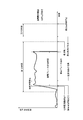
例えば、図4に示すように、交流電流の漏電および過電流などに基づく漏電ブレーカ11の自動遮断、ユーザによる漏電ブレーカ11の手動遮断、ならびに停電などの、直流電源部14および商用系統13の間の電気的接続の遮断が生じ得る。このような場合に、制御部21は、当該電気的接続の遮断を検出し、検出時期以前の第1の時間に、直流地絡の発生が認識されていないので、直流地絡の発生を確定せず、自立出力可能状態に移行する。
次に、本実施形態において制御部21が実行する、地絡認識処理について、図5のフローチャートを用いて説明する。地絡認識処理は、制御部21が地絡センサ19から直流地絡電流を取得する毎に開始する。
ステップS100において、制御部21は、直流地絡電流が地絡電流閾値を超えるか否かを判別する。地絡電流閾値を超えない場合、プロセスはステップS101に進む。地絡電流閾値を超える場合、プロセスはステップS102に進む。
ステップS101では、制御部21は、地絡認識のための計時を停止し、ゼロにリセットする。計時の停止後、地絡認識処理は終了する。
ステップS102では、制御部21は、地絡認識のための計時の実行中であるか否かを判別する。実行していない場合、プロセスはステップS103に進む。実行中である場合、プロセスはステップS104に進む。
ステップS103では、制御部21は、地絡認識のための計時を開始する。開始後、プロセスはステップS104に進む。
ステップS104では、制御部21は、地絡認識のための計時時間が地絡時間閾値を越えているか否かを判別する。地絡時間閾値を超えていない場合、地絡認識処理は終了する。地絡時間閾値を超えている場合、プロセスはステップS105に進む。
ステップS105では、制御部21は、地絡電流の発生を認識する。地絡電流の発生の認識後、地絡認識処理は終了する。
次に、本実施形態において制御部21が実行する、第1の確定判別処理について、図6のフローチャートを用いて説明する。第1の確定判別処理は、遮断検出部が出力端子16および商用系統13の間の電気的接続の遮断を検出する時に開始する。
ステップS200において、制御部21は、後述する第2の確定判別処理により、地絡電流の発生を確定しているか否かを判別する。確定している場合、第1の確定判別処理は終了する。確定していない場合、プロセスはステップS201に進む。
ステップS201では、制御部21は、遮断の検出時以前の第1の判別時間内に、地絡電流の発生の認識をしていたか否かを判別する。認識していた場合、プロセスはステップS202に進む。認識していなかった場合、プロセスはステップS203に進む。
ステップS202では、制御部21は、地絡電流の発生を確定する。地絡電流の発生の確定後、第1の確定判別処理は終了する。
ステップS203では、制御部21は、自立出力可能状態に移行する。移行後、第1の確定判別処理は終了する。
次に、本実施形態において制御部21が実行する、第2の確定判別処理について、図7のフローチャートを用いて説明する。第2の確定判別処理は、制御部21が地絡電流の発生を認識する毎に開始する。
ステップS300において、制御部21は、確定の判別のための計時の実行中であるか否かを判別する。実行していない場合、プロセスはステップS301に進む。実行中である場合、プロセスはステップS302に進む。
ステップS301では、制御部21は、確定の判別のための計時を開始する。開始後、プロセスはステップS302に進む。
ステップS302では、制御部21は、ステップS301における確定の判別のための計時の開始後から第2の判別時間が経過しているか否かを判別する。第2の判別時間が経過していない場合、プロセスはステップS303に進む。第2の判別時間が経過している場合、プロセスはステップS306に進む。
ステップS303では、制御部21は、地絡認識の回数に+1をインクリメントする。インクリメント後、プロセスはステップS304に進む。
ステップS304では、制御部21は、地絡認識の回数が所定回数に達しているか否かを判別する。達している場合、プロセスはステップS305に進む。達していない場合、プロセスはステップS307に進む。
ステップS305では、制御部21は、地絡電流の発生を確定する。確定後、第2の確定判別処理は終了する。
ステップS306では、制御部21は、地絡認識の回数をゼロにリセットする。リセット後、プロセスはステップS307に進む。
ステップS307では、制御部21は、連系リレー18を遮断させる。遮断後、プロセスはステップS308に進む。
ステップS308では、制御部21は、ステップS307において連系リレー18を遮断時から仮遮断時間が経過しているか否かを判別する。仮遮断時間を経過していない場合、プロセスはステップS308に戻る。仮遮断時間を経過している場合、プロセスはステップS309に進む。
ステップS309では、制御部21は、連系リレー18を通電させる。連系リレー18の通電後、第2の確定判別処理は終了する。
次に、本実施形態において制御部21が実行する、確定処理について、図8のフローチャートを用いて説明する。確定処理は、制御部21が地絡電流の発生を確定する時に開始する。
ステップS400において、制御部21は、連系リレー18を遮断させる。また、制御部21は、直交変換部15を停止させる。連系リレー18の遮断および直交変換部15の停止の指令後、プロセスはステップS401に進む。
ステップS401では、制御部21は、報知信号を生成する。さらに、制御部21は、生成した報知信号を出力する。報知信号の出力後、プロセスはステップS402に進む。
ステップS402では、制御部21は、地絡電流の発生の確定時から電力確保時間が経過したか否かを判別する。電力確保時間が経過していない場合、プロセスはステップS402に戻る。電力確保時間が経過している場合、プロセスはステップS403に進む。
ステップS403では、制御部21は、直流リレー17を遮断させる。また、制御部21は、直流電源部14を停止させる。直流リレー17の遮断および直流電源部14の停止の指令後、確定処理は終了する。
以上のような構成の本実施形態の分散電源装置10は、遮断検出部による遮断の検出時以前の第1の時間内に、直流地絡の発生を仮確定する場合、直流地絡の発生を確定する。このような構成により、分散電源装置10は、漏電ブレーカ11の遮断などのように、出力端子16および商用系統13との間の電気的接続の遮断時であっても、当該遮断が直流地絡に基づくか否かを判別し得る。したがって、分散電源装置10は、漏電ブレーカ11が接続される構成においても、直流地絡の発生を確定し得る。
また、本実施形態に係る分散電源装置10は、直流地絡電流が漏電電流閾値より小さな地絡電流閾値を超える時間が、漏電ブレーカ遮断時間より短い地絡時間閾値を超える場合、直流地絡の発生を仮確定する。図9に示すように、漏電電流閾値が地絡電流閾値より小さい構成においては、直流地絡が発生しながらも直流地絡電流が地絡電流閾値を超えないこと生じ得る。そのような事象が生じる場合、直流地絡の仮確定の前に漏電ブレーカ11が遮断し得る。また、図10に示すように、漏電ブレーカ遮断時間が地絡電流閾値より短い構成においては、直流地絡電流が急上昇する場合に地絡時間閾値を超える時間が経過する前に漏電ブレーカ遮断時間を超えることが生じ得る。そのような事象が生じる場合、直流地絡の仮確定の前に漏電ブレーカ11が遮断し得る。上述の構成の分散電源装置10では、地絡電流閾値が漏電電流閾値より小さく且つ地絡時間閾値が漏電ブレーカ遮断時間より短いので、漏電ブレーカ11が遮断する場合、直流地絡の発生を検知する可能性を向上し得る。
また、本実施形態に係る分散電源装置10は、直流地絡の発生の確定時から第2の時間の経過後に直流リレー17を遮断させる。したがって、分散電源装置10は、直流地絡の発生後の分散電源装置10の駆動を停止する際に、報知信号の生成などの望ましい処理を実行するために制御部21が用いる電力を確保させ得る。
また、本実施形態に係る分散電源装置10は、第2の時間が経過するまでの間に報知信号を生成する。したがって、分散電源装置10は、分散電源装置10が停止する際に、停止の理由をユーザに報知し得る。
また、本実施形態に係る分散電源装置10は、直流地絡の発生を確定するまで、直流電源部14からの直流電力の出力を維持する。したがって、分散電源装置10は、直流地絡が発生せずに、単なる停電などで遮断検出部による遮断が検出された場合、特定の負荷機器に対して電力を供給する自立出力可能状態に移行し得る。
本開示を諸図面や実施例に基づき説明してきたが、当業者であれば本開示に基づき種々の変形や修正を行うことが容易であることに注意されたい。従って、これらの変形や修正は本開示の範囲に含まれることに留意されたい。
例えば、本実施形態において、分散電源装置10は、単一の制御部21を有する構成であるが、このような構成に限定されない。例えば、制御部21は、直流電源部14の駆動のみを制御する電源制御部および直交変換部15の駆動のみを制御する変換制御部の少なくともいずれかと、分散電源装置10の全体の制御を行なう全体制御部とを含んでいてよい。当該構成においては、本実施形態において制御部21が行っている処理および制御の一部を、電源制御部および変換制御部の少なくともいずれかが実行してよい。
また、本実施形態において、分散電源装置10は、地絡電流発生の確定後、電力確保時間が経過した後に直流電源部14の停止および直流リレー17を遮断するが、電力確保時間が経過すること無く、例えば地絡電流発生の確定後、即座に停止および遮断を行ってよい。
また、本実施形態において、分散電源装置10は漏電ブレーカ11を含むが、例えば、漏電ブレーカ11は、本開示の動作特性と同等の動作をするようなレイアウトが可能であれば、分散電源装置の外部に設けられてよい。
なお、ここでは、特定の機能を実行する種々のモジュール及び/またはユニットを有するものとしてのシステムを開示しており、これらのモジュール及びユニットは、その機能性を簡略に説明するために模式的に示されたものであって、必ずしも、特定のハードウェア及び/またはソフトウェアを示すものではないことに留意されたい。その意味において、これらのモジュール、ユニット、その他の構成要素は、ここで説明された特定の機能を実質的に実行するように実装されたハードウェア及び/またはソフトウェアであればよい。異なる構成要素の種々の機能は、ハードウェア及び/もしくはソフトウェアのいかなる組合せまたは分離したものであってもよく、それぞれ別々に、またはいずれかの組合せにより用いることができる。また、キーボード、ディスプレイ、タッチスクリーン、ポインティングデバイス等を含むがこれらに限られない入力/出力もしくはI/Oデバイスまたはユーザインターフェースは、システムに直接にまたは介在するI/Oコントローラを介して接続することができる。このように、本開示内容の種々の側面は、多くの異なる態様で実施することができ、それらの態様はすべて本開示内容の範囲に含まれる。
10 分散電源装置
11 漏電ブレーカ
12 負荷機器
13 商用系統
14 直流電源部
15 直交変換部
16 出力端子
17 直流リレー
18 連系リレー
19 地絡センサ
20 電圧センサ
21 制御部
22 電力管理装置
11 漏電ブレーカ
12 負荷機器
13 商用系統
14 直流電源部
15 直交変換部
16 出力端子
17 直流リレー
18 連系リレー
19 地絡センサ
20 電圧センサ
21 制御部
22 電力管理装置
Claims (12)
- 直流電力を出力する直流電源部と、
前記直流電源部における直流地絡電流を検出する地絡センサと、
前記直流電源部から出力される直流電力に基づく電力を外部に出力するための出力端子と前記直流電源部との間に設けられている漏電ブレーカと、
前記直流電源部と前記出力端子に接続される商用系統との間の電気的接続の遮断を検出する遮断検出部と、
前記遮断検出部が前記遮断を検出する時以前の第1の時間内に、前記地絡センサから取得する前記直流地絡電流に基づいて直流地絡の発生を認識する場合、直流地絡の発生を確定する制御部と、を備える
分散電源装置。 - 請求項1に記載の分散電源装置において、
前記漏電ブレーカは、該漏電ブレーカに流れる直流電流が漏電電流閾値を超えた後、漏電ブレーカ遮断時間の経過時に遮断し、
前記制御部は、前記地絡センサに検出される前記直流地絡電流が前記漏電電流閾値より小さな地絡電流閾値を超える時間が、前記漏電ブレーカ遮断時間より短い地絡時間閾値を超える場合、直流地絡の発生を認識する
分散電源装置。 - 請求項1または2に記載の分散電源装置において、
前記直流電源部が出力する直流電力を交流電力に変換する直交変換部と、
前記直流電源部および前記直交変換部の間に設けられる直流リレーと、をさらに備え、
前記制御部は、前記直流リレーを介して、前記直流電源部から電力を取得し、
前記制御部は、直流地絡の発生の確定時から第2の時間の経過後に前記直流リレーを遮断させる
分散電源装置。 - 請求項1から3のいずれか1項に記載の分散電源装置において、
前記制御部は、直流地絡の発生を確定した後から前記第2の時間が経過するまでの間に、直流地絡の発生を示す報知信号を出力する
分散電源装置。 - 請求項1から4のいずれか1項に記載の分散電源装置において、
前記制御部は、直流地絡の発生を確定するまで、前記直流電源部からの前記直流電力の出力を維持する
分散電源装置。 - 請求項1から5のいずれか1項に記載の分散電源装置において、
前記制御部は、前記第1の時間内に、前記直流地絡の発生を認識しない場合、自立出力可能状態に移行する
分散電源装置。 - 直流電力を出力する直流電源部と、前記直流電源部における直流地絡電流を検出する地絡センサと、前記直流電源部から出力される直流電力に基づく電力を外部に出力するための出力端子と、前記直流電源部との間に設けられている漏電ブレーカと、前記直流電源部と前記出力端子に接続される系統電源との電気的接続の遮断を検出する遮断検出部とを有する分散電源装置の制御方法であって、
前記遮断検出部による前記遮断の検出時に該検出時以前の第1の時間内に、前記地絡センサから取得する前記直流地絡電流に基づいて直流地絡の発生を認識しているか否かを判別するステップと、
前記第1の時間内に前記直流地絡の発生を認識している場合、直流地絡の発生を確定するステップと、を備える
分散電源装置の制御方法。 - 請求項7に記載の制御方法において、
前記漏電ブレーカは、該漏電ブレーカに流れる直流電流が漏電電流閾値を超えた後、漏電ブレーカ遮断時間の経過時に遮断し、
前記判別するステップにおいて、前記地絡センサに検出される前記直流地絡電流が前記漏電電流閾値より小さな地絡電流閾値を超える時間が、前記漏電ブレーカ遮断時間より短い地絡時間閾値を超える場合、直流地絡の発生を認識する
分散電源装置の制御方法。 - 請求項7または8に記載の制御方法において、
前記分散電源装置は、前記直流電源部が出力する直流電力を交流電力に変換する直交変換部と、前記直流電源部および前記直交変換部の間に設けられる直流リレーと、をさらに有し、
直流地絡の発生の確定時から第2の時間の経過後に前記直流リレーを遮断させるステップを、さらに備える
分散電源装置の制御方法。 - 請求項7から9のいずれか1項に記載の制御方法において、
直流地絡の発生を確定した後から前記第2の時間が経過するまでの間に、直流地絡の発生を示す報知信号を出力するステップを、さらに備える
分散電源装置の制御方法。 - 請求項7から10のいずれか1項に記載の制御方法において、
直流地絡の発生を確定するまで、前記直流電源部からの前記直流電力の出力を維持するステップを、さらに備える
分散電源装置の制御方法。 - 請求項7から11のいずれか1項に記載の制御方法において、
前記第1の時間内に、前記直流地絡の発生を認識しない場合、自立出力可能状態に移行するステップを、さらに備える
分散電源装置の制御方法。
Priority Applications (1)
| Application Number | Priority Date | Filing Date | Title |
|---|---|---|---|
| JP2019539619A JP6865291B2 (ja) | 2017-08-30 | 2018-08-30 | 分散電源装置、および分散電源装置の制御方法 |
Applications Claiming Priority (2)
| Application Number | Priority Date | Filing Date | Title |
|---|---|---|---|
| JP2017-165231 | 2017-08-30 | ||
| JP2017165231 | 2017-08-30 |
Publications (1)
| Publication Number | Publication Date |
|---|---|
| WO2019044979A1 true WO2019044979A1 (ja) | 2019-03-07 |
Family
ID=65525552
Family Applications (1)
| Application Number | Title | Priority Date | Filing Date |
|---|---|---|---|
| PCT/JP2018/032137 Ceased WO2019044979A1 (ja) | 2017-08-30 | 2018-08-30 | 分散電源装置、および分散電源装置の制御方法 |
Country Status (2)
| Country | Link |
|---|---|
| JP (1) | JP6865291B2 (ja) |
| WO (1) | WO2019044979A1 (ja) |
Cited By (3)
| Publication number | Priority date | Publication date | Assignee | Title |
|---|---|---|---|---|
| JP2021004855A (ja) * | 2019-06-27 | 2021-01-14 | 古河電気工業株式会社 | 地絡検出方法および装置 |
| JP2021129369A (ja) * | 2020-02-13 | 2021-09-02 | 本田技研工業株式会社 | 電源装置 |
| US12523709B2 (en) * | 2022-03-23 | 2026-01-13 | Honda Motor Co., Ltd. | Ground fault determination system and ground fault determination method |
Citations (6)
| Publication number | Priority date | Publication date | Assignee | Title |
|---|---|---|---|---|
| JPH09285015A (ja) * | 1996-04-08 | 1997-10-31 | Sanyo Electric Co Ltd | 太陽光発電システムの直流地絡検出装置 |
| JP2001298851A (ja) * | 2000-04-17 | 2001-10-26 | Tempearl Ind Co Ltd | 太陽光発電用保護装置 |
| JP2002112448A (ja) * | 2000-09-29 | 2002-04-12 | Canon Inc | 系統連系装置およびその連系方法 |
| JP2008259295A (ja) * | 2007-04-04 | 2008-10-23 | Sharp Corp | 系統連系インバータ |
| JP2013070569A (ja) * | 2011-09-26 | 2013-04-18 | Aisin Seiki Co Ltd | 分散型電源システム |
| JP2016220453A (ja) * | 2015-05-22 | 2016-12-22 | パナソニックIpマネジメント株式会社 | 短絡電流判定システム、短絡電流判定方法及びプログラム |
Family Cites Families (1)
| Publication number | Priority date | Publication date | Assignee | Title |
|---|---|---|---|---|
| JP5894827B2 (ja) * | 2012-03-22 | 2016-03-30 | 株式会社ダイヘン | 地絡検出装置および系統連系インバータシステム |
-
2018
- 2018-08-30 JP JP2019539619A patent/JP6865291B2/ja active Active
- 2018-08-30 WO PCT/JP2018/032137 patent/WO2019044979A1/ja not_active Ceased
Patent Citations (6)
| Publication number | Priority date | Publication date | Assignee | Title |
|---|---|---|---|---|
| JPH09285015A (ja) * | 1996-04-08 | 1997-10-31 | Sanyo Electric Co Ltd | 太陽光発電システムの直流地絡検出装置 |
| JP2001298851A (ja) * | 2000-04-17 | 2001-10-26 | Tempearl Ind Co Ltd | 太陽光発電用保護装置 |
| JP2002112448A (ja) * | 2000-09-29 | 2002-04-12 | Canon Inc | 系統連系装置およびその連系方法 |
| JP2008259295A (ja) * | 2007-04-04 | 2008-10-23 | Sharp Corp | 系統連系インバータ |
| JP2013070569A (ja) * | 2011-09-26 | 2013-04-18 | Aisin Seiki Co Ltd | 分散型電源システム |
| JP2016220453A (ja) * | 2015-05-22 | 2016-12-22 | パナソニックIpマネジメント株式会社 | 短絡電流判定システム、短絡電流判定方法及びプログラム |
Cited By (5)
| Publication number | Priority date | Publication date | Assignee | Title |
|---|---|---|---|---|
| JP2021004855A (ja) * | 2019-06-27 | 2021-01-14 | 古河電気工業株式会社 | 地絡検出方法および装置 |
| JP7233322B2 (ja) | 2019-06-27 | 2023-03-06 | 古河電気工業株式会社 | 地絡検出方法および装置 |
| JP2021129369A (ja) * | 2020-02-13 | 2021-09-02 | 本田技研工業株式会社 | 電源装置 |
| JP7437179B2 (ja) | 2020-02-13 | 2024-02-22 | 本田技研工業株式会社 | 電源装置 |
| US12523709B2 (en) * | 2022-03-23 | 2026-01-13 | Honda Motor Co., Ltd. | Ground fault determination system and ground fault determination method |
Also Published As
| Publication number | Publication date |
|---|---|
| JPWO2019044979A1 (ja) | 2020-07-30 |
| JP6865291B2 (ja) | 2021-04-28 |
Similar Documents
| Publication | Publication Date | Title |
|---|---|---|
| US9825488B2 (en) | Power supply switching device and switch board | |
| CA2953834C (en) | Protection system and method for photovoltaic grid-connected inverter | |
| WO2019044979A1 (ja) | 分散電源装置、および分散電源装置の制御方法 | |
| KR20150035277A (ko) | 고장처리장치를 구비하는 마이크로그리드 시스템 및 그 동작 방법 | |
| JP2011063431A (ja) | エレベータの安全回路 | |
| JP2016157364A (ja) | 電力制御装置及びその制御方法 | |
| JP2016059184A (ja) | 電磁接触器の溶着検出機能を有するモータ駆動装置 | |
| JP2019106752A (ja) | 分散型電源ユニット、および周波数変動時における分散型電源の単独運転状態の検出方法 | |
| CN109429542B (zh) | 功率转换装置和确定断路装置的操作状态的方法 | |
| US9548692B2 (en) | Power control system and method of controlling the same | |
| EP2893623B1 (en) | Apparatus and methods for input protection for power converters | |
| JP2014103790A (ja) | 電気車用電力変換装置及びデッドセクション検知装置 | |
| JP2005045859A (ja) | 分散型電源システムにおける変流器の異常検出装置 | |
| JP5983997B2 (ja) | 電源システムおよび電源システムの運転方法 | |
| AU2021346875B2 (en) | Control arrangement, backup system and method for controlling an inverter | |
| JP7413227B2 (ja) | 電力変換装置 | |
| JP2016119772A (ja) | 系統連系インバータ装置 | |
| JP2015109760A (ja) | 電源システム | |
| CN112689936B (zh) | 电源供应系统 | |
| CN112689937B (zh) | 电源供应系统 | |
| CN112673540B (zh) | 电源供应系统的控制方法 | |
| JP5006291B2 (ja) | 多端子送電線保護継電装置 | |
| JP2020068636A (ja) | 電力供給システム、電力供給装置および電力供給方法 | |
| JP6229971B2 (ja) | 電源供給装置 | |
| CN108398616B (zh) | 一种基于直流换相失败检测的交流线路故障方向判别方法 |
Legal Events
| Date | Code | Title | Description |
|---|---|---|---|
| 121 | Ep: the epo has been informed by wipo that ep was designated in this application |
Ref document number: 18850092 Country of ref document: EP Kind code of ref document: A1 |
|
| ENP | Entry into the national phase |
Ref document number: 2019539619 Country of ref document: JP Kind code of ref document: A |
|
| NENP | Non-entry into the national phase |
Ref country code: DE |
|
| 122 | Ep: pct application non-entry in european phase |
Ref document number: 18850092 Country of ref document: EP Kind code of ref document: A1 |