WO2019044424A1 - Dispositif, procédé et programme de commande d'imagerie - Google Patents
Dispositif, procédé et programme de commande d'imagerie Download PDFInfo
- Publication number
- WO2019044424A1 WO2019044424A1 PCT/JP2018/029607 JP2018029607W WO2019044424A1 WO 2019044424 A1 WO2019044424 A1 WO 2019044424A1 JP 2018029607 W JP2018029607 W JP 2018029607W WO 2019044424 A1 WO2019044424 A1 WO 2019044424A1
- Authority
- WO
- WIPO (PCT)
- Prior art keywords
- imaging
- target
- optical system
- observation position
- scanning direction
- Prior art date
Links
Images


Classifications
-
- G—PHYSICS
- G02—OPTICS
- G02B—OPTICAL ELEMENTS, SYSTEMS OR APPARATUS
- G02B7/00—Mountings, adjusting means, or light-tight connections, for optical elements
- G02B7/28—Systems for automatic generation of focusing signals
- G02B7/36—Systems for automatic generation of focusing signals using image sharpness techniques, e.g. image processing techniques for generating autofocus signals
-
- G—PHYSICS
- G02—OPTICS
- G02B—OPTICAL ELEMENTS, SYSTEMS OR APPARATUS
- G02B21/00—Microscopes
- G02B21/0004—Microscopes specially adapted for specific applications
- G02B21/002—Scanning microscopes
-
- G—PHYSICS
- G01—MEASURING; TESTING
- G01N—INVESTIGATING OR ANALYSING MATERIALS BY DETERMINING THEIR CHEMICAL OR PHYSICAL PROPERTIES
- G01N21/00—Investigating or analysing materials by the use of optical means, i.e. using sub-millimetre waves, infrared, visible or ultraviolet light
- G01N21/17—Systems in which incident light is modified in accordance with the properties of the material investigated
- G01N21/25—Colour; Spectral properties, i.e. comparison of effect of material on the light at two or more different wavelengths or wavelength bands
- G01N21/27—Colour; Spectral properties, i.e. comparison of effect of material on the light at two or more different wavelengths or wavelength bands using photo-electric detection ; circuits for computing concentration
-
- G—PHYSICS
- G01—MEASURING; TESTING
- G01N—INVESTIGATING OR ANALYSING MATERIALS BY DETERMINING THEIR CHEMICAL OR PHYSICAL PROPERTIES
- G01N21/00—Investigating or analysing materials by the use of optical means, i.e. using sub-millimetre waves, infrared, visible or ultraviolet light
- G01N21/17—Systems in which incident light is modified in accordance with the properties of the material investigated
- G01N21/41—Refractivity; Phase-affecting properties, e.g. optical path length
- G01N21/45—Refractivity; Phase-affecting properties, e.g. optical path length using interferometric methods; using Schlieren methods
-
- G—PHYSICS
- G02—OPTICS
- G02B—OPTICAL ELEMENTS, SYSTEMS OR APPARATUS
- G02B21/00—Microscopes
-
- G—PHYSICS
- G02—OPTICS
- G02B—OPTICAL ELEMENTS, SYSTEMS OR APPARATUS
- G02B21/00—Microscopes
- G02B21/0004—Microscopes specially adapted for specific applications
- G02B21/002—Scanning microscopes
- G02B21/0024—Confocal scanning microscopes (CSOMs) or confocal "macroscopes"; Accessories which are not restricted to use with CSOMs, e.g. sample holders
- G02B21/0036—Scanning details, e.g. scanning stages
-
- G—PHYSICS
- G02—OPTICS
- G02B—OPTICAL ELEMENTS, SYSTEMS OR APPARATUS
- G02B21/00—Microscopes
- G02B21/0004—Microscopes specially adapted for specific applications
- G02B21/002—Scanning microscopes
- G02B21/0024—Confocal scanning microscopes (CSOMs) or confocal "macroscopes"; Accessories which are not restricted to use with CSOMs, e.g. sample holders
- G02B21/0052—Optical details of the image generation
- G02B21/006—Optical details of the image generation focusing arrangements; selection of the plane to be imaged
-
- G—PHYSICS
- G02—OPTICS
- G02B—OPTICAL ELEMENTS, SYSTEMS OR APPARATUS
- G02B21/00—Microscopes
- G02B21/24—Base structure
- G02B21/241—Devices for focusing
-
- G—PHYSICS
- G02—OPTICS
- G02B—OPTICAL ELEMENTS, SYSTEMS OR APPARATUS
- G02B21/00—Microscopes
- G02B21/24—Base structure
- G02B21/26—Stages; Adjusting means therefor
-
- G—PHYSICS
- G02—OPTICS
- G02B—OPTICAL ELEMENTS, SYSTEMS OR APPARATUS
- G02B21/00—Microscopes
- G02B21/36—Microscopes arranged for photographic purposes or projection purposes or digital imaging or video purposes including associated control and data processing arrangements
-
- G—PHYSICS
- G02—OPTICS
- G02B—OPTICAL ELEMENTS, SYSTEMS OR APPARATUS
- G02B7/00—Mountings, adjusting means, or light-tight connections, for optical elements
- G02B7/28—Systems for automatic generation of focusing signals
Definitions
- the present invention relates to a photographing apparatus for observing an image of the entire observation target by relatively moving a stage on which a container in which the observation target is accommodated is installed and an imaging optical system for forming an image of the observation target.
- the present invention relates to an imaging control apparatus, method, and program for controlling.
- Pluripotent stem cells such as ES (Embryonic Stem) cells and iPS (Induced Pluripotent Stem) cells have the ability to differentiate into cells of various tissues, and they can be used in regenerative medicine, drug development, disease elucidation, etc. It is noted that it can be applied in
- pluripotent stem cells such as ES cells and iPS cells and cells induced to differentiate are imaged with a microscope or the like, and the characteristics of the image are captured to evaluate the differentiation state of the cells or the like.
- each observation position in the well is scanned by moving a stage on which a well plate or the like is installed with respect to the imaging optical system, and after an image for each observation position is captured, each observation position There has been proposed a method of joining together the images of to generate a composite image.
- the thickness of the bottom varies from well to well due to manufacturing errors and the like.
- the bottom of the culture vessel is installed in an inclined state with respect to the stage to cause an installation error, which may cause the height of the bottom of each well to be largely different. is there.
- autofocus control may be performed with high accuracy. Can not.
- an image of a part of the observation area may be an blurred image. Images of individual cells can not be extracted with high accuracy for an image that has deteriorated as in such a blurred image. For this reason, for example, if the evaluation is performed using a feature value indicating the state of each cell, the accuracy of the evaluation result may be low, and the reliability may also be low. That is, if the degraded image and the non-degraded image are evaluated in the same manner, an accurate evaluation result may not be obtained.
- Patent Documents 1 and 2 acquire images focused at a plurality of positions by a plurality of focus detection beams or a plurality of distance sensors, and detect the tilt of the stage based on the plurality of images. ing. For this reason, since it takes time for the calculation for detecting the inclination of the container or the stage, it takes time for the autofocus control.
- the stage vibrates during movement, and tilts during movement due to the precision of the movement mechanism and the like.
- the image obtained at the target observation position will be blurred. Therefore, the methods described in Patent Documents 1 and 2 can not perform highly reliable evaluation.
- the present invention has been made in view of the above circumstances, and it is an object of the present invention to make it possible to speed up autofocus control and to perform more accurate and reliable evaluation.
- the imaging control apparatus of the present invention is a stage on which a container in which an observation target is accommodated is installed; An imaging system having an imaging element that captures an image of an observation target; An imaging optical system for forming an image of an observation object in a container on an imaging element; A horizontal drive unit for moving at least one of the stage and the imaging optical system in a main scanning direction in a horizontal plane and a sub scanning direction intersecting the main scanning direction, and reciprocating at least one in the main scanning direction; A scan control unit for controlling the horizontal drive unit; A displacement sensor that is provided side by side in the main scanning direction across the imaging optical system and has at least two displacement sensors that detect the vertical position of the container installed on the stage, and is used according to the change in the main scanning direction Detection unit to switch Based on the first vertical position of the container at the target observation position, detected by the displacement sensor preceding the imaging optical system in the main scanning direction before the imaging optical system reaches the target observation position on the container , And an auto focus control unit that performs auto focus control, The first position and the
- the “displacement sensor preceding the imaging optical system in the main scanning direction” means a displacement sensor which reaches the target observation position before the imaging optical system reaches the target observation position.
- the “displacement sensor following the imaging optical system in the main scanning direction” means a displacement sensor which reaches the target observation position after the imaging optical system reaches the target observation position.
- the processing control unit captures the imaging of the target observation position when the difference between the first position and the second position at the target observation position is larger than a predetermined threshold value. And at least one of image processing on an image of a target observation position may be controlled.
- the processing control unit re-photographs the target observation position when the difference between the first position and the second position at the target observation position is larger than the threshold. It may be.
- the processing control unit controls the first position at the target observation position when the difference between the first position and the second position at the target observation position is larger than a threshold. It may notify that the difference with the second position is larger than the threshold.
- notification is included in the control of photographing.
- the processing control unit is configured to sharpen the image of the target observation position when the difference between the first position and the second position at the target observation position is larger than a threshold. Emphasis processing may be performed.
- the processing control unit determines whether the difference between the first position and the second position at the target observation position is larger than a predetermined threshold value.
- the evaluation method for evaluating the state of the observation target included in the image of the observation position may be changed.
- the processing control unit evaluates a relatively strong evaluation method against deterioration if the difference between the first position and the second position at the target observation position is larger than the threshold.
- the image of the target observation position is evaluated by the method, and when the difference between the first position and the second position at the target observation position is equal to or less than the threshold value, the image of the target observation position is evaluated by a relatively weak evaluation method. May be evaluated.
- the processing control unit is included in the image of the target observation position when the difference between the first position and the second position at the target observation position is larger than the threshold. Evaluation is performed using a feature that indicates the state of the observation target, and when the difference between the first position and the second position at the target observation position is equal to or less than a threshold, evaluation is performed using an image feature. It may be.
- the feature quantities indicating the state of the observation target are the feature quantities of the individual cell states, the feature quantities of nuclear bodies contained in cells, the feature quantities of white streaks, the intracellular And at least one of a nuclear characteristic amount and a NC ratio of cells (Nucleocytoplasmic ratio).
- the processing control unit excludes the target observation position from the evaluation target when the difference between the first position and the second position at the target observation position is larger than the threshold. It may be
- the imaging control method comprises a stage on which a container containing an observation target is installed; An imaging system having an imaging element that captures an image of an observation target; An imaging optical system for forming an image of an observation object in a container on an imaging element; A horizontal drive unit for moving at least one of the stage and the imaging optical system in a main scanning direction in a horizontal plane and a sub scanning direction intersecting the main scanning direction, and reciprocating at least one in the main scanning direction; A scan control unit for controlling the horizontal drive unit; A displacement sensor that is provided side by side in the main scanning direction across the imaging optical system and has at least two displacement sensors that detect the vertical position of the container installed on the stage, and is used according to the change in the main scanning direction And an imaging control method in an imaging control apparatus including a detection unit that switches Based on the first vertical position of the container at the target observation position, detected by the displacement sensor preceding the imaging optical system in the main scanning direction before the imaging optical system reaches the target observation position on the container Performing autofocus control, The first position and the second vertical
- the imaging control program comprises a stage on which a container accommodating an observation target is installed; An imaging system having an imaging element that captures an image of an observation target; An imaging optical system for forming an image of an observation object in a container on an imaging element; A horizontal drive unit for moving at least one of the stage and the imaging optical system in a main scanning direction in a horizontal plane and a sub scanning direction intersecting the main scanning direction, and reciprocating at least one in the main scanning direction; A scan control unit for controlling the horizontal drive unit; A displacement sensor that is provided side by side in the main scanning direction across the imaging optical system and has at least two displacement sensors that detect the vertical position of the container installed on the stage, and is used according to the change in the main scanning direction; A shooting control program that causes a computer to execute a shooting control method in a shooting control apparatus including a detection unit that switches between Based on the first vertical position of the container at the target observation position, detected by the displacement sensor preceding the imaging optical system in the main scanning direction before the imaging optical system reaches the target observation position on the container
- the vertical direction of the container in the object observation position detected by the displacement sensor preceding the imaging optical system in the main scanning direction Auto focus control is performed based on the position 1. Therefore, autofocus control can be performed at high speed.
- FIG. 1st Embodiment Schematic diagram showing the configuration of the imaging optical system Perspective view showing the configuration of the stage Block diagram showing the configuration of the imaging control apparatus of the first embodiment Diagram showing scanning position of observation position in culture vessel Diagram showing the positional relationship between the imaging optical system, the first displacement sensor and the second displacement sensor, and the culture container when the observation position is at an arbitrary position in the culture container
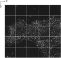
- a diagram for explaining switching between the first displacement sensor and the second displacement sensor Diagram for explaining an example of timing of auto focus control Diagram for explaining the positional relationship between the culture vessel and the first and second displacement sensors in the Z direction A diagram showing an example of a phase difference image of each observation position in the well Flow chart showing processing performed in the first embodiment Flow chart showing processing performed in the first embodiment Figure showing a display example of the evaluation results integrated by well Flow chart showing processing performed in the second embodiment
- FIG. 1 is a view showing a schematic configuration of a microscope apparatus 10 in the microscope observation system of the first embodiment.
- the microscope device 10 captures a phase difference image of cultured cells to be observed.
- the microscope apparatus 10 includes a white light source 11 that emits white light, a condenser lens 12, a slit plate 13, an imaging optical system 14, an imaging optical system drive unit 15, and an imaging device. 16 and a detection unit 18.
- the slit plate 13 is provided with a ring-shaped slit for transmitting white light to a light shielding plate for shielding white light emitted from the white light source 11, and the white light passes through the slit to form a ring shape.
- Illumination light L is formed.
- FIG. 2 is a diagram showing a detailed configuration of the imaging optical system 14.
- the imaging optical system 14 includes a phase difference lens 14 a and an imaging lens 14 d.
- the phase difference lens 14a includes an objective lens 14b and a phase plate 14c.
- the phase plate 14 c has a phase ring formed on a transparent plate transparent to the wavelength of the illumination light L.
- the size of the slit of the slit plate 13 described above is in a conjugate relationship with the phase ring of the phase plate 14 c.
- phase film for shifting the phase of the incident light by 1 ⁇ 4 wavelength and a light reducing filter for reducing the incident light are formed in a ring shape.
- the direct light incident on the phase ring is shifted in phase by 1 ⁇ 4 wavelength and is weakened in brightness by passing through the phase ring.
- most of the diffracted light diffracted by the object of observation passes through the transparent plate of the phase plate 14c, and its phase and brightness do not change.
- the phase difference lens 14a having the objective lens 14b is moved in the optical axis direction of the objective lens 14b by the imaging optical system drive unit 15 shown in FIG.
- the optical axis direction of the objective lens 14b and the Z direction are the same direction.
- the autofocus control is performed by the movement of the phase difference lens 14 a in the Z direction, and the contrast of the phase difference image captured by the imaging device 16 is adjusted.
- the magnification of the phase difference lens 14a may be changed.
- the phase difference lens 14a or the imaging optical system 14 having different magnifications may be configured to be exchangeable.
- the replacement of the phase difference lens 14a or the imaging optical system 14 may be performed automatically or may be performed manually by the user.
- the imaging optical system drive unit 15 includes an actuator such as a piezoelectric element, for example, and drives based on a control signal output from an autofocus control unit 21 described later.
- the imaging optical system drive unit 15 is configured to pass the phase difference image that has passed through the phase difference lens 14a as it is. Further, the configuration of the imaging optical system drive unit 15 is not limited to the piezoelectric element, as long as the retardation lens 14a can be moved in the Z direction, and other known configurations can be used.
- the imaging lens 14 d receives the phase difference image that has passed through the phase difference lens 14 a and the imaging optical system drive unit 15, and forms an image on the imaging element 16.
- the imaging element 16 captures a phase difference image formed by the imaging lens 14d.
- a charge-coupled device (CCD) image sensor, a complementary metal-oxide semiconductor (CMOS) image sensor, or the like is used.
- CMOS complementary metal-oxide semiconductor
- an imaging device an imaging device provided with a RGB (Red Green Blue) color filter may be used, or a monochrome imaging device may be used.
- the detection unit 18 detects the position in the Z direction (vertical direction) of the culture container 50 installed on the stage 51.
- the detection unit 18 includes a first displacement sensor 18a and a second displacement sensor 18b.
- the first displacement sensor 18a and the second displacement sensor 18b are provided side by side in the X direction shown in FIG. 1 with the phase difference lens 14a interposed therebetween.
- the first displacement sensor 18a and the second displacement sensor 18b in the present embodiment are laser displacement meters, and the culture vessel 50 is irradiated with laser light, and the reflected light is detected to detect Z on the bottom of the culture vessel 50. Detect the position of the direction.
- the bottom of the culture vessel 50 is the interface between the bottom of the culture vessel 50 and the cells to be observed, that is, the observation target installation surface.
- Position information representing the position of the culture vessel 50 in the Z direction detected by the detection unit 18 is output to the autofocus control unit 21, and the autofocus control unit 21 generates an imaging optical system based on the input position information.
- the drive unit 15 is controlled to perform autofocus control. The detection of the position of the culture container 50 by the first displacement sensor 18a and the second displacement sensor 18b and the autofocus control by the autofocus control unit 21 will be described in detail later.
- a stage 51 is provided between the slit plate 13 and the phase difference lens 14 a and the detection unit 18. On the stage 51, a culture container 50 containing cells to be observed is installed.
- a petri dish, a dish, a well plate or the like can be used as the culture container 50.
- pluripotent stem cells such as iPS cells and ES cells, nerves induced to differentiate from stem cells, cells of skin, myocardium and liver, skins removed from human body, retina, There are myocardium, blood cells, nerve and organ cells, etc.
- the stage 51 is moved in the X direction and the Y direction orthogonal to each other by a horizontal direction drive unit 17 (see FIG. 4) described later.
- the X direction and the Y direction are directions orthogonal to the Z direction, and are directions orthogonal to each other in the horizontal plane.
- the X direction is the main scanning direction
- the Y direction is the sub scanning direction.
- FIG. 3 shows an example of the stage 51. As shown in FIG. At the center of the stage 51, a rectangular opening 51a is formed. The culture vessel 50 is placed on a member forming the opening 51a, and a phase difference image of cells in the culture vessel 50 is configured to pass through the opening 51a.
- FIG. 4 is a block diagram showing the configuration of the imaging control apparatus of the first embodiment.
- photography control apparatus 20 is shown.
- the imaging control apparatus 20 controls the entire microscope apparatus 10, and includes an autofocus control unit 21, a scan control unit 22, a processing control unit 23, and a display control unit 24.
- the imaging control device 20 is configured of a computer provided with a central processing unit, a semiconductor memory, a hard disk and the like, and an embodiment of the observation device control program of the present invention is installed on the hard disk. Then, the central control unit executes this observation device control program, whereby the autofocus control unit 21, the scan control unit 22, the processing control unit 23, and the display control unit 24 shown in FIG. 4 function.
- the autofocus control unit 21 controls the imaging optical system drive unit 15 based on the position information of the culture container 50 in the Z direction detected by the detection unit 18 as described above. Then, the objective lens 14 b of the imaging optical system 14 is moved in the optical axis direction by the drive of the imaging optical system drive unit 15, and autofocus control is performed.
- the scan control unit 22 drives and controls the horizontal drive unit 17 to move the stage 51 in the X direction and the Y direction.
- the horizontal drive unit 17 is configured of an actuator having a piezoelectric element or the like.
- FIG. 5 is a diagram showing the scanning position of the observation position in the culture container 50 by a solid line M.
- a well plate having six wells W is used as the culture vessel 50.
- the imaging optical system 14 moves along the solid line M from the scanning start point S to the scanning end point E. That is, the observation position on the culture vessel 50 by the imaging optical system 14 is moved in the Y direction (downward in FIG. 5) after being scanned in the positive direction (rightward in FIG. 5) in the X direction. It is scanned in the negative direction (left direction in FIG. 5). Then, the observation position is moved in the Y direction again and scanned in the positive direction again. As described above, the imaging optical system 14 two-dimensionally scans the inside of the culture container 50 by repeatedly performing reciprocating movement in the X direction and movement in the Y direction.
- FIGS. 6 and 7 show the positions of the imaging optical system 14, the first displacement sensor 18a and the second displacement sensor 18b, and the culture container 50 when the observation position R is at an arbitrary position in the culture container 50. It is the figure which showed the relationship.
- a first displacement sensor 18a and a second displacement sensor 18b are provided side by side in the X direction with the imaging optical system 14 interposed therebetween. Then, the culture vessel 50 is scanned in a two-dimensional manner as described above, in which case the moving direction (that is, the main scanning direction) is reached before a certain observation position R in the culture vessel 50 reaches the imaging optical system 14 The position in the Z direction at the observation position R of the culture vessel 50 is detected prior to the imaging optical system 14 in. Specifically, when the observation position R moves in the arrow direction (left direction in FIG. 6) shown in FIG.
- the main scanning direction of the first displacement sensor 18a and the second displacement sensor 18b The position in the Z direction at the observation position R of the culture vessel 50 is detected by the first displacement sensor 18a preceding the imaging optical system 14 in. In FIG. 6, the first displacement sensor 18a is hatched. Then, when the observation position R moves to the position of the imaging optical system 14, the position information of the culture vessel 50 in the Z direction detected in advance is used to perform autofocus control, and imaging of the phase difference image is performed. To be done. Further, in the present embodiment, the position in the Z direction at the observation position R of the culture vessel 50 is also detected by the second displacement sensor 18b following the imaging optical system 14 in the main scanning direction after imaging the phase difference image. Be done. In this case, the detection position by the first displacement sensor 18a corresponds to the first position, and the detection position by the second displacement sensor 18b corresponds to the second position.
- the position in the Z direction at the observation position R of the culture container 50 is also detected by the first displacement sensor 18a following the imaging optical system 14 in the main scanning direction. Ru.
- the detection position by the second displacement sensor 18 b corresponds to the first position
- the detection position by the first displacement sensor 18 a corresponds to the second position.
- Position information representing the position of the culture container 50 in the direction detected by the first and second displacement sensors 18 a and 18 b is associated with the XY coordinates of each observation position R, and the imaging control device 20 It is stored in a semiconductor memory or a hard disk (not shown).
- the detection of the position of the culture container 50 in the Z direction using the first displacement sensor 18a and the detection of the position of the culture container 50 in the Z direction using the second displacement sensor 18b are changes in the main scanning direction.
- the autofocus control unit 21 controls the drive of the imaging optical system drive unit 15 based on the position information of the culture vessel 50 in the Z direction detected prior to the imaging optical system 14 as described above. Perform auto focus control. Specifically, in the autofocus control unit 21, the relationship between the position information of the culture vessel 50 in the Z direction and the movement amount of the imaging optical system 14 in the optical axis direction is set in advance. The autofocus control unit 21 obtains the amount of movement of the imaging optical system 14 in the direction of the optical axis based on the input positional information of the culture vessel 50 in the Z direction, and generates a control signal corresponding to the amount of movement. It outputs to the system drive unit 15. The imaging optical system drive unit 15 is driven based on the input control signal, whereby the imaging optical system 14 (the objective lens 14b) is moved in the optical axis direction, and according to the position of the culture vessel 50 in the Z direction. Focus adjustment is performed.
- the detection timing of the position of the culture vessel 50 at each observation position R and the phase difference image The imaging timing is temporally shifted. Therefore, the movement of the imaging optical system 14 (the objective lens 14b) in the Z direction, that is, the autofocus control, is performed after the detection of the position of the culture vessel 50 by the first displacement sensor 18a or the second displacement sensor 18b. , Is performed until the observation position R reaches the detection position.
- the position of the culture vessel 50 in the Z direction may shift due to some factor until the observation position R reaches the detection position. And the focus position may shift.
- the timing of the autofocus control be immediately before the observation position R reaches the detection position, and at which the imaging of the phase difference image at the detection position is in time.
- “immediately before the observation position R reaches the detection position” is, for example, as shown in FIG. 8, the observation position R sequentially moves in the X direction, and the detection position by the detection unit 18 is the position of Pd indicated by oblique lines.
- the observation position R be from the point of time when the position Pr of the observation position R adjacent to the detection position Pd passes to the point at which the detection position Pd is reached.
- the autofocus control may be performed when the observation position R reaches the detection position Pd.
- the autofocus using the position information of the detection position from the detection timing by the first or second displacement sensor 18a, 18b so that the timing of the autofocus control becomes the desired timing as described above.
- the time until the timing of control is set in advance.
- the above-mentioned preset time may be changed according to the change of the moving speed of the stage 51.
- the first displacement sensor 18a is moved by moving the first displacement sensor 18a or the second displacement sensor 18b in the X direction.
- the distance between the second displacement sensor 18 b and the imaging optical system 14 may be changed.
- the first displacement sensor 18 a and the second displacement sensor 18 b are provided side by side in the X direction with the imaging optical system 14 interposed therebetween, and the culture container 50 is When detecting the position, in order to perform position detection of the culture container 50 and imaging of the phase difference image in the entire range of the culture container 50, as shown in FIG. It is necessary to move the imaging optical system 14, the first displacement sensor 18a, and the second displacement sensor 18b relatively to the ranges R1 and R2. Then, it is necessary to secure at least a distance between the first displacement sensor 18a and the imaging optical system 14 in the X direction as the width in the X direction of the range R1, and at least a second width in the X direction of the range R2.
- the width in the X direction of the range R1 is preferably the distance between the first displacement sensor 18a and the imaging optical system 14 in the X direction, and the width in the X direction of the range R2 is the second displacement sensor 18b. It is desirable that the distance between the lens and the imaging optical system 14 be in the X direction.
- the moving speed of the stage 51 in the X direction is constant, it is possible to rapidly control the speed to a constant speed with almost no acceleration region, but when such control is performed, The liquid level of the culture solution or the like contained in the culture vessel 50 together with the cells may shake, which may lead to the deterioration of the image quality of the phase difference image. In addition, the same problem may occur when stopping the stage 51.
- the range R1 and the range R2 shown in FIG. 5 are set in the acceleration / deceleration region of the movement of the stage 51 in the X direction.
- the observation position R is scanned at a constant speed in the range of the culture vessel 50 without unnecessarily expanding the scanning range.
- the fluctuation of the liquid level of the culture solution as described above can also be suppressed.
- the processing control unit 23 controls the position in the Z direction of the culture container 50 detected by the first displacement sensor 18 a and the culture detected by the second displacement sensor 18 b at the target observation position R0 to be processed.
- the absolute value of the difference between the position of the container 50 and the Z direction is calculated.
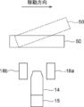
- FIG. 9 is a view showing the positional relationship between the culture container 50 and the first and second displacement sensors 18a and 18b in the Z direction.
- the culture container 50 is assumed to move to the right.
- the position of the culture vessel 50 in the Z direction is detected by the second displacement sensor 18b for autofocus control, and then the Z direction of the culture vessel 50 is detected by the first displacement sensor 18a. Position is detected.
- the second displacement is caused by vibration or the influence of the accuracy of the horizontal drive unit 17 or the like.
- the culture vessel 50 may be tilted as shown by a broken line in FIG.
- the position of the culture container 50 in the Z direction detected by the second displacement sensor 18b is different from the position of the culture container 50 in the Z direction detected by the first displacement sensor 18a.
- an absolute value of a difference value between the position in the Z direction of the culture vessel 50 detected by the first displacement sensor 18a and the position in the Z direction of the culture vessel 50 detected by the second displacement sensor 18b. Will grow.
- the observation position R is automatically detected based on the position of the culture vessel 50 in the Z direction detected by the displacement sensor preceding the imaging optical system 14 at the time of scanning. Even when the focus control is performed, the image may not be in focus and the image at the observation position R may be blurred.
- the processing control unit 23 controls processing for observation at the target observation position R0. Specifically, at least one of imaging of a target observation position and image processing on an image of the target observation position is controlled. Hereinafter, control of photographing and image processing will be described.
- the processing control unit 23 rephotographs the target observation position R0 determined to have the absolute value of the difference value larger than the threshold value Th1.
- the absolute value of the difference value is larger than the threshold value Th1
- the process control unit 23 instructs the microscope device 10 to appropriately focus on the target observation position R0, and rephotographs the target observation position R0.
- the position information of the culture vessel 50 in the Z direction is stored in association with the XY coordinates of the observation position R as described above. Therefore, the position of the target observation position R0 can be easily identified.
- the process control unit 23 may notify that the target observation position R0 is highly likely to be blurred when it is determined that the calculated absolute value of the difference value is larger than the threshold value Th1. .
- the display control unit 24 displays on the display device 30 a composite image obtained by connecting and combining a plurality of phase difference images, but the composite displayed on the display device 30 In the image, the notification may be performed by emphasizing and displaying the phase difference image of the observation area in which the absolute value of the calculated difference value is larger than the threshold value Th1.
- the phase difference image of the area may be emphasized and displayed by providing a frame such as red in the area surrounded by the dotted line, blinking the frame, or blinking the area.
- notification may be made by text or voice.
- the processing control unit 23 performs sharpness enhancement processing on the phase difference image at the target observation position R0. Specifically, the degree of emphasis of sharpness is changed according to the magnitude of the absolute value of the calculated difference value to perform the sharpness emphasis process.
- a table in which the values of various difference values are associated with the degree of emphasis of sharpness is stored in the hard disk of the imaging control apparatus 20. The process control unit 23 refers to this table to acquire the degree of sharpness enhancement according to the value of the difference value, and performs the sharpness enhancement process on the phase difference image at the target observation position R0.
- the display control unit 24 combines the phase difference images of the respective observation positions R captured by the microscope device 10 to generate one combined phase difference image, and the combined phase difference thereof.
- An image is displayed on the display device 30.
- combination phase difference image is produced
- sharpness enhancement processing is performed on the phase difference image at the observation position, a synthesized phase difference image is generated using the processed phase difference image.
- the display device 30 displays the composite phase difference image generated by the display control unit 24 as described above, and includes, for example, a liquid crystal display or the like.
- the display device 30 may be configured by a touch panel and used as the input device 40.
- the input device 40 includes a mouse, a keyboard, and the like, and receives various setting inputs from the user.
- the input device 40 receives setting inputs such as, for example, an instruction to change the magnification of the phase difference lens 14 a and an instruction to change the moving speed of the stage.
- 11 and 12 are flowcharts showing the processing performed in the first embodiment.
- the culture vessel 50 containing cells to be observed is placed on the stage 51 (step ST10).
- the stage 51 is moved, the imaging optical system 14 is set at the position of the scanning start point S shown in FIG. 5, and the scanning of the culture vessel 50 is started (step ST12).
- position detection of the culture container 50 in the Z direction is performed prior to imaging at each observation position R, and when the observation position R reaches the detection position, Imaging of the phase difference image is performed.
- the position detection of the culture vessel 50 and the imaging of the phase difference image are performed while scanning the culture vessel 50, and the imaging of the phase difference image at a certain observation position R and the observation position R before the observation position R are performed.
- the position detection of the corresponding culture vessel 50 in the Z direction is performed in parallel.
- the position of the culture container 50 in the Z direction is detected by the first displacement sensor 18a (step ST14), and the detection is performed Position information is acquired by the autofocus control unit 21.
- the autofocus control unit 21 calculates the amount of movement of the objective lens 14b based on the acquired position information of the culture container 50 in the Z direction (step ST16), and the amount of movement of the objective lens 14b corresponds to the detection position of the culture container 50. It is stored in association with the position on the XY coordinates (step ST18). At this time, the position in the Z direction of the culture vessel 50 detected by the first displacement sensor 18a and the second displacement sensor 18b is also correlated with the position on the XY coordinates of the detection position of the culture vessel 50. Are stored.
- the observation position R moves toward the position at which the position detection of the culture container 50 has been performed by the first displacement sensor 18a (step ST20).
- the autofocus control unit 21 acquires the movement amount of the objective lens 14b stored immediately before the observation position R reaches the position where the position detection of the culture vessel 50 is performed, and performs the auto based on the acquired movement amount. Focus control is performed (steps ST22 and ST24). That is, the autofocus control unit 21 controls the drive of the imaging optical system drive unit 15 based on the movement amount stored in advance, and moves the objective lens 14b in the Z direction.
- step ST26 imaging of the phase difference image is performed (step ST26).
- the phase difference image at the observation position R is output from the imaging element 16 to the display control unit 24 and stored.
- the position detection of the culture container 50 by the displacement sensor preceding in the scanning direction with respect to each observation position R is performed in parallel. To be done.
- step ST28 the target observation position R0 is moved to the position of the second displacement sensor 18b, and the second displacement sensor 18b detects the position of the culture container 50 in the Z direction at the target observation position R0.
- the second displacement sensor 18b detects the position of the culture container 50 in the Z direction at the target observation position R0.
- step ST30 YES
- the displacement sensor used for the autofocus control from the first displacement sensor 18a to the second displacement sensor It switches to 18b (step ST32).
- Step ST34 the observation position R moves in the X direction again, and the above-described position detection of the culture container 50 and the imaging of the phase difference image are sequentially performed. (Steps ST14 to ST28).
- the displacement sensor to be used is switched each time the observation position R moves to the range R1, R2 of the acceleration / deceleration region, and the processing from step ST14 to step ST28 is repeated until all scanning is completed. Then, when the observation position R reaches the position of the scanning end point E shown in FIG. 5, all the scanning ends (step ST34, YES).
- the processing control unit 23 determines the position of the culture vessel 50 in the Z direction detected by the first displacement sensor 18a and the second displacement for the target observation position R0 among the plurality of observation positions.
- the absolute value of the difference value with the position of the culture vessel 50 in the Z direction detected by the sensor 18 b is calculated. (Step ST36). Then, it is determined whether the absolute value of the calculated difference value is larger than the threshold value Th1 (step ST38).
- step ST38 the process control unit 23 controls the process for observing the target observation position R0 (step ST40). Specifically, re-imaging at the target observation position R0, notification that the phase difference image at the target observation position R0 is likely to be blurred, or sharpness enhancement processing on the phase difference image at the target observation position R0 is performed. If step ST38 is negative, the process proceeds to step ST42.
- steps ST36 to ST40 is repeated until the determination of all the observation positions R is completed (ST42, NO).
- the display control unit 24 combines all the phase difference images and combines them to generate a combined phase difference image, and generates the combined phase difference image Are displayed on the display device 30 (step ST44), and the process is ended.
- the target observation detected by the displacement sensor preceding the target observation position R0 in the main scanning direction before the imaging optical system 14 reaches the target observation position in the culture vessel 50 The autofocus control is performed based on the first position in the vertical direction of the culture container 50 at the position R0. Therefore, autofocus control can be performed at high speed.
- the processing for observation at the target observation position R0 is controlled. . Therefore, even if the vertical position of the culture vessel 50 changes due to vibration or the like after detection by the displacement sensor preceding in the main scanning direction, the change can be detected by the displacement sensor following in the main scanning direction. . Therefore, it is possible to use a phase difference image at the target observation position R0 which is controlled for observation, and thereby, it is possible to perform accurate and highly reliable evaluation on the observation target.
- the configuration of a microscope observation system using the second embodiment of the imaging control apparatus, method and program of the present invention is the same as the configuration of the microscope observation system using the first embodiment shown in FIG. Only the processing performed by the processing control unit 23 is different. Therefore, the description of the configuration is omitted.
- the processing for observation at the target observation position R0 is controlled. Specifically, at least one of imaging of a target observation position and image processing on an image of the target observation position is controlled.
- the processing control unit 23 further evaluates the state of the cells included in the phase difference image at the target observation position R0, and the calculated absolute value of the difference value is larger than the threshold value Th1.
- the process control unit 23 controls the process for observation at the target observation position R0 by evaluating the state of the cells included in the phase difference image for each observation position R. Assessing the state of cells means, for example, evaluating whether the cells included in the phase contrast image are undifferentiated cells or differentiated cells, counting the number of cells for each cell type during co-culture, Evaluating the proportion of undifferentiated cells and differentiated cells contained in the phase contrast image, evaluating the degree of growth of cells or cell colonies, or evaluating the reduction rate of cancer cells by anticancer drugs Say. However, as evaluation of the state of a cell, not only these but other evaluation may be sufficient.
- the processing control unit 23 in the second embodiment includes a blurred phase difference image (absolute value of difference value> Th1, including a phase difference image having a high possibility of being blurred below) and an unblurred phase difference image ( Evaluate the state of cells by different evaluation methods with the absolute value of the difference value ⁇ Th1 (including the phase difference image with high possibility of blurring below). Specifically, the processing control unit 23 evaluates the phase difference image that is not blurred using the feature amount that indicates the state of the cells included in the phase difference image, and for the phase difference image that is blurred, the image Evaluate using feature quantities.
- phase difference image that is not blurred
- an image of a cell included in the phase difference image or an image of a fine structure of a cell such as a nucleus or a nucleolus can be recognized with high accuracy. For this reason, it is possible to obtain an evaluation result excellent in biological explanatory power by performing evaluation using the feature amount indicating the state of the cell as described above. Conversely speaking, it can be said that the evaluation method using the feature quantity indicating the state of the cell is a weak evaluation method against blurring (deterioration) relatively.
- the feature quantities that indicate the state of the cell include the feature quantity of the individual cell state, the feature quantity of the nucleolus contained in the cell, the feature quantity of the white streaks, the feature quantity of the nucleus contained in the cell and the NC of the cell At least one of the ratios can be used.
- the characteristic quantities of individual cell states include, for example, the number of cells, the density of cells, the growth rate of cells, and the degree of circularity of cells, but the individual cells included in the phase contrast image were recognized and recognized Other feature quantities may be used as long as they are feature quantities calculated based on cells.
- a method of recognizing cells included in the phase difference image for example, a method of detecting an edge of an image of a cell, detecting using a pattern matching process, or detecting using a discriminator generated by machine learning
- other known techniques can be used.
- the degree of circularity of cells undifferentiated cells have relatively high degree of circularity, but differentiated cells have, for example, an elongated shape and relatively low degree of circularity.
- the method for evaluating whether a differentiated cell or an undifferentiated cell is not limited to this, and other known methods can be used.
- dendrite length can be used as a feature that indicates the state of individual cells. By using the dendrite length, it is possible to assess the degree of neural cell growth.
- the characteristic quantities of nuclei or nuclear bodies contained in cells include, for example, the number of nuclei or nuclear bodies, the density of nuclei or nuclear bodies, and the increase rate of nuclei or nuclear bodies, etc.
- the characteristic quantities of nuclei or nuclear bodies contained in cells include, for example, the number of nuclei or nuclear bodies, the density of nuclei or nuclear bodies, and the increase rate of nuclei or nuclear bodies, etc.
- it is a feature that recognizes nuclei or nucleolus contained in an image and is calculated based on the recognized nuclei or nucleolus, other features may be used.
- edge detection, detection by pattern matching, detection using a discriminator, and the like can be used as in the method of cell recognition.
- the feature quantities of white streaks include, for example, the total area of white streaks, the density of white streaks, and the distribution state of white streaks, and the white streaks recognized in the phase difference image are recognized and recognized. Other feature quantities may be used as long as they are feature quantities calculated based on the above.
- a phase difference image may be binarized and white streaks may be extracted by threshold processing, detected by using pattern matching processing, or generated by machine learning. Although there is a method of detecting using a discriminator, other known methods can be used.
- the differentiation degree or the undifferentiated degree of the cell colony, the growth degree of the cell colony, etc. can be evaluated based on the characteristic amount of the white streak.
- the NC ratio of cells is the nuclear / cytoplasmic area ratio.
- the NC ratio can be determined by using the cytoplasmic and nuclear detectors.
- the cytoplasm generally has a gray and flat appearance, whereas the nuclei are relatively round and contain structures such as nucleoli internally. Therefore, a cytoplasmic region and a nuclear region are obtained by creating each detector by machine learning and applying it to the phase difference image.
- the NC ratio can be calculated by calculating the ratio of the area of the cytoplasmic region to the nuclear region obtained in this manner.
- the NC ratio may be calculated in cell colony units, or may be calculated in a previously designated region.
- the evaluation accuracy is improved by evaluating using the image feature amount of the phase difference image itself rather than using the feature amount indicating the state of individual cells as in the phase difference image that is not blurred. It can be said that the evaluation method using the image feature amount is relatively stronger against blurring (deterioration) than the evaluation method using the feature amount indicating the state of the cell described above.
- the image feature amount used when evaluating a blurred phase difference image is the feature amount of the captured image itself, and specifically, the average brightness of the phase difference image, the variance of the brightness of the phase difference image, the phase difference Use the difference between the maximum value and the minimum value of the brightness of the image, the contrast of the phase difference image, the entropy of the phase difference image, the spatial frequency distribution of the phase difference image, the directivity of the phase difference image, the Zernike features of the phase difference image, etc. Can.
- the relationship between the image feature amount and the evaluation result corresponding to the image feature amount is obtained in advance by experiment or the like.
- An evaluation result may be obtained based on the image feature amount of the phase difference image and the above relationship.
- the relationship between the image feature amount and the evaluation result corresponding to the image feature amount is learned using, for example, machine learning to generate an evaluator, and the image feature amount of the phase difference image is input to the evaluator.
- the evaluation result may be obtained by
- the process control unit 23 of the second embodiment integrates the evaluation results of the phase difference image of each observation area in the well, and calculates the evaluation result for the well. That is, the evaluation result on a well basis is calculated.
- the evaluation result in the well unit (container unit), it can be managed in the well unit at the time of passage or shipping of cells.
- the cell state is evaluated by different evaluation methods for the phase difference image that is blurred and the phase difference image that is not blurred, so the phase difference image of each observation region is appropriate
- the evaluation results can be evaluated by the following evaluation methods, and evaluation results can be obtained more accurately and reliably as the evaluation results on a well basis.
- the ratio of differentiated cells in a well to the undifferentiated cells by calculating the average value of the ratio of differentiated cells and the ratio of undifferentiated cells contained in the phase contrast image of each observation area in the well The percentage of cells may be determined.
- the average value of the growth degree of each observation area may be determined as the degree of growth per well.
- the proportion of the number of observation areas having the growth degree equal to or more than the threshold value among all the observation areas in the well may be calculated, and the proportion may be determined as the growth degree of the well unit.
- the evaluation result in the well unit may be "good", and if it is less than the threshold value, the evaluation result in the well unit may be "poor" .
- the evaluation result of the observation area whose growth degree is equal to or more than the threshold is "good”
- the evaluation result of the observation area less than the threshold is “bad”
- the evaluation result included in the well is "good”
- the evaluation result in well units may be “good”
- the evaluation result in well units may be “bad”.
- the display control unit 24 causes the display device 30 to display the evaluation result of the process control unit 23. Specifically, in the second embodiment, as described above, since the evaluation result in the well unit is calculated in the process control unit 23, the display control unit 24 displays the evaluation result in the well unit. Display on 30 FIG. 13 shows an example in which the percentage of differentiated cells and the percentage of undifferentiated cells in a well unit are calculated as a result of integrated evaluation when a 6-well plate is used.
- FIG. 14 is a flowchart showing the process performed in the second embodiment.
- the same processes as in the first embodiment are performed until step ST34 in the first embodiment. Therefore, FIG. 14 shows only the process after step ST34 in the first embodiment.
- the processing control unit 23 determines the position of the culture vessel 50 in the Z direction detected by the first displacement sensor 18a for the target observation position R0 among the plurality of observation positions, and the first The absolute value of the difference value with the position of the culture container 50 in the Z direction detected by the two displacement sensors 18b is calculated (step ST50). Then, it is determined whether the absolute value of the calculated difference value is larger than the threshold value Th1 (step ST52).
- step ST52 the process control unit 23 evaluates the phase difference image at the target observation position R0 using the evaluation method of the blurred phase difference image (step ST54). Specifically, an image feature amount is calculated for the phase difference image, and the state of cells included in the phase difference image is evaluated using the image feature amount.
- step ST52 when step ST52 is negative, the process control unit 23 evaluates the phase difference image at the target observation position R0 using the evaluation method of the unblurred phase difference image (step ST56). Specifically, for the phase difference image, a feature amount indicating the state of the cell is calculated, and using the feature amount, the state of the cell included in the phase difference image is evaluated.
- step ST50 to ST56 is repeated until the evaluation of the phase difference image of all the observation positions is completed (step ST58, NO).
- step ST58, YES the processing control unit 23 integrates the evaluation results of the phase difference image of each observation position in wells and acquires the evaluation results in wells.
- step ST60 the display control unit 24 generates a synthesized phase difference image using the phase difference image of each observation position, displays the synthesized phase difference image on the display device 30, and displays the integrated evaluation result in units of wells.
- Step ST62 the process ends.
- the evaluation method of the phase difference image is changed according to whether or not the absolute value of the calculated difference value is larger than the threshold value Th1.
- the evaluation was made using different evaluation methods for the blurred phase difference image and the unblurred phase difference image. Therefore, the phase difference image can be evaluated by the evaluation method suitable for the phase difference image, and more accurate and highly reliable evaluation can be performed.
- the processing control unit 23 integrates the phase difference images of the respective observation positions in the well to calculate the evaluation result in the well unit.
- weighting may be added to the evaluation result of the blurred phase difference image and the evaluation result of the non-blurred phase difference image.
- the weighting is preferably set so that the weighting added to the evaluation result of the unblurred phase difference image is larger than the weighting added to the evaluation result of the blurred phase difference image. This is because it is considered that the phase difference image which is not blurred is more accurate in the evaluation result.
- a weight smaller than 0.5 is applied to the growth degree of the observation area of the blurred phase difference image.
- a weighting of 0.5 or more may be added to the degree of growth of the observation area of the non-blurred phase difference image.
- the evaluation method when the calculated absolute value of the difference value is larger than the threshold value Th1, the evaluation method is changed by excluding the phase difference image of the observation position R from the evaluation target. May be In this case, when calculating the evaluation result, the phase difference image of the observation position R is excluded from the evaluation targets.
- the stage 51 is moved.
- the stage 51 may be fixed, and the imaging optical system 14 and other configurations relating to imaging of a phase difference image may be moved.
- both of the stage 51 and the imaging optical system 14 and other configurations relating to imaging of a phase difference image may be moved.
- the above embodiment is an application of the present invention to a phase contrast microscope, but the present invention is not limited to a phase contrast microscope, and may be applied to other microscopes such as a differential interference microscope and a bright field microscope. It is also good.
- the above determination may be performed while acquiring the phase difference image of each observation area.
Landscapes
- Physics & Mathematics (AREA)
- General Physics & Mathematics (AREA)
- Optics & Photonics (AREA)
- Chemical & Material Sciences (AREA)
- Analytical Chemistry (AREA)
- Engineering & Computer Science (AREA)
- Multimedia (AREA)
- Pathology (AREA)
- General Health & Medical Sciences (AREA)
- Immunology (AREA)
- Biochemistry (AREA)
- Life Sciences & Earth Sciences (AREA)
- Health & Medical Sciences (AREA)
- Computer Vision & Pattern Recognition (AREA)
- Mathematical Physics (AREA)
- Theoretical Computer Science (AREA)
- Spectroscopy & Molecular Physics (AREA)
- Microscoopes, Condenser (AREA)
- Automatic Focus Adjustment (AREA)
- Investigating Or Analysing Materials By Optical Means (AREA)
- Studio Devices (AREA)
Abstract
La présente invention concerne un dispositif, un procédé et un programme de commande d'imagerie qui permettent d'accélérer la commande de mise au point automatique et d'effectuer des évaluations plus précises et hautement fiables. Dans le cadre de la présente invention, une unité de commande de mise au point automatique (21) réalise une commande de mise au point automatique sur la base d'une première position de direction verticale d'un conteneur au niveau d'une position d'observation cible, la première position ayant été détectée par un capteur de déplacement qui précède la position d'observation cible dans une direction de balayage principale. Sur la base de la première position et d'une seconde position de direction verticale du conteneur au niveau de la position d'observation cible, la seconde position ayant été détectée par un capteur de déplacement qui se trouve après la position d'observation cible dans la direction de balayage principale, une unité de commande de traitement (23) commande le traitement à appliquer pour l'observation de la position d'observation cible.
Priority Applications (3)
| Application Number | Priority Date | Filing Date | Title |
|---|---|---|---|
| EP18852471.4A EP3677943A4 (fr) | 2017-08-29 | 2018-08-07 | Dispositif, procédé et programme de commande d'imagerie |
| JP2019539136A JP6704530B2 (ja) | 2017-08-29 | 2018-08-07 | 撮影制御装置、方法およびプログラム |
| US16/798,585 US20200192059A1 (en) | 2017-08-29 | 2020-02-24 | Imaging control apparatus, method, and program |
Applications Claiming Priority (2)
| Application Number | Priority Date | Filing Date | Title |
|---|---|---|---|
| JP2017163961 | 2017-08-29 | ||
| JP2017-163961 | 2017-08-29 |
Related Child Applications (1)
| Application Number | Title | Priority Date | Filing Date |
|---|---|---|---|
| US16/798,585 Continuation US20200192059A1 (en) | 2017-08-29 | 2020-02-24 | Imaging control apparatus, method, and program |
Publications (1)
| Publication Number | Publication Date |
|---|---|
| WO2019044424A1 true WO2019044424A1 (fr) | 2019-03-07 |
Family
ID=65526320
Family Applications (1)
| Application Number | Title | Priority Date | Filing Date |
|---|---|---|---|
| PCT/JP2018/029607 WO2019044424A1 (fr) | 2017-08-29 | 2018-08-07 | Dispositif, procédé et programme de commande d'imagerie |
Country Status (4)
| Country | Link |
|---|---|
| US (1) | US20200192059A1 (fr) |
| EP (1) | EP3677943A4 (fr) |
| JP (1) | JP6704530B2 (fr) |
| WO (1) | WO2019044424A1 (fr) |
Cited By (2)
| Publication number | Priority date | Publication date | Assignee | Title |
|---|---|---|---|---|
| JPWO2021009906A1 (fr) * | 2019-07-18 | 2021-01-21 | ||
| WO2021177004A1 (fr) * | 2020-03-05 | 2021-09-10 | ソニーグループ株式会社 | Dispositif de microscope, système d'acquisition d'image et procédé d'acquisition d'image |
Citations (7)
| Publication number | Priority date | Publication date | Assignee | Title |
|---|---|---|---|---|
| JPH10232342A (ja) * | 1997-02-19 | 1998-09-02 | Sankyo Seiki Mfg Co Ltd | 顕微鏡用オートフォーカス装置 |
| JP2003294419A (ja) * | 2002-03-29 | 2003-10-15 | Hitachi Kokusai Electric Inc | 微小寸法測定装置 |
| JP2003295065A (ja) * | 2002-03-29 | 2003-10-15 | Natl Inst Of Radiological Sciences | 顕微鏡装置 |
| JP2007218846A (ja) * | 2006-02-20 | 2007-08-30 | Omron Corp | 寸法計測方法、撮像装置、制御装置および寸法計測装置 |
| JP2010072017A (ja) * | 2008-09-16 | 2010-04-02 | Yokogawa Electric Corp | オートフォーカス装置 |
| WO2015133176A1 (fr) | 2014-03-05 | 2015-09-11 | 株式会社 日立ハイテクノロジーズ | Dispositif de microspectroscopie |
| JP2015230393A (ja) | 2014-06-05 | 2015-12-21 | キヤノン株式会社 | 撮像装置の制御方法および撮像システム |
Family Cites Families (4)
| Publication number | Priority date | Publication date | Assignee | Title |
|---|---|---|---|---|
| JP5589619B2 (ja) * | 2010-07-01 | 2014-09-17 | ソニー株式会社 | 情報処理装置、ステージうねり補正方法、プログラム |
| WO2013165576A1 (fr) * | 2012-05-02 | 2013-11-07 | Aperio Technologies, Inc. | Mise au point en temps réel en imagerie à balayage linéaire |
| JP6619315B2 (ja) * | 2016-09-28 | 2019-12-11 | 富士フイルム株式会社 | 観察装置および方法並びに観察装置制御プログラム |
| WO2019098150A1 (fr) * | 2017-11-17 | 2019-05-23 | 富士フイルム株式会社 | Dispositif et procédé d'observation, et programme de commande de dispositif d'observation |
-
2018
- 2018-08-07 JP JP2019539136A patent/JP6704530B2/ja active Active
- 2018-08-07 WO PCT/JP2018/029607 patent/WO2019044424A1/fr unknown
- 2018-08-07 EP EP18852471.4A patent/EP3677943A4/fr not_active Withdrawn
-
2020
- 2020-02-24 US US16/798,585 patent/US20200192059A1/en not_active Abandoned
Patent Citations (7)
| Publication number | Priority date | Publication date | Assignee | Title |
|---|---|---|---|---|
| JPH10232342A (ja) * | 1997-02-19 | 1998-09-02 | Sankyo Seiki Mfg Co Ltd | 顕微鏡用オートフォーカス装置 |
| JP2003294419A (ja) * | 2002-03-29 | 2003-10-15 | Hitachi Kokusai Electric Inc | 微小寸法測定装置 |
| JP2003295065A (ja) * | 2002-03-29 | 2003-10-15 | Natl Inst Of Radiological Sciences | 顕微鏡装置 |
| JP2007218846A (ja) * | 2006-02-20 | 2007-08-30 | Omron Corp | 寸法計測方法、撮像装置、制御装置および寸法計測装置 |
| JP2010072017A (ja) * | 2008-09-16 | 2010-04-02 | Yokogawa Electric Corp | オートフォーカス装置 |
| WO2015133176A1 (fr) | 2014-03-05 | 2015-09-11 | 株式会社 日立ハイテクノロジーズ | Dispositif de microspectroscopie |
| JP2015230393A (ja) | 2014-06-05 | 2015-12-21 | キヤノン株式会社 | 撮像装置の制御方法および撮像システム |
Non-Patent Citations (1)
| Title |
|---|
| See also references of EP3677943A4 * |
Cited By (4)
| Publication number | Priority date | Publication date | Assignee | Title |
|---|---|---|---|---|
| JPWO2021009906A1 (fr) * | 2019-07-18 | 2021-01-21 | ||
| WO2021009906A1 (fr) * | 2019-07-18 | 2021-01-21 | 株式会社島津製作所 | Procédé d'analyse d'images de cellules et dispositif d'analyse d'image de cellules |
| JP7342950B2 (ja) | 2019-07-18 | 2023-09-12 | 株式会社島津製作所 | 細胞画像解析方法および細胞画像解析装置 |
| WO2021177004A1 (fr) * | 2020-03-05 | 2021-09-10 | ソニーグループ株式会社 | Dispositif de microscope, système d'acquisition d'image et procédé d'acquisition d'image |
Also Published As
| Publication number | Publication date |
|---|---|
| EP3677943A1 (fr) | 2020-07-08 |
| JPWO2019044424A1 (ja) | 2020-02-27 |
| US20200192059A1 (en) | 2020-06-18 |
| EP3677943A4 (fr) | 2020-09-16 |
| JP6704530B2 (ja) | 2020-06-03 |
Similar Documents
| Publication | Publication Date | Title |
|---|---|---|
| WO2019181053A1 (fr) | Dispositif, procédé et programme de mesure de quantité de défocalisation et discriminateur | |
| WO2018003181A1 (fr) | Dispositif et procédé de photographie et programme de commande de photographie | |
| JP6704530B2 (ja) | 撮影制御装置、方法およびプログラム | |
| JP6824388B2 (ja) | 観察装置および観察制御方法並びに観察制御プログラム | |
| JP6619315B2 (ja) | 観察装置および方法並びに観察装置制御プログラム | |
| JP6861842B2 (ja) | 観察装置および方法並びに観察装置制御プログラム | |
| JP6549061B2 (ja) | 撮影装置および方法並びに撮影装置制御プログラム | |
| JP6698421B2 (ja) | 観察装置および方法並びに観察装置制御プログラム | |
| KR102261700B1 (ko) | 세포 화상 평가 장치 및 방법과, 프로그램 | |
| JPWO2020012825A1 (ja) | 画像生成装置、画像生成方法および画像生成プログラム | |
| JPWO2019202979A1 (ja) | 観察装置、観察装置の作動方法、及び観察制御プログラム | |
| WO2018061635A1 (fr) | Dispositif et procédé d'observation, et programme de commande de dispositif d'observation | |
| JP7133636B2 (ja) | フォーカス位置評価装置、方法、及びプログラム | |
| JP6848086B2 (ja) | 観察装置および方法並びに観察装置制御プログラム | |
| JP6812562B2 (ja) | 観察装置および方法並びに観察装置制御プログラム | |
| JP2020202748A (ja) | 撮影処理装置、撮影処理装置の制御方法および撮影処理プログラム | |
| WO2022113365A1 (fr) | Procédé de focalisation, dispositif d'observation, et programme | |
| WO2020066250A1 (fr) | Dispositif, procédé et programme d'évaluation de position de mise au point, et dispositif de détermination |
Legal Events
| Date | Code | Title | Description |
|---|---|---|---|
| 121 | Ep: the epo has been informed by wipo that ep was designated in this application |
Ref document number: 18852471 Country of ref document: EP Kind code of ref document: A1 |
|
| ENP | Entry into the national phase |
Ref document number: 2019539136 Country of ref document: JP Kind code of ref document: A |
|
| NENP | Non-entry into the national phase |
Ref country code: DE |
|
| ENP | Entry into the national phase |
Ref document number: 2018852471 Country of ref document: EP Effective date: 20200330 |