WO2019044424A1 - Imaging control device, method, and program - Google Patents
Imaging control device, method, and program Download PDFInfo
- Publication number
- WO2019044424A1 WO2019044424A1 PCT/JP2018/029607 JP2018029607W WO2019044424A1 WO 2019044424 A1 WO2019044424 A1 WO 2019044424A1 JP 2018029607 W JP2018029607 W JP 2018029607W WO 2019044424 A1 WO2019044424 A1 WO 2019044424A1
- Authority
- WO
- WIPO (PCT)
- Prior art keywords
- imaging
- target
- optical system
- observation position
- scanning direction
- Prior art date
Links
Images


Classifications
-
- G—PHYSICS
- G02—OPTICS
- G02B—OPTICAL ELEMENTS, SYSTEMS OR APPARATUS
- G02B7/00—Mountings, adjusting means, or light-tight connections, for optical elements
- G02B7/28—Systems for automatic generation of focusing signals
- G02B7/36—Systems for automatic generation of focusing signals using image sharpness techniques, e.g. image processing techniques for generating autofocus signals
-
- G—PHYSICS
- G02—OPTICS
- G02B—OPTICAL ELEMENTS, SYSTEMS OR APPARATUS
- G02B21/00—Microscopes
- G02B21/0004—Microscopes specially adapted for specific applications
- G02B21/002—Scanning microscopes
-
- G—PHYSICS
- G01—MEASURING; TESTING
- G01N—INVESTIGATING OR ANALYSING MATERIALS BY DETERMINING THEIR CHEMICAL OR PHYSICAL PROPERTIES
- G01N21/00—Investigating or analysing materials by the use of optical means, i.e. using sub-millimetre waves, infrared, visible or ultraviolet light
- G01N21/17—Systems in which incident light is modified in accordance with the properties of the material investigated
- G01N21/25—Colour; Spectral properties, i.e. comparison of effect of material on the light at two or more different wavelengths or wavelength bands
- G01N21/27—Colour; Spectral properties, i.e. comparison of effect of material on the light at two or more different wavelengths or wavelength bands using photo-electric detection ; circuits for computing concentration
-
- G—PHYSICS
- G01—MEASURING; TESTING
- G01N—INVESTIGATING OR ANALYSING MATERIALS BY DETERMINING THEIR CHEMICAL OR PHYSICAL PROPERTIES
- G01N21/00—Investigating or analysing materials by the use of optical means, i.e. using sub-millimetre waves, infrared, visible or ultraviolet light
- G01N21/17—Systems in which incident light is modified in accordance with the properties of the material investigated
- G01N21/41—Refractivity; Phase-affecting properties, e.g. optical path length
- G01N21/45—Refractivity; Phase-affecting properties, e.g. optical path length using interferometric methods; using Schlieren methods
-
- G—PHYSICS
- G02—OPTICS
- G02B—OPTICAL ELEMENTS, SYSTEMS OR APPARATUS
- G02B21/00—Microscopes
-
- G—PHYSICS
- G02—OPTICS
- G02B—OPTICAL ELEMENTS, SYSTEMS OR APPARATUS
- G02B21/00—Microscopes
- G02B21/0004—Microscopes specially adapted for specific applications
- G02B21/002—Scanning microscopes
- G02B21/0024—Confocal scanning microscopes (CSOMs) or confocal "macroscopes"; Accessories which are not restricted to use with CSOMs, e.g. sample holders
- G02B21/0036—Scanning details, e.g. scanning stages
-
- G—PHYSICS
- G02—OPTICS
- G02B—OPTICAL ELEMENTS, SYSTEMS OR APPARATUS
- G02B21/00—Microscopes
- G02B21/0004—Microscopes specially adapted for specific applications
- G02B21/002—Scanning microscopes
- G02B21/0024—Confocal scanning microscopes (CSOMs) or confocal "macroscopes"; Accessories which are not restricted to use with CSOMs, e.g. sample holders
- G02B21/0052—Optical details of the image generation
- G02B21/006—Optical details of the image generation focusing arrangements; selection of the plane to be imaged
-
- G—PHYSICS
- G02—OPTICS
- G02B—OPTICAL ELEMENTS, SYSTEMS OR APPARATUS
- G02B21/00—Microscopes
- G02B21/24—Base structure
- G02B21/241—Devices for focusing
-
- G—PHYSICS
- G02—OPTICS
- G02B—OPTICAL ELEMENTS, SYSTEMS OR APPARATUS
- G02B21/00—Microscopes
- G02B21/24—Base structure
- G02B21/26—Stages; Adjusting means therefor
-
- G—PHYSICS
- G02—OPTICS
- G02B—OPTICAL ELEMENTS, SYSTEMS OR APPARATUS
- G02B21/00—Microscopes
- G02B21/36—Microscopes arranged for photographic purposes or projection purposes or digital imaging or video purposes including associated control and data processing arrangements
-
- G—PHYSICS
- G02—OPTICS
- G02B—OPTICAL ELEMENTS, SYSTEMS OR APPARATUS
- G02B7/00—Mountings, adjusting means, or light-tight connections, for optical elements
- G02B7/28—Systems for automatic generation of focusing signals
Landscapes
- Physics & Mathematics (AREA)
- General Physics & Mathematics (AREA)
- Optics & Photonics (AREA)
- Chemical & Material Sciences (AREA)
- Analytical Chemistry (AREA)
- Engineering & Computer Science (AREA)
- Multimedia (AREA)
- Health & Medical Sciences (AREA)
- Immunology (AREA)
- Pathology (AREA)
- General Health & Medical Sciences (AREA)
- Life Sciences & Earth Sciences (AREA)
- Biochemistry (AREA)
- Computer Vision & Pattern Recognition (AREA)
- Mathematical Physics (AREA)
- Theoretical Computer Science (AREA)
- Spectroscopy & Molecular Physics (AREA)
- Microscoopes, Condenser (AREA)
- Automatic Focus Adjustment (AREA)
- Studio Devices (AREA)
- Investigating Or Analysing Materials By Optical Means (AREA)
Abstract
An imaging control device, method, and program that make it possible to accelerate autofocus control and to perform more accurate and highly reliable evaluations. According to the present invention, an autofocus control unit 21 performs autofocus control on the basis of a vertical-direction first position for a container at a target observation position, the first position having been detected by a displacement sensor that precedes the target observation position in a main scanning direction. On the basis of the first position and of a vertical-direction second position for the container at the target observation position, the second position having been detected by a displacement sensor that succeeds the target observation position in the main scanning direction, a processing control unit 23 controls processing that is for observation of the target observation position.
Description
本発明は、観察対象が収容された容器が設置されたステージと観察対象の像を結像させる結像光学系とを相対的に移動させることによって、観察対象全体の像を観察する撮影装置を制御するための撮影制御装置、方法およびプログラムに関するものである。
The present invention relates to a photographing apparatus for observing an image of the entire observation target by relatively moving a stage on which a container in which the observation target is accommodated is installed and an imaging optical system for forming an image of the observation target. The present invention relates to an imaging control apparatus, method, and program for controlling.
ES(Embryonic Stem)細胞およびiPS(Induced Pluripotent Stem)細胞等の多能性幹細胞は、種々の組織の細胞に分化する能力を備えたものであり、再生医療、薬の開発、および病気の解明等において応用が可能なものとして注目されている。
Pluripotent stem cells such as ES (Embryonic Stem) cells and iPS (Induced Pluripotent Stem) cells have the ability to differentiate into cells of various tissues, and they can be used in regenerative medicine, drug development, disease elucidation, etc. It is noted that it can be applied in
そして、ES細胞およびiPS細胞等の多能性幹細胞および分化誘導された細胞等を顕微鏡等で撮像し、その画像の特徴を捉えることで細胞の分化状態等を評価する方法が提案されている。
A method has been proposed in which pluripotent stem cells such as ES cells and iPS cells and cells induced to differentiate are imaged with a microscope or the like, and the characteristics of the image are captured to evaluate the differentiation state of the cells or the like.
一方、上述したように細胞を顕微鏡で撮像する際、高倍率な広視野画像を取得するため、いわゆるタイリング撮影を行うことが提案されている。具体的には、例えばウェルプレート等が設置されたステージを、結像光学系に対して移動させることによってウェル内の各観察位置を走査し、観察位置毎の画像を撮像した後、観察位置毎の画像を繋ぎ合わせて合成画像を生成する方法が提案されている。
On the other hand, when imaging cells with a microscope as described above, it is proposed to perform so-called tiling imaging in order to acquire a high magnification wide-field image. Specifically, for example, each observation position in the well is scanned by moving a stage on which a well plate or the like is installed with respect to the imaging optical system, and after an image for each observation position is captured, each observation position There has been proposed a method of joining together the images of to generate a composite image.
このようなタイリング撮影を行う場合には、培養容器内の各観察位置においてオートフォーカス制御を行うことによって、ボケの少ない高画質な画像を取得することが提案されている。ここで、オートフォーカス制御を行う場合、撮影時間の短縮の観点から、オートフォーカス制御を高速かつ高精度に行うことが重要である。
When performing such tiling imaging, it has been proposed to obtain a high-quality image with less blurring by performing autofocus control at each observation position in the culture vessel. Here, in the case of performing the autofocus control, it is important to perform the autofocus control at high speed and with high accuracy from the viewpoint of shortening the photographing time.
しかしながら、例えば培養容器として複数のウェルを有するウェルプレートを使用し、そのウェルプレート全体を結像光学系によって走査し、各観察位置についてオートフォーカス制御を行いながらタイリング撮影をする場合、各ウェルの底部の厚さは、製造上の誤差等によりウェル毎に異なる。また、培養容器のステージ上への設置の仕方によっては、ステージに対して培養容器の底面が傾いた状態で設置されて設置誤差が生じ、これにより各ウェルの底面の高さが大きく異なる場合がある。このように、各ウェルの底面の高さが大きく異なると、オートフォーカス制御のためにウェル底面の高さを測定する位置と撮影を行う位置とが異なる場合、精度よくオートフォーカス制御を行うことができない。
However, for example, when using a well plate having a plurality of wells as a culture vessel and scanning the entire well plate by the imaging optical system and performing tiling imaging while performing autofocus control for each observation position, The thickness of the bottom varies from well to well due to manufacturing errors and the like. In addition, depending on the method of installing the culture vessel on the stage, the bottom of the culture vessel is installed in an inclined state with respect to the stage to cause an installation error, which may cause the height of the bottom of each well to be largely different. is there. As described above, when the height of the bottom of each well is largely different, when the position at which the height of the bottom of the well is measured for autofocus control differs from the position at which imaging is performed, autofocus control may be performed with high accuracy. Can not.
このようにオートフォーカス制御を精度よく行うことができないと、一部の観察領域の画像がボケた画像となる場合がある。このようにボケた画像のように劣化した画像については、個々の細胞の画像を高精度に抽出することができない。このため、例えば個々の細胞の状態を示す特徴量を用いて評価を行うようにしたのでは、評価結果の精度が低くなり、信頼性も低い評価結果となる場合がある。すなわち、劣化した画像と劣化していない画像とを同じように評価したのでは正確な評価結果を得ることができない場合がある。
As described above, when autofocus control can not be performed with high accuracy, an image of a part of the observation area may be an blurred image. Images of individual cells can not be extracted with high accuracy for an image that has deteriorated as in such a blurred image. For this reason, for example, if the evaluation is performed using a feature value indicating the state of each cell, the accuracy of the evaluation result may be low, and the reliability may also be low. That is, if the degraded image and the non-degraded image are evaluated in the same manner, an accurate evaluation result may not be obtained.
このため、複数のフォーカス検知ビームにより試料表面の傾きを検出し、ステージの動きによりフォーカスを補正する手法が提案されている(特許文献1参照)。また、結像光学系の周囲に複数の距離センサを配置し、各距離センサにより計測したステージまでの距離に基づいてステージの傾きを算出し、ステージの傾きを制御する手法も提案されている(特許文献2参照)。特許文献1,2に記載の手法により、ボケのない画像を取得することができる。
Therefore, a method has been proposed in which the tilt of the sample surface is detected by a plurality of focus detection beams, and the focus is corrected by the movement of the stage (see Patent Document 1). In addition, a method has also been proposed in which a plurality of distance sensors are disposed around the imaging optical system, the stage tilt is calculated based on the distance to the stage measured by each distance sensor, and the stage tilt is controlled ( Patent Document 2). According to the methods described in Patent Documents 1 and 2, an image without blur can be obtained.
しかしながら、特許文献1,2に記載された手法は、複数のフォーカス検知ビームまたは複数の距離センサにより複数位置に合焦された画像を取得し、これら複数の画像に基づいてステージの傾きを検出している。このため、容器またはステージの傾きを検出するための演算に時間を要することから、オートフォーカス制御のために時間を要するものとなってしまう。
However, the methods described in Patent Documents 1 and 2 acquire images focused at a plurality of positions by a plurality of focus detection beams or a plurality of distance sensors, and detect the tilt of the stage based on the plurality of images. ing. For this reason, since it takes time for the calculation for detecting the inclination of the container or the stage, it takes time for the autofocus control.
また、ステージは移動中に振動したり、移動機構の精度等に起因して移動中に傾いてきたりする。このような場合、特許文献1,2に記載された手法を用いてステージの傾きを補正したとしても、対象とする観察位置において取得される画像はボケたものとなってしまう。したがって、特許文献1,2に記載された手法では、信頼性の高い評価を行うことができない。
In addition, the stage vibrates during movement, and tilts during movement due to the precision of the movement mechanism and the like. In such a case, even if the tilt of the stage is corrected using the methods described in Patent Documents 1 and 2, the image obtained at the target observation position will be blurred. Therefore, the methods described in Patent Documents 1 and 2 can not perform highly reliable evaluation.
本発明は上記事情に鑑みなされたものであり、オートフォーカス制御を高速化することができ、より正確かつ、信頼性の高い評価を行うことができるようにすることを目的とする。
The present invention has been made in view of the above circumstances, and it is an object of the present invention to make it possible to speed up autofocus control and to perform more accurate and reliable evaluation.
本発明の撮影制御装置は、観察対象が収容された容器が設置されるステージと、
観察対象の画像を撮像する撮像素子を有する撮像系と、
容器内の観察対象の像を撮像素子に結像させる結像光学系と、
ステージおよび結像光学系の少なくとも一方を、水平面内の主走査方向および主走査方向に交差する副走査方向に移動させ、かつ少なくとも一方を主走査方向について往復移動させる水平方向駆動部と、
水平方向駆動部を制御する走査制御部と、
結像光学系を挟んで主走査方向に並べて設けられ、ステージに設置された容器の鉛直方向の位置を検出する少なくとも2つの変位センサを有し、主走査方向の変更に応じて使用する変位センサを切り替える検出部と、
結像光学系が容器における対象観察位置に到達する前に、主走査方向において結像光学系に先行する変位センサによって検出された、対象観察位置における容器の鉛直方向の第1の位置に基づいて、オートフォーカス制御を行うオートフォーカス制御部と、
第1の位置、および結像光学系が容器における対象観察位置に到達した後に、主走査方向において結像光学系に後続する変位センサによって検出された、対象観察位置における容器の鉛直方向の第2の位置に基づいて、対象観察位置に対する観察のための処理を制御する処理制御部とを備える。 The imaging control apparatus of the present invention is a stage on which a container in which an observation target is accommodated is installed;
An imaging system having an imaging element that captures an image of an observation target;
An imaging optical system for forming an image of an observation object in a container on an imaging element;
A horizontal drive unit for moving at least one of the stage and the imaging optical system in a main scanning direction in a horizontal plane and a sub scanning direction intersecting the main scanning direction, and reciprocating at least one in the main scanning direction;
A scan control unit for controlling the horizontal drive unit;
A displacement sensor that is provided side by side in the main scanning direction across the imaging optical system and has at least two displacement sensors that detect the vertical position of the container installed on the stage, and is used according to the change in the main scanning direction Detection unit to switch
Based on the first vertical position of the container at the target observation position, detected by the displacement sensor preceding the imaging optical system in the main scanning direction before the imaging optical system reaches the target observation position on the container , And an auto focus control unit that performs auto focus control,
The first position and the second vertical direction of the container at the target observation position detected by the displacement sensor following the imaging optical system in the main scanning direction after the imaging optical system reaches the target observation position on the container And a processing control unit configured to control processing for observation of the target observation position based on the position of.
「主走査方向において結像光学系に先行する変位センサ」とは、結像光学系が対象観察位置に到達する前に対象観察位置に到達する変位センサを意味する。また、「主走査方向において結像光学系に後続する変位センサ」とは、結像光学系が対象観察位置に到達した後に対象観察位置に到達する変位センサを意味する。
The “displacement sensor preceding the imaging optical system in the main scanning direction” means a displacement sensor which reaches the target observation position before the imaging optical system reaches the target observation position. The “displacement sensor following the imaging optical system in the main scanning direction” means a displacement sensor which reaches the target observation position after the imaging optical system reaches the target observation position.
なお、本発明による撮影制御装置においては、処理制御部は、対象観察位置において第1の位置と第2の位置との差が予め定められたしきい値より大きい場合に、対象観察位置の撮影および対象観察位置の画像に対する画像処理の少なくとも一方を制御するものであってもよい。
In the imaging control apparatus according to the present invention, the processing control unit captures the imaging of the target observation position when the difference between the first position and the second position at the target observation position is larger than a predetermined threshold value. And at least one of image processing on an image of a target observation position may be controlled.
また、本発明による撮影制御装置においては、処理制御部は、対象観察位置において第1の位置と第2の位置との差がしきい値より大きい場合に、対象観察位置を再撮影するものであってもよい。
Further, in the imaging control apparatus according to the present invention, the processing control unit re-photographs the target observation position when the difference between the first position and the second position at the target observation position is larger than the threshold. It may be.
また、本発明による撮影制御装置においては、処理制御部は、対象観察位置において第1の位置と第2の位置との差がしきい値より大きい場合に、対象観察位置において第1の位置と第2の位置との差がしきい値より大きいことを通知するものであってもよい。
Further, in the imaging control apparatus according to the present invention, the processing control unit controls the first position at the target observation position when the difference between the first position and the second position at the target observation position is larger than a threshold. It may notify that the difference with the second position is larger than the threshold.
なお、通知がなされた場合、操作者は対象撮影画像を再度撮影する処理を行うこととなる。このため、本発明において「通知」は、撮影の制御に含まれるものとする。
In addition, when the notification is made, the operator performs processing of capturing the target captured image again. Therefore, in the present invention, "notification" is included in the control of photographing.
また、本発明による撮影制御装置においては、処理制御部は、対象観察位置において第1の位置と第2の位置との差がしきい値より大きい場合に、対象観察位置の画像に対してシャープネス強調処理を行うものであってもよい。
Further, in the imaging control apparatus according to the present invention, the processing control unit is configured to sharpen the image of the target observation position when the difference between the first position and the second position at the target observation position is larger than a threshold. Emphasis processing may be performed.
また、本発明による撮影制御装置においては、処理制御部は、対象観察位置において第1の位置と第2の位置との差が予め定められたしきい値より大きいか否かに応じて、対象観察位置の画像に含まれる観察対象の状態を評価するための評価方法を変更するものであってもよい。
Further, in the imaging control apparatus according to the present invention, the processing control unit determines whether the difference between the first position and the second position at the target observation position is larger than a predetermined threshold value. The evaluation method for evaluating the state of the observation target included in the image of the observation position may be changed.
また、本発明による撮影制御装置においては、処理制御部は、対象観察位置において第1の位置と第2の位置との差がしきい値より大きい場合には、相対的に劣化に強い評価方法によって対象観察位置の画像を評価し、対象観察位置において第1の位置と第2の位置との差がしきい値以下の場合には、相対的に劣化に弱い評価方法によって対象観察位置の画像を評価するものであってもよい。
Further, in the imaging control apparatus according to the present invention, the processing control unit evaluates a relatively strong evaluation method against deterioration if the difference between the first position and the second position at the target observation position is larger than the threshold. The image of the target observation position is evaluated by the method, and when the difference between the first position and the second position at the target observation position is equal to or less than the threshold value, the image of the target observation position is evaluated by a relatively weak evaluation method. May be evaluated.
また、本発明による撮影制御装置においては、処理制御部は、対象観察位置において第1の位置と第2の位置との差がしきい値より大きい場合には、対象観察位置の画像に含まれる観察対象の状態を示す特徴量を用いて評価し、対象観察位置において第1の位置と第2の位置との差がしきい値以下の場合には、画像特徴量を用いて評価するものであってもよい。
Further, in the imaging control apparatus according to the present invention, the processing control unit is included in the image of the target observation position when the difference between the first position and the second position at the target observation position is larger than the threshold. Evaluation is performed using a feature that indicates the state of the observation target, and when the difference between the first position and the second position at the target observation position is equal to or less than a threshold, evaluation is performed using an image feature. It may be.
また、本発明による撮影制御装置においては、観察対象の状態を示す特徴量が、個々の細胞の状態の特徴量、細胞内に含まれる核小体の特徴量、白すじの特徴量、細胞内に含まれる核の特徴量および細胞のNC比(Nucleocytoplasmic ratio)の少なくとも1つを含むものであってもよい。
Further, in the imaging control apparatus according to the present invention, the feature quantities indicating the state of the observation target are the feature quantities of the individual cell states, the feature quantities of nuclear bodies contained in cells, the feature quantities of white streaks, the intracellular And at least one of a nuclear characteristic amount and a NC ratio of cells (Nucleocytoplasmic ratio).
また、本発明による撮影制御装置においては、処理制御部は、対象観察位置において第1の位置と第2の位置との差がしきい値より大きい場合には、対象観察位置を評価対象から除外するものであってもよい。
Further, in the imaging control apparatus according to the present invention, the processing control unit excludes the target observation position from the evaluation target when the difference between the first position and the second position at the target observation position is larger than the threshold. It may be
本発明による撮影制御方法は、観察対象が収容された容器が設置されるステージと、
観察対象の画像を撮像する撮像素子を有する撮像系と、
容器内の観察対象の像を撮像素子に結像させる結像光学系と、
ステージおよび結像光学系の少なくとも一方を、水平面内の主走査方向および主走査方向に交差する副走査方向に移動させ、かつ少なくとも一方を主走査方向について往復移動させる水平方向駆動部と、
水平方向駆動部を制御する走査制御部と、
結像光学系を挟んで主走査方向に並べて設けられ、ステージに設置された容器の鉛直方向の位置を検出する少なくとも2つの変位センサを有し、主走査方向の変更に応じて使用する変位センサを切り替える検出部とを備えた撮影制御装置における撮影制御方法であって、
結像光学系が容器における対象観察位置に到達する前に、主走査方向において結像光学系に先行する変位センサによって検出された、対象観察位置における容器の鉛直方向の第1の位置に基づいて、オートフォーカス制御を行うステップと、
第1の位置、および結像光学系が容器における対象観察位置に到達した後に、主走査方向において結像光学系に後続する変位センサによって検出された、対象観察位置における容器の鉛直方向の第2の位置に基づいて、対象観察位置に対する観察のための処理を制御するステップとを有する。 The imaging control method according to the present invention comprises a stage on which a container containing an observation target is installed;
An imaging system having an imaging element that captures an image of an observation target;
An imaging optical system for forming an image of an observation object in a container on an imaging element;
A horizontal drive unit for moving at least one of the stage and the imaging optical system in a main scanning direction in a horizontal plane and a sub scanning direction intersecting the main scanning direction, and reciprocating at least one in the main scanning direction;
A scan control unit for controlling the horizontal drive unit;
A displacement sensor that is provided side by side in the main scanning direction across the imaging optical system and has at least two displacement sensors that detect the vertical position of the container installed on the stage, and is used according to the change in the main scanning direction And an imaging control method in an imaging control apparatus including a detection unit that switches
Based on the first vertical position of the container at the target observation position, detected by the displacement sensor preceding the imaging optical system in the main scanning direction before the imaging optical system reaches the target observation position on the container Performing autofocus control,
The first position and the second vertical direction of the container at the target observation position detected by the displacement sensor following the imaging optical system in the main scanning direction after the imaging optical system reaches the target observation position on the container Controlling a process for observation with respect to the target observation position based on the position of.
本発明による撮影制御プログラムは、観察対象が収容された容器が設置されるステージと、
観察対象の画像を撮像する撮像素子を有する撮像系と、
容器内の観察対象の像を撮像素子に結像させる結像光学系と、
ステージおよび結像光学系の少なくとも一方を、水平面内の主走査方向および主走査方向に交差する副走査方向に移動させ、かつ少なくとも一方を主走査方向について往復移動させる水平方向駆動部と、
水平方向駆動部を制御する走査制御部と、
結像光学系を挟んで主走査方向に並べて設けられ、ステージに設置された容器の鉛直方向の位置を検出する少なくとも2つの変位センサを有し、主走査方向の変更に応じて使用する変位センサを切り替える検出部とを備えた撮影制御装置における撮影制御方法をコンピュータに実行させる撮影制御プログラムであって、
結像光学系が容器における対象観察位置に到達する前に、主走査方向において結像光学系に先行する変位センサによって検出された、対象観察位置における容器の鉛直方向の第1の位置に基づいて、オートフォーカス制御を行う手順と、
第1の位置、および結像光学系が容器における対象観察位置に到達した後に、主走査方向において結像光学系に後続する変位センサによって検出された、対象観察位置における容器の鉛直方向の第2の位置に基づいて、対象観察位置に対する観察のための処理を制御する手順とをコンピュータに実行させる。 The imaging control program according to the present invention comprises a stage on which a container accommodating an observation target is installed;
An imaging system having an imaging element that captures an image of an observation target;
An imaging optical system for forming an image of an observation object in a container on an imaging element;
A horizontal drive unit for moving at least one of the stage and the imaging optical system in a main scanning direction in a horizontal plane and a sub scanning direction intersecting the main scanning direction, and reciprocating at least one in the main scanning direction;
A scan control unit for controlling the horizontal drive unit;
A displacement sensor that is provided side by side in the main scanning direction across the imaging optical system and has at least two displacement sensors that detect the vertical position of the container installed on the stage, and is used according to the change in the main scanning direction A shooting control program that causes a computer to execute a shooting control method in a shooting control apparatus including a detection unit that switches between
Based on the first vertical position of the container at the target observation position, detected by the displacement sensor preceding the imaging optical system in the main scanning direction before the imaging optical system reaches the target observation position on the container , Autofocus control procedure, and
The first position and the second vertical direction of the container at the target observation position detected by the displacement sensor following the imaging optical system in the main scanning direction after the imaging optical system reaches the target observation position on the container And causing the computer to execute a procedure for controlling processing for observation with respect to the target observation position based on the position of.
本発明によれば、結像光学系が容器における対象観察位置に到達する前に、主走査方向において結像光学系に先行する変位センサによって検出された、対象観察位置における容器の鉛直方向の第1の位置に基づいて、オートフォーカス制御が行われる。このため、高速にオートフォーカス制御を行うことができる。
According to the present invention, before the imaging optical system reaches the object observation position in the container, the vertical direction of the container in the object observation position detected by the displacement sensor preceding the imaging optical system in the main scanning direction Auto focus control is performed based on the position 1. Therefore, autofocus control can be performed at high speed.
また、第1の位置、および主走査方向において結像光学系に後続する変位センサによって検出された対象観察位置における容器の鉛直方向の第2の位置に基づいて、対象観察位置に対する観察のための処理が制御される。このため、主走査方向に先行する変位センサによる検出後に、振動等により容器の鉛直方向の位置が変化しても、主走査方向に後続する変位センサにより、その変化を検出することができる。したがって、第1の位置および第2の位置に基づいて観察のための制御がなされた、対象観察位置における画像を用いることができ、これにより、観察対象に対して正確かつ信頼性の高い評価を行うことができる。
In addition, based on the first position and the second position in the vertical direction of the container at the object observation position detected by the displacement sensor following the imaging optical system in the main scanning direction, for observation with respect to the object observation position Processing is controlled. Therefore, even if the position in the vertical direction of the container changes due to vibration or the like after detection by the displacement sensor preceding in the main scanning direction, the change can be detected by the displacement sensor following in the main scanning direction. Therefore, it is possible to use an image at a target observation position, which is controlled for observation based on the first position and the second position, thereby making accurate and reliable evaluation of the observation target. It can be carried out.
以下、本発明の撮影制御装置、方法およびプログラムの第1の実施形態を用いた顕微鏡観察システムについて、図面を参照しながら詳細に説明する。図1は、第1の実施形態の顕微鏡観察システムにおける顕微鏡装置10の概略構成を示す図である。
Hereinafter, a microscope observation system using a first embodiment of the imaging control apparatus, method, and program of the present invention will be described in detail with reference to the drawings. FIG. 1 is a view showing a schematic configuration of a microscope apparatus 10 in the microscope observation system of the first embodiment.
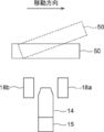
顕微鏡装置10は、観察対象である培養された細胞の位相差画像を撮像するものである。具体的には、顕微鏡装置10は、図1に示すように、白色光を出射する白色光源11、コンデンサレンズ12、スリット板13、結像光学系14、結像光学系駆動部15、撮像素子16および検出部18を備える。
The microscope device 10 captures a phase difference image of cultured cells to be observed. Specifically, as shown in FIG. 1, the microscope apparatus 10 includes a white light source 11 that emits white light, a condenser lens 12, a slit plate 13, an imaging optical system 14, an imaging optical system drive unit 15, and an imaging device. 16 and a detection unit 18.
スリット板13は、白色光源11から出射された白色光を遮光する遮光板に対して白色光を透過するリング形状のスリットが設けられたものであり、白色光がスリットを通過することによってリング状の照明光Lが形成される。
The slit plate 13 is provided with a ring-shaped slit for transmitting white light to a light shielding plate for shielding white light emitted from the white light source 11, and the white light passes through the slit to form a ring shape. Illumination light L is formed.
図2は、結像光学系14の詳細な構成を示す図である。結像光学系14は、図2に示すように、位相差レンズ14aおよび結像レンズ14dを備える。位相差レンズ14aは、対物レンズ14bおよび位相板14cを備える。位相板14cは、照明光Lの波長に対して透明な透明板に対して位相リングを形成したものである。なお、上述したスリット板13のスリットの大きさは、位相板14cの位相リングと共役な関係にある。
FIG. 2 is a diagram showing a detailed configuration of the imaging optical system 14. As shown in FIG. 2, the imaging optical system 14 includes a phase difference lens 14 a and an imaging lens 14 d. The phase difference lens 14a includes an objective lens 14b and a phase plate 14c. The phase plate 14 c has a phase ring formed on a transparent plate transparent to the wavelength of the illumination light L. The size of the slit of the slit plate 13 described above is in a conjugate relationship with the phase ring of the phase plate 14 c.
位相リングは、入射された光の位相を1/4波長ずらす位相膜と、入射された光を減光する減光フィルタとがリング状に形成されたものである。位相リングに入射された直接光は、位相リングを通過することによって位相が1/4波長ずれ、かつ明るさが弱められる。一方、観察対象によって回折された回折光は大部分が位相板14cの透明板を通過し、その位相および明るさは変化しない。
In the phase ring, a phase film for shifting the phase of the incident light by 1⁄4 wavelength and a light reducing filter for reducing the incident light are formed in a ring shape. The direct light incident on the phase ring is shifted in phase by 1⁄4 wavelength and is weakened in brightness by passing through the phase ring. On the other hand, most of the diffracted light diffracted by the object of observation passes through the transparent plate of the phase plate 14c, and its phase and brightness do not change.
対物レンズ14bを有する位相差レンズ14aは、図1に示す結像光学系駆動部15によって対物レンズ14bの光軸方向に移動する。なお、本実施形態においては、対物レンズ14bの光軸方向とZ方向(鉛直方向)とは同じ方向である。位相差レンズ14aのZ方向への移動によってオートフォーカス制御が行われ、撮像素子16によって撮像される位相差画像のコントラストが調整される。
The phase difference lens 14a having the objective lens 14b is moved in the optical axis direction of the objective lens 14b by the imaging optical system drive unit 15 shown in FIG. In the present embodiment, the optical axis direction of the objective lens 14b and the Z direction (vertical direction) are the same direction. The autofocus control is performed by the movement of the phase difference lens 14 a in the Z direction, and the contrast of the phase difference image captured by the imaging device 16 is adjusted.
また、位相差レンズ14aの倍率を変更可能な構成としてもよい。具体的には、異なる倍率を有する位相差レンズ14aまたは結像光学系14を交換可能に構成するようにしてもよい。位相差レンズ14aまたは結像光学系14の交換は、自動的に行うようにしてもよいし、ユーザが手動で行うようにしてもよい。
Further, the magnification of the phase difference lens 14a may be changed. Specifically, the phase difference lens 14a or the imaging optical system 14 having different magnifications may be configured to be exchangeable. The replacement of the phase difference lens 14a or the imaging optical system 14 may be performed automatically or may be performed manually by the user.
結像光学系駆動部15は、例えば圧電素子のようなアクチュエータを備え、後述するオートフォーカス制御部21から出力された制御信号に基づいて駆動する。なお、結像光学系駆動部15は、位相差レンズ14aを通過した位相差画像をそのまま通過させる構成となっている。また、結像光学系駆動部15の構成は圧電素子に限らず、位相差レンズ14aをZ方向に移動可能なものであればよく、その他の公知な構成を用いることができる。
The imaging optical system drive unit 15 includes an actuator such as a piezoelectric element, for example, and drives based on a control signal output from an autofocus control unit 21 described later. The imaging optical system drive unit 15 is configured to pass the phase difference image that has passed through the phase difference lens 14a as it is. Further, the configuration of the imaging optical system drive unit 15 is not limited to the piezoelectric element, as long as the retardation lens 14a can be moved in the Z direction, and other known configurations can be used.
結像レンズ14dは、位相差レンズ14aおよび結像光学系駆動部15を通過した位相差画像が入射され、これを撮像素子16に結像する。
The imaging lens 14 d receives the phase difference image that has passed through the phase difference lens 14 a and the imaging optical system drive unit 15, and forms an image on the imaging element 16.
撮像素子16は、結像レンズ14dによって結像された位相差画像を撮像する。撮像素子16としては、CCD(Charge-Coupled Device)イメージセンサまたはCMOS(Complementary Metal-Oxide Semiconductor)イメージセンサ等が用いられる。撮像素子としては、RGB(Red Green Blue)のカラーフィルタが設けられた撮像素子を用いてもよいし、モノクロの撮像素子を用いてもよい。
The imaging element 16 captures a phase difference image formed by the imaging lens 14d. As the imaging device 16, a charge-coupled device (CCD) image sensor, a complementary metal-oxide semiconductor (CMOS) image sensor, or the like is used. As an imaging device, an imaging device provided with a RGB (Red Green Blue) color filter may be used, or a monochrome imaging device may be used.
検出部18は、ステージ51に設置された培養容器50のZ方向(鉛直方向)の位置を検出する。検出部18は、具体的には、第1の変位センサ18aおよび第2の変位センサ18bを備える。第1の変位センサ18aおよび第2の変位センサ18bは、位相差レンズ14aを挟んで、図1に示すX方向に並べて設けられている。本実施形態における第1の変位センサ18aおよび第2の変位センサ18bはレーザ変位計であり、培養容器50にレーザ光を照射し、その反射光を検出することによって、培養容器50の底面のZ方向の位置を検出する。なお、培養容器50の底面とは、培養容器50の底部と観察対象である細胞との境界面、すなわち観察対象設置面である。
The detection unit 18 detects the position in the Z direction (vertical direction) of the culture container 50 installed on the stage 51. Specifically, the detection unit 18 includes a first displacement sensor 18a and a second displacement sensor 18b. The first displacement sensor 18a and the second displacement sensor 18b are provided side by side in the X direction shown in FIG. 1 with the phase difference lens 14a interposed therebetween. The first displacement sensor 18a and the second displacement sensor 18b in the present embodiment are laser displacement meters, and the culture vessel 50 is irradiated with laser light, and the reflected light is detected to detect Z on the bottom of the culture vessel 50. Detect the position of the direction. The bottom of the culture vessel 50 is the interface between the bottom of the culture vessel 50 and the cells to be observed, that is, the observation target installation surface.
検出部18によって検出された培養容器50のZ方向の位置を表す位置情報は、オートフォーカス制御部21に出力され、オートフォーカス制御部21は、入力された位置情報に基づいて、結像光学系駆動部15を制御し、オートフォーカス制御を行う。なお、第1の変位センサ18aおよび第2の変位センサ18bによる培養容器50の位置の検出およびオートフォーカス制御部21によるオートフォーカス制御については、後で詳述する。
Position information representing the position of the culture vessel 50 in the Z direction detected by the detection unit 18 is output to the autofocus control unit 21, and the autofocus control unit 21 generates an imaging optical system based on the input position information. The drive unit 15 is controlled to perform autofocus control. The detection of the position of the culture container 50 by the first displacement sensor 18a and the second displacement sensor 18b and the autofocus control by the autofocus control unit 21 will be described in detail later.
スリット板13と位相差レンズ14aおよび検出部18との間には、ステージ51が設けられている。ステージ51上には、観察対象である細胞が収容された培養容器50が設置される。
A stage 51 is provided between the slit plate 13 and the phase difference lens 14 a and the detection unit 18. On the stage 51, a culture container 50 containing cells to be observed is installed.
培養容器50としては、シャーレ、ディッシュまたはウェルプレート等を用いることができる。また、培養容器50に収容される細胞としては、iPS細胞およびES細胞といった多能性幹細胞、幹細胞から分化誘導された神経、皮膚、心筋および肝臓の細胞、並びに人体から取り出された皮膚、網膜、心筋、血球、神経および臓器の細胞等がある。
As the culture container 50, a petri dish, a dish, a well plate or the like can be used. Moreover, as cells accommodated in the culture vessel 50, pluripotent stem cells such as iPS cells and ES cells, nerves induced to differentiate from stem cells, cells of skin, myocardium and liver, skins removed from human body, retina, There are myocardium, blood cells, nerve and organ cells, etc.
ステージ51は、後述する水平方向駆動部17(図4参照)によって互いに直交するX方向およびY方向に移動する。X方向およびY方向は、Z方向に直交する方向であり、水平面内において互いに直交する方向である。本実施形態においては、X方向を主走査方向とし、Y方向を副走査方向とする。
The stage 51 is moved in the X direction and the Y direction orthogonal to each other by a horizontal direction drive unit 17 (see FIG. 4) described later. The X direction and the Y direction are directions orthogonal to the Z direction, and are directions orthogonal to each other in the horizontal plane. In the present embodiment, the X direction is the main scanning direction, and the Y direction is the sub scanning direction.
図3は、ステージ51の一例を示す図である。ステージ51の中央には、矩形の開口51aが形成されている。開口51aを形成する部材の上に培養容器50が設置され、培養容器50内の細胞の位相差画像が開口51aを通過するように構成されている。
FIG. 3 shows an example of the stage 51. As shown in FIG. At the center of the stage 51, a rectangular opening 51a is formed. The culture vessel 50 is placed on a member forming the opening 51a, and a phase difference image of cells in the culture vessel 50 is configured to pass through the opening 51a.
次に、顕微鏡装置10を制御する撮影制御装置20の構成について説明する。図4は、第1の実施形態の撮影制御装置の構成を示すブロック図である。なお、顕微鏡装置10については、撮影制御装置20の各部により制御される一部の構成のブロック図を示している。
Next, the configuration of the imaging control device 20 that controls the microscope apparatus 10 will be described. FIG. 4 is a block diagram showing the configuration of the imaging control apparatus of the first embodiment. In addition, about the microscope apparatus 10, the block diagram of the one part structure controlled by each part of the imaging | photography control apparatus 20 is shown.
撮影制御装置20は、顕微鏡装置10全体を制御するものであり、オートフォーカス制御部21、走査制御部22、処理制御部23および表示制御部24を備える。
The imaging control apparatus 20 controls the entire microscope apparatus 10, and includes an autofocus control unit 21, a scan control unit 22, a processing control unit 23, and a display control unit 24.
撮影制御装置20は、中央処理装置、半導体メモリおよびハードディスク等を備えたコンピュータから構成され、ハードディスクに本発明の観察装置制御プログラムの一実施形態がインストールされている。そして、この観察装置制御プログラムが中央処理装置によって実行されることによって、図4に示すオートフォーカス制御部21、走査制御部22、処理制御部23および表示制御部24が機能する。
The imaging control device 20 is configured of a computer provided with a central processing unit, a semiconductor memory, a hard disk and the like, and an embodiment of the observation device control program of the present invention is installed on the hard disk. Then, the central control unit executes this observation device control program, whereby the autofocus control unit 21, the scan control unit 22, the processing control unit 23, and the display control unit 24 shown in FIG. 4 function.
オートフォーカス制御部21は、上述したように検出部18によって検出された培養容器50のZ方向の位置情報に基づいて、結像光学系駆動部15を制御する。そして、結像光学系駆動部15の駆動によって結像光学系14の対物レンズ14bが光軸方向に移動し、オートフォーカス制御が行われる。
The autofocus control unit 21 controls the imaging optical system drive unit 15 based on the position information of the culture container 50 in the Z direction detected by the detection unit 18 as described above. Then, the objective lens 14 b of the imaging optical system 14 is moved in the optical axis direction by the drive of the imaging optical system drive unit 15, and autofocus control is performed.
走査制御部22は、水平方向駆動部17を駆動制御し、これによりステージ51をX方向およびY方向に移動させる。水平方向駆動部17は、圧電素子等を有するアクチュエータから構成される。
The scan control unit 22 drives and controls the horizontal drive unit 17 to move the stage 51 in the X direction and the Y direction. The horizontal drive unit 17 is configured of an actuator having a piezoelectric element or the like.
以下、走査制御部22によるステージ51の移動制御およびオートフォーカス制御部21によるオートフォーカス制御について、詳細に説明する。
Hereinafter, movement control of the stage 51 by the scan control unit 22 and autofocus control by the autofocus control unit 21 will be described in detail.
本実施形態においては、走査制御部22による制御によってステージ51をX方向およびY方向に移動させ、結像光学系14を培養容器50内において2次元状に走査し、結像光学系14による各観察位置の位相差画像を撮像する。図5は、培養容器50内における観察位置の走査位置を実線Mで示した図である。なお、本実施形態においては、培養容器50として6つのウェルWを有するウェルプレートを用いる。
In the present embodiment, the stage 51 is moved in the X direction and the Y direction under the control of the scan control unit 22, and the imaging optical system 14 is two-dimensionally scanned in the culture vessel 50. A phase difference image of the observation position is taken. FIG. 5 is a diagram showing the scanning position of the observation position in the culture container 50 by a solid line M. In the present embodiment, a well plate having six wells W is used as the culture vessel 50.
図5に示すように、結像光学系14は、走査開始点Sから走査終了点Eまで実線Mに沿って移動する。すなわち、結像光学系14による培養容器50上の観察位置は、X方向の正方向(図5の右方向)に走査された後、Y方向(図5の下方向)に移動し、逆の負方向(図5の左方向)に走査される。次いで、観察位置は、再びY方向に移動し、再び正方向に走査される。このように、結像光学系14は、X方向についての往復移動とY方向への移動を繰り返し行うことによって、培養容器50内を2次元状に走査する。
As shown in FIG. 5, the imaging optical system 14 moves along the solid line M from the scanning start point S to the scanning end point E. That is, the observation position on the culture vessel 50 by the imaging optical system 14 is moved in the Y direction (downward in FIG. 5) after being scanned in the positive direction (rightward in FIG. 5) in the X direction. It is scanned in the negative direction (left direction in FIG. 5). Then, the observation position is moved in the Y direction again and scanned in the positive direction again. As described above, the imaging optical system 14 two-dimensionally scans the inside of the culture container 50 by repeatedly performing reciprocating movement in the X direction and movement in the Y direction.
図6および図7は、培養容器50内の任意の位置に観察位置Rがある場合における結像光学系14、第1の変位センサ18aおよび第2の変位センサ18bと、培養容器50との位置関係を示した図である。
6 and 7 show the positions of the imaging optical system 14, the first displacement sensor 18a and the second displacement sensor 18b, and the culture container 50 when the observation position R is at an arbitrary position in the culture container 50. It is the figure which showed the relationship.
本実施形態においては、図6および図7に示すように、第1の変位センサ18aおよび第2の変位センサ18bが結像光学系14を挟んでX方向に並べて設けられている。そして、培養容器50は上述したように2次元状に走査されるが、この際、培養容器50におけるある観察位置Rが結像光学系14に到達する前に、移動方向(すなわち主走査方向)において結像光学系14に先行して、培養容器50の観察位置RにおけるZ方向の位置が検出される。具体的には、観察位置Rが図6に示す矢印方向(図6の左方向)に移動している場合には、第1の変位センサ18aおよび第2の変位センサ18bのうち、主走査方向において結像光学系14に先行する第1の変位センサ18aによって、培養容器50の観察位置RにおけるZ方向の位置が検出される。なお、図6においては、第1の変位センサ18aに斜線を付与している。そして、観察位置Rが、結像光学系14の位置まで移動した場合に、前もって検出された培養容器50のZ方向の位置情報が用いられてオートフォーカス制御が行われ、位相差画像の撮像が行われる。また、本実施形態においては、位相差画像の撮像後、主走査方向において結像光学系14に後続する第2の変位センサ18bによっても、培養容器50の観察位置RにおけるZ方向の位置が検出される。この場合、第1の変位センサ18aによる検出位置が第1の位置に、第2の変位センサ18bによる検出位置が第2の位置に対応する。
In the present embodiment, as shown in FIGS. 6 and 7, a first displacement sensor 18a and a second displacement sensor 18b are provided side by side in the X direction with the imaging optical system 14 interposed therebetween. Then, the culture vessel 50 is scanned in a two-dimensional manner as described above, in which case the moving direction (that is, the main scanning direction) is reached before a certain observation position R in the culture vessel 50 reaches the imaging optical system 14 The position in the Z direction at the observation position R of the culture vessel 50 is detected prior to the imaging optical system 14 in. Specifically, when the observation position R moves in the arrow direction (left direction in FIG. 6) shown in FIG. 6, the main scanning direction of the first displacement sensor 18a and the second displacement sensor 18b The position in the Z direction at the observation position R of the culture vessel 50 is detected by the first displacement sensor 18a preceding the imaging optical system 14 in. In FIG. 6, the first displacement sensor 18a is hatched. Then, when the observation position R moves to the position of the imaging optical system 14, the position information of the culture vessel 50 in the Z direction detected in advance is used to perform autofocus control, and imaging of the phase difference image is performed. To be done. Further, in the present embodiment, the position in the Z direction at the observation position R of the culture vessel 50 is also detected by the second displacement sensor 18b following the imaging optical system 14 in the main scanning direction after imaging the phase difference image. Be done. In this case, the detection position by the first displacement sensor 18a corresponds to the first position, and the detection position by the second displacement sensor 18b corresponds to the second position.
一方、観察位置Rが、図7の矢印方向(図7の右方向)に移動している場合には、第1の変位センサ18aおよび第2の変位センサ18bのうち、主走査方向において結像光学系14に先行する第2の変位センサ18bによって、培養容器50の観察位置RにおけるZ方向の位置が検出される。なお、図7においては、第2の変位センサ18bに斜線を付与している。そして、観察位置Rが図7に示す位置から結像光学系14の位置まで移動した場合に、前もって検出された培養容器50のZ方向の位置情報が用いられてオートフォーカス制御が行われ、位相差画像の撮像が行われる。また、本実施形態においては、位相差画像の撮像後、主走査方向において結像光学系14に後続する第1の変位センサ18aによっても培養容器50の観察位置RにおけるZ方向の位置が検出される。この場合、第2の変位センサ18bによる検出位置が第1の位置に、第1の変位センサ18aによる検出位置が第2の位置に対応する。
On the other hand, when the observation position R is moving in the direction of the arrow in FIG. 7 (the right direction in FIG. 7), an image is formed in the main scanning direction of the first displacement sensor 18a and the second displacement sensor 18b. The second displacement sensor 18b preceding the optical system 14 detects the position in the Z direction at the observation position R of the culture vessel 50. In FIG. 7, the second displacement sensor 18 b is hatched. Then, when the observation position R moves from the position shown in FIG. 7 to the position of the imaging optical system 14, the position information of the culture container 50 detected in advance in the Z direction is used to perform autofocus control. Imaging of the phase difference image is performed. Further, in the present embodiment, after the imaging of the phase difference image, the position in the Z direction at the observation position R of the culture container 50 is also detected by the first displacement sensor 18a following the imaging optical system 14 in the main scanning direction. Ru. In this case, the detection position by the second displacement sensor 18 b corresponds to the first position, and the detection position by the first displacement sensor 18 a corresponds to the second position.
なお、第1および第2の変位センサ18a,18bにより検出された培養容器50の方向の位置を表す位置情報は、各観察位置RのX-Y座標と対応づけられて、撮影制御装置20における不図示の半導体メモリまたはハードディスクに記憶される。
Position information representing the position of the culture container 50 in the direction detected by the first and second displacement sensors 18 a and 18 b is associated with the XY coordinates of each observation position R, and the imaging control device 20 It is stored in a semiconductor memory or a hard disk (not shown).
このように第1の変位センサ18aを用いた培養容器50のZ方向の位置の検出と第2の変位センサ18bを用いた培養容器50のZ方向の位置の検出とを、主走査方向の変更に応じて切り替えることによって、常に、観察位置Rの位相差画像の撮像に先行して、その観察位置Rの位置における培養容器50のZ方向の位置情報を取得することができる。
Thus, the detection of the position of the culture container 50 in the Z direction using the first displacement sensor 18a and the detection of the position of the culture container 50 in the Z direction using the second displacement sensor 18b are changes in the main scanning direction. By switching in accordance with the above, it is always possible to obtain positional information of the culture vessel 50 in the Z direction at the position of the observation position R prior to the imaging of the phase difference image at the observation position R.
そして、オートフォーカス制御部21は、上述したように結像光学系14に先行して検出された培養容器50のZ方向の位置情報に基づいて、結像光学系駆動部15を駆動制御することによって、オートフォーカス制御を行う。具体的には、オートフォーカス制御部21には、培養容器50のZ方向の位置情報と結像光学系14の光軸方向の移動量との関係が予め設定されている。オートフォーカス制御部21は、入力された培養容器50のZ方向の位置情報に基づいて、結像光学系14の光軸方向の移動量を求め、その移動量に応じた制御信号を結像光学系駆動部15に出力する。結像光学系駆動部15は、入力された制御信号に基づいて駆動し、これにより結像光学系14(対物レンズ14b)が光軸方向に移動し、培養容器50のZ方向の位置に応じたフォーカス調整が行われる。
The autofocus control unit 21 controls the drive of the imaging optical system drive unit 15 based on the position information of the culture vessel 50 in the Z direction detected prior to the imaging optical system 14 as described above. Perform auto focus control. Specifically, in the autofocus control unit 21, the relationship between the position information of the culture vessel 50 in the Z direction and the movement amount of the imaging optical system 14 in the optical axis direction is set in advance. The autofocus control unit 21 obtains the amount of movement of the imaging optical system 14 in the direction of the optical axis based on the input positional information of the culture vessel 50 in the Z direction, and generates a control signal corresponding to the amount of movement. It outputs to the system drive unit 15. The imaging optical system drive unit 15 is driven based on the input control signal, whereby the imaging optical system 14 (the objective lens 14b) is moved in the optical axis direction, and according to the position of the culture vessel 50 in the Z direction. Focus adjustment is performed.
本実施形態においては、上述したように各観察位置Rについてそれぞれ前もって培養容器50のZ方向の位置が検出されるため、各観察位置Rの培養容器50の位置の検出タイミングと、位相差画像の撮像タイミングが時間的にずれる。したがって、結像光学系14(対物レンズ14b)のZ方向の移動、すなわちオートフォーカス制御は、第1の変位センサ18aまたは第2の変位センサ18bによって培養容器50の位置の検出が行われた後、その検出位置に観察位置Rが到達するまでの間に行われる。
In the present embodiment, as described above, since the position of the culture vessel 50 in the Z direction is detected in advance for each observation position R, the detection timing of the position of the culture vessel 50 at each observation position R and the phase difference image The imaging timing is temporally shifted. Therefore, the movement of the imaging optical system 14 (the objective lens 14b) in the Z direction, that is, the autofocus control, is performed after the detection of the position of the culture vessel 50 by the first displacement sensor 18a or the second displacement sensor 18b. , Is performed until the observation position R reaches the detection position.
ここで、オートフォーカス制御のタイミングが早すぎる場合には、オートフォーカス制御の後、観察位置Rが検出位置に到達するまでの間に、何らかの要因によって、培養容器50のZ方向の位置がずれる可能性があり、フォーカス位置がずれる可能性がある。
Here, if the timing of the autofocus control is too early, after the autofocus control, the position of the culture vessel 50 in the Z direction may shift due to some factor until the observation position R reaches the detection position. And the focus position may shift.
したがって、オートフォーカス制御のタイミングは、観察位置Rが検出位置に到達する直前であって、かつその検出位置における位相差画像の撮像が間に合うタイミングであることが望ましい。なお、観察位置Rが検出位置に到達する直前とは、例えば図8に示すように、観察位置RがX方向に順次移動し、検出部18による検出位置が、斜線で示すPdの位置である場合には、観察位置Rが、検出位置Pdに隣接する観察位置Rの位置Prを通過した時点から検出位置Pdに到達するまでの間であることが望ましい。なお、観察位置Rが検出位置Pdに到達した時点でオートフォーカス制御を行うようにしてもよい。
Therefore, it is desirable that the timing of the autofocus control be immediately before the observation position R reaches the detection position, and at which the imaging of the phase difference image at the detection position is in time. Note that “immediately before the observation position R reaches the detection position” is, for example, as shown in FIG. 8, the observation position R sequentially moves in the X direction, and the detection position by the detection unit 18 is the position of Pd indicated by oblique lines. In this case, it is desirable that the observation position R be from the point of time when the position Pr of the observation position R adjacent to the detection position Pd passes to the point at which the detection position Pd is reached. The autofocus control may be performed when the observation position R reaches the detection position Pd.
本実施形態においては、オートフォーカス制御のタイミングが、上述したような望ましいタイミングとなるように、第1または第2の変位センサ18a,18bによる検出タイミングからその検出位置の位置情報を用いたオートフォーカス制御のタイミングまでの時間が予め設定されている。
In the present embodiment, the autofocus using the position information of the detection position from the detection timing by the first or second displacement sensor 18a, 18b so that the timing of the autofocus control becomes the desired timing as described above. The time until the timing of control is set in advance.
なお、例えば位相差レンズ14aの倍率の変更等によってステージ51の移動速度が変更された場合には、そのステージ51の移動速度の変更に応じて上記の予め設定された時間を変更してもよい。または、上記時間を変更する代わりに、ステージ51の移動速度が変更された場合に、第1の変位センサ18aまたは第2の変位センサ18bをX方向に移動させることによって、第1の変位センサ18aまたは第2の変位センサ18bと結像光学系14との距離を変更してもよい。
In addition, for example, when the moving speed of the stage 51 is changed by changing the magnification of the phase difference lens 14a or the like, the above-mentioned preset time may be changed according to the change of the moving speed of the stage 51. . Alternatively, instead of changing the above time, when the moving speed of the stage 51 is changed, the first displacement sensor 18a is moved by moving the first displacement sensor 18a or the second displacement sensor 18b in the X direction. Alternatively, the distance between the second displacement sensor 18 b and the imaging optical system 14 may be changed.
また、本実施形態のように、結像光学系14を挟んで第1の変位センサ18aおよび第2の変位センサ18bをX方向に並べて設け、位相差画像の撮像に先行して培養容器50の位置を検出する場合、培養容器50の範囲の全域において培養容器50の位置検出および位相差画像の撮像を行うには、図5に示すように、培養容器50の範囲よりもX方向について外側の範囲R1,R2まで結像光学系14、第1の変位センサ18aおよび第2の変位センサ18bを相対的に移動させる必要がある。そして、範囲R1のX方向の幅として、少なくとも第1の変位センサ18aと結像光学系14とのX方向の間隔を確保する必要があり、範囲R2のX方向の幅として、少なくとも第2の変位センサ18bと結像光学系14とのX方向の間隔を確保する必要がある。そして、観察位置Rの走査時間をできるだけ短縮するには、観察位置Rの走査範囲をできるだけ狭くすることが望ましい。したがって、範囲R1のX方向の幅は、第1の変位センサ18aと結像光学系14とのX方向の間隔とすることが望ましく、範囲R2のX方向の幅は、第2の変位センサ18bと結像光学系14とのX方向の間隔とすることが望ましい。
Further, as in the present embodiment, the first displacement sensor 18 a and the second displacement sensor 18 b are provided side by side in the X direction with the imaging optical system 14 interposed therebetween, and the culture container 50 is When detecting the position, in order to perform position detection of the culture container 50 and imaging of the phase difference image in the entire range of the culture container 50, as shown in FIG. It is necessary to move the imaging optical system 14, the first displacement sensor 18a, and the second displacement sensor 18b relatively to the ranges R1 and R2. Then, it is necessary to secure at least a distance between the first displacement sensor 18a and the imaging optical system 14 in the X direction as the width in the X direction of the range R1, and at least a second width in the X direction of the range R2. It is necessary to secure a distance between the displacement sensor 18 b and the imaging optical system 14 in the X direction. And in order to shorten the scanning time of observation position R as much as possible, it is desirable to make the scanning range of observation position R as narrow as possible. Therefore, the width in the X direction of the range R1 is preferably the distance between the first displacement sensor 18a and the imaging optical system 14 in the X direction, and the width in the X direction of the range R2 is the second displacement sensor 18b. It is desirable that the distance between the lens and the imaging optical system 14 be in the X direction.
一方、ステージ51をX方向に移動させることによって観察位置Rを培養容器50の範囲内において走査する場合、培養容器50の範囲における観察位置Rの移動速度は一定であることが望ましい。したがって、ステージ51のX方向への移動開始時にはステージ51が一定の速度になるまで加速する必要があり、ステージ51のX方向への移動終了時には、ステージ51を一定の速度から減速して停止させる必要がある。
On the other hand, when the observation position R is scanned within the range of the culture vessel 50 by moving the stage 51 in the X direction, it is desirable that the moving speed of the observation position R within the range of the culture vessel 50 be constant. Therefore, at the start of movement of the stage 51 in the X direction, it is necessary to accelerate the stage 51 to a constant speed, and at the end of movement of the stage 51 in the X direction, the stage 51 is decelerated from a constant speed and stopped. There is a need.
また、ステージ51のX方向への移動速度を一定の速度にする場合、加速域をほとんどもたせることなく急速に一定の速度に制御することは可能であるが、このような制御を行った場合、培養容器50に細胞と一緒に収容された培養液等の液面が揺れてしまい、位相差画像の画質の低下を招く可能性がある。また、ステージ51を停止する際にも同様の問題が発生する可能性がある。
In addition, when the moving speed of the stage 51 in the X direction is constant, it is possible to rapidly control the speed to a constant speed with almost no acceleration region, but when such control is performed, The liquid level of the culture solution or the like contained in the culture vessel 50 together with the cells may shake, which may lead to the deterioration of the image quality of the phase difference image. In addition, the same problem may occur when stopping the stage 51.
そこで、本実施形態においては、図5に示す範囲R1および範囲R2をステージ51のX方向への移動の加減速域に設定する。このように培養容器50の範囲のX方向の両側に加減速域を設定することによって、走査範囲を無駄に広げることなく、かつ培養容器50の範囲において観察位置Rを一定の速度で走査することができる。さらに、上述したような培養液の液面の揺れも抑制することができる。
Therefore, in the present embodiment, the range R1 and the range R2 shown in FIG. 5 are set in the acceleration / deceleration region of the movement of the stage 51 in the X direction. By setting the acceleration / deceleration zones on both sides in the X direction of the range of the culture vessel 50 in this way, the observation position R is scanned at a constant speed in the range of the culture vessel 50 without unnecessarily expanding the scanning range. Can. Furthermore, the fluctuation of the liquid level of the culture solution as described above can also be suppressed.
図4に戻り、処理制御部23は、処理対象となる対象観察位置R0について、第1の変位センサ18aが検出した培養容器50のZ方向の位置と、第2の変位センサ18bが検出した培養容器50のZ方向の位置との差分値の絶対値を算出する。そして、算出した差分値の絶対値が予め定められたしきい値Th1よりも大きいか否かを判定する。図9は培養容器50と第1および第2の変位センサ18a,18bとのZ方向の位置関係を示す図である。なお、図9においては、培養容器50は右方向に移動しているものとする。この場合、ある観察位置Rに関して、まずオートフォーカス制御のために第2の変位センサ18bにより培養容器50のZ方向の位置が検出され、その後、第1の変位センサ18aにより培養容器50のZ方向の位置が検出される。
Returning to FIG. 4, the processing control unit 23 controls the position in the Z direction of the culture container 50 detected by the first displacement sensor 18 a and the culture detected by the second displacement sensor 18 b at the target observation position R0 to be processed. The absolute value of the difference between the position of the container 50 and the Z direction is calculated. Then, it is determined whether the absolute value of the calculated difference value is larger than a predetermined threshold value Th1. FIG. 9 is a view showing the positional relationship between the culture container 50 and the first and second displacement sensors 18a and 18b in the Z direction. In addition, in FIG. 9, the culture container 50 is assumed to move to the right. In this case, with respect to a certain observation position R, first, the position of the culture vessel 50 in the Z direction is detected by the second displacement sensor 18b for autofocus control, and then the Z direction of the culture vessel 50 is detected by the first displacement sensor 18a. Position is detected.
ここで、第2の変位センサ18bによる検出時には図9に実線で示すように培養容器50が傾いていないが、振動が生じたり、水平方向駆動部17の精度等の影響により、第2の変位センサ18bによる検出後に、図9に破線で示すように、培養容器50が傾いてしまう場合がある。このような場合、第2の変位センサ18bが検出した培養容器50のZ方向の位置と、第1の変位センサ18aが検出した培養容器50のZ方向の位置とが異なるものとなる。このような状態においては、第1の変位センサ18aが検出した培養容器50のZ方向の位置と、第2の変位センサ18bが検出した培養容器50のZ方向の位置との差分値の絶対値は大きくなる。
Here, at the time of detection by the second displacement sensor 18b, although the culture container 50 is not inclined as shown by the solid line in FIG. 9, the second displacement is caused by vibration or the influence of the accuracy of the horizontal drive unit 17 or the like. After the detection by the sensor 18b, the culture vessel 50 may be tilted as shown by a broken line in FIG. In such a case, the position of the culture container 50 in the Z direction detected by the second displacement sensor 18b is different from the position of the culture container 50 in the Z direction detected by the first displacement sensor 18a. In such a state, an absolute value of a difference value between the position in the Z direction of the culture vessel 50 detected by the first displacement sensor 18a and the position in the Z direction of the culture vessel 50 detected by the second displacement sensor 18b. Will grow.
このように、算出した差分値の絶対値が大きい状態においては、走査時に結像光学系14に先行する変位センサにより検出された培養容器50のZ方向の位置に基づいて、観察位置Rのオートフォーカス制御を行っても、フォーカスが合っておらず、観察位置Rの画像はボケたものとなってしまう可能性がある。
As described above, in the state where the absolute value of the calculated difference value is large, the observation position R is automatically detected based on the position of the culture vessel 50 in the Z direction detected by the displacement sensor preceding the imaging optical system 14 at the time of scanning. Even when the focus control is performed, the image may not be in focus and the image at the observation position R may be blurred.
処理制御部23は、算出した差分値の絶対値がしきい値Th1よりも大きいと判定された場合、対象観察位置R0に対する観察のための処理を制御する。具体的には、対象観察位置の撮影および対象観察位置の画像に対する画像処理の少なくとも一方を制御する。以下、撮影および画像処理の制御について説明する。
When it is determined that the calculated absolute value of the difference value is larger than the threshold value Th1, the processing control unit 23 controls processing for observation at the target observation position R0. Specifically, at least one of imaging of a target observation position and image processing on an image of the target observation position is controlled. Hereinafter, control of photographing and image processing will be described.
まず、撮影の制御について説明する。処理制御部23は、差分値の絶対値がしきい値Th1よりも大きいと判定された対象観察位置R0を再撮影する。ここで、差分値の絶対値がしきい値Th1よりも大きいということは、対象観察位置R0にフォーカスが合わせられていない可能性が高く、対象観察位置R0の位相差画像がボケている可能性が高いこと意味する。このため、処理制御部23は、顕微鏡装置10に対して、対象観察位置R0に対してフォーカスが適切に合わせられるように指示を行って、対象観察位置R0の再撮影を行う。ここで、培養容器50のZ方向の位置情報は、上述したように観察位置RのX-Y座標と対応づけられて記憶されている。このため、対象観察位置R0の位置は容易に特定することができる。
First, control of imaging will be described. The processing control unit 23 rephotographs the target observation position R0 determined to have the absolute value of the difference value larger than the threshold value Th1. Here, if the absolute value of the difference value is larger than the threshold value Th1, there is a high possibility that the target observation position R0 is not focused, and the phase difference image at the target observation position R0 may be blurred. Means higher. For this reason, the process control unit 23 instructs the microscope device 10 to appropriately focus on the target observation position R0, and rephotographs the target observation position R0. Here, the position information of the culture vessel 50 in the Z direction is stored in association with the XY coordinates of the observation position R as described above. Therefore, the position of the target observation position R0 can be easily identified.
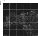
なお、処理制御部23は、算出した差分値の絶対値がしきい値Th1よりも大きいと判定された場合、対象観察位置R0がボケている可能性が高いことを通知するようにしてもよい。具体的には、本実施形態においては、後述するように表示制御部24が、複数の位相差画像を繋げて合成した合成画像を表示装置30に表示するが、表示装置30に表示された合成画像において、算出した差分値の絶対値がしきい値Th1よりも大きくなった観察領域の位相差画像を強調して表示することにより通知を行えばよい。例えば、図10に示す合成画像において、点線で囲まれた観察領域Rについて、算出した差分値の絶対値がしきい値Th1よりも大きくなったとする。この場合、点線で囲まれた領域に赤色等の枠を付与したり、枠を点滅させたり、領域を点滅させる等により、その領域の位相差画像を強調して表示すればよい。また、テキストまたは音声により通知をしてもよい。
Note that the process control unit 23 may notify that the target observation position R0 is highly likely to be blurred when it is determined that the calculated absolute value of the difference value is larger than the threshold value Th1. . Specifically, in the present embodiment, as described later, the display control unit 24 displays on the display device 30 a composite image obtained by connecting and combining a plurality of phase difference images, but the composite displayed on the display device 30 In the image, the notification may be performed by emphasizing and displaying the phase difference image of the observation area in which the absolute value of the calculated difference value is larger than the threshold value Th1. For example, in the synthesized image shown in FIG. 10, it is assumed that the absolute value of the calculated difference value is larger than the threshold value Th1 for the observation region R surrounded by the dotted line. In this case, the phase difference image of the area may be emphasized and displayed by providing a frame such as red in the area surrounded by the dotted line, blinking the frame, or blinking the area. Also, notification may be made by text or voice.
次に画像処理の制御について説明する。処理制御部23は、算出した差分値の絶対値がしきい値Th1よりも大きいと判定された場合、対象観察位置R0の位相差画像に対して、シャープネス強調処理を行う。具体的には、算出した差分値の絶対値の大きさに応じてシャープネスの強調度を変更してシャープネス強調処理を行う。なお、本実施形態においては、各種差分値の値とシャープネスの強調度とを対応づけたテーブルが撮影制御装置20のハードディスクに記憶されている。処理制御部23は、このテーブルを参照して差分値の値に応じたシャープネスの強調度を取得して、対象観察位置R0の位相差画像に対してシャープネス強調処理を行う。
Next, control of image processing will be described. When it is determined that the absolute value of the calculated difference value is larger than the threshold value Th1, the processing control unit 23 performs sharpness enhancement processing on the phase difference image at the target observation position R0. Specifically, the degree of emphasis of sharpness is changed according to the magnitude of the absolute value of the calculated difference value to perform the sharpness emphasis process. In the present embodiment, a table in which the values of various difference values are associated with the degree of emphasis of sharpness is stored in the hard disk of the imaging control apparatus 20. The process control unit 23 refers to this table to acquire the degree of sharpness enhancement according to the value of the difference value, and performs the sharpness enhancement process on the phase difference image at the target observation position R0.
次に、図4に戻り、表示制御部24は、顕微鏡装置10によって撮像された各観察位置Rの位相差画像を結合することによって、1枚の合成位相差画像を生成し、その合成位相差画像を表示装置30に表示させる。なお、観察位置が再撮影された場合は、再撮影により取得された位相差画像を用いて合成位相差画像を生成する。また、観察位置の位相差画像に対してシャープネス強調処理が行われた場合は処理済みの位相差画像を用いて合成位相差画像を生成する。
Next, returning to FIG. 4, the display control unit 24 combines the phase difference images of the respective observation positions R captured by the microscope device 10 to generate one combined phase difference image, and the combined phase difference thereof. An image is displayed on the display device 30. In addition, when an observation position is rephotographed, a synthetic | combination phase difference image is produced | generated using the phase difference image acquired by rephotographing. When sharpness enhancement processing is performed on the phase difference image at the observation position, a synthesized phase difference image is generated using the processed phase difference image.
表示装置30は、上述したように表示制御部24によって生成された合成位相差画像を表示するものであり、例えば液晶ディスプレイ等を備える。また、表示装置30をタッチパネルによって構成し、入力装置40と兼用してもよい。
The display device 30 displays the composite phase difference image generated by the display control unit 24 as described above, and includes, for example, a liquid crystal display or the like. In addition, the display device 30 may be configured by a touch panel and used as the input device 40.
入力装置40は、マウスおよびキーボード等を備えたものであり、ユーザによる種々の設定入力を受け付ける。本実施形態の入力装置40は、例えば位相差レンズ14aの倍率の変更指示およびステージの移動速度の変更指示等の設定入力を受け付ける。
The input device 40 includes a mouse, a keyboard, and the like, and receives various setting inputs from the user. The input device 40 according to the present embodiment receives setting inputs such as, for example, an instruction to change the magnification of the phase difference lens 14 a and an instruction to change the moving speed of the stage.
次に、本実施形態の顕微鏡観察システムが行う処理について説明する。図11および図12は第1の実施形態において行われる処理を示すフローチャートである。まず、観察対象である細胞が収容された培養容器50が、ステージ51上に設置される(ステップST10)。次に、ステージ51が移動して結像光学系14が、図5に示す走査開始点Sの位置に設定され、培養容器50の走査が開始される(ステップST12)。
Next, processing performed by the microscope observation system of the present embodiment will be described. 11 and 12 are flowcharts showing the processing performed in the first embodiment. First, the culture vessel 50 containing cells to be observed is placed on the stage 51 (step ST10). Next, the stage 51 is moved, the imaging optical system 14 is set at the position of the scanning start point S shown in FIG. 5, and the scanning of the culture vessel 50 is started (step ST12).
ここで、本実施形態においては、上述したように各観察位置Rについて、撮像に先行して培養容器50のZ方向の位置検出が行われ、その検出位置まで観察位置Rが到達した時点において、位相差画像の撮像が行われる。そして、この培養容器50の位置検出と位相差画像の撮像は、培養容器50を走査しながら行われ、ある観察位置Rの位相差画像の撮像と、観察位置Rの撮像前における観察位置Rに対応する培養容器50のZ方向の位置検出とが並行して行われる。
Here, in the present embodiment, as described above, position detection of the culture container 50 in the Z direction is performed prior to imaging at each observation position R, and when the observation position R reaches the detection position, Imaging of the phase difference image is performed. The position detection of the culture vessel 50 and the imaging of the phase difference image are performed while scanning the culture vessel 50, and the imaging of the phase difference image at a certain observation position R and the observation position R before the observation position R are performed. The position detection of the corresponding culture vessel 50 in the Z direction is performed in parallel.
具体的には、図6の矢印方向に培養容器50が移動している場合には、第1の変位センサ18aによって培養容器50のZ方向の位置が検出され(ステップST14)、その検出された位置情報が、オートフォーカス制御部21によって取得される。オートフォーカス制御部21は、取得した培養容器50のZ方向の位置情報に基づいて、対物レンズ14bの移動量を算出し(ステップST16)、対物レンズ14bの移動量を培養容器50の検出位置のX-Y座標上の位置と対応づけて記憶する(ステップST18)。なお、この際、第1の変位センサ18aおよび第2の変位センサ18bによって検出された、培養容器50のZ方向の位置も、培養容器50の検出位置のX-Y座標上の位置と対応づけて記憶される。
Specifically, when the culture container 50 is moving in the arrow direction of FIG. 6, the position of the culture container 50 in the Z direction is detected by the first displacement sensor 18a (step ST14), and the detection is performed Position information is acquired by the autofocus control unit 21. The autofocus control unit 21 calculates the amount of movement of the objective lens 14b based on the acquired position information of the culture container 50 in the Z direction (step ST16), and the amount of movement of the objective lens 14b corresponds to the detection position of the culture container 50. It is stored in association with the position on the XY coordinates (step ST18). At this time, the position in the Z direction of the culture vessel 50 detected by the first displacement sensor 18a and the second displacement sensor 18b is also correlated with the position on the XY coordinates of the detection position of the culture vessel 50. Are stored.
次いで、ステップST14において第1の変位センサ18aによって培養容器50の位置検出が行われた位置に向かって観察位置Rが移動する(ステップST20)。そして、オートフォーカス制御部21は、培養容器50の位置検出が行われた位置に観察位置Rが到達する直前において記憶された対物レンズ14bの移動量を取得し、取得した移動量に基づいてオートフォーカス制御を行う(ステップST22,ST24)。すなわち、オートフォーカス制御部21は、予め記憶された移動量に基づいて結像光学系駆動部15を駆動制御し、対物レンズ14bをZ方向に移動させる。そして、オートフォーカス制御後、培養容器50の位置検出が行われた位置に観察位置Rが到達した時点において、位相差画像の撮像を行う(ステップST26)。観察位置Rの位相差画像は、撮像素子16から表示制御部24に出力されて記憶される。なお、上述したように、ステップST26における観察位置Rの位相差画像の撮像が行われている間、各観察位置Rよりも走査方向において先行する変位センサによる培養容器50の位置検出が並行して行われる。
Next, at step ST14, the observation position R moves toward the position at which the position detection of the culture container 50 has been performed by the first displacement sensor 18a (step ST20). Then, the autofocus control unit 21 acquires the movement amount of the objective lens 14b stored immediately before the observation position R reaches the position where the position detection of the culture vessel 50 is performed, and performs the auto based on the acquired movement amount. Focus control is performed (steps ST22 and ST24). That is, the autofocus control unit 21 controls the drive of the imaging optical system drive unit 15 based on the movement amount stored in advance, and moves the objective lens 14b in the Z direction. Then, after the autofocus control, when the observation position R reaches the position at which the position detection of the culture container 50 is performed, imaging of the phase difference image is performed (step ST26). The phase difference image at the observation position R is output from the imaging element 16 to the display control unit 24 and stored. As described above, while the imaging of the phase difference image at the observation position R in step ST26 is performed, the position detection of the culture container 50 by the displacement sensor preceding in the scanning direction with respect to each observation position R is performed in parallel. To be done.
次いで、ステップST28において、第2の変位センサ18bの位置に対象観察位置R0が移動し、第2の変位センサ18bによって対象観察位置R0における培養容器50のZ方向の位置が検出され、培養容器50の検出位置のX-Y座標上の位置と対応づけて記憶される。
Next, in step ST28, the target observation position R0 is moved to the position of the second displacement sensor 18b, and the second displacement sensor 18b detects the position of the culture container 50 in the Z direction at the target observation position R0. Are stored in association with the position on the XY coordinates of the detected position of.
そして、結像光学系14による観察位置Rが、図5に示す加減速域の範囲R2まで移動し、Y方向に移動した後、X方向について逆方向に走査される場合には(ステップST30,YES)、すなわち、主走査方向が、図6の矢印方向から図7の矢印方向に変更された場合には、オートフォーカス制御に使用する変位センサを第1の変位センサ18aから第2の変位センサ18bに切り替える(ステップST32)。ステップST30が否定された場合には、上述した培養容器50の位置検出と位相差画像の撮像が順次行われる(ステップST14~ステップST28)。
Then, after the observation position R by the imaging optical system 14 moves to the range R2 of the acceleration / deceleration area shown in FIG. 5 and moves in the Y direction, it is scanned in the reverse direction in the X direction (step ST30, YES), that is, when the main scanning direction is changed from the direction of the arrow in FIG. 6 to the direction of the arrow in FIG. 7, the displacement sensor used for the autofocus control from the first displacement sensor 18a to the second displacement sensor It switches to 18b (step ST32). When the step ST30 is denied, the above-mentioned position detection of the culture container 50 and the imaging of the phase difference image are sequentially performed (step ST14 to step ST28).
そして、全ての走査が終了していない場合には(ステップST34,NO)、再び、観察位置RがX方向に移動し、上述した培養容器50の位置検出と位相差画像の撮像が順次行われる(ステップST14~ステップST28)。
Then, if all the scans have not been completed (NO in step ST34), the observation position R moves in the X direction again, and the above-described position detection of the culture container 50 and the imaging of the phase difference image are sequentially performed. (Steps ST14 to ST28).
観察位置Rが、加減速域の範囲R1,R2まで移動する度に使用する変位センサが切り替えられ、全ての走査が終了するまでステップST14~ステップST28までの処理が繰り返して行われる。そして、観察位置Rが、図5に示す走査終了点Eの位置に到達した時点において全ての走査が終了する(ステップST34,YES)。
The displacement sensor to be used is switched each time the observation position R moves to the range R1, R2 of the acceleration / deceleration region, and the processing from step ST14 to step ST28 is repeated until all scanning is completed. Then, when the observation position R reaches the position of the scanning end point E shown in FIG. 5, all the scanning ends (step ST34, YES).
全ての走査が終了した後、処理制御部23は、複数の観察位置のうちの対象観察位置R0について、第1の変位センサ18aが検出した培養容器50のZ方向の位置と、第2の変位センサ18bが検出した培養容器50のZ方向の位置との差分値の絶対値を算出する。(ステップST36)。そして、算出した差分値の絶対値がしきい値Th1よりも大きいか否かを判定する(ステップST38)。
After all the scans are completed, the processing control unit 23 determines the position of the culture vessel 50 in the Z direction detected by the first displacement sensor 18a and the second displacement for the target observation position R0 among the plurality of observation positions. The absolute value of the difference value with the position of the culture vessel 50 in the Z direction detected by the sensor 18 b is calculated. (Step ST36). Then, it is determined whether the absolute value of the calculated difference value is larger than the threshold value Th1 (step ST38).
ステップST38が肯定されると、処理制御部23は、対象観察位置R0に対する観察のための処理を制御する(ステップST40)。具体的には、対象観察位置R0の再撮影、対象観察位置R0の位相差画像がボケている可能性が高いことの通知、または対象観察位置R0の位相差画像に対するシャープネス強調処理を行う。なお、ステップST38が否定された場合、ステップST42の処理に進む。
If step ST38 is affirmed, the process control unit 23 controls the process for observing the target observation position R0 (step ST40). Specifically, re-imaging at the target observation position R0, notification that the phase difference image at the target observation position R0 is likely to be blurred, or sharpness enhancement processing on the phase difference image at the target observation position R0 is performed. If step ST38 is negative, the process proceeds to step ST42.
そして、全ての観察位置Rの判定が終了するまでステップST36~ST40の処理が繰り返される(ST42,NO)。全ての観察位置Rの判定が終了した場合には(ST42,YES)、表示制御部24は全ての位相差画像を繋ぎ合わせて合成して合成位相差画像を生成し、生成した合成位相差画像を表示装置30に表示し(ステップST44)、処理を終了する。
Then, the processing of steps ST36 to ST40 is repeated until the determination of all the observation positions R is completed (ST42, NO). When the determination of all the observation positions R is completed (ST 42, YES), the display control unit 24 combines all the phase difference images and combines them to generate a combined phase difference image, and generates the combined phase difference image Are displayed on the display device 30 (step ST44), and the process is ended.
このように、本実施形態においては、結像光学系14が培養容器50内の対象観察位置に到達する前に、主走査方向において対象観察位置R0に先行する変位センサによって検出された、対象観察位置R0における培養容器50の鉛直方向の第1の位置に基づいて、オートフォーカス制御を行うようにした。このため、高速にオートフォーカス制御を行うことができる。
Thus, in the present embodiment, the target observation detected by the displacement sensor preceding the target observation position R0 in the main scanning direction before the imaging optical system 14 reaches the target observation position in the culture vessel 50 The autofocus control is performed based on the first position in the vertical direction of the culture container 50 at the position R0. Therefore, autofocus control can be performed at high speed.
また、第1および第2の変位センサ18a,18bによって検出された対象観察位置R0における培養容器50の鉛直方向の位置に基づいて、対象観察位置R0に対する観察のための処理を制御するようにした。このため、主走査方向に先行する変位センサによる検出後に、振動等により培養容器50の鉛直方向の位置が変化しても、主走査方向に後続する変位センサにより、その変化を検出することができる。したがって、観察のための制御がなされた、対象観察位置R0における位相差画像を用いることができ、これにより、観察対象に対して正確かつ信頼性の高い評価を行うことができる。
Also, based on the position in the vertical direction of the culture vessel 50 at the target observation position R0 detected by the first and second displacement sensors 18a and 18b, the processing for observation at the target observation position R0 is controlled. . Therefore, even if the vertical position of the culture vessel 50 changes due to vibration or the like after detection by the displacement sensor preceding in the main scanning direction, the change can be detected by the displacement sensor following in the main scanning direction. . Therefore, it is possible to use a phase difference image at the target observation position R0 which is controlled for observation, and thereby, it is possible to perform accurate and highly reliable evaluation on the observation target.
次いで、本発明の第2の実施形態について説明する。なお、本発明の撮影制御装置、方法およびプログラムの第2の実施形態を用いた顕微鏡観察システムの構成は、図1に示す第1の実施形態を用いた顕微鏡観察システムの構成と同一であり、処理制御部23が行う処理のみが異なる。このため、構成についての説明は省略する。
Next, a second embodiment of the present invention will be described. The configuration of a microscope observation system using the second embodiment of the imaging control apparatus, method and program of the present invention is the same as the configuration of the microscope observation system using the first embodiment shown in FIG. Only the processing performed by the processing control unit 23 is different. Therefore, the description of the configuration is omitted.
上記第1の実施形態においては、算出した差分値の絶対値がしきい値Th1よりも大きいと判定された場合、対象観察位置R0に対する観察のための処理を制御している。具体的には、対象観察位置の撮影および対象観察位置の画像に対する画像処理の少なくとも一方を制御している。第2の実施形態においては、処理制御部23は、さらに対象観察位置R0の位相差画像に含まれる細胞の状態を評価するようにし、算出した差分値の絶対値がしきい値Th1よりも大きいか否かに応じて、位相差画像の評価方法を変更するようにした点が第1の実施形態と異なる。以下、画像の評価について説明する。
In the first embodiment, when it is determined that the absolute value of the calculated difference value is larger than the threshold value Th1, the processing for observation at the target observation position R0 is controlled. Specifically, at least one of imaging of a target observation position and image processing on an image of the target observation position is controlled. In the second embodiment, the processing control unit 23 further evaluates the state of the cells included in the phase difference image at the target observation position R0, and the calculated absolute value of the difference value is larger than the threshold value Th1. This embodiment differs from the first embodiment in that the evaluation method of the phase difference image is changed depending on whether or not it is. Hereinafter, evaluation of the image will be described.
第2の実施形態においては、処理制御部23は、観察位置R毎の位相差画像に含まれる細胞の状態を評価することにより、対象観察位置R0に対する観察のための処理を制御する。細胞の状態を評価するとは、例えば位相差画像に含まれる細胞が未分化細胞であるのか分化細胞であるのかを評価したり、共培養の際の細胞の種類ごとの細胞数をカウントしたり、位相差画像に含まれる未分化細胞と分化細胞の割合を評価したり、細胞または細胞コロニーの成長度を評価したり、または抗がん剤によるがん細胞の縮小率を評価したりすることをいう。ただし、細胞の状態の評価としては、これらに限らず、その他の評価でもよい。
In the second embodiment, the process control unit 23 controls the process for observation at the target observation position R0 by evaluating the state of the cells included in the phase difference image for each observation position R. Assessing the state of cells means, for example, evaluating whether the cells included in the phase contrast image are undifferentiated cells or differentiated cells, counting the number of cells for each cell type during co-culture, Evaluating the proportion of undifferentiated cells and differentiated cells contained in the phase contrast image, evaluating the degree of growth of cells or cell colonies, or evaluating the reduction rate of cancer cells by anticancer drugs Say. However, as evaluation of the state of a cell, not only these but other evaluation may be sufficient.
ここで、算出した差分値がしきい値Th1より大きい場合、位相差画像はボケているか、またはボケている可能性が高く、差分値がしきい値以下の場合は位相差画像はボケていないか、またはボケていない可能性が高い。第2の実施形態における処理制御部23は、ボケている位相差画像(差分値の絶対値>Th1、以下ボケている可能性が高い位相差画像を含む)と、ボケていない位相差画像(差分値の絶対値≦Th1。以下ボケていない可能性が高い位相差画像を含む)とで異なる評価方法で細胞の状態を評価する。具体的には、処理制御部23は、ボケていない位相差画像については、その位相差画像に含まれる細胞の状態を示す特徴量を用いて評価し、ボケている位相差画像については、画像特徴量を用いて評価する。
Here, when the calculated difference value is larger than the threshold value Th1, the phase difference image is likely to be blurred or blurred, and when the difference value is less than or equal to the threshold value, the phase difference image is not blurred. There is a high possibility that it is not blurred or not. The processing control unit 23 in the second embodiment includes a blurred phase difference image (absolute value of difference value> Th1, including a phase difference image having a high possibility of being blurred below) and an unblurred phase difference image ( Evaluate the state of cells by different evaluation methods with the absolute value of the difference value ≦ Th1 (including the phase difference image with high possibility of blurring below). Specifically, the processing control unit 23 evaluates the phase difference image that is not blurred using the feature amount that indicates the state of the cells included in the phase difference image, and for the phase difference image that is blurred, the image Evaluate using feature quantities.
ボケていない位相差画像については、位相差画像に含まれる細胞の画像または核もしくは核小体等の細胞の微細構造の画像を高精度に認識することができる。このため、上述したように細胞の状態を示す特徴量を用いて評価することによって、生物学的な説明力に優れる評価結果を得ることができる。逆に言えば、細胞の状態を示す特徴量を用いた評価方法は、相対的にボケ(劣化)に弱い評価方法といえる。
With regard to a phase difference image that is not blurred, an image of a cell included in the phase difference image or an image of a fine structure of a cell such as a nucleus or a nucleolus can be recognized with high accuracy. For this reason, it is possible to obtain an evaluation result excellent in biological explanatory power by performing evaluation using the feature amount indicating the state of the cell as described above. Conversely speaking, it can be said that the evaluation method using the feature quantity indicating the state of the cell is a weak evaluation method against blurring (deterioration) relatively.
細胞の状態を示す特徴量としては、個々の細胞の状態の特徴量、細胞内に含まれる核小体の特徴量、白すじの特徴量、細胞内に含まれる核の特徴量および細胞のNC比の少なくとも1つを用いることができる。
The feature quantities that indicate the state of the cell include the feature quantity of the individual cell state, the feature quantity of the nucleolus contained in the cell, the feature quantity of the white streaks, the feature quantity of the nucleus contained in the cell and the NC of the cell At least one of the ratios can be used.
個々の細胞の状態の特徴量としては、例えば細胞の数、細胞の密度、細胞の増加率および細胞の円形度等があるが、位相差画像に含まれる個々の細胞を認識し、その認識した細胞に基づいて算出される特徴量であればその他の特徴量でもよい。位相差画像に含まれる細胞の認識方法としては、例えば細胞の画像のエッジを検出したり、パターンマッチング処理を用いて検出したり、機械学習によって生成された判別器を用いて検出したりする方法があるが、その他の公知な手法を用いることができる。なお、細胞の円形度については、未分化細胞は円形度が相対的に高くなるが、分化細胞は、例えば細長い形状となり、円形度が相対的に低くなる。したがって、個々の細胞の円形度を算出することによって分化細胞であるか、または未分化細胞であるかを評価することができる。また、多能性幹細胞において、細胞が分化すると核内のクロマチン構造が変化し黒っぽくなるため、核を検出した後に核の輝度を評価することによって分化または未分化を評価することができる。但し、分化細胞か未分化細胞かを評価する方法としては、これに限らず、その他の公知な手法を用いることができる。または、神経細胞を評価する場合には、個々の細胞の状態を示す特徴量として、樹状突起の長さを用いることができる。樹状突起の長さを用いることによって、神経細胞の成長度を評価することができる。
The characteristic quantities of individual cell states include, for example, the number of cells, the density of cells, the growth rate of cells, and the degree of circularity of cells, but the individual cells included in the phase contrast image were recognized and recognized Other feature quantities may be used as long as they are feature quantities calculated based on cells. As a method of recognizing cells included in the phase difference image, for example, a method of detecting an edge of an image of a cell, detecting using a pattern matching process, or detecting using a discriminator generated by machine learning However, other known techniques can be used. With regard to the degree of circularity of cells, undifferentiated cells have relatively high degree of circularity, but differentiated cells have, for example, an elongated shape and relatively low degree of circularity. Therefore, it can be evaluated whether it is a differentiated cell or an undifferentiated cell by calculating the degree of circularity of each cell. In pluripotent stem cells, when the cells differentiate, the chromatin structure in the nucleus changes and becomes dark. Therefore, differentiation or undifferentiation can be evaluated by evaluating the brightness of the nucleus after detecting the nucleus. However, the method for evaluating whether a differentiated cell or an undifferentiated cell is not limited to this, and other known methods can be used. Alternatively, when evaluating nerve cells, dendrite length can be used as a feature that indicates the state of individual cells. By using the dendrite length, it is possible to assess the degree of neural cell growth.
また、細胞内に含まれる核または核小体の特徴量としては、例えば核または核小体の数、核または核小体の密度および核または核小体の増加率等があるが、位相差画像に含まれる核または核小体を認識し、その認識した核または核小体に基づいて算出される特徴量であればその他の特徴量でもよい。位相差画像に含まれる核または核小体の認識方法としては、細胞の認識方法と同様に、エッジ検出、パターンマッチングによる検出および判別器を用いた検出等を用いることができる。
In addition, the characteristic quantities of nuclei or nuclear bodies contained in cells include, for example, the number of nuclei or nuclear bodies, the density of nuclei or nuclear bodies, and the increase rate of nuclei or nuclear bodies, etc. As long as it is a feature that recognizes nuclei or nucleolus contained in an image and is calculated based on the recognized nuclei or nucleolus, other features may be used. As a method of recognizing nuclei or nuclear bodies contained in the phase difference image, edge detection, detection by pattern matching, detection using a discriminator, and the like can be used as in the method of cell recognition.
また、白すじとは、細胞と背景間に発生する回折光による光のにじみ(ハロ)のことである。そして、白すじの特徴量としては、例えば白すじの総面積、白すじの密度および白すじの分布状態等があるが、位相差画像に含まれる白すじを認識し、その認識した白すじに基づいて算出される特徴量であればその他の特徴量でもよい。白すじの認識方法としては、例えば位相差画像を2値化し、しきい値処理によって白すじを抽出するようにしてもよいし、パターンマッチング処理を用いて検出したり、機械学習によって生成された判別器を用いて検出したりする方法があるが、その他の公知な手法を用いることができる。なお、白すじの特徴量については、例えば細胞コロニー内に未分化細胞が多い状態では白すじは少ないが、分化が進み分化細胞が多くなると白すじの量が多くなる。したがって、白すじの特徴量に基づいて、細胞コロニーの分化度または未分化度、もしくは細胞コロニーの成長度等を評価することができる。
In addition, white streaks are light blur (halo) due to diffracted light generated between cells and background. Then, the feature quantities of white streaks include, for example, the total area of white streaks, the density of white streaks, and the distribution state of white streaks, and the white streaks recognized in the phase difference image are recognized and recognized. Other feature quantities may be used as long as they are feature quantities calculated based on the above. As a method of recognizing white streaks, for example, a phase difference image may be binarized and white streaks may be extracted by threshold processing, detected by using pattern matching processing, or generated by machine learning. Although there is a method of detecting using a discriminator, other known methods can be used. With regard to the feature amount of white streaks, for example, while white streaks are small when there are many undifferentiated cells in cell colonies, differentiation progresses and the number of white streaks increases as the number of differentiated cells increases. Therefore, the differentiation degree or the undifferentiated degree of the cell colony, the growth degree of the cell colony, etc. can be evaluated based on the characteristic amount of the white streak.
また、細胞のNC比とは、核/細胞質面積比である。NC比については、細胞質と核のそれぞれの検出器を使用することで求めることができる。細胞質は、一般的にグレーかつフラットな見た目を有し、これに対し、核は比較的丸くかつ内部に核小体等の構造を含む。したがって、それぞれの検出器を機械学習により作成し、位相差画像に適用することによって細胞質領域と核領域とが得られる。このようにして得られた細胞質領域と核領域との面積の比を算出することによって、NC比を算出することができる。NC比は、細胞コロニー単位で算出してもよいし、予め指定された領域内でのNC比を算出するようにしてもよい。
Also, the NC ratio of cells is the nuclear / cytoplasmic area ratio. The NC ratio can be determined by using the cytoplasmic and nuclear detectors. The cytoplasm generally has a gray and flat appearance, whereas the nuclei are relatively round and contain structures such as nucleoli internally. Therefore, a cytoplasmic region and a nuclear region are obtained by creating each detector by machine learning and applying it to the phase difference image. The NC ratio can be calculated by calculating the ratio of the area of the cytoplasmic region to the nuclear region obtained in this manner. The NC ratio may be calculated in cell colony units, or may be calculated in a previously designated region.
一方、ボケた位相差画像については、個々の細胞の画像または核小体の画像等の検出精度が低くなる。したがって、ボケていない位相差画像のように個々の細胞の状態を示す特徴量を用いて評価するよりも、位相差画像自体の画像特徴量を用いて評価した方が、評価精度が向上する。画像特徴量を用いた評価方法は、上述した細胞の状態を示す特徴量を用いた評価方法よりも、相対的にボケ(劣化)に強い評価方法といえる。
On the other hand, in the case of a blurred phase difference image, the detection accuracy of an image of an individual cell or an image of a nucleoli decreases. Therefore, the evaluation accuracy is improved by evaluating using the image feature amount of the phase difference image itself rather than using the feature amount indicating the state of individual cells as in the phase difference image that is not blurred. It can be said that the evaluation method using the image feature amount is relatively stronger against blurring (deterioration) than the evaluation method using the feature amount indicating the state of the cell described above.
ボケた位相差画像を評価する際に用いられる画像特徴量とは、撮像画像自体の特徴量であって、具体的には、位相差画像の平均輝度、位相差画像の輝度の分散、位相差画像の輝度の最大値と最小値との差、位相差画像のコントラスト、位相差画像のエントロピー、位相差画像の空間周波数分布、位相差画像の方向性および位相差画像のゼルニケ特徴等を用いることができる。
The image feature amount used when evaluating a blurred phase difference image is the feature amount of the captured image itself, and specifically, the average brightness of the phase difference image, the variance of the brightness of the phase difference image, the phase difference Use the difference between the maximum value and the minimum value of the brightness of the image, the contrast of the phase difference image, the entropy of the phase difference image, the spatial frequency distribution of the phase difference image, the directivity of the phase difference image, the Zernike features of the phase difference image, etc. Can.
このような画像特徴量を用いて位相差画像に含まれる細胞の状態を評価する方法としては、例えば画像特徴量とその画像特徴量に対応する評価結果との関係を予め実験等によって求めておき、位相差画像の画像特徴量と上記関係とに基づいて、評価結果を得るようにすればよい。また、画像特徴量とその画像特徴量に対応する評価結果との関係を、例えば機械学習を用いて学習させて評価器を生成し、位相差画像の画像特徴量をその評価器に入力することによって評価結果を得るようにしてもよい。
As a method of evaluating the state of the cells included in the phase difference image using such image feature amount, for example, the relationship between the image feature amount and the evaluation result corresponding to the image feature amount is obtained in advance by experiment or the like. An evaluation result may be obtained based on the image feature amount of the phase difference image and the above relationship. In addition, the relationship between the image feature amount and the evaluation result corresponding to the image feature amount is learned using, for example, machine learning to generate an evaluator, and the image feature amount of the phase difference image is input to the evaluator. The evaluation result may be obtained by
また、第2の実施形態の処理制御部23は、ウェル内の各観察領域の位相差画像の評価結果を統合して、そのウェルに対する評価結果を算出する。すなわちウェル単位での評価結果を算出する。このようにウェル単位(容器単位)での評価結果を算出することによって、継代または細胞の出荷の際等においてウェル単位で管理することができる。
Further, the process control unit 23 of the second embodiment integrates the evaluation results of the phase difference image of each observation area in the well, and calculates the evaluation result for the well. That is, the evaluation result on a well basis is calculated. Thus, by calculating the evaluation result in the well unit (container unit), it can be managed in the well unit at the time of passage or shipping of cells.
第2の実施形態においては、上述したようにボケている位相差画像とボケていない位相差画像とで異なる評価方法で細胞の状態を評価するようにしたため、各観察領域の位相差画像を適切な評価方法で評価することができ、ウェル単位での評価結果としてもより正確で、かつ信頼性のある評価結果を得ることができる。
In the second embodiment, as described above, the cell state is evaluated by different evaluation methods for the phase difference image that is blurred and the phase difference image that is not blurred, so the phase difference image of each observation region is appropriate The evaluation results can be evaluated by the following evaluation methods, and evaluation results can be obtained more accurately and reliably as the evaluation results on a well basis.
具体的には、例えばウェル内の各観察領域の位相差画像に含まれる分化細胞の割合と未分化細胞の割合の平均値をそれぞれ算出することによって、ウェル単位での分化細胞の割合と未分化細胞の割合を求めるようにしてもよい。
Specifically, for example, the ratio of differentiated cells in a well to the undifferentiated cells by calculating the average value of the ratio of differentiated cells and the ratio of undifferentiated cells contained in the phase contrast image of each observation area in the well The percentage of cells may be determined.
または、ウェル内の各観察領域の位相差画像について細胞または細胞コロニーの成長度を評価する場合には、その各観察領域の成長度の平均値をウェル単位の成長度として求めるようにしてもよい。また、ウェル内の全観察領域のうち、成長度がしきい値以上である観察領域の数の割合を算出し、その割合をウェル単位の成長度として求めるようにしてもよい。もしくは、上記割合がしきい値以上である場合には、ウェル単位での評価結果を「良い」とし、しきい値未満である場合には、ウェル単位での評価結果を「悪い」としてもよい。または、成長度がしきい値以上である観察領域の評価結果を「良い」とし、しきい値未満である観察領域の評価結果を「悪い」とし、ウェル内に含まれる評価結果が「良い」の観察領域の数が、しきい値以上である場合にウェル単位での評価結果を「良い」とし、しきい値未満である場合にウェル単位での評価結果を「悪い」としてもよい。
Alternatively, in the case of evaluating the degree of growth of cells or cell colonies on the phase contrast image of each observation area in the well, the average value of the growth degree of each observation area may be determined as the degree of growth per well. . Alternatively, the proportion of the number of observation areas having the growth degree equal to or more than the threshold value among all the observation areas in the well may be calculated, and the proportion may be determined as the growth degree of the well unit. Alternatively, if the ratio is equal to or higher than the threshold value, the evaluation result in the well unit may be "good", and if it is less than the threshold value, the evaluation result in the well unit may be "poor" . Alternatively, the evaluation result of the observation area whose growth degree is equal to or more than the threshold is "good", the evaluation result of the observation area less than the threshold is "bad", and the evaluation result included in the well is "good" In the case where the number of observation areas of is greater than or equal to the threshold value, the evaluation result in well units may be “good”, and in the case where it is less than the threshold value, the evaluation result in well units may be “bad”.
第2の実施形態においては、表示制御部24は、処理制御部23による評価結果を表示装置30に表示させる。具体的には、第2の実施形態においては、上述したように処理制御部23においてウェル単位での評価結果が算出されるため、表示制御部24は、そのウェル単位での評価結果を表示装置30に表示させる。図13は、6ウェルのウェルプレートを用いた場合に、ウェル単位での分化細胞の割合と未分化細胞の割合とを算出し、統合された評価結果として表示した例である。
In the second embodiment, the display control unit 24 causes the display device 30 to display the evaluation result of the process control unit 23. Specifically, in the second embodiment, as described above, since the evaluation result in the well unit is calculated in the process control unit 23, the display control unit 24 displays the evaluation result in the well unit. Display on 30 FIG. 13 shows an example in which the percentage of differentiated cells and the percentage of undifferentiated cells in a well unit are calculated as a result of integrated evaluation when a 6-well plate is used.
次いで、第2の実施形態において行われる処理について説明する。図14は第2の実施形態において行われる処理を示すフローチャートである。なお、第2の実施形態においては、第1の実施形態におけるステップST34までは、第1の実施形態と同一の処理が行われる。このため、図14には第1の実施形態におけるステップST34以降の処理のみを示している。第1の実施形態におけるステップST34に引き続き、処理制御部23は、複数の観察位置のうちの対象観察位置R0について、第1の変位センサ18aが検出した培養容器50のZ方向の位置と、第2の変位センサ18bが検出した培養容器50のZ方向の位置との差分値の絶対値を算出する(ステップST50)。そして、算出した差分値の絶対値がしきい値Th1よりも大きいか否かを判定する(ステップST52)。
Next, the process performed in the second embodiment will be described. FIG. 14 is a flowchart showing the process performed in the second embodiment. In the second embodiment, the same processes as in the first embodiment are performed until step ST34 in the first embodiment. Therefore, FIG. 14 shows only the process after step ST34 in the first embodiment. Subsequent to step ST34 in the first embodiment, the processing control unit 23 determines the position of the culture vessel 50 in the Z direction detected by the first displacement sensor 18a for the target observation position R0 among the plurality of observation positions, and the first The absolute value of the difference value with the position of the culture container 50 in the Z direction detected by the two displacement sensors 18b is calculated (step ST50). Then, it is determined whether the absolute value of the calculated difference value is larger than the threshold value Th1 (step ST52).
ステップST52が肯定されると、処理制御部23は、対象観察位置R0の位相差画像について、ボケた位相差画像の評価方法を用いて評価を行う(ステップST54)。具体的には、その位相差画像について画像特徴量を算出し、その画像特徴量を用いて位相差画像に含まれる細胞の状態を評価する。
If step ST52 is affirmed, the process control unit 23 evaluates the phase difference image at the target observation position R0 using the evaluation method of the blurred phase difference image (step ST54). Specifically, an image feature amount is calculated for the phase difference image, and the state of cells included in the phase difference image is evaluated using the image feature amount.
一方、ステップST52が否定されると、処理制御部23は、対象観察位置R0の位相差画像について、ボケていない位相差画像の評価方法を用いて評価を行う(ステップST56)。具体的には、その位相差画像について、細胞の状態を示す特徴量を算出し、その特徴量を用いて位相差画像に含まれる細胞の状態を評価する。
On the other hand, when step ST52 is negative, the process control unit 23 evaluates the phase difference image at the target observation position R0 using the evaluation method of the unblurred phase difference image (step ST56). Specifically, for the phase difference image, a feature amount indicating the state of the cell is calculated, and using the feature amount, the state of the cell included in the phase difference image is evaluated.
そして、全ての観察位置の位相差画像の評価が終了するまでST50~ST56までの処理が繰り返される(ステップST58,NO)。全ての観察位置の評価が終了した場合には(ステップST58,YES)、処理制御部23は、各観察位置の位相差画像の評価結果をウェル単位で統合し、ウェル単位の評価結果を取得する(ステップST60)。さらに、表示制御部24は、各観察位置の位相差画像を用いて合成位相差画像を生成し、合成位相差画像を表示装置30に表示させ、かつウェル単位での統合評価結果を表示装置30に表示させ(ステップST62)、処理を終了する。
Then, the processing of ST50 to ST56 is repeated until the evaluation of the phase difference image of all the observation positions is completed (step ST58, NO). When the evaluation of all the observation positions is completed (step ST58, YES), the processing control unit 23 integrates the evaluation results of the phase difference image of each observation position in wells and acquires the evaluation results in wells. (Step ST60). Furthermore, the display control unit 24 generates a synthesized phase difference image using the phase difference image of each observation position, displays the synthesized phase difference image on the display device 30, and displays the integrated evaluation result in units of wells. (Step ST62), and the process ends.
第2の実施形態においては、算出した差分値の絶対値がしきい値Th1よりも大きいか否かに応じて、位相差画像の評価方法を変更するようにした。具体的には、位相差画像に含まれる細胞の状態を評価する際、ボケた位相差画像とボケていない位相差画像とで異なる評価方法で評価するようにした。このため、位相差画像に適した評価方法で位相差画像を評価することができ、より正確かつ、信頼性の高い評価を行うことができる。
In the second embodiment, the evaluation method of the phase difference image is changed according to whether or not the absolute value of the calculated difference value is larger than the threshold value Th1. Specifically, when evaluating the state of the cells contained in the phase difference image, the evaluation was made using different evaluation methods for the blurred phase difference image and the unblurred phase difference image. Therefore, the phase difference image can be evaluated by the evaluation method suitable for the phase difference image, and more accurate and highly reliable evaluation can be performed.
なお、上記第2の実施形態においては、処理制御部23において、ウェル内の各観察位置の位相差画像を統合して、ウェル単位での評価結果を算出するようにした。しかしながら、このように統合された評価結果を算出する際、ボケた位相差画像の評価結果とボケていない位相差画像の評価結果とに重み付けを付加するようにしてもよい。重み付けとしては、ボケていない位相差画像の評価結果に付加される重み付けが、ボケている位相差画像の評価結果に付加される重み付けよりも大きくなるように設定することが好ましい。これは、ボケていない位相差画像の方が評価結果の精度が高いと考えられるからである。
In the second embodiment, the processing control unit 23 integrates the phase difference images of the respective observation positions in the well to calculate the evaluation result in the well unit. However, when calculating the evaluation result integrated in this manner, weighting may be added to the evaluation result of the blurred phase difference image and the evaluation result of the non-blurred phase difference image. The weighting is preferably set so that the weighting added to the evaluation result of the unblurred phase difference image is larger than the weighting added to the evaluation result of the blurred phase difference image. This is because it is considered that the phase difference image which is not blurred is more accurate in the evaluation result.
具体的には、例えばウェル内の各観察領域の成長度の平均値をウェル単位の成長度として求める場合、ボケた位相差画像の観察領域の成長度に対して0.5よりも小さい重み付けを付加し、ボケていない位相差画像の観察領域の成長度に対して0.5以上の重み付けを付加するようにすればよい。
Specifically, for example, when the average value of the growth degree of each observation area in the well is determined as the growth degree in the well, a weight smaller than 0.5 is applied to the growth degree of the observation area of the blurred phase difference image. A weighting of 0.5 or more may be added to the degree of growth of the observation area of the non-blurred phase difference image.
または、成長度が予め定められたしきい値以上である観察領域の評価結果を「良い」とし、しきい未満である観察領域の評価結果を「悪い」とする場合、ボケた位相差画像の観察位置の成長度に対して0.5よりも小さい重み付けを付加して「良い」または「悪い」を評価し、ボケていない位相差画像の観察位置の成長度に対して0.5以上の重み付けを付加して「良い」または「悪い」を評価するようにしてもよい。そして、上述したようにウェル内に含まれる評価結果が「良い」の観察位置の数が、一定値以上である場合にウェル単位での評価結果を「良い」とし、一定値未満である場合にウェル単位での評価結果を「悪い」としてもよい。
Alternatively, when the evaluation result of the observation area whose growth degree is equal to or more than the predetermined threshold is "good" and the evaluation result of the observation area less than the threshold is "bad" Evaluate "good" or "bad" by adding a weight smaller than 0.5 to the degree of growth of the observation position, and 0.5 or more of the degree of growth of the observation position of the unblurred phase difference image Weights may be added to evaluate "good" or "bad". Then, as described above, when the number of observation positions where the evaluation result included in the well is “good” is equal to or more than a predetermined value, the evaluation result in the well unit is “good” and is less than the predetermined value. The evaluation result in the well unit may be "bad".
また、上記第2の実施形態においては、算出した差分値の絶対値がしきい値Th1より大きい場合には、観察位置Rの位相差画像を評価対象から除外することにより、評価方法を変更してもよい。この場合、評価結果を算出する際に、その観察位置Rの位相差画像が評価対象から除外される。
In the second embodiment, when the calculated absolute value of the difference value is larger than the threshold value Th1, the evaluation method is changed by excluding the phase difference image of the observation position R from the evaluation target. May be In this case, when calculating the evaluation result, the phase difference image of the observation position R is excluded from the evaluation targets.
なお、上記実施形態においては、ステージ51を移動させているが、これに限らず、ステージ51を固定とし、結像光学系14およびその他の位相差画像の撮像に係る構成を移動させてもよいし、ステージ51と結像光学系14およびその他の位相差画像の撮像に係る構成との双方を移動させてもよい。
In the above embodiment, the stage 51 is moved. However, the present invention is not limited to this. The stage 51 may be fixed, and the imaging optical system 14 and other configurations relating to imaging of a phase difference image may be moved. Alternatively, both of the stage 51 and the imaging optical system 14 and other configurations relating to imaging of a phase difference image may be moved.
また、上記実施形態は、本発明を位相差顕微鏡に適用したものであるが、本発明は、位相差顕微鏡に限らず、微分干渉顕微鏡および明視野顕微鏡等のその他の顕微鏡に適用するようにしてもよい。
The above embodiment is an application of the present invention to a phase contrast microscope, but the present invention is not limited to a phase contrast microscope, and may be applied to other microscopes such as a differential interference microscope and a bright field microscope. It is also good.
また、上記実施形態においては、全ての観察領域の位相差画像を取得した後に、対象観察位置R0についての差分値の絶対値がしきい値Th1よりも大きいか否かを判定しているが、各観察領域の位相差画像を取得しつつ、上記判定を行うようにしてもよい。
Further, in the above embodiment, after acquiring phase difference images of all the observation regions, it is determined whether or not the absolute value of the difference value for the target observation position R0 is larger than the threshold value Th1. The above determination may be performed while acquiring the phase difference image of each observation area.
10 顕微鏡装置
11 白色光源
12 コンデンサレンズ
13 スリット板
14 結像光学系
14a 位相差レンズ
14b 対物レンズ
14c 位相板
14d 結像レンズ
15 結像光学系駆動部
16 撮像素子
17 水平方向駆動部
18 検出部
18a 第1の変位センサ
18b 第2の変位センサ
20 撮影制御装置
21 オートフォーカス制御部
22 走査制御部
23 処理制御部
24 表示制御部
30 表示装置
40 入力装置
50 培養容器
51 ステージ
51a 開口
S 走査開始点
E 走査終了点
L 照明光
M 観察位置の走査位置
Pd 検出位置
Pr 検出位置Pdに隣接する観察位置Rの位置
R 観察位置
R1,R2 加減速域の範囲
W ウェルReference Signs List 10 microscope apparatus 11 white light source 12 condenser lens 13 slit plate 14 imaging optical system 14a retardation lens 14b objective lens 14c phase plate 14d imaging lens 15 imaging optical system drive unit 16 imaging device 17 horizontal direction drive unit 18 detection unit 18a 1st displacement sensor 18b 2nd displacement sensor 20 imaging control device 21 auto focus control unit 22 scan control unit 23 processing control unit 24 display control unit 30 display device 40 input device 50 culture vessel 51 stage 51a opening S scanning start point E End point of scanning L Illumination light M Scanning position of observation position Pd Detection position Pr Position of observation position R adjacent to detection position Pd R Observation position R1, R2 Range of acceleration / deceleration area W Well
11 白色光源
12 コンデンサレンズ
13 スリット板
14 結像光学系
14a 位相差レンズ
14b 対物レンズ
14c 位相板
14d 結像レンズ
15 結像光学系駆動部
16 撮像素子
17 水平方向駆動部
18 検出部
18a 第1の変位センサ
18b 第2の変位センサ
20 撮影制御装置
21 オートフォーカス制御部
22 走査制御部
23 処理制御部
24 表示制御部
30 表示装置
40 入力装置
50 培養容器
51 ステージ
51a 開口
S 走査開始点
E 走査終了点
L 照明光
M 観察位置の走査位置
Pd 検出位置
Pr 検出位置Pdに隣接する観察位置Rの位置
R 観察位置
R1,R2 加減速域の範囲
W ウェル
Claims (12)
- 観察対象が収容された容器が設置されるステージと、
前記観察対象の画像を撮像する撮像素子を有する撮像系と、
前記容器内の前記観察対象の像を前記撮像素子に結像させる結像光学系と、
前記ステージおよび前記結像光学系の少なくとも一方を、水平面内の主走査方向および該主走査方向に交差する副走査方向に移動させ、かつ前記少なくとも一方を前記主走査方向について往復移動させる水平方向駆動部と、
該水平方向駆動部を制御する走査制御部と、
前記結像光学系を挟んで前記主走査方向に並べて設けられ、前記ステージに設置された前記容器の鉛直方向の位置を検出する少なくとも2つの変位センサを有し、前記主走査方向の変更に応じて使用する前記変位センサを切り替える検出部と、
前記結像光学系が前記容器における対象観察位置に到達する前に、前記主走査方向において前記結像光学系に先行する前記変位センサによって検出された、前記対象観察位置における前記容器の鉛直方向の第1の位置に基づいて、オートフォーカス制御を行うオートフォーカス制御部と、
前記第1の位置、および前記結像光学系が前記容器における対象観察位置に到達した後に、前記主走査方向において前記結像光学系に後続する前記変位センサによって検出された、前記対象観察位置における前記容器の鉛直方向の第2の位置に基づいて、前記対象観察位置に対する観察のための処理を制御する処理制御部とを備えた撮影制御装置。 A stage on which a container containing an observation target is installed;
An imaging system having an imaging element for capturing an image of the observation target;
An imaging optical system for forming an image of the observation target in the container on the imaging device;
Horizontal drive for moving at least one of the stage and the imaging optical system in a main scanning direction in a horizontal plane and a sub scanning direction intersecting the main scanning direction, and reciprocating the at least one in the main scanning direction Department,
A scan control unit that controls the horizontal drive unit;
It has at least two displacement sensors provided side by side in the main scanning direction sandwiching the imaging optical system and detecting the vertical position of the container installed on the stage, according to the change of the main scanning direction A detection unit that switches the displacement sensor to be used;
The vertical direction of the container at the target observation position detected by the displacement sensor preceding the imaging optical system in the main scanning direction before the imaging optical system reaches the target observation position on the container An autofocus control unit that performs autofocus control based on the first position;
At the target observation position detected by the displacement sensor following the imaging optical system in the main scanning direction after the first position and the imaging optical system reach the target observation position on the container And a processing control unit configured to control processing for observation at the target observation position based on a second position in the vertical direction of the container. - 前記処理制御部は、前記対象観察位置において前記第1の位置と前記第2の位置との差が予め定められたしきい値より大きい場合に、前記対象観察位置の撮影および前記対象観察位置の画像に対する画像処理の少なくとも一方を制御する請求項1に記載の撮影制御装置。 When the difference between the first position and the second position at the target observation position is larger than a predetermined threshold value, the processing control unit may perform imaging of the target observation position and the target observation position. The imaging control apparatus according to claim 1, which controls at least one of image processing on an image.
- 前記処理制御部は、前記対象観察位置において前記第1の位置と前記第2の位置との差が前記しきい値より大きい場合に、前記対象観察位置を再撮影する請求項2に記載の撮影制御装置。 3. The imaging according to claim 2, wherein the processing control unit rephotographs the target observation position when the difference between the first position and the second position at the target observation position is larger than the threshold. Control device.
- 前記処理制御部は、前記対象観察位置において前記第1の位置と前記第2の位置との差が前記しきい値より大きい場合に、前記対象観察位置において前記第1の位置と前記第2の位置との差が前記しきい値より大きいことを通知する請求項2に記載の撮影制御装置。 The process control unit is configured to, when the difference between the first position and the second position at the target observation position is larger than the threshold value, set the first position and the second position at the target observation position. The imaging control apparatus according to claim 2, which notifies that the difference from the position is larger than the threshold.
- 前記処理制御部は、前記対象観察位置において前記第1の位置と前記第2の位置との差が前記しきい値より大きい場合に、前記対象観察位置の画像に対してシャープネス強調処理を行う請求項2に記載の撮影制御装置。 When the difference between the first position and the second position at the target observation position is larger than the threshold, the processing control unit performs sharpness enhancement processing on the image at the target observation position. An imaging control apparatus according to Item 2.
- 前記処理制御部は、前記対象観察位置において前記第1の位置と前記第2の位置との差が予め定められたしきい値より大きいか否かに応じて、前記対象観察位置の画像に含まれる前記観察対象の状態を評価するための評価方法を変更する請求項1に記載の撮影制御装置。 The process control unit is included in the image of the target observation position depending on whether the difference between the first position and the second position is larger than a predetermined threshold value at the target observation position. The imaging control apparatus according to claim 1, wherein an evaluation method for evaluating a state of the observed object to be observed is changed.
- 前記処理制御部は、前記対象観察位置において前記第1の位置と前記第2の位置との差が前記しきい値より大きい場合には、相対的に劣化に強い評価方法によって前記対象観察位置の画像を評価し、前記対象観察位置において前記第1の位置と前記第2の位置との差が前記しきい値以下の場合には、相対的に劣化に弱い評価方法によって前記対象観察位置の画像を評価する請求項6に記載の撮影制御装置。 When the difference between the first position and the second position at the target observation position is larger than the threshold value, the processing control unit is configured to evaluate the target observation position by an evaluation method relatively resistant to deterioration. The image is evaluated, and when the difference between the first position and the second position at the target observation position is equal to or less than the threshold value, an image of the target observation position is evaluated by a relatively weak evaluation method. The imaging | photography control apparatus of Claim 6 which evaluates.
- 前記処理制御部は、前記対象観察位置において前記第1の位置と前記第2の位置との差が前記しきい値より大きい場合には、前記対象観察位置の画像に含まれる観察対象の状態を示す特徴量を用いて評価し、前記対象観察位置において前記第1の位置と前記第2の位置との差が前記しきい値以下の場合には、画像特徴量を用いて評価する請求項7記載の撮影制御装置。 When the difference between the first position and the second position at the target observation position is larger than the threshold value, the processing control unit determines the state of the observation target included in the image of the target observation position. The evaluation is performed using the feature amount to be indicated, and when the difference between the first position and the second position at the target observation position is equal to or less than the threshold value, evaluation is performed using the image feature amount. Imaging control device as described.
- 前記観察対象の状態を示す特徴量が、個々の細胞の状態の特徴量、細胞内に含まれる核小体の特徴量、白すじの特徴量、細胞内に含まれる核の特徴量および細胞のNC比(Nucleocytoplasmic ratio)の少なくとも1つを含む請求項8記載の撮影制御装置。 The feature quantities indicating the state of the observation target include the feature quantity of the individual cell state, the feature quantity of nucleolars contained in the cell, the feature quantity of white streaks, the feature quantity of the nucleus contained in the cell and the cell 9. The imaging control apparatus according to claim 8, wherein at least one of NC ratio (Nucleocytoplasmic ratio) is included.
- 前記処理制御部は、前記対象観察位置において前記第1の位置と前記第2の位置との差が前記しきい値より大きい場合には、前記対象観察位置を評価対象から除外する請求項6に記載の撮影制御装置。 The process control unit excludes the target observation position from the evaluation target when the difference between the first position and the second position at the target observation position is larger than the threshold. Imaging control device as described.
- 観察対象が収容された容器が設置されるステージと、
前記観察対象の画像を撮像する撮像素子を有する撮像系と、
前記容器内の前記観察対象の像を前記撮像素子に結像させる結像光学系と、
前記ステージおよび前記結像光学系の少なくとも一方を、水平面内の主走査方向および該主走査方向に交差する副走査方向に移動させ、かつ前記少なくとも一方を前記主走査方向について往復移動させる水平方向駆動部と、
該水平方向駆動部を制御する走査制御部と、
前記結像光学系を挟んで前記主走査方向に並べて設けられ、前記ステージに設置された前記容器の鉛直方向の位置を検出する少なくとも2つの変位センサを有し、前記主走査方向の変更に応じて使用する前記変位センサを切り替える検出部とを備えた撮影制御装置における撮影制御方法であって、
前記結像光学系が前記容器における対象観察位置に到達する前に、前記主走査方向において前記結像光学系に先行する前記変位センサによって検出された、前記対象観察位置における前記容器の鉛直方向の第1の位置に基づいて、オートフォーカス制御を行うステップと、
前記第1の位置、および前記結像光学系が前記容器における対象観察位置に到達した後に、前記主走査方向において前記結像光学系に後続する前記変位センサによって検出された、前記対象観察位置における前記容器の鉛直方向の第2の位置に基づいて、前記対象観察位置に対する観察のための処理を制御するステップとを有する撮影制御方法。 A stage on which a container containing an observation target is installed;
An imaging system having an imaging element for capturing an image of the observation target;
An imaging optical system for forming an image of the observation target in the container on the imaging device;
Horizontal drive for moving at least one of the stage and the imaging optical system in a main scanning direction in a horizontal plane and a sub scanning direction intersecting the main scanning direction, and reciprocating the at least one in the main scanning direction Department,
A scan control unit that controls the horizontal drive unit;
It has at least two displacement sensors provided side by side in the main scanning direction sandwiching the imaging optical system and detecting the vertical position of the container installed on the stage, according to the change of the main scanning direction And a detection unit for switching the displacement sensor to be used.
The vertical direction of the container at the target observation position detected by the displacement sensor preceding the imaging optical system in the main scanning direction before the imaging optical system reaches the target observation position on the container Performing autofocus control based on the first position;
At the target observation position detected by the displacement sensor following the imaging optical system in the main scanning direction after the first position and the imaging optical system reach the target observation position on the container And controlling a process for observing the target observation position based on a second position in the vertical direction of the container. - 観察対象が収容された容器が設置されるステージと、
前記観察対象の画像を撮像する撮像素子を有する撮像系と、
前記容器内の前記観察対象の像を前記撮像素子に結像させる結像光学系と、
前記ステージおよび前記結像光学系の少なくとも一方を、水平面内の主走査方向および該主走査方向に交差する副走査方向に移動させ、かつ前記少なくとも一方を前記主走査方向について往復移動させる水平方向駆動部と、
該水平方向駆動部を制御する走査制御部と、
前記結像光学系を挟んで前記主走査方向に並べて設けられ、前記ステージに設置された前記容器の鉛直方向の位置を検出する少なくとも2つの変位センサを有し、前記主走査方向の変更に応じて使用する前記変位センサを切り替える検出部とを備えた撮影制御装置における撮影制御方法をコンピュータに実行させる撮影制御プログラムであって、
前記結像光学系が前記容器における対象観察位置に到達する前に、前記主走査方向において前記結像光学系に先行する前記変位センサによって検出された、前記対象観察位置における前記容器の鉛直方向の第1の位置に基づいて、オートフォーカス制御を行う手順と、
前記第1の位置、および前記結像光学系が前記容器における対象観察位置に到達した後に、前記主走査方向において前記結像光学系に後続する前記変位センサによって検出された、前記対象観察位置における前記容器の鉛直方向の第2の位置に基づいて、前記対象観察位置に対する観察のための処理を制御する手順とをコンピュータに実行させる撮影制御プログラム。 A stage on which a container containing an observation target is installed;
An imaging system having an imaging element for capturing an image of the observation target;
An imaging optical system for forming an image of the observation target in the container on the imaging device;
Horizontal drive for moving at least one of the stage and the imaging optical system in a main scanning direction in a horizontal plane and a sub scanning direction intersecting the main scanning direction, and reciprocating the at least one in the main scanning direction Department,
A scan control unit that controls the horizontal drive unit;
It has at least two displacement sensors provided side by side in the main scanning direction sandwiching the imaging optical system and detecting the vertical position of the container installed on the stage, according to the change of the main scanning direction An imaging control program that causes a computer to execute an imaging control method in an imaging control device including a detection unit that switches the displacement sensor to be used.
The vertical direction of the container at the target observation position detected by the displacement sensor preceding the imaging optical system in the main scanning direction before the imaging optical system reaches the target observation position on the container A procedure for performing autofocus control based on the first position;
At the target observation position detected by the displacement sensor following the imaging optical system in the main scanning direction after the first position and the imaging optical system reach the target observation position on the container An imaging control program that causes a computer to execute a procedure of controlling processing for observation at the target observation position based on a second position in the vertical direction of the container.
Priority Applications (3)
| Application Number | Priority Date | Filing Date | Title |
|---|---|---|---|
| EP18852471.4A EP3677943A4 (en) | 2017-08-29 | 2018-08-07 | Imaging control device, method, and program |
| JP2019539136A JP6704530B2 (en) | 2017-08-29 | 2018-08-07 | Imaging control device, method and program |
| US16/798,585 US20200192059A1 (en) | 2017-08-29 | 2020-02-24 | Imaging control apparatus, method, and program |
Applications Claiming Priority (2)
| Application Number | Priority Date | Filing Date | Title |
|---|---|---|---|
| JP2017163961 | 2017-08-29 | ||
| JP2017-163961 | 2017-08-29 |
Related Child Applications (1)
| Application Number | Title | Priority Date | Filing Date |
|---|---|---|---|
| US16/798,585 Continuation US20200192059A1 (en) | 2017-08-29 | 2020-02-24 | Imaging control apparatus, method, and program |
Publications (1)
| Publication Number | Publication Date |
|---|---|
| WO2019044424A1 true WO2019044424A1 (en) | 2019-03-07 |
Family
ID=65526320
Family Applications (1)
| Application Number | Title | Priority Date | Filing Date |
|---|---|---|---|
| PCT/JP2018/029607 WO2019044424A1 (en) | 2017-08-29 | 2018-08-07 | Imaging control device, method, and program |
Country Status (4)
| Country | Link |
|---|---|
| US (1) | US20200192059A1 (en) |
| EP (1) | EP3677943A4 (en) |
| JP (1) | JP6704530B2 (en) |
| WO (1) | WO2019044424A1 (en) |
Cited By (2)
| Publication number | Priority date | Publication date | Assignee | Title |
|---|---|---|---|---|
| JPWO2021009906A1 (en) * | 2019-07-18 | 2021-01-21 | ||
| WO2021177004A1 (en) * | 2020-03-05 | 2021-09-10 | ソニーグループ株式会社 | Microscope device, image acquisition system, and image acquisition method |
Citations (7)
| Publication number | Priority date | Publication date | Assignee | Title |
|---|---|---|---|---|
| JPH10232342A (en) * | 1997-02-19 | 1998-09-02 | Sankyo Seiki Mfg Co Ltd | Autofocusing device for microscope |
| JP2003295065A (en) * | 2002-03-29 | 2003-10-15 | Natl Inst Of Radiological Sciences | Microscope apparatus |
| JP2003294419A (en) * | 2002-03-29 | 2003-10-15 | Hitachi Kokusai Electric Inc | Measuring instrument for infinitesimal dimension |
| JP2007218846A (en) * | 2006-02-20 | 2007-08-30 | Omron Corp | Dimensional measurement method, imaging device, controller, and dimensional measuring device |
| JP2010072017A (en) * | 2008-09-16 | 2010-04-02 | Yokogawa Electric Corp | Automatic focusing device |
| WO2015133176A1 (en) | 2014-03-05 | 2015-09-11 | 株式会社 日立ハイテクノロジーズ | Microspectroscopy device |
| JP2015230393A (en) | 2014-06-05 | 2015-12-21 | キヤノン株式会社 | Control method of imaging apparatus, and imaging system |
Family Cites Families (4)
| Publication number | Priority date | Publication date | Assignee | Title |
|---|---|---|---|---|
| JP5589619B2 (en) * | 2010-07-01 | 2014-09-17 | ソニー株式会社 | Information processing apparatus, stage waviness correction method, and program |
| JP6211063B2 (en) * | 2012-05-02 | 2017-10-11 | ライカ バイオシステムズ イメージング インコーポレイテッド | Real-time focusing in line scan imaging |
| JP6619315B2 (en) * | 2016-09-28 | 2019-12-11 | 富士フイルム株式会社 | Observation apparatus and method, and observation apparatus control program |
| JP6861842B2 (en) * | 2017-11-17 | 2021-04-21 | 富士フイルム株式会社 | Observation device and method and observation device control program |
-
2018
- 2018-08-07 JP JP2019539136A patent/JP6704530B2/en active Active
- 2018-08-07 EP EP18852471.4A patent/EP3677943A4/en not_active Withdrawn
- 2018-08-07 WO PCT/JP2018/029607 patent/WO2019044424A1/en unknown
-
2020
- 2020-02-24 US US16/798,585 patent/US20200192059A1/en not_active Abandoned
Patent Citations (7)
| Publication number | Priority date | Publication date | Assignee | Title |
|---|---|---|---|---|
| JPH10232342A (en) * | 1997-02-19 | 1998-09-02 | Sankyo Seiki Mfg Co Ltd | Autofocusing device for microscope |
| JP2003295065A (en) * | 2002-03-29 | 2003-10-15 | Natl Inst Of Radiological Sciences | Microscope apparatus |
| JP2003294419A (en) * | 2002-03-29 | 2003-10-15 | Hitachi Kokusai Electric Inc | Measuring instrument for infinitesimal dimension |
| JP2007218846A (en) * | 2006-02-20 | 2007-08-30 | Omron Corp | Dimensional measurement method, imaging device, controller, and dimensional measuring device |
| JP2010072017A (en) * | 2008-09-16 | 2010-04-02 | Yokogawa Electric Corp | Automatic focusing device |
| WO2015133176A1 (en) | 2014-03-05 | 2015-09-11 | 株式会社 日立ハイテクノロジーズ | Microspectroscopy device |
| JP2015230393A (en) | 2014-06-05 | 2015-12-21 | キヤノン株式会社 | Control method of imaging apparatus, and imaging system |
Non-Patent Citations (1)
| Title |
|---|
| See also references of EP3677943A4 * |
Cited By (4)
| Publication number | Priority date | Publication date | Assignee | Title |
|---|---|---|---|---|
| JPWO2021009906A1 (en) * | 2019-07-18 | 2021-01-21 | ||
| WO2021009906A1 (en) * | 2019-07-18 | 2021-01-21 | 株式会社島津製作所 | Cell image analysis method and cell image analysis device |
| JP7342950B2 (en) | 2019-07-18 | 2023-09-12 | 株式会社島津製作所 | Cell image analysis method and cell image analysis device |
| WO2021177004A1 (en) * | 2020-03-05 | 2021-09-10 | ソニーグループ株式会社 | Microscope device, image acquisition system, and image acquisition method |
Also Published As
| Publication number | Publication date |
|---|---|
| US20200192059A1 (en) | 2020-06-18 |
| JP6704530B2 (en) | 2020-06-03 |
| EP3677943A1 (en) | 2020-07-08 |
| EP3677943A4 (en) | 2020-09-16 |
| JPWO2019044424A1 (en) | 2020-02-27 |
Similar Documents
| Publication | Publication Date | Title |
|---|---|---|
| WO2019181053A1 (en) | Device, method, and program for measuring defocus amount, and discriminator | |
| WO2018003181A1 (en) | Imaging device and method and imaging control program | |
| JP6704530B2 (en) | Imaging control device, method and program | |
| JP6824388B2 (en) | Observation device, observation control method, and observation control program | |
| JP6619315B2 (en) | Observation apparatus and method, and observation apparatus control program | |
| JP6861842B2 (en) | Observation device and method and observation device control program | |
| JP6785947B2 (en) | Cell image evaluation device and method and program | |
| JP6698421B2 (en) | Observation device and method, and observation device control program | |
| JPWO2020012825A1 (en) | Image generator, image generator and image generator | |
| JPWO2019202979A1 (en) | Observation device, operation method of observation device, and observation control program | |
| WO2018061635A1 (en) | Observation device and method, and observation device control program | |
| JP7133636B2 (en) | Focus position evaluation device, method, and program | |
| JP6848086B2 (en) | Observation device and method and observation device control program | |
| JP6812562B2 (en) | Observation device and method and observation device control program | |
| JP2020202748A (en) | Photographing processing apparatus, control method of photographing processing apparatus, and photographing processing program | |
| WO2022113365A1 (en) | Focusing method, observation device, and program | |
| WO2020066250A1 (en) | Focus position evaluation device, method and program, and determiner |
Legal Events
| Date | Code | Title | Description |
|---|---|---|---|
| 121 | Ep: the epo has been informed by wipo that ep was designated in this application |
Ref document number: 18852471 Country of ref document: EP Kind code of ref document: A1 |
|
| ENP | Entry into the national phase |
Ref document number: 2019539136 Country of ref document: JP Kind code of ref document: A |
|
| NENP | Non-entry into the national phase |
Ref country code: DE |
|
| ENP | Entry into the national phase |
Ref document number: 2018852471 Country of ref document: EP Effective date: 20200330 |