JP6848086B2 - Observation device and method and observation device control program - Google Patents
Observation device and method and observation device control program Download PDFInfo
- Publication number
- JP6848086B2 JP6848086B2 JP2019553800A JP2019553800A JP6848086B2 JP 6848086 B2 JP6848086 B2 JP 6848086B2 JP 2019553800 A JP2019553800 A JP 2019553800A JP 2019553800 A JP2019553800 A JP 2019553800A JP 6848086 B2 JP6848086 B2 JP 6848086B2
- Authority
- JP
- Japan
- Prior art keywords
- observation
- optical system
- container
- imaging
- autofocus control
- Prior art date
- Legal status (The legal status is an assumption and is not a legal conclusion. Google has not performed a legal analysis and makes no representation as to the accuracy of the status listed.)
- Active
Links
- 238000000034 method Methods 0.000 title claims description 29
- 230000003287 optical effect Effects 0.000 claims description 225
- 238000003384 imaging method Methods 0.000 claims description 202
- 238000001514 detection method Methods 0.000 claims description 56
- 238000006073 displacement reaction Methods 0.000 claims description 39
- 230000008859 change Effects 0.000 claims description 8
- 230000002159 abnormal effect Effects 0.000 claims description 7
- 238000003860 storage Methods 0.000 claims description 7
- 210000004027 cell Anatomy 0.000 description 16
- 238000010586 diagram Methods 0.000 description 14
- 230000008569 process Effects 0.000 description 7
- 239000002131 composite material Substances 0.000 description 5
- 239000007788 liquid Substances 0.000 description 5
- 239000004973 liquid crystal related substance Substances 0.000 description 4
- 238000005286 illumination Methods 0.000 description 3
- 210000001778 pluripotent stem cell Anatomy 0.000 description 3
- 101000661807 Homo sapiens Suppressor of tumorigenicity 14 protein Proteins 0.000 description 2
- 230000004069 differentiation Effects 0.000 description 2
- 238000009434 installation Methods 0.000 description 2
- 238000004519 manufacturing process Methods 0.000 description 2
- 230000004048 modification Effects 0.000 description 2
- 238000012986 modification Methods 0.000 description 2
- 239000004065 semiconductor Substances 0.000 description 2
- 238000004904 shortening Methods 0.000 description 2
- 102100029860 Suppressor of tumorigenicity 20 protein Human genes 0.000 description 1
- 210000000601 blood cell Anatomy 0.000 description 1
- 230000000295 complement effect Effects 0.000 description 1
- 210000004748 cultured cell Anatomy 0.000 description 1
- 238000012258 culturing Methods 0.000 description 1
- 230000003247 decreasing effect Effects 0.000 description 1
- 201000010099 disease Diseases 0.000 description 1
- 208000037265 diseases, disorders, signs and symptoms Diseases 0.000 description 1
- 239000003814 drug Substances 0.000 description 1
- 238000009509 drug development Methods 0.000 description 1
- 230000006870 function Effects 0.000 description 1
- 210000005229 liver cell Anatomy 0.000 description 1
- 230000007246 mechanism Effects 0.000 description 1
- 229910044991 metal oxide Inorganic materials 0.000 description 1
- 150000004706 metal oxides Chemical class 0.000 description 1
- 230000002107 myocardial effect Effects 0.000 description 1
- 210000004165 myocardium Anatomy 0.000 description 1
- 210000005036 nerve Anatomy 0.000 description 1
- 210000002569 neuron Anatomy 0.000 description 1
- 210000000056 organ Anatomy 0.000 description 1
- 230000001172 regenerating effect Effects 0.000 description 1
- 210000001525 retina Anatomy 0.000 description 1
- 210000003491 skin Anatomy 0.000 description 1
- 210000000130 stem cell Anatomy 0.000 description 1
Images


Classifications
-
- G—PHYSICS
- G02—OPTICS
- G02B—OPTICAL ELEMENTS, SYSTEMS OR APPARATUS
- G02B21/00—Microscopes
- G02B21/24—Base structure
- G02B21/241—Devices for focusing
- G02B21/245—Devices for focusing using auxiliary sources, detectors
-
- G—PHYSICS
- G02—OPTICS
- G02B—OPTICAL ELEMENTS, SYSTEMS OR APPARATUS
- G02B21/00—Microscopes
- G02B21/36—Microscopes arranged for photographic purposes or projection purposes or digital imaging or video purposes including associated control and data processing arrangements
- G02B21/361—Optical details, e.g. image relay to the camera or image sensor
-
- C—CHEMISTRY; METALLURGY
- C12—BIOCHEMISTRY; BEER; SPIRITS; WINE; VINEGAR; MICROBIOLOGY; ENZYMOLOGY; MUTATION OR GENETIC ENGINEERING
- C12M—APPARATUS FOR ENZYMOLOGY OR MICROBIOLOGY; APPARATUS FOR CULTURING MICROORGANISMS FOR PRODUCING BIOMASS, FOR GROWING CELLS OR FOR OBTAINING FERMENTATION OR METABOLIC PRODUCTS, i.e. BIOREACTORS OR FERMENTERS
- C12M41/00—Means for regulation, monitoring, measurement or control, e.g. flow regulation
- C12M41/30—Means for regulation, monitoring, measurement or control, e.g. flow regulation of concentration
- C12M41/36—Means for regulation, monitoring, measurement or control, e.g. flow regulation of concentration of biomass, e.g. colony counters or by turbidity measurements
-
- G—PHYSICS
- G02—OPTICS
- G02B—OPTICAL ELEMENTS, SYSTEMS OR APPARATUS
- G02B21/00—Microscopes
- G02B21/0004—Microscopes specially adapted for specific applications
- G02B21/002—Scanning microscopes
- G02B21/0024—Confocal scanning microscopes (CSOMs) or confocal "macroscopes"; Accessories which are not restricted to use with CSOMs, e.g. sample holders
- G02B21/0032—Optical details of illumination, e.g. light-sources, pinholes, beam splitters, slits, fibers
-
- G—PHYSICS
- G02—OPTICS
- G02B—OPTICAL ELEMENTS, SYSTEMS OR APPARATUS
- G02B21/00—Microscopes
- G02B21/0004—Microscopes specially adapted for specific applications
- G02B21/002—Scanning microscopes
- G02B21/0024—Confocal scanning microscopes (CSOMs) or confocal "macroscopes"; Accessories which are not restricted to use with CSOMs, e.g. sample holders
- G02B21/0036—Scanning details, e.g. scanning stages
-
- G—PHYSICS
- G02—OPTICS
- G02B—OPTICAL ELEMENTS, SYSTEMS OR APPARATUS
- G02B21/00—Microscopes
- G02B21/0004—Microscopes specially adapted for specific applications
- G02B21/002—Scanning microscopes
- G02B21/0024—Confocal scanning microscopes (CSOMs) or confocal "macroscopes"; Accessories which are not restricted to use with CSOMs, e.g. sample holders
- G02B21/0052—Optical details of the image generation
- G02B21/006—Optical details of the image generation focusing arrangements; selection of the plane to be imaged
-
- G—PHYSICS
- G02—OPTICS
- G02B—OPTICAL ELEMENTS, SYSTEMS OR APPARATUS
- G02B21/00—Microscopes
- G02B21/02—Objectives
- G02B21/025—Objectives with variable magnification
-
- G—PHYSICS
- G02—OPTICS
- G02B—OPTICAL ELEMENTS, SYSTEMS OR APPARATUS
- G02B21/00—Microscopes
- G02B21/06—Means for illuminating specimens
- G02B21/08—Condensers
- G02B21/14—Condensers affording illumination for phase-contrast observation
-
- G—PHYSICS
- G02—OPTICS
- G02B—OPTICAL ELEMENTS, SYSTEMS OR APPARATUS
- G02B21/00—Microscopes
- G02B21/24—Base structure
- G02B21/26—Stages; Adjusting means therefor
-
- G—PHYSICS
- G02—OPTICS
- G02B—OPTICAL ELEMENTS, SYSTEMS OR APPARATUS
- G02B21/00—Microscopes
- G02B21/36—Microscopes arranged for photographic purposes or projection purposes or digital imaging or video purposes including associated control and data processing arrangements
- G02B21/365—Control or image processing arrangements for digital or video microscopes
- G02B21/367—Control or image processing arrangements for digital or video microscopes providing an output produced by processing a plurality of individual source images, e.g. image tiling, montage, composite images, depth sectioning, image comparison
-
- G—PHYSICS
- G02—OPTICS
- G02B—OPTICAL ELEMENTS, SYSTEMS OR APPARATUS
- G02B3/00—Simple or compound lenses
- G02B3/12—Fluid-filled or evacuated lenses
- G02B3/14—Fluid-filled or evacuated lenses of variable focal length
-
- G—PHYSICS
- G01—MEASURING; TESTING
- G01N—INVESTIGATING OR ANALYSING MATERIALS BY DETERMINING THEIR CHEMICAL OR PHYSICAL PROPERTIES
- G01N1/00—Sampling; Preparing specimens for investigation
- G01N1/28—Preparing specimens for investigation including physical details of (bio-)chemical methods covered elsewhere, e.g. G01N33/50, C12Q
-
- G—PHYSICS
- G02—OPTICS
- G02B—OPTICAL ELEMENTS, SYSTEMS OR APPARATUS
- G02B21/00—Microscopes
- G02B21/0004—Microscopes specially adapted for specific applications
- G02B21/0088—Inverse microscopes
-
- G—PHYSICS
- G02—OPTICS
- G02B—OPTICAL ELEMENTS, SYSTEMS OR APPARATUS
- G02B21/00—Microscopes
- G02B21/34—Microscope slides, e.g. mounting specimens on microscope slides
-
- G—PHYSICS
- G02—OPTICS
- G02B—OPTICAL ELEMENTS, SYSTEMS OR APPARATUS
- G02B7/00—Mountings, adjusting means, or light-tight connections, for optical elements
- G02B7/28—Systems for automatic generation of focusing signals
Description
本開示は、観察対象が収容された容器を、観察対象の像を結像させる結像光学系に対して移動させることによって、観察対象全体の像を観察する観察装置および方法並びに観察装置制御プログラムに関するものである。 The present disclosure discloses an observation device and a method for observing an image of the entire observation target and an observation device control program by moving a container containing the observation target with respect to an imaging optical system for forming an image of the observation target. It is about.
従来、ES(Embryonic Stem)細胞およびiPS(Induced Pluripotent Stem)細胞等の多能性幹細胞や分化誘導された細胞等を顕微鏡等で撮像し、その画像の特徴を捉えることで細胞の分化状態等を判定する方法が提案されている。 Conventionally, pluripotent stem cells such as ES (Embryonic Stem) cells and iPS (Induced Pluripotent Stem) cells, differentiation-induced cells, etc. are imaged with a microscope or the like, and the differentiation state of the cells is captured by capturing the characteristics of the images. A method of determination has been proposed.
ES細胞およびiPS細胞等の多能性幹細胞は、種々の組織の細胞に分化する能力を備えたものであり、再生医療、薬の開発、および病気の解明等において応用が可能なものとして注目されている。 Pluripotent stem cells such as ES cells and iPS cells have the ability to differentiate into cells of various tissues, and are attracting attention as being applicable in regenerative medicine, drug development, elucidation of diseases, and the like. ing.
一方、上述したように細胞を顕微鏡で撮像する際、高倍率な広視野画像を取得するため、いわゆるタイリング撮影を行うことが提案されている。具体的には、例えばウェルプレート等の培養容器の範囲内を結像光学系によって走査し、観察位置毎の画像を撮像した後、その観察位置毎の画像を結合する。 On the other hand, as described above, when imaging cells with a microscope, it has been proposed to perform so-called tiling imaging in order to acquire a high-magnification wide-field image. Specifically, for example, the range of a culture vessel such as a well plate is scanned by an imaging optical system, an image for each observation position is taken, and then the images for each observation position are combined.
そして、このようなタイリング撮影を行う場合には、培養容器内の各観察位置においてオートフォーカス制御を行うことによって、ボケの少ない高画質な画像を取得することが提案されている(特開2010−72017号公報、特開2008−292216号公報および特開2009−25349号公報等を参照)。 Then, when performing such tiling photography, it has been proposed to acquire a high-quality image with less blur by performing autofocus control at each observation position in the culture vessel (Japanese Patent Laid-Open No. 2010). -72017, Japanese Patent Application Laid-Open No. 2008-292216, Japanese Patent Application Laid-Open No. 2009-25349, etc.).
ここで、上述したようにタイリング撮影においてオートフォーカス制御を行う場合、撮影時間の短縮の観点から、オートフォーカス制御を高速かつ高精度に行うことが重要である。 Here, when performing autofocus control in tiling shooting as described above, it is important to perform autofocus control at high speed and with high accuracy from the viewpoint of shortening the shooting time.
しかしながら、例えば培養容器として複数のウェルを有するウェルプレートを使用し、そのウェルプレート全体を結像光学系によって走査し、各観察位置についてオートフォーカス制御を行いながらタイリング撮影をする場合、各ウェルの底部の厚さは、製造上の誤差等に起因してウェル毎に異なる。 However, for example, when a well plate having a plurality of wells is used as a culture container, the entire well plate is scanned by an imaging optical system, and tiling photography is performed while performing autofocus control for each observation position, the well plate is used. The thickness of the bottom varies from well to well due to manufacturing errors and the like.
したがって、例えばウェルの底面(観察対象設置面)の位置を検出してオートフォーカス制御を行う場合、隣接するウェル間で底部の厚さが大きく異なる場合には、ウェルの底面の位置が大きく異なるため、オートフォーカス制御の時間が長くなり、撮影時間が長くなる問題がある。 Therefore, for example, when the position of the bottom surface of the well (the installation surface to be observed) is detected and autofocus control is performed, the position of the bottom surface of the well differs greatly when the thickness of the bottom portion differs greatly between adjacent wells. , There is a problem that the autofocus control time becomes long and the shooting time becomes long.
本開示は、上記の問題に鑑み、オートフォーカス制御をより効率的に行い、撮影時間の短縮を図ることができる観察装置および方法並びに観察装置制御プログラムを提供することを目的とする。 In view of the above problems, it is an object of the present disclosure to provide an observation device and method capable of performing autofocus control more efficiently and shortening the shooting time, and an observation device control program.
本開示による第1の観察装置は、観察対象が収容される複数の容器内の観察対象の像を結像させる結像レンズを有する結像光学系と、
結像光学系により結像された観察対象の画像を撮像する撮像素子を有する撮像系と、
結像光学系の焦点距離を変更する第1の動作、結像レンズを光軸方向に移動させる第2の動作、撮像素子を光軸方向に移動させる第3の動作、および容器を光軸方向に移動させる第4の動作の少なくとも1つを行う動作部と、
容器および結像光学系の少なくとも一方を水平面内において移動させる水平方向駆動部と、
水平方向駆動部を制御して、容器および結像光学系の少なくとも一方を移動させることによって、容器内の観察位置を走査する走査制御部と、
動作部を制御して、観察位置毎のオートフォーカス制御を行うオートフォーカス制御部とを備え、
オートフォーカス制御部が、観察位置の走査方向に隣接する容器の境界部分に基づいて、観察位置毎のオートフォーカス制御の開始タイミングを切り換える。The first observation device according to the present disclosure includes an imaging optical system having an imaging lens for forming an image of an observation object in a plurality of containers in which the observation object is housed.
An imaging system having an imaging element that captures an image of an observation target imaged by an imaging optical system, and an imaging system.
The first operation of changing the focal length of the imaging optical system, the second operation of moving the imaging lens in the optical axis direction, the third operation of moving the image sensor in the optical axis direction, and the optical axis direction of the container. An operation unit that performs at least one of the fourth operations to be moved to
A horizontal drive that moves at least one of the container and the imaging optics in a horizontal plane,
A scanning control unit that scans the observation position in the container by controlling the horizontal drive unit and moving at least one of the container and the imaging optical system.
It is equipped with an autofocus control unit that controls the operating unit and performs autofocus control for each observation position.
The autofocus control unit switches the start timing of autofocus control for each observation position based on the boundary portion of the container adjacent to the scanning direction of the observation position.
なお、本開示による第1の観察装置においては、動作部は、第1の動作、第2の動作、第3の動作および第4の動作のうちの複数の動作を行うものであってもよい。 In the first observation device according to the present disclosure, the operating unit may perform a plurality of operations among the first operation, the second operation, the third operation, and the fourth operation. ..
本開示による第2の観察装置は、観察対象が収容される複数の容器内の観察対象の像を結像させる結像レンズを有する結像光学系と、
結像光学系の焦点距離を変更する第1の動作、結像レンズを光軸方向に移動させる第2の動作、および容器を光軸方向に移動させる第4の動作の少なくとも1つを行う動作部と、
容器および結像光学系の少なくとも一方を水平面内において移動させる水平方向駆動部と、
水平方向駆動部を制御して、容器および結像光学系の少なくとも一方を移動させることによって、容器内の観察位置を走査する走査制御部と、
動作部を制御して、観察位置毎のオートフォーカス制御を行うオートフォーカス制御部とを備え、
オートフォーカス制御部が、観察位置の走査方向に隣接する容器の境界部分に基づいて、観察位置毎のオートフォーカス制御の開始タイミングを切り換える。The second observation apparatus according to the present disclosure includes an imaging optical system having an imaging lens for forming an image of an observation object in a plurality of containers in which the observation object is housed.
An operation of performing at least one of a first operation of changing the focal length of the imaging optical system, a second operation of moving the imaging lens in the optical axis direction, and a fourth operation of moving the container in the optical axis direction. Department and
A horizontal drive that moves at least one of the container and the imaging optics in a horizontal plane,
A scanning control unit that scans the observation position in the container by controlling the horizontal drive unit and moving at least one of the container and the imaging optical system.
It is equipped with an autofocus control unit that controls the operating unit and performs autofocus control for each observation position.
The autofocus control unit switches the start timing of autofocus control for each observation position based on the boundary portion of the container adjacent to the scanning direction of the observation position.
なお、本開示による第2の観察装置においては、動作部は、第1の動作、第2の動作および第4の動作のうちの複数の動作を行うものであってもよい。 In the second observation device according to the present disclosure, the moving unit may perform a plurality of the first movement, the second movement, and the fourth movement.
また、本開示による第1および第2の観察装置においては、結像光学系は、容器内の観察対象の像を結像させる対物レンズをさらに有し、
第1の動作は、結像レンズの焦点距離を変更する動作および対物レンズの焦点距離を変更する動作の少なくとも一方を含むものであってもよい。Further, in the first and second observation devices according to the present disclosure, the imaging optical system further includes an objective lens for forming an image of an observation target in the container.
The first operation may include at least one of an operation of changing the focal length of the imaging lens and an operation of changing the focal length of the objective lens.
また、本開示による第1および第2の観察装置においては、結像光学系の焦点距離を変更する焦点距離変更光学系をさらに備え、
結像光学系は、容器内の観察対象の像を結像させる対物レンズをさらに有し、
第1の動作は、結像レンズの焦点距離を変更する動作、対物レンズの焦点距離を変更する動作、および焦点距離変更光学系により、結像光学系の焦点距離を変更する動作の少なくとも1つを含むものであってもよい。Further, in the first and second observation devices according to the present disclosure, a focal length changing optical system for changing the focal length of the imaging optical system is further provided.
The imaging optical system further includes an objective lens that forms an image of an observation target in the container.
The first operation is at least one of an operation of changing the focal length of the imaging lens, an operation of changing the focal length of the objective lens, and an operation of changing the focal length of the imaging optical system by the focal length changing optical system. May be included.
また、本開示による第1および第2の観察装置においては、動作部は、さらに対物レンズを光軸方向に移動させる第5の動作を行うものであってもよい。 Further, in the first and second observation devices according to the present disclosure, the moving unit may further perform a fifth operation of moving the objective lens in the optical axis direction.
また、本開示による第1および第2の観察装置においては、結像光学系の焦点距離を変更する焦点距離変更光学系をさらに備え、
第1の動作は、焦点距離変更光学系により、結像光学系の焦点距離を変更する動作を含むものであってもよい。Further, in the first and second observation devices according to the present disclosure, a focal length changing optical system for changing the focal length of the imaging optical system is further provided.
The first operation may include an operation of changing the focal length of the imaging optical system by the focal length changing optical system.
また、本開示による第1および第2の観察装置においては、結像光学系は、容器内の観察対象の像を結像させる対物レンズをさらに有し、
動作部は、さらに対物レンズを光軸方向に移動させる第5の動作を行うものであってもよい。Further, in the first and second observation devices according to the present disclosure, the imaging optical system further includes an objective lens for forming an image of an observation target in the container.
The moving unit may further perform a fifth operation of moving the objective lens in the optical axis direction.
また、本開示による第1および第2の観察装置においては、オートフォーカス制御部が、境界部分の直後の観察位置のオートフォーカス制御を、境界部分の直前の観察位置のオートフォーカス制御の終了時点から境界部分の直後の観察位置に結像光学系が到達する前までの間に開始するものであってもよい。 Further, in the first and second observation devices according to the present disclosure, the autofocus control unit controls the autofocus of the observation position immediately after the boundary portion from the end of the autofocus control of the observation position immediately before the boundary portion. It may start before the imaging optical system reaches the observation position immediately after the boundary portion.
また、本開示による第1および第2の観察装置においては、オートフォーカス制御部が、境界部分の直後以外の観察位置については、観察位置に結像光学系が到達した時点からオートフォーカス制御を開始するものであってもよい。 Further, in the first and second observation devices according to the present disclosure, the autofocus control unit starts the autofocus control at the time when the imaging optical system reaches the observation position for the observation position other than immediately after the boundary portion. It may be something to do.
また、本開示による第1および第2の観察装置においては、境界部分の直後の観察位置のオートフォーカス制御のための時間が、境界部分の直後以外の観察位置のオートフォーカス制御のための時間よりも長いものであってもよい。 Further, in the first and second observation devices according to the present disclosure, the time for autofocus control of the observation position immediately after the boundary portion is longer than the time for autofocus control of the observation position other than immediately after the boundary portion. May be long.
また、本開示による第1および第2の観察装置においては、結像光学系が観察位置に到達する前に、先行して観察位置における容器の鉛直方向の位置を検出する検出部を備え、
オートフォーカス制御部が、検出部の検出信号に基づいて、各観察位置のオートフォーカス制御を行うものであってもよい。Further, the first and second observation devices according to the present disclosure include a detection unit that detects the vertical position of the container at the observation position in advance before the imaging optical system reaches the observation position.
The autofocus control unit may perform autofocus control at each observation position based on the detection signal of the detection unit.
また、本開示による第1および第2の観察装置においては、検出部が、結像光学系を挟んで走査方向について並べて設けられた少なくとも2つの変位センサを有し、走査方向の向きの変更に応じて、使用する変位センサを切り換えるものであってもよい。 Further, in the first and second observation devices according to the present disclosure, the detection unit has at least two displacement sensors provided side by side in the scanning direction with the imaging optical system in between, and the orientation of the scanning direction can be changed. Depending on the situation, the displacement sensor to be used may be switched.
また、本開示による第1および第2の観察装置においては、検出部が、容器の境界部分を検出するものであってもよい。 Further, in the first and second observation devices according to the present disclosure, the detection unit may detect the boundary portion of the container.
また、本開示による第1および第2の観察装置においては、オートフォーカス制御部が、検出部によって検出された検出信号が異常である場合には、異常な検出信号が検出された観察位置については、観察位置の走査方向について前後の観察位置の検出部の検出信号に基づくオートフォーカス制御を行うものであってもよい。 Further, in the first and second observation devices according to the present disclosure, when the detection signal detected by the autofocus control unit is abnormal, the observation position where the abnormal detection signal is detected is determined. , The autofocus control may be performed based on the detection signal of the detection unit of the front and rear observation positions with respect to the scanning direction of the observation position.
また、本開示による第1および第2の観察装置においては、容器の境界部分の位置情報を記憶する記憶部を備え、
オートフォーカス制御部が、記憶部に記憶された境界部分の位置情報に基づいて、オートフォーカス制御の開始タイミングを切り換えるものであってもよい。Further, in the first and second observation devices according to the present disclosure, a storage unit for storing the position information of the boundary portion of the container is provided.
The autofocus control unit may switch the start timing of the autofocus control based on the position information of the boundary portion stored in the storage unit.
また、本開示による第1および第2の観察装置においては、容器が、ウェルプレートの各ウェルであってもよい。 Further, in the first and second observation devices according to the present disclosure, the container may be each well of the well plate.
本開示による第1の観察方法は、観察対象が収容される複数の容器および容器内の観察対象の像を結像させる結像レンズを有する結像光学系の少なくとも一方を移動させることによって、容器内における各観察位置を結像光学系の観察領域で走査し、結像光学系により結像された観察対象の画像を撮像素子により撮像する観察方法であって、
結像光学系の焦点距離を変更する第1の動作、結像レンズを光軸方向に移動させる第2の動作、撮像素子を光軸方向に移動させる第3の動作、および容器を光軸方向に移動させる第4の動作の少なくとも1つを行うステップと、
観察位置の走査方向に隣接する容器の境界部分に基づいて、観察位置毎のオートフォーカス制御の開始タイミングを切り換えるステップとを有する。The first observation method according to the present disclosure is to move at least one of a plurality of containers in which an observation object is housed and an imaging optical system having an imaging lens for imaging an image of the observation object in the container. It is an observation method in which each observation position in the inside is scanned in the observation area of the imaging optical system, and the image of the observation target imaged by the imaging optical system is imaged by the imaging element.
The first operation of changing the focal length of the imaging optical system, the second operation of moving the imaging lens in the optical axis direction, the third operation of moving the image sensor in the optical axis direction, and the optical axis direction of the container. And the step of performing at least one of the fourth actions to move to
It has a step of switching the start timing of the autofocus control for each observation position based on the boundary portion of the container adjacent to the scanning direction of the observation position.
本開示による第2の観察方法は、観察対象が収容される複数の容器および容器内の観察対象の像を結像させる結像レンズを有する結像光学系の少なくとも一方を移動させることによって、容器内における各観察位置を結像光学系の観察領域で走査する観察方法であって、
結像光学系の焦点距離を変更する第1の動作、結像レンズを光軸方向に移動させる第2の動作、および容器を光軸方向に移動させる第4の動作の少なくとも1つを行うステップと、
観察位置の走査方向に隣接する容器の境界部分に基づいて、観察位置毎のオートフォーカス制御の開始タイミングを切り換えるステップとを有する。The second observation method according to the present disclosure is a container by moving at least one of a plurality of containers in which the observation object is housed and an imaging optical system having an imaging lens for forming an image of the observation object in the container. It is an observation method in which each observation position in the inside is scanned in the observation area of the imaging optical system.
A step of performing at least one of a first operation of changing the focal length of the imaging optical system, a second operation of moving the imaging lens in the optical axis direction, and a fourth operation of moving the container in the optical axis direction. When,
It has a step of switching the start timing of the autofocus control for each observation position based on the boundary portion of the container adjacent to the scanning direction of the observation position.
本開示による第1の観察装置制御プログラムは、観察対象が収容される複数の容器および容器内の観察対象の像を結像させる結像レンズを有する結像光学系の少なくとも一方を移動させることによって、容器内における各観察位置を結像光学系の観察領域で走査し、結像光学系により結像された観察対象の画像を撮像素子により撮像する観察方法をコンピュータに実行させる観察装置制御プログラムであって、
結像光学系の焦点距離を変更する第1の動作、結像レンズを光軸方向に移動させる第2の動作、撮像素子を光軸方向に移動させる第3の動作、および容器を光軸方向に移動させる第4の動作の少なくとも1つを行う手順と、
観察位置の走査方向に隣接する容器の境界部分に基づいて、観察位置毎のオートフォーカス制御の開始タイミングを切り換える手順とをコンピュータに実行させる。The first observation device control program according to the present disclosure is to move at least one of a plurality of containers containing an observation object and an imaging optical system having an imaging lens for imaging an image of the observation object in the container. , An observation device control program that causes a computer to execute an observation method in which each observation position in the container is scanned in the observation area of the imaging optical system and the image of the observation target imaged by the imaging optical system is captured by the imaging element. There,
The first operation of changing the focal length of the imaging optical system, the second operation of moving the imaging lens in the optical axis direction, the third operation of moving the image sensor in the optical axis direction, and the optical axis direction of the container. And the procedure to do at least one of the fourth actions to move to
The computer is made to perform a procedure of switching the start timing of the autofocus control for each observation position based on the boundary portion of the container adjacent to the scanning direction of the observation position.
本開示による第2の観察装置制御プログラムは、観察対象が収容される複数の容器および容器内の観察対象の像を結像させる結像レンズを有する結像光学系の少なくとも一方を移動させることによって、容器内における各観察位置を結像光学系の観察領域で走査する観察方法をコンピュータに実行させる観察装置制御プログラムであって、
結像光学系の焦点距離を変更する第1の動作、結像レンズを光軸方向に移動させる第2の動作、および容器を光軸方向に移動させる第4の動作の少なくとも1つを行う手順と、
観察位置の走査方向に隣接する容器の境界部分に基づいて、観察位置毎のオートフォーカス制御の開始タイミングを切り換える手順とをコンピュータに実行させる。The second observation device control program according to the present disclosure is by moving at least one of a plurality of containers containing an observation object and an imaging optical system having an imaging lens for imaging an image of the observation object in the container. , An observation device control program that causes a computer to execute an observation method of scanning each observation position in the container in the observation area of the imaging optical system.
A procedure for performing at least one of a first operation of changing the focal length of the imaging optical system, a second operation of moving the imaging lens in the optical axis direction, and a fourth operation of moving the container in the optical axis direction. When,
The computer is made to perform a procedure of switching the start timing of the autofocus control for each observation position based on the boundary portion of the container adjacent to the scanning direction of the observation position.
本開示による第3の観察装置は、コンピュータに実行させるための命令を記憶するメモリ、および
記憶された命令を実行するよう構成されたプロセッサを備え、プロセッサは、
観察対象が収容される複数の容器および容器内の観察対象の像を結像させる結像レンズを有する結像光学系の少なくとも一方を移動させることによって、容器内における各観察位置を結像光学系の観察領域で走査し、結像光学系により結像された観察対象の画像を撮像素子により撮像する処理であって、
結像光学系の焦点距離を変更する第1の動作、結像レンズを光軸方向に移動させる第2の動作、撮像素子を光軸方向に移動させる第3の動作、および容器を光軸方向に移動させる第4の動作の少なくとも1つを行い、
観察位置の走査方向に隣接する容器の境界部分に基づいて、観察位置毎のオートフォーカス制御の開始タイミングを切り換える処理を実行する。The third observation device according to the present disclosure includes a memory for storing an instruction to be executed by a computer, and a processor configured to execute the stored instruction.
By moving at least one of a plurality of containers in which the observation target is housed and an imaging optical system having an imaging lens for forming an image of the observation target in the container, each observation position in the container is imaged. It is a process of scanning in the observation area of the above and capturing the image of the observation target imaged by the imaging optical system with the imaging element.
The first operation of changing the focal length of the imaging optical system, the second operation of moving the imaging lens in the optical axis direction, the third operation of moving the image sensor in the optical axis direction, and the optical axis direction of the container. Perform at least one of the fourth actions to move to
The process of switching the start timing of the autofocus control for each observation position is executed based on the boundary portion of the container adjacent to the scanning direction of the observation position.
本開示による第4の観察装置は、コンピュータに実行させるための命令を記憶するメモリ、および
記憶された命令を実行するよう構成されたプロセッサを備え、プロセッサは、
観察対象が収容される複数の容器および容器内の観察対象の像を結像させる結像レンズを有する結像光学系の少なくとも一方を移動させることによって、容器内における各観察位置を結像光学系の観察領域で走査する処理であって、
結像光学系の焦点距離を変更する第1の動作、結像レンズを光軸方向に移動させる第2の動作、および容器を光軸方向に移動させる第4の動作の少なくとも1つを行い、
観察位置の走査方向に隣接する容器の境界部分に基づいて、観察位置毎のオートフォーカス制御の開始タイミングを切り換える処理を実行する。The fourth observation device according to the present disclosure includes a memory for storing an instruction to be executed by a computer, and a processor configured to execute the stored instruction.
By moving at least one of a plurality of containers in which the observation target is housed and an imaging optical system having an imaging lens for forming an image of the observation target in the container, each observation position in the container is imaged. It is a process of scanning in the observation area of
At least one of a first operation of changing the focal length of the imaging optical system, a second operation of moving the imaging lens in the optical axis direction, and a fourth operation of moving the container in the optical axis direction is performed.
The process of switching the start timing of the autofocus control for each observation position is executed based on the boundary portion of the container adjacent to the scanning direction of the observation position.
本開示の第1の観察装置および方法並びに観察装置制御プログラムによれば、観察対象が収容される複数の容器および容器内の観察対象の像を結像させる対物レンズを有する結像光学系の少なくとも一方を移動させることによって、容器内の観察位置を走査して観察対象を観察する。そして、結像光学系の焦点距離を変更する第1の動作、結像レンズを光軸方向に移動させる第2の動作、撮像素子を光軸方向に移動させる第3の動作、および容器を光軸方向に移動させる第4の動作の少なくとも1つを行うことによって、観察位置毎のオートフォーカス制御を行う際、観察位置の走査方向に隣接する容器の境界部分に基づいて、観察位置毎のオートフォーカス制御の開始タイミングを切り換えるようにした。このため、オートフォーカス制御をより効率的に行い、撮影時間の短縮を図ることができる。 According to the first observation device and method of the present disclosure and the observation device control program, at least a plurality of containers in which the observation target is housed and an imaging optical system having an objective lens for forming an image of the observation target in the container. By moving one of them, the observation position in the container is scanned to observe the observation target. Then, the first operation of changing the focal length of the imaging optical system, the second operation of moving the imaging lens in the optical axis direction, the third operation of moving the imaging element in the optical axis direction, and the light of the container. When performing autofocus control for each observation position by performing at least one of the fourth operations of moving in the axial direction, autofocus for each observation position is performed based on the boundary portion of the container adjacent to the scanning direction of the observation position. The start timing of focus control is switched. Therefore, the autofocus control can be performed more efficiently and the shooting time can be shortened.
本開示の第2の観察装置および方法並びに観察装置制御プログラムによれば、観察対象が収容される複数の容器および容器内の観察対象の像を結像させる対物レンズを有する結像光学系の少なくとも一方を移動させることによって、容器内の観察位置を走査して観察対象を観察する。そして、結像光学系の焦点距離を変更する第1の動作、結像レンズを光軸方向に移動させる第2の動作、および容器を光軸方向に移動させる第4の動作の少なくとも1つを行うことによって、観察位置毎のオートフォーカス制御を行う際、観察位置の走査方向に隣接する容器の境界部分に基づいて、観察位置毎のオートフォーカス制御の開始タイミングを切り換えるようにした。このため、オートフォーカス制御をより効率的に行い、撮影時間の短縮を図ることができる。 According to the second observation device and method of the present disclosure and the observation device control program, at least a plurality of containers in which the observation target is housed and an imaging optical system having an objective lens for forming an image of the observation target in the container. By moving one of them, the observation position in the container is scanned to observe the observation target. Then, at least one of a first operation of changing the focal length of the imaging optical system, a second operation of moving the imaging lens in the optical axis direction, and a fourth operation of moving the container in the optical axis direction is performed. By doing so, when the autofocus control for each observation position is performed, the start timing of the autofocus control for each observation position is switched based on the boundary portion of the container adjacent to the scanning direction of the observation position. Therefore, the autofocus control can be performed more efficiently and the shooting time can be shortened.
以下、本開示の観察装置および方法の一実施形態を用いた顕微鏡観察システムについて、図面を参照しながら詳細に説明する。図1は、本実施形態の顕微鏡観察システムにおける顕微鏡装置10の概略構成を示す図である。
Hereinafter, a microscope observation system using one embodiment of the observation device and method of the present disclosure will be described in detail with reference to the drawings. FIG. 1 is a diagram showing a schematic configuration of a
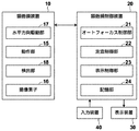
顕微鏡装置10は、観察対象である培養された細胞の位相差画像を撮像するものである。具体的には、顕微鏡装置10は、図1に示すように、白色光を出射する白色光源11、コンデンサレンズ12、スリット板13、結像光学系14、動作部15、撮像素子16、および検出部18を備える。また、顕微鏡装置10は、焦点距離変更光学系70を備える。
The
動作部15は、第1の動作部15A、第2の動作部15B、第3の動作部15C、第4の動作部15D、第5の動作部15E、第6の動作部15Fおよび第7の動作部15Gを備える。第1〜第7の動作部15A〜15Gの動作は後述する。
The operating
また、スリット板13と結像光学系14および検出部18との間に、ステージ51が設けられている。ステージ51上には、観察対象である細胞が収容された培養容器50が設置される。図2は、ステージ51の一例を示す図である。ステージ51の中央には、矩形の開口51aが形成されている。この開口51aを形成する部材の上に培養容器50が設置され、培養容器50内の細胞の位相差画像が開口51aを通過するように構成されている。
Further, a
本実施形態においては、培養容器50として、細胞が収容される複数のウェル(1つのウェルが、本開示の容器に相当する)を備えたウェルプレートを用いる。また、培養容器50に収容される細胞としては、iPS細胞およびES細胞といった多能性幹細胞、幹細胞から分化誘導された神経、皮膚、心筋および肝臓の細胞、並びに人体から取り出された皮膚、網膜、心筋、血球、神経および臓器の細胞等がある。
In the present embodiment, as the
ステージ51は、水平方向駆動部17(図8参照)によって互いに直交するX方向およびY方向に移動するものである。X方向およびY方向は、Z方向に直交する方向であり、水平面内において互いに直交する方向である。
The
スリット板13は、白色光源11から出射された白色光を遮光する遮光板に対して白色光を透過するリング形状のスリットが設けられたものであり、白色光がスリットを通過することによってリング状の照明光Lが形成される。
The
図3は、結像光学系14の詳細な構成を示す図である。結像光学系14は、図3に示すように、位相差レンズ14aおよび結像レンズ14dを備える。そして、位相差レンズ14aは、対物レンズ14bおよび位相板14cを備える。位相板14cは、照明光Lの波長に対して透明な透明板に対して位相リングを形成したものである。なお、上述したスリット板13のスリットの大きさは、位相板14cの位相リングと共役な関係にある。
FIG. 3 is a diagram showing a detailed configuration of the imaging
位相リングは、入射された光の位相を1/4波長ずらす位相膜と、入射された光を減光する減光フィルタとがリング状に形成されたものである。位相リングに入射された直接光は、位相リングを通過することによって位相が1/4波長ずれ、かつその明るさが弱められる。一方、観察対象によって回折された回折光は大部分が位相板14cの透明板を通過し、その位相および明るさは変化しない。
The phase ring is formed by forming a ring-shaped phase film that shifts the phase of the incident light by 1/4 wavelength and a dimming filter that dims the incident light. The direct light incident on the phase ring is shifted in phase by 1/4 wavelength and its brightness is weakened by passing through the phase ring. On the other hand, most of the diffracted light diffracted by the observation target passes through the transparent plate of the
対物レンズ14bを有する位相差レンズ14aは、図1に示す動作部15の第5の動作部15Eによって、対物レンズ14bの光軸方向に移動される。第5の動作部15Eは、例えば圧電素子等のアクチュエータを備える。なお、本実施形態においては、対物レンズ14bの光軸方向とZ方向(鉛直方向)とは同じ方向である。対物レンズ14bのZ方向への移動によってオートフォーカス制御が行われ、撮像素子16によって撮像される位相差画像のコントラストが調整される。
The
また、位相差レンズ14aの倍率を変更可能な構成としてもよい。具体的には、異なる倍率を有する位相差レンズ14aまたは結像光学系14を交換可能に構成するようにしてもよい。位相差レンズ14aまたは結像光学系14の交換は、自動的に行うようにしてもよいし、ユーザが手動で行うようにしてもよい。
Further, the magnification of the
また、対物レンズ14bは、焦点距離を変更可能な液体レンズからなる。なお、焦点距離を変更可能であれば、液体レンズに限定されるものではなく、液晶レンズおよび形状変形レンズ等、任意のレンズを用いることができる。対物レンズ14bは、図1に示す動作部15における第6の動作部15Fによって、印加される電圧が変更されて、焦点距離が変更される。これにより、結像光学系14の焦点距離が変更される。対物レンズ14bの焦点距離の変更によってもオートフォーカス制御が行われ、撮像素子16によって撮像される位相差画像のコントラストが調整される。
Further, the
結像レンズ14dは、位相差レンズ14aを通過した位相差画像が入射され、これを撮像素子16に結像する。本実施形態において、結像レンズ14dは、焦点距離を変更可能な液体レンズからなる。なお、焦点距離を変更可能であれば、液体レンズに限定されるものではなく、液晶レンズおよび形状変形レンズ等、任意のレンズを用いることができる。結像レンズ14dは、図1に示す動作部15における第1の動作部15Aによって、印加される電圧が変更されて、焦点距離が変更される。これにより、結像光学系14の焦点距離が変更される。結像レンズ14dの焦点距離の変更によってもオートフォーカス制御が行われ、撮像素子16によって撮像される位相差画像のコントラストが調整される。
A retardation image that has passed through the
また、結像レンズ14dは、図1に示す動作部15における第2の動作部15Bによって結像レンズ14dの光軸方向に移動される。第2の動作部15Bは、例えば圧電素子等のアクチュエータを備える。なお、本実施形態においては、結像レンズ14dの光軸方向とZ方向(鉛直方向)とは同じ方向である。結像レンズ14dのZ方向への移動によってオートフォーカス制御が行われ、撮像素子16によって撮像される位相差画像のコントラストが調整される。
Further, the
撮像素子16は、結像レンズ14dによって結像された位相差画像を撮像する。撮像素子16としては、CCD(Charge-Coupled Device)イメージセンサまたはCMOS(Complementary Metal-Oxide Semiconductor)イメージセンサ等が用いられる。撮像素子としては、RGB(Red Green Blue)のカラーフィルタが設けられた撮像素子を用いてもよいし、モノクロの撮像素子を用いるようにしてもよい。
The
また、撮像素子16は、図1に示す動作部15における第3の動作部15CによってZ方向に移動される。第3の動作部15Cは、例えば圧電素子等のアクチュエータを備える。なお、本実施形態においては、撮像素子16の撮像面に垂直な方向とZ方向とは同じ方向である。撮像素子16のZ方向への移動によってもオートフォーカス制御が行われ、撮像素子16によって撮像される位相差画像のコントラストが調整される。
Further, the
また、ステージ51は、第4の動作部15DによってZ方向に移動され、これにより、培養容器50がZ方向に移動される。第4の動作部15Dは、例えば圧電素子等のアクチュエータを備える。本実施形態においては、ステージ51における培養容器50が設置される面に垂直な方向とZ方向とは同じ方向である。ステージ51のZ方向への移動によってもオートフォーカス制御が行われ、撮像素子16によって撮像される位相差画像のコントラストが調整される。
Further, the
図4は焦点距離変更光学系の構成を示す概略図である。図4に示すように、焦点距離変更光学系70は、円形の第1のウェッジプリズム71および円形の第2のウェッジプリズム72を備える。第7の動作部15Gは、第1のウェッジプリズム71および第2のウェッジプリズム72を、互いに反対方向に同期させて移動させる。これにより、結像光学系14の焦点位置が変更される。焦点位置が変更されることは、焦点距離が長くなったり短くなったりすることと同義である。このため、結像光学系14の焦点位置が変更されることにより、結像光学系の14の焦点距離が変更される。本実施形態においては、結像光学系14の焦点距離を変更することは、第1の動作部15Aにより結像レンズ14dの焦点距離を変更すること、および第6の動作部15Fにより対物レンズ14bの焦点距離を変更することのみならず、第7の動作部15Gにより結像光学系14の焦点位置を変更することにより、結像光学系14の焦点距離を変更することも含む。
FIG. 4 is a schematic view showing the configuration of the focal length changing optical system. As shown in FIG. 4, the focal length changing
第1および第2のウェッジプリズム71,72は、光の入射面および出射面となり得る2つの面が平行でない、すなわち一方の面に対して他方の面が傾斜しているプリズムである。なお、以降の説明においては、光軸に対して垂直に配置される面を直角面、光軸に対して傾斜して配置される面をウェッジ面と称する。ウェッジプリズム71,72は、直角面に垂直に入射した光を偏向させるプリズムである。第7の動作部15Gは、例えば圧電素子等のアクチュエータを備え、後述する動作制御部21から出力された制御信号に基づいて、第1のウェッジプリズム71および第2のウェッジプリズム72を、直角面を平行に維持しつつ、互いに反対方向に同期させて移動させる。すなわち、第1のウェッジプリズム71を図4における右方向に移動させる場合には、第2のウェッジプリズム72を左方向に移動させる。逆に、第1のウェッジプリズム71を図4における左方向に移動させる場合には、第2のウェッジプリズム72を右方向に移動させる。このように、第1および第2のウェッジプリズム71,72を移動させることにより、結像光学系14から出射された光の光路長が変更され、これにより、結像光学系14の焦点位置を変更して焦点距離を変更することができる。これにより、オートフォーカス制御が行われ、撮像素子16によって撮像される位相差画像のコントラストが調整される。
The first and
検出部18は、ステージ51に設置された培養容器50のZ方向(鉛直方向)の位置を検出するものである。検出部18は、具体的には、第1のオートフォーカス用変位センサ18aおよび第2のオートフォーカス用変位センサ18bを備える。なお、第1および第2のオートフォーカス用変位センサ18a、18bは、本開示の変位センサに相当するものである。
The
第1のオートフォーカス用変位センサ18aおよび第2のオートフォーカス用変位センサ18bは、結像光学系14を挟んで、図1に示すX方向に並べて設けられている。本実施形態における第1のオートフォーカス用変位センサ18aおよび第2のオートフォーカス用変位センサ18bはレーザ変位計であり、培養容器50にレーザ光を照射し、その反射光を検出することによって、培養容器50の底面のZ方向の位置を検出するものである。なお、培養容器50の底面とは、培養容器50の底部と観察対象である細胞との境界面であり、すなわち観察対象設置面である。
The first
検出部18によって検出された培養容器50のZ方向の位置情報は、オートフォーカス制御部21に出力され、オートフォーカス制御部21は、入力された位置情報に基づいて、動作部15を制御し、オートフォーカス制御を行う。
The Z-direction position information of the
より具体的には、本実施形態の顕微鏡装置10においては、結像光学系14がステージ51上の培養容器50の所定の観察位置に到達する前に、先行してその観察位置における培養容器50のZ方向の位置情報を第1または第2のオートフォーカス用変位センサ18a,18bによって検出し、結像光学系14が、上記観察位置に到達した際に、第1または第2のオートフォーカス用変位センサ18a,18bによって検出された位置情報に基づいて動作部15を制御し、オートフォーカス制御を行う。
More specifically, in the
ここで、本実施形態のように、培養容器50として複数のウェルを備えたウェルプレートを用いた場合、ウェルプレートにおける全ての観察位置について、従来のように、結像光学系14が各観察位置に到達した時点からオートフォーカス制御を行ったのでは、観察位置の走査方向に隣接するウェルの境界部分の直後の観察位置、すなわち隣接するウェルのうち走査方向前側のウェルの最初の観察位置のオートフォーカス制御を行う際、ウェル毎の底部の厚さの違いから、オートフォーカス制御に長い時間がかかってしまう。なお、上述した観察位置の走査方向とは、ステージ51の移動方向とは逆の方向である。
Here, when a well plate provided with a plurality of wells is used as the
図5は、複数のウェル52を備えた培養容器50(ウェルプレート)の一例の断面模式図である。図5に示す「D」が隣接するウェルの境界部分であり、「52a」がウェル52の底部である。なお、図4に示すように、各ウェル52の底部52aの厚さは、製造上のばらつきによって異なっている。
FIG. 5 is a schematic cross-sectional view of an example of a culture vessel 50 (well plate) provided with a plurality of
そして、ステージ51をX方向に往復移動させ、かつY方向に移動させながら2次元状に走査を行う場合には、結像光学系14は何度もウェル52の境界を通過するため、上述したようなウェル52の境界部分Dを跨ぐ際のオートフォーカス制御の時間のロスが大きいものとなる。
Then, when scanning is performed in a two-dimensional manner while reciprocating the
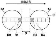
そこで、本実施形態においては、図6に示すように、隣接するウェル52の境界部分Dの直後の観察位置R2と境界部分Dの直後の観察位置R2以外の観察位置とで、オートフフォーカス制御を開始するタイミングを切り換える。具体的には、本実施形態においては、境界部分Dの直後の観察位置R2のオートフォーカス制御を、境界部分Dの直前の観察位置R1のオートフォーカス制御の終了時点から開始する。なお、図6における点線で示す矩形の範囲が各観察位置Rを示している。
Therefore, in the present embodiment, as shown in FIG. 6, the auto focus control is performed at the observation position R2 immediately after the boundary portion D of the
すなわち、本実施形態においては、隣接するウェル52の境界部分Dに含まれる観察位置については、オートフォーカス制御による撮像を行う必要がないので、この境界部分Dに含まれる観察位置についてはオートフォーカス制御を行わず、境界部分Dに含まれる観察位置の走査時間を利用して、境界部分Dの直後の観察位置R2のオートフォーカス制御を行う。図6は、ウェル52の境界部分Dの近傍の観察位置R0〜R3のオートフォーカス制御の開始タイミングと終了タイミングの一例を示す図である。図7に示すf0〜f3が、各観察位置R0〜R3のフォートフォーカス制御を行っている時間であり、Txは、隣接する観察位置の間の走査時間(結像光学系14がステージ51に対して相対的に移動する時間)であり、Tdは、観察位置R2から観察位置R3までの走査時間である。
That is, in the present embodiment, it is not necessary to perform imaging by autofocus control for the observation position included in the boundary portion D of the
図7に示すように、観察位置R0については、時刻t0からオートフォーカス制御が開始され、時刻t1の時点でオートフォーカス制御を終了する。そして、観察位置R0から観察位置R1まで走査された後、時刻t2から観察位置R1のオートフォーカス制御が開始され、時刻t3の時点でオートフォーカス制御を終了する。そして、観察位置R1のオートフォーカス制御を終了した時刻t3から観察位置R2のオートフォーカス制御を開始し、結像光学系14が観察位置R2に到達する時刻t5までの間の時刻t4において、観察位置R2のオートフォーカス制御を終了する。すなわち、観察位置R1から観察位置R2までの走査時間Tdの間に、観察位置R2のオートフォーカス制御を終了する。
As shown in FIG. 7, for the observation position R0, the autofocus control is started from the time t0, and the autofocus control is ended at the time t1. Then, after scanning from the observation position R0 to the observation position R1, the autofocus control of the observation position R1 is started from the time t2, and the autofocus control is ended at the time t3. Then, the autofocus control of the observation position R2 is started from the time t3 when the autofocus control of the observation position R1 is finished, and the observation position is at the time t4 between the time t5 when the imaging
そして、結像光学系14が観察位置R2に到達した時刻t5では、既に観察位置R2のオートフォーカス制御が終了しているので、即座に観察位置R2の位相差画像の撮像が行われ、次の観察位置R3に向かって走査される。そして、観察位置R2から観察位置R3まで走査された後、時刻t6から観察位置R3のオートフォーカス制御が開始され、時刻t7の時点でオートフォーカス制御を終了する。
Then, at the time t5 when the imaging
従来のオートフォーカス制御の場合、結像光学系14が、観察位置R2に到達した時点(図7の時刻t5)から観察位置R2のオートフォーカス制御が開始されるので、その分撮影時間が長くなり、特に、ウェル52の底部の厚さが異なる場合には、その時間のロスが大きくなる。
In the case of the conventional autofocus control, the autofocus control of the observation position R2 is started from the time when the imaging
本実施形態では、上述したように境界部分Dの直後の観察位置R2のオートフォーカス制御の開始タイミングを早くすることによって、撮影時間の短縮を図ることができる。 In the present embodiment, as described above, the shooting time can be shortened by accelerating the start timing of the autofocus control of the observation position R2 immediately after the boundary portion D.
なお、境界部分Dの直後の観察位置R2以外の観察位置については、上述したように、各観察位置に到達した時点からオートフォーカス制御を開始する。また、本実施形態においては、境界部分Dの直後の観察位置R2のオートフォーカス制御を、境界部分Dの直前の観察位置R1のオートフォーカス制御の終了時点t3から開始するようにしたが、これに限らず、観察位置Rのオートフォーカス制御の終了時点t3から結像光学系14が観察位置R2に到達する時刻t5の前であれば、その他の時点でもよい。すなわち、図7に示すTdの間であればその他の時点でもよい。
As for the observation positions other than the observation position R2 immediately after the boundary portion D, the autofocus control is started from the time when each observation position is reached, as described above. Further, in the present embodiment, the autofocus control of the observation position R2 immediately after the boundary portion D is started from the end time t3 of the autofocus control of the observation position R1 immediately before the boundary portion D. Not limited to this, any time may be used as long as it is before the time t5 when the imaging
また、本実施形態においては、境界部分Dの直後の観察位置R2以外の観察位置のオートフォーカス制御のための時間(例えば図7に示す時刻t0〜時刻t2までの時間であり、結像光学系14が観察位置R0に到達した時点から観察位置R1に到達するまでの時間)よりも、境界部分Dの直後の観察位置R2のオートフォーカス制御のための時間(例えば図7に示すTdの時間であり、結像光学系14が観察位置R1から観察位置R2に到達するまでの時間)の方が長くなるように設定されている。
Further, in the present embodiment, the time for autofocus control of the observation position other than the observation position R2 immediately after the boundary portion D (for example, the time from the time t to the time t2 shown in FIG. 7, is the time, and is the imaging optical system. The time for autofocus control of the observation position R2 immediately after the boundary portion D (for example, the time of Td shown in FIG. 7) rather than the time from the time when 14 reaches the observation position R0 to the time when it reaches the observation position R1). The time it takes for the imaging
また、上述したような境界部分Dの直後の観察位置R2のオートフォーカス制御を行う場合、境界部分Dの直前の観察位置R1と境界部分Dの直後の観察位置R2のX−Y平面内における座標位置を特定する必要がある。すなわち、境界部分Dを特定する必要がある。そこで、本実施形態においては、上述した第1または第2のオートフォーカス用変位センサ18a,18bによって隣接するウェル52の境界部分Dを検出する。具体的には、境界部分Dには、ウェル52の底面が存在しないので、明らかに第1または第2のオートフォーカス用変位センサ18a,18bによって検出される検出信号が異なるものとなる。したがって、例えば第1または第2のオートフォーカス用変位センサ18a,18bによって検出された検出信号が、予め設定された閾値の範囲内であるかを判定することによって、境界部分Dを検出することができる。
Further, when the autofocus control of the observation position R2 immediately after the boundary portion D as described above is performed, the coordinates of the observation position R1 immediately before the boundary portion D and the observation position R2 immediately after the boundary portion D in the XY plane. It is necessary to specify the position. That is, it is necessary to specify the boundary portion D. Therefore, in the present embodiment, the boundary portion D of the
次に、顕微鏡装置10を制御する顕微鏡制御装置20の構成について説明する。図8は、本実施形態の顕微鏡観察システムの構成を示すブロック図である。なお、顕微鏡装置10については、顕微鏡制御装置20の各部により制御される一部の構成のブロック図を示している。
Next, the configuration of the
顕微鏡制御装置20は、顕微鏡装置10全体を制御するものであり、特に、オートフォーカス制御部21、走査制御部22および表示制御部23を備える。
The
顕微鏡制御装置20は、中央処理装置、半導体メモリおよびハードディスク等を備えたコンピュータから構成されるものであり、ハードディスクに本開示の観察装置制御プログラムの一実施形態がインストールされている。そして、この観察装置制御プログラムが中央処理装置によって実行されることによって、図8に示すオートフォーカス制御部21、走査制御部22および表示制御部23が機能する。
The
オートフォーカス制御部21は、上述したように検出部18によって検出された培養容器50のZ方向の位置情報に基づいて、動作部15を動作させてオートフォーカス制御を行う。また、本実施形態のオートフォーカス制御部21は、上述したように、隣接するウェルの境界部分の直後の観察位置と境界部分の直後の観察位置以外の観察位置とで、オートフォーカス制御を開始するタイミングを切り換える。
The
ここで、オートフォーカス制御部21には、培養容器50のZ方向の位置情報と、結像レンズ14dの焦点距離を変更するための結像レンズ14dへの印加電圧、結像レンズ14dの光軸方向の移動量、撮像素子16の光軸方向の移動量、ステージ51の光軸方向の移動量、対物レンズ14bの光軸方向の移動量、対物レンズ14bの焦点距離を変更するための対物レンズ14bへの印加電圧、および焦点距離変更光学系70の移動量との関係が、予めテーブルとして記憶されている。このテーブルを第1のテーブルと称する。
Here, the
オートフォーカス制御部21は、入力された培養容器50のZ方向の位置情報に基づいて、第1のテーブルを参照して、結像レンズ14dの焦点距離を変更するための結像レンズ14dへの印加電圧、結像レンズ14dの光軸方向の移動量、撮像素子16の光軸方向の移動量、ステージ51の光軸方向の移動量、対物レンズ14bの光軸方向の移動量、対物レンズ14bの焦点距離を変更するための対物レンズ14bへの印加電圧、および焦点距離変更光学系70の移動量をそれぞれ求める。なお、以降の説明においては、結像レンズ14dの焦点距離を変更するための結像レンズ14dへの印加電圧、結像レンズ14dの光軸方向の移動量、撮像素子16の光軸方向の移動量、ステージ51の光軸方向の移動量、対物レンズ14bの光軸方向の移動量、対物レンズ14bの焦点距離を変更するための対物レンズ14bへの印加電圧、および焦点距離変更光学系70の移動量をフォーカス制御量と称する。
The
オートフォーカス制御部21は、動作部15を制御するために、フォーカス制御量に応じた制御信号を、第1の動作部15A〜第7の動作部15Gに出力する。具体的には、後述するように取得されたステージ51の位置情報に基づいて第1のテーブルが参照されて、フォーカス制御量が取得される。これにより、第1の動作部15Aにより結像レンズ14dの焦点距離が変更されて結像光学系14の焦点距離が変更される。また、第2の動作部15Bにより結像レンズ14dが光軸方向に移動する。また、第3の動作部15Cにより撮像素子16が光軸方向に移動する。また、第4の動作部15Dによりステージ51が光軸方向に移動する。また、第5の動作部15Eにより対物レンズ14bが光軸方向に移動する。第6の動作部15Fにより対物レンズ14bの焦点距離が変更されて結像光学系14の焦点距離が変更される。さらに、第7の動作部15Gにより結像光学系14の焦点位置が変更されて、結像光学系14の焦点距離が変更される。これらの7つの動作により、オートフォーカス制御が行われる。
In order to control the
なお、第1の動作部15Aによる結像レンズ14dの焦点距離の変更、第6の動作部15Fによる対物レンズ14bの焦点距離の変更、および第7の動作部15Gによる焦点距離変更光学系70による焦点距離の変更が、第1の動作に対応する。また、第2の動作部15Bによる結像レンズ14dの光軸方向への移動が第2の動作に対応する。また、第3の動作部15Cによる撮像素子16の光軸方向への移動が第3の動作に対応する。また、第4の動作部15Dによるステージ51の光軸方向への移動が第4の動作に対応する。また、第5の動作部15Eによる対物レンズ14bの光軸方向への移動が第5の動作に対応する。
The focal length of the
走査制御部22は、水平方向駆動部17を駆動制御し、これによりステージ51をX方向およびY方向に移動させて、培養容器50をX方向およびY方向に移動させる。水平方向駆動部17は、圧電素子等のアクチュエータから構成される。
The
本実施形態においては、上述したように走査制御部22による制御によってステージ51をX方向およびY方向に移動させ、培養容器50内における観察位置を2次元状に走査し、各観察位置の位相差画像を撮像する。図9は、培養容器50内における観察位置の走査位置を実線Mで示した図である。なお、本実施形態においては、培養容器50として6つのウェル52を有するウェルプレートを用いる。
In the present embodiment, as described above, the
図9に示すように、培養容器50において、観察位置は、ステージ51のX方向およびY方向の移動によって走査開始点Sから走査終了点Eまで実線Mに沿って走査される。すなわち、観察位置は、X方向の正方向(図9の右方向)に走査された後、Y方向(図9の下方向)に走査され、逆の負方向(図9の左方向)に走査される。次いで、観察位置は、再びY方向に走査され、再びX方向の正方向に走査される。このように、ステージ51のX方向についての往復移動とY方向への移動を繰り返し行うことによって、観察位置は、培養容器50内を2次元状に走査される。
As shown in FIG. 9, in the
次に、図8に戻り、表示制御部23は、顕微鏡装置10によって撮像された各観察位置の位相差画像を結合することによって、1枚の合成位相差画像を生成し、その合成位相差画像を表示装置30に表示させるものである。
Next, returning to FIG. 8, the
表示装置30は、上述したように表示制御部23によって生成された合成位相差画像を表示するものであり、例えば液晶ディスプレイ等を備える。また、表示装置30をタッチパネルによって構成し、入力装置40と兼用するようにしてもよい。
The
入力装置40は、マウスおよびキーボード等を備え、ユーザによる種々の設定入力を受け付ける。本実施形態の入力装置40は、例えば位相差レンズ14aの倍率の変更指示およびステージ51の移動速度の変更指示等の設定入力を受け付ける。
The
次に、本実施形態の顕微鏡観察システムの作用について、図10に示すフローチャートを参照しながら説明する。まず、観察対象である細胞が収容された培養容器50が、ステージ51上に設置される(ステップST10)。次に、ステージ51が移動して結像光学系14の観察位置が、図9に示す走査開始点Sの位置に設定され、ステージ51の移動が開始される(ステップST12)。
Next, the operation of the microscope observation system of the present embodiment will be described with reference to the flowchart shown in FIG. First, the
ここで、本実施形態においては、上述したように各観察位置について、先行して培養容器50のZ方向の位置検出が行われ、その観察位置まで結像光学系14が移動した時点において、位相差画像の撮像が行われる。そして、この培養容器50のZ方向の位置検出と位相差画像の撮像は、観察位置を走査しながら行われ、ある観察位置の位相差画像の撮像と、その観察位置よりも走査方向について前側の位置における培養容器50のZ方向の位置検出とが並行して行わる。
Here, in the present embodiment, as described above, the position of the
具体的には、図11の矢印方向にステージ51が往路移動している場合には、第1のオートフォーカス用変位センサ18aによって培養容器50のZ方向の位置が検出され(ステップST14)、その検出された位置情報が、オートフォーカス制御部21によって取得される。オートフォーカス制御部21は、取得した培養容器50のZ方向の位置情報を、培養容器50の観察位置のX−Y座標とともに記憶する。
Specifically, when the
さらに、第1のオートフォーカス用変位センサ18aは、各観察位置の培養容器50のZ方向の位置検出と並行して、ウェルの境界部分の検出処理を行う(ステップST16)。そして、ウェルの境界部分が検出された場合には、そのX−Y座標を記憶する。
Further, the first
次いで、ステップST14において第1のオートフォーカス用変位センサ18aによって培養容器50の位置検出が行われた観察位置に向かって結像光学系14が移動し、その観察位置のオートフォーカス制御が行われるが、上述したように観察位置によってオートフォーカス制御の開始タイミングを切り換える。
Next, in step ST14, the imaging
具体的には、観察位置が、隣接するウェルの境界部分に到達していない場合には(ステップST18;NO)、各観察位置に到達した時点からオートフォーカス制御を開始する(ステップST20)。具体的には、各観察位置における培養容器50のZ方向の位置情報に基づいて、フォーカス制御量を取得し、フォーカス制御量に基づいてオートフォーカス制御を行う。
Specifically, when the observation position does not reach the boundary portion of the adjacent well (step ST18; NO), the autofocus control is started from the time when each observation position is reached (step ST20). Specifically, the focus control amount is acquired based on the position information of the
一方、隣接するウェルの境界部分の直前の観察位置に到達した場合には、その観察位置のオートフォーカス制御が終了した時点から、次のウェルの境界部分の直後の観察位置(次のウェルの最初の観察位置)のオートフォーカス制御を開始する(ステップST22)。すなわち、境界部分の直後の観察位置における培養容器50のZ方向の位置情報に基づいて、フォーカス制御量を取得し、フォーカス制御量に基づいてオートフォーカス制御を行う。
On the other hand, when the observation position immediately before the boundary portion of the adjacent well is reached, the observation position immediately after the boundary portion of the next well (the beginning of the next well) from the time when the autofocus control of the observation position is completed. The autofocus control of the observation position) is started (step ST22). That is, the focus control amount is acquired based on the position information of the
そして、各観察位置についてオートフォーカス制御が終了した後(ステップST24)、位相差画像の撮像を行う(ステップST26)。各観察位置の位相差画像は、撮像素子16から表示制御部23に出力されて記憶される。
Then, after the autofocus control is completed for each observation position (step ST24), the phase difference image is captured (step ST26). The phase difference image of each observation position is output from the
そして、往路移動が終了し、図12に示すように復路移動に切り換えられた場合には、使用する変位センサが第1のオートフォーカス用変位センサ18aから第2のオートフォーカス用変位センサ18bに切り換えられる。
Then, when the outward movement is completed and the movement is switched to the return movement as shown in FIG. 12, the displacement sensor used is switched from the first
そして、この時点において、全ての走査が終了していない場合には(ステップST28;NO)、ステージ51が復路移動し、ステップST14〜ST28の処理が行われる。
Then, at this point in time, if all the scans have not been completed (step ST28; NO), the
ステージ51の移動方向が切り換えられる度に使用する変位センサが切り換えられ、全ての走査が終了するまでステップST14〜ST26までの処理が繰り返して行われる。そして、観察位置が、図9に示す走査終了点Eの位置に到達した時点において全ての走査が終了する(ステップST28;YES)。
Each time the moving direction of the
全ての走査が終了した後、表示制御部23は、各観察位置Rの位相差画像を結合して合成位相差画像を生成し(ステップST30)、生成した合成位相差画像を表示装置30に表示させる(ステップST32)。
After all the scanning is completed, the
上記実施形態の顕微鏡観察システムによれば、培養容器50内の観察位置毎のオートフォーカス制御を行う際、観察位置の走査方向に隣接するウェル52の境界部分Dに基づいて、観察位置毎のオートフォーカス制御の開始タイミングを切り換えるようにしたので、オートフォーカス制御をより効率的に行い、撮影時間の短縮を図ることができる。
According to the microscope observation system of the above embodiment, when autofocus control is performed for each observation position in the
また、第1から第7の動作部15A〜15Gによりオートフォーカス制御を行っているため、1つの動作のみでオートフォーカス制御を行う場合よりも、オートフォーカス制御を高速に行うことができる。
Further, since the autofocus control is performed by the first to
なお、上記実施形態においては、ウェルの境界部分を第1または第2のオートフォーカス用変位センサ18a,18bによって検出するようにしたが、これに限らず、ウェルの境界部分を予め取得して記憶しておいてもよい。具体的には、図13に示すように、ウェルの境界部分の位置情報を記憶する記憶部24を設け、オートフォーカス制御部21が、記憶部24に記憶された境界部分の位置情報に基づいて、オートフォーカス制御の開始タイミングを切り換えるようにしてもよい。
In the above embodiment, the boundary portion of the well is detected by the first or
また、このようにウェルの境界部分の位置情報を記憶する場合には、培養容器50毎に識別情報を付与し、その識別情報とウェルの境界部分の位置情報を対応付けたテーブル(以下第2のテーブルとする)を予め設定しておいてもよい。このような第2のテーブルを設けることによって、例えばウェルの数が異なる培養容器50が設置された場合でも、上述したようなオートフォーカス制御の開始タイミングの切り換えを適切に行うことができる。なお、培養容器50の識別情報については、ユーザが入力装置40を用いて設定入力するようにしてもよいし、培養容器50に対し、識別情報が記憶されたバーコードまたはRFID(Radio frequency identification)タグを設け、これらから識別情報を読み出すようにしてもよい。
Further, when the position information of the boundary portion of the well is stored in this way, identification information is given to each
また、上記実施形態の顕微鏡観察システムにおいては、第1および第2のオートフォーカス用変位センサ18a,18bを用いてウェルの境界部分を検出するようにしたが、これに限らず、第1および第2のオートフォーカス用変位センサ18a,18bの他にウェル境界検出用のセンサを設けるようにしてもよい。
Further, in the microscope observation system of the above embodiment, the first and second
また、上記実施形態の顕微鏡観察システムにおいては、培養容器50として複数のウェル52を有するウェルプレートを用いるようにしたが、本開示の容器としてシャーレを用い、複数のシャーレをステージ51上に設置するようにしてもよい。上記実施形態においては、観察位置の走査方向に隣接するウェル52の境界部分に基づいて、観察位置毎のオートフォーカス制御の開始タイミングを切り換えるようにしたが、複数のシャーレをステージ51上に設置する場合には、観察位置の走査方向に隣接するシャーレの境界部分に基づいて、観察位置毎のオートフォーカス制御の開始タイミングを切り換えるようにすればよい。
Further, in the microscope observation system of the above embodiment, a well plate having a plurality of
具体的には、上述したウェル52をシャーレに置き換えればよく、シャーレの境界部分の直後の観察位置のオートフォーカス制御を、例えば境界部分の直前の観察位置のオートフォーカス制御の終了時点から開始するようにすればよい。そして、境界部分の直後以外の観察位置については、その観察位置に結像光学系14が到達した時点からオートフォーカス制御を開始するようにすればよい。
Specifically, the well 52 described above may be replaced with a petri dish, and the autofocus control of the observation position immediately after the boundary portion of the petri dish may be started from the end of the autofocus control of the observation position immediately before the boundary portion, for example. It should be. Then, for the observation position other than immediately after the boundary portion, the autofocus control may be started from the time when the imaging
また、上記実施形態においては、培養容器50の底面のZ方向の位置を検出するようにしたが、例えば、培養容器50の底面にキズまたは汚れの付着等があり、検出部18によって検出される検出信号が異常である場合には、適切なオートフォーカス制御を行うことができない。図14は、培養容器50の底面にキズまたは汚れの付着等がある場合において、検出部18によって検出された検出信号に基づくZ方向の位置を示す図である。図14に示すS1の範囲は、各ウェル52の底面の範囲であり、S3の範囲は、ウェル52の境界部分Dの範囲である。そして、図14に示すS2の範囲が、培養容器50の底面におけるキズまたは汚れの付着の範囲である。
Further, in the above embodiment, the position of the bottom surface of the
そこで、オートフォーカス制御部21が、検出部18によって検出された検出信号が異常である場合には、その異常な検出信号が検出された観察位置については、その観察位置の走査方向について前後の観察位置の検出部18の検出信号に基づくオートフォーカス制御を行うようにしてもよい。図14に示すような検出信号の場合には、S2の範囲については検出部18によって検出された検出信号を用いず、S2の範囲の直前および/または直後の観察位置の検出信号を用いてオートフォーカス制御を行う。
Therefore, when the detection signal detected by the
具体的には、例えばS2の範囲の直前の観察位置の検出信号と直後の観察位置の検出信号の平均値を用いて、S2の範囲の観察位置のオートフォーカス制御を行うようにすればよい。また、平均値に限らず、S2の範囲の直前の観察位置の検出信号または直後の観察位置の検出信号を用いるようにしてもよいし、S2の範囲の直前の観察位置の検出信号と直後の観察位置の検出信号とを用いて線形補間を行って、S2の範囲の観察位置の検出信号を取得するようにしてもよい。また、S2の範囲の直前および直後の観察位置だけでなく、S2の範囲の前の2以上の観察位置の検出信号と、S2の範囲の後の2以上の観察位置の検出信号とを用いて線形補間を行うことによって、S2の範囲の検出信号を取得するようにしてもよい。 Specifically, for example, the autofocus control of the observation position in the range of S2 may be performed by using the average value of the detection signal of the observation position immediately before the range of S2 and the detection signal of the observation position immediately after the range of S2. Further, not limited to the average value, the detection signal of the observation position immediately before the range of S2 or the detection signal of the observation position immediately after may be used, or the detection signal of the observation position immediately before and immediately after the range of S2. Linear interpolation may be performed using the detection signal of the observation position to acquire the detection signal of the observation position in the range of S2. Further, not only the observation positions immediately before and after the S2 range, but also the detection signals of the two or more observation positions before the S2 range and the detection signals of the two or more observation positions after the S2 range are used. The detection signal in the range of S2 may be acquired by performing linear interpolation.
なお、上記実施形態においては、ステージ51を移動させることによって、培養容器50内の観察位置を走査するようにしたが、これに限らず、結像光学系14、検出部18および撮像素子16からなる撮影系を移動させるようにしてもよい。また、ステージ51と撮影系との両方を移動させるようにしてもよい。
In the above embodiment, the observation position in the
また、上記実施形態においては、動作部15が第1〜第7の動作部15A〜15Gによりオートフォーカス制御を行っているが、第1〜第4の動作部15A〜15Dおよび第6〜第7の動作部15F,15Gのみを備えるものとしてもよい。また、第1〜第4の動作部15A〜15Dおよび第6〜第7の動作部15F,15Gのうちのいずれか1つのみを用いてオートフォーカス制御を行うようにしてもよい。この場合、さらに第5の動作部15Eを用いてオートフォーカス制御を行うようにしてもよい。また、第1〜第4の動作部15A〜15Dおよび第6〜第7の動作部15F,15Gのうちのいずれか1つのみを備えるものとしてもよい。この場合においても、さらに第5の動作部15Eを備えるものとし、第5の動作部15Eをさらに用いてオートフォーカス制御を行うようにしてもよい。また、第1〜第4の動作部15A〜15Dおよび第6〜第7の動作部15F,15Gのうちの、複数の動作部を用いてオートフォーカス制御を行うようにしてもよい。この場合も、さらに第5の動作部15Eを用いてオートフォーカス制御を行うようにしてもよい。
Further, in the above embodiment, the operating
また、上記実施形態においては、焦点距離変更光学系70を、結像光学系14と撮像素子16との間に配置しているが、結像光学系14とステージ51との間に配置してもよい。
Further, in the above embodiment, the focal length changing
また、上記実施形態においては、第1の動作部15A、第6の動作部15Fおよび第7の動作部15Gにより、結像光学系14の焦点距離を変更しているが、第1の動作部15A、第6の動作部15Fおよび第7の動作部15Gのうちのいずれか1つまたはいずれか2つのみにより、結像光学系14の焦点距離を変更してもよい。
Further, in the above embodiment, the focal length of the imaging
また、上記実施形態においては、第4の動作部15Dによりステージ51を光軸方向に移動させることにより、培養容器50を光軸方向に移動させている。しかしながら、ステージ51を光軸方向に移動させることに代えて、培養容器50を光軸方向に移動させる機構を設け、培養容器50のみを光軸方向に移動させるようにしてもよい。
Further, in the above embodiment, the
また、上記実施形態においては、結像光学系14の焦点距離を変更するための焦点距離変更光学系70として、第1および第2のウェッジプリズム71,72を移動させる光学系を用いている。しかしながら、液体レンズ、液晶レンズおよび形状変形レンズ等の焦点距離を変更可能な光学素子を、焦点距離変更光学系として用いてもよい。例えば、第1および第2のウェッジプリズム71,72を移動させる焦点距離変更光学系70に代えて、図15に示すように、結像光学系14と撮像素子16との間に、焦点距離を変更可能な光学素子からなる焦点距離変更光学系75を配置してもよい。この場合、焦点距離変更光学系75は、第8の動作部15Hにより、印加される電圧が変更されて、焦点距離が変更されることとなる。なお、焦点距離変更光学系75は、結像光学系14とステージ51との間に配置してもよい。また、焦点距離変更光学系75は、焦点距離変更光学系70に加えて配置してもよい。
Further, in the above embodiment, as the focal length changing
また、上記実施形態においては、第1のオートフォーカス用変位センサ18aおよび第2のオートフォーカス用変位センサ18bを位相差レンズ14aを挟んでX方向に並べて設けているが、さらに図16に示すように、第3のオートフォーカス用変位センサ18cおよび第4のオートフォーカス用変位センサ18dを、位相差レンズ14aを挟んでY方向に並べて設けるようにしてもよい。
Further, in the above embodiment, the first
これにより、観察域Rを往復移動するのみならず、図17に示すように移動することができる。すなわち、図17においては、観察域Rは走査開始点SからX方向の正方向(図17の右方向)に移動された後、Y方向の正方向(図17の下方向)に移動され、次いで、X方向の負方向(図17の左方向)に移動され、さらにY方向の負方向(図17の上方向)に移動される。このように、観察域RのX方向およびY方向の移動を繰り返し行うことによっても、培養容器50内を2次元状に走査することができる。この場合に、ウェルの境界部分を第1および第2のオートフォーカス用変位センサ18a,18bに加えて、第3および第4のオートフォーカス用変位センサ18c,18dによって検出することができる。
As a result, not only the observation area R can be reciprocated, but also the observation area R can be moved as shown in FIG. That is, in FIG. 17, the observation area R is moved from the scanning start point S in the positive direction in the X direction (right direction in FIG. 17) and then in the positive direction in the Y direction (downward in FIG. 17). Then, it is moved in the negative direction in the X direction (left direction in FIG. 17), and further moved in the negative direction in the Y direction (upward direction in FIG. 17). By repeatedly moving the observation area R in the X and Y directions in this way, the inside of the
また、上記実施形態は、本開示を位相差顕微鏡に適用したものであるが、本開示は、位相差顕微鏡に限らず、微分干渉顕微鏡および明視野顕微鏡等のその他の顕微鏡に適用するようにしてもよい。 Further, although the above embodiment applies the present disclosure to a phase-contrast microscope, the present disclosure is not limited to a phase-contrast microscope, but is applied to other microscopes such as a differential interference microscope and a brightfield microscope. May be good.
また、上記実施形態においては、結像光学系14によって結像された位相差画像を撮像素子16によって撮像するようにしたが、撮像素子を設けることなく、結像光学系14によって結像された観察対象の位相差像をユーザが直接観察できるように観察光学系等を設けるようにしてもよい。この場合、観察装置には、第1の動作部15A、第2の動作部15B、第4の動作部15D、および第6〜第7の動作部15F,15Gのうちの少なくとも1つを設けてオートフォーカス制御を行えばよい。また、この場合、さらに第5の動作部15Eを設けてオートフォーカス制御を行うようにしてもよい。また、焦点距離変更光学系70および第7の動作部15Gに代えて、焦点距離変更光学系75および第8の動作部15Hを設けてオートフォーカス制御を行うようにしてもよい。
Further, in the above embodiment, the phase difference image formed by the imaging
10 顕微鏡装置
11 白色光源
12 コンデンサレンズ
13 スリット板
14 結像光学系
14a 位相差レンズ
14b 対物レンズ
14c 位相板
14d 結像レンズ
15 動作部
15A 第1の動作部
15B 第2の動作部
15C 第3の動作部
15D 第4の動作部
15E 第5の動作部
15F 第6の動作部
15G 第7の動作部
15H 第8の動作部
16 撮像素子
17 水平方向駆動部
18 検出部
18a 第1のオートフォーカス用変位センサ
18b 第2のオートフォーカス用変位センサ
18c 第3のオートフォーカス用変位センサ
18d 第4のオートフォーカス用変位センサ
20 顕微鏡制御装置
21 オートフォーカス制御部
22 走査制御部
23 表示制御部
24 記憶部
30 表示装置
40 入力装置
50 培養容器
51 ステージ
51a 開口
52 ウェル
52a 底部
70,75 焦点距離変更光学系
71 第1のウェッジプリズム
72 第2のウェッジプリズム
D 境界部分
E 走査終了点
L 照明光
M 走査位置を示す実線
R 観察位置
R1 観察位置
R2 観察位置
S 走査開始点10
Claims (20)
前記結像光学系により結像された前記観察対象の画像を撮像する撮像素子を有する撮像系と、
前記結像光学系の焦点距離を変更する第1の動作、前記結像レンズを光軸方向に移動させる第2の動作、前記撮像素子を前記光軸方向に移動させる第3の動作、および前記容器を光軸方向に移動させる第4の動作の少なくとも1つを行う動作部と、
前記容器および前記結像光学系の少なくとも一方を水平面内において移動させる水平方向駆動部と、
該水平方向駆動部を制御して、前記容器および前記結像光学系の少なくとも一方を移動させることによって、前記容器内の観察位置を走査する走査制御部と、
前記動作部を制御して、前記観察位置毎のオートフォーカス制御を行うオートフォーカス制御部とを備え、
前記オートフォーカス制御部が、前記観察位置の走査方向に隣接する前記容器の境界部分に基づいて、前記観察位置毎のオートフォーカス制御の開始タイミングを切り換える観察装置。An imaging optical system having an imaging lens for forming an image of the observation object in a plurality of containers in which the observation object is housed, and an imaging optical system.
An imaging system having an imaging element that captures an image of the observation target imaged by the imaging optical system, and an imaging system.
The first operation of changing the focal length of the imaging optical system, the second operation of moving the imaging lens in the optical axis direction, the third operation of moving the image pickup element in the optical axis direction, and the above-mentioned An operating unit that performs at least one of the fourth operations of moving the container in the optical axis direction,
A horizontal drive unit that moves at least one of the container and the imaging optical system in a horizontal plane, and
A scanning control unit that scans an observation position in the container by controlling the horizontal drive unit and moving at least one of the container and the imaging optical system.
It is provided with an autofocus control unit that controls the operation unit and performs autofocus control for each observation position.
An observation device in which the autofocus control unit switches the start timing of autofocus control for each observation position based on the boundary portion of the container adjacent to the scanning direction of the observation position.
前記結像光学系の焦点距離を変更する第1の動作、前記結像レンズを光軸方向に移動させる第2の動作、および前記容器を光軸方向に移動させる第4の動作の少なくとも1つを行う動作部と、
前記容器および前記結像光学系の少なくとも一方を水平面内において移動させる水平方向駆動部と、
該水平方向駆動部を制御して、前記容器および前記結像光学系の少なくとも一方を移動させることによって、前記容器内の観察位置を走査する走査制御部と、
前記動作部を制御して、前記観察位置毎のオートフォーカス制御を行うオートフォーカス制御部とを備え、
前記オートフォーカス制御部が、前記観察位置の走査方向に隣接する前記容器の境界部分に基づいて、前記観察位置毎のオートフォーカス制御の開始タイミングを切り換える観察装置。An imaging optical system having an imaging lens for forming an image of the observation object in a plurality of containers in which the observation object is housed, and an imaging optical system.
At least one of a first operation of changing the focal length of the imaging optical system, a second operation of moving the imaging lens in the optical axis direction, and a fourth operation of moving the container in the optical axis direction. And the moving part that performs
A horizontal drive unit that moves at least one of the container and the imaging optical system in a horizontal plane, and
A scanning control unit that scans an observation position in the container by controlling the horizontal drive unit and moving at least one of the container and the imaging optical system.
It is provided with an autofocus control unit that controls the operation unit and performs autofocus control for each observation position.
An observation device in which the autofocus control unit switches the start timing of autofocus control for each observation position based on the boundary portion of the container adjacent to the scanning direction of the observation position.
前記第1の動作は、前記結像レンズの焦点距離を変更する動作および前記対物レンズの焦点距離を変更する動作の少なくとも一方を含む請求項1から4のいずれか1項に記載の観察装置。The imaging optical system further includes an objective lens that forms an image of the observation target in the container.
The observation device according to any one of claims 1 to 4, wherein the first operation includes at least one of an operation of changing the focal length of the imaging lens and an operation of changing the focal length of the objective lens.
前記結像光学系は、前記容器内の前記観察対象の像を結像させる対物レンズをさらに有し、
前記第1の動作は、前記結像レンズの焦点距離を変更する動作、前記対物レンズの焦点距離を変更する動作、および前記焦点距離変更光学系により、前記結像光学系の焦点距離を変更する動作の少なくとも1つを含む請求項1から4のいずれか1項に記載の観察装置。A focal length changing optical system for changing the focal length of the imaging optical system is further provided.
The imaging optical system further includes an objective lens that forms an image of the observation target in the container.
The first operation is an operation of changing the focal length of the imaging lens, an operation of changing the focal length of the objective lens, and an operation of changing the focal length of the imaging optical system by the focal length changing optical system. The observation device according to any one of claims 1 to 4, which comprises at least one operation.
前記第1の動作は、前記焦点距離変更光学系により、前記結像光学系の焦点距離を変更する動作を含む請求項1から4のいずれか1項に記載の観察装置。A focal length changing optical system for changing the focal length of the imaging optical system is further provided.
The observation device according to any one of claims 1 to 4, wherein the first operation includes an operation of changing the focal length of the imaging optical system by the focal length changing optical system.
前記動作部は、さらに前記対物レンズを前記光軸方向に移動させる第5の動作を行う請求項1から4および8のいずれか1項に記載の観察装置。The imaging optical system further includes an objective lens that forms an image of the observation target in the container.
The observation device according to any one of claims 1 to 4 and 8, wherein the moving unit further performs a fifth operation of moving the objective lens in the optical axis direction.
前記オートフォーカス制御部が、前記検出部の検出信号に基づいて、前記各観察位置のオートフォーカス制御を行う請求項1から12のいずれか1項に記載の観察装置。A detection unit for detecting the vertical position of the container at the observation position before the imaging optical system reaches the observation position is provided.
The observation device according to any one of claims 1 to 12, wherein the autofocus control unit performs autofocus control at each observation position based on the detection signal of the detection unit.
前記オートフォーカス制御部が、前記記憶部に記憶された境界部分の位置情報に基づいて、前記オートフォーカス制御の開始タイミングを切り換える請求項1から16のいずれか1項に記載の観察装置。A storage unit for storing the position information of the boundary portion of the container is provided.
The observation device according to any one of claims 1 to 16, wherein the autofocus control unit switches the start timing of the autofocus control based on the position information of the boundary portion stored in the storage unit.
前記結像光学系の焦点距離を変更する第1の動作、前記結像レンズを光軸方向に移動させる第2の動作、前記撮像素子を前記光軸方向に移動させる第3の動作、および前記容器を光軸方向に移動させる第4の動作の少なくとも1つを行うステップと、
前記観察位置の走査方向に隣接する前記容器の境界部分に基づいて、前記観察位置毎のオートフォーカス制御の開始タイミングを切り換えるステップとを有する観察方法。By moving at least one of a plurality of containers in which an observation object is housed and an imaging optical system having an imaging lens for forming an image of the observation object in the container, each observation position in the container is moved. This is an observation method in which scanning is performed in the observation area of the imaging optical system, and an image of the observation target imaged by the imaging optical system is captured by an imaging element.
The first operation of changing the focal length of the imaging optical system, the second operation of moving the imaging lens in the optical axis direction, the third operation of moving the image pickup element in the optical axis direction, and the above-mentioned A step of performing at least one of the fourth actions of moving the container in the optical axis direction,
An observation method including a step of switching a start timing of autofocus control for each observation position based on a boundary portion of the container adjacent to the scanning direction of the observation position.
前記結像光学系の焦点距離を変更する第1の動作、前記結像レンズを光軸方向に移動させる第2の動作、前記撮像素子を前記光軸方向に移動させる第3の動作、および前記容器を光軸方向に移動させる第4の動作の少なくとも1つを行う手順と、
前記観察位置の走査方向に隣接する前記容器の境界部分に基づいて、前記観察位置毎のオートフォーカス制御の開始タイミングを切り換える手順とをコンピュータに実行させる観察装置制御プログラム。By moving at least one of a plurality of containers in which an observation object is housed and an imaging optical system having an imaging lens for forming an image of the observation object in the container, each observation position in the container is moved. An observation device control program that causes a computer to execute an observation method of scanning in an observation area of an imaging optical system and capturing an image of the observation target imaged by the imaging optical system with an imaging element.
The first operation of changing the focal length of the imaging optical system, the second operation of moving the imaging lens in the optical axis direction, the third operation of moving the image pickup element in the optical axis direction, and the above-mentioned A procedure for performing at least one of the fourth actions of moving the container in the optical axis direction, and
An observation device control program that causes a computer to execute a procedure of switching a start timing of autofocus control for each observation position based on a boundary portion of the container adjacent to the scanning direction of the observation position.
Applications Claiming Priority (3)
| Application Number | Priority Date | Filing Date | Title |
|---|---|---|---|
| JP2017221445 | 2017-11-17 | ||
| JP2017221445 | 2017-11-17 | ||
| PCT/JP2018/040387 WO2019098018A1 (en) | 2017-11-17 | 2018-10-30 | Observation device and method, and observation device control program |
Publications (2)
| Publication Number | Publication Date |
|---|---|
| JPWO2019098018A1 JPWO2019098018A1 (en) | 2020-11-26 |
| JP6848086B2 true JP6848086B2 (en) | 2021-03-24 |
Family
ID=66540296
Family Applications (1)
| Application Number | Title | Priority Date | Filing Date |
|---|---|---|---|
| JP2019553800A Active JP6848086B2 (en) | 2017-11-17 | 2018-10-30 | Observation device and method and observation device control program |
Country Status (4)
| Country | Link |
|---|---|
| US (1) | US11480780B2 (en) |
| EP (1) | EP3712671A4 (en) |
| JP (1) | JP6848086B2 (en) |
| WO (1) | WO2019098018A1 (en) |
Families Citing this family (1)
| Publication number | Priority date | Publication date | Assignee | Title |
|---|---|---|---|---|
| WO2021181482A1 (en) * | 2020-03-09 | 2021-09-16 | 株式会社日立ハイテク | Microscopic image capturing method and microscopic image capturing device |
Family Cites Families (10)
| Publication number | Priority date | Publication date | Assignee | Title |
|---|---|---|---|---|
| US20030193600A1 (en) * | 2002-03-28 | 2003-10-16 | Minolta Co., Ltd | Image capturing apparatus |
| JP2006003653A (en) * | 2004-06-17 | 2006-01-05 | Olympus Corp | Biological sample observating system |
| JP5152622B2 (en) | 2007-05-23 | 2013-02-27 | 横河電機株式会社 | Drug discovery screening device and drug discovery screening method using this device |
| JP2009025349A (en) | 2007-07-17 | 2009-02-05 | Nikon Corp | Microscope, its control method, and program |
| WO2009025345A1 (en) | 2007-08-22 | 2009-02-26 | Nikon Corporation | Image picking-up control device, microscope and program |
| JP5207213B2 (en) | 2008-09-16 | 2013-06-12 | 横河電機株式会社 | Autofocus device |
| JP2010091739A (en) * | 2008-10-07 | 2010-04-22 | Olympus Corp | Image pickup device including automatic focusing device |
| JP6211063B2 (en) * | 2012-05-02 | 2017-10-11 | ライカ バイオシステムズ イメージング インコーポレイテッド | Real-time focusing in line scan imaging |
| US9064166B2 (en) * | 2013-11-26 | 2015-06-23 | Symbol Technologies, Llc | Optimizing focus plane position of imaging scanner |
| JP6667411B2 (en) * | 2016-09-30 | 2020-03-18 | 富士フイルム株式会社 | Observation device and method, and observation device control program |
-
2018
- 2018-10-30 WO PCT/JP2018/040387 patent/WO2019098018A1/en unknown
- 2018-10-30 EP EP18878865.7A patent/EP3712671A4/en active Pending
- 2018-10-30 JP JP2019553800A patent/JP6848086B2/en active Active
-
2020
- 2020-05-14 US US15/931,596 patent/US11480780B2/en active Active
Also Published As
| Publication number | Publication date |
|---|---|
| JPWO2019098018A1 (en) | 2020-11-26 |
| US20200271914A1 (en) | 2020-08-27 |
| WO2019098018A1 (en) | 2019-05-23 |
| EP3712671A4 (en) | 2021-01-13 |
| EP3712671A1 (en) | 2020-09-23 |
| US11480780B2 (en) | 2022-10-25 |
Similar Documents
| Publication | Publication Date | Title |
|---|---|---|
| US10761295B2 (en) | Image focusing device, image focusing method and computer readable medium with image focusing control program | |
| US11163145B2 (en) | Observation device, observation method, and observation device control program | |
| US11402607B2 (en) | Observation device, observation method, and observation device control program | |
| JP6667411B2 (en) | Observation device and method, and observation device control program | |
| JP6848086B2 (en) | Observation device and method and observation device control program | |
| US11009689B2 (en) | Observation device, observation method, and observation device control program | |
| US11480777B2 (en) | Observation device, observation method, and observation device control program storage medium |
Legal Events
| Date | Code | Title | Description |
|---|---|---|---|
| A621 | Written request for application examination |
Free format text: JAPANESE INTERMEDIATE CODE: A621 Effective date: 20200514 |
|
| TRDD | Decision of grant or rejection written | ||
| A01 | Written decision to grant a patent or to grant a registration (utility model) |
Free format text: JAPANESE INTERMEDIATE CODE: A01 Effective date: 20210202 |
|
| A61 | First payment of annual fees (during grant procedure) |
Free format text: JAPANESE INTERMEDIATE CODE: A61 Effective date: 20210303 |
|
| R150 | Certificate of patent or registration of utility model |
Ref document number: 6848086 Country of ref document: JP Free format text: JAPANESE INTERMEDIATE CODE: R150 |
|
| R250 | Receipt of annual fees |
Free format text: JAPANESE INTERMEDIATE CODE: R250 |