WO2019044384A1 - 保護部材取付構造 - Google Patents
保護部材取付構造 Download PDFInfo
- Publication number
- WO2019044384A1 WO2019044384A1 PCT/JP2018/029261 JP2018029261W WO2019044384A1 WO 2019044384 A1 WO2019044384 A1 WO 2019044384A1 JP 2018029261 W JP2018029261 W JP 2018029261W WO 2019044384 A1 WO2019044384 A1 WO 2019044384A1
- Authority
- WO
- WIPO (PCT)
- Prior art keywords
- stay
- fuel tank
- protective member
- radiator
- attached
- Prior art date
- Legal status (The legal status is an assumption and is not a legal conclusion. Google has not performed a legal analysis and makes no representation as to the accuracy of the status listed.)
- Ceased
Links
Images



Classifications
-
- F—MECHANICAL ENGINEERING; LIGHTING; HEATING; WEAPONS; BLASTING
- F01—MACHINES OR ENGINES IN GENERAL; ENGINE PLANTS IN GENERAL; STEAM ENGINES
- F01P—COOLING OF MACHINES OR ENGINES IN GENERAL; COOLING OF INTERNAL-COMBUSTION ENGINES
- F01P11/00—Component parts, details, or accessories not provided for in, or of interest apart from, groups F01P1/00 - F01P9/00
- F01P11/10—Guiding or ducting cooling-air, to, or from, liquid-to-air heat exchangers
-
- F—MECHANICAL ENGINEERING; LIGHTING; HEATING; WEAPONS; BLASTING
- F02—COMBUSTION ENGINES; HOT-GAS OR COMBUSTION-PRODUCT ENGINE PLANTS
- F02B—INTERNAL-COMBUSTION PISTON ENGINES; COMBUSTION ENGINES IN GENERAL
- F02B67/00—Engines characterised by the arrangement of auxiliary apparatus not being otherwise provided for, e.g. the apparatus having different functions; Driving auxiliary apparatus from engines, not otherwise provided for
-
- F—MECHANICAL ENGINEERING; LIGHTING; HEATING; WEAPONS; BLASTING
- F02—COMBUSTION ENGINES; HOT-GAS OR COMBUSTION-PRODUCT ENGINE PLANTS
- F02B—INTERNAL-COMBUSTION PISTON ENGINES; COMBUSTION ENGINES IN GENERAL
- F02B77/00—Component parts, details or accessories, not otherwise provided for
Definitions
- the present invention relates to a protective member mounting structure for an engine in which a fuel tank is disposed on the upper surface of an engine body, and a protective member that covers the side surface of the fuel tank is disposed.
- a fuel tank for storing fuel, a radiator for cooling engine cooling water, and the like are disposed adjacent to each other on the upper surface of the engine.
- a horizontal water-cooled diesel engine in which an engine main body composed of a cylinder head, a cylinder block, and a crankcase is disposed in the lateral direction (see, for example, Patent Document 1).
- a fuel tank is disposed in front of the upper surface of the engine body, and a radiator for cooling engine cooling water is disposed on the rear side adjacent to the fuel tank.
- Such small engines are used in various applications because they are compact and easy to use.
- a protective member may be provided to protect the fuel tank and the radiator disposed on the upper surface of the engine body from the side ( See, for example, Patent Document 2).
- a protective member in recent years, in disposing such a protective member, it has also been considered to improve the design and the appearance.
- a fuel tank which is a large-sized component, a radiator, and the like are disposed on the upper surface of the engine body, so the space in the upper portion of the engine body is limited.
- it is fixed via a stay or the like welded to a flange surface formed on the side surface of the fuel tank.
- the fuel tank is made of a thin steel plate, the strength of the flange is relatively weak, and the mounting accuracy is low.
- a large duct for introducing cooling air into a space where the cooling water passage is disposed is disposed on the side of the radiator.
- a protective member screen
- This duct is formed of a thin steel plate because it is for guiding air. Therefore, also when attaching a protection member to a duct, it is difficult to secure attachment strength like the case where a protection member is attached to the above-mentioned fuel tank. Furthermore, even if a protective member is attached to each of the fuel tank and the radiator, there is a problem that it becomes difficult to secure the attachment accuracy due to the distortion of each part due to the heat generated from the engine or the like.
- the present invention has been made in view of the above-mentioned facts, and its main technical problem is to secure the mounting strength and the mounting accuracy in the mounting structure of the protective member which covers the components disposed on the upper part of the engine body from the side. It is an object of the present invention to provide a mounting structure for a protective member.
- a fuel tank is provided on the upper surface of an engine body, and a fuel tank bracket for fixing the fuel tank, and the fuel tank bracket has a side surface of the fuel tank.
- a protective member mounting structure is provided, wherein a first stay for mounting a covering first protective member is mounted, and the first protective member is mounted to the fuel tank bracket via the first stay. Ru.
- a radiator is provided on the upper surface of the engine body adjacent to the rear of the fuel tank, and a second stay for attaching a second protection member covering the side surface of the radiator is attached to the first stay.
- the second protective member may be configured to be attached to the fuel tank bracket via the second stay.
- a second protection member is provided on the top surface of the engine body adjacent to the rear of the fuel tank, the radiator being disposed adjacent to the first protection member and covering the side surface of the radiator
- a third stay for attaching the second protection member can be attached, and the second protection member can be attached to the radiator via the third stay.
- a second protection member is provided on the top surface of the engine body adjacent to the rear of the fuel tank, the radiator being disposed adjacent to the first protection member and covering the side surface of the radiator
- the fourth stay constituting one side surface of the duct is preferably configured to have a thickness larger than that of the other side surface constituting the duct.
- the protective member mounting structure of the present invention comprises a fuel tank on the top surface of the engine body and a fuel tank bracket for fixing the fuel tank.
- a first stay for mounting a first protective member covering a side surface of the fuel tank is attached to the fuel tank bracket, and the first protective member is connected to the fuel via the first stay. It is configured to be attached to the tank bracket. From this, the mounting strength can be secured. Further, it is unlikely to be affected by distortion due to heat from the engine body, maintain the mounting position accuracy of the protective member, and do not impair the appearance. Further, by mounting the second protective member by the second stay mounted to the fuel tank bracket, the mounting strength and mounting accuracy of the second protective member can be secured.
- the second protective member is attached by at least one of the third stay and the fourth stay attached to the radiator, thereby securing the attachment strength and attachment accuracy of the second protective member. it can.
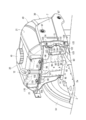
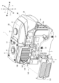
- FIG. 1 is a perspective view of a first embodiment of a horizontal engine configured in accordance with the present invention. It is a perspective view for demonstrating the attachment structure which attaches the protection member (side cover, screen) of the horizontal engine shown in FIG. It is the perspective view which removed the radiator and looked from the diagonally right rear in order to demonstrate the state which attaches the side cover of the horizontal type
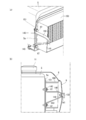
- FIG. 6 is a partial perspective view of the horizontal engine as viewed from the rear right side, for explaining how the screen is attached to the radiator. It is a perspective view for describing a 2nd embodiment of an attachment structure which attaches a screen to a horizontal engine of the present invention. It is the schematic explaining the 4th stay of 2nd Embodiment shown in FIG. 5, and the structure of a duct.
- the engine 1 shown in FIGS. 1 and 2 is a single-cylinder water-cooled horizontal diesel engine (hereinafter referred to as “horizontal engine”).
- horizontal engine a single-cylinder water-cooled horizontal diesel engine
- the longitudinal direction of the engine shown by arrow X in FIG. 1 is the front and back direction
- the width direction of the engine shown by arrow Y is the left and right direction
- the height direction of the engine shown by arrow Z is the vertical direction.
- the horizontal engine 1 includes an engine main body 4 in which a cylinder head 3 is disposed at the rear of the cylinder block 2.
- a fuel tank 20 for supplying fuel to the horizontal engine 1 is disposed on the front upper portion of the cylinder block 2.
- the upper portion of the fuel tank 20 is constituted by a tank cover 21.
- a radiator 5 whose upper surface is covered by a radiator cover 8 is disposed on the upper surface of the cylinder block 2 on the rear side of the fuel tank 20.
- the right side of the radiator cover 8 is partially cut away for convenience of description.
- Head lamps 30 are disposed on the front side of the fuel tank 20, and first protective members (side covers) 7 are disposed on the left and right sides of the fuel tank 20. Further, a top cover 40 is disposed between the front end of the tank cover 21 of the fuel tank 20 and the upper end of the headlamp 30 to cover the mounting structure on the front side of the fuel tank 20.
- the radiator 5 is disposed continuously at the rear end of the tank cover 21 of the fuel tank 20 and continuously at the rear end of the left and right side covers 7. And the left and right second protective members (screens) 9 in which the mesh-like vents 13 are formed.
- a fuel cap 10 is provided at the center of the upper surface of the fuel tank 20, and is disposed at the center of the tank cover 21.
- a radiator cap 11 is disposed at a central portion of the radiator cover 8, and a suspension bolt 12 for lifting the horizontal engine 1 at a center of gravity is provided in front of the radiator cap 11.
- a crankshaft (not shown) is rotatably disposed inside the cylinder block 2 in a posture along the left-right direction, and a flywheel 19 is attached to the left end of the crankshaft as shown in FIG. There is.
- the flywheel 19 is rotated at the time of start-up to facilitate engine start-up, and acts to suppress rotational fluctuation of the crankshaft after the horizontal engine 1 is started.
- FIG. 3 is a view of the fuel tank 20 as viewed obliquely from the right rear, and is a view in which the radiator 5, the radiator cover 8, the screen 9 and the like are omitted for the sake of convenience.
- a lamp bracket 50 formed of aluminum die-casting for attaching the headlamp 30, the top cover 40, and the left and right side covers 7 is disposed (see FIG. Only the attaching part 50a which fixes the front-end
- the lamp bracket 50 is disposed and fixed at a front upper corner of the cylinder block 2 (not shown).
- the upper surface and the front side surface of the cylinder block 2 are formed as surfaces with high processing accuracy, and secure high mounting accuracy of the lamp bracket 50 fixed to the upper end corner portion of the cylinder block 2.
- the fuel tank bracket 90 has a plate-like base 92 fixed to the upper surface 2 a of the cylinder block 2 with a plurality of bolts 91 (only a part of which is shown) and plate-like legs extending upward from the plate-like base 92
- a tank mounting plate portion 94 having a horizontal mounting support surface for mounting and supporting the flange portion 23 of the fuel tank 20 at the upper end position of the plate 93 and the right side of the plate leg 93; It integrally forms with the plate-shaped protection member attachment plate part 95 extended to.
- a thick first attachment portion 96 for fixing the flange 23 of the fuel tank 20 is formed on both side portions in the left-right direction of the tank attachment plate portion 94, and a tank attachment plate corresponding to a substantially central position in the width direction of the horizontal engine 1
- a second attachment portion 97 for attaching the suspension bolt 12 is formed at the center in the left-right direction of the portion 94.
- the flange 23 of the fuel tank 20 is mounted on the mounting support surface of the tank mounting plate portion 94 via the plate-shaped vibration isolation rubber 100, and the radiator cover 8 is attached to the upper surface of the flange 23 of the fuel tank 20.
- the bracket 110 is mounted via the anti-vibration rubber 101. In this mounting state, the flange 23 of the fuel tank 20 and the bracket 110 are fastened together with a bolt 102 from above with respect to the first mounting portion 96 of the tank mounting plate portion 94. By fixing in this manner, the rear side of the fuel tank 20 can be attached with little vibration.
- the first stay 120 is fixed by a bolt 123.
- the first stay 120 includes a metal stay main body 121 which is formed in a substantially U shape and opened in the front-rear direction and opened rightward.
- Attachment pieces 122 for fixing the upper and lower end portions of the cover connecting portion 71 of the side cover 7 are bent upward at the both end portions of the upper and lower ends.
- a bolt 124 is erected on the mounting piece 122 by welding so as to protrude outward.
- a substantially V-shaped second stay 130 formed to attach the front end portion of the screen 9 is provided to the attachment piece 122 of the first stay 120.
- an opening 131 having a diameter through which the bolt 124 erected on the mounting piece 122 can pass is formed at both end portions in the vertical direction, and the front end portion of the screen 9 is substantially central in the vertical direction.
- a mounting portion 132 is formed for mounting the As shown in FIG. 3, the mounting portion 132 is welded with a nut 134 which is screwed with a knob bolt 133 used when fixing the screen 9 to the back surface side.
- the mounting portion 132 is disposed so as to be biased rearward with respect to a straight line connecting bolts 124 formed on the upper and lower sides of the first stay 120.
- the bolt 124 penetrates and holds the openings 72 formed at the top and bottom of the cover connecting portion 71 of the side cover 7, and the tip of the side cover 7 is
- the lamp bracket 50 is fixed to the mounting portion 50 a of the lamp bracket 50 using a bolt 87.
- the cover connecting portion 71 is fixed to the first stay 120 via the second stay 130 by the nut 125 screwed to the bolt 124.
- the side cover 7 is fixed to the lamp bracket 50 at the front end side and is fixed to the fuel tank bracket 90 at the rear end side and positioned.
- a concave portion 72 opened rearward is formed at the center in the vertical direction of the cover connecting portion 71, and the mounting portion 132 of the second stay 130 is exposed from the concave portion 73.
- the screen 9 is attached to the horizontal engine 1 via a second stay 130 and a third stay 140 fixed to the radiator 5 adjacent to the rear of the duct 150.
- FIG. 4A shows the right side of the horizontal engine 1 as viewed from the rear in the front-rear direction, and the radiator cover 8 and the screen 9 are vertically positioned at the side position of the third stay 140 for convenience of explanation. It is shown in the cross section cut in the direction.
- the third stay 140 is formed by bending a cold-rolled steel plate (SPCC) having a thickness of about 3 mm, and has a substantially triangular shape having a top on the right side.
- SPCC cold-rolled steel plate
- An opening is formed in the attachment portion 141 formed at the top of the third stay 140, and a bolt 133 with a knob of the screen 9 described later is screwed to the back surface side of the attachment portion 141 as shown in FIG.
- a mated nut 142 is welded.
- mounting pieces 143 bent for attachment to the radiator 5 are formed at upper and lower end portions of the third stay 140, and openings (not shown) through which the bolts 87 pass through the mounting pieces 143. ) Is formed.
- a cover plate 5a having an opening at the center is disposed so that the cooling air passes through the cooling passage of the radiator 5.
- the third stay 140 is fixed by a bolt 87 at a position adjacent to the rear side of the duct 150 of the cover plate 5 a via the flange 151 of the duct 150.
- the front end side of the screen 9 is superimposed on the cover connecting portion 71 of the side cover 7 and the second stay 130, the second stay 130, It fixes to the attachment part 132,141 of the stay 140 of three.
- the side cover 7 is fixed to the fuel tank bracket 90 that fixes the fuel tank 20 to the upper surface of the engine body 4 via the first stay 120.
- the fuel tank bracket 90 secures strength for supporting the fuel tank 20 which is a heavy load, and is fixed in a state of high mounting strength as compared with the case where the side cover 7 is fixed to the flange 23 of the fuel tank 20 or the like. Mounting accuracy is high and there is no loss in appearance.
- the screen 9 is fixed to the second stay 130 attached to the fuel tank bracket 90 via the first stay 120 at the front end side and thicker than the duct 150 attached to the radiator 5 at the rear end side.
- the third stay 140 is to be fixed.
- the duct 150 for introducing cooling air to the radiator 5 is made of a thin steel plate of about 1 mm, and the strength of the duct 150 itself is low.
- the screen 9 is attached to the duct 150, the attachment strength and attachment accuracy of the screen 9 are ensured. Is difficult.
- the screen 9 is fixed to the fuel tank bracket 90 by the second stay 130 and to the radiator 5 by the third stay 140. Thereby, the attachment strength and the attachment accuracy of the screen 9 can be secured.
- the present invention is not limited to the above-described first embodiment, and various modifications can be envisioned as long as they fall within the technical scope of the present invention.
- the second embodiment will be described below with reference to FIGS. 5 and 6.
- the second embodiment is different from the first embodiment in the attachment structure on the rear end side of the screen 9, and the other structure is the same as that of the first embodiment. Therefore, the attachment structure on the rear end side of the screen 9 will be described, and the description of the other configuration will be omitted.
- the third stay 140 is configured separately from the duct 150, and the screen 9 is attached to the radiator 5 via the third stay 140.
- the fourth stay 145 is formed in a rectangular plate shape, and the fourth stay 145 constitutes one side of the rear side of the duct 155.
- the fourth stay 145 is formed of, for example, a rectangular plate material of SPCC with a thickness of 3 mm, and the rear side of the screen 9 is fixed by a bolt 133 with a knob.
- the mounting portion 146 is formed by bending. In the mounting portion 146, an opening through which the knob bolt 133 passes and a nut with which the knob bolt 133 is screwed are fixed by welding.
- the duct 155 is constituted by the fourth stay 145 and a U-shaped frame 156 which constitutes the other three side surfaces.
- the frame 156 is formed by bending a thin SPCC plate having a thickness of 1 mm, and includes a side surface 156a which is an upper side in a mounted state to the radiator 5, a side surface 156b which is a front side, and a side surface 156c which is a lower side.
- a mounting piece 158 bent to weld the fourth stay 145 is formed.
- a flange 157 for attaching the duct 155 to the radiator 5 is formed on the side surface 156b, and an opening 157a through which a mounting bolt (not shown) passes is formed.
- a flange 147 for attaching the duct 155 to the radiator 5 is also formed in the fourth stay 145, and an opening 147a for allowing a mounting bolt (not shown) to pass therethrough is formed in the flange 147.
- a step portion 159 with which the horizontal direction end of the flange 147 engages is formed at the corner of the side surface 156a and the side surface 156c.
- the duct 155 is formed by welding the fourth stay 145 to the bent portion 158 of the frame 156.
- Each x mark shown to a figure has shown the location to weld.
- a reinforcing member for connecting the central portion of the fourth stay 145 and the substantially central portion of the side surface 156a and the side surface 156c that constitute the frame 156. 160 is provided.
- the thickness of the connecting member 160 is thinner than the thickness (for example, 3 mm) of the fourth stay 145 and thicker than the thickness (for example, 1 mm) of the frame 156 (for example, 1.6 mm).
- the duct 155 configured as described above is attached to the radiator 5 as shown in FIG. 5, and the front end side of the screen 9 is attached to the second stay 130 by the knob bolt 133 as in the first embodiment. Further, the rear end side of the screen 9 is fixed to the mounting portion 146 of the fourth stay 145 by a bolt 133 with a knob. Thereby, the same operation and effect as those of the first embodiment described above can be obtained.
- the front end side of the screen 9 is fixed to the fuel tank bracket 90 via the second stay 130 and the rear end side of the screen 9 is via the third stay 140 or the fourth stay 145.
- the mounting strength and the mounting accuracy can be improved not only by fixing to the radiator 5 but also by adopting only the mounting structure on either the front end side or the rear end side.
Landscapes
- Engineering & Computer Science (AREA)
- Chemical & Material Sciences (AREA)
- Combustion & Propulsion (AREA)
- Mechanical Engineering (AREA)
- General Engineering & Computer Science (AREA)
- Cooling, Air Intake And Gas Exhaust, And Fuel Tank Arrangements In Propulsion Units (AREA)
Abstract
エンジン本体(4)の上部に配設される構成部品を側方から覆う保護部材の取付構造であって、エンジン本体(4)の上面に燃料タンク(20)を備え、エンジン本体(4)の上面に燃料タンク(20)を固定する燃料タンクブラケット(90)が取付けられ、燃料タンクブラケット(90)には、燃料タンク(20)の側面を覆う第一の保護部材(サイドカバー(7))を取り付けるための第一のステー(120)が取付けられ、第一の保護部材(サイドカバー(7))は、第一のステー(120)を介して、燃料タンクブラケット(90)に取り付けられるように構成されていることにより、取り付け強度及び取付精度が確保される。
Description
本発明は、エンジン本体の上面に燃料タンクが配設され、前記燃料タンク側面を覆う保護部材が配設されているエンジンの保護部材取付構造に関する。
従来から、エンジンの小型化、利便性を考慮して、エンジンの上面に燃料を貯留する燃料タンク、エンジンの冷却水を冷却するラジエータ等を隣接して配設する構成が知られている。具体的には、例えば、シリンダヘッド、シリンダブロック、及びクランクケースにより構成されるエンジン本体を横方向に配設する横型の水冷ディーゼルエンジンが知られており(例えば、特許文献1を参照。)、エンジン本体の上面の前方に燃料タンクを配設し、この燃料タンクに隣接した後方側にエンジンの冷却水を冷却するラジエータが配設される。このような小型のエンジンはコンパクトで使い勝手が良いことから、種々の用途に使用されている。
上記したような小型のエンジンでは、様々な状況において使用されることが想定され、エンジン本体の上面に配設される燃料タンクやラジエータを側方から保護する保護部材を配設する場合がある(例えば、特許文献2を参照。)。近年では、このような保護部材を配設する際に、意匠性、外観性を向上させることも考慮されるようになってきている。
上記した小型のエンジンにおいては、エンジン本体の上面に、大型の部品である燃料タンク、及びラジエータ等が配設されることから、エンジン本体上部におけるスペースが限られており、側方を覆う保護部材を配置する際には、例えば、燃料タンクの側面に形成されるフランジ面に溶接したステー等を介して固定することになる。しかし、燃料タンクは薄い板金製の鋼板により構成されていることから、フランジの強度も比較的弱く、取り付け精度も低いという問題がある。
また、ラジエータの側方には冷却用の空気を冷却水通路が配設される空間に導入する大型のダクトが配置されている。前記ダクトを覆い、通風機能を有する保護部材(スクリーン)を側方に取り付ける場合は、このダクトに直接保護部材を取り付けることになる。このダクトは、空気を導くためのものであることから、薄い鋼板で形成されている。よって、ダクトに保護部材を取り付ける場合も、上記した燃料タンクに保護部材を取り付ける場合と同様に、取り付け強度を確保することが困難である。さらに、燃料タンク、及びラジエータそれぞれに保護部材を取り付けるにしても、エンジン等から発せられる熱による各部品の歪により取り付け精度を確保することが困難になるという問題もある。
本発明は、上記事実に鑑みなされたものであり、その主たる技術課題は、エンジン本体の上部に配設される構成部品を側方から覆う保護部材の取付構造において、取り付け強度及び取付精度を確保した保護部材の取付構造を提供することにある。
上記主たる技術課題を解決するため、本発明によれば、エンジン本体の上面に燃料タンクと、前記燃料タンクを固定する燃料タンクブラケットとを備え、前記燃料タンクブラケットには、前記燃料タンクの側面を覆う第一の保護部材を取り付けるための第一のステーが取付けられ、前記第一の保護部材は、前記第一のステーを介して、前記燃料タンクブラケットに取り付けられる、保護部材取付構造が提供される。
前記エンジン本体の上面には、燃料タンクの後方に隣接してラジエータが備えられ、前記第一のステーには、前記ラジエータの側面を覆う第二の保護部材を取り付けるための第二のステーが取付けられ、前記第二の保護部材は、前記第二のステーを介して、前記燃料タンクブラケットに取り付けられるように構成することができる。
前記エンジン本体の上面には、燃料タンクの後方に隣接してラジエータが備えられ、前記ラジエータには、前記第一の保護部材と隣接して配設され前記ラジエータの側面を覆う第二の保護部材を取り付けるための第三のステーが取付けられ、該第二の保護部材は、前記第三のステーを介して、前記ラジエータに取り付けることができる。
前記エンジン本体の上面には、燃料タンクの後方に隣接してラジエータが備えられ、前記ラジエータには、前記第一の保護部材と隣接して配設され前記ラジエータの側面を覆う第二の保護部材を取り付けるための第四のステーが取付けられ、前記第四のステーは、前記ラジエータの側方に配設されるダクトの一側面を構成し、該第二の保護部材は、前記第四のステーを介して、前記ラジエータに取り付けられるようにしてもよい。
前記ダクトの一側面を構成する第四のステーは、ダクトを構成する他の側面よりも大きな厚みで構成されることが好ましい。
本発明の保護部材取付構造は、エンジン本体の上面に燃料タンクと、前記燃料タンクを固定する燃料タンクブラケットとを備える。前記燃料タンクブラケットには、前記燃料タンクの側面を覆う第一の保護部材を取り付けるための第一のステーが取付けられ、前記第一の保護部材は、前記第一のステーを介して、前記燃料タンクブラケットに取り付けられるように構成される。このことから、取付強度を確保することができる。また、エンジン本体からの熱による歪の影響を受けにくく、保護部材の取付位置精度を維持し、外観性を損なうことがない。さらに、燃料タンクブラケットに取り付けられた第二のステーにより第二の保護部材が取り付けられることにより、第二の保護部材の取付強度、及び取付精度を確保することができる。また、ラジエータに取り付けられた第三のステー、及び第四のステーの少なくともいずれかにより第二の保護部材が取り付けられることにより、第二の保護部材の取付強度、及び取付精度を確保することができる。
以下、本発明に基づいて構成された保護部材の取付構造の第1実施形態について添付図面を参照して説明する。
図1及び2に示すエンジン1は、単気筒の水冷式横型ディーゼルエンジン(以下「横型エンジン」と称する。)である。この横型エンジンの説明にあたっては、図1の矢印Xで示すエンジンの長手方向を前後方向とし、矢印Yで示すエンジンの幅方向を左右方向とし、矢印Zで示すエンジンの高さ方向を上下方向とする。
横型エンジン1は、図1及び2に示すように、シリンダブロック2の後方にシリンダヘッド3を配設したエンジン本体4を備えている。シリンダブロック2の前方上部には、横型エンジン1に燃料を供給する燃料タンク20が配設される。この燃料タンク20は、上部をタンクカバー21によって構成されている。図2に示すように、燃料タンク20の後方側のシリンダブロック2の上面には、上面がラジエータカバー8に覆われたラジエータ5が配設されている。なお、図2では、説明の都合上、ラジエータカバー8の右方側を一部切欠いた状態で示している。
燃料タンク20の前部側にはヘッドランプ30が配設され、燃料タンク20の左右両側には、第一の保護部材(サイドカバー)7が配設されている。また、燃料タンク20のタンクカバー21の前端とヘッドランプ30の上端との間には、燃料タンク20の前部側の取付構造を覆うトップカバー40が配設される。
ラジエータ5は、図2に示すように、燃料タンク20のタンクカバー21の後端に連続して上部に配設されたラジエータカバー8と、左右のサイドカバー7の後端に連続して配設されメッシュ状の通気口13が形成された左右の第二の保護部材(スクリーン)9とにより覆われる構成をなしている。
燃料タンク20の上面中央には燃料キャップ10が設けられており、タンクカバー21の中央に配設されている。ラジエータカバー8の中央部には、ラジエータキャップ11が配設され、ラジエータキャップ11の前方には、重心位置でこの横型エンジン1を吊上げるための吊りボルト12が突設される。
エンジン本体4の後方には、横型エンジン1のシリンダヘッド3内に形成された燃焼室(図示は省略する。)に吸気を供給するエアクリーナ15及び前記燃焼室から排出される排気を外部に放出するマフラ16が左右に配置されている。なお、図2ではこのエアクリーナ15、及びマフラ16は省略している。
シリンダブロック2の内部には図示しないクランク軸が左右方向に沿う姿勢で回転自在に配設されており、このクランク軸の左方端部には、図3に示すとおりフライホイール19が取付けられている。フライホイール19は、始動時に回転させられてエンジン始動を容易にすると共に、横型エンジン1が始動した後は、クランク軸の回転変動を抑制するように作用する。
図2、3を参照しながら、本発明に基づいて構成される保護部材(第一の保護部材(サイドカバー7)、第二の保護部材(スクリーン9))の横型エンジン1に対する取付構造について説明する。なお、図3は、燃料タンク20の右斜め後方から見た図であり、説明の都合上、ラジエータ5、ラジエータカバー8、及びスクリーン9等を省略した図を示している。
図2に示すように、燃料タンク20の前部には、ヘッドランプ30、トップカバー40、左右のサイドカバー7を取り付けるためのアルミダイキャストで形成されたランプブラケット50が配設されている(図ではランプブラケット50の一部であるサイドカバー7の先端部を固定する取り付け部50aのみが見えている。)。このランプブラケット50は、シリンダブロック2の前方上端角部に配置されて固定される(図示は省略する。)。シリンダブロック2の上面、及び前側側面は、加工精度の高い面として形成されており、シリンダブロック2の上端角部に固定されるランプブラケット50の高い取付精度を確保するものとなっている。
図3に示すように、エンジン本体4のシリンダブロック2の上面2aで、燃料タンク20の直後、すなわち、燃料タンク20とラジエータ5の間の位置には、左右方向に延び、略板状をなすアルミダイキャスト製の燃料タンクブラケット90が取付けられている。この燃料タンクブラケット90は、シリンダブロック2の上面2aに複数のボルト91(図では一部のみ示す。)で固定される板状基部92と、板状基部92から上方に延出される板状脚部93と、板状脚部93の上端位置において燃料タンク20のフランジ部23を載置支持する水平な載置支持面を備えたタンク取付板部94と、板状脚部93の右側側方に延出される板状の保護部材取付板部95とを一体形成したものである。
タンク取付板部94の左右方向両側部には、燃料タンク20のフランジ23を固定する厚肉の第1取付部96が形成され、横型エンジン1の幅方向の略中心位置に相当するタンク取付板部94の左右方向中央部には、吊りボルト12を取り付けるための第2取付部97が形成されている。
タンク取付板部94の載置支持面には、板状の防振ゴム100を介して燃料タンク20のフランジ23が載置され、さらに燃料タンク20のフランジ23の上面にラジエータカバー8を取り付けるためのブラケット110が防振ゴム101を介して載置される。この載置状態において、燃料タンク20のフランジ23とブラケット110とがタンク取付板部94の第1取付部96に対して上方からボルト102によって共締め固定される。このように固定することで、燃料タンク20の後部側を振動の少ない状態で取り付けることができる。
燃料タンクブラケット90の保護部材取付板部95の右端側の上下両端部には、厚肉のステー取付部98が形成され、両ステー取付部98には、サイドカバー7、スクリーン9を取り付けるための第一のステー120がボルト123で固定されている。
第一のステー120は、図2及び図3から理解されるように、前後方向視において右方に開放された略コ字状に折り曲げ形成された金属製のステー本体121を備え、ステー本体121の両先端部には、サイドカバー7のカバー連結部71の上下両端部を固定するための取付片122が上方に折り曲げ形成されている。この取付片122には、外方向に向けて突出するようにボルト124が溶接により立設されている。
さらに、図2に示すように、第一のステー120の取付片122に対し、スクリーン9の前端部を取り付けるために形成された略く字状をなす第二のステー130が配設される。この第二のステー130は、上下方向両端部に、上記した取付片122に立設されたボルト124が貫通可能な径の開口131が形成され、上下方向の略中央部にスクリーン9の前端部を取り付けるための取付部132が形成されている。この取付部132は、図3に示すように裏面側にスクリーン9を固定する際に使用するノブ付ボルト133が螺合するナット134が溶接されている。取付部132は、第一のステー120の上下に形成されたボルト124を結ぶ直線に対して、後方側に偏倚して配設されている。
サイドカバー7を横型エンジン1に取り付ける際は、まず、上記ボルト124に対し、サイドカバー7のカバー連結部71の上下に形成された開口72を貫通させて保持し、サイドカバー7の先端部をランプブラケット50の取付部50aにボルト87を用いて固定する。そして、ボルト124に対して螺合するナット125によってカバー連結部71を第二のステー130を間に介して第一のステー120に対して固定する。このようにして、サイドカバー7は、先端側がランプブラケット50に固定されると共に、後端側を燃料タンクブラケット90に固定され位置決めされる。さらに、本実施形態では、サイドカバー7の中央上方部を燃料タンク20のフランジ23に配設されたステー25にボルト87で固定することで振動発生時のばたつきをさらに防止することができる。なお、カバー連結部71の上下方向中央には、後方に開放された凹部72が形成されており、第二のステー130の取付部132がこの凹部73から表出する。
次に、サイドカバー7の後方に連続して配設される第二の保護部材(スクリーン)9の取付構造について説明する。図2から理解されるように、スクリーン9は、第二のステー130と、ダクト150の後方に隣接してラジエータ5に固定される第三のステー140を介して横型エンジン1に取り付けられる。
図4(a)には、横型エンジン1の右側を前後方向視における後方から見た図を示し、説明の都合上、ラジエータカバー8、及びスクリーン9を第三のステー140の側方位置において縦方向に切った断面で示している。
第三のステー140は、3mm程度の厚みの冷間圧延鋼板(SPCC)を折り曲げ加工により形成され、右方に頂部を有する略三角形状をなしている。第三のステー140の頂部に形成された取付部141には開口が形成されると共に、図4(b)に示すように取付部141の裏面側に後述するスクリーン9のノブ付ボルト133が螺合されるナット142が溶接されている。また、第三のステー140の上下両端部には、ラジエータ5に取り付けるために折り曲げられた取付片143が形成され、各取付片143には、ボルト87が貫通する開口部(図示は省略する。)が形成されている。
図4(b)に示すように、ラジエータ5の右方側の側面には、ラジエータ5の冷却通路を冷却風が通過するように中央部に開口が設けられたカバー板5aが配設され、第三のステー140は、カバー板5aのダクト150の後方側に隣接した位置にダクト150のフランジ151を間に介してボルト87により固定される。
スクリーン9を取り付ける際は、図2に示すように、スクリーン9の前端側を、サイドカバー7のカバー連結部71に重ね合せ、スクリーン9の前後のノブ付ボルト133により第二のステー130、第三のステー140の取付部132、141に固定する。
上述したように、サイドカバー7は、第一のステー120を介してエンジン本体4の上面に燃料タンク20を固定する燃料タンクブラケット90に固定される。燃料タンクブラケット90は、重量物である燃料タンク20を支持するための強度が確保されており、サイドカバー7を燃料タンク20のフランジ23等に固定する場合に比べ、取付強度が高い状態で固定することができ、取付精度も高く、外観性を損なうこともない。また、スクリーン9の固定は前端側を、燃料タンクブラケット90に第一のステー120を介して取り付けられた第二のステー130に、後端側を、ラジエータ5に取り付けたダクト150よりも厚肉の第三のステー140を介して固定するようにしている。ラジエータ5に冷却風を導入するダクト150は1mm程度の薄い鋼板で構成され、ダクト150自体の強度が低く、ダクト150にスクリーン9を取り付けると、スクリーン9の取付強度、及び取付精度を確保することが困難である。これに対し、本実施形態では、スクリーン9を第二のステー130により燃料タンクブラケット90に、第三のステー140によりラジエータ5に固定するようになっている。これにより、スクリーン9の取付強度と取付精度を確保することができる。
本発明は、上記した第1実施形態に限定されず、本発明の技術的範囲に含まれるかぎり、種々の変形例を想定することができる。以下に、図5、6を参照しながら、第2実施形態について説明する。
第2実施形態は、第1実施形態に対して、スクリーン9の後端側の取付構造が異なっており、それ以外の構造については第1実施形態と同一である。よって、スクリーン9の後端側の取付構造について説明し、それ以外の構成についての説明は省略する。
第1実施形態では、第三のステー140をダクト150とは別体で構成し、第三のステー140を介してスクリーン9をラジエータ5に取り付けていた。これに代えて、この第2実施形態では、第四のステー145を矩形の板状に形成し、さらに、第四のステー145によりダクト155の後方側の一側面を構成することとした。具体的には、図5、図6に示すように、第四のステー145を、例えば3mm厚のSPCCで矩形状の板材で形成し、スクリーン9の後方側をノブ付ボルト133によって固定するための取付部146が折り曲げ加工により形成されている。取付部146には、ノブ付ボルト133が貫通する開口とその裏面側にノブ付ボルト133が螺合するナットが溶接され固定されている。ダクト155は、この第四のステー145と、他の3つの側面を構成するコ字状の枠体156により構成される。この枠体156は、1mm厚の薄いSPCCの板材を折り曲げ、ラジエータ5に対する取付状態で上側となる側面156a、前側となる側面156b、下側となる側面156cからなり、コ字状の枠体156の開放両側端部には、第四のステー145を溶接するために折り曲げられた取付片158を形成している。側面156bには、ラジエータ5にダクト155を取り付けるためのフランジ157が形成され、取付ボルト(図示は省略)が貫通する開口157aが形成されている。また、第四のステー145にもダクト155をラジエータ5に取り付けるためのフランジ147が形成され、フランジ147には取付ボルト(図示は省略する。)を貫通させるための開口147aが形成されている。図に示すように、側面156a、側面156cの角部には、フランジ147の水平方向端部が係合する段差部159が形成されている。
図に示すように、ダクト155は、枠体156の折り曲げ部158に対し、第四のステー145を溶接することにより形成される。図に示す各×印は溶接する箇所を示している。なお、本実施形態では、さらにダクト155の強度を確保するために、第四のステー145の中央部と、枠体156を構成する側面156a、側面156cの略中央部を連結するための補強部材160を配設している。連結部材160の厚みは、第四のステー145の厚み(例えば3mm)よりも薄く、枠体156の厚み(例えば1mm)よりも厚く形成される(例えば、1.6mm)。これにより、第四のステー145の取付強度及び精度を確保しながら、ダクト155の重量増を必要以上に招くことがなく、さらに、タクト155全体の強度が確保される。
上記したように構成したダクト155を、図5に示すようにラジエータ5に取り付け、第1実施形態と同様にスクリーン9の前端側をノブ付ボルト133により第二のステー130に取り付ける。さらに、スクリーン9の後端側をノブ付ボルト133により第四のステー145の取付部146に固定する。これにより、上記した第1実施形態と同様の作用効果を得ることができる。
なお、本発明は、スクリーン9の前端側を第二のステー130を介して燃料タンクブラケット90に固定すると共にスクリーン9の後端側を第三のステー140、又は第四のステー145を介してラジエータ5に固定することに限定されず、上記した前端側、後端側のいずれか一方の取付構造のみを採用することによっても、取付強度、取付精度の向上を図ることができる。
1:横型エンジン
2:シリンダブロック
3:シリンダヘッド
4:エンジン本体
5:ラジエータ
7:第一の保護部材(サイドカバー)
8:ラジエータカバー
9:第二の保護部材(スクリーン)
10:燃料キャップ
11:ラジエータキャップ
12:吊りボルト
13:通気口
15:エアクリーナ
16:マフラ
19:フライホイール
20:燃料タンク
21:タンクカバー
23:フランジ
30:ヘッドランプ
40:トップカバー
50:ランプブラケット
71:カバー連結部
90:燃料タンクブラケット
92:板状基部
93:板状脚部
94:タンク取付板部
95:保護部材取付板部
96:第1取付部
97:第2取付部
98:ステー取付部
120:第一のステー
130:第二のステー
133:ノブ付ボルト
140:第三のステー
145:第四のステー
150、155:ダクト
160:補強部材
2:シリンダブロック
3:シリンダヘッド
4:エンジン本体
5:ラジエータ
7:第一の保護部材(サイドカバー)
8:ラジエータカバー
9:第二の保護部材(スクリーン)
10:燃料キャップ
11:ラジエータキャップ
12:吊りボルト
13:通気口
15:エアクリーナ
16:マフラ
19:フライホイール
20:燃料タンク
21:タンクカバー
23:フランジ
30:ヘッドランプ
40:トップカバー
50:ランプブラケット
71:カバー連結部
90:燃料タンクブラケット
92:板状基部
93:板状脚部
94:タンク取付板部
95:保護部材取付板部
96:第1取付部
97:第2取付部
98:ステー取付部
120:第一のステー
130:第二のステー
133:ノブ付ボルト
140:第三のステー
145:第四のステー
150、155:ダクト
160:補強部材
Claims (6)
- エンジン本体の上面に燃料タンクと、前記燃料タンクを固定する燃料タンクブラケットとを備え、
前記燃料タンクブラケットには、前記燃料タンクの側面を覆う第一の保護部材を取り付けるための第一のステーが取付けられ、
前記第一の保護部材は、前記第一のステーを介して、前記燃料タンクブラケットに取り付けられる、保護部材取付構造。 - 前記エンジン本体の上面には、燃料タンクの後方に隣接してラジエータが備えられ、
前記第一のステーには、前記ラジエータの側面を覆う第二の保護部材を取り付けるための第二のステーが取付けられ、
前記第二の保護部材は、前記第二のステーを介して、前記燃料タンクブラケットに取り付けられる、請求項1に記載の保護部材取付構造。 - 前記エンジン本体の上面には、燃料タンクの後方に隣接してラジエータが備えられ、
前記ラジエータには、前記第一の保護部材と隣接して配設され前記ラジエータの側面を覆う第二の保護部材を取り付けるための第三のステーが取付けられ、
該第二の保護部材は、前記第三のステーを介して、前記ラジエータに取り付けられる、請求項1に記載の保護部材取付構造。 - 前記エンジン本体の上面には、燃料タンクの後方に隣接してラジエータが備えられ、
前記ラジエータには、前記第一の保護部材と隣接して配設され前記ラジエータの側面を覆う第二の保護部材を取り付けるための第四のステーが取付けられ、
前記第四のステーは、前記ラジエータの側方に配設されるダクトの一側面を構成し、
該第二の保護部材は、前記第四のステーを介して、前記ラジエータに取り付けられる、請求項1に記載の保護部材取付構造。 - 前記ダクトの一側面を構成する第四のステーは、ダクトを構成する他の側面よりも大きな厚みで構成される請求項4に記載の保護部材取付構造。
- 前記第一のステーには、前記ラジエータの側面を覆う第二の保護部材を取り付けるための第二のステーが取付けられ、
前記第二の保護部材は、前記第二のステーを介して、前記燃料タンクブラケットに取り付けられる、請求項3乃至5のいずれかに記載の保護部材取付構造。
Applications Claiming Priority (2)
| Application Number | Priority Date | Filing Date | Title |
|---|---|---|---|
| JP2017164428A JP6766020B2 (ja) | 2017-08-29 | 2017-08-29 | 保護部材取付構造 |
| JP2017-164428 | 2017-08-29 |
Publications (1)
| Publication Number | Publication Date |
|---|---|
| WO2019044384A1 true WO2019044384A1 (ja) | 2019-03-07 |
Family
ID=65525318
Family Applications (1)
| Application Number | Title | Priority Date | Filing Date |
|---|---|---|---|
| PCT/JP2018/029261 Ceased WO2019044384A1 (ja) | 2017-08-29 | 2018-08-03 | 保護部材取付構造 |
Country Status (2)
| Country | Link |
|---|---|
| JP (1) | JP6766020B2 (ja) |
| WO (1) | WO2019044384A1 (ja) |
Citations (5)
| Publication number | Priority date | Publication date | Assignee | Title |
|---|---|---|---|---|
| JP2002347452A (ja) * | 2001-05-25 | 2002-12-04 | Kubota Corp | 燃料タンクのカバー装置 |
| JP2009006811A (ja) * | 2007-06-27 | 2009-01-15 | Kubota Corp | 歩行型作業機 |
| JP2013068100A (ja) * | 2011-09-20 | 2013-04-18 | Yanmar Co Ltd | エンジン |
| JP2013151913A (ja) * | 2012-01-25 | 2013-08-08 | Yanmar Co Ltd | エンジン |
| JP2017161053A (ja) * | 2016-03-11 | 2017-09-14 | ヤンマー株式会社 | エンジン |
-
2017
- 2017-08-29 JP JP2017164428A patent/JP6766020B2/ja active Active
-
2018
- 2018-08-03 WO PCT/JP2018/029261 patent/WO2019044384A1/ja not_active Ceased
Patent Citations (5)
| Publication number | Priority date | Publication date | Assignee | Title |
|---|---|---|---|---|
| JP2002347452A (ja) * | 2001-05-25 | 2002-12-04 | Kubota Corp | 燃料タンクのカバー装置 |
| JP2009006811A (ja) * | 2007-06-27 | 2009-01-15 | Kubota Corp | 歩行型作業機 |
| JP2013068100A (ja) * | 2011-09-20 | 2013-04-18 | Yanmar Co Ltd | エンジン |
| JP2013151913A (ja) * | 2012-01-25 | 2013-08-08 | Yanmar Co Ltd | エンジン |
| JP2017161053A (ja) * | 2016-03-11 | 2017-09-14 | ヤンマー株式会社 | エンジン |
Also Published As
| Publication number | Publication date |
|---|---|
| JP2019044583A (ja) | 2019-03-22 |
| JP6766020B2 (ja) | 2020-10-07 |
Similar Documents
| Publication | Publication Date | Title |
|---|---|---|
| JP4049684B2 (ja) | エンジンの燃料系保護装置 | |
| JP5603310B2 (ja) | エンジン作業機の位置規制装置 | |
| JP2019002357A (ja) | 内燃機関 | |
| JP2017008769A (ja) | エンジン燃料供給系部品の保護構造 | |
| JP7009268B2 (ja) | 作業車 | |
| JP5048297B2 (ja) | 自動二輪車 | |
| JPH11210457A (ja) | エンジンの排気管カバー取付構造 | |
| JP7013536B2 (ja) | エンジン | |
| JP6766020B2 (ja) | 保護部材取付構造 | |
| JPS5847568B2 (ja) | ベアリングビ−ム | |
| JP2009019348A (ja) | ホイ−ルロ−ダにおけるエンジン支持構造 | |
| JP2001182634A (ja) | エンジンの燃料タンク取付構造 | |
| JP5446647B2 (ja) | ハイブリッド建設機械のマフラー取付構造 | |
| JP4991159B2 (ja) | 自動二輪車の車体フレーム | |
| JP6655573B2 (ja) | エンジン | |
| US20160090891A1 (en) | Exhaust system of saddle-ride type vehicle | |
| JP2018158602A (ja) | 車両下部構造 | |
| JP7658936B2 (ja) | エンジン | |
| JP6718402B2 (ja) | エンジン | |
| JP2008025207A (ja) | ホイールローダの燃料タンク配設構造 | |
| JP2020060123A (ja) | エンジンの支持構造 | |
| JP2019011018A (ja) | エンジン支持構造 | |
| JP2715708B2 (ja) | エンジン補機の配設構造 | |
| JP7024474B2 (ja) | 自動二輪車のフレーム構造 | |
| JP4784134B2 (ja) | エンジンの支持構造 |
Legal Events
| Date | Code | Title | Description |
|---|---|---|---|
| 121 | Ep: the epo has been informed by wipo that ep was designated in this application |
Ref document number: 18852151 Country of ref document: EP Kind code of ref document: A1 |
|
| NENP | Non-entry into the national phase |
Ref country code: DE |
|
| 122 | Ep: pct application non-entry in european phase |
Ref document number: 18852151 Country of ref document: EP Kind code of ref document: A1 |