WO2019044330A1 - 紙送りロール - Google Patents
紙送りロール Download PDFInfo
- Publication number
- WO2019044330A1 WO2019044330A1 PCT/JP2018/028573 JP2018028573W WO2019044330A1 WO 2019044330 A1 WO2019044330 A1 WO 2019044330A1 JP 2018028573 W JP2018028573 W JP 2018028573W WO 2019044330 A1 WO2019044330 A1 WO 2019044330A1
- Authority
- WO
- WIPO (PCT)
- Prior art keywords
- convex portion
- paper feed
- feed roll
- groove
- paper
- Prior art date
- Legal status (The legal status is an assumption and is not a legal conclusion. Google has not performed a legal analysis and makes no representation as to the accuracy of the status listed.)
- Ceased
Links
Images

Classifications
-
- B—PERFORMING OPERATIONS; TRANSPORTING
- B65—CONVEYING; PACKING; STORING; HANDLING THIN OR FILAMENTARY MATERIAL
- B65H—HANDLING THIN OR FILAMENTARY MATERIAL, e.g. SHEETS, WEBS, CABLES
- B65H5/00—Feeding articles separated from piles; Feeding articles to machines
- B65H5/06—Feeding articles separated from piles; Feeding articles to machines by rollers or balls, e.g. between rollers
-
- B—PERFORMING OPERATIONS; TRANSPORTING
- B65—CONVEYING; PACKING; STORING; HANDLING THIN OR FILAMENTARY MATERIAL
- B65H—HANDLING THIN OR FILAMENTARY MATERIAL, e.g. SHEETS, WEBS, CABLES
- B65H3/00—Separating articles from piles
- B65H3/02—Separating articles from piles using friction forces between articles and separator
- B65H3/06—Rollers or like rotary separators
- B65H3/0638—Construction of the rollers or like rotary separators
-
- B—PERFORMING OPERATIONS; TRANSPORTING
- B65—CONVEYING; PACKING; STORING; HANDLING THIN OR FILAMENTARY MATERIAL
- B65H—HANDLING THIN OR FILAMENTARY MATERIAL, e.g. SHEETS, WEBS, CABLES
- B65H2404/00—Parts for transporting or guiding the handled material
- B65H2404/10—Rollers
- B65H2404/11—Details of cross-section or profile
- B65H2404/111—Details of cross-section or profile shape
- B65H2404/1118—Details of cross-section or profile shape with at least a relief portion on the periphery
-
- B—PERFORMING OPERATIONS; TRANSPORTING
- B65—CONVEYING; PACKING; STORING; HANDLING THIN OR FILAMENTARY MATERIAL
- B65H—HANDLING THIN OR FILAMENTARY MATERIAL, e.g. SHEETS, WEBS, CABLES
- B65H2404/00—Parts for transporting or guiding the handled material
- B65H2404/10—Rollers
- B65H2404/11—Details of cross-section or profile
- B65H2404/114—Built-up elements
Definitions
- the present invention relates to a paper feed roll suitably used in an electrophotographic apparatus such as a copying machine, a printer, a facsimile, etc. which employs an electrophotographic method.
- the paper feed roll is formed in a cylindrical shape, for example, by an elastic material such as a rubber cross-linked body, and its circumferential surface is a contact surface with the paper. Paper dust generated from paper may adhere to the circumferential surface of the paper feed roll. During repeated contact with the paper, paper dust may accumulate on the circumferential surface of the paper feed roll. When paper dust accumulates, the contact area of the circumferential surface with the paper decreases, and the friction coefficient of the contact surface with the paper decreases. As a result, conveyance failure of the sheet may occur.
- Patent Document 1 describes that a plurality of ridges and grooves are formed in parallel with the axial direction of the paper feed roll. Moreover, what formed the embossing in the surrounding surface of the paper feeding roll is described in patent document 2.
- the conventional paper feed rolls are not sufficient yet in that accumulation of paper dust is suppressed and a good coefficient of friction is maintained for a long time from the initial use.
- the sheets of paper used in recent years there are low-quality sheets, and low-quality sheets are prone to paper dust, and are likely to cause conveyance failure of sheets relatively early.
- the problem to be solved by the present invention is to provide a paper feed roll in which the conveyance failure of the paper due to the accumulation of paper dust is suppressed over a long period of time.
- a paper feed roll includes a shaft and an elastic layer formed on the outer periphery of the shaft, and the peripheral surface of the elastic layer is roughened by a protrusion.
- a protrusion is arranged in the direction different from the axial direction along the circumferential surface of the elastic layer, and a row of convex portions in a direction different from the axial direction and a convex portion parallel to the row between the rows is a groove of a continuous recess, and the width of the groove is larger than the distance between the protrusions in the row of the protrusions.
- the said convex part is a hemispherical convex part.
- the convex portions are preferably arranged in a direction different from the circumferential direction along the circumferential surface of the elastic layer.
- the convex portions are preferably arranged in a spiral along the circumferential surface of the elastic layer.
- the said convex part is arranged in the direction of an angle within ⁇ 10 degrees with respect to the circumferential direction along the circumferential surface of the said elastic-body layer.
- the said convex part may be arranged in the circumferential direction along the surrounding surface of the said elastic-body layer.
- the distance between projections in the row of projections is preferably in the range of 0 to 0.6 mm.
- the width of the groove is preferably in the range of 0.01 to 2.0 mm.
- the height of the projections is preferably in the range of 0.05 to 0.5 mm.
- the radius of curvature of the convex portion is preferably in the range of 0.05 to 1.0 mm.
- the pitch of the grooves is preferably in the range of 0.1 to 2.0 mm.
- the convex portion may be a ball base convex portion. It is preferable that the upper base of the ball-and-stand shaped convex part is a grinding surface.
- the upper base of the ball-and-pod shaped convex part may be a plane.
- the upper base of the spherical base may be a curved surface having a larger radius of curvature than the spherical zone of the spherical base.
- the ratio (r1 / r2) of the diameter r1 of the upper base to the diameter r2 of the lower base in the spherical base is preferably in the range of 0.50 to 0.95.
- the angle between the contact surface of the spherical zone of the spherical base and the upper base of the spherical base at the point of intersection with the upper base of the spherical base is within the range of 100 to 150 °. Is preferred. It is preferable that the height of the spherical base be in the range of 0.02 to 0.40 mm.
- the paper feed roll according to the present invention along the circumferential surface of the elastic layer, the row of the convex portions arranged in the direction different from the axial direction along the circumferential surface of the elastic layer and the row of the convex portions parallel thereto. Paper is formed over a long period of time because the groove of the concave portion continuous in the direction different from the axial direction is formed and the width of the groove is larger than the distance between the convex portions in the row of the convex portions arranged in the direction different from the axial direction Defective sheet conveyance due to powder accumulation is suppressed.
- the width of the groove is greater than the distance between the projections in the row of projections arranged in a direction different from the axial direction, so that paper dust generated at the projections that will be in contact with the paper during paper feeding is Paper dust is discharged from the groove to the outside of the roll without staying in the groove with rotation of the roll because the groove is easily released from the convex portion to the adjacent groove and the groove is continuous in the direction different from the axial direction. It is because it is easy to do.
- paper dust generated in the convex portions is a groove adjacent to the convex portions. It is easy to escape. Then, even in the case where the convex portions are arranged in the circumferential direction along the circumferential surface of the elastic layer, paper dust generated in the convex portions can easily escape from the convex portions to the adjacent groove.
- the height of the convex portion is in the range of 0.05 to 0.5 mm, the volume of the groove increases, paper dust moved to the groove is unlikely to be clogged with the groove, and the groove is easily discharged out of the roll.
- the size of the convex portion can be appropriately reduced, the moving distance of the paper dust to the groove can be shortened, and the paper dust can be easily discharged into the groove.
- the radius of curvature of the convex portion is in the range of 0.05 to 1.0 mm, the contact area with the sheet is increased, the load on the sheet is suppressed to a low level, and the generation of paper dust is easily suppressed.
- the size of the convex portion can be appropriately reduced, the moving distance of the paper dust to the groove can be shortened, and the paper dust can be easily discharged into the groove.
- the width of the groove increases, so the paper dust moved to the groove is unlikely to be clogged by the groove and is easily discharged from the groove to the outside of the roll.
- the size of the convex portion can be appropriately reduced, the moving distance of the paper dust to the groove can be shortened, and the paper dust can be easily discharged into the groove.
- the convex portion has a ball-and-hole shape
- generation of paper dust can be suppressed, and conveyance failure of the sheet can be suppressed for a long time.
- the upper bottom of the ball-and-stand shaped convex portion is a polished surface
- the generation of paper dust can be particularly suppressed.
- the ratio (r1 / r2) of the diameter r1 of the upper base to the diameter r2 of the lower base in the convex portion is in the range of 0.50 to 0.95, the generation of paper dust is particularly suppressed, and over a long period of time Defective sheet conveyance can be suppressed.
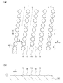
- FIG. 2 is an enlarged schematic view (a) of a circumferential surface of the paper feed roll shown in FIG. 1 and a cross-sectional view taken along the line AA (b).
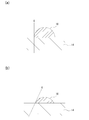
- FIG. 5 is an enlarged schematic cross-sectional view of a convex portion of a paper feed roll, in which the shape of a half of a sphere is cut at a plane passing through the center of the sphere (a); It is a figure showing the thing (b) of the shape smaller than half.
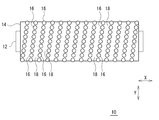
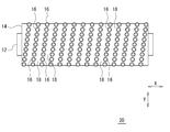
- FIG. 1 is a schematic external view of a paper feed roll according to an embodiment of the present invention.
- FIG. 2 is an enlarged schematic view (a) of the circumferential surface of the paper feed roll shown in FIG. 1 and a cross-sectional view along the line AA (b).
- the paper feed roll 10 includes a shaft 12 and an elastic layer 14 formed on the outer periphery of the shaft 12.
- the elastic layer 14 is a layer (the outermost layer) appearing on the surface of the paper feed roll 10.
- the elastic layer 14 is tubular (cylindrical).
- a hemispherical convex portion 16 is provided on the circumferential surface of the elastic layer 14.
- a space between the convex portion 16 and the convex portion 16 is a concave portion lower than the convex portion 16, and the convex portion 16 provides unevenness on the peripheral surface of the elastic layer 14.
- the spherical shape may be a substantially spherical shape as long as it has a curved surface and a shape close to a spherical shape.
- the spherical shape includes, for example, a true spherical shape and an elliptical spherical shape.
- a hemispherical shape is a shape of a half of a sphere cut in a plane passing through the center of the sphere, a shape cut in a plane not passing through the center of a sphere, a shape larger than half a sphere, or a half of a sphere Also includes small ones.
- the protrusions 16 are arranged in a direction different from the axial direction X along the circumferential surface of the elastic layer 14. Specifically, the convex portions 16 are arranged along the circumferential surface of the elastic layer 14 along the direction of the predetermined angle ⁇ with respect to the circumferential direction Y. The convex portions 16 are arranged in a spiral along the circumferential surface of the elastic layer 14. The convex portions 16 are also arranged in the axial direction X along the circumferential surface of the elastic layer 14, but the convex portions 16 may not be arranged in the axial direction X.
- the convex portions 16 and the convex portions 16 in the row are separated by a predetermined distance a. Between the row of the convex portions 16 in the direction different from the axial direction X and the row of the convex portions 16 parallel thereto, there is a continuous groove 18 of the concave portion.
- the width b of the groove 18 is larger than the protrusion separation distance a.
- the width b of the groove 18 is a separation distance in the axial direction X of the row of the convex portions 16 in a direction different from the axial direction X and the row of the convex portions 16 parallel thereto.
- the elastic layer 14 is formed by the row of the convex portions 16 arranged in the direction different from the axial direction X along the circumferential surface of the elastic layer 14 and the row of the convex portions 16 parallel thereto.
- the groove 18 of the concave portion continuous in the direction different from the axial direction X is formed along the circumferential surface of the groove, and the convex portions in the row of the convex portion 16 are arranged in the direction different from the axial direction X Since the distance is larger than the distance a, the conveyance failure of the sheet due to the accumulation of the paper dust can be suppressed for a long time.
- the width of the groove 18 is larger than the protrusion separation distance a in the row of the protrusions 16 arrayed in a direction different from the axial direction X, so that it occurs at the protrusions 16 which will be the contact surface with the paper during paper feeding. Paper dust is easily released from the convex portion 16 to the adjacent groove 18, and the groove 18 is continuous in a direction different from the axial direction X, so that the paper dust is moved to the groove 18 as the roll rotates. It is because it is easy to discharge from the groove 18 to the outside of the roll without staying.
- the continuous groove 18 of the concave portion is formed in the direction of the predetermined angle ⁇ with respect to the circumferential direction Y, so the paper dust generated in the convex portion 16 is adjacent to the convex portion 16
- the groove 18 makes it easy to escape.
- the convex portion 16 is hemispherical and the contact surface with the sheet is a curved surface, the generation of paper dust can be relatively suppressed and the sheet feeding performance is also excellent.
- the angle ⁇ is preferably within ⁇ 10 ° with respect to the circumferential direction Y. That is, it is preferable that the convex portions 16 be arranged along the circumferential surface of the elastic layer 14 in the direction of an angle within ⁇ 10 ° with respect to the circumferential direction Y.
- the groove 18 of the continuous concave portion is formed in the direction of the predetermined angle ⁇ with respect to the circumferential direction Y, the paper dust generated in the convex portion 16 is separated from the convex portion 16 by the groove 18 adjacent thereto. It is easy to escape.
- the angle ⁇ be an angle within ⁇ 10 ° with respect to the circumferential direction Y from the viewpoint that the paper powder is easily discharged from the groove 18 to the outside of the roll.
- the distance between projections a is preferably in the range of 0 to 0.6 mm.
- the protrusion separation distance a is 0.6 mm or less, paper dust does not easily stay in the gaps in the row of the convex portions 16, paper dust is easily moved to the adjacent groove 18, and paper dust is discharged into the groove 18. It's easy to do. Further, since the number of the convex portions 16 in the direction of the row of the convex portions 16 is increased, the contact area with the sheet is increased, the load on the sheet is suppressed small, and the generation of paper dust is easily suppressed. From this viewpoint, the protrusion separation distance a is more preferably 0.5 mm or less, and still more preferably 0.4 mm or less.
- the width b of the groove 18 is preferably in the range of 0.01 to 2.0 mm.
- the width b of the groove 18 is 0.01 mm or more, paper dust moved to the groove 18 is not easily clogged by the groove 18 and is easily discharged from the groove 18 to the outside of the roll.
- the width b of the groove 18 is more preferably 0.05 mm or more, and further preferably 0.1 mm or more.
- the width b of the groove 18 is 2.0 mm or less, the number of the convex portions 16 in the axial direction X increases, so the contact area with the paper increases, and the load on the paper is suppressed to a small amount. It is easy to suppress the generation of powder.
- the width b of the groove 18 is more preferably 1.8 mm or less, and further preferably 1.5 mm or less.
- the height h of the projection 16 is preferably in the range of 0.05 to 0.5 mm.
- the height h of the convex portion 16 is 0.05 mm or more, the volume of the groove 18 increases, paper dust moved to the groove 18 is not easily clogged by the groove 18, and the groove 18 easily discharges from the roll.
- the height h of the convex portion 16 is more preferably 0.1 mm or more.
- the size r ′ of the convex portion 16 is appropriately reduced to a small size, so the moving distance of the paper powder to the groove 18 is suppressed to a short length. Can be discharged into the groove 18 easily.
- the height h of the convex portion 16 is more preferably 0.3 mm or less.
- the curvature radius r of the convex portion 16 is preferably in the range of 0.05 to 1.0 mm.
- the radius of curvature of the convex portion 16 is 0.05 mm or more, the contact area with the sheet becomes large, the load on the sheet is suppressed small, and the generation of paper dust is easily suppressed.
- the curvature radius r of the convex portion 16 is more preferably 0.10 mm or more.
- the curvature radius r of the convex portion 16 is 1.0 mm or less, the size r ′ of the convex portion 16 is appropriately reduced to a small size, so the moving distance of paper dust to the groove 18 is suppressed to a short length. Can be discharged into the groove 18 easily.
- the curvature radius r of the convex portion 16 is more preferably 0.8 mm or less.
- the size r ′ of the protrusion 16 is represented by the maximum diameter of the protrusion 16.
- the size r ′ of the projection 16 is determined by the height h of the projection 16 and the radius of curvature r of the projection 16.
- the height h of the convex portion 16 and the curvature radius r of the convex portion 16 may be adjusted.
- the size r ′ of the convex portion 16 is preferably in the range of 0.10 to 1.73 mm.
- the size r ′ of the convex portion 16 is 0.10 mm or more, the contact area with the sheet becomes large, the load on the sheet is suppressed to a small level, and the generation of paper dust is easily suppressed. From this point of view, the size r ′ of the convex portion 16 is more preferably 0.20 mm or more. In addition, when the size r ′ of the convex portion 16 is 1.73 mm or less, the moving distance of the paper dust to the groove 18 can be shortened, and the paper dust can be easily discharged to the groove 18. From this viewpoint, the size r ′ of the convex portion 16 is more preferably 1.30 mm or less.
- the convex portion 16 is a half of a sphere cut at a plane passing through the center of the sphere. It becomes a thing of shape.
- the convex portion 16 has a shape smaller than half of the sphere.
- the paper dust is easily moved from the convex portion 16 to the groove 18 and the paper dust is easily discharged to the groove 18.
- h ⁇ (1/2) ⁇ r it is particularly preferable that h ⁇ (1/2) ⁇ r.
- the pitch p of the grooves 18 is determined by the size r ′ of the projections 16 (the radius of curvature r of the projections 16 and the height h of the projections 16) and the width b of the grooves 18.
- the pitch p of the grooves 18 may be appropriately determined by these.
- the pitch p of the grooves 18 is preferably in the range of 0.1 to 2.0 mm.
- the pitch p of the grooves 18 is more preferably 0.3 mm or more.
- the pitch p of the grooves 18 is 2.0 mm or less, the size r ′ of the convex portions 16 is appropriately reduced to a small distance, and hence the moving distance of the paper powder to the grooves 18 is suppressed to a short length.
- the pitch p of the grooves 18 is more preferably 1.8 mm or less.
- Arrangement angle ⁇ of the convex portions 16, distance a of the convex portions a, width b of the grooves 18, height h of the convex portions 16, curvature radius r of the convex portions 16, size r ′ of the convex portions 16 and pitch p of the grooves 18 Can be determined by analyzing a surface photograph and an axial cross-sectional photograph of the elastic layer 14.
- the paper feed roll according to the present invention is not limited to the above embodiment.
- the hemispherical projections 16 are arranged in a spiral along the circumferential surface of the elastic layer 14 in the direction of the predetermined angle ⁇ with respect to the circumferential direction Y, but not in a spiral
- a plurality of rows may be arranged along the circumferential surface of the elastic layer 14 in the direction of the predetermined angle ⁇ with respect to the circumferential direction Y.
- the convex portion 16 is hemispherical, but as long as it has a curved surface, it may have a shape in which the skirt is spread.
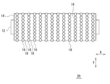
- the paper feed roll according to the present invention may be configured, for example, like the paper feed roll 20 shown in FIG.
- the paper feed roll 20 shown in FIG. 4 is different from the paper feed roll 10 shown in FIG. 1 in the arrangement of the convex portions 16. Except for this point, it is the same as the paper feed roll 10 shown in FIG. 1, and the description thereof will be omitted.
- the convex portions 16 are arranged in a direction different from the axial direction X along the circumferential surface of the elastic layer 14. Specifically, the protrusions 16 are arranged in the circumferential direction Y along the circumferential surface of the elastic layer 14. The convex portions 16 are also arranged in the axial direction X along the circumferential surface of the elastic layer 14, but the convex portions 16 may not be arranged in the axial direction X.
- the convex portions 16 and the convex portions 16 in the row are separated by a predetermined distance. Between the row of the convex portions 16 in the circumferential direction Y and the row of the convex portions 16 parallel to this, there is a continuous groove 18 of the concave portion.
- the width of the groove 18 is larger than the distance between the projections 16.
- the width of the groove 18 is the separation distance in the axial direction X of the row of the convex portions 16 in the circumferential direction Y and the row of the convex portions 16 parallel thereto.
- the circumferential surface of the elastic layer 14 is formed by the row of the convex portions 16 arranged in the circumferential direction Y along the circumferential surface of the elastic layer 14 and the row of the convex portions 16 parallel thereto. Since the groove 18 of the concave portion continuous in the circumferential direction Y is formed along the side wall, the width of the groove 18 is larger than the distance between the convex portions in the row of the convex portions 16 arranged in the circumferential direction Y It is possible to suppress paper conveyance failure due to accumulation of paper dust.
- the width of the groove 18 is larger than the distance between the projections in the row of the projections 16 arrayed in the circumferential direction Y, so that paper dust generated at the projections 16 which is a contact surface with the paper at the time of paper feeding Since it becomes easy to escape from the convex part 16 to the adjacent groove 18 and the groove 18 is continuous in the circumferential direction Y, paper dust does not stay in the groove 18 with the rotation of the roll, and from the groove 18 It is because it is easy to discharge out of the roll.
- the convex part separation distance a of the paper feed roll 10 shown in FIG. 1 the width b of the groove 18, the height h of the convex part 16, the curvature radius r of the convex part 16, the groove 18 Similar to the pitch p, the distance between the projections, the width of the grooves 18, the height of the projections 16, the radius of curvature of the projections 16, the pitch of the grooves 18, etc. may be set.
- FIG. 5 shows a paper feed roll according to another embodiment of the present invention.
- FIGS. 6 and 7 show an example of the cross-sectional shape of the ball-shaped convex portion.
- the paper feed roll 30 shown in FIG. 5 is different from the paper feed roll 10 shown in FIG. 1 in the shape of the convex portion 16. Except for this point, it is the same as the paper feed roll 10 shown in FIG. 1, and the description thereof will be omitted.
- the convex portion 16 is a spherical base convex portion.
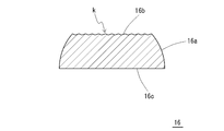
- the spherical surface intersects two parallel planes, the portion of the spherical surface sandwiched by these two planes is the spherical zone, and the spherical zone and the solid surrounded by these two planes are the spherical base. That is, the spherical base-like convex portion is the solid convex portion 16 surrounded by the spherical band 16a and the two planes (upper base 16b and lower base 16c).
- the upper bottom 16b is a surface that appears on the outside, and is a surface that comes in contact with the sheet.
- the lower base 16 c is a surface integrated with the circumferential surface of the elastic layer 14.
- the spherical surface is a spherical surface having a substantially spherical shape, and may be a spherical surface having a curved surface and a shape close to a spherical shape.
- the spherical shape includes, for example, a true spherical shape and an elliptical spherical shape.
- One of the two planes of the ball platform may be a plane passing through the center of the sphere, or both of the two planes of the ball platform may be planes not passing through the center of the sphere.
- the two flat surfaces of the ball pedestal may be surfaces close to a flat surface, and may be, for example, a curved surface having a radius of curvature larger than that of the spherical zone. That is, the upper base 16 b of the spherical base convex portion 16 may be a flat surface or a curved surface having a radius of curvature larger than that of the spherical zone. Further, as shown in FIG. 7, the upper bottom 16 b of the convex portion 16 may be a polishing surface k. The polishing surface k can be formed by polishing the upper bottom 16 b of the convex portion 16.
- the spherical band 16 a of the convex portion 16 is a curved surface convex upward, and the contact surface 1 of the spherical band 16 a of the convex portion 16 and the upper bottom 16 b of the convex portion 16 at the intersection 16 d with the upper bottom 16 b of the convex portion 16 Since the angle ⁇ with this is gentle at an obtuse angle, the paper surface is less likely to be caught on the shoulder portion s, which is the intersection of the upper bottom 16b of the convex portion 16 and the ball band 16a, thereby suppressing the generation of paper dust. is there.
- the convex portion 16 has the upper bottom 16b of a flat surface or a curved surface having a radius of curvature larger than that of the spherical band 16a, the contact area with the sheet at the tip of the convex portion 16 is increased, the stress is dispersed, and pressing against the sheet This is because the pressure is kept low and the amount of paper dust generated is thereby suppressed.
- the upper bottom 16 b of the convex portion 16 is the polishing surface k, generation of paper dust can be particularly suppressed.
- the diameter of the lower base 16 c be larger than that of the upper base 16 b of the ball-and-pod shaped convex part 16.
- the ratio (r1 / r2) of the diameter r1 of the upper base 16b to the diameter r2 of the lower base 16c is preferably in the range of 0.50 to 0.95.
- r1 / r2 is 0.50 or more, the area of the upper bottom 16b in contact with the sheet is increased, the stress is dispersed, the pressing force on the sheet is suppressed to a low level, and the generation amount of paper dust is easily suppressed.
- r1 / r2 is more preferably 0.55 or more, and further preferably 0.60 or more.
- r1 / r2 is 0.95 or less, the angle ⁇ between the contact surface 1 of the spherical band 16a and the upper base 16b at the intersection 16d of the spherical band 16a and the upper base 16b is large, and the spherical band 16a and the upper base Since the paper surface is less likely to be caught on the shoulder portion s where the portion 16b intersects, the amount of paper dust generated is likely to be reduced. From this viewpoint, r1 / r2 is more preferably 0.90 or less, and still more preferably 0.85 or less.
- the angle ⁇ between the contact surface 1 of the spherical band 16a of the convex portion 16 and the upper base 16b of the convex portion 16 at the intersection 16d with the upper bottom 16b of the convex portion 16 is preferably in the range of 100 to 150 °. .
- the angle ⁇ is 100 ° or more, the paper surface is less likely to be caught on the shoulder portion s where the upper bottom 16b of the convex portion 16 and the spherical band 16a intersect, so the amount of paper dust generated is easily suppressed.
- the angle ⁇ is more preferably 110 ° or more, and further preferably 120 ° or more.
- the angle ⁇ is 150 ° or less, the area of the upper bottom 16b in contact with the paper becomes large, the stress is dispersed, the pressing force on the paper is suppressed low, and the generation amount of paper dust is easily suppressed small.
- the formed angle ⁇ is more preferably 145 ° or less, further preferably 140 ° or less.
- the height h of the projection 16 is preferably in the range of 0.02 to 0.40 mm. If the height h of the convex portion 16 is 0.02 mm or more, the volume of the concave portion between the convex portion 16 and the convex portion 16 becomes large, and the generated paper dust is not easily clogged in the concave portion. From this viewpoint, the height h of the convex portion 16 is more preferably 0.05 mm or more.
- the height h of the convex portion 16 is 0.40 mm or less, the diameter r2 of the lower base 16c of the convex portion 16 can be appropriately reduced, so the dispersibility of the convex portion 16 is improved, and the pressure dispersion on the sheet Improves the effect of This makes it easy to suppress the generation of paper dust.
- the height h of the convex portion 16 is more preferably 0.30 mm or less.
- the diameter r1 of the upper bottom 16b of the projection 16 is preferably in the range of 0.095 to 0.50 mm.
- the diameter r1 of the upper bottom 16b is 0.095 mm or more, the area of the upper bottom 16b contacting the paper is large, the stress is dispersed, the pressing force on the paper is suppressed low, and the generation amount of paper dust is suppressed small.
- the diameter r1 of the upper bottom 16b is more preferably 0.10 mm or more, and still more preferably 0.15 mm or more.
- the diameter r1 of the upper bottom 16b is 0.50 mm or less
- the diameter r2 of the lower bottom 16c of the convex portion 16 is appropriately reduced, so that the dispersibility of the convex portion 16 is improved, and the pressure dispersion to the paper is achieved. The effect is improved. This makes it easy to suppress the generation of paper dust.
- the diameter r1 of the upper bottom 16b is more preferably 0.40 mm or less.
- the diameter r2 of the lower base 16c of the projection 16 is preferably in the range of 0.10 to 1.00 mm. If the diameter r2 of the lower base 16c is 0.10 mm or more, the area of the upper base 16b contacting the paper relatively increases, the stress is dispersed, and the pressing force on the paper is suppressed to a low level, and the amount of paper dust generated Is easy to be reduced. In this respect, the diameter r2 of the lower base 16c is more preferably 0.20 mm or more.
- the diameter r2 of the lower base 16c is 1.00 mm or less
- the diameter r2 of the lower base 16c of the convex portion 16 is appropriately reduced, so the dispersibility of the convex portion 16 is improved, and the pressure dispersion to the paper is performed. The effect is improved. This makes it easy to suppress the generation of paper dust.
- the diameter r2 of the lower base 16c is more preferably equal to or less than 0.80 mm, and still more preferably equal to or less than 0.60 mm.
- the radius of curvature SR of the spherical zone 16a is preferably in the range of 0.05 to 0.50 mm. If the radius of curvature SR is 0.05 mm or more, the curved surface of the spherical band 16a is relatively gentle, the area of the upper bottom 16b in contact with the paper tends to be large, the stress is dispersed, and the pressure on the paper is suppressed low. It is easy to reduce the amount of paper dust generated. From this viewpoint, the curvature radius SR is more preferably 0.10 mm or more.
- the radius of curvature SR is 0.50 mm or less, the diameter r2 of the lower base 16c of the convex portion 16 is appropriately reduced, so the dispersibility of the convex portion 16 is improved, and the pressure dispersion effect on the paper is improved. Do. This makes it easy to suppress the generation of paper dust. From this viewpoint, the radius of curvature SR is more preferably 0.40 mm or less.
- the convex portion 16 spirals in the direction of the predetermined angle ⁇ with respect to the circumferential direction Y along the circumferential surface of the elastic layer 14
- it may be arranged in a plurality of rows, not in a spiral but along a circumferential surface of the elastic layer 14 in the direction of a predetermined angle ⁇ with respect to the circumferential direction Y. .
- the convex portions 16 are arranged in a spiral along the circumferential surface of the elastic layer 14 in the direction of the predetermined angle ⁇ with respect to the circumferential direction Y.
- the convex portions 16 are arranged in the circumferential direction Y along the circumferential surface of the elastic layer 14. It may be The convex portions 16 are also arranged in the axial direction X along the circumferential surface of the elastic layer 14, but the convex portions 16 may not be arranged in the axial direction X.
- the convex portions 16 and the convex portions 16 in the row are separated by a predetermined distance. Between the row of the convex portions 16 in the circumferential direction Y and the row of the convex portions 16 parallel to this, there is a continuous groove 18 of the concave portion.
- the width of the groove 18 is larger than the distance between the projections 16.
- the width of the groove 18 is the separation distance in the axial direction X of the row of the convex portions 16 in the circumferential direction Y and the row of the convex portions 16 parallel thereto.
- the angle ⁇ of the paper feed roll in which the convex portion 16 is hemispherical, the convex portion separation distance a, the width b of the groove 18 and the pitch p of the groove 18 may be set.
- a core metal made of a solid metal body, a metal cylindrical body whose inside is hollowed out, or the like is used. And as the material, stainless steel, aluminum, what plated iron etc. are mentioned.
- an adhesive, a primer, etc. may be apply
- the elastic layer 14 is formed of an elastic material such as a crosslinked rubber.
- the material is not particularly limited as long as it is a rubber-like elastic material.
- known rubber materials such as urethane rubber, hydrin rubber and silicone rubber can be used.
- the elastic layer 14 is preferably conductive or semiconductive. Specifically, the volume resistivity of the elastic layer 14 is preferably in the range of 10 2 to 10 10 ⁇ ⁇ cm, 10 3 to 10 9 ⁇ ⁇ cm, and 10 4 to 10 8 ⁇ ⁇ cm. If the elastic layer 14 is conductive or semiconductive, surface residual charge on the elastic layer 14 can be suppressed to a low level, and adhesion of paper dust can be easily suppressed.
- the elastic layer 14 may contain a conductive agent from the viewpoint of reducing electrical resistance.
- the conductive agent include an electron conductive agent and an ion conductive agent.
- the electron conductive agent include carbon black, graphite, c-TiO 2 , c-ZnO, c-SnO 2 (c- represents conductivity) and the like.
- the ion conductive agent include quaternary ammonium salts, borates, surfactants and the like.
- Additives include lubricants, vulcanization accelerators, antioxidants, light stabilizers, viscosity modifiers, processing aids, flame retardants, plasticizers, fillers, dispersants, antifoams, pigments, mold release agents, etc. Can be mentioned.
- the thickness of the elastic layer 14 is not particularly limited, and may be appropriately set within the range of 0.1 to 10 mm.
- the elastic layer 14 can be formed by molding using a rubber composition and the like with a molding die. For example, after the shaft 12 is coaxially installed in the hollow portion of the roll molding die, and the uncrosslinked rubber composition is injected, heated and cured (crosslinked), the shaft 12 is removed or the like.
- the elastic layer 14 can be formed on the outer periphery of As the molding die, a mold having a concave portion having a shape corresponding to the convex portion 16 can be used on the inner peripheral surface thereof.
- the convex portion 16 of the elastic layer 14 can be formed, for example, by mold transfer using a molding die.
- Examples 1 to 18, Comparative Examples 1 to 4 An elastic layer (thickness 3 mm) of a urethane rubber composition was formed on the outer periphery of a core material ( ⁇ 6, made of SUS304) using a cylindrical molding die having a predetermined recessed portion on the inner peripheral surface. Thereby, a paper feed roll having a surface shape as shown in FIG. 4 or FIG. 1 was obtained. That is, asperities are provided on the circumferential surface of the elastic layer by hemispherical projections. In Example 1 and Comparative Example 1, as shown in FIG. 4, the hemispherical projections are arranged so as to circulate along the circumferential surface of the elastic layer. In the other examples and comparative examples, as shown in FIG.
- the hemispherical projections are arranged in a spiral along the circumferential surface of the elastic layer.
- the groove of the crevice continued along the peripheral surface of an elastic body layer is formed of the line of a convex part and the line of a convex part parallel to this.
- the dimensions shown in FIG. 2 (convex separation distance a, groove width b, convex height h, convex radius of curvature r, convex array alignment angle) due to the hemispherical convex parts ⁇ ) is set as shown in Tables 1 and 2.
- the paper feed roll was incorporated into a commercial copying machine having an FRR type paper feed system, and the paper feed performance was evaluated.
- Commercially available PPC paper was used as paper, and 100,000 sheets were passed, and the number of occurrences of paper jam due to paper dust was measured. If no paper jam occurred, " ⁇ ", if paper jam occurred once or more and 3 times or less” ⁇ ", if paper jam occurred 4 or more and 9 times or less” ⁇ " The number of occurrences of paper jams was 10 or more.
- the width b of the groove is smaller than the distance a between convex portions in the row of convex portions, the number of occurrences of paper jamming due to paper dust is as large as 10 times, and the durability is satisfied. I did not.
- the width b of the groove is larger than the distance a between convex portions in the row of convex portions, and the number of occurrences of paper jamming due to paper dust is as small as nine times or less, I am satisfied with the durability.
- Example 19 A paper feed roll was obtained in the same manner as in Example 2 except that the hemispherical convex portion was replaced by a spherical-convex convex portion shown in FIG.
- the upper bottom of the ball-and-stand shaped convex part is comprised by the grinding surface.
- the spherical base is arranged in a spiral along the circumferential surface of the elastic layer.
- the groove of the crevice continued along the peripheral surface of an elastic body layer is formed of the line of a convex part and the line of a convex part parallel to this.
- the dimensions are as follows. Spacing distance between projections a: 0.3 mm, groove width b: 1.0 mm, alignment angle of projections ⁇ : 5 °
- Example 20 A paper feed roll was obtained in the same manner as in Example 2 except that the hemispherical convex portion was replaced by a spherical base convex portion shown in FIG.
- the upper base of the ball base convex portion is formed of a flat surface.
- the spherical base is arranged in a spiral along the circumferential surface of the elastic layer.
- the groove of the crevice continued along the peripheral surface of an elastic body layer is formed of the line of a convex part and the line of a convex part parallel to this.
- the dimensions are as follows. Spacing distance between projections a: 0.3 mm, groove width b: 1.0 mm, alignment angle of projections ⁇ : 5 °
- Paper dust generation amount Install a paper feed roll in a commercial copying machine with a FRR type paper feed system, pass 10,000 sheets using commercial PPC paper, and then stick a tape of a specified area on the roll surface to make the roll surface Paper dust was transferred to a tape, and the difference in tape weight before and after transfer was measured.
- the amount of generated paper dust of each paper feed roll was represented by a relative ratio when the amount of generated paper dust of Example 1 was 1. The case where the ratio is less than 1.0 is " ⁇ ", the case where the ratio is 1.0 or more and less than 1.2 is " ⁇ ", the case where the ratio is 1.2 or more and less than 2.0 is " ⁇ ", The case where the ratio was 2.0 or more was made into "x".
- Example 19 it is understood that the generation of paper dust can be suppressed and the durability can be improved because the convex portion formed on the peripheral surface of the elastic layer is in a ball-and-stand shape. Further, it can be seen from Example 19 that generation of paper dust is suppressed more in the case where the ground surface is provided on the upper bottom of the ball-and-stand shaped convex portion.
Landscapes
- Engineering & Computer Science (AREA)
- Mechanical Engineering (AREA)
- Delivering By Means Of Belts And Rollers (AREA)
Abstract
長期にわたって紙粉の蓄積による用紙の搬送不良を抑えた紙送りロールを提供する。 軸体12と、軸体12の外周に形成された弾性体層14と、を備え、弾性体層14の周面には、凸部16により凹凸が設けられており、凸部16は、弾性体層14の周面に沿って軸方向Xと異なる方向に配列しており、軸方向Xと異なる方向の凸部16の列とこれに平行な凸部16の列の間が連続した凹部の溝18になっており、溝18の幅が、軸方向Xと異なる方向の凸部16の列内の凸部離間距離よりも大きい紙送りロール10とする。
Description
本発明は、電子写真方式を採用する複写機、プリンター、ファクシミリなどの電子写真機器において好適に用いられる紙送りロールに関するものである。
紙送りロールは、例えばゴム架橋体などの弾性材料によって円筒状に形成され、その周面が用紙との接触面となる。紙送りロールの周面には、用紙から発生する紙粉が付着することがある。そして、用紙と繰り返し接触するうちに、紙送りロールの周面には紙粉が蓄積することがある。紙粉が蓄積すると、用紙に対する周面の接触面積が低下し、用紙に対する接触面の摩擦係数が低下する。その結果、用紙の搬送不良を生じることがある。
用紙の搬送不良を抑制するために、紙送りロールの周面に凹凸を形成したものが知られている(特許文献1,2など)。例えば特許文献1には、紙送りロールの軸方向と平行に複数本の凸条および凹溝を形成したものが記載されている。また、特許文献2には、紙送りロールの周面にエンボスを形成したものが記載されている。
従来の紙送りロールは、いずれも使用初期から長期にわたって、紙粉の蓄積を抑え、良好な摩擦係数を維持するという点で、未だ十分とはいえない。特に、近年使用されている用紙の中には低品質の用紙があり、低品質の用紙は紙粉が発生しやすく、比較的早期に用紙の搬送不良を生じやすい。
本発明が解決しようとする課題は、長期にわたって紙粉の蓄積による用紙の搬送不良を抑えた紙送りロールを提供することにある。
上記課題を解決するため本発明に係る紙送りロールは、軸体と、前記軸体の外周に形成された弾性体層と、を備え、前記弾性体層の周面には、凸部により凹凸が設けられており、前記凸部は、前記弾性体層の周面に沿って軸方向と異なる方向に配列しており、軸方向と異なる方向の凸部の列とこれに平行な凸部の列の間が連続した凹部の溝になっており、前記溝の幅が、前記凸部の列内の凸部離間距離よりも大きいことを要旨とするものである。
前記凸部は、半球状の凸部であることが好ましい。前記凸部は、前記弾性体層の周面に沿って周方向とは異なる方向に配列していることが好ましい。この場合、前記凸部は、前記弾性体層の周面に沿ってらせん状に配列していることが好ましい。また、前記凸部は、前記弾性体層の周面に沿って周方向に対し±10°以内の角度の方向に配列していることが好ましい。また、前記凸部は、前記弾性体層の周面に沿って周方向に配列していてもよい。
前記凸部の列内の凸部離間距離は、0~0.6mmの範囲内であることが好ましい。前記溝の幅は、0.01~2.0mmの範囲内であることが好ましい。前記凸部の高さは、0.05~0.5mmの範囲内であることが好ましい。前記凸部の曲率半径は、0.05~1.0mmの範囲内であることが好ましい。前記溝のピッチは、0.1~2.0mmの範囲内であることが好ましい。
前記凸部は、球台状の凸部であってもよい。球台状の凸部の上底は、研磨面であることが好ましい。球台状の凸部の上底は、平面であってもよい。球台状の凸部の上底は、球台状の凸部の球帯よりも曲率半径の大きい曲面であってもよい。球台状の凸部における上底の直径r1と下底の直径r2との比(r1/r2)は、0.50~0.95の範囲内であることが好ましい。球台状の凸部の上底との交点における球台状の凸部の球帯の接面と、球台状の凸部の上底と、のなす角は、100~150°の範囲内であることが好ましい。球台状の凸部の高さは、0.02~0.40mmの範囲内であることが好ましい。
本発明に係る紙送りロールによれば、弾性体層の周面に沿って軸方向と異なる方向に配列する凸部の列とこれに平行な凸部の列により弾性体層の周面に沿って軸方向と異なる方向に連続した凹部の溝が形成されており、その溝の幅が軸方向と異なる方向に配列する凸部の列内の凸部離間距離よりも大きいことから、長期にわたって紙粉の蓄積による用紙の搬送不良が抑えられる。これは、溝の幅が軸方向と異なる方向に配列する凸部の列内の凸部離間距離よりも大きいことで、紙送り時に用紙との接触面となる凸部で発生した紙粉をその凸部から隣りの溝に逃がしやすくなり、また、その溝が軸方向と異なる方向に連続したものであることで、ロールの回転に伴い紙粉が溝に滞留することなく溝からロール外に排出しやすくなっているためである。
この際、凸部が半球状であると、用紙との接触面が曲面なので、比較的紙粉の発生が抑えられ、また、紙送り性能にも優れる。そして、凸部が弾性体層の周面に沿って周方向とは異なる方向に配列していると、周方向に配列しているものよりも、凸部で発生した紙粉をその凸部から隣りの溝に逃がしやすい。これにより、一層、紙粉の蓄積による用紙の搬送不良が抑えられる。そして、凸部が弾性体層の周面に沿って周方向に対し±10°以内の角度の方向に配列していると、特に、凸部で発生した紙粉をその凸部から隣りの溝に逃がしやすい。そして、凸部が弾性体層の周面に沿って周方向に配列しているものも、凸部で発生した紙粉をその凸部から隣りの溝に逃がしやすい。
そして、凸部の列内の凸部離間距離が0~0.6mmの範囲内であると、凸部の列内の隙間に紙粉が滞留しにくく、隣の溝に紙粉が移動しやすくなり、紙粉を溝に排出しやすい。また、凸部の列の方向の凸部の数が多くなるので、用紙との接触面積が大きくなり、用紙への負荷が小さく抑えられて、紙粉の発生が抑えられやすい。
そして、溝の幅が0.01~2.0mmの範囲内であると、溝に移動した紙粉が溝で詰まりにくく、溝からロール外に排出しやすい。また、軸方向の凸部の数が多くなるので、用紙との接触面積が大きくなり、用紙への負荷が小さく抑えられて、紙粉の発生が抑えられやすい。
そして、凸部の高さが0.05~0.5mmの範囲内であると、溝の容積が大きくなり、溝に移動した紙粉が溝で詰まりにくく、溝からロール外に排出しやすい。また、凸部の大きさが適度に小さく抑えられるため、溝までの紙粉の移動距離が短く抑えられ、紙粉を溝に排出しやすい。
そして、凸部の曲率半径が0.05~1.0mmの範囲内であると、用紙との接触面積が大きくなり、用紙への負荷が小さく抑えられて、紙粉の発生が抑えられやすい。また、凸部の大きさが適度に小さく抑えられるため、溝までの紙粉の移動距離が短く抑えられ、紙粉を溝に排出しやすい。
そして、溝のピッチが0.1~2.0mmの範囲内であると、溝の幅が大きくなるので、溝に移動した紙粉が溝で詰まりにくく、溝からロール外に排出しやすい。また、凸部の大きさが適度に小さく抑えられるため、溝までの紙粉の移動距離が短く抑えられ、紙粉を溝に排出しやすい。
そして、凸部が球台状であると、紙粉の発生が抑えられ、長期にわたって用紙の搬送不良が抑えられる。そして、球台状の凸部の上底が研磨面であると、特に紙粉の発生が抑えられる。また、凸部における上底の直径r1と下底の直径r2との比(r1/r2)が0.50~0.95の範囲内であると、特に紙粉の発生が抑えられ、長期にわたって用紙の搬送不良が抑えられる。また、凸部の上底との交点における凸部の球帯の接面と、凸部の上底と、のなす角が100~150°の範囲内であると、特に紙粉の発生が抑えられ、長期にわたって用紙の搬送不良が抑えられる。
本発明に係る紙送りロール(以下、単に紙送りロールということがある。)について詳細に説明する。図1は、本発明の一実施形態に係る紙送りロールの外観模式図である。図2は、図1に示す紙送りロールの周面の拡大模式図(a)と、そのA-A線断面図(b)である。
本発明の一実施形態に係る紙送りロール10は、軸体12と、軸体12の外周に形成された弾性体層14と、を備える。弾性体層14は、紙送りロール10の表面に現れる層(最外層)となっている。弾性体層14は、チューブ状(円筒状)である。
弾性体層14の周面には、半球状の凸部16が設けられている。凸部16と凸部16の間は凸部16よりも低い凹部となっており、凸部16により弾性体層14の周面には凹凸が設けられている。球状とは、略球状であり、曲面を有する球状に近い形状のものであればよい。球状とは、例えば、真球状、楕円球状が含まれる。半球状とは、球の中心を通る面で切断された球の半分の形状のものや、球の中心を通らない面で切断された、球の半分よりも大きい形状のもの、球の半分よりも小さい形状のものも含まれる。
凸部16は、弾性体層14の周面に沿って軸方向Xと異なる方向に配列している。具体的には、凸部16は、弾性体層14の周面に沿って周方向Yに対し所定の角度θの方向に沿って配列している。また、凸部16は、弾性体層14の周面に沿ってらせん状に配列している。なお、凸部16は、弾性体層14の周面に沿って軸方向Xにも配列しているが、凸部16は軸方向Xに配列していなくてもよい。
軸方向Xと異なる方向の凸部16の列において、列内の凸部16と凸部16の間は所定の間隔aで離れている。軸方向Xと異なる方向の凸部16の列とこれに平行な凸部16の列の間は、連続した凹部の溝18になっている。この溝18の幅bが、凸部離間距離aよりも大きくなっている。溝18の幅bは、軸方向Xと異なる方向の凸部16の列とこれに平行な凸部16の列の軸方向Xにおける離間距離である。
このような紙送りロール10によれば、弾性体層14の周面に沿って軸方向Xと異なる方向に配列する凸部16の列とこれに平行な凸部16の列により弾性体層14の周面に沿って軸方向Xと異なる方向に連続した凹部の溝18が形成されており、その溝18の幅が軸方向Xと異なる方向に配列する凸部16の列内の凸部離間距離aよりも大きいことから、長期にわたって紙粉の蓄積による用紙の搬送不良が抑えられる。これは、溝18の幅が軸方向Xと異なる方向に配列する凸部16の列内の凸部離間距離aよりも大きいことで、紙送り時に用紙との接触面となる凸部16で発生した紙粉をその凸部16から隣りの溝18に逃がしやすくなり、また、その溝18が軸方向Xと異なる方向に連続したものであることで、ロールの回転に伴い紙粉が溝18に滞留することなく溝18からロール外に排出しやすくなっているためである。そして、紙送りロール10において、連続した凹部の溝18は、周方向Yに対し所定の角度θの方向に形成されているので、凸部16で発生した紙粉をその凸部16から隣りの溝18により逃がしやすくなっている。また、凸部16が半球状であり、用紙との接触面が曲面なので、比較的紙粉の発生が抑えられ、また、紙送り性能にも優れる。
軸方向Xと異なる方向の凸部16の列において、角度θは、周方向Yに対し±10°以内であることが好ましい。すなわち、凸部16は、弾性体層14の周面に沿って周方向Yに対し±10°以内の角度の方向に配列していることが好ましい。上述するように、連続した凹部の溝18は、周方向Yに対し所定の角度θの方向に形成されているほうが、凸部16で発生した紙粉をその凸部16から隣りの溝18により逃がしやすい。その一方で、角度θが大きすぎると、溝18に移動した紙粉が溝18の隅に蓄積しやすくなる。したがって、溝18から紙粉をロール外に排出しやすいなどの観点から、角度θは、周方向Yに対し±10°以内の角度であることが好ましい。
凸部離間距離aは、0~0.6mmの範囲内であることが好ましい。凸部離間距離aが0.6mm以下であると、凸部16の列内の隙間に紙粉が滞留しにくく、隣の溝18に紙粉が移動しやすくなり、紙粉を溝18に排出しやすい。また、凸部16の列の方向の凸部16の数が多くなるので、用紙との接触面積が大きくなり、用紙への負荷が小さく抑えられて、紙粉の発生が抑えられやすい。この観点から、凸部離間距離aは、より好ましくは0.5mm以下、さらに好ましくは0.4mm以下である。
溝18の幅bは、0.01~2.0mmの範囲内であることが好ましい。溝18の幅bが0.01mm以上であると、溝18に移動した紙粉が溝18で詰まりにくく、溝18からロール外に排出しやすい。この観点から、溝18の幅bは、より好ましくは0.05mm以上、さらに好ましくは0.1mm以上である。また、溝18の幅bが2.0mm以下であると、軸方向Xの凸部16の数が多くなるので、用紙との接触面積が大きくなり、用紙への負荷が小さく抑えられて、紙粉の発生が抑えられやすい。この観点から、溝18の幅bは、より好ましくは1.8mm以下、さらに好ましくは1.5mm以下である。
凸部16の高さhは、0.05~0.5mmの範囲内であることが好ましい。凸部16の高さhが0.05mm以上であると、溝18の容積が大きくなり、溝18に移動した紙粉が溝18で詰まりにくく、溝18からロール外に排出しやすい。この観点から、凸部16の高さhは、より好ましくは0.1mm以上である。また、凸部16の高さhが0.5mm以下であると、凸部16の大きさr’が適度に小さく抑えられるため、溝18までの紙粉の移動距離が短く抑えられ、紙粉を溝18に排出しやすい。この観点から、凸部16の高さhは、より好ましくは0.3mm以下である。
凸部16の曲率半径rは、0.05~1.0mmの範囲内であることが好ましい。凸部16の曲率半径が0.05mm以上であると、用紙との接触面積が大きくなり、用紙への負荷が小さく抑えられて、紙粉の発生が抑えられやすい。この観点から、凸部16の曲率半径rは、より好ましくは0.10mm以上である。また、凸部16の曲率半径rが1.0mm以下であると、凸部16の大きさr’が適度に小さく抑えられるため、溝18までの紙粉の移動距離が短く抑えられ、紙粉を溝18に排出しやすい。この観点から、凸部16の曲率半径rは、より好ましくは0.8mm以下である。
凸部16の大きさr’は、凸部16の最大直径で表される。凸部16の大きさr’は、凸部16の高さhと凸部16の曲率半径rによって定まる。凸部16の大きさr’を所定の大きさに設定するには、凸部16の高さhと凸部16の曲率半径rを調整すればよい。凸部16の大きさr’は、0.10~1.73mmの範囲内であることが好ましい。凸部16の大きさr’が0.10mm以上であると、用紙との接触面積が大きくなり、用紙への負荷が小さく抑えられて、紙粉の発生が抑えられやすい。この観点から、凸部16の大きさr’は、より好ましくは0.20mm以上である。また、凸部16の大きさr’が1.73mm以下であると、溝18までの紙粉の移動距離が短く抑えられ、紙粉を溝18に排出しやすい。この観点から、凸部16の大きさr’は、より好ましくは1.30mm以下である。
凸部16の高さhと曲率半径rの関係について、h=rであると、図3(a)に示すように、凸部16は球の中心を通る面で切断された球の半分の形状のものとなる。一方、h<rであると、図3(b)に示すように、凸部16はその球の半分よりも小さい形状のものとなる。図3(b)に示す形状のもののほうが、接線lの角度が緩やかであることから、凸部16から溝18に紙粉が移動しやすくなり、紙粉を溝18に排出しやすい。この観点から、凸部16の高さhと曲率半径rの関係では、h<rであることが好ましい。また、特に、h<(1/2)×rであることが好ましい。
溝18のピッチpは、凸部16の大きさr’(凸部16の曲率半径rと凸部16の高さh)と溝18の幅bによって決定される。溝18のピッチpは、これらによって適宜定めればよい。溝18のピッチpは、0.1~2.0mmの範囲内であることが好ましい。溝18のピッチpが0.1mm以上であると、溝18の幅が大きくなるので、溝18に移動した紙粉が溝18で詰まりにくく、溝18からロール外に排出しやすい。この観点から、溝18のピッチpは、より好ましくは0.3mm以上である。また、溝18のピッチpが2.0mm以下であると、凸部16の大きさr’が適度に小さく抑えられるため、溝18までの紙粉の移動距離が短く抑えられ、紙粉を溝18に排出しやすい。この観点から、溝18のピッチpは、より好ましくは1.8mm以下である。
凸部16の配列角度θ、凸部離間距離a、溝18の幅b、凸部16の高さh、凸部16の曲率半径r、凸部16の大きさr’、溝18のピッチpは、弾性体層14の表面写真や軸方向断面写真を解析することにより求めることができる。
本発明に係る紙送りロールは、上記実施形態に限定されるものではない。例えば上記実施形態においては、半球状の凸部16は、弾性体層14の周面に沿って周方向Yに対し所定の角度θの方向にらせん状に配列しているが、らせん状ではなく、弾性体層14の周面に沿って周方向Yに対し所定の角度θの方向に周回した列が複数列並んでいるものであってもよい。
また、例えば上記実施形態においては、凸部16は半球状とされているが、曲面を有するものであれば、裾が広がる形状であってもよい。
また、本発明に係る紙送りロールは、例えば図4に示す紙送りロール20のように構成してもよい。図4に示す紙送りロール20は、図1に示す紙送りロール10と比較して、凸部16の配列に違いがある。これ以外については、図1に示す紙送りロール10と同様であり、その説明を省略する。
図4に示す紙送りロール20において、凸部16は、弾性体層14の周面に沿って軸方向Xと異なる方向に配列している。具体的には、凸部16は、弾性体層14の周面に沿って周方向Yに配列している。なお、凸部16は、弾性体層14の周面に沿って軸方向Xにも配列しているが、凸部16は軸方向Xに配列していなくてもよい。
周方向Yの凸部16の列において、列内の凸部16と凸部16の間は所定の間隔で離れている。周方向Yの凸部16の列とこれに平行な凸部16の列の間は、連続した凹部の溝18になっている。この溝18の幅が、凸部16離間距離よりも大きくなっている。溝18の幅は、周方向Yの凸部16の列とこれに平行な凸部16の列の軸方向Xにおける離間距離である。
このような紙送りロール20によれば、弾性体層14の周面に沿って周方向Yに配列する凸部16の列とこれに平行な凸部16の列により弾性体層14の周面に沿って周方向Yに連続した凹部の溝18が形成されており、その溝18の幅が周方向Yに配列する凸部16の列内の凸部離間距離よりも大きいことから、長期にわたって紙粉の蓄積による用紙の搬送不良が抑えられる。これは、溝18の幅が周方向Yに配列する凸部16の列内の凸部離間距離よりも大きいことで、紙送り時に用紙との接触面となる凸部16で発生した紙粉をその凸部16から隣りの溝18に逃がしやすくなり、また、その溝18が周方向Yに連続したものであることで、ロールの回転に伴い紙粉が溝18に滞留することなく溝18からロール外に排出しやすくなっているためである。
図4に示す紙送りロール20においても、図1に示す紙送りロール10の凸部離間距離a、溝18の幅b、凸部16の高さh、凸部16の曲率半径r、溝18のピッチpと同様に、凸部離間距離、溝18の幅、凸部16の高さ、凸部16の曲率半径、溝18のピッチなどを設定すればよい。
また、上記実施形態においては、凸部16は半球状とされているが、凸部16は球台状であってもよい。図5には、本発明の他の実施形態に係る紙送りロールを示す。図6、7には、球台状の凸部の断面形状の一例を示す。図5に示す紙送りロール30は、図1に示す紙送りロール10と比較して、凸部16の形状に違いがある。これ以外については、図1に示す紙送りロール10と同様であり、その説明を省略する。
図6に示すように、凸部16は、球台状の凸部である。球面が二つの平行な平面に交わるときに、これら二平面に挟まれた球面の部分が球帯であり、球帯とこれらの二平面で囲まれた立体が球台である。すなわち、球台状の凸部とは、球帯16aと二平面(上底16bおよび下底16c)で囲まれた立体からなる凸部16である。上底16bとは、外側に現れる面であり、用紙との接触面となる面である。下底16cとは、弾性体層14の周面に一体となっている面である。球面とは略球状のものの球面であり、曲面を有する球状に近い形状のものの球面であればよい。球状とは、例えば、真球状、楕円球状が含まれる。球台の二平面のうちの一方の平面は球の中心を通る面であってもよいし、球台の二平面の両方が球の中心を通らない面であってもよい。球台の二平面は、平面に近い面であればよく、例えば球帯よりも曲率半径の大きい曲面であってもよい。すなわち、球台状の凸部16の上底16bは、平面であってもよいし、球帯よりも曲率半径の大きい曲面であってもよい。また、図7に示すように、凸部16の上底16bは、研磨面kであってもよい。研磨面kは、凸部16の上底16bを研磨することにより形成することができる。
このような紙送りロール30によれば、弾性体層14の周面に設けられた凸部16が球台状の凸部であることから、紙粉の発生が抑えられ、長期にわたって用紙の搬送不良が抑えられる。これは、凸部16の球帯16aが上に凸の曲面であり、凸部16の上底16bとの交点16dにおける凸部16の球帯16aの接面lと凸部16の上底16bとのなす角αが鈍角で緩やかとなるため、凸部16の上底16bと球帯16aの交わる部分である肩部sに紙面がひっかかりにくく、これにより紙粉の発生量が抑えられるためである。また、平面あるいは球帯16aよりも曲率半径の大きい曲面の上底16bを凸部16が有することで、凸部16の先端における用紙との接触面積が大きくなり、応力が分散し、用紙に対する押圧力が低く抑えられ、これにより紙粉の発生量が抑えられるためである。凸部16の上底16bが研磨面kであると、特に紙粉の発生が抑えられる。
球台状の凸部16は、上底16bよりも下底16cの直径が大きいことが好ましい。また、上底16bの直径r1と下底16cの直径r2との比(r1/r2)は、0.50~0.95の範囲内であることが好ましい。r1/r2が0.50以上であると、用紙に接触する上底16bの面積が大きくなり、応力が分散し、用紙に対する押圧力が低く抑えられて紙粉の発生量が少なく抑えられやすい。この観点から、r1/r2はより好ましくは0.55以上、さらに好ましくは0.60以上である。また、r1/r2が0.95以下であると、球帯16aと上底16bの交点16dにおける球帯16aの接面lと上底16bとのなす角αが大きく、球帯16aと上底16bの交わる部分である肩部sに紙面がひっかかりにくくなるので、紙粉の発生量が少なく抑えられやすい。この観点から、r1/r2はより好ましくは0.90以下、さらに好ましくは0.85以下である。
凸部16の上底16bとの交点16dにおける凸部16の球帯16aの接面lと凸部16の上底16bとのなす角αは、100~150°の範囲内であることが好ましい。なす角αが100°以上であると、凸部16の上底16bと球帯16aの交わる部分である肩部sに紙面がひっかかりにくくなるので、紙粉の発生量が少なく抑えられやすい。この観点から、なす角αはより好ましくは110°以上、さらに好ましくは120°以上である。また、なす角αが150°以下であると、用紙に接触する上底16bの面積が大きくなり、応力が分散し、用紙に対する押圧力が低く抑えられて紙粉の発生量が少なく抑えられやすい。この観点から、なす角αはより好ましくは145°以下、さらに好ましくは140°以下である。
凸部16の高さhは、0.02~0.40mmの範囲内であることが好ましい。凸部16の高さhが0.02mm以上であると、凸部16と凸部16の間の凹部の容積が大きくなり、発生した紙粉が凹部に詰まりにくい。この観点から、凸部16の高さhは、より好ましくは0.05mm以上である。また、凸部16の高さhが0.40mm以下であると、凸部16の下底16cの直径r2が適度に小さく抑えられるため、凸部16の分散性が向上し、用紙に対する圧力分散の効果が向上する。これにより、紙粉の発生が抑えられやすくなる。この観点から、凸部16の高さhは、より好ましくは0.30mm以下である。
凸部16の上底16bの直径r1は、0.095~0.50mmの範囲内であることが好ましい。上底16bの直径r1が0.095mm以上であると、用紙に接触する上底16bの面積が大きく、応力が分散し、用紙に対する押圧力が低く抑えられて紙粉の発生量が少なく抑えられやすい。この観点から、上底16bの直径r1は、より好ましくは0.10mm以上、さらに好ましくは0.15mm以上である。また、上底16bの直径r1が0.50mm以下であると、凸部16の下底16cの直径r2が適度に小さく抑えられるため、凸部16の分散性が向上し、用紙に対する圧力分散の効果が向上する。これにより、紙粉の発生が抑えられやすくなる。この観点から、上底16bの直径r1は、より好ましくは0.40mm以下である。
凸部16の下底16cの直径r2は、0.10~1.00mmの範囲内であることが好ましい。下底16cの直径r2が0.10mm以上であると、相対的に用紙に接触する上底16bの面積が大きくなり、応力が分散し、用紙に対する押圧力が低く抑えられて紙粉の発生量が少なく抑えられやすい。この観点から、下底16cの直径r2は、より好ましくは0.20mm以上である。また、下底16cの直径r2が1.00mm以下であると、凸部16の下底16cの直径r2が適度に小さく抑えられるため、凸部16の分散性が向上し、用紙に対する圧力分散の効果が向上する。これにより、紙粉の発生が抑えられやすくなる。この観点から、下底16cの直径r2は、より好ましくは0.80mm以下、さらに好ましくは0.60mm以下である。
球帯16aの曲率半径SRは、0.05~0.50mmの範囲内であることが好ましい。曲率半径SRが0.05mm以上であると、球帯16aの曲面が比較的緩やかで、用紙に接触する上底16bの面積が大きくなりやすく、応力が分散し、用紙に対する押圧力が低く抑えられて紙粉の発生量が少なく抑えられやすい。この観点から、曲率半径SRは、より好ましくは0.10mm以上である。また、曲率半径SRが0.50mm以下であると、凸部16の下底16cの直径r2が適度に小さく抑えられるため、凸部16の分散性が向上し、用紙に対する圧力分散の効果が向上する。これにより、紙粉の発生が抑えられやすくなる。この観点から、曲率半径SRは、より好ましくは0.40mm以下である。
凸部16の上底16bの直径r1、下底16cの直径r2、球帯16aの曲率半径SR、高さh、なす角αなどは、弾性体層14の表面写真や断面写真を解析することにより求めることができる。
凸部16が球台状である紙送りロール30においては、紙送りロール10と同様、凸部16は、弾性体層14の周面に沿って周方向Yに対し所定の角度θの方向にらせん状に配列しているが、らせん状ではなく、弾性体層14の周面に沿って周方向Yに対し所定の角度θの方向に周回した列が複数列並んでいるものであってもよい。
また、凸部16が球台状である紙送りロール30においては、凸部16は、弾性体層14の周面に沿って周方向Yに対し所定の角度θの方向にらせん状に配列しているが、図4に示す紙送りロール20のように、凸部16が球台状である紙送りロールにおいても、凸部16は、弾性体層14の周面に沿って周方向Yに配列していてもよい。なお、凸部16は、弾性体層14の周面に沿って軸方向Xにも配列しているが、凸部16は軸方向Xに配列していなくてもよい。
周方向Yの凸部16の列において、列内の凸部16と凸部16の間は所定の間隔で離れている。周方向Yの凸部16の列とこれに平行な凸部16の列の間は、連続した凹部の溝18になっている。この溝18の幅が、凸部16離間距離よりも大きくなっている。溝18の幅は、周方向Yの凸部16の列とこれに平行な凸部16の列の軸方向Xにおける離間距離である。
凸部16が球台状である紙送りロールにおいても、凸部16が半球状である紙送りロールの角度θ、凸部離間距離a、溝18の幅b、溝18のピッチpと同様に、角度θ、凸部離間距離、溝18の幅、凸部16の高さ、溝18のピッチなどを設定すればよい。
次に、本発明に係る紙送りロールの材料構成について説明する。
軸体12としては、金属製の中実体からなる芯金や、内部を中空にくり抜いた金属製の円筒体などが用いられる。そして、その材料としては、ステンレス、アルミニウム、鉄にメッキを施したものなどが挙げられる。なお、必要に応じて、軸体12上に接着剤、プライマー等を塗布してもよく、また上記接着剤、プライマー等は必要に応じて導電化してもよい。
弾性体層14は、ゴムの架橋物などの弾性材料によって形成される。ゴム状の弾性材料であればその材料は特に限定されるものではない。例えば、ウレタンゴム、ヒドリンゴム、シリコーンゴムなどの公知のゴム材料を用いることができる。
弾性体層14は、導電性あるいは半導電性を有するものであることが好ましい。具体的には、弾性体層14の体積抵抗率は、102~1010Ω・cm、103~109Ω・cm、104~108Ω・cmの範囲であることが好ましい。弾性体層14が導電性あるいは半導電性を有するものであると、弾性体層14の表面残留電荷を低く抑えて紙粉の付着を抑えやすい。
弾性体層14は、低電気抵抗化の観点から、導電剤を含んでいてもよい。導電剤としては、電子導電剤、イオン導電剤が挙げられる。電子導電剤としては、カーボンブラック、グラファイト、c-TiO2、c-ZnO、c-SnO2(c-は、導電性を意味する。)などが挙げられる。イオン導電剤としては、4級アンモニウム塩、ホウ酸塩、界面活性剤などが挙げられる。
弾性体層14は、必要に応じて、各種添加剤を適宜添加しても良い。添加剤としては、滑剤、加硫促進剤、老化防止剤、光安定剤、粘度調整剤、加工助剤、難燃剤、可塑剤、充填剤、分散剤、消泡剤、顔料、離型剤などを挙げることができる。
弾性体層14の厚みは、特に限定されるものではなく、0.1~10mmの範囲内などで適宜設定すればよい。
弾性体層14は、ゴム組成物を用い、成形金型による成形などによって形成することができる。例えば、軸体12をロール成形金型の中空部に同軸的に設置し、未架橋のゴム組成物を注入して、加熱・硬化(架橋)させた後、脱型するなどにより、軸体12の外周に弾性体層14を形成することができる。成形金型は、その内周面に凸部16に対応する形状の凹部が形成されたものを用いることができる。弾性体層14の凸部16は、例えば、成形金型による型転写によって形成することができる。
以下、実施例および比較例を用いて本発明を詳細に説明する。
(実施例1~18、比較例1~4)
内周面に所定の凹部を有する筒状成形金型を用い、芯材(φ6、SUS304製)の外周にウレタンゴム組成物の弾性体層(厚み3mm)を形成した。これにより、図4または図1に示すような表面形状を有する紙送りロールを得た。すなわち、弾性体層の周面には、半球状の凸部により凹凸が設けられている。実施例1、比較例1では、図4のように、半球状の凸部は、弾性体層の周面に沿って周回するように配列している。その他の実施例、比較例では、図1に示すように、半球状の凸部は、弾性体層の周面に沿ってらせん状に配列している。そして、凸部の列とこれに平行な凸部の列により弾性体層の周面に沿って連続した凹部の溝が形成されている。各紙送りロールにおいて、半球状の凸部に起因する、図2に示す寸法(凸部離間距離a、溝の幅b、凸部の高さh、凸部の曲率半径r、凸部の配列角度θ)は、表1、2のように設定されている。
内周面に所定の凹部を有する筒状成形金型を用い、芯材(φ6、SUS304製)の外周にウレタンゴム組成物の弾性体層(厚み3mm)を形成した。これにより、図4または図1に示すような表面形状を有する紙送りロールを得た。すなわち、弾性体層の周面には、半球状の凸部により凹凸が設けられている。実施例1、比較例1では、図4のように、半球状の凸部は、弾性体層の周面に沿って周回するように配列している。その他の実施例、比較例では、図1に示すように、半球状の凸部は、弾性体層の周面に沿ってらせん状に配列している。そして、凸部の列とこれに平行な凸部の列により弾性体層の周面に沿って連続した凹部の溝が形成されている。各紙送りロールにおいて、半球状の凸部に起因する、図2に示す寸法(凸部離間距離a、溝の幅b、凸部の高さh、凸部の曲率半径r、凸部の配列角度θ)は、表1、2のように設定されている。
作製した紙送りロールを用い、耐久性の評価をした。凸部離間距離a、溝の幅b、凸部の高さh、凸部の曲率半径r、凸部の配列角度θとともに表1~2に示す。
(耐久性の評価)
紙送りロールをFRR方式の給紙システムを持った市販の複写機に組み込み、紙送り性の評価を行った。用紙には市販のPPC用紙を用い、10万枚通紙を行い、紙粉による紙詰まりの発生回数を測定した。紙詰まりが発生しなかったものを「◎」、紙詰まりの発生回数が1回以上3回以下のものを「○」、紙詰まりの発生回数が4回以上9回以下のものを「△」、紙詰まりの発生回数が10回以上のものを「×」とした。
紙送りロールをFRR方式の給紙システムを持った市販の複写機に組み込み、紙送り性の評価を行った。用紙には市販のPPC用紙を用い、10万枚通紙を行い、紙粉による紙詰まりの発生回数を測定した。紙詰まりが発生しなかったものを「◎」、紙詰まりの発生回数が1回以上3回以下のものを「○」、紙詰まりの発生回数が4回以上9回以下のものを「△」、紙詰まりの発生回数が10回以上のものを「×」とした。

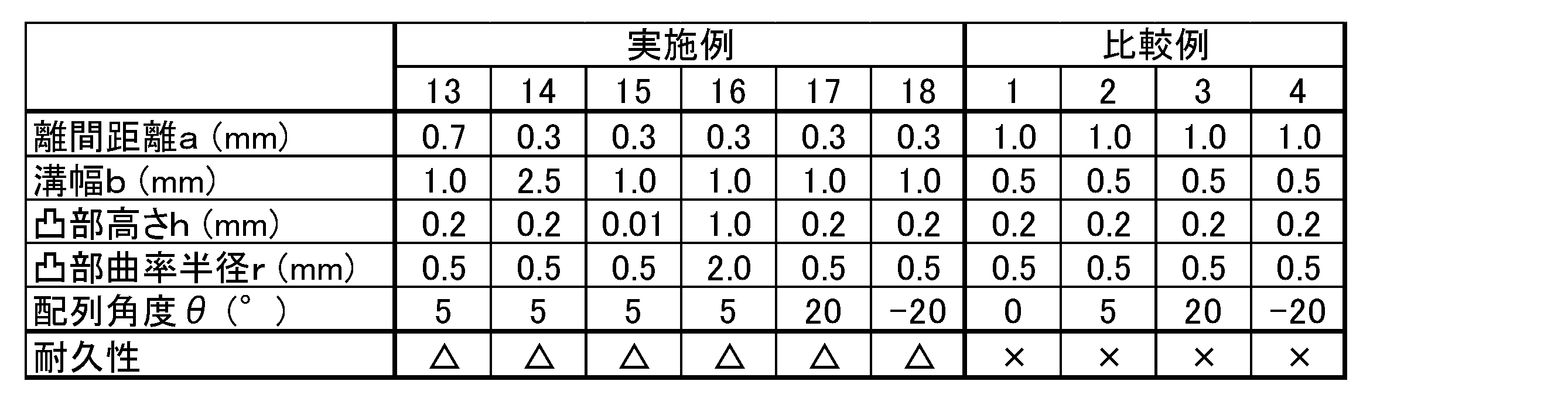
比較例によれば、溝の幅bが凸部の列内の凸部離間距離aよりも小さいものとなっており、紙粉による紙詰まりの発生回数が10回以上と多く、耐久性を満足していない。これに対し、実施例によれば、溝の幅bが凸部の列内の凸部離間距離aよりも大きいものとなっており、紙粉による紙詰まりの発生回数が9回以下と少なく、耐久性を満足している。
そして、実施例において、角度θが±10°以下であると、紙詰まりの発生回数がより抑えられることがわかる。また、角度θが0°よりも5°のほうが紙詰まりの発生回数がより抑えられることがわかる。また、凸部離間距離aが0.6mm以下、溝の幅bが2.0mm以下、1.5mm以下、凸部の高さhが0.05~0.5mmであると、紙詰まりの発生回数がより抑えられることがわかる。
(実施例19)
半球状の凸部に代えて、図7に示す球台状の凸部とした以外は実施例2と同様にして、紙送りロールを得た。球台状の凸部の上底は研磨面で構成されている。球台状の凸部は、弾性体層の周面に沿ってらせん状に配列している。そして、凸部の列とこれに平行な凸部の列により弾性体層の周面に沿って連続した凹部の溝が形成されている。各寸法については、以下の通りである。
凸部離間距離a:0.3mm、溝の幅b:1.0mm、凸部の配列角度θ:5°
半球状の凸部に代えて、図7に示す球台状の凸部とした以外は実施例2と同様にして、紙送りロールを得た。球台状の凸部の上底は研磨面で構成されている。球台状の凸部は、弾性体層の周面に沿ってらせん状に配列している。そして、凸部の列とこれに平行な凸部の列により弾性体層の周面に沿って連続した凹部の溝が形成されている。各寸法については、以下の通りである。
凸部離間距離a:0.3mm、溝の幅b:1.0mm、凸部の配列角度θ:5°
(実施例20)
半球状の凸部に代えて、図6に示す球台状の凸部とした以外は実施例2と同様にして、紙送りロールを得た。球台状の凸部の上底は平面で構成されている。球台状の凸部は、弾性体層の周面に沿ってらせん状に配列している。そして、凸部の列とこれに平行な凸部の列により弾性体層の周面に沿って連続した凹部の溝が形成されている。各寸法については、以下の通りである。
凸部離間距離a:0.3mm、溝の幅b:1.0mm、凸部の配列角度θ:5°
半球状の凸部に代えて、図6に示す球台状の凸部とした以外は実施例2と同様にして、紙送りロールを得た。球台状の凸部の上底は平面で構成されている。球台状の凸部は、弾性体層の周面に沿ってらせん状に配列している。そして、凸部の列とこれに平行な凸部の列により弾性体層の周面に沿って連続した凹部の溝が形成されている。各寸法については、以下の通りである。
凸部離間距離a:0.3mm、溝の幅b:1.0mm、凸部の配列角度θ:5°
実施例19~20について、作製した紙送りロールを用い、紙粉の発生量の測定と耐久性の評価をした。その結果を凸部の構成とともに表3に示す。
(紙粉発生量)
FRR方式の給紙システムを持った市販の複写機に紙送りロールを組み込み、市販のPPC用紙を用いて1万枚通紙を行った後、所定面積のテープをロール表面に貼り付けてロール表面の紙粉をテープに転写し、転写前後のテープ重量差を測定した。各紙送りロールの紙粉発生量を、実施例1の紙粉発生量を1としたときの相対比率で表した。その比率が1.0未満の場合を「◎」、その比率が1.0以上1.2未満の場合を「○」、その比率が1.2以上2.0未満の場合を「△」、その比率が2.0以上の場合を「×」とした。
FRR方式の給紙システムを持った市販の複写機に紙送りロールを組み込み、市販のPPC用紙を用いて1万枚通紙を行った後、所定面積のテープをロール表面に貼り付けてロール表面の紙粉をテープに転写し、転写前後のテープ重量差を測定した。各紙送りロールの紙粉発生量を、実施例1の紙粉発生量を1としたときの相対比率で表した。その比率が1.0未満の場合を「◎」、その比率が1.0以上1.2未満の場合を「○」、その比率が1.2以上2.0未満の場合を「△」、その比率が2.0以上の場合を「×」とした。
(耐久性の評価)
上記の通りである。
上記の通りである。
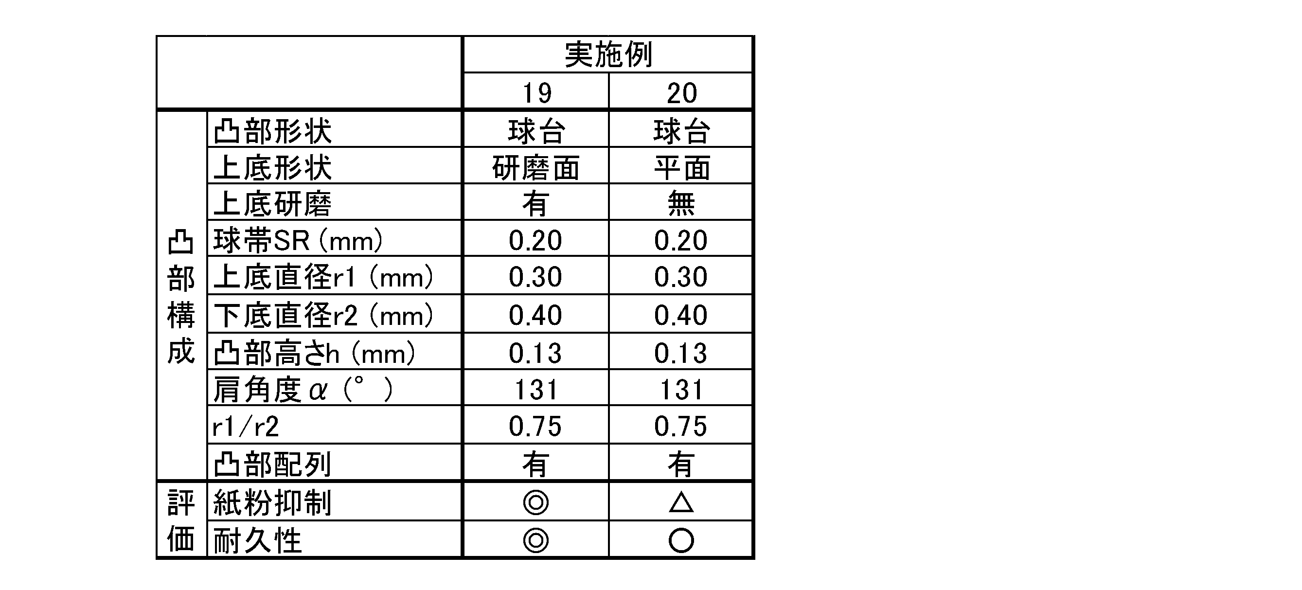
実施例19~20によれば、弾性体層の周面に形成された凸部が球台状であることで、紙粉の発生が抑えられ、耐久性が向上することがわかる。また、実施例19から、球台状の凸部の上底に研磨面が設けられているもののほうが、紙粉の発生が抑えられることがわかる。
以上、本発明の実施形態・実施例について説明したが、本発明は上記実施形態・実施例に何ら限定されるものではなく、本発明の趣旨を逸脱しない範囲内で種々の改変が可能である。
Claims (18)
- 軸体と、前記軸体の外周に形成された弾性体層と、を備え、
前記弾性体層の周面には、凸部により凹凸が設けられており、
前記凸部は、前記弾性体層の周面に沿って軸方向と異なる方向に配列しており、軸方向と異なる方向の凸部の列とこれに平行な凸部の列の間が連続した凹部の溝になっており、
前記溝の幅が、前記凸部の列内の凸部離間距離よりも大きいことを特徴とする紙送りロール。 - 前記凸部が、半球状の凸部であることを特徴とする請求項1に記載の紙送りロール。
- 前記凸部は、前記弾性体層の周面に沿って周方向とは異なる方向に配列していることを特徴とする請求項1または2に記載の紙送りロール。
- 前記凸部は、前記弾性体層の周面に沿ってらせん状に配列していることを特徴とする請求項3に記載の紙送りロール。
- 前記凸部は、前記弾性体層の周面に沿って周方向に対し±10°以内の角度の方向に配列していることを特徴とする請求項3または4に記載の紙送りロール。
- 前記凸部は、前記弾性体層の周面に沿って周方向に配列していることを特徴とする請求項1または2に記載の紙送りロール。
- 前記凸部の列内の凸部離間距離が、0~0.6mmの範囲内であることを特徴とする請求項1から6のいずれか1項に記載の紙送りロール。
- 前記溝の幅が、0.01~2.0mmの範囲内であることを特徴とする請求項1から7のいずれか1項に記載の紙送りロール。
- 前記凸部の高さが、0.05~0.5mmの範囲内であることを特徴とする請求項1から8のいずれか1項に記載の紙送りロール。
- 前記凸部の曲率半径が、0.05~1.0mmの範囲内であることを特徴とする請求項2から9のいずれか1項に記載の紙送りロール。
- 前記溝のピッチが、0.1~2.0mmの範囲内であることを特徴とする請求項1から10のいずれか1項に記載の紙送りロール。
- 前記凸部が、球台状の凸部であることを特徴とする請求項1に記載の紙送りロール。
- 前記凸部の上底が、研磨面であることを特徴とする請求項12に記載の紙送りロール。
- 前記凸部の上底が、平面であることを特徴とする請求項12に記載の紙送りロール。
- 前記凸部の上底が、前記凸部の球帯よりも曲率半径の大きい曲面であることを特徴とする請求項12に記載の紙送りロール。
- 前記凸部における上底の直径r1と下底の直径r2との比(r1/r2)が、0.50~0.95の範囲内であることを特徴とする請求項12から15のいずれか1項に記載の紙送りロール。
- 前記凸部の上底との交点における前記凸部の球帯の接面と、前記凸部の上底と、のなす角が、100~150°の範囲内であることを特徴とする請求項12から16のいずれか1項に記載の紙送りロール。
- 前記凸部の高さが、0.02~0.40mmの範囲内であることを特徴とする請求項12から17のいずれか1項に記載の紙送りロール。
Priority Applications (2)
| Application Number | Priority Date | Filing Date | Title |
|---|---|---|---|
| CN201880052090.5A CN111032544B (zh) | 2017-08-31 | 2018-07-31 | 送纸辊 |
| US16/662,036 US20200055683A1 (en) | 2017-08-31 | 2019-10-24 | Paper feed roller |
Applications Claiming Priority (4)
| Application Number | Priority Date | Filing Date | Title |
|---|---|---|---|
| JP2017-166590 | 2017-08-31 | ||
| JP2017166590A JP6843021B2 (ja) | 2017-08-31 | 2017-08-31 | 紙送りロール |
| JP2017-190262 | 2017-09-29 | ||
| JP2017190262A JP6843026B2 (ja) | 2017-09-29 | 2017-09-29 | 紙送りロール |
Related Child Applications (1)
| Application Number | Title | Priority Date | Filing Date |
|---|---|---|---|
| US16/662,036 Continuation US20200055683A1 (en) | 2017-08-31 | 2019-10-24 | Paper feed roller |
Publications (1)
| Publication Number | Publication Date |
|---|---|
| WO2019044330A1 true WO2019044330A1 (ja) | 2019-03-07 |
Family
ID=65525430
Family Applications (1)
| Application Number | Title | Priority Date | Filing Date |
|---|---|---|---|
| PCT/JP2018/028573 Ceased WO2019044330A1 (ja) | 2017-08-31 | 2018-07-31 | 紙送りロール |
Country Status (3)
| Country | Link |
|---|---|
| US (1) | US20200055683A1 (ja) |
| CN (1) | CN111032544B (ja) |
| WO (1) | WO2019044330A1 (ja) |
Cited By (1)
| Publication number | Priority date | Publication date | Assignee | Title |
|---|---|---|---|---|
| CN110239234A (zh) * | 2019-05-27 | 2019-09-17 | 西昌市人民医院 | 一种儿童保健管理信息平台 |
Families Citing this family (3)
| Publication number | Priority date | Publication date | Assignee | Title |
|---|---|---|---|---|
| US12129148B2 (en) | 2020-05-15 | 2024-10-29 | The Procter & Gamble Company | Durable transfer roll core and method of making and using the same |
| JP7487141B2 (ja) * | 2021-05-26 | 2024-05-20 | 住友理工株式会社 | 紙送りロール |
| USD1064732S1 (en) * | 2023-01-05 | 2025-03-04 | General Mills, Inc. | Feed roller |
Citations (5)
| Publication number | Priority date | Publication date | Assignee | Title |
|---|---|---|---|---|
| JPH0680292A (ja) * | 1992-09-02 | 1994-03-22 | Kato Hatsujo Kaisha Ltd | 紙送りローラ |
| JP2005212179A (ja) * | 2004-01-28 | 2005-08-11 | Seiko Epson Corp | 紙搬送機構及び記録装置 |
| JP2006076772A (ja) * | 2004-09-13 | 2006-03-23 | Fuji Photo Film Co Ltd | 搬送ローラ及び搬送装置並びに搬送ローラの製造方法 |
| JP2009096577A (ja) * | 2007-10-16 | 2009-05-07 | Ricoh Elemex Corp | 送りローラ及び送りローラ装置 |
| JP2017065907A (ja) * | 2015-10-01 | 2017-04-06 | 住友ゴム工業株式会社 | 紙送りローラ、および該紙送りローラを備えた画像形成装置 |
Family Cites Families (3)
| Publication number | Priority date | Publication date | Assignee | Title |
|---|---|---|---|---|
| JP4799672B2 (ja) * | 2010-04-13 | 2011-10-26 | 東洋鋼鈑株式会社 | ターンバー |
| CN102714951B (zh) * | 2012-07-13 | 2014-06-11 | 吉林大学 | 农业机械触土部件耦合仿生表面 |
| CN205802588U (zh) * | 2016-07-04 | 2016-12-14 | 海南大学 | 一种香蕉茎秆纤维提取仿生胶辊 |
-
2018
- 2018-07-31 WO PCT/JP2018/028573 patent/WO2019044330A1/ja not_active Ceased
- 2018-07-31 CN CN201880052090.5A patent/CN111032544B/zh active Active
-
2019
- 2019-10-24 US US16/662,036 patent/US20200055683A1/en not_active Abandoned
Patent Citations (5)
| Publication number | Priority date | Publication date | Assignee | Title |
|---|---|---|---|---|
| JPH0680292A (ja) * | 1992-09-02 | 1994-03-22 | Kato Hatsujo Kaisha Ltd | 紙送りローラ |
| JP2005212179A (ja) * | 2004-01-28 | 2005-08-11 | Seiko Epson Corp | 紙搬送機構及び記録装置 |
| JP2006076772A (ja) * | 2004-09-13 | 2006-03-23 | Fuji Photo Film Co Ltd | 搬送ローラ及び搬送装置並びに搬送ローラの製造方法 |
| JP2009096577A (ja) * | 2007-10-16 | 2009-05-07 | Ricoh Elemex Corp | 送りローラ及び送りローラ装置 |
| JP2017065907A (ja) * | 2015-10-01 | 2017-04-06 | 住友ゴム工業株式会社 | 紙送りローラ、および該紙送りローラを備えた画像形成装置 |
Cited By (2)
| Publication number | Priority date | Publication date | Assignee | Title |
|---|---|---|---|---|
| CN110239234A (zh) * | 2019-05-27 | 2019-09-17 | 西昌市人民医院 | 一种儿童保健管理信息平台 |
| CN110239234B (zh) * | 2019-05-27 | 2020-03-31 | 西昌市人民医院 | 一种儿童保健管理信息平台 |
Also Published As
| Publication number | Publication date |
|---|---|
| US20200055683A1 (en) | 2020-02-20 |
| CN111032544B (zh) | 2021-12-21 |
| CN111032544A (zh) | 2020-04-17 |
Similar Documents
| Publication | Publication Date | Title |
|---|---|---|
| WO2019044330A1 (ja) | 紙送りロール | |
| US9740150B2 (en) | Fixing device having fixing nip formed by elastic roller and a back-up unit with cylindrical film and film guide including a plurality of ribs extending circumferentially along the inner periphery of the film | |
| WO2021085365A1 (ja) | 給紙装置、紙送りロールおよび分離ロール | |
| CN111867949B (zh) | 送纸辊 | |
| US12103808B2 (en) | Paper feeding roll | |
| US9037028B2 (en) | Cleaning apparatus, process cartridge, and image forming apparatus | |
| JP6843026B2 (ja) | 紙送りロール | |
| US10423118B1 (en) | Cleaning member and image forming apparatus | |
| JP6843021B2 (ja) | 紙送りロール | |
| WO2020066242A1 (ja) | 紙送りロール | |
| EP1316853B1 (en) | Bias transfer roll | |
| JP2009003029A (ja) | 転造装置、現像ローラの製造方法、現像ローラ、現像装置、および画像形成装置 | |
| JP2008292594A (ja) | 現像ローラ、現像装置、および画像形成装置 | |
| JP7487141B2 (ja) | 紙送りロール | |
| US7067027B2 (en) | Method of making an electro-mechanical roll | |
| WO2022114054A1 (ja) | 紙送りロール | |
| JP2004133129A (ja) | 加熱定着ローラ、その製造方法及びそれを有する定着装置、並びに、その製造に用いられる圧接ローラ | |
| US20230264907A1 (en) | Paper feeding roller and paper feeding device | |
| JP2023094640A (ja) | 給紙装置、紙送りロールおよび分離ロール | |
| JPH10299762A (ja) | 弾性体ローラ |
Legal Events
| Date | Code | Title | Description |
|---|---|---|---|
| 121 | Ep: the epo has been informed by wipo that ep was designated in this application |
Ref document number: 18850436 Country of ref document: EP Kind code of ref document: A1 |
|
| DPE2 | Request for preliminary examination filed before expiration of 19th month from priority date (pct application filed from 20040101) | ||
| NENP | Non-entry into the national phase |
Ref country code: DE |
|
| 122 | Ep: pct application non-entry in european phase |
Ref document number: 18850436 Country of ref document: EP Kind code of ref document: A1 |